

Cambium Networks 54500, 58500 User Manual

PTP 500 Series
User Guide
MOTOROLA POINT-TO-POINT WIRELESS SOLUTIONS


MOTOROLA, Inc.
Point-to-Point Wireless Bridges – PTP 500 Series
Software Release PTP 500-03-xx
System User Guide
August 15th, 2008
Ref: PHN-1115-003v000
Copyright Information
This document is the confidential property of Motorola, Inc. and without its prior written consent may
not be copied or released to third parties.
MOTOROLA, the stylized M Logo and all other trademarks indicated as such herein are trademarks
of Motorola, Inc.
product or service names are the property of their respective owners.
© 2006-2008 Motorola, Inc. All rights reserved.
http://www.motorola.com/ptp
®
Reg. U.S. Pat & Tm. Office. PTP 500 is a trademark of Motorola, Inc. All other
Compliance
General
Changes or modifications not expressly approved by Motorola could void the user’s authority to
operate the system.
NOTE: This system has achieved Type Approval in various countries around the world. This means
that the system has been tested against various local technical regulations and found to comply. The
frequency bands in which the system operates may be ‘unlicensed’ and, in these bands, the system
can be used provided it does not cause interference. Further, it is not guaranteed protection against
interference from other products and installations.
1

The system has been tested for compliance to both US (FCC) and European (ETSI) specifications. It
has been shown to comply with the limits for emitted spurious radiation for a Class B digital device
1
pursuant to Part 15 of the FCC Rules in the USA and appropriate European ENs. These limits have
,
been designed to provide reasonable
protection against harmful interference. However the equipment
can radiate radio frequency energy and, if not installed and used in accordance with the instructions,
may cause harmful interference to other radio communications. There is no guarantee that
interference will not occur in a particular installation.
If this equipment does cause harmful interference to radio or television reception, which can be
determined by turning the equipment off and on, the user is encouraged to try to correct the
interference by one or more of the following measures:
• Reorient or relocate the Outdoor Unit (ODU).
• Increase the separation between the affected equipment and ODU.
• Connect the ODU/PIDU into a power outlet on a circuit different from that to which the
receiver is connected.
• Consult your installer or supplier for help.
Deployment and Operation
The Radio Regulations of various countries’ limits constrain the operation of radio products generally.
In particular the local regulator may limit the amount of conducted or radiated transmitter power and
may require registration of the radio link.
The power transmitted by the PTP 500 Series Bridge is controlled by the use of Region-specific
License Keys.
The following examples show how the regulatory limits apply in some specific countries at the current
time. Operators should note that regulations are subject to change.
Contact your supplier/installer to ensure that your product is set for the correct License Key for your
Country/Region and to ensure that you have fulfilled all the local regulatory requirements, especially if
you are intending to use a link with external antennas. Notes below the tables indicate countries
where registration of the link is currently mandatory.
1
Class B Digital Device, A digital device that is marketed for use in a residential environment, notwithstanding use in
commercial, business and industrial environments.
2

Regulations applicable to PTP 54500 variant
FCC
ETSI
Canada
Examples of Regulatory Limits at 5.4GHz
Under FCC Regulations, operation of this product is only allowed with a
License Key for Region 12. This implements Radar Detection in
accordance with FCC Regulations and limits the EIRP to the regulatory
limits below:
EIRP ≤ Max of [(17 +10 x Log(Channel BW)) and 30]dBm
Under ETSI Regulations, operation of this product is only allowed with
a License Key for Region 26. This implements Radar Detection in
accordance with ETSI Regulations, including barring of the band from
5600MHz to 5650MHz and limits the EIRP to the regulatory limits
below:
EIRP ≤ Max of [(17 +10 x Log(Channel BW)) and 30]dBm
Under Industry Canada Regulations, operation of this product is only
allowed with a License Key for Region 13. This implements Radar
Detection in accordance with Canadian Regulations, including barring
of the band from 5600MHz to 5650MHz and limits the EIRP to the
regulatory limits below:
EIRP ≤ Max of [(17 +10 x Log(Channel BW)) and 30]dBm
General Notice Applicable to Europe
This equipment complies with the essential requirements for the
EU R&E Directive 1999/5/EC.
NOTE: In regions other than EU/USA, specific local regulations may apply. It is the responsibility of
the installer/user to check that the equipment as deployed meets local regulatory requirements.
3

Regulations applicable to PTP 58500 variant
USA/ Canada/
Taiwan
UK
Eire
Norway Under Norway Regulations, operation of this product is only allowed with a
Germany Operation of this product is only allowed with a License Key for Region 22 This
Denmark Operation of this product is only allowed with a License Key for Region 27 .
Examples of Regulatory Limits
Equipment can be operated in any mode, best results will be obtained using
Region 1 settings
Under UK Regulations, operation of this product is allowed with a License Key
for Region 4 . This implements Radar Detection with barring of the band from
5795MHz to 5815MHz and above 5850MHz. It limits the EIRP to the
Regulatory Limits below:
EIRP ≤ Max of [(23 +10 x Log(Channel BW)) and 36]dBm
Under Eire Regulations, operation of this product is only allowed with a License
Key for Region 6. This implements Radar Detection and limits the EIRP to the
Regulatory Limits below:
EIRP ≤ Max of [(20 +10 x Log(Channel BW)) and 33]dBm
License Key for Region 7. This limits the EIRP to the Regulatory Limits below:
EIRP ≤ Max of [(40 +10 x Log(Channel BW)) and 53]dBm
limits the band of operation to 5755MHz to 5875MHz and limits the EIRP to the
Regulatory Limits below:
EIRP ≤ Max of [(23 +10 x Log(Channel BW)) and 36]dBm
This implements Radar Detection with barring of the band from 5795MHz to
5815MHz. It limits the EIRP to the Regulatory Limits below:
EIRP ≤ Max of [(23 +10 x Log(Channel BW)) and 36]dBm
General Notice Applicable to Europe
This equipment complies with the essential requirements for the EU R&E Directive
1999/5/EC.
The use of 5.8GHz for Point to Point radio links is not harmonized across the EU.
However, the regulatory situation in Europe is changing and the radio spectrum may
become available in other countries in the near future. Please contact Motorola for the
latest situation.
4

NOTES:
UK Registration of Links – OfCom, The application form may be found at:
http://www.ofcom.org.uk/radiocomms/isu
Eire Registration of Links – Commission for Communication Regulation, The application form
may be found at:
http://www.comreg.ie/licensing_and_services
Disclaimer
The parameters quoted in this document must be specifically confirmed in writing
before they become applicable to any particular order or contract. The company
reserves the right to make alterations or amendments to the detail specification at its
discretion. The publication of information in this document does not imply freedom
from patent or other rights of Motorola, Inc. or others.
5

Contents
1 About This User Guide.......................................................................................................19
1.1 Interpreting Typeface and Other Conventions...................................................................... 19
1.2 Getting Additional Help ......................................................................................................... 21
1.3 Sending Feedback ................................................................................................................ 21
2 Avoiding Hazards................................................................................................................22
2.1 Preventing Overexposure to RF Energy ............................................................................... 22
2.1.1 Calculations for Separation Distances and Power Compliance Margins.............................. 22
3 Getting Started .................................................................................................................... 25
3.1 For Your Safety ..................................................................................................................... 25
3.2 Welcome ...............................................................................................................................26
3.2.1 Who Should Use This Guide................................................................................................. 26
3.2.2 Contact Information ............................................................................................................... 26
3.2.3 Repair and Service................................................................................................................ 26
3.3 Product Description............................................................................................................... 27
3.3.1 The Outdoor Unit (ODU) ....................................................................................................... 28
3.3.2 PIDU Plus – PTP 300/500/600 Series Bridge....................................................................... 29
3.3.3 Redundancy and Alternative Powering Configurations......................................................... 31
3.3.4 Remote LEDs and Recovery Switch..................................................................................... 33
3.3.5 Cables and connectors ......................................................................................................... 33
3.3.6 PTP and Lightning Protection ...............................................................................................34
3.3.7 Mounting Brackets................................................................................................................. 34
3.3.8 Configuration and Management............................................................................................ 35
3.4 Warranty................................................................................................................................35
4 Product Architecture .......................................................................................................... 36
5 General Considerations .....................................................................................................39
5.1 Spectrum Planning................................................................................................................ 39
5.2 Licenses and Region Codes ................................................................................................. 40
5.3 Operational Restrictions........................................................................................................ 42
5.3.1 Radar Avoidance................................................................................................................... 42
5.3.2 5.8GHz Restrictions ..............................................................................................................43
5.4 Channel Bandwidth Operation .............................................................................................. 44
5.5 PTP 54500 Specific Frequency Planning Considerations .................................................... 45
5.5.1 PTP 54500 Raster Considerations:....................................................................................... 45
5.5.2 Transmit Power Reduction at the Band Edges ..................................................................... 45
6

PTP 58500 Specific Frequency Planning Considerations .................................................... 46
5.6
5.6.1 PTP 58500 Raster Considerations........................................................................................ 46
PTP ....................................................................................................................................... 47
5.6.2 58500 Transmit Power Reduction at the Band Edges.......................................................... 47
5.7 Distance ................................................................................................................................48
5.8 Networking Information .........................................................................................................48
5.9 Lightning Protection and Regulations ................................................................................... 48
5.10 Electrical Requirements ........................................................................................................ 48
6 Site Planning........................................................................................................................49
6.1 Site Selection Criteria............................................................................................................ 49
6.1.1 ODU Site Selection ...............................................................................................................49
6.1.2 PTP 500 Series Bridge PIDU Plus Site Selection................................................................. 49
6.1.3 Path Loss Considerations ..................................................................................................... 50
6.1.4 Definitions.............................................................................................................................. 50
6.1.5 PTP 54500 Product Variant - Link Loss, Output Power and System Threshold versus
Modulation Mode ..................................................................................................................................52
6.1.6 PTP 58500 Product Variant - Link Loss, Output Power and System Threshold versus
Modulation Mode ..................................................................................................................................54
7 Installation ........................................................................................................................... 56
7.1 Preparation............................................................................................................................ 56
7.2 Installation Procedure ........................................................................................................... 56
7.3 Tools Required...................................................................................................................... 57
7.4 Installation Support................................................................................................................ 57
7.5 Legal Disclaimer.................................................................................................................... 57
7.6 Mounting the ODUs............................................................................................................... 58
7.7 Connecting Up....................................................................................................................... 60
7.7.1 Preparing the PIDU Plus To ODU Cable .............................................................................. 60
7.7.2 Making the Connections at the ODU..................................................................................... 62
7.7.3 Making the PTP 300/500/600 Series Bridge PIDU Plus Connection At The ODU............... 63
7.7.4 Routing the Cable.................................................................................................................. 64
7.7.5 Fitting a Lightning Protection Unit ......................................................................................... 64
7.7.6 Grounding the Installation..................................................................................................... 65
7.7.7 Making the ODU Connection at the PTP 300/500/600 Series Bridge PIDU Plus................. 65
7.7.8 Making the Network Connection at The PIDU Plus – PTP 500 Series Bridge ..................... 66
7.7.9 Mounting the PTP 300/500/600 Series Bridge PIDU Plus.................................................... 66
7.7.10 Powering Up.......................................................................................................................... 68
7.7.11 Aligning the PTP 500 Series Bridge ODUs........................................................................... 69
7

Additional Installation Notes.................................................................................................. 72
7.7.12
8 Web Page Reference...........................................................................................................73
8.1 Home Page – PTP 500 Series Bridge................................................................................... 75
8.1.1 Home Page Alarm Display .................................................................................................... 76
8.2 Systems Status Page............................................................................................................ 81
8.3 System Administration Pages ............................................................................................... 86
8.3.1 System Configuration............................................................................................................ 87
8.3.2 Statistics Page....................................................................................................................... 99
8.3.3 Detailed Counters Page ......................................................................................................102
8.3.4 Install Pages........................................................................................................................ 104
8.3.5 Graphical Install................................................................................................................... 115
8.3.6 Software Upgrade ...............................................................................................................116
8.3.7 Spectrum Management....................................................................................................... 119
8.3.8 Spectrum Management (Fixed Frequency) ........................................................................127
8.3.9 Spectrum Management Control - With Operational Restrictions........................................ 128
8.3.10 Remote Management Page ................................................................................................ 132
8.3.11 Diagnostics.......................................................................................................................... 137
8.3.12 Change System Administration Password.......................................................................... 140
8.3.13 License Key......................................................................................................................... 140
8.3.14 Properties ............................................................................................................................ 141
8.3.15 Reboot................................................................................................................................. 142
9 Recovery Mode.................................................................................................................. 143
9.1 Upgrade Software Image .................................................................................................... 144
9.2 Reset IP & Ethernet Configuration...................................................................................... 146
9.3 Erase Configuration............................................................................................................. 147
9.4 Erase Security Parameters ................................................................................................. 148
9.5 Reboot................................................................................................................................. 149
10 Fault Finding......................................................................................................................150
10.1 Hardware............................................................................................................................. 150
10.1.1 Power .................................................................................................................................. 150
10.1.2 Ethernet............................................................................................................................... 151
10.1.3 Checking your wiring........................................................................................................... 152
10.2 Radio ................................................................................................................................... 153
10.2.1 No Activity ........................................................................................................................... 153
10.2.2 Some Activity....................................................................................................................... 154
11 Lightning Protection.........................................................................................................155
8

Overview ............................................................................................................................. 155
11.1
11.1.1 Lightning Protection Zones .................................................................................................155
11.2 Detailed Installation............................................................................................................. 157
11.3 Testing Your Installation...................................................................................................... 160
11.3.1 Pre-Power Testing............................................................................................................... 161
11.3.2 Post-Power Testing ............................................................................................................. 162
11.4 Locating the Fault................................................................................................................ 163
12 Wind Loading.....................................................................................................................164
12.1 General................................................................................................................................ 164
12.2 Calculation of Lateral Force ................................................................................................ 164
12.3 Capabilities of the PTP 500 Series Bridges ........................................................................ 165
12.4 Wind Speed Statistics ......................................................................................................... 165
13 PTP 500 Series Bridge – Connectorized Model .............................................................166
13.1 Scope .................................................................................................................................. 166
13.2 Product Description............................................................................................................. 166
13.2.1 Hardware............................................................................................................................. 166
13.2.2 Antenna Choices – 5.8 GHz................................................................................................ 167
13.2.3 Suggested Antenna Choices – 5.4 GHz ............................................................................. 167
13.3 Software/Features............................................................................................................... 168
13.3.1 Status Page......................................................................................................................... 168
13.3.2 Configuration Pages............................................................................................................ 169
13.3.3 Installation Pages................................................................................................................ 170
13.4 Deployment Considerations ................................................................................................ 172
13.5 Link Budget .........................................................................................................................173
13.6 Regulatory Issues................................................................................................................ 173
13.6.1 Antenna Choice (FCC and Industry Canada Regions Only) ..............................................174
13.6.2 Cable Losses (FCC Regions Only)..................................................................................... 174
13.6.3 Antennas for USA / Canada – 5.8 GHz............................................................................... 175
13.6.4 Suggested Antennas - 5.4 GHz ..........................................................................................178
13.7 Installation ........................................................................................................................... 180
13.7.1 Antenna Choice................................................................................................................... 180
13.7.2 Cables and Connectors....................................................................................................... 180
13.7.3 Tools.................................................................................................................................... 180
13.7.4 Miscellaneous supplies .......................................................................................................181
13.7.5 Mounting the Connectorized 500 Series Bridge ................................................................. 181
13.7.6 Mounting the antennas........................................................................................................ 181
9

Alignment Process ..............................................................................................................181
13.7.7
13.7.8 Aligning Dual Polar Antennas .............................................................................................182
13.7.9 Aligning Separate Antennas................................................................................................ 182
13.7.10 Completing the Installation.................................................................................................. 183
13.7.11 Antenna Cable Fixing.......................................................................................................... 183
13.7.12 Antenna Connection Weatherproofing................................................................................ 184
13.8 Additional Lightning Protection............................................................................................ 185
13.8.1 ODU Mounted Outdoors ..................................................................................................... 185
13.8.2 ODU Mounted Indoors ........................................................................................................ 186
14 Data Rate Calculations.....................................................................................................187
15 AES Encryption Upgrade ................................................................................................. 194
15.1 Configuring Link Encryption ................................................................................................ 194
15.1.1 License Keys ....................................................................................................................... 194
15.1.2 Encryption Mode and Key ................................................................................................... 196
15.2 Wireless Link Encryption FAQ ............................................................................................197
15.2.1 Encryption data entry fields are not available ..................................................................... 197
15.2.2 Link fails to bridge packets after enabling link encryption................................................... 197
15.2.3 Loss of AES following downgrade....................................................................................... 197
16 Legal and Regulatory Notices..........................................................................................198
16.1 Important Note on Modifications .........................................................................................198
16.2 National and Regional Regulatory Notices – PTP 58500 variant .......................................198
16.2.1 U.S. Federal Communication Commission (FCC) and Industry Canada (IC) Notification..198
16.2.2 European Union Notification ............................................................................................... 199
16.2.3 UK Notification..................................................................................................................... 200
16.3 National and Regional Regulatory Notices – PTP 54500 Variant....................................... 201
16.3.1 FCC and Industry Canada (IC) Notification ........................................................................ 201
16.3.2 European Union Notification ............................................................................................... 202
16.4 Exposure ............................................................................................................................. 203
16.5 Legal Notices....................................................................................................................... 204
16.5.1 Motorola Inc. End User License Agreement ....................................................................... 204
16.5.2 Hardware Warranty in U.S. ................................................................................................. 213
16.5.3 Limit of Liability.................................................................................................................... 213
17 Specifications....................................................................................................................214
17.1 System Specifications .........................................................................................................214
17.1.1 Wireless PTP 54500 Variant ............................................................................................... 214
17.1.2 Wireless PTP 58500 Variant ............................................................................................... 215
10

Management .......................................................................................................................216
17.1.3
17.1.4 Ethernet Bridging................................................................................................................. 216
17.1.5 Physical ...............................................................................................................................217
17.1.6 Powering ............................................................................................................................. 217
17.2 Safety Compliance .............................................................................................................. 217
17.3 EMC Emissions Compliance............................................................................................... 218
17.3.1 PTP 54500 Variant.............................................................................................................. 218
17.3.2 PTP 58500 Variant.............................................................................................................. 218
17.4 EMC Immunity Compliance................................................................................................. 219
17.5 Radio Certifications .............................................................................................................220
17.5.1 PTP 54500 Variant.............................................................................................................. 220
17.5.2 PTP 58500 Variant.............................................................................................................. 220
17.6 Environmental Specifications .............................................................................................. 220
17.7 System Connections ........................................................................................................... 221
17.7.1 PIDU Plus to ODU and ODU to Network Equipment Connections..................................... 221
18 FAQs...................................................................................................................................222
19 Glossary............................................................................................................................. 224
20 Index...................................................................................................................................225
11

1 About This User Guide
List of Figures
Figure 1 - Typical PTP 500 Series Bridge Deployment........................................................................ 27
Figure 2 – PTP 500 Series Bridge Outdoor Unit (ODU) with PTP-LPU ............................................... 28
Figure 3 - Power Indoor Unit (PIDU Plus) – PTP 300/500/600 Series................................................. 29
Figure 4 – PIDU Plus Recovery Switch Location................................................................................. 29
Figure 5 –PTP 300/500/600 Series Bridge PIDU Plus Power Input..................................................... 31
Figure 6 - External DC Supply Only .....................................................................................................31
Figure 7 - External DC Supply and AC Supply..................................................................................... 32
Figure 8 - External DC Supply and Redundant AC Supply.................................................................. 32
Figure 9 - Remote LED and Recovery Switch Wiring ..........................................................................33
Figure 10 – PTP 500 Series Bridge Layer Diagram............................................................................. 37
Figure 11 - 5.8 GHz UK RTTT Channel Avoidance – 15 MHz Channel Bandwidth Only.................... 44
Figure 12 - 5.4 GHz Available Spectrum Settings - 15 MHz Channel Bandwidth................................ 45
Figure 13 - 5.8 GHz Available Spectrum Settings – 15 MHz Channel Bandwidth............................... 46
Figure 14 - Mounting to pole diameters 25mm (1”) to 50mm (2”) ........................................................58
Figure 15 - Integral Safety Loop ........................................................................................................... 59
Figure 16 - Correct Cable Preparation for the Recommended Cable.................................................. 60
Figure 17 - Completed ODU Connector ............................................................................................... 61
Figure 18 - Warning Not To Over tighten Cable Gland ........................................................................61
Figure 19 – PTP 500 Series Bridge PIDU Plus Connexion.................................................................. 62
Figure 20 - Connecting the PIDU+ to the ODU ....................................................................................63
Figure 21 - Disconnecting the ODU...................................................................................................... 64
Figure 22 - Making the Network Connection at the PIDU Plus ............................................................ 66
Figure 23 – PTP 500 Series PIDU Plus Drip Loop Configuration ........................................................ 67
Figure 24 - Using DVM For Alignment.................................................................................................. 71
Figure 25 - Menu Navigation Bar.......................................................................................................... 74
Figure 26 - System Summary Page .....................................................................................................75
12

1 About This User Guide
Figure 27 - Alarm Warning Triangle .....................................................................................................76
Figure 28 - Status Page........................................................................................................................ 81
Figure 29 - System Administration Login Page.................................................................................... 86
Figure 30 - System Configuration Page ............................................................................................... 87
Figure 31 - LAN Configuration Page .................................................................................................... 89
Figure 32 - Configuration Reboot Page................................................................................................ 90
Figure 33 - Configuration Reboot Page - Ethernet Auto Negotiation Disabled.................................... 90
Figure 34 - VLAN Configuration Fields................................................................................................. 91
Figure 35 - QoS Configuration Page ....................................................................................................92
Figure 36 - Save and Restore Configuration Page .............................................................................. 95
Figure 37 - Save Configuration File Screen ......................................................................................... 96
Figure 38 – PTP 500 Example Configuration File................................................................................ 96
Figure 39 - Restore Configuration File Pop Up Screen........................................................................ 97
Figure 40 - Reset Configuration and Reboot Confirmation Pop-up .....................................................98
Figure 41 - System Statistics................................................................................................................ 99
Figure 42 - Detailed Counters Page................................................................................................... 102
Figure 43 - License Key Data Entry.................................................................................................... 105
Figure 44 - Installation Wizard Internet Protocol Configuration.......................................................... 106
Figure 45 - VLAN Warning .................................................................................................................107
Figure 46 –PTP 58500 and PTP 54500 Variants - Installation Wizard Wireless Configuration........ 108
Figure 47 –PTP 58500 and PTP 54500 Variants - Fixed Frequency Operation................................ 111
Figure 48 –PTP 58500 and PTP 54500 Variants - Installation Wizard Confirm Configuration.......... 112
Figure 49 - Reboot Confirmation Pop Up ...........................................................................................112
Figure 50 –PTP 58500 and PTP 54500 Variant - Disarm Installation................................................ 113
Figure 51 - Optional Post Disarm Configuration 2.............................................................................. 114
Figure 52 – Graphical Installation Screen .......................................................................................... 115
Figure 53 - Software Upgrade ............................................................................................................ 116
13

1 About This User Guide
Figure 54 - Software Upgrade Image Check...................................................................................... 117
Figure 55 - Software Download Progress Indicator............................................................................ 118
Figure 56 - Software Upgrade Complete............................................................................................ 118
Figure 57 - Reboot Confirmation Pop Up ...........................................................................................119
Figure 58 - Spectrum Management as seen from the Master............................................................ 122
Figure 59 - Spectrum Management as seen from the Slave.............................................................. 122
Figure 60 - Active Channel History Screen ........................................................................................ 125
Figure 61 - Spectrum Management Time Series Plot ........................................................................126
Figure 62 - Spectrum Management Fixed Frequency Screen ...........................................................127
Figure 63 - Spectrum Management Help Page (Fixed Frequency) ................................................... 128
Figure 64 - Spectrum Management Master Screen With Operational Restrictions ...........................129
Figure 65 - Spectrum Management Slave Screen With Operational Restrictions .............................130
Figure 66 - Remote Management....................................................................................................... 132
Figure 67 – Warning when disabling HTTP Interface......................................................................... 133
Figure 68 - Remote Management - Diagnostic Alarms ...................................................................... 134
Figure 69 - Diagnostic Plotter ............................................................................................................. 138
Figure 70 - CSV Download................................................................................................................. 139
Figure 71 - Password Change............................................................................................................ 140
Figure 72 - Software License Key Data Entry .................................................................................... 140
Figure 73: License Key reboot Screen ...............................................................................................141
Figure 74 - Reboot Confirmation Pop Up ...........................................................................................141
Figure 75 – Properties ........................................................................................................................141
Figure 76 - System Reboot................................................................................................................. 142
Figure 77 - Reboot Confirmation Pop Up ...........................................................................................142
Figure 78 - Recovery Mode Warning Page ........................................................................................ 143
Figure 79 - Recovery Options Page ...................................................................................................143
Figure 80 - Software Download Progress Indicator Page .................................................................. 145
14

1 About This User Guide
Figure 81 - Software Download Complete Page................................................................................ 145
Figure 82 - Reboot Confirmation Pop Up ...........................................................................................145
Figure 83 - Confirm Reset to Factory Default Pop Up........................................................................ 146
Figure 84 - IP and Ethernet Erased Successfully page...................................................................... 146
Figure 85 - Reboot Confirmation Pop Up ...........................................................................................147
Figure 86 - Confirm Erase Configuration Pop Up............................................................................... 147
Figure 87 - Erase Configuration Successful Page .............................................................................147
Figure 88 – Erase Configuration - Reboot Confirmation Pop Up....................................................... 148
Figure 89 - Confirm Zeroise Security Parameters Pop Up................................................................. 148
Figure 90 - Zeroise Security Parameters Successful Page................................................................149
Figure 91 – Recovery - Reboot Confirmation Pop Up........................................................................ 149
Figure 92 - ODU mounted in Zones A & B ......................................................................................... 156
Figure 93 - Showing how the use of a Finial enables the ODU to be mounted inside Zone B .......... 157
Figure 94 - Diagrammatically Showing Typical Mast and Wall Installations ...................................... 158
Figure 95 - PTP LPU Installation Example for PTP 500 Series (Not to Scale) ..................................158
Figure 96 - PTP 500 Series LPU Kit................................................................................................... 159
Figure 97 - Simplified Circuit Diagram................................................................................................ 160
Figure 98 - PTP LPU test Points ........................................................................................................163
Figure 99 – Connectorized 500 Series Bridge Outdoor Unit.............................................................. 166
Figure 100 - Connectorized 500 Series bridge Status Page.............................................................. 168
Figure 101 - Connectorized 500 Series bridge ‘System Configuration’ Page.................................... 169
Figure 102 - Connectorized PTP 500 Series Bridge ‘Installation Wizard’ Page ...............................170
Figure 103 - Connectorized 500 Series bridge ‘Confirm Installation’ Page........................................171
Figure 104 - Connectorized 500 Series bridge ‘Disarm Installation’ Page......................................... 172
Figure 105 - Forming a Drip Loop ......................................................................................................184
Figure 106 - Weatherproofing the Antenna Connections................................................................... 184
Figure 107- Additional Grounding When Using Connectorized Units ................................................ 185
15

1 About This User Guide
Figure 108 - Lightning Arrestor Mounting........................................................................................... 186
Figure 109 - Polyphaser Assembly..................................................................................................... 186
Figure 110 - BPSK 0.50 Single Payload............................................................................................. 187
Figure 111 - QPSK 0.50 Single Payload ............................................................................................188
Figure 112 - QPSK 0.75 Single Payload ............................................................................................188
Figure 113 - 16 QAM 0.50 Single Payload......................................................................................... 189
Figure 114 - 16 QAM 0.75 Single Payload......................................................................................... 189
Figure 115 - 64 QAM 0.67 Single Payload......................................................................................... 190
Figure 116 - 64 QAM 0.83 Single Payload......................................................................................... 190
Figure 117 – QPSK 0.50 Dual Payload.............................................................................................. 191
Figure 118 - QPSK 0.75 Dual Payload............................................................................................... 191
Figure 119 - 16 QAM 0.50 Dual Payload ...........................................................................................192
Figure 120 - 16 QAM 0.75 Dual Payload ...........................................................................................192
Figure 121 - 64 QAM 0.67 Dual Payload ...........................................................................................193
Figure 122 - 64 QAM 0.83 Dual Payload ...........................................................................................193
Figure 123 – AES Software License Key Data Entry ......................................................................... 195
Figure 124 – AES Configuration Data Entry Page ............................................................................. 196
Figure 125 - Configuration Reboot Screen......................................................................................... 197
Figure 126 - Cable Connection Diagram (T568B Color Coding)........................................................221
16

1 About This User Guide
List of Tables
Table 1 - Font types............................................................................................................................ 19
Table 2 - Admonition types................................................................................................................... 20
Table 3 - Power Compliance Margins .................................................................................................. 23
Table 4 - Contact Information ............................................................................................................... 26
Table 5 - PTP 500 Series Bridge Frequency Variants ......................................................................... 39
Table 6 – PTP 58500 Licenses and Region Codes ............................................................................. 41
Table 7 – PTP 54500 Licenses and Region Codes ............................................................................. 42
Table 8 – PTP 58500 FCC Max Transmit Power at the Edge Channels (FCC) .................................. 47
Table 9 - PTP 54500 - IP Mode –System Threshold Figures – 15MHz BW ........................................ 52
Table 10 - PTP 54500 - TDM Mode – System Threshold Figures – 15 MHz BW................................ 53
Table 11 - PTP 58500 - IP Mode –System Threshold Figures – 15 MHz BW ..................................... 54
Table 12 - PTP 58500 - TDM Mode –System Threshold Figures – 15 MHz BW................................. 55
Table 13 - Audio indications from the ODU.......................................................................................... 69 U
Table 14 - Graphical Installation Behavior ...........................................................................................70
Table 15 – QoS Default Settings .......................................................................................................... 93
Table 16 – Classification rules upgrade example................................................................................. 93
Table 17 – IEEE802.1Q Classification rules ........................................................................................94
Table 18 – 500 Series Bridge Factory Configuration Values ............................................................. 104
Table 19 - Spectrum Management change state key......................................................................... 125
Table 20 - Spectrum Management Time Series Key .........................................................................126
Table 21 - Spectrum Management Change State Key With Operational Restrictions....................... 131
Table 22 - Power Indoor Unit LED check chart.................................................................................. 152
Table 23 - Resistance Table Referenced To The RJ45 at the PIDU+ ............................................... 161
Table 24 - Lateral Force – Imperial ....................................................................................................164
Table 25 - Lateral Force – Metric .......................................................................................................164
Table 26 - Cable Losses per Length .................................................................................................. 174
17

1 About This User Guide
Table 27 - Allowed Antennas for Deployment in USA/Canada – 5.8 GHz......................................... 177
Table 28 - Suggested Antennas – 5.4 GHz....................................................................................... 179
List of Equations
Equation 1 - Path Loss ......................................................................................................................... 50
Equation 2 - Link Loss ..........................................................................................................................84
18

1 About This User Guide
1 About This User Guide
This guide covers the installation, commissioning, operation and fault finding of the Motorola
PTP 500 Series of Point-to-Point Wireless Ethernet Bridges.
1.1 Interpreting Typeface and Other Conventions
This document employs distinctive fonts to indicate the type of information, as described in
Table 1.
Font Type of Information
variable width bold
constant width regular
constant width italic
constant width bold
constant width bold
italic
This document employs specific imperative terminology as follows:
• Type means press the following characters.
• Enter means type the following characters and then press Enter.
• Highlight means click anywhere in a row of data to highlight the entire row.
• Select means use the mouse to click on or branch to the menu item that follows.
Use this table and the Glossary to aid in interpreting the technical acronyms used throughout
Selectable option in a graphical user interface or
settable parameter in a web-based interface.
Literal system response in a command-line interface.
Variable system response in a command-line interface.
Literal user input in a command-line interface.
Variable user input in a command-line interface.
Table 1 - Font types
this User Guide.
19
1 About This User Guide
This document also employs a set of consistently used admonitions. Each type of admonition
has a general purpose that underlies the specific information in the box. These purposes are
indicated in Table 2.
Admonition
Label
General Message
Note Informative content that may:
• Defy common or cursory logic.
• Describe a peculiarity of the 500 Series solutions implementation.
• Add a conditional caveat.
• Provide a reference.
• Explain the reason for a preceding statement or provide background
for what immediately follows.
Recommendation Suggestion for an easier, quicker, or safer action or
practice.
Important Informative content that may:
• Identify an indication that you should watch for.
• Advise that your action can disturb something that you may not want
disturbed.
• Reiterate something that you presumably know but should always
keep in mind.
Caution! A notice that the risk of harm to equipment or service exists.
Warning! A notice that the risk of harm to person exists.
Table 2 - Admonition types
20

1 About This User Guide
1.2 Getting Additional Help
To get information or assistance as soon as possible for problems that you encounter, follow
this procedure:
1. Search this document, the user manuals that support the modules, and the software
release notes of supported releases:
a. In the Table of Contents for the topic.
b. In the Adobe Reader® search capability for keywords that apply.
2
2. Visit the Motorola website at www.motorola.com/ptp
3. Ask your Motorola products supplier to help.
4. Gather information from affected units such as:
a. the IP addresses and MAC addresses
b. the software releases
c. the configuration of software features
d. any available diagnostic downloads
5. Escalate the problem to Motorola Technical Support as follows. You may either:
a. Send e-mail to support.ptp@motorola.com
b. Call our 24x7 Technical Support Center on +1 (0) 877 515 0400 (Worldwide) or
+44 (0) 808 234 4640 (UK Customers).
For warranty assistance, contact your reseller or distributor for the process.
1.3 Sending Feedback
We welcome your feedback on the PTP 500 Series Bridge system documentation. This
includes feedback on the structure, content, accuracy, or completeness of our documents,
and any other comments you have. Send feedback to support.ptp@motorola.com
2
Adobe Reader is a registered trademark of Adobe Systems, Incorporated.
21
.

2 Avoiding Hazards
2 Avoiding Hazards
2.1 Preventing Overexposure to RF Energy
WARNING: To protect from overexposure to RF energy, install the radios for the 500 family
of PTP wireless solutions so as to provide and maintain the minimum separation distances
from all persons as shown in Table 3.
When the system is operational, avoid standing directly in front of the antenna. Strong RF
fields are present when the transmitter is on. The Outdoor Unit (ODU) must not be deployed
in a location where it is possible for people to stand or walk inadvertently in front of the
antenna.
At these and greater separation distances, the power density from the RF field is below
generally accepted limits for the general population.
NOTE: These are conservative distances that include compliance margins.
2.1.1 Calculations for Separation Distances and Power Compliance Margins
Limits and guidelines for RF exposure come from:
• US FCC limits for the general population. See the FCC web site at http://www.fcc.gov
• Health Canada limits for the general population. See the Health Canada web site at
• EN 50383:2002 Basic standard for the calculation and measurement of electromagnetic
and the policies, guidelines, and requirements in Part 1 of Title 47 of the Code of Federal
Regulations, as well as the guidelines and suggestions for evaluating compliance in FCC
OET Bulletin 65.
http://www.hc-sc.gc.ca/ewh-semt/pubs/radiation/99ehd-dhm237/limits-limites_e.html and
Safety Code 6.
field strength and SAR related to human exposure from radio base stations and fixed
,
terminal stations for wireless telecommunication systems (110 MHz - 40 GHz)
• ICNIRP (International Commission on Non-Ionizing Radiation Protection) guidelines for
the general public. See the ICNIRP web site at http://www.icnirp.de/
Limiting Exposure to Time-Varying Electric, Magnetic, and Electromagnetic Fields.
The applicable power density exposure limits from the documents referenced above are:
• 10 W/m
2
for RF energy in the 2.4-, 5.2-, 5.4-, 5.8- and 5.9 GHz frequency bands.
22
and Guidelines for

2 Avoiding Hazards
Peak power density in the far field of a radio frequency point source is calculated as follows:
GP
S
=
4.d
π
Rearranging terms to solve for distance yields:
2.1.1.1 Calculated Distances and Power Compliance Margins
Table 3 shows calculated minimum separation distances d, recommended distances and
resulting power compliance margins for each frequency band and antenna combination.
5.4
GHz
Integrated
External
4ft Dish
Where
2
Average
Transmit
Power in
Burst
(Watt)
0.005
(7dBm)
0.00035
(-4.6dBm)
S = power density in W/m2
P= Maximum Average transmit power capability of the radio, in W
G= total Tx gain as a factor, converted from dB
d = distance from point source, in m
.
GP
=
.4
S
π
(W/m2)
10 0.06
10 0.06
Variable Band Antenna Max
P
(Watt)
0.00250
0.00017
d
G S
200
(23dBi)
2884
(34.6dBi)
d
(m)
Recommended
Distance
(m)
1 15.9
Power
Compliance
Margin
EU
5.8
GHz
FCC
5.8
GHz
0.020
Integrated
External
4ft Dish
Integrated
External
2ft Flat
Plate
External
6ft Dish
Notes:
• The regulations require that the power used for the calculations is the maximum power in
the transmit burst subject to allowance for source-based time-averaging.
(13dBm)
0.0014
(-1.4dBm)
0.32
(25dBm)
0.32
(25dBm) 0.16
0.32
(25dBm)
0.01
0.0007
0.16
0.16
Table 3 - Power Compliance Margins
200
(23dBi)
2884
(34.6dBi)
200
(23dBi)
631
(28dBi) 10 0.9 4 4.5
6310
(38dbi)
10 0.13 1 7.6
10 0.13 1 7.6
10 0.5 2 4.0
10 2.83 10 3.5
23

2 Avoiding Hazards
• At 5.4GHz and EU 5.8GHz, the products are generally limited to a fixed EIRP which can
be achieved with the Integrated Antenna. The calculations above assume that the
maximum EIRP allowed by the regulations is being transmitted.
• If there are no EIRP limits in the country of deployment, use the distance calculations for
FCC 5.8GHz.
• At FCC 5.8GHz, for antennas between 0.6m (2ft) and 1.8m (6ft), alter the distance
proportionally to the antenna gain.
24

3 Getting Started
3.1 For Your Safety
WARNING: Use extreme care when installing antennas near power lines.
WARNING: Use extreme care when working at heights.
WARNING: The Outdoor Unit (ODU) for the PTP 500 Series Bridge must be properly
grounded to protect against lightning. In the USA and Canada it is the user’s responsibility to
install the equipment in accordance with Section 810 of the National Electric Code,
ANSI/NFPA No.70-1984 or Section 54 of the Canadian Electrical Code. These codes
describe correct installation procedures for grounding the outdoor unit, mast, lead-in wire and
discharge unit, size of grounding conductors and connection requirements for grounding
electrodes. Other regulations may apply in different countries and therefore it is
recommended that installation of the outdoor unit be contracted to a professional installer.
3 Getting Started
WARNING: The ODU for the PTP 500 Series Bridge must be grounded to a Protective Earth
in accordance with the Local Electrical Regulations.
WARNING: It is recommended that the supplied Power Indoor Plus (PIDU Plus) – PTP
300/500/600 Series is used to power the PTP 500 Series Bridge ODU. The use of other
power sources may invalidate safety approval and affect your warranty.
WARNING: When using alternative DC supplies (via the PIDU Plus DC in terminals as
described in Section 3.3.3 “Redundancy and Alternative Powering Configurations”), such as
battery-backed DC power source, the supply MUST comply with the following requirements:
• The voltage and polarity is correct and is applied to the correct terminals in the PIDU Plus
• The power source is rated as SELV
• The power source is rated to supply at least 1A continuously
• The power source cannot provide more than the Energy Hazard Limit as defined by
IEC/EN/UL6090, Clause 2.5, Limited Power (The Energy Hazard Limit is 240VA)
WARNING: Users and installers should note that the main power supply is the primary
disconnect device.
WARNING: Safety will be compromised if external quality cables are not used for
connections that will be exposed to the weather.
WARNING: Safety will be compromised if a different power supply is used than the one
supplied by Motorola as part of the system.
25

3 Getting Started
3.2 Welcome
Congratulations on the purchase of the PTP 500 Series Bridge from Motorola. The PTP 500
Series Bridge is the latest innovation in high-speed wireless networking that lets you deploy
wireless networks in areas previously unattainable.
3.2.1 Who Should Use This Guide
The guide is for use by the system installer and the end user IT professional. The system
installer will require expertise in the following areas:
• Outdoor radio equipment installation
• Network configuration
• Use of web browser for system configuration, monitoring and fault finding
3.2.2 Contact Information
Postal Address:
Motorola, Inc.
Unit A1, Linhay Business Park,
Eastern Road,
Ashburton,
Devon. TQ13 7UP
United Kingdom
Web Site:
Sales Enquiries:
Web Support:
Email Support:
All Other Enquiries:
Telephone Enquiries and Global
Support:
3.2.3 Repair and Service
For unit repair or service, contact your service provider or an authorized Motorola Point-to-
Point Distributor for Return Material Authorization (RMA) and shipping instructions.
Alternatively, contact the PTP Global Technical Support Center to process an RMA.
http://www.motorola.com/ptp
sales.ptp@motorola.com
http://www.motorola.com/ptp/
support.ptp@motorola.com
info.ptp@motorola.com
+1 (0) 877 515 0400 (Toll Free in the USA) and
+44 (0) 808 234 4640 (Toll Free in the UK).
Table 4 - Contact Information
26
3 Getting Started
3.3 Product Description
This User Manual is specifically written for the 500 family of point-to-point broadband wireless
solutions. The PTP 500 Series Bridge has been developed to provide Point-to-Point data
connectivity via a 5.4 GHz or 5.8 GHz wireless Ethernet bridge operating at broadband data
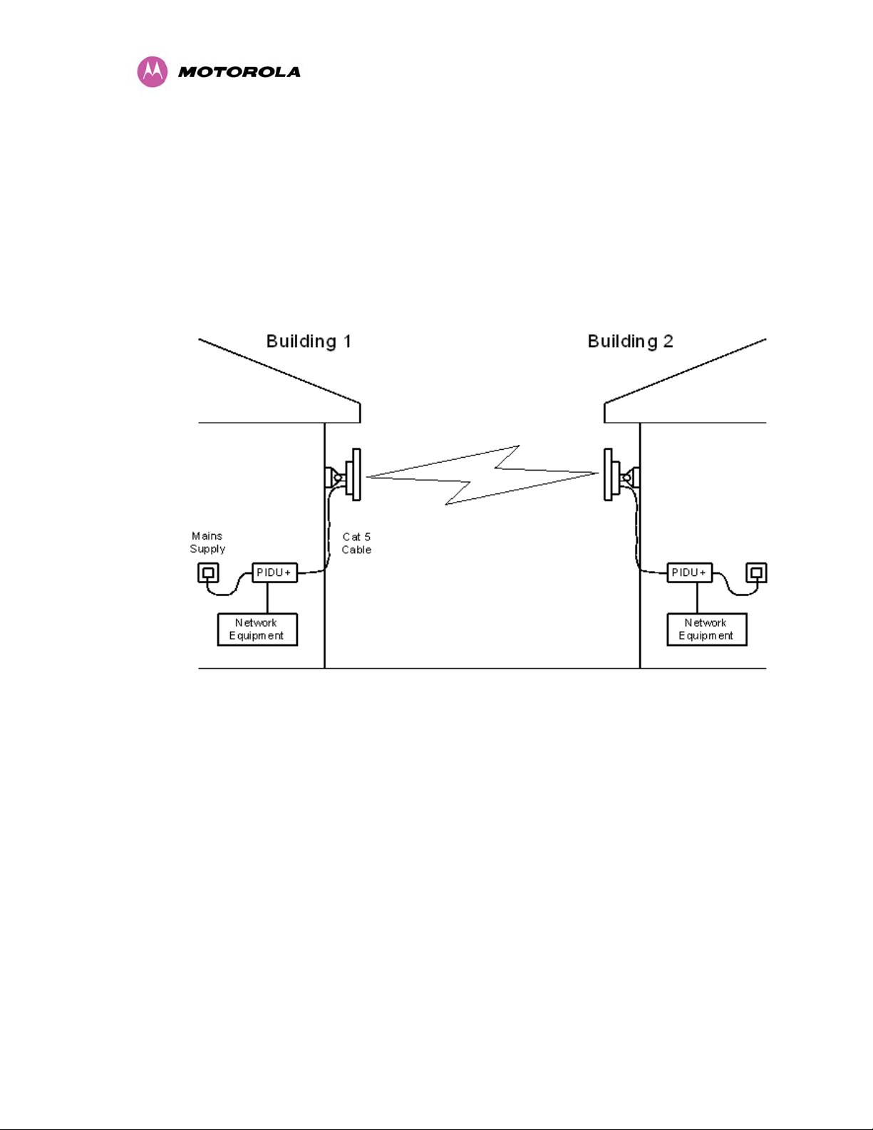
rates. The PTP 500 Series Bridge is aimed at a wide range of applications. An example
application is an enterprise that has a requirement to connect together the Local Area
Network (LAN) of two or more buildings as shown in Figure 1.
Figure 1 - Typical PTP 500 Series Bridge Deployment
The PTP 500 Series Bridge offers true non-line-of-sight (NLOS) operation by using a
combination of Orthogonal Frequency Division Multiplexing (OFDM) modulation and Multiple-
Input Multiple-Output (MIMO) techniques. These technologies enable the PTP 500 Series
Bridge to drive through foliage and around buildings to such an extent that almost universal
coverage can be expected at short range.
A PTP 500 Series Bridge system consists of a pair of identical devices that are deployed one
at each end of the link. At installation, the user sets up one unit as the Master and the other
as the Slave. Either unit can be configured as Master or Slave.
27

3 Getting Started
Each end of the link consists of:
• An integrated (or connectorized - see section 13) outdoor transceiver unit containing all
the radio and networking electronics hereafter referred to as the Outdoor Unit (ODU).
• An indoor connection box containing a mains power supply, status indicators and network
connection port. Hereafter referred to as the Power Indoor Unit Plus (PIDU Plus).
A pair of units is normally supplied pre-configured as a link.
The network connection to a PTP 500 Series Bridge is made via a 100BaseT Ethernet
connection. Power is provided to the ODU over the 100BaseT Ethernet connection using a
patented non-standard powering technique.
Power is fed into the PTP 500 Series Bridge PIDU Plus from the mains via a standard “figure
of eight” mains plug. Connection between the ODU and PIDU Plus is made using standard
CAT5e outdoor UV resistant cable. Connection between the PIDU Plus and the Network
Equipment is made using standard CAT5e cable.
3.3.1 The Outdoor Unit (ODU)
The ODU is a self-contained unit. It houses both radio and networking electronics. The ODU
for the PTP 500 Series Bridge should only be deployed using the supplied PTP 300/500/600
Series Bridge PIDU Plus. Figure 2 shows an installation example of a PTP 500 Series ODU.
Figure 2 – PTP 500 Series Bridge Outdoor Unit (ODU) with PTP-LPU
28
 Loading...