

Cambium Networks 58100 User Guide

PTP 59600 reference information Chapter 4 Reference information
PTP 59600 reference information
This section contains reference information that is specific to the PTP 59600 frequency
variant.
PTP 59600 examples of regulatory limits
Table 4-57 shows how the regulatory limits currently apply in specific countries.
Operators should note that regulations are subject to change.
Table 4-57 PTP 59600 examples of regulatory limits
Region Examples of Regulatory Limits at 5.9 GHz
Russia
India
Operation of this product is only allowed with a License Key for Region 16
(no power limit)
Operation of this product is only allowed with a License Key for Regions 17
or 19 (36 dBm or 4W EIRP at 30 MHz, 15 MHz and 10 MHz; and 33 dBm or
2 W EIRP at 5 MHz channel bandwidth).
phn-0896_009v003
4-90
UNDER DEVELOPMENT
Feb 2010

User Guide: PTP 600 Series PTP 59600 reference information
PTP 59600 licenses and region codes
PTP 59600 units may be operated in any of the regions listed in Table 4-58. When
shipped, PTP 59600 units are configured with a license key for region code 16. An
alternative license key is provided in the
17. For any other permitted region, obtain a new license key from the reseller or
distributor.
Table 4-58 PTP 59600 licenses and region codes
PTP 600 Installation Guide
for region code
Region
code
15 Unrestricted 5825 - 5925
16 Russia 5825 - 5925
17
19 India 5825 - 5875
License /
Regulation
India
Frequencies DFS
5, 10, 15, 30
MHz
5, 10, 15, 30
MHz
5875 - 5925
MHz
MHz
Channel
Bandwidth
MHz
MHz
10, 15, 30
MHz
5 MHz 33 dBm
10, 15, 30
MHz
5 MHz 33 dBm
Max Power
25 dBm
25 dBm
36 dBm
EIRP
EIRP
36 dBm
EIRP
EIRP
NOTE
The 5.8 GHz license for India is addressed using both PTP 58600 and PTP
59600 frequency variants.
phn-0896_009v003
Feb 2010
UNDER DEVELOPMENT
4-91

PTP 59600 reference information Chapter 4 Reference information
PTP 59600 regulatory compliance
Russia
This system has been tested for type approval in Russia of fixed link equipment under
the heading of BPD TZS 12.
Сертификат соответствия Срок действия
ОС-1-РД-0241 с 28 октября 2008 г.
PTP 59600 radio system specifications
Table 4-59 contains radio system specifications for the PTP 59600.
Table 4-59 PTP 59600 RF specifications
Radio Technology Specification
RF Band 5.825-5.925GHz
By dynamic frequency control and manual intervention
Channel Selection
Dynamic Frequency Control
Channel size 5, 10, 15 and 30 MHz
Manual Power Control
Receiver Noise Figure Typically 6 dB
Antenna Type Integrated flat plate antenna
Automatic detection on start-up and continual adaptation
to avoid interference.
Initial capture 10-15 sec. Out of service on interference
100 ms.
Maximum power can be controlled lower than the power
limits shown above in order to control interference to
other users of the band.
Antenna Gain 23 dBi typical
Antenna Beamwidth 8 Degrees
phn-0896_009v003
4-92
UNDER DEVELOPMENT
Feb 2010

User Guide: PTP 600 Series PTP 59600 reference information
Radio Technology Specification
Max Path Loss (5 MHz
Channel)
Duplex Scheme Symmetric fixed, asymmetric fixed or adaptive TDD
Range
Over-the-Air Encryption Proprietary scrambling mechanism.
Weather Sensitivity
Error Correction FEC
166 dB
125 miles (200km) optical line-of-sight
6 miles (10km) non-line-of-sight
Sensitivity at higher modes may be reduced during high
winds through trees due to Adaptive Modulation
Threshold changes
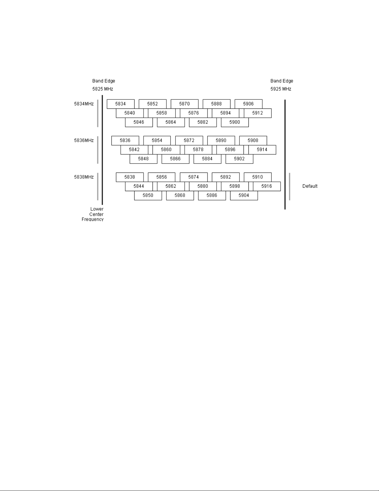
PTP 59600 available spectrum settings
The available spectrum settings for the PTP 59600 are illustrated in this section.
Adjustment of the lower centre frequency allows the operator to slide the available
frequency settings up and down the 5.9 GHz band in steps of 2 MHz.
In the 30 MHz channel bandwidth (Figure 4-26) the PTP 5
10 MHz channel raster. In the 15 MHz (Figure 4-27), 10 MHz (Figure 4-28) and
(Figure 4-29) channel bandwidt
channel raster. The channel raster is set to even centre frequencies.
NOTE
The PTP 59600 product variant does not apply any band edge power reduction.
phn-0896_009v003
Feb 2010
9600 variant operates on a
5 MHz
hs, the PTP 59600 variant operates on a 6 MHz
These tables contain data for one typical region code. The specified channel
centre frequencies may not be available in other region codes.
UNDER DEVELOPMENT
4-93

PTP 59600 reference information Chapter 4 Reference information
Figure 4-26 PTP 59600 available spectrum in 30 MHz channel bandwidth
4-94
phn-0896_009v003
UNDER DEVELOPMENT
Feb 2010
User Guide: PTP 600 Series PTP 59600 reference information
Figure 4-27 PTP 59600 available spectrum in 15 MHz channel bandwidth
phn-0896_009v003
Feb 2010
UNDER DEVELOPMENT
4-95

PTP 59600 reference information Chapter 4 Reference information
Figure 4-28 PTP 59600 available spectrum in 10 MHz channel bandwidth
Figure 4-29 PTP 59600 available spectrum in 5 MHz channel bandwidth
phn-0896_009v003
4-96
UNDER DEVELOPMENT
Feb 2010

User Guide: PTP 600 Series PTP 59600 reference information
PTP 59600 system threshold, output power and link loss
PTP 59600 system threshold figures are given in Table 4-60 (IP mode) and Table 4-61
(TDM mode). These figures assume that antenna gain is 23 dBi.
Table 4-60 PTP 59600 - IP mode - threshold, power and loss per modulation mode
Output
Threshold Value (dBm)
Power
(dBm)
Maximum Link Loss (dB)
Channel
Bandwidth
Modulation
Mode
BPSK 0.63 single
QPSK 0.63 single
QPSK 0.87 single
16QAM 0.63 single
16QAM 0.63 dual
16QAM 0.87 single
16QAM 0.87 dual
64QAM 0.75 single
64QAM 0.75 dual
64QAM 0.92 single
64 QAM 0.92 dual
5
MHz
-97.1 -94.1 -92.0 -88.7 +25.0 168.1 165.1 163.0 159.7
-90.7 -88.1 -87.1 -82.5 +24.0 160.7 158.1 157.1 152.5
-87.2 -84.4 -83.5 -79.3 +23.0 156.2 153.4 152.5 148.3
-85.0 -81.9 -81.2 -77.1 +22.0 153.0 149.9 149.2 145.1
-81.9 -78.8 -77.5 -73.5 +22.0 149.9 146.8 145.5 141.5
-80.9 -78.0 -76.7 -72.9 +20.0 146.9 143.9 142.7 138.9
-76.5 -73.9 -73.2 -70.0 +20.0 142.5 139.9 139.2 136.0
-77.0 -74.6 -73.6 -70.3 +18.0 141.0 138.6 137.6 134.3
-73.1 -71.0 -70.4 -67.5 +18.0 137.1 135.0 134.4 131.5
-72.1 -71.0 -68.9 -65.7 +18.0 136.1 135.0 132.9 129.7
-70.2 -67.2 -66.1 -62.1 +18.0 134.2 131.1 130.1 126.1
10
MHz
15
MHz
30
MH
z
All
Bands 5 MHz
10
MHz
15
MHz
30
MHz
256QAM 0.81 single
256QAM 0.81 dual
N/A N/A N/A -63.9 +18.0 N/A N/A N/A 127.9
N/A N/A N/A -59.9 +18.0 N/A N/A N/A 123.9
phn-0896_009v003
Feb 2010
UNDER DEVELOPMENT
4-97
PTP 59600 reference information Chapter 4 Reference information
Table 4-61 PTP 59600 - TDM mode - threshold, power and loss per modulation mode
Output
Threshold Value (dBm)
Power
(dBm)
Maximum Link Loss (dB)
Channel
Bandwidth
Modulation
Mode
BPSK 0.63 single
QPSK 0.63 single
QPSK 0.87 single
16QAM 0.63 single
16QAM 0.63 dual
16QAM 0.87 single
16QAM 0.87 dual
64QAM 0.75 single
64QAM 0.75 dual
64QAM 0.92 single
64 QAM 0.92 dual
5
MHz
-97.1 -94.1 -92.0 -88.7 +25.0 168.1 165.1 163.0 159.7
-88.5 -86.1 -84.4 -79.4 +24.0 158.5 156.1 154.4 149.4
-84.6 -81.9 -80.1 -76.0 +23.0 153.6 150.9 149.1 145.0
-82.5 -79.6 -77.8 -73.7 +22.0 150.4 147.6 145.8 141.7
-78.8 -76.0 -74.1 -70.4 +22.0 146.8 144.0 142.1 138.4
-78.3 -75.1 -73.7 -70.2 +20.0 144.3 141.1 139.7 136.2
-74.2 -71.6 -70.2 -66.9 +20.0 140.2 137.6 134.2 132.9
-74.7 -71.4 -70.2 -67.3 +18.0 138.7 135.4 134.2 131.3
-70.9 -68.3 -66.8 -63.6 +18.0 134.8 132.2 130.8 127.6
-71.2 -68.1 -67.0 -63.3 +18.0 135.2 132.0 131.0 127.3
-66.7 -64.2 -62.7 -58.7 +18.0 130.7 128.2 126.7 122.7
10
MHz
15
MHz
30
MH
z
All
Bands 5 MHz
10
MHz
15
MHz
30
MHz
256QAM 0.81 single
256QAM 0.81 dual
N/A N/A N/A -63.3 +18.0 N/A N/A N/A 127.3
N/A N/A N/A -58.7 +18.0 N/A N/A N/A 122.7
phn-0896_009v003
4-98
UNDER DEVELOPMENT
Feb 2010

User Guide: PTP 600 Series Data rate calculations
Data rate calculations
This section provides instructions, tables and graphs to allow calculation of the data
rate capacity that can be provided by alternative PTP 600 configurations.
The following topics are described in this section:
• Data rate defined on
• Calculation procedure and example on
• Data throughput capacity on
• Range adjustment curves on pag
Data rate defined
The data rate capacity of a PTP link is defined as the maximum end-to-end Ethernet
throughput (including Ethernet headers) that it can support. It is assumed that
Ethernet frames are 1500 octet. Data rate capacity is determined by the following
factors:
• Product variant (PTP 600 Full or Lite)
• Link Symmetry
• Link Mode Optimization (IP or TDM)
• Modulation Mode
• Channel Bandwidth
• Link Range
page 4-99
page 4-99
page 4-102
e 4-113
Calculation procedure and example
Procedure
To calculate the data rate capacity of a PTP 600 link, perform Procedure 4-1.
phn-0896_009v003
Feb 2010
UNDER DEVELOPMENT
4-99

Data rate calculations Chapter 4 Reference information
Procedure 4-1 Calculating data rate capacity
1
2
3
Use the tables in
data throughput capacity rates (Tx, Rx and Both) for the required
combination of:
The tables contain data rates for PTP 600 Full only. If the ODUs are PTP
600 Lite, divide the data rates by 2.
The tables contain data rates for links of zero range. Use the curves in
Data throughput capacity on page 4-102 to look up the
• Link Symmetry
• Link Mode Optimization
• Modulation Mode
• Channel Bandwidth
Range adjustment curves on page 4-113 to look up the Throughput
Factor that must be applied to adjust the data rates for the actual range of
the link.
4
Multiply the data rates by the Throughput Factor to give the throughput
capacity of the link.
4-100
NOTE
There is a small difference between the rates for IP and TDM because there
is fragmentation in TDM (for low priority traffic) which causes the
throughput to be reduced buy approximately 1% compared to the IP mode.
phn-0896_009v003
UNDER DEVELOPMENT
Feb 2010

User Guide: PTP 600 Series Data rate calculations
Example
Suppose that the link characteristics are:
• Product variant = PTP 600 Lite
• Link Symmetry = 1:1
• Link Mode Optimization = TDM
• Modulation Mode = 64QAM 0.92 Dual
• Channel Bandwidth = 10 MHz
• Link Range = 60 km
The calculation procedure for this example is described in Procedure 4-2.
Proce
dure 4-2 Example of data rate capacity calculation
Table 4-63 to look up the data throughput capacity rates:
1
2
3
4
Use
• Tx = 41.41 Mbits/s
• Rx = 41.41 Mbits/s
• Both = 82.81 Mbits/s
Divide these rates by 2 to give PTP 600 Lite rates:
• Tx = 20.70 Mbits/s
• Rx = 20.70 Mbits/s
• Both = 41.40 Mbits/s
Figure 4-38 to look up the Throughput Factor for 1:1, TDM and Link
Use
Range 60 km. The factor is 0.86.
Multiply the rates from Step 2 by the Throughput Factor from Step 3 to
give the throughput capacity of the link:
• Tx = 17.80 Mbits/s
• Rx = 17.80 Mbits/s
• Both = 35.60 Mbits/s
phn-0896_009v003
Feb 2010
UNDER DEVELOPMENT
4-101
 Loading...