

Cambium Networks 50670 Users manual

F
Cambium
PTP 670 Series
User Guide
System Release 670-02-51

Accuracy
While reasonable efforts have been made to assure the accuracy of this document, Cambium
Networks assumes no liability resulting from any inaccuracies or omissions in this document, or
from use of the information obtained herein. Cambium reserves the right to make changes to any
products described herein to improve reliability, function, or design, and reserves the right to revise
this document and to make changes from time to time in content hereof with no obligation to notify
any person of revisions or changes. Cambium does not assume any liability arising out of the
application or use of any product, software, or circuit described herein; neither does it convey
license under its patent rights or the rights of others. It is possible that this publication may contain
references to, or information about Cambium products (machines and programs), programming, or
services that are not announced in your country. Such references or information must not be
construed to mean that Cambium intends to announce such Cambium products, programming, or
services in your country.
Copyrights
This document, Cambium products, and 3rd Party software products described in this document
may include or describe copyrighted Cambium and other 3
stored in semiconductor memories or other media. Laws in the United States and other countries
preserve for Cambium, its licensors, and other 3
rd
Party supplied software certain exclusive rights
rd
Party supplied computer programs
for copyrighted material, including the exclusive right to copy, reproduce in any form, distribute
and make derivative works of the copyrighted material. Accordingly, any copyrighted material of
Cambium, its licensors, or the 3
rd
Party software supplied material contained in the Cambium
products described in this document may not be copied, reproduced, reverse engineered,
distributed, merged or modified in any manner without the express written permission of
Cambium. Furthermore, the purchase of Cambium products shall not be deemed to grant either
directly or by implication, estoppel, or otherwise, any license under the copyrights, patents or
patent applications of Cambium or other 3rd Party supplied software, except for the normal nonexclusive, royalty free license to use that arises by operation of law in the sale of a product.
Restrictions
Software and documentation are copyrighted materials. Making unauthorized copies is prohibited
by law. No part of the software or documentation may be reproduced, transmitted, transcribed,
stored in a retrieval system, or translated into any language or computer language, in any form or
by any means, without prior written permission of Cambium.
License Agreements
The software described in this document is the property of Cambium and its licensors. It is
furnished by express license agreement only and may be used only in accordance with the terms of
such an agreement.
High Risk Materials
Cambium and its supplier(s) specifically disclaim any express or implied warranty of fitness for any
high risk activities or uses of its products including, but not limited to, the operation of nuclear
facilities, aircraft navigation or aircraft communication systems, air traffic control, life support, or
weapons systems (“High Risk Use”). Any High Risk is unauthorized, is made at your own risk and
you shall be responsible for any and all losses, damage or claims arising out of any High Risk Use.
© 2017 Cambium Networks Limited. All Rights Reserved.
phn-4431_004v001 (October 2017)

Contents
About This User Guide ....................................................................................................................... 1
Contacting Cambium Networks .............................................................................................. 1
Purpose ..................................................................................................................................... 2
Cross references ....................................................................................................................... 2
Feedback ................................................................................................................................... 2
Important regulatory information .................................................................................................. 3
Complying with rules for the country of operation .............................................................. 3
Radar avoidance ....................................................................................................................... 3
USA specific information......................................................................................................... 3
Canada specific information ................................................................................................... 4
Renseignements specifiques au Canada ............................................................................... 5
EU specific information ........................................................................................................... 5
EU Declaration of Conformity ................................................................................................. 5
Application firmware ............................................................................................................... 6
Specific expertise and training for professional installers ................................................... 6
External antennas ..................................................................................................................... 6
Antennas externes ................................................................................................................... 6
Ethernet networking skills ....................................................................................................... 6
Lightning protection ................................................................................................................. 7
Training ..................................................................................................................................... 7
Problems and warranty .................................................................................................................. 8
Reporting problems ................................................................................................................. 8
Repair and service .................................................................................................................... 8
Hardware warranty .................................................................................................................. 8
Security advice ................................................................................................................................ 9
Warnings, cautions, and notes .................................................................................................... 10
Warnings ................................................................................................................................. 10
Cautions .................................................................................................................................. 10
Notes ....................................................................................................................................... 10
Caring for the environment .......................................................................................................... 11
In EU countries ....................................................................................................................... 11
In non-EU countries ............................................................................................................... 11
Chapter 1: Product description ................................................................................................... 1-1
Overview of the PTP 670 Series .................................................................................................. 1-2
Purpose .................................................................................................................................. 1-2
Key features ........................................................................................................................... 1-2
Frequency bands ................................................................................................................... 1-3
Typical bridge deployment .................................................................................................. 1-4
Hardware overview ............................................................................................................... 1-5
Wireless operation ....................................................................................................................... 1-7
Wireless topology ................................................................................................................. 1-7
Page i

Contents
Time division duplexing in PTP wireless topology ............................................................ 1-8
Time division duplexing in HCMP wireless topology ...................................................... 1-10
Link mode optimization ...................................................................................................... 1-12
Link symmetry ..................................................................................................................... 1-13
OFDM and channel bandwidth .......................................................................................... 1-15
Spectrum management ...................................................................................................... 1-16
Adaptive modulation .......................................................................................................... 1-17
MIMO .................................................................................................................................... 1-18
Dynamic spectrum optimization ........................................................................................ 1-19
Radar avoidance .................................................................................................................. 1-19
Access method .................................................................................................................... 1-20
Wireless encryption ............................................................................................................ 1-21
TLS RSA ............................................................................................................................... 1-22
TLS PSK 128-bit and TLS PSK 256-bit ............................................................................... 1-23
Over the air rekeying ........................................................................................................... 1-24
License keys and regulatory bands ................................................................................... 1-24
Designing PTP networks ..................................................................................................... 1-25
TDD synchronization ........................................................................................................... 1-26
Ethernet bridging ....................................................................................................................... 1-30
Ethernet ports ...................................................................................................................... 1-30
Data and management services ........................................................................................ 1-30
Ethernet switching .............................................................................................................. 1-31
Data Service ......................................................................................................................... 1-32
Second Data Service ........................................................................................................... 1-34
Out-of-Band Management Service .................................................................................... 1-36
Ethernet loopback mode..................................................................................................... 1-37
Protocol model for PTP topology ...................................................................................... 1-38
Synchronous Ethernet ........................................................................................................ 1-40
IEEE 1588-2008 Transparent Clock .................................................................................... 1-42
TDM bridging.............................................................................................................................. 1-43
TDM description .................................................................................................................. 1-43
Lowest TDM modulation mode ......................................................................................... 1-44
Fixed frequency operation ................................................................................................. 1-44
Ethernet cables for TDM ..................................................................................................... 1-45
Further reading .................................................................................................................... 1-45
System management ................................................................................................................. 1-46
Management agent ............................................................................................................. 1-46
Network management ........................................................................................................ 1-47
IPv6 ....................................................................................................................................... 1-48
Web server ........................................................................................................................... 1-50
RADIUS authentication ....................................................................................................... 1-52
SNMP.................................................................................................................................... 1-53
Simple Network Time Protocol (SNTP) ............................................................................. 1-53
SNMPv3 security ................................................................................................................. 1-54
System logging (syslog) ..................................................................................................... 1-57
AES license .......................................................................................................................... 1-57
Page ii

Contents
Critical security parameters ............................................................................................... 1-58
Software upgrade ................................................................................................................ 1-59
Capability upgrades ............................................................................................................ 1-60
Recovery mode .................................................................................................................... 1-60
Chapter 2: System hardware ...................................................................................................... 2-1
Outdoor unit (ODU) ..................................................................................................................... 2-2
ODU description .................................................................................................................... 2-2
PTP 670 Integrated ODU ....................................................................................................... 2-3
PTP 670 Connectorized ODU ................................................................................................ 2-5
ODU capability upgrades ..................................................................................................... 2-7
ODU accessories ................................................................................................................... 2-8
ODU mounting brackets ....................................................................................................... 2-8
ODU interfaces ...................................................................................................................... 2-9
ODU specifications .............................................................................................................. 2-11
Power supply units (PSU) .......................................................................................................... 2-12
PSU description ................................................................................................................... 2-12
PSU part numbers ............................................................................................................... 2-15
AC Power Injector 56V interfaces ...................................................................................... 2-16
AC+DC Enhanced Power Injector 56V interfaces ............................................................. 2-17
CMM5 Power and Sync Injector interfaces ....................................................................... 2-18
PSU specifications ............................................................................................................... 2-19
Antennas and antenna cabling ................................................................................................. 2-21
Antenna requirements ........................................................................................................ 2-21
RF cable and connectors .................................................................................................... 2-21
Antenna accessories ........................................................................................................... 2-22
FCC approved antennas...................................................................................................... 2-22
ISEDC approved antennas .................................................................................................. 2-25
Antennes approuvées par ISDEC ....................................................................................... 2-26
Ethernet cabling ......................................................................................................................... 2-30
Ethernet standards and cable lengths ............................................................................... 2-30
Outdoor copper Cat5e Ethernet cable ............................................................................... 2-31
Cable grounding kit ............................................................................................................. 2-32
Lightning protection unit (LPU) and grounding kit .......................................................... 2-33
LPU for GPS drop cables .................................................................................................... 2-34
RJ45 connectors and spare glands .................................................................................... 2-35
Cable hoisting grip .............................................................................................................. 2-35
Indoor Cat5e cable .............................................................................................................. 2-36
SFP module kits ................................................................................................................... 2-36
Optical cable and connectors ............................................................................................. 2-38
PTP-SYNC unit ............................................................................................................................ 2-39
PTP-SYNC unit description ................................................................................................. 2-39
PTP-SYNC part numbers .................................................................................................... 2-40
PTP-SYNC unit interfaces ................................................................................................... 2-41
PTP-SYNC specifications .................................................................................................... 2-42
GPS receivers ............................................................................................................................. 2-45
Trimble Acutime™ GG GPS receiver for PTP-SYNC ........................................................ 2-45
Page iii

Contents
Universal GPS ...................................................................................................................... 2-46
Network indoor unit (NIDU) ...................................................................................................... 2-47
NIDU description ................................................................................................................. 2-47
NIDU part numbers ............................................................................................................. 2-48
NIDU interfaces ................................................................................................................... 2-48
NIDU specifications ............................................................................................................. 2-49
Chapter 3: System planning ....................................................................................................... 3-1
Typical deployment ..................................................................................................................... 3-2
ODU with POE interface to PSU ........................................................................................... 3-2
E1 or T1 interfaces ................................................................................................................. 3-5
SFP and Aux Ethernet interfaces ......................................................................................... 3-6
GPS receiver interfaces......................................................................................................... 3-9
Site planning............................................................................................................................... 3-11
Grounding and lightning protection .................................................................................. 3-11
Lightning protection zones ................................................................................................. 3-11
Site grounding system ........................................................................................................ 3-12
ODU and external antenna location .................................................................................. 3-13
ODU ambient temperature limits ...................................................................................... 3-13
ODU wind loading ............................................................................................................... 3-14
Hazardous locations ............................................................................................................ 3-14
PSU DC power supply ......................................................................................................... 3-15
PSU AC power supply ......................................................................................................... 3-15
PSU location ........................................................................................................................ 3-15
PTP-SYNC location .............................................................................................................. 3-15
GPS receiver location .......................................................................................................... 3-15
NIDU location ...................................................................................................................... 3-16
Drop cable grounding points ............................................................................................. 3-17
LPU location ......................................................................................................................... 3-17
Multiple LPUs ...................................................................................................................... 3-17
Radio spectrum planning .......................................................................................................... 3-20
General wireless specifications ......................................................................................... 3-20
Regulatory limits ................................................................................................................. 3-21
Conforming to the limits..................................................................................................... 3-22
Available spectrum ............................................................................................................. 3-22
Channel bandwidth ............................................................................................................. 3-22
Frequency selection ............................................................................................................ 3-22
Link planning .............................................................................................................................. 3-24
LINKPlanner ......................................................................................................................... 3-24
Range and obstacles ........................................................................................................... 3-24
LINKPlanner for synchronized networks ........................................................................... 3-25
Path loss ............................................................................................................................... 3-25
Adaptive modulation .......................................................................................................... 3-25
Calculating data rate capacity ............................................................................................ 3-26
Planning for connectorized units .............................................................................................. 3-29
When to install connectorized units .................................................................................. 3-29
Choosing external antennas .............................................................................................. 3-29
Page iv

Contents
Calculating RF cable length (5.8 GHz FCC only) ............................................................... 3-30
Configuration options for TDD synchronization ..................................................................... 3-31
Using PTP-SYNC ................................................................................................................. 3-31
Using CMM5 ........................................................................................................................ 3-35
Using a direct connection between ODUs ........................................................................ 3-35
Data network planning .............................................................................................................. 3-36
Ethernet interfaces .............................................................................................................. 3-36
Layer two control protocols ............................................................................................... 3-36
Ethernet port allocation for PTP topology ........................................................................ 3-37
Ethernet port allocation for HCMP topology .................................................................... 3-46
VLAN membership .............................................................................................................. 3-50
Priority for management traffic ......................................................................................... 3-50
IP interface ........................................................................................................................... 3-50
Quality of service for bridged Ethernet traffic .................................................................. 3-51
“Daisy-chaining” PTP 670 links ......................................................................................... 3-52
Green Ethernet switches..................................................................................................... 3-52
TDM network planning .............................................................................................................. 3-53
Network management planning ............................................................................................... 3-54
Planning for SNMP operation ............................................................................................ 3-54
Supported diagnostic alarms ............................................................................................. 3-54
Enabling SNMP ................................................................................................................... 3-55
Security planning ....................................................................................................................... 3-56
Planning for SNTP operation ............................................................................................. 3-56
Using the Security Wizard .................................................................................................. 3-56
Planning for wireless encryption ....................................................................................... 3-57
Planning for HTTPS/TLS operation .................................................................................... 3-59
Planning for protocols and ports ....................................................................................... 3-60
Planning for SNMPv3 operation ........................................................................................ 3-60
Planning for RADIUS operation ......................................................................................... 3-63
System threshold, output power and link loss ........................................................................ 3-65
4.8 GHz to 5.9 GHz Frequency Variant ............................................................................... 3-66
4.9 GHz to 6.05 GHz Frequency Variant ............................................................................. 3-76
Data throughput capacity tables ............................................................................................... 3-86
Data capacity in PTP topology ........................................................................................... 3-86
Data capacity in HCMP topology ..................................................................................... 3-120
TDM traffic load ................................................................................................................. 3-127
Chapter 4: Legal and regulatory information ............................................................................ 4-1
Cambium Networks end user license agreement ..................................................................... 4-2
Definitions .............................................................................................................................. 4-2
Acceptance of this agreement ............................................................................................. 4-2
Grant of license ..................................................................................................................... 4-2
Conditions of use .................................................................................................................. 4-3
Title and restrictions ............................................................................................................. 4-4
Confidentiality ....................................................................................................................... 4-4
Right to use Cambium’s name ............................................................................................. 4-5
Transfer .................................................................................................................................. 4-5
Page v

Contents
Updates .................................................................................................................................. 4-5
Maintenance .......................................................................................................................... 4-5
Disclaimer .............................................................................................................................. 4-6
Limitation of liability ............................................................................................................. 4-6
U.S. government ................................................................................................................... 4-6
Term of license ...................................................................................................................... 4-7
Governing law ....................................................................................................................... 4-7
Assignment ............................................................................................................................ 4-7
Survival of provisions ........................................................................................................... 4-7
Entire agreement ................................................................................................................... 4-7
Third party software .............................................................................................................. 4-7
Compliance with safety standards ........................................................................................... 4-20
Electrical safety compliance ............................................................................................... 4-20
Electromagnetic compatibility (EMC) compliance ........................................................... 4-20
Human exposure to radio frequency energy .................................................................... 4-21
Compliance with radio regulations .......................................................................................... 4-26
Type approvals .................................................................................................................... 4-27
FCC compliance ................................................................................................................... 4-28
ISEDC compliance ............................................................................................................... 4-30
Chapter 5: Installation ................................................................................................................. 5-1
Safety ............................................................................................................................................ 5-2
Power lines ............................................................................................................................ 5-2
Working at heights ................................................................................................................ 5-2
PSU ......................................................................................................................................... 5-2
Grounding and protective earth .......................................................................................... 5-2
AC supply ............................................................................................................................... 5-2
DC supply ............................................................................................................................... 5-3
Powering down before servicing ......................................................................................... 5-3
Primary disconnect device ................................................................................................... 5-3
External cables ...................................................................................................................... 5-3
Drop cable tester ................................................................................................................... 5-3
Grounding PTP-SYNC ........................................................................................................... 5-3
RF exposure near the antenna ............................................................................................. 5-3
Minimum separation distances ........................................................................................... 5-4
Grounding and lightning protection requirements ............................................................ 5-4
Grounding cable installation methods ................................................................................ 5-4
Siting ODUs and antennas ................................................................................................... 5-4
Thermal Safety ...................................................................................................................... 5-4
ODU variants and mounting bracket options ............................................................................ 5-6
Installing the ODU and top LPU .................................................................................................. 5-7
Attach ground cables to the ODU ........................................................................................ 5-7
Mount the ODU on the mast ................................................................................................ 5-7
Mount the top LPU .............................................................................................................. 5-10
Interconnect and ground the ODU and top LPU .............................................................. 5-10
Install external antennas for a Connectorized ODU ................................................................ 5-12
Installing the copper Cat5e Ethernet interface ........................................................................ 5-14
Page vi

Contents
Install the ODU to top LPU drop cable .............................................................................. 5-14
Install the main drop cable ................................................................................................. 5-16
Install the bottom LPU to PSU drop cable ........................................................................ 5-19
Test resistance in the drop cable ....................................................................................... 5-21
Installing the PSU ....................................................................................................................... 5-22
Installing the AC Power Injector 56V ................................................................................. 5-22
Installing the AC+DC Enhanced Power Injector 56V ........................................................ 5-23
Installing the CMM5 ............................................................................................................ 5-24
Installing a PTP-SYNC unit ........................................................................................................ 5-25
Mounting the PTP-SYNC unit ............................................................................................. 5-25
Connecting up the PTP-SYNC unit .................................................................................... 5-26
Powering up the PTP-SYNC installation ........................................................................... 5-28
Installing the Trimble Accutime GPS receiver ......................................................................... 5-29
Mounting the GPS receiver ................................................................................................ 5-29
Preparing the GPS drop cable ............................................................................................ 5-29
Assembling an RJ45 plug and housing for GPS .............................................................. 5-30
Assembling a 12 way circular connector .......................................................................... 5-32
Connecting the GPS drop cable ......................................................................................... 5-36
Top grounding point for GPS adapter cable..................................................................... 5-36
Installing and connecting the GPS LPU ............................................................................ 5-38
Installing a NIDU ........................................................................................................................ 5-39
Mounting the NIDU ............................................................................................................. 5-39
Connecting the NIDU to the PSU, LAN and TDM cables ................................................. 5-40
Connecting the NIDU to a DC power supply .................................................................... 5-42
Installing an SFP Ethernet interface ......................................................................................... 5-45
Fitting the long cable gland ................................................................................................ 5-47
Inserting the SFP module ................................................................................................... 5-48
Connecting the cable .......................................................................................................... 5-50
Fitting the gland .................................................................................................................. 5-51
Removing the cable and SFP module ............................................................................... 5-53
Installing an Aux Ethernet interface ......................................................................................... 5-54
Supplemental installation information .................................................................................... 5-55
Stripping drop cable ........................................................................................................... 5-55
Creating a drop cable grounding point ............................................................................. 5-56
Weatherproofing an N type connector .............................................................................. 5-59
Replacing PSU fuses ........................................................................................................... 5-62
Chapter 6: Configuration and alignment ................................................................................... 6-1
Preparing for configuration and alignment ............................................................................... 6-2
Safety precautions ................................................................................................................ 6-2
Regulatory compliance ......................................................................................................... 6-2
Selecting configuration options ........................................................................................... 6-2
Generating license keys ........................................................................................................ 6-3
Connecting to the unit ................................................................................................................. 6-4
Configuring the management PC ........................................................................................ 6-4
Connecting to the PC and powering up .............................................................................. 6-5
Using the web interface ............................................................................................................... 6-6
Page vii

Contents
Logging into the web interface ............................................................................................ 6-6
Using the menu options ....................................................................................................... 6-7
Installation menu ......................................................................................................................... 6-9
Starting the Installation Wizard ........................................................................................... 6-9
Disarm Installation page ..................................................................................................... 6-10
Current Installation Summary page .................................................................................. 6-10
Software License Key page ................................................................................................ 6-13
Wireless Topology Configuration page ............................................................................ 6-15
Interface Configuration page ............................................................................................. 6-16
Wireless Configuration page .............................................................................................. 6-25
TDD Frame page .................................................................................................................. 6-32
TDD synchronization page (optional) ................................................................................ 6-33
Confirm Installation Configuration page ........................................................................... 6-38
System menu.............................................................................................................................. 6-39
System Configuration page ............................................................................................... 6-39
LAN Configuration page ..................................................................................................... 6-43
QoS Configuration page ..................................................................................................... 6-56
SFP Configuration page ...................................................................................................... 6-59
TDM Configuration page .................................................................................................... 6-62
Authorization Control page ................................................................................................ 6-63
Save and Restore Configuration page .............................................................................. 6-64
Reset Configuration page ................................................................................................... 6-67
Further reading .................................................................................................................... 6-68
Software Upgrade page...................................................................................................... 6-68
Management menu .................................................................................................................... 6-70
Web-Based Management page .......................................................................................... 6-70
Local User Accounts page .................................................................................................. 6-72
RADIUS Configuration page .............................................................................................. 6-77
Webpage Properties page .................................................................................................. 6-78
Email Configuration page ................................................................................................... 6-81
Diagnostic Alarms page...................................................................................................... 6-83
Time Configuration page .................................................................................................... 6-84
Syslog Configuration page ................................................................................................. 6-88
SNMP pages (for SNMPv3) ....................................................................................................... 6-90
Current SNMP Summary (for SNMPv3) ............................................................................ 6-90
Step 1: SNMP Configuration (for SNMPv3) ...................................................................... 6-91
Step 2: SNMP MIB-II System Objects (for SNMPv3) ........................................................ 6-93
Step 3: SNMP User Policy Configuration (for SNMPv3) .................................................. 6-94
Step 4: SNMP User Accounts Configuration (for SNMPv3) ............................................ 6-95
Step 5: SNMP Trap Configuration (for SNMPv3) ............................................................. 6-96
Confirm SNMP Configuration (for SNMPv3) .................................................................... 6-98
SNMP pages (for SNMPv1/2c) .................................................................................................. 6-99
Current SNMP Summary (for SNMPv1/2c) ....................................................................... 6-99
Step 1: SNMP Configuration (for SNMPv1/2c) ................................................................. 6-99
Step 2: SNMP MIB-II System Objects (for SNMPv1/2c) ................................................. 6-100
Step 3: SNMP Trap Configuration (for SNMPv1/2c) ...................................................... 6-101
Page viii

Contents
Confirm SNMP Configuration (for SNMPv1/2c) ............................................................. 6-102
Security menu .......................................................................................................................... 6-103
Preparation ........................................................................................................................ 6-103
Security Configuration Wizard page ............................................................................... 6-103
Security options ................................................................................................................ 6-104
Key of Keys ........................................................................................................................ 6-105
Entropy ............................................................................................................................... 6-106
Enter User Security Banner .............................................................................................. 6-107
Enter Login Information Settings .................................................................................... 6-108
Enter HTTPS Configuration .............................................................................................. 6-109
Configure Wireless Security ............................................................................................. 6-110
HTTP and Telnet options .................................................................................................. 6-113
Confirm Security Configuration ....................................................................................... 6-115
Zeroize CSPs page ............................................................................................................. 6-117
Aligning antennas .................................................................................................................... 6-118
Starting up the units ......................................................................................................... 6-118
Checking that the units are armed ................................................................................... 6-118
Aligning antennas ............................................................................................................. 6-119
Aligning separate antennas for spatial diversity ............................................................ 6-120
ODU installation tones ...................................................................................................... 6-121
Graphical Install page ....................................................................................................... 6-123
Disarming the units ........................................................................................................... 6-124
Comparing actual to predicted performance ................................................................. 6-125
Other configuration tasks ........................................................................................................ 6-126
Connecting to the network ............................................................................................... 6-126
Upgrading software using TFTP ...................................................................................... 6-127
Chapter 7: Operation ................................................................................................................... 7-1
System summary and status ...................................................................................................... 7-2
System Summary page ........................................................................................................ 7-2
System Status page .............................................................................................................. 7-3
Rebooting and logging out ....................................................................................................... 7-18
Login Information page ...................................................................................................... 7-18
Reboot Wireless Unit page ................................................................................................. 7-18
Change Password page ...................................................................................................... 7-19
Logging out .......................................................................................................................... 7-19
Alarms, alerts and messages .................................................................................................... 7-20
Alarms .................................................................................................................................. 7-20
Email alerts .......................................................................................................................... 7-24
Syslog page ......................................................................................................................... 7-25
Format of syslog server messages .................................................................................... 7-25
Configuration and status messages .................................................................................. 7-26
Event messages ................................................................................................................... 7-26
Spectrum Management ............................................................................................................. 7-29
Spectrum Expert and Spectrum Management pages ..................................................... 7-29
Spectrum Expert page ........................................................................................................ 7-30
Spectrum Management page ............................................................................................ 7-34
Page ix

Contents
Spectrum Management Settings ....................................................................................... 7-35
Interpreting the receive spectrum plot .............................................................................. 7-37
Barring channels ................................................................................................................. 7-43
Selecting a Channel and a Time period ............................................................................ 7-45
Interpreting the timeseries plot ......................................................................................... 7-46
Interpreting the Interference Waterfall plot ...................................................................... 7-47
Interpreting the histogram plot .......................................................................................... 7-49
Spectrum Expert example .................................................................................................. 7-50
Managing security ..................................................................................................................... 7-53
Zeroizing critical security parameters ............................................................................... 7-53
System statistics ........................................................................................................................ 7-54
System Statistics page ........................................................................................................ 7-54
Wireless Port Counters page .............................................................................................. 7-60
Main Port Counters page (PTP topology only) ................................................................. 7-63
Aux Port Counters page (PTP topology only) ................................................................... 7-66
SFP Port Counters page (PTP topology only) ................................................................... 7-66
Ethernet Port Counters page (HCMP topology only) ....................................................... 7-67
Management Counters page (HCMP topology only) ....................................................... 7-69
SyncE Status page .............................................................................................................. 7-70
Diagnostics Plotter page ..................................................................................................... 7-73
Generate Downloadable Diagnostics page....................................................................... 7-75
Recovery mode........................................................................................................................... 7-77
Entering recovery mode ..................................................................................................... 7-77
Upgrading software image................................................................................................. 7-79
Resetting IP & Ethernet configuration ............................................................................... 7-80
Resetting all configuration data ......................................................................................... 7-82
Zeroize Critical Security Parameters ................................................................................. 7-83
Rebooting the unit ............................................................................................................... 7-84
Chapter 8: Troubleshooting ........................................................................................................ 8-1
Cable Diagnostics ......................................................................................................................... 8-2
Test scenarios ........................................................................................................................ 8-2
Cable Diagnostics test ........................................................................................................... 8-3
Testing link end hardware ........................................................................................................... 8-7
AC Power Injector 56V LED sequence ................................................................................. 8-7
AC+DC Enhanced Power Injector 56V LED sequence ........................................................ 8-7
Ethernet packet test ............................................................................................................. 8-10
Testing the radio link ................................................................................................................. 8-13
No activity ............................................................................................................................ 8-13
Some activity ....................................................................................................................... 8-13
Radio and television interference ...................................................................................... 8-14
Testing PTP-SYNC ...................................................................................................................... 8-15
Checking the PTP-SYNC LEDs ............................................................................................ 8-15
LEDs do not illuminate ........................................................................................................ 8-15
STATUS LED is on steady .................................................................................................. 8-16
STATUS LED double-blinks ................................................................................................ 8-16
ODU LED does not illuminate within 90 seconds ............................................................ 8-16
Page x

Contents
ODU LED blinks red ............................................................................................................. 8-16
GPS LED does not illuminate or blink on clustered units ................................................ 8-16
Testing a TDM link ..................................................................................................................... 8-18
Checking the NIDU LEDs .................................................................................................... 8-18
Performing a TDM loopback test ....................................................................................... 8-19
Checking for 1000BASE-T operation ................................................................................. 8-19
Glossary ............................................................................................................................................... I
Page xi

About This User Guide
This guide describes the planning, installation, configuration and operation of the Cambium
PTP 670 Series of point-to-point wireless Ethernet bridges. It is intended for use by the system
designer, system installer and system administrator.
For radio network design, refer to the following chapters:
• Chapter 1: Product description
• Chapter 2: System hardware
• Chapter 3: System planning
• Chapter 4: Legal and regulatory information
For radio equipment installation, refer to the following chapter:
• Chapter 5: Installation
For system configuration, monitoring and fault-finding, refer to the following chapters:
• Chapter 6: Configuration and alignment
• Chapter 7: Operation
• Chapter 8: Troubleshooting
Contacting Cambium Networks
Support website: https://support.cambiumnetworks.com
Main website: http://www.cambiumnetworks.com
Sales enquiries: solutions@cambiumnetworks.com
Support enquiries: https://support.cambiumnetworks.com
RMA enquiries https://support.cambiumnetworks.com
Telephone number list: http://www.cambiumnetworks.com/contact-us/
Address:
Cambium Networks Limited,
Linhay Business Park,
Eastern Road,
Ashburton,
Devon, UK,
TQ13 7UP
Page 1

About This User Guide Important regulatory information
Purpose
Cambium Networks Point-To-Point (PTP) documents are intended to instruct and assist
personnel in the operation, installation and maintenance of the Cambium PTP equipment and
ancillary devices. It is recommended that all personnel engaged in such activities be properly
trained.
Cambium disclaims all liability whatsoever, implied or express, for any risk of damage, loss or
reduction in system performance arising directly or indirectly out of the failure of the customer,
or anyone acting on the customer's behalf, to abide by the instructions, system parameters, or
recommendations made in this document.
Cross references
References to external publications are shown in italics. Other cross references, emphasized in
blue text in electronic versions, are active links to the references.
This document is divided into numbered chapters that are divided into sections. Sections are
not numbered, but are individually named at the top of each page, and are listed in the table of
contents.
Feedback
We appreciate feedback from the users of our documents. This includes feedback on the
structure, content, accuracy, or completeness of our documents. Send us feedback at
https://support.cambiumnetworks.com
Page 2

About This User Guide Important regulatory information
Caution
Important regulatory information
Complying with rules for the country of operation
The PTP 670 product operates in frequency bands between 4.8 GHz and 5.9 GHz. These bands
are made available for licensed or unlicensed operation according to the individual rules and
regulations in force in each country.
Ensure that the equipment is operated in accordance with applicable regulations.
Obtain the necessary licenses or permits before using the equipment in licensed bands.
Some regional variants of PTP 670 are locked to a single country of operation. For the
remaining regional variants, use the Cambium Networks Support Centre to obtain a countryspecific license key for the country of operation. Country-specific license keys are automatically
populated with the list of regulatory bands allowed in that country.
In some regulatory bands, PTP 670 may be allowed as a secondary user of the band, where
operation is subject to the condition that the product does not cause interference to primary
users of the band. In this case, take care to avoid causing interference to primary users.
Radar avoidance
In countries where radar systems are the primary band users, the regulators have mandated
special requirements to protect these systems from interference caused by unlicensed devices.
Unlicensed devices must detect and avoid co-channel operation with radar systems.
The PTP 670 provides detect and avoid functionality for countries and frequency bands
requiring protection for radar systems.
Installers and users must meet all local regulatory requirements for radar detection. To meet
these requirements, users must install a license key for the correct country during
commissioning of the PTP 670. If this is not done, installers and users may be liable to civil and
criminal penalties.
Contact the Cambium helpdesk if more guidance is required.
USA specific information
This device complies with Part 15 of the FCC Rules. Operation is subject to the
following two conditions:
• This device may not cause harmful interference, and
• This device must accept any interference received, including interference that may
cause undesired operation.
Page 3

About This User Guide Important regulatory information
Caution
The USA Federal Communications Commission (FCC) requires manufacturers to implement
special features to prevent interference to weather radar systems that operate in the band 5600
MHz to 5650 MHz. These features must be implemented in all products able to operate
outdoors in the band 5470 MHz to 5725 MHz.
Manufacturers must ensure that such radio products cannot be configured to operate outside
of FCC rules; specifically it must not be possible to disable or modify the radar protection
functions that have been demonstrated to the FCC.
In order to comply with these FCC requirements, Cambium supplies variants of the PTP 670 for
operation in the USA. These variants are only allowed to operate with license keys that comply
with FCC rules.
Other variants of the PTP 670 are available for use in the rest of the world, but these variants
are not supplied to the USA except under strict controls, when they are needed for export and
deployment outside the USA.
Canada specific information
This device complies with Innovation, Science and Economic Development Canada’s
licence-exempt RSSs. Operation is subject to the following two conditions:
(1) This device may not cause interference; and
(2) This device must accept any interference, including interference that may cause
undesired operation of the device.
Innovation, Science and Economic Development Canada (ISEDC) requires manufacturers to
implement special features to prevent interference to weather radar systems that operate in the
band 5600 MHz to 5650 MHz. These features must be implemented in all products able to
operate outdoors in the band 5470 MHz to 5725 MHz.
Manufacturers must ensure that such radio products cannot be configured to operate outside
of ISEDC rules; specifically it must not be possible to disable or modify the radar protection
functions that have been demonstrated to ISEDC.
In order to comply with these ISEDC requirements, Cambium supplies variants of the PTP 670
for operation in Canada. These variants are only allowed to operate with license keys that
comply with ISEDC rules. In particular, operation of radio channels overlapping the band
5600 MHz to 5650 MHz is not allowed and these channels are permanently barred.
In addition, other channels may also need to be barred when operating close to weather radar
installations.
Other variants of the PTP 670 are available for use in the rest of the world, but these variants
are not supplied to Canada except under strict controls, when they are needed for export and
deployment outside Canada.
Page 4

About This User Guide Important regulatory information
Attention
Renseignements specifiques au Canada
Le présent appareil est conforme aux CNR d'Innovation, Sciences et Développement
Economique Canada applicables aux appareils radio exempts de licence.
L'exploitation est autorisée aux deux conditions suivantes :
(1) l'appareil ne doit pas produire de brouillage, et
(2) l'utilisateur de l'appareil doit accepter tout brouillage radioélectrique subi, même si
le brouillage est susceptible d'en compromettre le fonctionnement.
Innovation, Sciences et Développement Economique Canada (ISDEC) a demandé aux
fabricants de mettre en œuvre des mécanismes spécifiques pour éviter d’interférer avec des
systèmes radar fonctionnant dans la bande 5600 MHz à 5650 MHz. Ces mécanismes doivent
être mis en œuvre dans tous les produits capables de fonctionner à l'extérieur dans la bande
5470 MHz à 5725 MHz.
Les fabricants doivent s'assurer que les produits de radiocommunications ne peuvent pas être
configurés pour fonctionner en dehors des règles ISDEC, en particulier, il ne doit pas être
possible de désactiver ou modifier les fonctions de protection des radars qui ont été démontrés
à ISDEC.
Afin de se conformer à ces exigences de ISEDC, Cambium fournit des variantes du PTP 670
exclusivement pour le Canada. Ces variantes ne permettent pas à l’équipement de fonctionner
en dehors des règles de ISDEC. En particulier, le fonctionnement des canaux de radio qui
chevauchent la bande 5600-5650 MHz est interdite et ces canaux sont définitivement exclus.
EU specific information
BE BG CZ DK DE EE IE EL ES
PTP 670 can be configured to operate in lightly-licensed frequency bands and unlicensed
frequency bands that are permitted in individual countries but not harmonized within the EU.
Ensure that the equipment is operated in accordance with applicable regulations for the
country of operation. Obtain the necessary licenses or permits before using the equipment in
lightly-licensed bands.
FR HR IT CY LV LT LU HU MT
NL AT PL PT RO SI SK FI SE
UK
EU Declaration of Conformity
Hereby, Cambium Networks declares that the Cambium PTP 670 Series Wireless Ethernet
Bridge complies with the essential requirements and other relevant provisions of Directive
1999/5/EC. The declaration of conformity may be consulted at:
http://www.cambiumnetworks.com/support/compliance/
Page 5

About This User Guide Important regulatory information
Application firmware
Download the latest PTP 670 Series firmware and install it in the Outdoor Units (ODUs) before
deploying the PTP 670 equipment. Instructions for installing firmware are provided in
Upgrading software image on page 7-79.
Specific expertise and training for professional installers
To ensure that the PTP 670 is installed and configured in compliance with the requirements of
ISEDC and the FCC, installers must have the radio engineering skills and training described in
this section. This is particularly important when installing and configuring a PTP 670 system for
operation in the 5.1 GHz and 5.4 GHz UNII bands.
External antennas
When using a connectorized version of the product (as compared to the version with an
integrated antenna), the conducted transmit power may need to be reduced to ensure the
regulatory limit on transmitter EIRP is not exceeded. The installer must have an understanding
of how to compute the effective antenna gain from the actual antenna gain and the feeder
cable losses.
The range of permissible values for maximum antenna gain and feeder cable losses are
included in this user guide together with a sample calculation. The product GUI automatically
applies the correct conducted power limit to ensure that it is not possible for the installation to
exceed the EIRP limit, when the appropriate values for antenna gain and feeder cable losses
are entered into the GUI.
Antennas externes
Lorsque vous utilisez une version du produit sans antenne intégrée, il peut être nécessaire de
réduire la puissance d'émission pour garantir que la limite réglementaire de puissance isotrope
rayonnée équivalente (PIRE) n'est pas dépassée. L'installateur doit avoir une bonne
compréhension de la façon de calculer le gain de l'antenne de gain de l'antenne réelle et les
pertes dans les câbles de connections.
La plage de valeurs admissibles pour un gain maximal de l'antenne et des pertes de câbles de
connections sont inclus dans ce guide d'utilisation avec un exemple de calcul. L'interface
utilisateur du produit applique automatiquement la limite de puissance menée correct afin de
s'assurer qu'il ne soit pas possible pour l'installation de dépasser la limite PIRE, lorsque les
valeurs appropriées pour le gain d'antenne et les pertes de câbles d'alimentation sont entrées
dans l’interface utilisateur.
Ethernet networking skills
The installer must have the ability to configure IP addressing on a PC and to set up and control
products using a web browser interface.
Page 6

About This User Guide Important regulatory information
Lightning protection
To protect outdoor radio installations from the impact of lightning strikes, the installer must be
familiar with the normal procedures for site selection, bonding and grounding. Installation
guidelines for the PTP 670 can be found in Chapter 2: System hardware and Chapter 5:
Installation.
Training
The installer needs to have basic competence in radio and IP network installation. The specific
requirements applicable to the PTP 670 should be gained by reading Chapter 5: Installation and
Chapter 6: Configuration and alignment and by performing sample set ups at base workshop
before live deployments.
Page 7

About This User Guide Problems and warranty
1
2
3
4
5
Caution
Problems and warranty
Reporting problems
If any problems are encountered when installing or operating this equipment, follow this
procedure to investigate and report:
Search this document and the software release notes of supported releases.
Visit the support website.
Ask for assistance from the Cambium product supplier.
Gather information from affected units, such as any available diagnostic downloads.
Escalate the problem by emailing or telephoning support.
Repair and service
If unit failure is suspected, obtain details of the Return Material Authorization (RMA) process
from the support website.
Hardware warranty
Cambium’s standard hardware warranty is for one (1) year from date of shipment from
Cambium Networks or a Cambium distributor. Cambium Networks warrants that hardware will
conform to the relevant published specifications and will be free from material defects in
material and workmanship under normal use and service. Cambium shall within this time, at its
own option, either repair or replace the defective product within thirty (30) days of receipt of
the defective product. Repaired or replaced product will be subject to the original warranty
period but not less than thirty (30) days.
To register PTP products or activate warranties, visit the support website. For warranty
assistance, contact the reseller or distributor.
Using non-Cambium parts for repair could damage the equipment or void warranty.
Contact Cambium for service and repair instructions.
Portions of Cambium equipment may be damaged from exposure to electrostatic
discharge. Use precautions to prevent damage.
Page 8

About This User Guide Security advice
Security advice
Cambium Networks systems and equipment provide security parameters that can be
configured by the operator based on their particular operating environment. Cambium
recommends setting and using these parameters following industry recognized security
practices. Security aspects to be considered are protecting the confidentiality, integrity, and
availability of information and assets. Assets include the ability to communicate, information
about the nature of the communications, and information about the parties involved.
In certain instances Cambium makes specific recommendations regarding security practices,
however the implementation of these recommendations and final responsibility for the security
of the system lies with the operator of the system.
Page 9
About This User Guide Warnings, cautions, and notes
Warning
Caution
Note
Warnings, cautions, and notes
The following describes how warnings and cautions are used in this document and in all
documents of the Cambium Networks document set.
Warnings
Warnings precede instructions that contain potentially hazardous situations. Warnings are used
to alert the reader to possible hazards that could cause loss of life or physical injury. A warning
has the following format:
Warning text and consequence for not following the instructions in the warning.
Cautions
Cautions precede instructions and are used when there is a possibility of damage to systems,
software, or individual items of equipment within a system. However, this damage presents no
danger to personnel. A caution has the following format:
Caution text and consequence for not following the instructions in the caution.
Notes
A note means that there is a possibility of an undesirable situation or provides additional
information to help the reader understand a topic or concept. A note has the following format:
Note text.
Page 10

About This User Guide Caring for the environment
Caring for the environment
The following information describes national or regional requirements for the disposal of
Cambium Networks supplied equipment and for the approved disposal of surplus packaging.
In EU countries
The following information is provided to enable regulatory compliance with the European
Union (EU) directives identified and any amendments made to these directives when using
Cambium equipment in EU countries.
Disposal of Cambium equipment
European Union (EU) Directive 2002/96/EC Waste Electrical and Electronic Equipment (WEEE)
Do not dispose of Cambium equipment in landfill sites. For disposal instructions, refer to
http://www.cambiumnetworks.com/support/weee-compliance
Disposal of surplus packaging
Do not dispose of surplus packaging in landfill sites. In the EU, it is the individual recipient’s
responsibility to ensure that packaging materials are collected and recycled according to the
requirements of EU environmental law.
In non-EU countries
In non-EU countries, dispose of Cambium equipment and all surplus packaging in accordance
with national and regional regulations.
Page 11

Chapter 1: Product description
This chapter provides a high level description of products in the PTP 670 series. It describes in
general terms the function of the product, the main product variants and the main hardware
components. The following topics are described in this chapter:
• Overview of the PTP 670 Series on page 1-2 introduces the key features, typical uses,
product variants and components of the PTP 670 series.
• Wireless operation on page 1-7 describes how the PTP 670 wireless link is operated,
including modulation modes, power control and spectrum management.
• Ethernet bridging on page 1-30 describes how the PTP 670 controls Ethernet data, in both
the customer data and system management networks.
• TDM bridging on page 1-43 describes how TDM traffic (E1 or T1) may be carried over PTP
670 links.
• System management on page 1-46 introduces the PTP 670 management system, including
the web interface, installation, configuration, security, alerts and upgrades.
Page 1-1

Chapter 1: Product description Overview of the PTP 670 Series
Overview of the PTP 670 Series
This section introduces the key features, typical uses, product variants and components of the
PTP 670 series.
Purpose
Cambium PTP 670 Series Bridge products are designed for Ethernet bridging over point-topoint (PTP) and high-capacity multipoint (HCMP) microwave links in licensed, unlicensed and
lightly-licensed frequency bands between 4800 MHz and 6050 MHz. Users must ensure that the
PTP 670 Series complies with local operating regulations.
The PTP 670 Series acts as a transparent bridge between two segments of the operator’s
network. In this sense, it can be treated as a virtual wired connection between two points. The
PTP 670 Series
filters frames it does not need to forward. The system is transparent to higher-level protocols
such as VLANs and Spanning Tree.
forwards 802.3 Ethernet frames destined for the other part of the network and
Key features
The PTP 670 is a high performance wireless bridge for Ethernet traffic with a maximum
throughput of 450 Mbps. It is capable of operating in line-of-sight (LOS), near-LOS and nonLOS propagation condition. Its maximum LOS range is 250 km. The PTP 670 operates in
licensed, unlicensed and lightly-licensed frequency bands between 4800 MHz and 6050 MHz. It
has a very high spectral efficiency of 10 bps/Hz and supports a channel bandwidth of up to
45 MHz. The PTP 670 Integrated ODU has its own flat plate antenna with antenna gain 23 dBi.
The PTP 670 Connectorized ODU is designed for use with an external antenna.
The wireless link uses Time Division Duplex (TDD) and supports both symmetric and
asymmetric TDD configurations.
PTP 670 operates in two distinct wireless topologies: point-to-point (PTP) and high-capacity
multipoint (HCMP). A PTP link consists of one outdoor unit (ODU) configured as a Master and
one ODU configured as a Slave. An HCMP sector consists of one ODU configured as a Master
and up to eight ODUs configured as Slaves.
From an Ethernet point-of-view, the PTP 670 wireless link is a transparent Layer 2 bridge. It
supports up to three Gigabit Ethernet ports. Two ports support twisted pair Gigabit Ethernet.
One of them is capable of providing power via standard 802.3at PoE to an external device such
as a video surveillance camera or a wireless access point. The third port accepts either a
twisted pair or fibre GE SFP module.
The PTP 670 Series supports an optional TDM adaptor that allows E1 or T1 telecoms circuits to
be bridged over the wireless link.
The PTP 670 Series has extensive quality of service (QoS) classification capability and supports
up to eight levels of queues. Management of the unit may be via the same interface as the
bridged traffic (in-band management) or on a separate port (out-of-band local or remote
management).
Page 1-2

Chapter 1: Product description Overview of the PTP 670 Series
Characteristic
Value
Frequency variant
4.8 GHz
4.9 GHz
5.1 GHz
5.2 GHz
5.4 GHz
5.8 GHz
5.9 GHz
PTP 670 supports both synchronous Ethernet and operation as an IEEE 1588-2008 transparent
clock.
Table 1 gives a summary of the main PTP 670 characteristics.
Table 1 Main characteristics of the PTP 670 Series
Topology PTP, HCMP.
Wireless link condition LOS, near LOS or non-LOS
Range Up to 250 km
Duplexing TDD (symmetric and asymmetric)
Connectivity Ethernet
Synchronous Ethernet ITU-T G.8262/Y.1362 EEC-Option 1 and EEC-Option 2
Transparent clock IEEE 1588-2008 compliant
Operating frequencies 4800 MHz to 5875 MHz (4.8 to 5.9 GHz frequency variant)
4900 MHz to 6050 MHz (4.9 to 6.05 GHz frequency variant)
Channel bandwidth 5, 10, 15, 20, 30, 40 or 45 MHz
High spectral efficiency Up to 10 bps/Hz
Data rate Up to 450 Mbps (45 MHz channel BW)
Telecommunications (TDM) Up to eight E1 or T1 circuits (NIDU required)
Frequency bands
The PTP 670 ODU can be configured by the user to operate in the following bands:
• 4.8 GHz band: 4800 MHz to 4900 MHz
• 4.9 GHz band: 4940 MHz to 4990 MHz
• 5.1 GHz band: 5150 MHz to 5250 MHz
• 5.2 GHz band: 5250 MHz to 5350 MHz
• 5.4 GHz band: 5470 MHz to 5725 MHz
• 5.8 GHz band: 5725 MHz to 5875 MHz
• 5.9 GHz band: 5825 MHz to 6050 MHz
The PTP 670 frequency variants support the following bands:
Table 2 PTP 670 support for frequency bands
4.8 to 5.9 GHz Yes Yes Yes Yes Yes Yes -
4.9 to 6.05 GHz - Yes Yes Yes Yes Yes Yes
Page 1-3
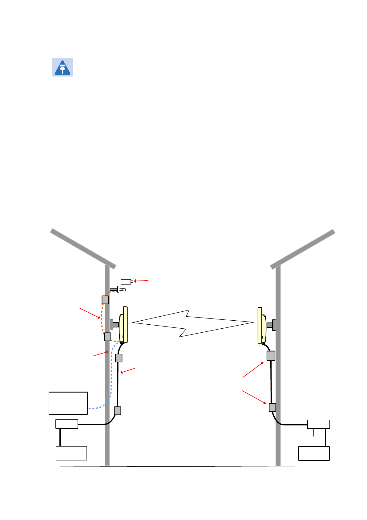
Chapter 1: Product description Overview of the PTP 670 Series
Note
Building
1
ODU
AC supply
PSU
Out-of-band
local
managem ent
Auxiliary
equipment
Netwo rk
equipment
Building 2
ODU
PSU
Netwo rk
equipment
AC supply
Power over Ethernet
inter face
Optical or copper SFP
Ethernet interface to
connected device
(not powered)
Ethernet interface
(with opt ional
power) to auxiliary
de vi ce
Lightning
protection units
The supported frequency coverage may be further restricted in some country licenses to
comply with the applicable regulations.
Typical bridge deployment
The PTP 670 is an “all outdoor” solution consisting of a wireless bridge between two sites.
Each site installation consists of a PTP 670 Integrated or PTP 670 Connectorized outdoor unit
(ODU), and a power injector (PSU) (Figure 1). The ODU provides the following interfaces:
• PSU port: This provides proprietary power over Ethernet and connection to the
management and/or data networks via 100BASE-TX or 1000BASE-T Ethernet. In the basic
configuration, this is the only Ethernet connection to the ODU.
• SFP port: This provides an optical or copper Gigabit Ethernet interface for customer data
and/or network management.
• Aux port: This provides an optional power and 100BASE-TX or 1000BASE-T Ethernet
connection to an IEEE803.2at device such as a video camera or wireless access point.
Figure 1 PTP 670 typical bridge deployment
Page 1-4

Chapter 1: Product description Overview of the PTP 670 Series
Hardware overview
The main hardware components of the PTP 670 are as follows:
• Outdoor unit (ODU): The ODU is a self-contained transceiver unit that houses both radio
and networking electronics. The PTP 670 ODU is supplied in two configurations:
o A PTP 670 Integrated ODU attached to a 23 dBi flat plate antenna
o A PTP 670 Connectorized ODU intended to work with separately mounted external
antennas.
• The ODU is supplied in the following frequency variants:
o 4.8 to 5.9 GHz
o 4.9 to 6.05 GHz
• The ODU is supplied in the following regional variants:
o FCC, intended for deployment in the USA
o European Union (EU), intended for deployment in countries of the European Union or
other countries following ETSI regulations
o IC, intended for deployment in Canada under the rules of ISEDC.
o Mexico, intended for use in Mexico
o RoW, intended for deployment in countries other than USA, Canada and EU countries.
• Power supply unit (PSU): PTP 670 provides three options for PSUs:
o The AC Power Injector 56V is suitable for powering a single ODU without an auxiliary
device. The AC Power Injector 56V is not approved for use with the 4.8 GHz to 5.9 GHz
frequency variants of PTP 670.
o The AC+DC Power Injector 56V is required when powering a single PTP 670 ODU from
a DC supply, when powering an auxiliary device, when using PTP-SYNC, or when the
PSU is needed to operate at extreme temperatures.
o The Cluster Management Module (CMM5) is a modular system consisting of power
injectors, power supplies, a controller and a GPS receiver. Each Power and Sync
Injector can power up to four ODUs. CMM5 also distributes a synchronization signal
from a Universal GPS (UGPS) receiver to the ODUs.
• Antennas and antenna cabling: Connectorized ODUs require external antennas connected
using RF cable.
• PTP SYNC unit (optional): The PTP SYNC unit can be used with the AC+DC Enhanced
Power Injector 56V to provide TDD synchronization at a TDD Master ODU. PTP-SYNC must
be used with the AC+DC Enhanced Power Injector 56V.
• GPS receivers: PTP 670 supports two different GPS receivers for network-wide TDD
synchronization. The Trimble Acutime™GG GPS receiver is used with PTP-SYNC. The
Universal GPS (UGPS) receiver is used with CMM5.
• Network Indoor Unit (NIDU) (optional): The NIDU allows up to eight TDM channels (E1 or
T1) to be bridged over a PTP 670 link.
• Ethernet cabling: All configurations require a copper Ethernet Cat5e connection from the
ODU (PSU port) to the PSU. Advanced configurations may also require one or both of the
following:
o A copper or optical Ethernet connection from the ODU (SFP port) to network
terminating equipment or another device.
Page 1-5

Chapter 1: Product description Overview of the PTP 670 Series
o A copper Ethernet Cat5e connection from the ODU (Aux port) to an auxiliary device.
• Lightning protection unit (LPU): LPUs are installed in the PSU and Aux copper drop cables
to provide transient voltage surge suppression.
• Ground cables: ODU, LPUs and outdoor copper Ethernet cables are bonded to the site
grounding system using ground cables.
For more information about these components, including interfaces, specifications and
Cambium part numbers, refer to Chapter 2: System hardware.
Page 1-6
 Loading...