

Cambium Networks 50650 User Manual

Cambium
PTP 650 Series
User Guide
System Release 650-01-00

Accuracy
Copyrights
Restrictions
License Agreements
High Risk Materials
While reasonable efforts have been made to assure the accuracy of this document, Cambium Networks
assumes no liability resulting from any inaccuracies or omissions in this document, or from use of the
information obtained herein. Cambium reserves the right to make changes to any products described
herein to improve reliability, function, or design, and reserves the right to revise this document and to
make changes from time to time in content hereof with no obligation to notify any person of revisions
or changes. Cambium does not assume any liability arising out of the application or use of any
product, software, or circuit described herein; neither does it convey license under its patent rights or
the rights of others. It is possible that this publication may contain references to, or information about
Cambium products (machines and programs), programming, or services that are not announced in
your country. Such references or information must not be construed to mean that Cambium intends to
announce such Cambium products, programming, or services in your country.
This document, Cambium products, and 3rd Party software products described in this document may
include or describe copyrighted Cambium and other 3
rd
Party supplied computer programs stored in
semiconductor memories or other media. Laws in the United States and other countries preserve for
rd
Cambium, its licensors, and other 3
Party supplied software certain exclusive rights for copyrighted
material, including the exclusive right to copy, reproduce in any form, distribute and make derivative
works of the copyrighted material. Accordingly, any copyrighted material of Cambium, its licensors, or
rd
Party software supplied material contained in the Cambium products described in this
the 3
document may not be copied, reproduced, reverse engineered, distributed, merged or modified in any
manner without the express written permission of Cambium. Furthermore, the purchase of Cambium
products shall not be deemed to grant either directly or by implication, estoppel, or otherwise, any
license under the copyrights, patents or patent applications of Cambium or other 3rd Party supplied
software, except for the normal non-exclusive, royalty free license to use that arises by operation of
law in the sale of a product.
Software and documentation are copyrighted materials. Making unauthorized copies is prohibited by
law. No part of the software or documentation may be reproduced, transmitted, transcribed, stored in a
retrieval system, or translated into any language or computer language, in any form or by any means,
without prior written permission of Cambium.
The software described in this document is the property of Cambium and its licensors. It is furnished
by express license agreement only and may be used only in accordance with the terms of such an
agreement.
Cambium and its supplier(s) specifically disclaim any express or implied warranty of fitness for any
high risk activities or uses of its products including, but not limited to, the operation of nuclear
facilities, aircraft navigation or aircraft communication systems, air traffic control, life support, or
weapons systems (“High Risk Use”). Any High Risk is unauthorized, is made at your own risk and you
shall be responsible for any and all losses, damage or claims arising out of any High Risk Use.
© 2013 Cambium Networks Limited. All Rights Reserved.
phn-3341_002v002 (Aug 2013)

About This User Guide .......................................................................................................................... 1
Chapter 1: Product description ....................................................................................................... 1-1
Contents
Contacting Cambium Networks .................................................................................................... 1
Purpose ........................................................................................................................................... 2
Cross references ............................................................................................................................. 2
Feedback ......................................................................................................................................... 2
Important regulatory information........................................................................................................ 3
Radar avoidance ............................................................................................................................. 3
USA and Canada specific information ......................................................................................... 3
Specific expertise and training required for professional installers ......................................... 4
Avoidance of weather radars ........................................................................................................ 4
External antennas ........................................................................................................................... 4
Ethernet networking skills ............................................................................................................. 4
Lightning protection ....................................................................................................................... 5
Training ........................................................................................................................................... 5
Problems and warranty ........................................................................................................................ 6
Reporting problems ....................................................................................................................... 6
Repair and service .......................................................................................................................... 6
Hardware warranty ........................................................................................................................ 6
Security advice ...................................................................................................................................... 7
Warnings, cautions, and notes ............................................................................................................ 8
Warnings ......................................................................................................................................... 8
Cautions .......................................................................................................................................... 8
Notes ............................................................................................................................................... 8
Caring for the environment .................................................................................................................. 9
In EU countries ............................................................................................................................... 9
In non-EU countries ....................................................................................................................... 9
Overview of the PTP 650 ................................................................................................................... 1-2
Purpose ........................................................................................................................................ 1-2
Key features ................................................................................................................................. 1-2
Frequency bands ......................................................................................................................... 1-3
i
Page

Contents
Typical bridge deployment ........................................................................................................ 1-4
Hardware overview ..................................................................................................................... 1-5
Wireless operation ............................................................................................................................. 1-6
Time division duplexing ............................................................................................................. 1-6
Link mode optimization .............................................................................................................. 1-8
Link symmetry ............................................................................................................................. 1-8
OFDM and channel bandwidth .................................................................................................. 1-9
Spectrum management .............................................................................................................. 1-9
Adaptive modulation ................................................................................................................ 1-10
MIMO .......................................................................................................................................... 1-11
Dynamic spectrum optimization .............................................................................................. 1-12
Radar avoidance ........................................................................................................................ 1-12
Encryption .................................................................................................................................. 1-13
License keys and regulatory bands ......................................................................................... 1-13
PTP networks ............................................................................................................................. 1-14
Ethernet bridging ............................................................................................................................. 1-15
Ethernet ports ............................................................................................................................ 1-15
Customer data network ............................................................................................................ 1-16
Network management .............................................................................................................. 1-18
Ethernet loopback mode........................................................................................................... 1-21
Protocol model .......................................................................................................................... 1-21
System management ....................................................................................................................... 1-23
Management agent ................................................................................................................... 1-23
IPv6 ............................................................................................................................................. 1-24
Web server ................................................................................................................................. 1-25
RADIUS authentication ............................................................................................................. 1-27
SNMP.......................................................................................................................................... 1-28
Simple Network Time Protocol (SNTP) ................................................................................... 1-28
SNMPv3 security ....................................................................................................................... 1-29
System logging (syslog) ........................................................................................................... 1-32
AES license ................................................................................................................................ 1-32
Critical security parameters ..................................................................................................... 1-33
Login information ...................................................................................................................... 1-33
Capability upgrades .................................................................................................................. 1-33
Full capability trial period ......................................................................................................... 1-34
Software upgrade ...................................................................................................................... 1-34
ii
Page

Contents
Chapter 2: System hardware .......................................................................................................... 2-1
Chapter 3: System planning ........................................................................................................... 3-1
Recovery mode .......................................................................................................................... 1-35
Outdoor unit (ODU) ........................................................................................................................... 2-2
ODU description .......................................................................................................................... 2-2
ODU part numbers ...................................................................................................................... 2-3
ODU mounting brackets ............................................................................................................. 2-5
ODU interfaces ............................................................................................................................ 2-6
ODU specifications ...................................................................................................................... 2-7
Power supply units (PSU) .................................................................................................................. 2-8
PSU description ........................................................................................................................... 2-8
PSU part numbers ....................................................................................................................... 2-9
AC Power Injector interfaces ...................................................................................................... 2-9
AC+DC Enhanced Power Injector interfaces ........................................................................... 2-10
PSU specifications ..................................................................................................................... 2-11
Antennas and antenna cabling ....................................................................................................... 2-13
Antenna requirements .............................................................................................................. 2-13
RF cable and connectors........................................................................................................... 2-13
Antenna accessories ................................................................................................................. 2-14
FCC and IC approved antennas ................................................................................................ 2-14
Ethernet cabling ............................................................................................................................... 2-20
Ethernet standards and cable lengths ..................................................................................... 2-20
Outdoor copper Cat5e Ethernet cable ..................................................................................... 2-21
Cable grounding kit ................................................................................................................... 2-22
Lightning protection unit (LPU) and grounding kit ................................................................ 2-23
RJ45 connectors and spare glands .......................................................................................... 2-24
Cable hoisting grip .................................................................................................................... 2-25
Drop cable tester ....................................................................................................................... 2-26
Indoor Cat5e cable .................................................................................................................... 2-26
SFP module kits ......................................................................................................................... 2-27
Optical cable and connectors ................................................................................................... 2-29
Typical deployment ........................................................................................................................... 3-2
ODU with POE interface to PSU ................................................................................................. 3-2
SFP and Aux Ethernet interfaces ............................................................................................... 3-5
Site planning....................................................................................................................................... 3-8
Grounding and lightning protection .......................................................................................... 3-8
iii
Page

Contents
Lightning protection zones ......................................................................................................... 3-8
Site grounding system.............................................................................................................. 3-10
ODU and external antenna location ........................................................................................ 3-10
ODU wind loading ..................................................................................................................... 3-11
PSU DC power supply............................................................................................................... 3-12
PSU location .............................................................................................................................. 3-12
Drop cable grounding points ................................................................................................... 3-13
LPU location ............................................................................................................................... 3-13
Multiple LPUs ............................................................................................................................ 3-14
Radio spectrum planning ................................................................................................................ 3-16
General wireless specifications ............................................................................................... 3-16
Regulatory limits ....................................................................................................................... 3-17
Conforming to the limits........................................................................................................... 3-17
Available spectrum ................................................................................................................... 3-18
Channel bandwidth ................................................................................................................... 3-18
Frequency selection .................................................................................................................. 3-19
Avoidance of weather radars (USA only) ............................................................................... 3-20
Link planning .................................................................................................................................... 3-21
PTP LINKPlanner ....................................................................................................................... 3-21
Range and obstacles ................................................................................................................. 3-21
Path loss ..................................................................................................................................... 3-22
Adaptive modulation ................................................................................................................ 3-22
Calculating data rate capacity .................................................................................................. 3-23
Planning for connectorized units .................................................................................................... 3-25
When to install connectorized units ........................................................................................ 3-25
Choosing external antennas .................................................................................................... 3-25
Calculating RF cable length (5.8 GHz FCC only) ..................................................................... 3-26
Data network planning .................................................................................................................... 3-27
Ethernet interfaces .................................................................................................................... 3-27
Layer 2 control protocols .......................................................................................................... 3-27
Ethernet port allocation ............................................................................................................ 3-28
VLAN membership .................................................................................................................... 3-28
Priority for management traffic ............................................................................................... 3-28
IP interface ................................................................................................................................. 3-29
Quality of service for bridged Ethernet traffic ........................................................................ 3-29
“Daisy-chaining” PTP 650 links ............................................................................................... 3-30
iv
Page

Contents
Chapter 4: Legal and regulatory information ................................................................................ 4-1
Green Ethernet switches........................................................................................................... 3-30
Network management planning ..................................................................................................... 3-31
Planning for SNMP operation .................................................................................................. 3-31
Supported diagnostic alarms ................................................................................................... 3-32
Enabling SNMP ......................................................................................................................... 3-32
Security planning ............................................................................................................................. 3-33
Planning for SNTP operation ................................................................................................... 3-33
Planning for HTTPS/TLS operation .......................................................................................... 3-33
Planning for SNMPv3 operation .............................................................................................. 3-35
Planning for RADIUS operation ............................................................................................... 3-39
System threshold, output power and link loss .............................................................................. 3-41
Data throughput capacity tables ..................................................................................................... 3-47
Cambium Networks end user license agreement ........................................................................... 4-2
Acceptance of this agreement ................................................................................................... 4-2
Definitions .................................................................................................................................... 4-2
Grant of license ........................................................................................................................... 4-2
Conditions of use ........................................................................................................................ 4-3
Title and restrictions ................................................................................................................... 4-4
Confidentiality ............................................................................................................................. 4-4
Right to use Cambium’s name ................................................................................................... 4-5
Transfer ........................................................................................................................................ 4-5
Updates ........................................................................................................................................ 4-5
Maintenance ................................................................................................................................ 4-5
Disclaimer .................................................................................................................................... 4-6
Limitation of liability ................................................................................................................... 4-6
U.S. government ......................................................................................................................... 4-6
Term of license ............................................................................................................................ 4-7
Governing law ............................................................................................................................. 4-7
Assignment .................................................................................................................................. 4-7
Survival of provisions ................................................................................................................. 4-7
Entire agreement ......................................................................................................................... 4-7
Third party software .................................................................................................................... 4-7
Compliance with safety standards ................................................................................................. 4-23
Electrical safety compliance ..................................................................................................... 4-23
Electromagnetic compatibility (EMC) compliance ................................................................. 4-23
v
Page

Contents
Chapter 5: Installation .................................................................................................................... 5-1
Human exposure to radio frequency energy .......................................................................... 4-24
Compliance with radio regulations ................................................................................................ 4-27
Type approvals .......................................................................................................................... 4-27
FCC/IC compliance .................................................................................................................... 4-29
European Union compliance .................................................................................................... 4-33
Safety .................................................................................................................................................. 5-2
Power lines .................................................................................................................................. 5-2
Working at heights ...................................................................................................................... 5-2
PSU ............................................................................................................................................... 5-2
Grounding and protective earth ................................................................................................ 5-2
DC supply ..................................................................................................................................... 5-3
Powering down before servicing ............................................................................................... 5-3
Primary disconnect device ......................................................................................................... 5-3
External cables ............................................................................................................................ 5-3
Drop cable tester ......................................................................................................................... 5-3
RF exposure near the antenna ................................................................................................... 5-3
Minimum separation distances ................................................................................................. 5-4
Grounding and lightning protection requirements .................................................................. 5-4
Grounding cable installation methods ...................................................................................... 5-4
Siting ODUs and antennas ......................................................................................................... 5-4
Installing the ODU and top LPU ........................................................................................................ 5-5
Decide how to mount the ODU and top LPU ............................................................................ 5-5
Prepare ODU for mounting ........................................................................................................ 5-6
Integrated ODU ............................................................................................................................ 5-7
Connectorized ODU ..................................................................................................................... 5-9
Ground the ODU and top LPU ................................................................................................. 5-10
Install external antennas for a connectorized ODU ............................................................... 5-11
Installing the copper Cat5e Ethernet interface .............................................................................. 5-13
Install the ODU to top LPU drop cable .................................................................................... 5-13
Install the main drop cable ....................................................................................................... 5-15
Install the bottom LPU to PSU drop cable .............................................................................. 5-18
Test resistance in the drop cable ............................................................................................. 5-20
Installing the PSU ............................................................................................................................. 5-21
Installing the AC Power Injector .............................................................................................. 5-21
Installing the AC+DC Enhanced Power Injector ..................................................................... 5-22
vi
Page

Contents
Chapter 6: Configuration and alignment ....................................................................................... 6-1
Installing an SFP Ethernet interface ............................................................................................... 5-23
Fitting the long cable gland ...................................................................................................... 5-25
Inserting the SFP module ......................................................................................................... 5-26
Connecting the cable ................................................................................................................ 5-29
Fitting the gland ........................................................................................................................ 5-30
Removing the cable and SFP module ..................................................................................... 5-31
Installing an Aux Ethernet interface ............................................................................................... 5-32
Supplemental installation information .......................................................................................... 5-33
Stripping drop cable ................................................................................................................. 5-33
Creating a drop cable grounding point ................................................................................... 5-34
Weatherproofing an N type connector .................................................................................... 5-37
Replacing PSU fuses ................................................................................................................. 5-40
Preparing for configuration and alignment ..................................................................................... 6-2
Safety precautions ...................................................................................................................... 6-2
Regulatory compliance ............................................................................................................... 6-2
Selecting configuration options ................................................................................................. 6-2
Generating a License Key ........................................................................................................... 6-3
Connecting to the unit ....................................................................................................................... 6-5
Configuring the management PC .............................................................................................. 6-5
Connecting to the PC and powering up .................................................................................... 6-6
Using the web interface ..................................................................................................................... 6-7
Logging into the web interface .................................................................................................. 6-7
Using the menu options ............................................................................................................. 6-8
Installation menu ............................................................................................................................. 6-10
Starting the Installation Wizard ............................................................................................... 6-10
Disarm Installation page ........................................................................................................... 6-11
Current Installation Summary page ........................................................................................ 6-11
Software License Key page ...................................................................................................... 6-12
Interface Configuration page ................................................................................................... 6-14
Wireless Configuration page .................................................................................................... 6-15
Confirm Installation Configuration page ................................................................................. 6-20
System menu.................................................................................................................................... 6-21
System Configuration page ..................................................................................................... 6-21
LAN Configuration page ........................................................................................................... 6-24
QoS Configuration page ........................................................................................................... 6-30
vii
Page

Contents
SFP Configuration page ............................................................................................................ 6-33
Save & Restore Configuration page ........................................................................................ 6-34
Software Upgrade page............................................................................................................ 6-37
Management menu .......................................................................................................................... 6-39
Web-Based Management page ................................................................................................ 6-39
Local User Accounts page ........................................................................................................ 6-42
RADIUS Configuration page .................................................................................................... 6-47
Webpage Properties page ........................................................................................................ 6-49
Email Configuration page ......................................................................................................... 6-52
Diagnostic Alarms page............................................................................................................ 6-54
Time Configuration page .......................................................................................................... 6-55
Syslog Configuration page ....................................................................................................... 6-59
SNMP pages (for SNMPv3) ............................................................................................................. 6-61
Current SNMP Summary (for SNMPv3) .................................................................................. 6-61
Step 1: SNMP Configuration (for SNMPv3) ............................................................................ 6-62
Step 2: SNMP MIB-II System Objects (for SNMPv3) .............................................................. 6-64
Step 3: SNMP User Policy Configuration (for SNMPv3) ........................................................ 6-65
Step 4: SNMP User Accounts Configuration (for SNMPv3) .................................................. 6-67
Step 5: SNMP Trap Configuration (for SNMPv3) ................................................................... 6-69
Confirm SNMP Configuration (for SNMPv3) .......................................................................... 6-70
SNMP pages (for SNMPv1/2c) ........................................................................................................ 6-71
Current SNMP Summary (for SNMPv1/2c) ............................................................................. 6-71
Step 1: SNMP Configuration (for SNMPv1/2c) ....................................................................... 6-71
Step 2: SNMP MIB-II System Objects (for SNMPv1/2c) ......................................................... 6-72
Step 3: SNMP Trap Configuration (for SNMPv1/2c) .............................................................. 6-73
Confirm SNMP Configuration (for SNMPv1/2c) ..................................................................... 6-74
Security menu .................................................................................................................................. 6-75
Preparing for HTTPS/TLS.......................................................................................................... 6-75
Security Configuration Wizard page ....................................................................................... 6-76
Step 1: Enter Key of Keys ......................................................................................................... 6-77
Step 2: Enter TLS Private Key and Public Certificate ............................................................. 6-78
Step 3: Enter User Security Banner ......................................................................................... 6-79
Step 4: Enter Login Information Settings................................................................................ 6-80
Step 5: Enter Random Number Entropy Input ....................................................................... 6-81
Step 6: Enter Wireless Link Encryption Key ............................................................................ 6-82
Step 7: Enter HTTP and Telnet Settings .................................................................................. 6-83
viii
Page

Contents
Chapter 7: Operation ...................................................................................................................... 7-1
Step 8: Commit Security Configuration .................................................................................. 6-85
Zeroize CSPs page ..................................................................................................................... 6-86
Aligning antennas ............................................................................................................................ 6-87
Starting up the units ................................................................................................................. 6-87
Checking that the units are armed ........................................................................................... 6-87
Aligning antennas ..................................................................................................................... 6-88
Aligning separate antennas for spatial diversity .................................................................... 6-89
ODU installation tones .............................................................................................................. 6-90
Graphical Install page ............................................................................................................... 6-92
Disarming the units ................................................................................................................... 6-93
Comparing actual to predicted performance ......................................................................... 6-94
Other configuration tasks ................................................................................................................ 6-95
Connecting to the network ....................................................................................................... 6-95
Upgrading software using TFTP .............................................................................................. 6-96
System summary and status ............................................................................................................ 7-2
System Summary page .............................................................................................................. 7-2
System Status page .................................................................................................................... 7-3
Rebooting and logging out ............................................................................................................... 7-9
Login Information page .............................................................................................................. 7-9
Reboot Wireless Unit page ......................................................................................................... 7-9
Change Password page ............................................................................................................ 7-10
Logging out ................................................................................................................................ 7-11
Alarms, alerts and messages .......................................................................................................... 7-12
Alarms ........................................................................................................................................ 7-12
Email alerts ................................................................................................................................ 7-15
Syslog page ............................................................................................................................... 7-16
Format of syslog server messages .......................................................................................... 7-17
Configuration and status messages ........................................................................................ 7-17
Event messages ......................................................................................................................... 7-18
Spectrum management ................................................................................................................... 7-20
Spectrum Management page .................................................................................................. 7-20
Interpreting the spectrum management plots ....................................................................... 7-23
Viewing the active channel history .......................................................................................... 7-29
Viewing historic spectrum management metrics .................................................................. 7-30
Barring channels ....................................................................................................................... 7-31
ix
Page

Contents
Chapter 8: Troubleshooting ........................................................................................................... 8-1
Glossary .................................................................................................................................................. I
System statistics .............................................................................................................................. 7-32
System Statistics page.............................................................................................................. 7-32
Wireless Port Counters page .................................................................................................... 7-37
Main Port Counters page .......................................................................................................... 7-38
Aux Port Counters page............................................................................................................ 7-40
SFP Port Counters page ............................................................................................................ 7-41
Diagnostics Plotter page ........................................................................................................... 7-42
Generate Downloadable Diagnostics page............................................................................. 7-43
Recovery mode ................................................................................................................................ 7-44
Entering recovery mode ........................................................................................................... 7-44
Upgrading software image....................................................................................................... 7-46
Resetting IP & Ethernet configuration ..................................................................................... 7-47
Erasing configuration ................................................................................................................ 7-48
Zeroize Critical Security Parameters page .............................................................................. 7-50
Rebooting the unit ..................................................................................................................... 7-51
Testing link end hardware ................................................................................................................. 8-2
AC Power Injector LED sequence .............................................................................................. 8-2
AC+DC Enhanced power injector LED sequence ..................................................................... 8-2
Ethernet packet test ..................................................................................................................... 8-6
Testing the radio link ......................................................................................................................... 8-9
No activity .................................................................................................................................... 8-9
Some activity ............................................................................................................................... 8-9
Radio and television interference ............................................................................................ 8-10
Page
x

About This User Guide
This guide describes the planning, installation, configuration and operation of the Cambium
PTP 650 Series of point-to-point wireless Ethernet bridges. It is intended for use by the system
designer, system installer and system administrator.
For radio network design, refer to the following chapters:
• Chapter 1: Product description
• Chapter 2: System hardware
• Chapter 3: System planning
• Chapter 4: Legal and regulatory information
For radio equipment installation, refer to the following chapter:
• Chapter 5: Installation
For system configuration, monitoring and fault-finding, refer to the following chapters:
• Chapter 6: Configuration and alignment
• Chapter 7: Operation
• Chapter 8: Troubleshooting
Contacting Cambium Networks
Support website: http://www.cambiumnetworks.com/support
Main website: http://www.cambiumnetworks.com
Sales enquiries: solutions@cambiumnetworks.com
Support enquiries: support@cambiumnetworks.com
Telephone number list: http://www.cambiumnetworks.com/contact
Address: Cambium Networks Limited,
Linhay Business Park,
Eastern Road,
Ashburton,
Devon, UK,
TQ13 7UP
Page
1

About This User Guide Important regulatory information
Purpose
Cambium Networks Point-To-Point (PTP) documents are intended to instruct and assist personnel
in the operation, installation and maintenance of the Cambium PTP equipment and ancillary
devices. It is recommended that all personnel engaged in such activities be properly trained.
Cambium disclaims all liability whatsoever, implied or express, for any risk of damage, loss or
reduction in system performance arising directly or indirectly out of the failure of the customer, or
anyone acting on the customer's behalf, to abide by the instructions, system parameters, or
recommendations made in this document.
Cross references
References to external publications are shown in italics. Other cross references, emphasized in
blue text in electronic versions, are active links to the references.
This document is divided into numbered chapters that are divided into sections. Sections are not
numbered, but are individually named at the top of each page, and are listed in the table of
contents.
Feedback
We appreciate feedback from the users of our documents. This includes feedback on the structure,
content, accuracy, or completeness of our documents. Send feedback to
support@cambiumnetworks.com
.
Page
2

About This User Guide Important regulatory information
Note
Important regulatory information
The PTP 650 product is certified as an unlicensed device in frequency bands where it is not allowed
to cause interference to licensed services (called primary users of the bands).
Radar avoidance
In countries where radar systems are the primary band users, the regulators have mandated
special requirements to protect these systems from interference caused by unlicensed devices.
Unlicensed devices must detect and avoid co-channel operation with radar systems.
The PTP 650 provides detect and avoid functionality for countries and frequency bands requiring
protection for radar systems.
Installers and users must meet all local regulatory requirements for radar detection. To
meet these requirements, users must install a license key for the correct country during
commissioning of the PTP 650. If this is not done, installers and users may be liable to civil
and criminal penalties.
Contact the Cambium helpdesk if more guidance is required.
USA and Canada specific information
The USA Federal Communications Commission (FCC) has asked manufacturers to implement
special features to prevent interference to weather radar systems that operate in the band 5600
MHz to 5650 MHz. These features must be implemented in all products able to operate outdoors in
the band 5470 MHz to 5725 MHz.
Manufacturers must ensure that such radio products cannot be configured to operate outside of
FCC rules; specifically it must not be possible to disable or modify the radar protection functions
that have been demonstrated to the FCC.
In order to comply with these FCC requirements, Cambium supplies variants of the PTP 650 for
operation in the USA or Canada. These variants are only allowed to operate with license keys that
comply with FCC/IC rules. In particular, operation of radio channels overlapping the band
5600-5650 MHz is not allowed and these channels are permanently barred.
In addition, other channels may also need to be barred when operating close to weather radar
installations.
To ensure compliance with FCC rules (KDB 443999: Interim Plans to Approve UNII
Devices Operating in the 5470 - 5725 MHz Band with Radar Detection and DFS
Capabilities), follow Avoidance of weather radars (USA only) on page 3-20.
Page
3

About This User Guide Important regulatory information
Other variants of the PTP 650 are available for use in the rest of the world, but these variants are
not supplied to the USA or Canada except under strict controls, when they are needed for export
and deployment outside the USA or Canada.
Specific expertise and training required for professional installers
To ensure that the PTP 650 is installed and configured in compliance with the requirements of
Industry Canada and the FCC, installers must have the radio engineering skills and training
described in this section. This is particularly important when installing and configuring a PTP 650
system for operation in the 5.4 GHz UNII band.
Avoidance of weather radars
The installer must be familiar with the requirements in FCC KDB 443999. Essentially, the installer
must be able to:
• Access the FCC data base of weather radar location and channel frequencies.
• Use this information to correctly configure the product (using the GUI) to avoid operation on
channels that should be barred according to the guidelines that are contained in the KDB and
explained in detail in this user guide.
External antennas
When using a connectorized version of the product (as compared to the version with an integrated
antenna), the conducted transmit power may need to be reduced to ensure the regulatory limit on
transmitter EIRP is not exceeded. The installer must have an understanding of how to compute
the effective antenna gain from the actual antenna gain and the feeder cable losses.
The range of permissible values for maximum antenna gain and feeder cable losses are included
in this user guide together with a sample calculation. The product GUI automatically applies the
correct conducted power limit to ensure that it is not possible for the installation to exceed the
EIRP limit, when the appropriate values for antenna gain and feeder cable losses are entered into
the GUI.
Ethernet networking skills
The installer must have the ability to configure IP addressing on a PC and to set up and control
products using a web browser interface.
4
Page

About This User Guide Important regulatory information
Lightning protection
To protect outdoor radio installations from the impact of lightning strikes, the installer must be
familiar with the normal procedures for site selection, bonding and grounding. Installation
guidelines for the PTP 650 can be found in Chapter 2: System hardware and Chapter 5: Installation.
Training
The installer needs to have basic competence in radio and IP network installation. The specific
requirements applicable to the PTP 650 should be gained by reading Chapter 5: Installation and
Chapter 6: Configuration and alignment and by performing sample set ups at base workshop
before live deployments.
Page
5

About This User Guide Problems and warranty
1
2
3
4
5
Caution
Problems and warranty
Reporting problems
If any problems are encountered when installing or operating this equipment, follow this
procedure to investigate and report:
Search this document and the software release notes of supported releases.
Visit the support website.
Ask for assistance from the Cambium product supplier.
Gather information from affected units, such as any available diagnostic downloads.
Escalate the problem by emailing or telephoning support.
Repair and service
If unit failure is suspected, obtain details of the Return Material Authorization (RMA) process from
the support website.
Hardware warranty
Cambium’s standard hardware warranty is for one (1) year from date of shipment from Cambium
Networks or a Cambium distributor. Cambium Networks warrants that hardware will conform to
the relevant published specifications and will be free from material defects in material and
workmanship under normal use and service. Cambium shall within this time, at its own option,
either repair or replace the defective product within thirty (30) days of receipt of the defective
product. Repaired or replaced product will be subject to the original warranty period but not less
than thirty (30) days.
To register PTP products or activate warranties, visit the support website. For warranty assistance,
contact the reseller or distributor.
Using non-Cambium parts for repair could damage the equipment or void warranty.
Contact Cambium for service and repair instructions.
Portions of Cambium equipment may be damaged from exposure to electrostatic
discharge. Use precautions to prevent damage.
6
Page

About This User Guide Security advice
Security advice
Cambium Networks systems and equipment provide security parameters that can be configured
by the operator based on their particular operating environment. Cambium recommends setting
and using these parameters following industry recognized security practices. Security aspects to
be considered are protecting the confidentiality, integrity, and availability of information and
assets. Assets include the ability to communicate, information about the nature of the
communications, and information about the parties involved.
In certain instances Cambium makes specific recommendations regarding security practices,
however the implementation of these recommendations and final responsibility for the security of
the system lies with the operator of the system.
Page
7

About This User Guide Warnings, cautions, and notes
Warning
Caution
Note
Warnings, cautions, and notes
The following describes how warnings and cautions are used in this document and in all
documents of the Cambium Networks document set.
Warnings
Warnings precede instructions that contain potentially hazardous situations. Warnings are used to
alert the reader to possible hazards that could cause loss of life or physical injury. A warning has
the following format:
Warning text and consequence for not following the instructions in the warning.
Cautions
Cautions precede instructions and are used when there is a possibility of damage to systems,
software, or individual items of equipment within a system. However, this damage presents no
danger to personnel. A caution has the following format:
Caution text and consequence for not following the instructions in the caution.
Notes
A note means that there is a possibility of an undesirable situation or provides additional
information to help the reader understand a topic or concept. A note has the following format:
Note text.
Page
8

About This User Guide Caring for the environment
Caring for the environment
The following information describes national or regional requirements for the disposal of
Cambium Networks supplied equipment and for the approved disposal of surplus packaging.
In EU countries
The following information is provided to enable regulatory compliance with the European Union
(EU) directives identified and any amendments made to these directives when using Cambium
equipment in EU countries.
Disposal of Cambium equipment
European Union (EU) Directive 2002/96/EC Waste Electrical and Electronic Equipment (WEEE)
Do not dispose of Cambium equipment in landfill sites. For disposal instructions, refer to
http://www.cambiumnetworks.com/support
Disposal of surplus packaging
Do not dispose of surplus packaging in landfill sites. In the EU, it is the individual recipient’s
responsibility to ensure that packaging materials are collected and recycled according to the
requirements of EU environmental law.
In non-EU countries
In non-EU countries, dispose of Cambium equipment and all surplus packaging in accordance with
national and regional regulations.
Page
9
Chapter 1: Product description
This chapter provides a high level description of the PTP 650 product. It describes in general terms
the function of the product, the main product variants and the main hardware components. The
following topics are described in this chapter:
• Overview of the PTP 650 on page 1-2 introduces the key features, typical uses, product variants
and components of the PTP 650.
• Wireless operation on page 1-6 describes how the PTP 650 wireless link is operated, including
modulation modes, power control and spectrum management.
• Ethernet bridging on page 1-15 describes how the PTP 650 controls Ethernet data, in both the
customer data and system management networks.
• System management on page 1-23 introduces the PTP 650 management system, including the
web interface, installation, configuration, security, alerts and upgrades.
Page
1-1

Chapter 1: Product description Overview of the PTP 650
Overview of the PTP 650
This section introduces the key features, typical uses, product variants and components of the
PTP 650.
Purpose
Cambium PTP 650 Series Bridge products are designed for Ethernet bridging over point-to-point
microwave links in unlicensed and lightly-licensed frequency bands between 4.9 GHz and 5.8 GHz.
Users must ensure that the PTP 650 Series complies with local operating regulations.
The PTP 650 Series acts as a transparent bridge between two segments of the operator’s network.
In this sense, it can be treated as a virtual wired connection between two points. The PTP 650
Series
it does not need to forward. The system is transparent to higher-level protocols such as VLANs
and Spanning Tree.
forwards 802.3 Ethernet frames destined for the other part of the network and filters frames
Key features
The PTP 650 is a high performance wireless bridge for Ethernet traffic with a maximum throughput
of 450 Mbps. It is capable of operating in line-of-sight (LOS), near-LOS and non-LOS propagation
condition. Its maximum LOS range is 200 km.
The PTP 650 operates in unlicensed and lightly-licensed frequency bands between 4.9 and 5.8 GHz.
It has a very high spectral efficiency of 10 bps/Hz and supports a channel bandwidth of up to
45 MHz. The integrated ODU has its own flat plate antenna. The connectorized ODU is designed for
use with an external antenna.
The wireless link is TDD based and supports both symmetric and asymmetric configurations.
From a network point-of-view, the PTP 650 wireless link is a transparent Layer 2 bridge. It supports
up to three Gigabit Ethernet ports. Two ports support twisted pair Gigabit Ethernet. One of them is
capable of providing power via standard 802.3at PoE to an external device such as a video
surveillance camera or a wireless access point. The third port accepts either a twisted pair or fibre
GE SFP module.
PTP 650 has extensive quality of service (QoS) classification capability and supports up to eight
levels of queues. Management of the unit may be via the same interface as the bridged traffic (inband management) or on a separate port (out-of-band local management).
Table 1 gives a summary of the main PTP 650 characteristics.
1-2
Page

Chapter 1: Product description Overview of the PTP 650
Table 1
Characteristic
Value
Topology PTP
Wireless link condition LOS, near LOS or non-LOS
Range Up to 200 km
Duplexing TDD (symmetric and asymmetric)
Connectivity Ethernet
Operating frequencies 4.9 to 5.8 GHz
Channel bandwidth 10, 20, 40 or 45 MHz
High spectral efficiency Up to 10 bps/Hz
Data rate Up to 450 Mbps (45 MHz channel BW)
Main characteristics of the PTP 650 Series
Frequency bands
The PTP 650 ODU can be configured by the user to operate in the following bands:
• 4900 to 4990 MHz
• 5470 to 5725 MHz
• 5725 to 5875 MHz
Page
1-3
Chapter 1: Product description Overview of the PTP 650
Figure 1
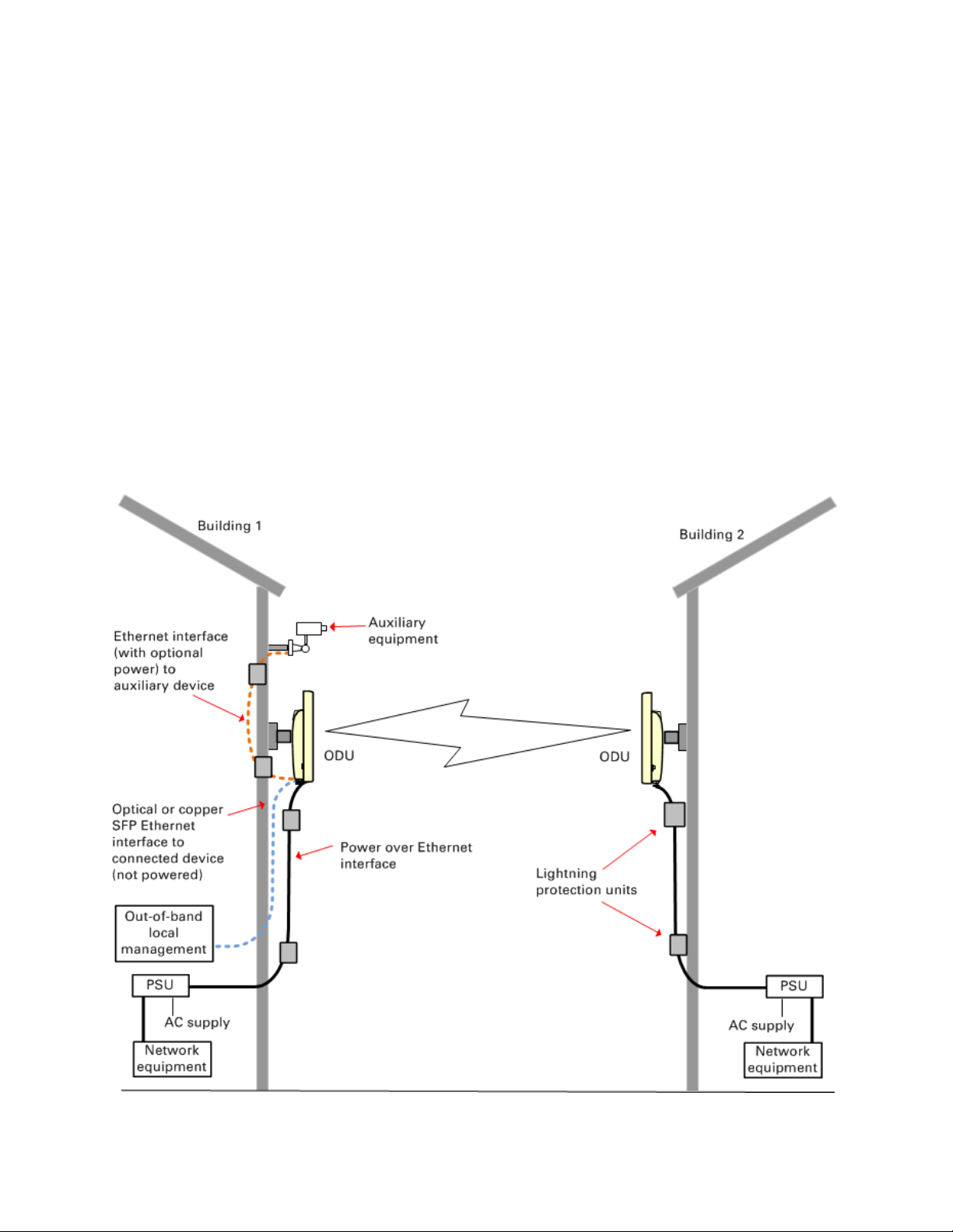
Typical bridge deployment
The PTP 650 is an “all outdoor” solution consisting of a wireless bridge between two sites. Each
site installation consists of an integrated or connectorized outdoor unit (ODU) and a power injector
(PSU) (Figure 1). The ODU provides the following interfaces:
• PSU port: This provides proprietary power over Ethernet and connection to the management
and/or data networks via 100BASE-TX or 1000BASE-T Ethernet. In the basic configuration, this
is the only Ethernet connection to the ODU.
• SFP port: This provides an optical or copper Gigabit Ethernet interface for out-of-band local
management, user data or user data with in-band management.
• Aux port: This provides an optional power and 100BASE-TX or 1000BASE-T Ethernet
connection to an IEEE803.2at device such as a video camera or wireless access point.
PTP 650 typical bridge deployment
Page
1-4

Chapter 1: Product description Overview of the PTP 650
Hardware overview
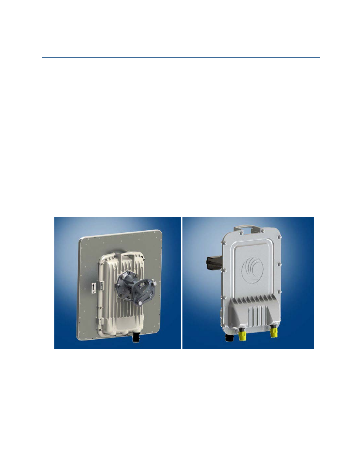
The main hardware components of the PTP 650 are as follows:
• Outdoor unit (ODU): The ODU is a self-contained transceiver unit that houses both radio and
networking electronics. The ODU is supplied in the following product variants:
o Integrated or Connectorized: The ODU may be either Integrated (attached to its own flat
plate antenna) or connectorized (without an antenna).
o FCC/IC, EU or RoW: These variants are for deployment in the USA and Canada, the EU and
the rest of the world respectively.
• Power supply unit (PSU): There is a choice of two PSUs:
o The AC Power Injector is suitable for installations without an auxiliary device.
o The AC+DC power injector is required when powering from a DC supply or when the PSU
is needed to operate at extreme temperatures.
• Antennas and antenna cabling: Connectorized ODUs require external antennas connected
using RF cable.
• Ethernet cabling: All configurations require a copper Ethernet Cat5e connection from the ODU
(PSU port) to the PSU. Advanced configurations may also require one or both of the following:
o A copper or optical Ethernet connection from the ODU (SFP port) to network terminating
equipment or another device.
o A copper Ethernet Cat5e connection from the ODU (Aux port) to an auxiliary device.
• Lightning protection unit (LPU): LPUs are installed in the PSU and Aux copper drop cables to
provide transient voltage surge suppression.
• Ground cables: ODU, LPUs and outdoor copper Ethernet cables are bonded to the site
grounding system using ground cables.
For more information about these components, including interfaces, specifications and Cambium
part numbers, refer to Chapter 2: System hardware.
1-5
Page

Chapter 1: Product description Wireless operation
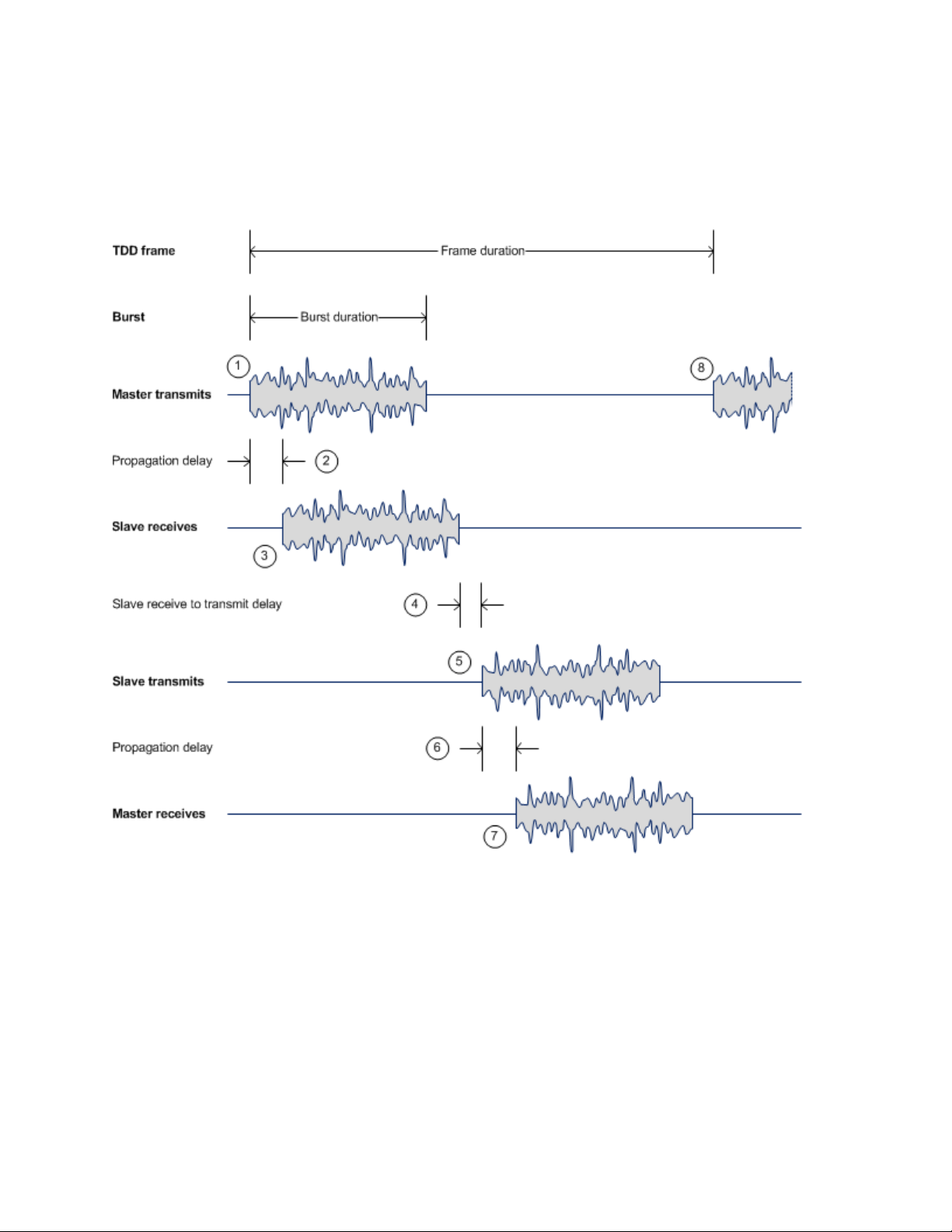
1
The TDD m
2
A delay occurs as the
3
The s
4
T
5
The slave transmits a burst to the
6
A delay occurs as the
7
The m
8
The m
Wireless operation
This section describes how the PTP 650 wireless link is operated, including modulation modes,
power control and security.
Time division duplexing
TDD cycle
PTP 650 links operate using Time Division Duplexing (TDD). They use a TDD cycle in which the
ODUs alternately transmit and receive TDD bursts. The TDD cycle is illustrated in Figure 2. The
steps in the cycle are as follows:
aster transmits a burst to the TDD slave.
master-slave burst propagates over the link.
lave receives the burst from the master.
he slave processes the master-slave burst.
master.
slave-master burst propagates over the link.
aster receives the burst from the slave.
aster transmits the next burst to the slave.
TDD frame parameters
The TDD burst duration varies depending on the following:
• Channel bandwidth
• Link range
• Link optimization mode
• Link symmetry
• Offered traffic loading.
The TDD frame duration varies depending on the following:
• TDD burst duration master-slave.
• TDD burst duration slave-master.
• Link range.
Page
1-6
Chapter 1: Product description Wireless operation
Figure 2
The propagation delay in Step 2 is necessarily equal to the propagation delay in Step 6, and is
determined solely by the link range. There may be added delays between rx and tx on the master
and slave to minimize interference, as set up by the link planner or installer.
TDD cycle
Channel selection
The PTP 650 series links are capable of transmitting and receiving on the same channel or on
different channels. In other words, the slave-master direction may use a different channel from the
master-slave direction. Independent selection of transmit and receive frequencies can be useful in
planned networks or for countering interference.
When links operate in radar avoidance regions, each unit monitors its transmit channel for the
presence of radar signals. Therefore, the transmit and receive channels are always identical.
1-7
Page

Chapter 1: Product description Wireless operation
Symmetric –
2:1 –
1:2 –
Adaptive –
Link mode optimization
Link mode optimization allows the PTP 650 link to be optimized according to the type of traffic that
will be bridged. The link supports two modes, IP Traffic and TDM Traffic.
IP traffic
IP Traffic mode is optimized to provide the maximum possible link capacity. IP Traffic mode is an
appropriate choice where applications in the bridged networks provide some measure of reliable
transmission, and where very low latency is not critical. IP mode supports both fixed and adaptive
link symmetry (see Link symmetry on page 1-8).
TDM traffic
TDM Traffic mode is optimized to provide the lowest possible latency. TDM Traffic mode
additionally implements a more conservative approach to adaptive modulation, leading to lower
error rates in fading channels at the expense of slightly lower link capacity. TDM Traffic mode is an
appropriate choice for delay intolerant data without reliable transmission (for example voice over
IP data).
Link symmetry
The PTP 650 series provides four configuration options for apportioning the available capacity
between the two link directions.
•
allocating an equal Burst Duration for the Master and the Slave.
•
The capacity in the direction Master to Slave is twice that of the direction Slave to Master.
The PTP 650 series achieves this by setting the Burst Duration of the Master to twice that of the
Slave.
•
The capacity in the direction Slave to Master is twice that of the direction Master to Slave.
The PTP 650 series achieves this by setting the Burst Duration of the Slave to twice that of the
Master.
•
direction is dependent on the offered level of network traffic in both link directions. If the level
of offered traffic in both directions is equally high or equally low, the PTP 650 will allocate
equal capacity to both directions. If however the offered level of traffic is greater in one
direction, it is allocated a greater proportion of the overall link capacity. The PTP 650 series
achieves this by increasing (or decreasing) the duration of the Transmit Burst in a given link
direction as the offered level of network traffic increases (or decreases) in this same direction.
This is done independently for the two directions.
The Master and Slave have equal capacity. The PTP 650 series achieves this by
This is only available on the Full variant. The capacity allocated to a given link
Page
1-8

Chapter 1: Product description Wireless operation
Note
Adaptive mode is not available in the following configurations:
• When link mode optimization is set to TDM Traffic (see Link mode optimization on page 1-8).
• In regions where radar avoidance is operational (see Radar avoidance on page 1-12).
• When the ODU is not a Full variant.
OFDM and channel bandwidth
The PTP 650 series transmits using Orthogonal Frequency Division Multiplexing (OFDM). This
wideband signal consists of many equally spaced sub-carriers. Although each sub carrier is
modulated at a low rate using conventional modulation schemes, the resultant data rate from the
sub-carriers is high. OFDM works exceptionally over a Non-Line-of-Sight (NLoS) channel.
The channel bandwidth of the OFDM signal is configurable to one of the following values: 10, 20,
40 and 45 MHz. Higher bandwidths provide greater link capacity at the expense of using more
spectrum. Systems configured for a narrower channel bandwidth provide better receiver
sensitivity and can also be an appropriate choice in deployments where the amount of free
spectrum is limited.
Each channel is offset in center frequency from its neighboring channel by 10 or 5 MHz.
The Channel Bandwidth must be configured to the same value at both ends of the link.
Not all channel bandwidths are available in all regulatory bands.
Spectrum management
The spectrum management feature of the PTP 650 Series monitors the available wireless spectrum
and directs both ends of the wireless link to operate on a channel with a minimum level of cochannel and adjacent channel interference.
Spectrum management measurements
The PTP 650 Series performs two mean signal measurements per TDD cycle, per channel. This
mean measurement represents the mean received signal power for the 40 microsecond
measurement period.
The Spectrum Management algorithm collects measurements equally from all channels in the
operating band. This process is called the Channel Availability Check (CAC). The CAC uses a
round-robin channel selection process to collect an equal amount of measurements from each
channel. The CAC measurement process is not altered by the channel barring process.
Measurements are still collected for all channels irrespective of the number of barred channels.
Page
1-9
 Loading...