

Cambium Networks 50650 User Guide

Chapter 6: Configuration and alignment
This chapter describes how to use the web interface to configure the PTP 650 link. It also describes
how to align antennas. This chapter contains the following topics:
• Preparing for configuration and alignment on page 6-2
• Connecting to the unit on page 6-4
• Using the web interface on page 6-6
• Installation menu on page 6-9
• System menu on page 6-31
• Management menu on page 6-54
• SNMP pages (for SNMPv3) on page 6-76
• SNMP pages (for SNMPv1/2c) on page 6-86
• Security menu on page 6-90
• Aligning antennas on page 6-102
• Other configuration tasks on page 6-110
UNDER DEVELOPMENT
6-1
Page

Chapter 6: Configuration and alignment Preparing for configuration and alignment
Warning
Caution
Attention
Preparing for configuration and alignment
This section describes the checks to be performed before proceeding with unit configuration and
antenna alignment.
Safety precautions
All national and local safety standards must be followed while configuring the units and aligning
the antennas.
Ensure that personnel are not exposed to unsafe levels of RF energy. The units start to
radiate RF energy as soon as they are powered up. Respect the safety standards
defined in Compliance with safety standards on page 4-22, in particular the minimum
separation distances.
Observe the following guidelines:
• Never work in front of the antenna when the ODU is powered.
• Always power down the PSU before connecting or disconnecting the drop cable
from the PSU, ODU or LPU.
Regulatory compliance
All applicable radio regulations must be followed while configuring the units and aligning the
antennas. For more information, refer to Compliance with radio regulations on page 4-27.
If the system designer has provided a list of channels to be barred for TDWR radar
avoidance, the affected channels must be barred before the units are allowed to
radiate on site, otherwise the regulations will be infringed. To bar these channels,
follow the procedure Barring channels on page 7-39.
Si le concepteur du système a fourni une liste de canaux à interdire pour éviter les
radars TDWR, les cannaux concernées doivent être interdits avant que les unités sont
autorisées à émettre sur le site, sinon la réglementation peut être enfreinte. Pour
bloquer ces canaux, suivez la procédure Barring channels page 7-39.
UNDER DEVELOPMENT
6-2
Page

Chapter 6: Configuration and alignment Preparing for configuration and alignment
1
2
3
Cambium Networks License Key Generator
4
5
6
7
Selecting configuration options
Use the installation report to determine which configuration options are required. Refer to PTP
LINKPlanner on page 3-25.
Generating license keys
To obtain License Keys for capabilities that are not factory-installed, proceed as follows:
Identify and purchase access keys for the required capability upgrades by referring to ODU
capability upgrades on page 2-9.
Obtain the MAC Address of the ODU (it is on the System Status page).
Go to the Cambium Support web page (see Contacting Cambium Networks on page 1) and
navigate to
Enter the MAC Address and Access Key.
If the ODU is to operate in a regulatory band that is not factory-installed, select the required
regulatory band from the list. The contents of this list depend upon ODU regional variant.
the
.
Select any other required capabilities from those that are available.
Submit the web form. Cambium will send the License Key by email.
Use the Software License Key page to configure the ODU with newlicense keys (Software License
Key page on page 6-11).
UNDER DEVELOPMENT
Page
6-3

Chapter 6: Configuration and alignment Connecting to the unit
Procedure:
1
Properties
Control Panel >
Network and Internet > Network Connections > Local Area Connection
2
Internet Protocol (TCP/IP)
3
Properties
Connecting to the unit
This section describes how to connect the unit to a management PC and power it up.
Configuring the management PC
Use this procedure to configure the local management PC to communicate with the PTP 650.
Select
Select
for the Ethernet port. In Windows 7 this is found in
.
:
Click
.
UNDER DEVELOPMENT
6-4
Page

Chapter 6: Configuration and alignment Connecting to the unit
4
5
Procedure:
1
2
3
4
5
Enter an IP address that is valid for the 169.254.X.X network, avoiding 169.254.0.0 and
169.254.1.1. A good example is 169.254.1.3:
Enter a subnet mask of 255.255.0.0. Leave the default gateway blank.
Connecting to the PC and powering up
Use this procedure to connect a management PC and power up the PTP 650.
Check that the ODU and PSU are correctly connected.
Connect the PC Ethernet port to the LAN port of the PSU using a standard (not crossed)
Ethernet cable.
Apply mains or battery power to the PSU. The green Power LED should illuminate
continuously.
After about 45 seconds, check that the orange Ethernet LED starts with 10 slow flashes.
Check that the Ethernet LED then illuminates continuously. If the Power and Ethernet LEDs
do not illuminate correctly, refer to Testing link end hardware on page 8-2.
UNDER DEVELOPMENT
6-5
Page
Chapter 6: Configuration and alignment Using the web interface
Procedure:
1
Start the web browser from the management PC.
2
Type the IP address of the unit into the address bar. The factory default IP addres
169.254.1.1
3
On the menu, click System
with Username and Password (if
4
Enter Username (if requested) and Password (the default is blank)
Login
Using the web interface
This section describes how to log into the PTP 650 web interface and use its menus.
Logging into the web interface
Use this procedure to log into the web interface as a system administrator.
s is
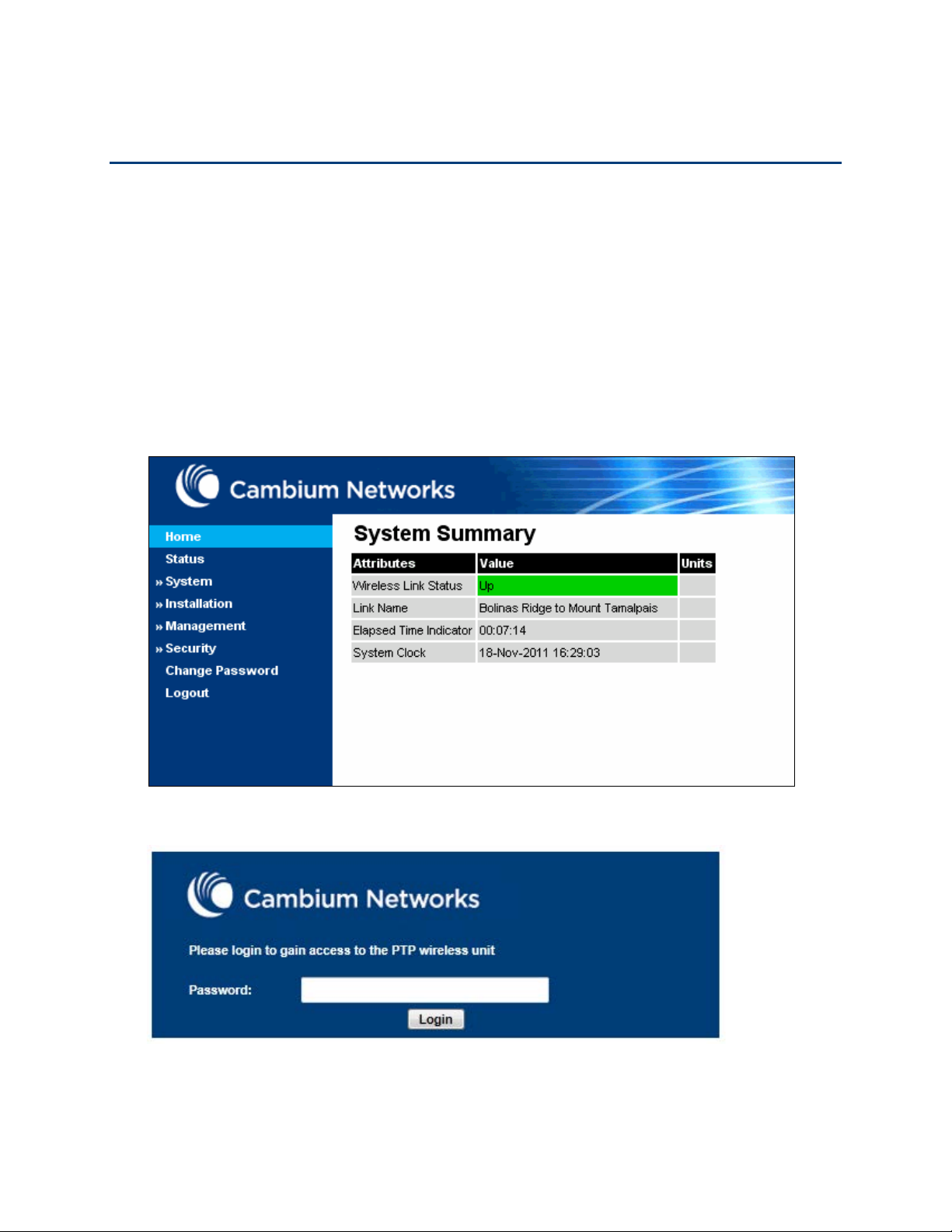
. Press ENTER. The web interface menu and System Summary page are displayed:
. The login page is displayed with Password only (the default) or
identity-based user accounts have been enabled):
UNDER DEVELOPMENT
6-6
Page
and click
.

Chapter 6: Configuration and alignment Using the web interface
Table 115
Main menu
Menu option
Web page information
Using the menu options
Use the menu navigation bar in the left panel to navigate to each web page. Some of the menu
options are only displayed for specific system configurations. Use Table 115 to locate information
about using each web page.
Home
Status
System
Configuration System Configuration page on page 6-31
Spectrum Expert or
Statistics System Statistics page on page 7-45
Menu options and web pages
System Summary page on page 7-2
System Status page on page 7-3
LAN Configuration LAN Configuration page on page 6-35
QoS Configuration QoS Configuration page on page 6-43
SFP Configuration SFP Configuration page on page 6-46
TDM Configuration TDM Configuration page on page 6-48
Save and Restore Save and Restore Configuration page on page 6-
50
Spectrum management on page 7-25
Spectrum Management
Wireless Port Counters Wireless Port Counters page on page 7-50
Main Port Counters Main Port Counters page on page 7-51
Aux Port Counters Aux Port Counters page on page 7-53
SFP Port Counters SFP Port Counters page on page 7-54
SyncE Status SyncE Status page on page 7-55
Diagnostics Plotter Diagnostics Plotter page on page 7-58
CSV Download Generate Downloadable Diagnostics page on page
Software Upgrade Software Upgrade page on page 6-52
Comparing actual to predicted performance on
page 6-109
Test Ethernet packet errors reported by ODU on
page 8-6
7-59
UNDER DEVELOPMENT
6-7
Page

Chapter 6: Configuration and alignment Using the web interface
Main menu
Menu option
Web page information
Reboot Reboot Wireless Unit page on page 7-15
Installation
Installation menu on page 6-9
Graphical Install Graphical Install page on page 6-107
Management
Web Web-Based Management page on page 6-54
Local User Accounts Local User Accounts page on page 6-57
RADIUS Configuration RADIUS Configuration page on page 6-62
Login Information Login Information page on page 7-15
Web Properties Webpage Properties page on page 6-64
SNMP SNMP pages (for SNMPv3) on page 6-76
SNMP pages (for SNMPv1/2c) on page 6-86
Email Email Configuration page on page 6-67
Diagnostic Alarms Diagnostic Alarms page on page 6-69
Time Time Configuration page on page 6-70
Syslog Syslog page on page 7-21
Syslog Configuration Syslog Configuration page on page 6-74
Security
Security menu on page 6-90
Zeroize CSPs Zeroize CSPs page on page 6-101
Change
Change Password page on page 7-16
Password
Logout
Logging out on page 7-16
UNDER DEVELOPMENT
6-8
Page

Chapter 6: Configuration and alignment Installation menu
Caution
Installation
Installation menu
This section describes how to use the Installation Wizard to complete the essential system
configuration tasks that must be performed on a new link.
If the system designer has provided a list of channels to be barred for TDWR radar
avoidance, the affected channels must be barred before the units are allowed to
radiate on site, otherwise the regulations will be infringed. To bar these channels,
follow the procedure Barring channels on page 7-39.
Starting the Installation Wizard
To start the Installation Wizard: on the menu, click
state of the unit:
• If the unit is newly installed, the Software License Key page is displayed. Continue at Software
License Key page on page 6-11.
• If the unit is armed for alignment, the Disarm Installation page is displayed. Continue at Disarm
Installation page on page 6-10.
• If the unit is not armed, the Current Installation Summary page is displayed. Continue at
Current Installation Summary page on page 6-10.
. The response depends upon the
UNDER DEVELOPMENT
6-9
Page
Chapter 6: Configuration and alignment Installation menu
Installation
Figure 107
Disarm Installation Agent
Installation
Figure 108
Continue to Installation Wizard
Disarm Installation page
Menu option:
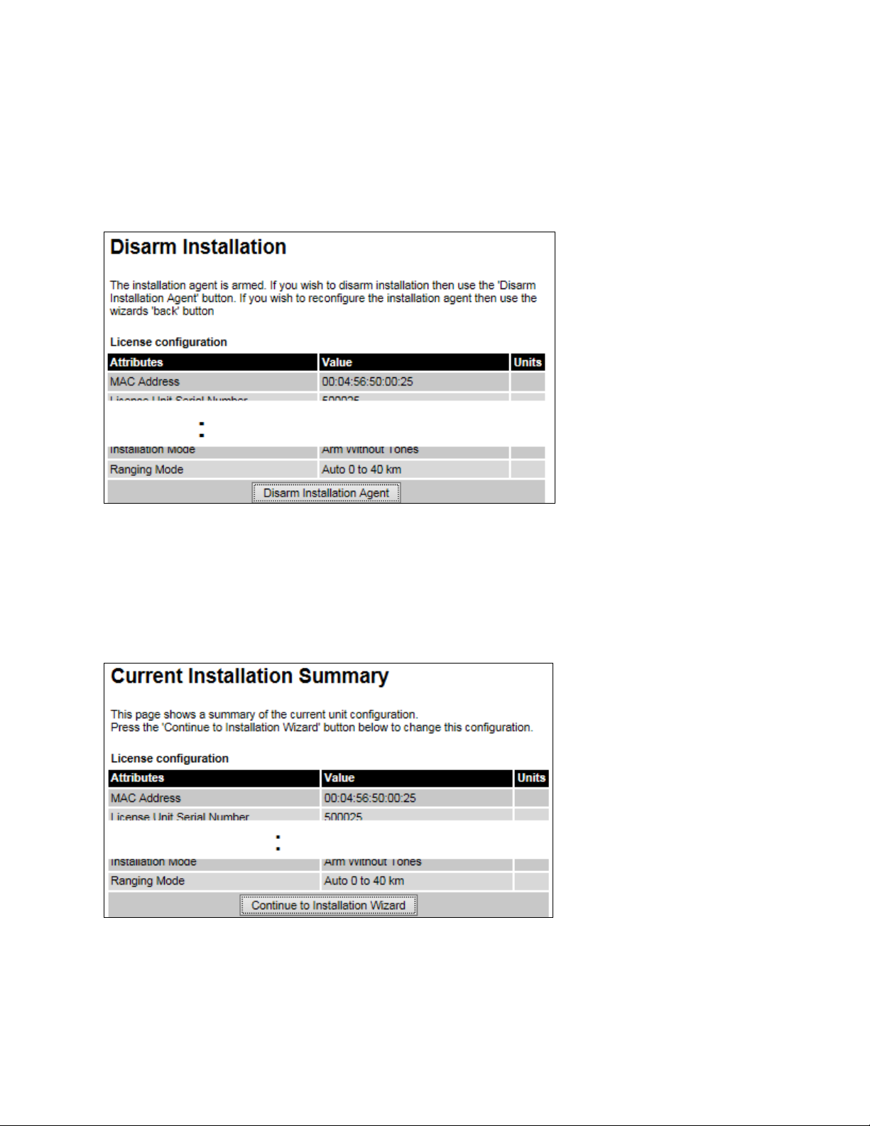
To disarm the unit, click
Disarm Installation page (top and bottom of page shown)
(Figure 107). This page is displayed only when unit is armed.
.
Current Installation Summary page
Menu option:
Click
Current Installation Summary page (top and bottom of page shown)
(Figure 108). This page is displayed only when unit is not armed.
.
UNDER DEVELOPMENT
6-10
Page
Chapter 6: Configuration and alignment Installation menu
Installation
Figure 109
Software License Key page
Menu option:
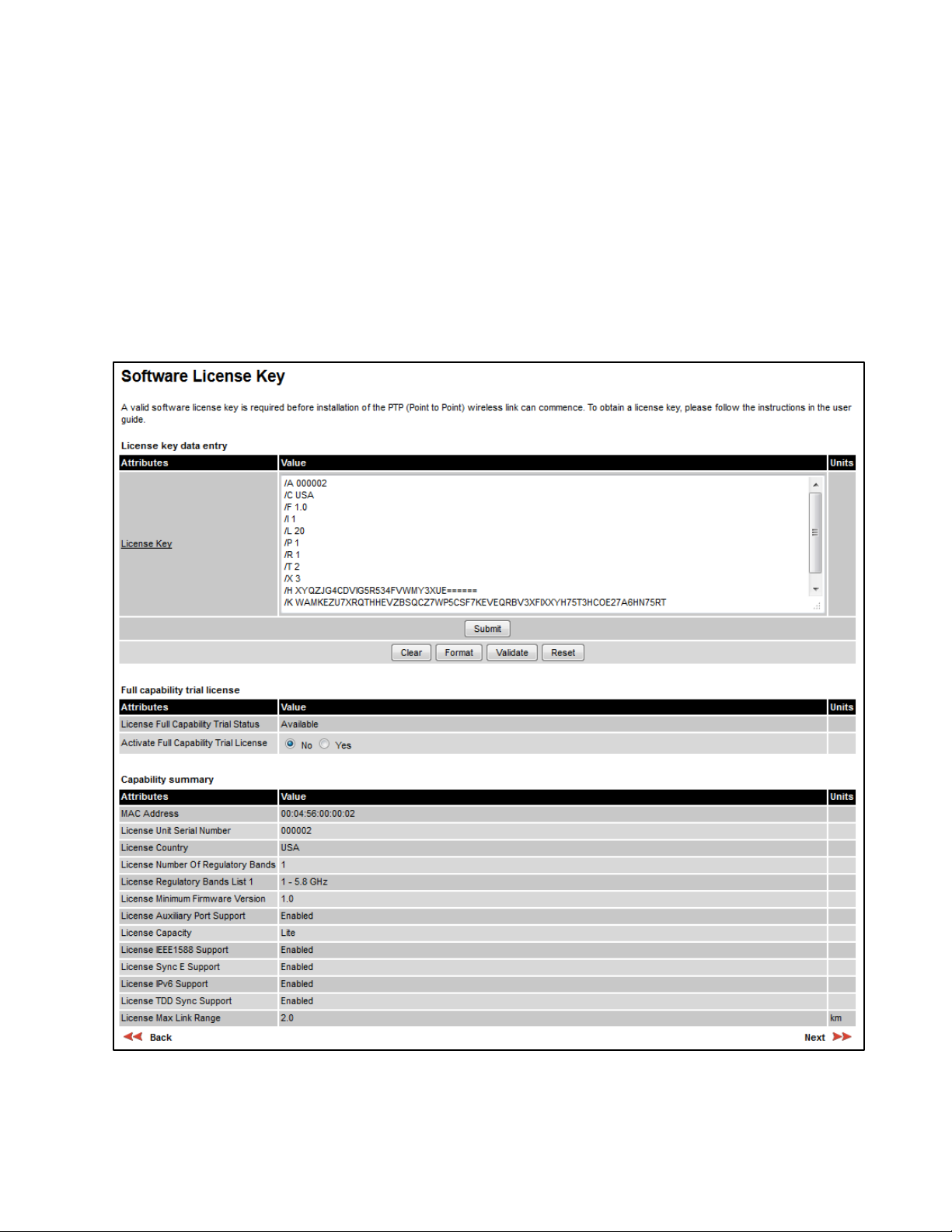
the capabilities of an installed License Key. The appearance of this page varies depending upon
which capabilities are enabled by the entered license key. For example,
licensed capabilities for a PTP 650S in the USA market with a Full Capability Trial License, whereas
Figure 110 shows TDM support, IPv6 and other capabilities. Use the Cambium Networks License
Key Generator to generate new License Keys (Generating license keys on page 6-3).
Software License Key page (PTP 650S USA market)
. Use this page to configure the unit with a new License Key and to review
Figure 109 shows the
UNDER DEVELOPMENT
6-11
Page
Chapter 6: Configuration and alignment Installation menu
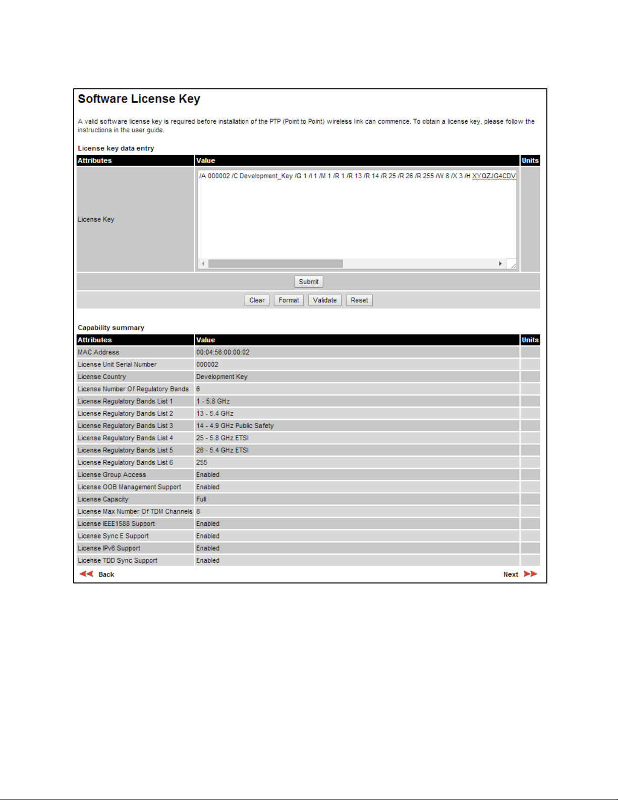
Figure 110
Software License Key page (TDM, IPv6 and other capabilities)
UNDER DEVELOPMENT
6-12
Page

Chapter 6: Configuration and alignment Installation menu
Procedures:
Note
Clear
Format
Submit
Available
Yes
Active
Yes
Inactive
Yes
Next
Figure 111
Figure 112
Figure 113
Full capability is available only when both ODUs have the trial active or are already
licensed to operate with that capacity.
When the trial has started, the Software License Key page displays the Trial Period
Remaining attribute (Figure 112). This shows the number of days remaining before the
full capability trial period expires.
To enter a new License Key, proceed as follows:
• To clear the existing License Key (if present), click
.
• To format the new License Key: copy it from the Cambium notification email, paste it into the
License Key box and click
• To enter the new License Key, click
. The page is redisplayed with the License Key formatted.
. The page is redisplayed with the Capability
Summary updated.
To control the full capability trial (Lite and Mid licenses only), proceed as follows:
• If License Full Capability Trial Status is
period by setting Activate Full Capability Trial License to
• If License Full Capability Trial Status is
period by setting Stop Full Capability Trial License to
• If License Full Capability Trial Status is
period by setting Start Full Capability Trial License to
(Figure 111), start the full capability trial
.
(Figure 112), suspend the full capability trial
.
(Figure 113), resume the full capability trial
.
To continue with the Installation Wizard, click
Software License Key page (extract) with full capability trial available
Software License Key page (extract) with full capability trial active
Software License Key page (extract) with full capability trial inactive
.
UNDER DEVELOPMENT
6-13
Page
Chapter 6: Configuration and alignment Installation menu
Installation
Caution
Note
Note
None
Note
Note
Procedure:
Next
Submit Interface Configuration
Interface Configuration page
Menu option:
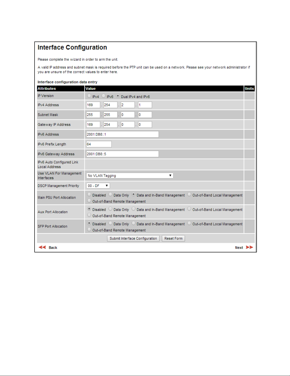
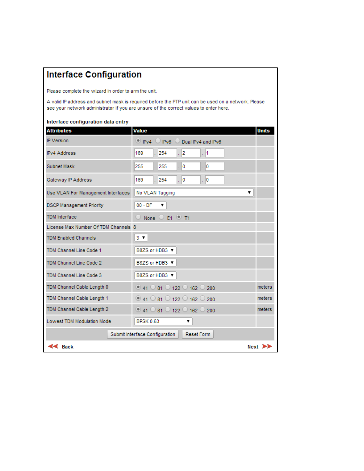
The appearance of this page varies depending upon which capabilities have been enabled by
license key. For example, Figure 114 shows the attributes that are displayed when IPv6, Aux Port,
SFP Port and Out-of-Band Management support are enabled, whereas Figure 115 shows the
attributes that are displayed when IPv6 and TDM support are enabled.
Before configuring a VLAN for management interfaces, ensure that the VLAN is
accessible, otherwise the unit will be inaccessible after the next reboot.
TDM support is only available when the following are all true:
• The installed software version is at least 50650-01-20 (Software Upgrade page on
page 6-52).
• An E1/T1 license key has been generated (Generating license keys on page 6-3)
and submitted (Software License Key page on page 6-11).
NIDUs can be installed at both link ends without enabling TDM (set TDM Interface to
). LAN data will be bridged successfully, but TDM data will be ignored.
. Use this page to update the IP interface attributes.
Synchronous Ethernet and IEEE 1588 Transparent Clock are disabled when TDM is
enabled (LAN Configuration page on page 6-35).
When TDM is enabled and connected at one link end, up to two minutes may elapse
before the TDM link is established (this is known as the settling period). Do not
attempt to change the TDM configuration during this settling period.
• Review and update the IP and VLAN attributes (Table 116).
• Review and update the TDM attributes (Table 117) (if available).
• To continue with the Installation Wizard, click
or
.
UNDER DEVELOPMENT
6-14
Page
Chapter 6: Configuration and alignment Installation menu
Figure 114
Interface Configuration page (IPv6, Aux, SFP and OOB support)
UNDER DEVELOPMENT
6-15
Page
Chapter 6: Configuration and alignment Installation menu
Figure 115
Interface Configuration page (TDM support)
UNDER DEVELOPMENT
6-16
Page

Chapter 6: Configuration and alignment Installation menu
Table 116
Attribute
Meaning
IPv4:
IPv6:
Dual IPv4 and IPv6:
No VLAN Tagging
IEEE 802.1Q Tagged (C-Tag, Type 8100)
IEEE 802.1ad Tagged (S-Tag or B-Tag, Type 88a8)
No VLAN Tagging
Interface Configuration attributes
IP Version The internet protocols to be supported by this ODU:
IPv4 protocols only. IPv4 attributes are displayed.
IPv6 protocols only. IPv6 attributes are displayed.
Both IPv4 and IPv6 protocols. IPv4 and IPv6
attributes are displayed.
IPV4 Address The IPv4 internet protocol address. This address is used by the
family of Internet protocols to uniquely identify this unit on a
network.
Subnet Mask The address range of the connected IPv4 network.
Gateway IP Address The IPv4 address of a computer on the current network that acts as
an IPv4 gateway. A gateway acts as an entrance and exit to frames
from and to other networks.
IPv6 Address The IPv6 internet protocol address. This address is used by the
family of Internet protocols to uniquely identify this unit on a
network.
IPv6 Prefix Length Length of the IPv6 subnet prefix (default 64 bits).
IPv6 Gateway Address The IPv6 address of a computer on the current network that acts as
an IPv6 gateway. A gateway acts as an entrance and exit to frames
from and to other networks. It is usual to use the link-local address
of the gateway.
IPv6 Auto Configured Link
Local Address
Use VLAN For
The link-local address of the IPv6 gateway (displayed only, not
updateable).
VLAN tagging options for the management interfaces:
Management Interfaces
Ensure that the configured VLAN is accessible, otherwise it will not
be possible to access the unit following the next reboot.
The PTP 650 management function is only compatible with single
VLAN tagged frames. Any management frame with two or more
tags will be ignored.
VLAN Management VID Only displayed when Use VLAN for Management Interfaces is not
set to
The VLAN VID (range 0 to 4094) that will be included in Ethernet
frames generated by the management interfaces.
.
UNDER DEVELOPMENT
6-17
Page

Chapter 6: Configuration and alignment Installation menu
Attribute
Meaning
No VLAN Tagging
Disabled
Data Only
Data and In-Band Management
Out-of-Band Local Management
Out-of-Band Remote Management
VLAN Management
Priority
DSCP Management
Priority
Main PSU Port Allocation
Only displayed when Use VLAN for Management Interfaces is not
set to
.
The VLAN priority (range 0 to 7) that will be included in Ethernet
frames generated by the management interfaces.
Differentiated Services Code Point (DSCP) value to be inserted in
the IP header of all IP datagrams transmitted by the management
interface.
This attribute is only displayed when one or both of the Aux and
SFP ports are enabled by license key.
: The port is not used.
: The port handles customer data only.
: The port handles both customer
data and network management data. It can be used to access the
web interface of the local unit, and if the wireless link is
established, the remote unit. Ensure that the local and remote
units have different IP addresses. This is the fixed allocation of the
Main PSU port when neither the Aux nor the SFP port is enabled.
: The port handles local
management data only. It can be used to access the web interface
of the local unit.
Aux Port Allocation This attribute is only displayed when the Aux port is enabled by
SFP Port Allocation This attribute is only displayed when the SFP port is enabled by
: The port handles remote
management data only. It can be used to access the web interface
of the remote unit.
For more help, see Configuring the ODU ports for customer and
management traffic on page 6-20.
license key. For definitions, see Main PSU Port Allocation.
license key. For definitions, see Main PSU Port Allocation.
UNDER DEVELOPMENT
6-18
Page

Chapter 6: Configuration and alignment Installation menu
Table 117
Attribute
Meaning
None
E1
T1
Interface Configuration TDM attributes
TDM Interface Only displayed when TDM is enabled by license key.
The type of TDM interface that is activated.
: TDM is disabled.
: The E1 TDM interface is activated.
: The T1 TDM interface is activated.
License Max Number of
TDM Channels
Only displayed when TDM Interface is set to E1 or T1.
The maximum number of TDM channels (E1 or T1) allowed under
the installed license key.
TDM Enabled Channels Only displayed when TDM Interface is set to E1 or T1.
Select the number of E1 or T1 channels that are to be enabled over
the wireless bridge (1 to 8).
TDM Channel Line Code n Only displayed when TDM Interface is set to E1 or T1.
Select the line code of the transceiver connected to NIDU E1/T1
channel “n” (where “n” is in the range 1 to 8).
TDM Channel Cable
Length n
Only displayed when TDM Interface is set to T1.
This control compensates for the high frequency attenuation in T1
cables. Equalization is automatic in the E1 interface.
Select the nearest approximation to the length of cable connecting
the transceiver to NIDU T1 channel “n” (where “n” is in the range
1 to 8).
Lowest TDM Modulation
Mode
Only displayed when TDM Interface is set to E1 or T1.
The lowest modulation mode at which TDM data can be sent. If
the link cannot sustain TDM data in this mode then the effective
lowest modulation mode may differ.
In conjunction with the PTP LINKPlanner tool, this setting may be
used to optimize the latency for links which operate in consistently
high modulation modes. High data rate links are able to support
lower latencies.
UNDER DEVELOPMENT
6-19
Page

Chapter 6: Configuration and alignment Installation menu
1
Set all enabled ports (Main PSU, Aux and SFP) to Disabled
error message.
2
Choose
•
None
•
E1
For In
Date and In-Band
Management
Data Only
3
For
of the remaining ports (Main PSU, Aux or
SFP)
Out-of-Band Local Management
This setting is compatible with
Date and In-Band
Management
Data Only
4
For Out
or SFP) to Out-of-Band Remote Management
•
Date and In-Band Management
Out-of-Band Remote Management
•
Out-of-Band Remote Management
5
Check that at least one port has been set to either Date and In-Band Management
Out-of-
Band Local Management
Out-of-Band Remote Management
described in the above steps).
Configuring the ODU ports for customer and management traffic
Use this procedure to achieve a correct combination of settings of the Port Allocation attributes
(Main PSU, Aux and SFP). The valid port allocation combinations are summarized in Table 118.
In the course of this procedure, the system will display one or more error messages that start with
“Please check your port allocations“ and end with one of the following:
• “there must be exactly one port configured to pass data”
• “there are no ports configured for management”
• “you cannot configure both In-Band and Out-of-Band Remote Management”
• “there are too many ports configured for Out-of-Band Remote Management”
When this happens, click OK and continue. If the procedure is followed correctly, no error message
will be displayed on completion.
To allocate the ODU ports to customer and management traffic, proceed as follows:
and click OK in response to the
exactly one port to carry customer data, subject to the following restrictions:
If TDM is not available or the TDM Interface attribute is set to
enabled ports to carry customer data (Main PSU, Aux or SFP)
If the TDM Interface attribute is set to either
carry customer data
-Band management, set the chosen customer data port to
, otherwise set it to
Out-of-Band Local management, set one or both
to
or
-of-Band Remote management, set exactly one of the remaining ports (Main PSU, Aux
If the customer data port is set to
Do not set more than one port to
.
.
.
a customer data port setting of either
.
.
or
If this is not the case, then review and correct the allocations.
or T1, choose only the Main PSU port to
, subject to the following restrictions:
(subject to the restrictions
, choose any one of the
.
, do not set any port to
.
or
UNDER DEVELOPMENT
6-20
Page

Chapter 6: Configuration and alignment Installation menu
Table 118
Number of ports
Customer data port (*1)
Other port 1 (*2)
Other port 2 (*2)
Valid port allocation combinations
2 Data Only Out-of-Band Local -
2 Data Only Out-of-Band Remote -
2 Date and In-Band Out-of-Band Local -
2 Date and In-Band Disabled -
3 Data Only Out-of-Band Local Disabled
3 Data Only Out-of-Band Remote Disabled
3 Data Only Out-of-Band Local Out-of-Band Local
3 Data Only Out-of-Band Local Out-of-Band Remote
3 Date and In-Band Out-of-Band Local Disabled
3 Date and In-Band Out-of-Band Local Out-of-Band Local
3 Date and In-Band Disabled Disabled
(*1) The port allocated to customer data (one of Main PSU, Aux or SFP).
(*2) The ports not allocated to customer data (Main PSU, Aux or SFP).
UNDER DEVELOPMENT
6-21
Page
Chapter 6: Configuration and alignment Installation menu
Installation
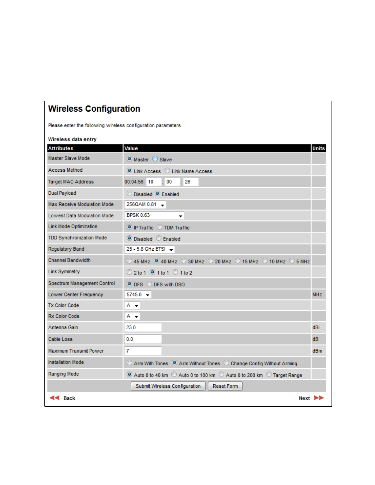
Figure 116
Wireless Configuration page
Menu option:
This page is part of the Installation Wizard. Use it to update the wireless attributes.
Wireless Configuration page
(Figure 116).
UNDER DEVELOPMENT
6-22
Page

Chapter 6: Configuration and alignment Installation menu
Procedure:
Next
Submit
Wireless Configuration
Caution
Note
Master
Slave
Table 119
Attribute
Meaning
Master:
Slave:
Link Access:
Link Name Access:
Group Access:
Link Access
• Update the attributes (Table 119).
• To save any changes and continue with the Installation Wizard, click
.
The lower center frequency attribute must be configured to the same value for both
the Master and Slave, otherwise the wireless link will fail to establish. The only way to
recover from this situation is to modify the Lower Center Frequency attributes so that
they are identical on both the master and slave units.
When configuring a linked pair of units, use the Master Slave Mode to ensure that
one unit is
and the other is
.
Master Slave Mode
Wireless Configuration attributes
The unit controls the point-to-point link and its maintenance. On
startup, the Master transmits until a link with the Slave is made.
The unit listens for its peer and only transmits when the peer has
been identified.
or click
Access Method ODUs must be configured in pairs before a link can be established. Access
Target MAC Address Only displayed when Access Method is set to
Method determines how paired ODUs will recognize each other.
Each ODU must be configured with Target MAC Address
equal to the MAC Address of the other unit.
Both ODUs must be configured with the same Link
Name.
Only displayed when a Group Access license key has been
generated (
Generating license keys on page 6-3) and submitted (Software
License Key page on page 6-11). Both ODUs must be configured with the
same Group ID attributes.
. This is the
MAC Address of the peer unit that will be at the other end of the wireless
link. This is used by the system to ensure the unit establishes a wireless
link to the correct peer. The MAC Address can be found embedded within
the serial number of the unit. The last six characters of the serial number
are the last three bytes of the unit’s MAC address.
Page
6-23
UNDER DEVELOPMENT

Chapter 6: Configuration and alignment Installation menu
Attribute
Meaning
Link Name Access
Group Access
Disabled:
Enabled:
IP Traffic:
TDM Traffic:
Disabled:
Enabled:
Enabled
1 to 1.
Link Name Only displayed when Access Method is set to
Link Name may consist of letters (A-Z and a-z), numbers (0-9), spaces, and
the following special characters: (),-.,:<=>[]_{}
Link Name must be same at both ends and different to site name.
Group Id Only displayed when Access Method is set to
only be established between units that have identical Group IDs.
Dual Payload
The link maximizes robustness against fading and interference.
The link attempts to reach maximum throughput at the expense
of robustness against fading and interference.
Max Receive
Modulation Mode
The maximum mode the unit will use as its adaptive modulation. By
default the Max Receive Modulation Mode is the highest mode available.
For minimum error rates, set the maximum modulation mode to the
minimum necessary to carry the required traffic.
Lowest Data
Modulation Mode
The lowest modulation mode that must be achieved before the link is
allowed to bridge customer data Ethernet frames. This does not affect the
bridging of management data: if out-of-band remote management is
enabled, this will continue regardless of modulation mode.
Link Mode
Optimization
possible link capacity.
The link is optimized for IP traffic to provide the maximum
.
. A link can
The link is optimized for TDM traffic to provide the lowest
possible latency. This is the only available setting when TDM is enabled
Interface Configuration page on page 6-14).
(
TDD
Synchronization
Mode
Installation Wizard; see
The link does not employ TDD synchronization.
The link employs TDD synchronization. This is configured in the
TDD synchronization page (optional) on page 6-
28. For a basic description, see TDD synchronization on page 1-19.
When TDD Synchronization Mode is set to
, the following
restrictions apply: Ranging Mode and Target Range are disabled, and Link
Symmetry is limited to
Regulatory Band The regulatory band selected from the list in the license key.
Channel Bandwidth Bandwidth of the transmit and receive radio channels.
UNDER DEVELOPMENT
Page
6-24

Chapter 6: Configuration and alignment Installation menu
Attribute
Meaning
Master
Adaptive
TDM Traffic
“2 to 1”
1 to 1”
1 to 2”
2 to 1”
1 to 2”
1 to 1
DSO
Fixed Frequency
DFS
DFS with DSO
Fixed Frequency
Fixed Frequency
Fixed Frequency
Link Symmetry Only displayed when Master Slave Mode is set to
: Allows link symmetry to vary dynamically in response to
offered traffic load. This is not supported in the following cases:
• Where radar avoidance is mandated in the region.
• Link Mode Optimization is set to
, “
or “
: There is a fixed division between transmit
and receive time in the TDD frame of the master ODU. The first number in
the ratio represents the time allowed for the transmit direction and the
second number represents the time allowed for the receive direction. The
appropriate matching Link Symmetry is set at the slave ODU
automatically. For example, if Link Symmetry is set to “
master ODU, then the slave ODU will be set automatically as “
this example, the master-slave direction has double the capacity of the
slave-master direction.
When TDM is enabled (Interface Configuration page on page 6-14), Link
”.
Spectrum
Symmetry is limited to “
In regions that do not mandate DFS (radar detection), the options are:
Management
Control
.
.
at the
. In
Lower Center
Frequency
Default Raster This is only displayed when Spectrum Management Control is set to
Fixed Tx Frequency,
Fixed Rx Frequency
In regions that mandate DFS (radar detection), the options are:
This attribute is disabled if the regulatory requirement is fixed frequency
only.
The center frequency (MHz) of the lowest channel that may be used by
this link. Not displayed when Spectrum Management Control is set to
.
Use this attribute to slide the available channels up and down the band.
. Limits frequency selection to the unit’s default raster
setting.
This is only displayed when Spectrum Management Control is set to
. The settings must be compatible at each end of the link.
Once configured, the spectrum management software will not attempt to
move the wireless link to a channel with lower co-channel or adjacent
channel interference. Therefore this mode of operation is only
recommended for deployments where the installer has a good
understanding of the prevailing interference environment.
UNDER DEVELOPMENT
6-25
Page

Chapter 6: Configuration and alignment Installation menu
Attribute
Meaning
A
Arm With Tones
Arm Without Tones
Change Config Without Arming
Tx Color Code, Rx
Color Code
Tx Color Code and Rx Color Code may be used to minimize interference
in a dense network of synchronized PTP 650 units where some of the
units are operating on the same frequency. When this type of network is
designed, the Color Code values are normally specified in the link
planning report. In all other cases, Cambium Networks recommend that
Tx Color Code and Rx Color Code are left at the default value of
The value of Tx Color Code MUST always match the value of Rx Color
Code at the other end of the link.
Antenna Gain Only displayed when the ODU is connectorized.
Gain of the remote antenna.
Cable Loss Only displayed when the ODU is connectorized.
Loss in the ODU-antenna RF cable. If there is a significant difference in
length of the RF cables for the two antenna ports, then the average value
should be entered.
Maximum Transmit
Power
The maximum power (dBm) at which the unit will transmit, configurable
in steps of 1 dB. Its maximum value is controlled by the selected
combination of Regulatory Band, Bandwidth and (for connectorized units)
Antenna Gain and Cable Loss.
To prepare for antenna alignment, set this attribute to the alignment value
specified in the installation report (PTP LINKPlanner).
.
Installation Mode
To prepare for link operation, set this attribute to the operational value
specified in the installation report (PTP LINKPlanner). This may be higher
than the alignment value.
: Audio tones will be emitted during antenna alignment
(the recommended option).
: Audio tones will not be emitted during antenna
alignment.
: Configuration changes will be made
without arming the ODU for alignment.
Page
6-26
UNDER DEVELOPMENT

Chapter 6: Configuration and alignment Installation menu
Attribute
Meaning
Arm With Tones
Arm
Without Tones
Auto..
Auto 0 to 40 km
Auto 0 to 100km
Auto 0 to 200km
Target Range
Target Range
Ranging Mode This can only be modified if Installation Mode is
.
: During alignment, the wireless units use algorithms to calculate
link range. To implement automatic ranging, select a value that
corresponds to the estimated maximum range of the link:
(0 to 25 miles).
(0 to 62 miles).
(0 to 125 miles).
: During alignment, the wireless units use the approximate
link distance (entered in Target Range) to calculate link range. The main
advantage of Target Range mode is that it reduces the time taken by the
units to range.
If preferred, range functions can be configured to operate in miles, as
described in Webpage Properties page on page 6-64.
Target Range Only available when Ranging Mode is set to
The approximate distance between the two wireless units to within
± 1 km. Enter the same value at both ends of the link.
or
.
UNDER DEVELOPMENT
Page
6-27
Chapter 6: Configuration and alignment Installation menu
Enabled
Procedure:
Next
Figure 117
Note
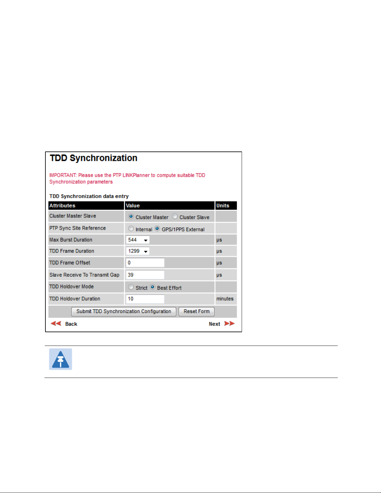
TDD synchronization page (optional)
If TDD Synchronization Mode is set to
3: TDD Synchronization page (
For more information on the available options, refer to Configuration options for TDD
synchronization on page 3-31.
• Update the attributes (Table 120).
• Click
.
Step 3: TDD Synchronization page
Figure 117) is the third Installation Wizard page.
in the Step 2: Wireless Configuration page, the Step
The data required to populate this page is available in PTP LINKPlanner.
UNDER DEVELOPMENT
6-28
Page

Chapter 6: Configuration and alignment Installation menu
Table 120
Attribute
Meaning
Cluster Master
Cluster Slave
Internal
GPS/1PPS External
544
2176
1299
2747
Cluster Master
Strict
Best Effort
Cluster Master
10
Cluster Master Slave
TDD Synchronization attributes
: The first ODU in the synchronization chain.
: The second or subsequent ODU in the chain.
PTP-SYNC Site
Reference
: Standalone operation with no external timing reference.
: An external GPS receiver will provide a 1 pps timing
reference.
Max Burst Duration The maximum duration of the burst opportunity. Select a value in the range
to
TDD Frame Duration Select a value in the range
microseconds.
to
microseconds.
TDD Frame Offset The delay of the start of the TDD frame from the epoch of the external timing
reference. This permits the design of synchronized networks in which the
phase of the TDD frame is independent of the master/slave function. Enter a
value in the range from zero to one microsecond less than the TDD Frame
Duration.
Slave Receive To
The duration of the gap between receive and transmit at the slave ODU.
Transmit Gap
TDD Holdover Mode Only displayed when Cluster Master Slave is set to
: The unit will not transmit when synchronization is lost.
: The unit will synchronize when there is a reference signal, but
otherwise will operate in unsynchronized mode.
TDD Holdover
Duration
Only displayed when Cluster Master Slave is set to
Specifies duration of holdover period following loss of the external timing
reference for TDD synchronization. Default value
minutes.
.
.
minutes, maximum 60
UNDER DEVELOPMENT
Page
6-29
Chapter 6: Configuration and alignment Installation menu
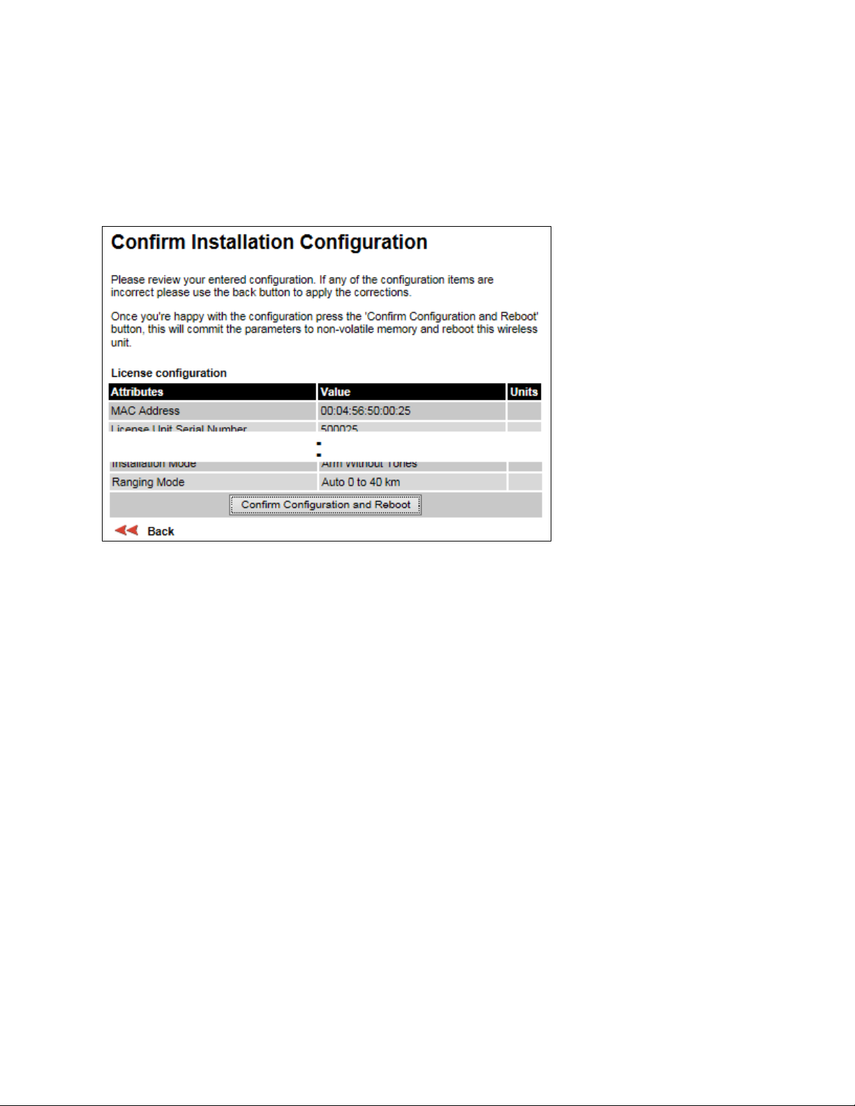
Installation
Figure 118
Procedure:
Back
Confirm Configuration and Reboot
OK
Confirm Installation Configuration page
Menu option:
configuration of the unit.
Confirm Installation Configuration page (top and bottom of page shown)
(Figure 118). Use this page to review and confirm the updated wireless
• To undo or correct any updates, click
• To confirm the updates and arm the installation, click
click
• If IP Address, Subnet Mask or Gateway IP Address have been changed: reconfigure the local
management PC to use an IP address that is valid for the network. Refer to Configuring the
management PC on page 6-4.
• If IP Address has been changed, use the new IP address to log into the unit.
to reboot the unit.
.
and
UNDER DEVELOPMENT
6-30
Page
 Loading...