

Cambium Networks 50650 Installation Guide

UNDER DEVELOPMENT
Cambium
PTP 650
Installation Guide

Accuracy
Copyrights
Restrictions
License Agreements
High Risk Materials
UNDER DEVELOPMENT
While reasonable efforts have been made to assure the accuracy of this document, Cambium
Networks assumes no liability resulting from any inaccuracies or omissions in this document, or
from use of the information obtained herein. Cambium Networks reserves the right to make
changes to any products described herein to improve reliability, function, or design, and reserves
the right to revise this document and to make changes from time to time in content hereof with
no obligation to notify any person of revisions or changes. Cambium Networks does not assume
any liability arising out of the application or use of any product, software, or circuit described
herein; neither does it convey license under its patent rights or the rights of others. It is possible
that this publication may contain references to, or information about Cambium Networks
products (machines and programs), programming, or services that are not announced in your
country. Such references or information must not be construed to mean that Cambium Networks
intends to announce such Cambium Networks products, programming, or services in your
country.
This document, Cambium Networks products, and 3rd Party software products described in this
rd
document may include or describe copyrighted Cambium Networks and other 3
Party supplied
computer programs stored in semiconductor memories or other media. Laws in the United
rd
States and other countries preserve for Cambium Networks, its licensors, and other 3
Party
supplied software certain exclusive rights for copyrighted material, including the exclusive right
to copy, reproduce in any form, distribute and make derivative works of the copyrighted
rd
material. Accordingly, any copyrighted material of Cambium Networks, its licensors, or the 3
Party software supplied material contained in the Cambium Networks products described in this
document may not be copied, reproduced, reverse engineered, distributed, merged or modified
in any manner without the express written permission of Cambium Networks. Furthermore, the
purchase of Cambium Networks products shall not be deemed to grant either directly or by
implication, estoppel, or otherwise, any license under the copyrights, patents or patent
applications of Cambium Networks or other 3rd Party supplied software, except for the normal
non-exclusive, royalty free license to use that arises by operation of law in the sale of a product.
Software and documentation are copyrighted materials. Making unauthorized copies is
prohibited by law. No part of the software or documentation may be reproduced, transmitted,
transcribed, stored in a retrieval system, or translated into any language or computer language,
in any form or by any means, without prior written permission of Cambium Networks.
The software described in this document is the property of Cambium Networks and its licensors.
It is furnished by express license agreement only and may be used only in accordance with the
terms of such an agreement.
Cambium and its supplier(s) specifically disclaim any express or implied warranty of fitness for
any high risk activities or uses of its products including, but not limited to, the operation of
nuclear facilities, aircraft navigation or aircraft communication systems, air traffic control, life
support, or weapons systems (“High Risk Use”). Any High Risk is unauthorized, is made at your
own risk and you shall be responsible for any and all losses, damage or claims arising out of any
High Risk Use.

UNDER DEVELOPMENT
About this guide
This guide is supplied with PTP 650 ODUs. It describes how to install the site equipment for
PTP 650 Series links. Users of this guide require expertise in outdoor radio equipment
installation.
Related documents
For full PTP 650 installation planning instructions, refer to the PTP 650 Series User Guide.
Version information
Document number and version: phn-3350_000v002.
Date of publication: July 2013.
Waste Electrical and Electronic Equipment (WEEE)
For instructions on waste disposal of used products, refer to
http://www.cambiumnetworks.com/support
Page 1

UNDER DEVELOPMENT
Warning
Safety
To prevent loss of life or physical injury, observe the below safety guidelines. In no event shall
Cambium Networks be liable for any injury or damage caused during the installation of the
Cambium PTP 650. Ensure that only qualified personnel install a PTP 650 link.
Power lines
Exercise extreme care when working near power lines.
Working at heights
Exercise extreme care when working at heights.
Grounding and protective earth
The Outdoor Unit (ODU) must be properly grounded to protect against lightning. It is the user’s
responsibility to install the equipment in accordance with national regulations. In the USA,
follow Section 810 of the National Electric Code, ANSI/NFPA No.70-1984 (USA). In Canada, follow
Section 54 of the Canadian Electrical Code. These codes describe correct installation procedures
for grounding the outdoor unit, mast, lead-in wire and discharge unit, size of grounding
conductors and connection requirements for grounding electrodes. Other regulations may apply
in different countries and therefore it is recommended that installation of the outdoor unit be
contracted to a professional installer.
PSU
Always use one of the Cambium PTP 650 Series power supply units (PSU) to power the ODU.
Failure to use a Cambium supplied PSU could result in equipment damage and will invalidate
the safety certification and may cause a safety hazard.
Alternative DC supplies
If an AC supply is not required or an additional back up DC supply is required, the DC supply is
connected to the PSU DC IN terminals. This is the only method of supplying external DC to the
ODU. The DC supply must comply with the following requirements:
• The voltage and polarity is correct and is applied to the correct PIDU terminals.
• The power source is rated as Safety Extra Low Voltage (SELV).
• The power source is rated to supply at least 1A continuously.
• The power source cannot provide more than the Energy Hazard Limit as defined by
IEC/EN/UL60950-1, Clause 2.5, Limited Power (The Energy Hazard Limit is 240VA).
Page 2

UNDER DEVELOPMENT
Powering down before servicing
Always power down and unplug the equipment before servicing.
Lightning protection unit (LPU)
Hazardous voltages are present within the LPU. Do not remove the insulation tape or printed
circuit board when the LPU is connected to the power supply.
Primary disconnect device
The main power supply is the primary disconnect device.
External cables
Safety may be compromised if outdoor rated cables are not used for connections that will be
exposed to the outdoor environment.
Drop cable tester
The drop cable tester must NEVER be used at the ODU end connected to power from the PIDU.
It must only be used at the bottom of the mast with a multimeter. This is because the PIDU
voltage exceeds the limit allowed in some countries for safe handling in wet conditions and
therefore may create a safety hazard.
RF exposure near the antenna
Strong radio frequency (RF) fields will be present close to the antenna when the transmitter is
on. Always turn off the power to the ODU before undertaking maintenance activities in front of
the antenna.
Minimum separation distances
Ensure that personnel are not exposed to unsafe levels of RF energy. The units start to radiate as
soon as they are powered up. Never work in front of the antenna when the ODU is powered.
Install the ODUs so as to provide and maintain the minimum separation distances from all
persons. For minimum separation distances, see the PTP 650 Series User Guide.
Before connecting or disconnecting the drop cable from the PSU or ODU, always power down
the PSU.
Grounding and lightning protection requirements
Ensure that the installation meets the requirements defined in the PTP 650 Series User Guide.
Page 3

UNDER DEVELOPMENT
Grounding cable installation methods
When routing, fastening and connecting grounding cables, the following requirements must be
met:
• Grounding conductor runs are as short, straight and smooth as possible, with bends and
curves kept to a minimum.
• Grounding cables must not be installed with drip loops.
• All bends must have a minimum radius of 203 mm (8 in) and a minimum angle of 90°. A
diagonal run is preferable to a bend, even though it does not follow the contour or run
parallel to the supporting structure.
• All bends, curves and connections must be routed towards the grounding electrode system,
ground rod, or ground bar.
• Grounding conductors must be securely fastened.
• Braided grounding conductors must not be used.
• Approved bonding techniques must be used for the connection of dissimilar metals.
Siting ODUs and antennas
ODUs and external antennas are not designed to survive direct lightning strike. For this reason
they must be installed in Zone B as defined in PTP 650 Series User Guide. Mounting in Zone A
may put equipment, structures and life at risk.
Optical SFP module
The optical SFP module is a Class 1 Laser product. When installing it, observe the following
safety precautions:
• Do not look into the source of the laser beam (optical receptacle) directly or through an
optical system, as this is highly likely to damage vision.
• Always remove power from the system before the optical connection is made or unmade.
• When installing the optical interface, either cap the optical connector, or mate the connector
to an appropriate equipment connector.
• Ensure that the indoor end of the optical cable is appropriately labeled to ensure that service
personnel are aware the same Class 1 Laser hazard exists.
Page 4

UNDER DEVELOPMENT
Cambium description
Cambium part number
Cambium description
Cambium part number
Components
ODUs
For ODU part numbers, refer to the PTP 650 Series User Guide.
PSUs and line cords
The ODU kits (but not single ODUs) are supplied with one PSU and one US or EU line cord as
appropriate. Cambium Networks supply additional PSUs and line cords as follows:
AC Power Injector N000065L001
AC+DC Power Injector Extended Temperature and Capacity (*) C000065L002
US Line Cord Fig 8 N000065L003
UK Line Cord Fig 8 N000065L004
EU Line Cord Fig 8 N000065L005
Australia Line Cord Fig 8 N000065L006
(*) The AC+DC Power Injector is required if the ODU has an AUX interface.
Connectorized ODU accessories
For connectorized ODUs, Cambium Networks supply RF cable and connectors as follows:
50 Ohm Braided Coaxial Cable - 75 meter 30010194001
50 Ohm Braided Coaxial Cable - 500 meter 30010195001
RF CONNECTOR,N,MALE,STRAIGHT FOR CNT-400 CABLE 09010091001
Page 5

UNDER DEVELOPMENT
Caution
Note
Note
Cambium description
Cambium part number
Cambium description
Cambium part number
Copper Cat5e Ethernet cable and LPUs
Always use Cat5e cable that is gel-filled and shielded with copper-plated steel. Alternative
types of drop cable are not supported by Cambium Networks.
The parts listed work with Superior Essex type BBDGe cable (as supplied by Cambium
Networks). They may not work with other types of cable.
Five EMC strain relief cable glands are included in the LPU and grounding kit.
Cambium Networks supply Cat5e Ethernet cable and LPUs as follows:
1000 ft Reel Outdoor Copper Clad CAT5E WB3175
328 ft (100 m) Reel Outdoor Copper Clad CAT5E WB3176
Cable Grounding Kits For 1/4" And 3/8" Cable 01010419001
Tyco/AMP, Mod Plug RJ45, 100 pack WB3177
Tyco/AMP Crimp Tool WB3211
RJ-45 Gland Spare – PG16 style (Qty. 10) N000065L033
PTP 650 LPU and Grounding Kit C000065L007
SFP modules
Cambium Networks supplie SFP modules as follows:
PTP 650 Optical 1000BaseLX Ethernet SFP Module (*1) C000065L008
PTP 650 Optical 1000BaseSX Ethernet SFP Module (*1) C000065L009
PTP 650 Twisted Pair 1000BaseT Ethernet SFP Module C000065L010
(*1) Order optical cable from a specialist, quoting the optical cable specification in the PTP 650
Series User Guide.
Page 6
UNDER DEVELOPMENT
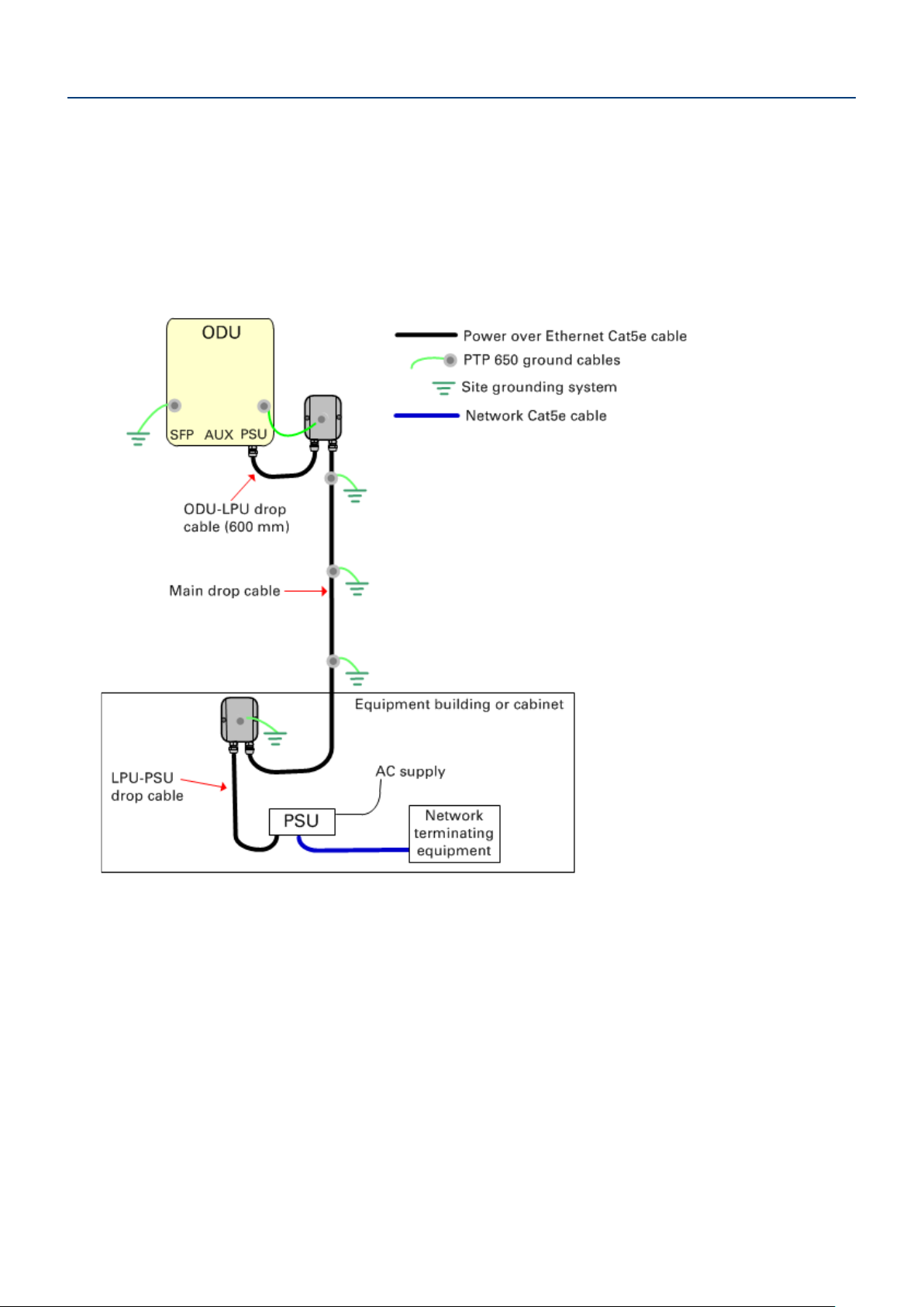
Typical deployment
A PTP 650 site typically consists of a high supporting structure such as a mast, tower or building
for the outdoor equipment (ODU and optional external antenna); and an equipment building or
moisture-proof enclosure for the indoor equipment (PSU).
In the basic configuration, there is only one Ethernet interface, a copper Cat5e connection from
the ODU (PSU port) to the PSU and network terminating equipment, as shown here:
Page 7
UNDER DEVELOPMENT
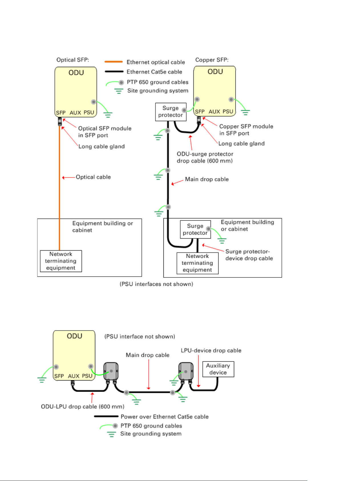
In more advanced configurations, there may be an optical or copper Cat5e SFP Ethernet interface
(unpowered) into the ODU (SFP port):
In more advanced configurations, there may be a copper Cat5e interface (with optional power
over Ethernet) into the ODU (AUX port):
Page 8
UNDER DEVELOPMENT
Note
Installing the ODU and top LPU
If LPUs are being installed, use only the five EMC cable glands supplied in the LPU and
grounding kit (with black caps). Discard the non-EMC cable glands supplied in the ODU
kits (with silver caps), as these may only be used in PTP 650 installations without LPUs.
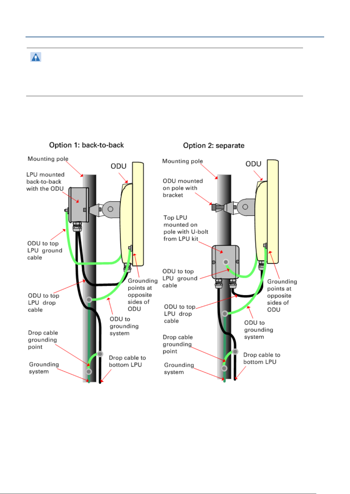
ODU and top LPU mounting options
Select one of two mounting options for the ODU and top LPU:
The AUX interface requires its own LPUs. The copper SFP interface requires its own surge
arrestors (not PTP 650 LPUs). The optical SFP interface does not require LPUs or ground cables.
Page 9
UNDER DEVELOPMENT
Caution
Note
1
Mounting the ODU and top LPU
Do not over-tighten the ODU mounting bracket bolts, as this may lead to failure of the
assembly.
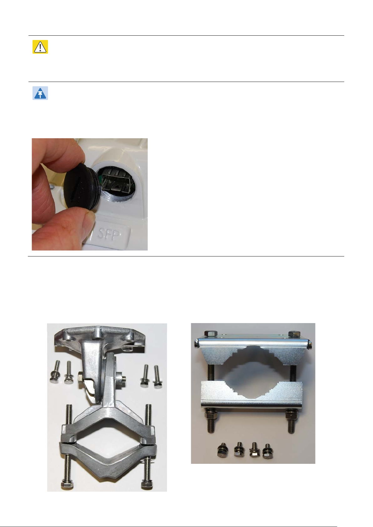
ODUs are shipped with blanking plugs protecting the PSU, AUX and SFP ports. Use a large flat
blade screwdriver to remove the plugs from those ports that will be connected to interface
cables:
Confirm that the correct mounting bracket kit has been supplied:
Integrated ODU
Connectorized ODU
Page 10
 Loading...