

Cambium Networks 50450M User Guide

Chapter 7: Configuration
This chapter describes how to use the web interface to configure the PMP/PTP 450 platform link.
This chapter contains the following topics:
Preparing for configuration on page 7-72
Connecting to the unit on page 7-73
Using the web interface on page 7-75
Quick link setup on page 7-81
Configuring IP and Ethernet interfaces on page 7-92
Upgrading the software version and using CNUT on page 7-135
General configuration on page 7-139
Configuring Unit Settings page on page 7-157
Setting up time and date on page 7-161
Configuring synchronization on page 7-163
Configuring security on page 7-165
Configuring radio parameters on page 7-192
Setting up SNMP agent on page 7-242
Configuring syslog on page 7-249
Configuring remote access on page 7-255
Monitoring the Link on page 7-256
Configuring quality of service on page 7-259
Installation Color Code on page 7-272
Zero Touch Configuration Using DHCP Option 66 on page 7-273
Configuring Radio via config file on page 7-279
Configuring a RADIUS server on page 7-281
Page 7-71

Chapter 7: Configuration
Preparing for configuration
Warning
Ensure that personnel are not exposed to unsafe levels of RF energy. The units start to
radiate RF energy as soon as they are powered up. Respect the safety standards
defined in Compliance with safety standards on page 4-22, in particular the minimum
separation distances.
Observe the following guidelines:
Never work in front of the antenna when the ODU is powered.
Always power down the PSU before connecting or disconnecting the drop cable
from the PSU, ODU or LPU.
Caution
If the system designer has provided a list of channels to be barred for TDWR radar
avoidance, the affected channels must be barred before the units are allowed to
radiate on site, otherwise the regulations will be infringed.
Attention
Si le concepteur du système a fourni une liste de canaux à interdire pour éviter les
radars TDWR, les cannaux concernées doivent être interdits avant que les unités sont
autorisées à émettre sur le site, sinon la réglementation peut être enfreinte.
Preparing for configuration
This section describes the checks to be performed before proceeding with unit configuration and
antenna alignment.
Safety precautions
All national and local safety standards must be followed while configuring the units and aligning
the antennas.
Regulatory compliance
All applicable radio regulations must be followed while configuring the units and aligning the
antennas. For more information, refer to Compliance with radio regulations on page 4-31.
Page 7-72

Chapter 7: Configuration
Connecting to the unit
1
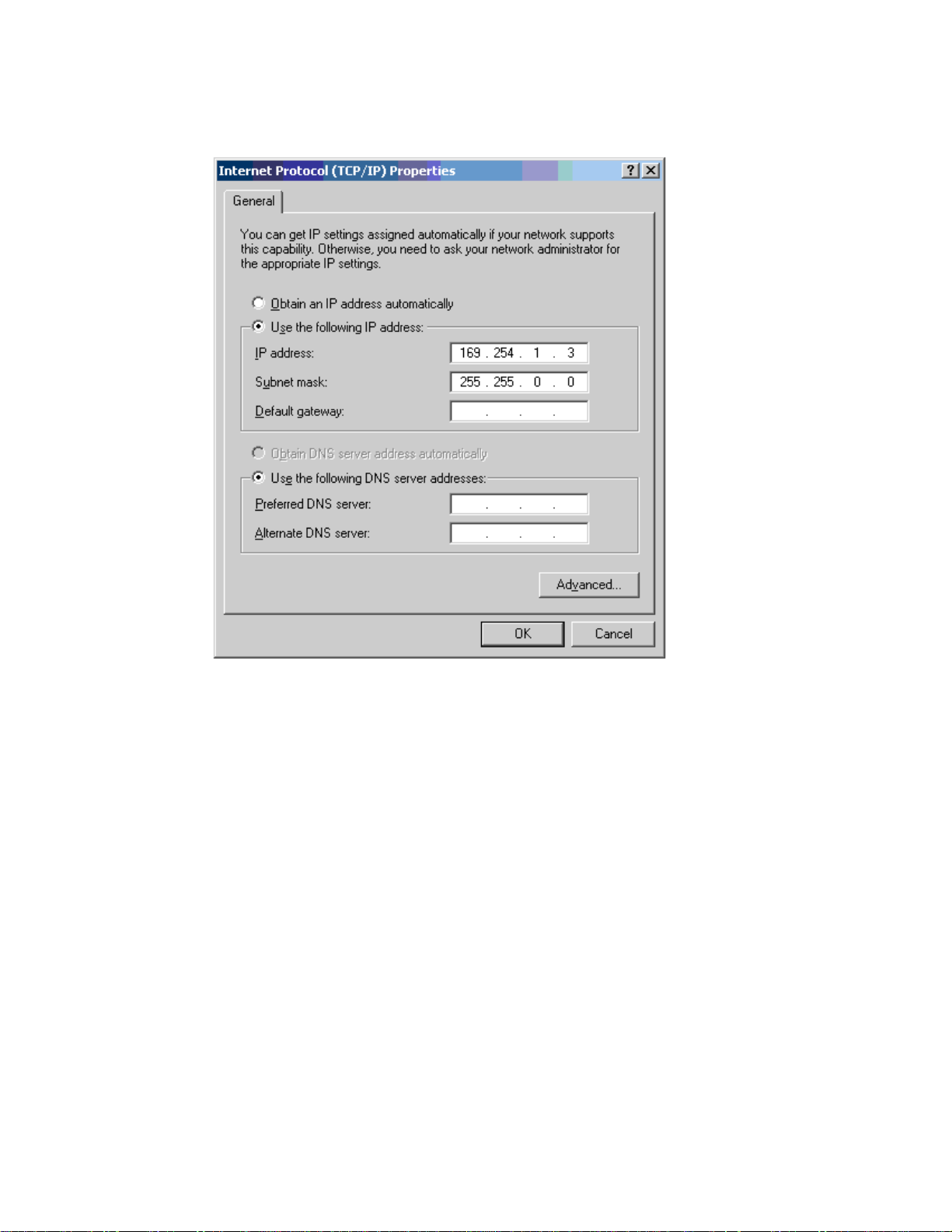
Select Properties for the Ethernet port. In Windows 7 this is found in Control Panel
> Network and Internet > Network Connections > Local Area Connection.
2
Select Internet Protocol (TCP/IP):
3
Click Properties.
Connecting to the unit
This section describes how to connect the unit to a management PC and power it up.
Configuring the management PC
Use this procedure to configure the local management PC to communicate with the PMP/PTP 450
platform.
Procedure 9 Configuring the management PC
Page 7-73
Chapter 7: Configuration
Connecting to the unit
4
Enter an IP address that is valid for the 169.254.X.X network, avoiding 169.254.0.0
and 169.254.1.1. A good example is 169.254.1.3:
5
Enter a subnet mask of 255.255.0.0. Leave the default gateway blank.
1
Check that the ODU and PSU are correctly connected.
2
Connect the PC Ethernet port to the LAN port of the PSU using a standard (not
crossed) Ethernet cable.
3
Apply mains or battery power to the PSU. The green Power LED should illuminate
continuously.
4
After about several seconds, check that the orange Ethernet LED starts with 10 slow
flashes.
5
Check that the Ethernet LED then illuminates continuously.
Connecting to the PC and powering up
Use this procedure to connect a management PC and power up the PMP/PTP 450 platform.
Procedure 10 Connecting to the PC and powering up
Page 7-74
Chapter 7: Configuration
Using the web interface
1
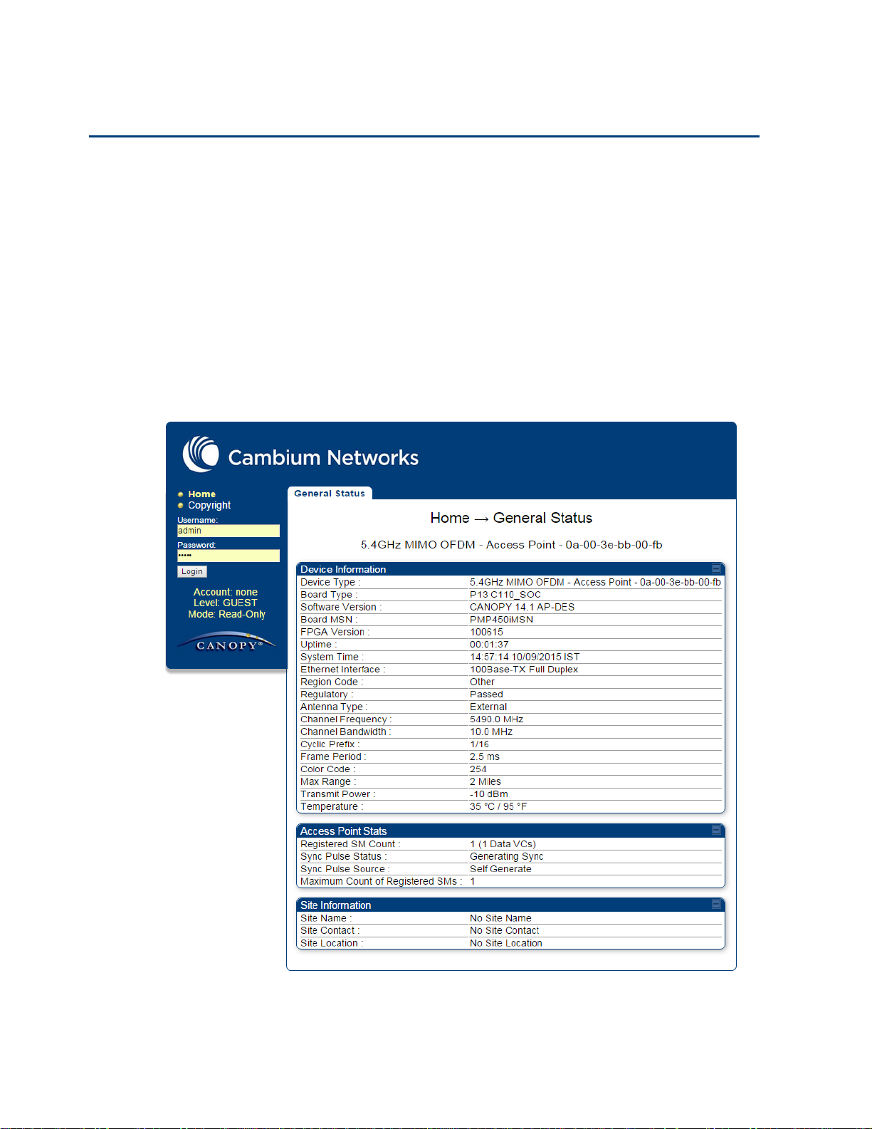
Start the web browser from the management PC.
2
Type the IP address of the unit into the address bar. The factory default IP address is
169.254.1.1. Press ENTER. The web interface menu and System Summary page are
displayed:
Using the web interface
This section describes how to log into the PMP/PTP 450 platform web interface and use its menus.
Logging into the web interface
Use this procedure to log into the web interface as a system administrator.
Procedure 11 Logging into the web interface
Page 7-75
Chapter 7: Configuration
Using the web interface
3
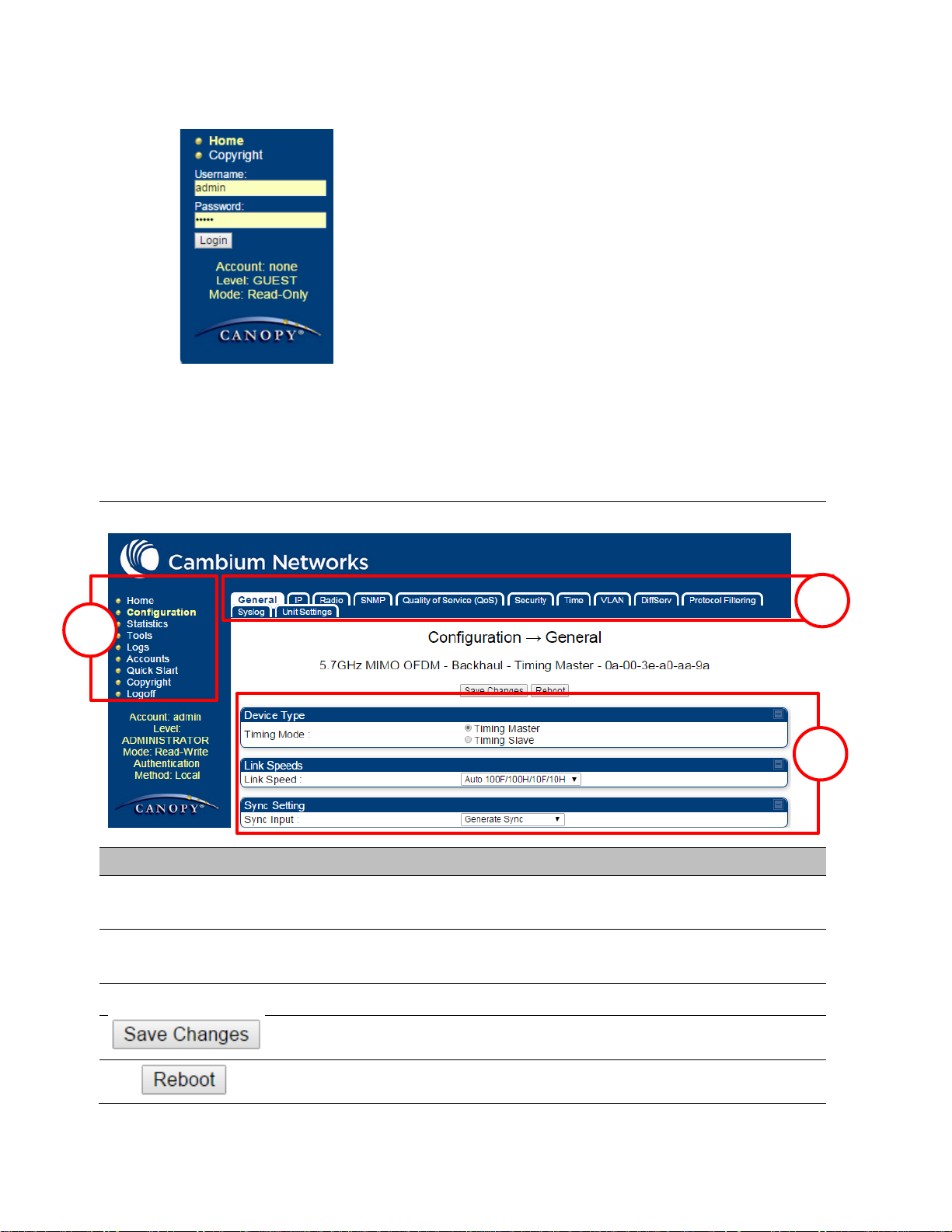
On left hand side of home page, the login information is displayed:
4
Enter Username (factory default username is admin) and Password (factory default password
is admin) and click Login.
Field Name
Description
Main Manu
Click an option in side navigation bar (area marked as “1”). Multiple
options in sub-navigation bars appear
Menu Option
Click top sub-navigation bar to choose one configuration page (area
marked as “2”)
Parameter
To configure the parameters (e.g. area marked as “3”)
Press "Save Changes" to confirm and save the changes
To reboot the ODU
1
2
3
Web GUI
1
Page 7-76
Chapter 7: Configuration
Using the web interface
Main
menu
Menu options
Applicable
module
Description
All
Viewing General Status on page 9-2
AP, BHM
Viewing Session Status on page 9-16
All
Interpreting messages in the Event
Log on page 9-23
AP, BHM
Viewing the Network Interface on
page 9-25
All
Viewing the Layer 2 Neighbors on
page 9-26
All
General configuration on page 7-139
All
Configuring IP and Ethernet interfaces
on page 7-92
All
Configuring radio parameters on page
7-193
All
Setting up SNMP agent on page 7-242
All
Configuring quality of service on page
7-259
All
Configuring security on page 7-165
AP, BHM
Setting up time and date
Time page of PMP/PTP 450 platform
AP/BHM on page 7-161
All
VLAN configuration for PMP on page
7-114
VLAN configuration for PTP on page
7-124
Event Log
Network Interface
General
IP
Radio
SNMP
Qaulity of Service (QoS)
Security
Time
VLAN
Layer 2 Neighbors
Session Status
General Status
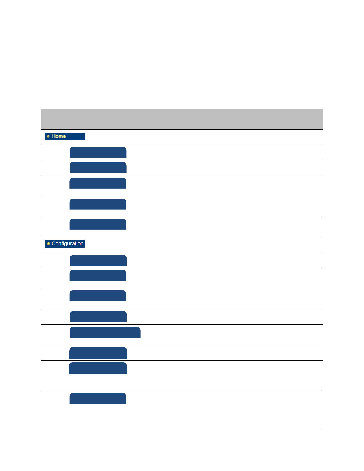
Using the menu options
Use the menu navigation bar in the left panel to navigate to each web page. Some of the menu
options are only displayed for specific system configurations. Use Table 83 to locate information
about using each web page.
Table 83 Menu options and web pages
Page 7-77
Chapter 7: Configuration
Using the web interface
Main
menu
Menu options
Applicable
module
Description
All
IPv4 and IPv6 Prioritization on page 7131
All
Filtering protocols and ports on page
7-132
All
Configuring syslog on page 7-249
All
Configuring Unit Settings page on
page 7-157
All
Viewing the Scheduler statistics on
page 9-27
AP, BHM
Viewing list of Registration Failures
statistics on page 9-29
All
Interpreting Bridge Control Block
statistics on page 9-52
All
Interpreting Bridging Table statistics
on page 9-30
All
Interpreting Ethernet statistics on
page 9-32
All
Interpreting RF Control Block statistics
on page 9-35
All
Interpreting VLAN statistics on page
9-36
All
Interpreting Data VC statistics on page
9-38
AP, BHM
Interpreting Throughput statistics on
page 9-40
SM
Interpreting Filter statistics on page 946
SM
Viewing ARP statistics on page 9-47
All
Interpreting Overload statistics on
page 9-43
All
Interpreting syslog statistics on page
9-57
SM
Interpreting Translation Table
statistics on page 9-31
DiffServ
Protocol Filtering
Syslog
Unit Setting
Scheduler
Registration Failures
Bridge Control Block
Bridging Table
Ethernet
Radio
VLAN
Data VC
Throughput
Filter
ARP
Overload
Syslog Statistics
Translation Table
Page 7-78

Chapter 7: Configuration
Using the web interface
Main
menu
Menu options
Applicable
module
Description
SM
Interpreting DHCP Relay statistics on
page 9-44
SM
Viewing NAT statistics on page 9-47
SM
Viewing NAT DHCP Statistics on page
9-49
AP
Interpreting Pass Through Statistics
on page 9-54
AP
Interpreting Sync Status statistics on
page 9-50
SM
Interpreting PPPoE Statistics for
Customer Activities on page 9-51
All
Interpreting SNMPv3 Statistics on
page 9-55
Interpreting SNMPv3 Statistics on
page 9-55
All
Using the Link Capacity Test tool on
page 8-21
All
Spectrum Analyzer tool on page 8-3
All
Remote Spectrum Analyzer tool on
page 8-12
SM, BHS
Using AP Evaluation tool on page 8-27
Using BHM Evaluation tool on page 8-
31
AP
Using the Subscriber Configuration
tool on page 8-39
AP, BHM
Using the OFDM Frame Calculator
tool on page 8-35
SM
Using BER Results tool on page 8-45
SM, BHS
Using the Alignment Tool on page 815
AP
Using the Link Status tool on page 840
AP
Using the Sessions tool on page 8-46
Link Capacity Test
Spectrum Analyzer
Remote Spectrum Analyzer
OFDM Frame Calculator
Link Status
Sessions
AP/BHM Evaluation
BER results
DHCP Relay
NAT Stats
NAT DHCP
Sync Status
PPPoE
SNMPv3 Statistics
Pass Through Statistics
Frame Utilization
Alignment Tool
Subscriber Configuration
Page 7-79
Chapter 7: Configuration
Using the web interface
Main
menu
Menu options
Applicable
module
Description
Changing a User Setting on page 7167
Adding a User for Access to a module
on page 7-166
Deleting a User from Access to a
module on page 7-167
Users account on page 7-168
AP, BHM
Quick link setup on page 7-81
AP, BHM
Quick link setup on page 7-81
AP, BHM
Quick link setup on page 7-81
AP, BHM
Quick link setup on page 7-81
AP, BHM
Quick link setup on page 7-81
AP, BHM
Quick link setup on page 7-81
SM
The PDA web-page includes 320 x 240
pixel formatted displays of
information important to installation
and alignment for installers using
legacy PDA devices. All device web
pages are compatible with touch
devices such as smart phones and
tablets.
SM
SM
SM
SM
All
The Copyright web-page displays
pertinent device copyright
information.
All
Change User Setting
Add user
Delete User
User
Copyright Notices
Quick Start
Synchronization
LAN IP Address
Region Settings
Radio Carrier Frequency
Review and Save Configuration
Quick Status
Spectrum Results (PDA)
Information
BHM Evaluation
AIM
Page 7-80
Chapter 7: Configuration
Quick link setup
Note
If the IP address of the AP or BHM is not known, See Radio recovery mode on page 1-
22.
Applicable products
PMP :
AP
PTP:
BHM
Quick link setup
This section describes how to use the Quick Start Wizard to complete the essential system
configuration tasks that must be performed on a PMP/PTP configuration.
Initiating Quick Start Wizard
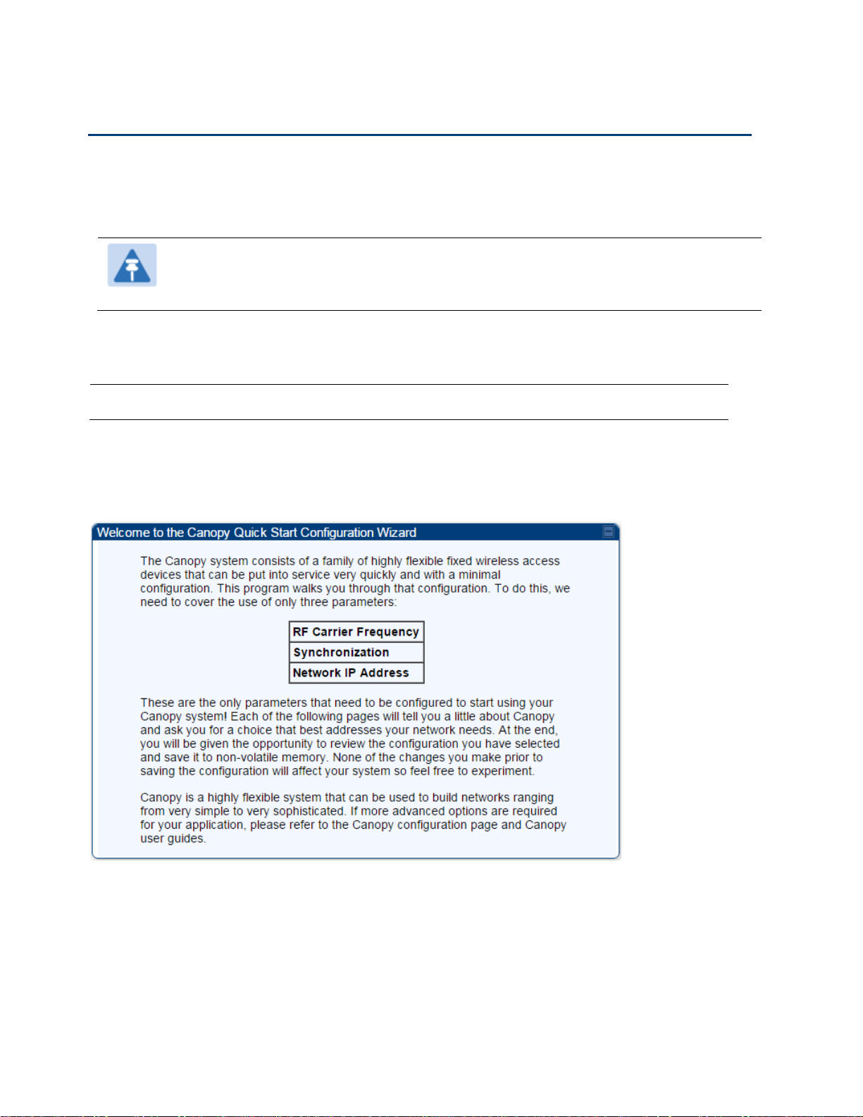
To start with Quick Start Wizard: after logging into the web management interface click the Quick
Start button on the left side of main menu bar. The AP/BHM responds by opening the Quick Start
page.
Figure 99 Disarm Installation page (top and bottom of page shown)
Quick Start is a wizard that helps you to perform a basic configuration that places an AP/BHM into
service. Only the following parameters must be configured:
Region Code
RF Carrier Frequency
Synchronization
LAN (Network) IP Address
Page 7-81
Chapter 7: Configuration
Quick link setup
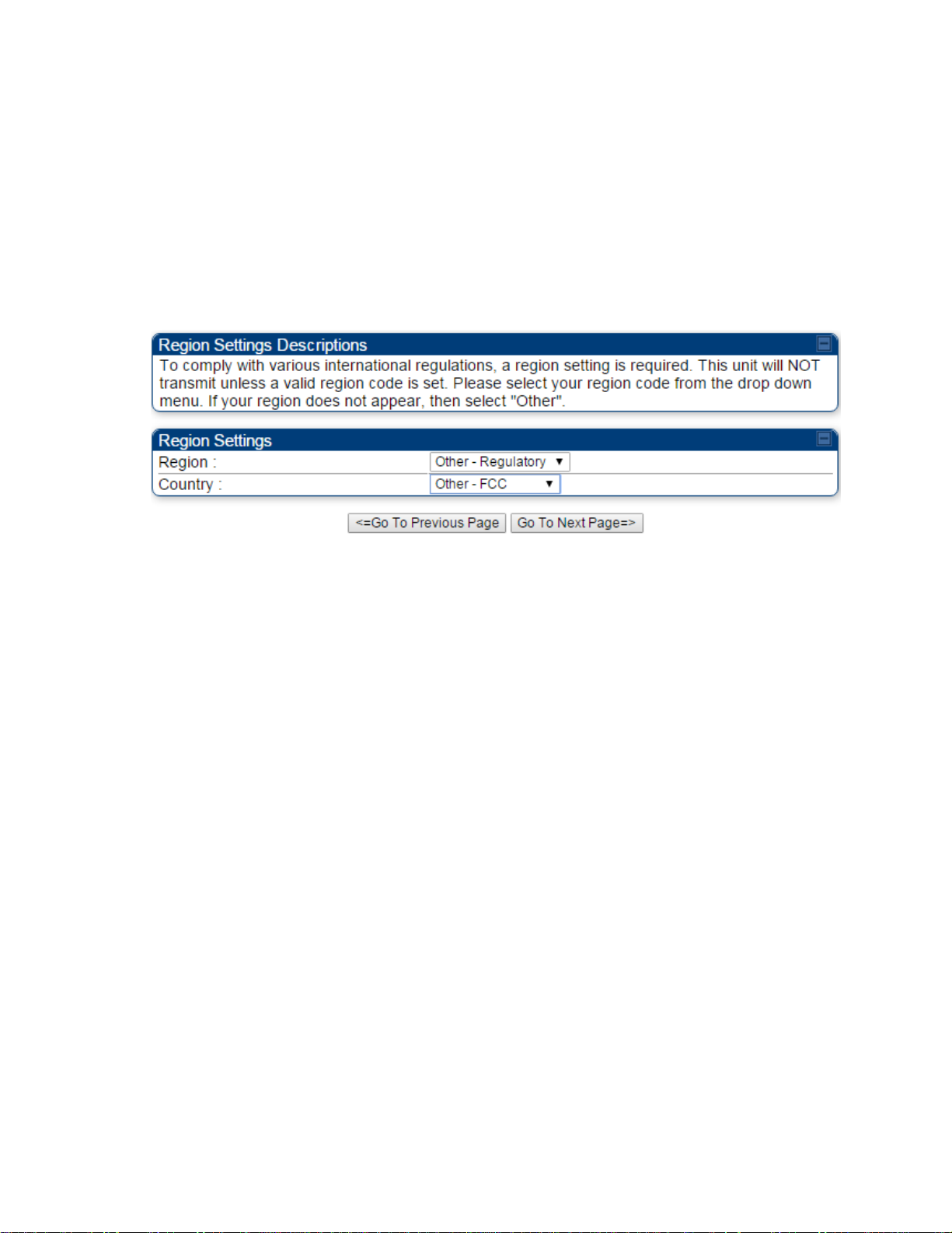
1
At the bottom of the Quick Start tab, click the Go To Next Page button.
2
From the pull-down menu, select the region in which the AP will operate.
Figure 100 Regional Settings tab of AP/BHM
3
Click the Go To Next Page button.
In each Quick Start page, you can
specify the settings to satisfy the requirements of the network.
review the configuration selected.
save the configuration to non-volatile memory.
Procedure 12 Quick start wizard
Page 7-82
Chapter 7: Configuration
Quick link setup
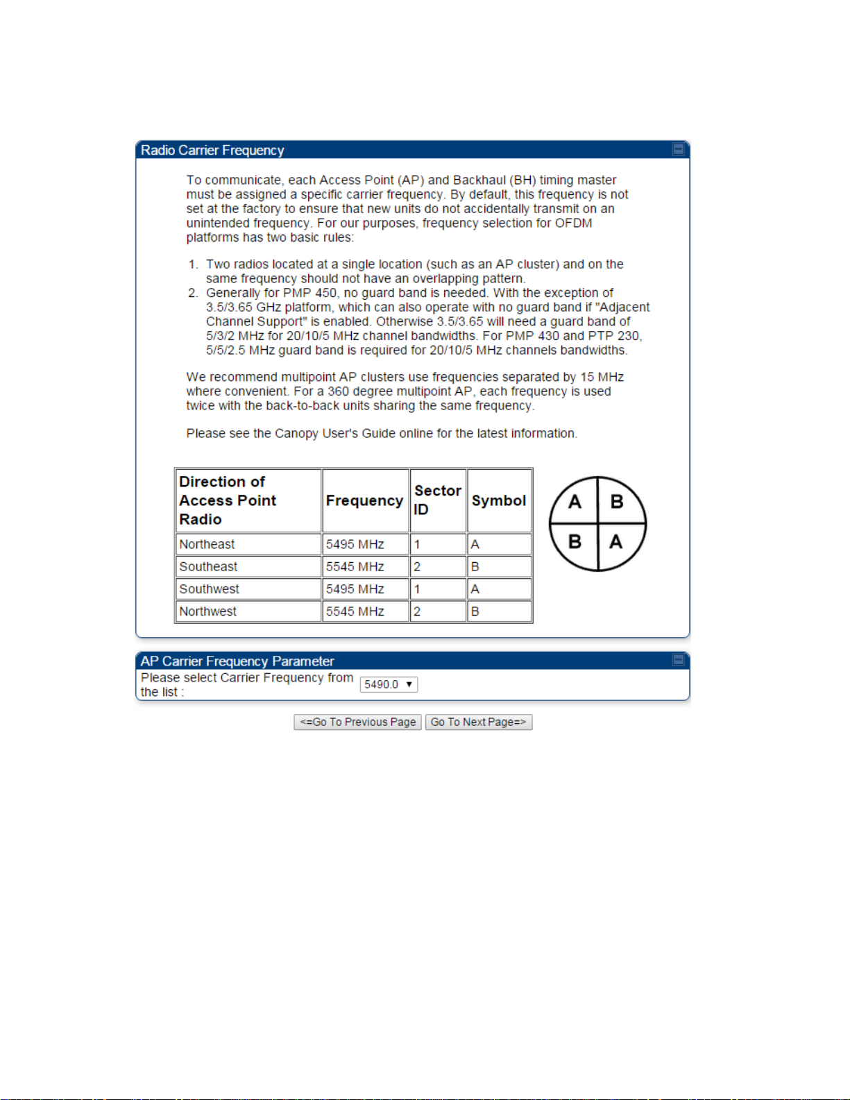
4
From the pull-down menu, select a frequency for the test.
Figure 101 Radio Carrier Frequency tab of AP/BHM
5
Click the Go To Next Page button.
Page 7-83
Chapter 7: Configuration
Quick link setup
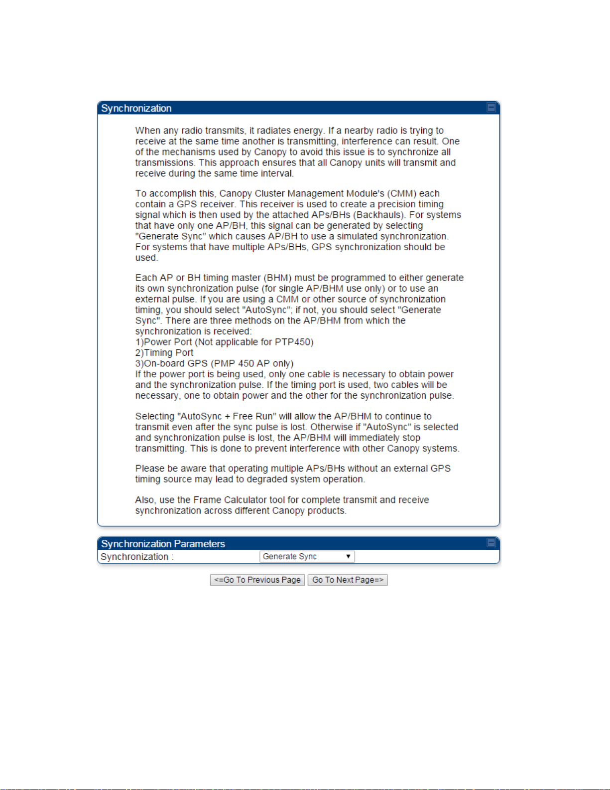
6
At the bottom of this tab, select Generate Sync Signal.
Figure 102 Synchronization tab of AP/BHM
7
Click the Go To Next Page button.
Page 7-84
Chapter 7: Configuration
Quick link setup
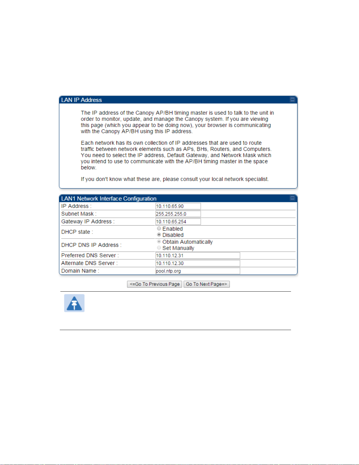
8
At the bottom of the IP address configuration tab, either
specify an IP Address, a Subnet Mask, and a Gateway IP Address for management of the
AP and leave the DHCP state set to Disabled.
set the DHCP state to Enabled to have the IP address, subnet mask, and gateway IP
address automatically configured by a domain name server (DNS).
Figure 103 LAN IP Address tab of the AP/BHM
Note
Cambium encourages you to experiment with the interface. Unless you
save a configuration and reboot the AP after you save the configuration,
none of the changes are affected.
9
Click the Go To Next Page => button.
Page 7-85
Chapter 7: Configuration
Quick link setup
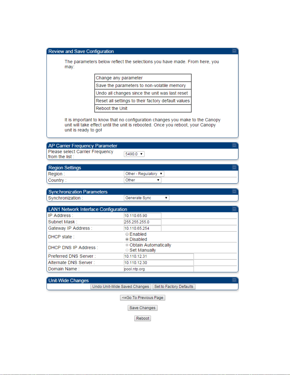
10
Ensure that the initial parameters for the AP are set as you intended.
Figure 104 Review and Save Configuration tab of the AP/BHM
11
Click the Save Changes button.
12
Click the Reboot button.
RESULT: The AP responds with the message Reboot Has Been Initiated…
Page 7-86

Chapter 7: Configuration
Quick link setup
13
Wait until the indicator LEDs are not red.
14
Trigger your browser to refresh the page until the AP redisplays the General Status tab.
15
Wait until the red indicator LEDs are not lit.
Applicable products
PMP :
AP
PTP:
BHM
Configuring time settings
To proceed with the test setup, click the Configuration link on the left side of the General Status
page. When the AP responds by opening the Configuration page to the General page, click the
Time tab.
Figure 105 Time tab of the AP/BHM
To have each log in the AP/BHM correlated to a meaningful time and date, either a reliable network
element must pass time and date to the AP/BHM or you must set the time and date whenever a
power cycle of the AP/BHM has occurred. A network element passes time and date in any of the
following scenarios:
A connected CMM4 passes time and date (GPS time and date, if received).
A separate NTP server is addressable from the AP/BHM.
If the AP/BHM should obtain time and date from a CMM4, or a separate NTP server, enter the IP
address of the CMM4 or NTP server on this tab. To force the AP/BHM to obtain time and date
before the first (or next) 15-minute interval query of the NTP server, click Get Time through NTP.
Page 7-87
Chapter 7: Configuration
Quick link setup
Time :
hh
/
mm
/
ss
Date :
MM / dd / yyyy
hh
represents the two-digit hour in the range 00 to 24
mm
represents the two-digit minute
ss
represents the two-digit second
MM
represents the two-digit month
dd
represents the two-digit day
yyyy
represents the four-digit year
1
Enter the appropriate information in the format shown above.
2
Then click the Set Time and Date button.
Note
The time displayed at the top of this page is static unless your browser
is set to automatically refresh
1
In one hand, securely hold the top (larger shell) of the SM/BHS. With the other hand,
depress the lever in the back of the base cover (smaller shell). Remove the base
cover.
2
Plug one end of a CAT 5 Ethernet cable into the SM PSU port
3
Plug the other end of the Ethernet cable into the jack in the pig tail that hangs from
the power supply
4
Roughly aim the SM/BHS toward the AP/BHM
5
Plug the power supply into an electrical outlet
Warning
From this point until you remove power from the AP/BHM, stay at
least as far from the AP/BHM as the minimum separation distance
specified in Calculated distances and power compliance margins.
6
Repeat the foregoing steps for each SM/BHS that you wish to include in the test.
If you enter a time and date, the format for entry is
Figure 106 Time and date entry formats
where
Proceed with the time setup as follows.
Procedure 13 Entering AP/BHM time setup information
Powering the SM/BHS for test
Procedure 14 Powering the SM/BHS for test
Page 7-88

Chapter 7: Configuration
Quick link setup
Note
In order for accurate power level readings to be displayed, traffic must be present on
the radio link.
Viewing the Session Status of the AP/BHM to determine test registration
Once the SMs/BHS under test are powered on, return to the computing device to determine if the
SM/BHS units have registered to the AP/BHM.
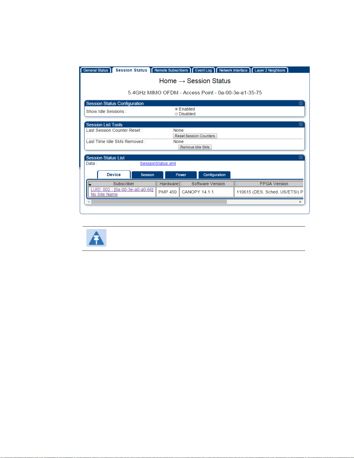
The Session Status tab provides information about each SM/BHS that has registered to
the AP/BHM. This information is useful for managing and troubleshooting a system.
All information that you have entered in the Site Name field of the SM/BHS displays in the Session
Status tab of the linked AP/BHM.
The Session Status tab also includes the current active values on each SM( or BHS) (LUID) for MIR,
and VLAN, as well as the source of these values (representing the SM/BHS itself, Authentication
Server, or the AP/BHM and cap, if any—for example, APCAP as shown above).. As an SM/BHS
registers to the AP/BHM, the configuration source that this page displays for the associated LUID
may change. After registration, however, the displayed source is stable and can be trusted.
Idle subscribers may be included or removed from the session status display by enabling or
disabling, respectively, the Show Idle Sessions parameter. Enabling or disabling this parameter
only affects the GUI display of subscribers, not the registration status.
The SessionStatus.xml hyperlink allows user to export session status page from web management
interface of AP/BHM. The session status page will be exported in xml file.
Page 7-89
Chapter 7: Configuration
Quick link setup
1
On the AP web management GUI, navigate to Home, Session Status:
Figure 107 Session Status tab of AP
Note
Session status page for BHM is same as AP.
2
Verify that for each SM (or BHS) MAC address (printed on the SM/BHS housing) the
AP/BHM has established a registered session by verifying the “State” status of each
entry.
Procedure 15 Viewing the AP Session Status page
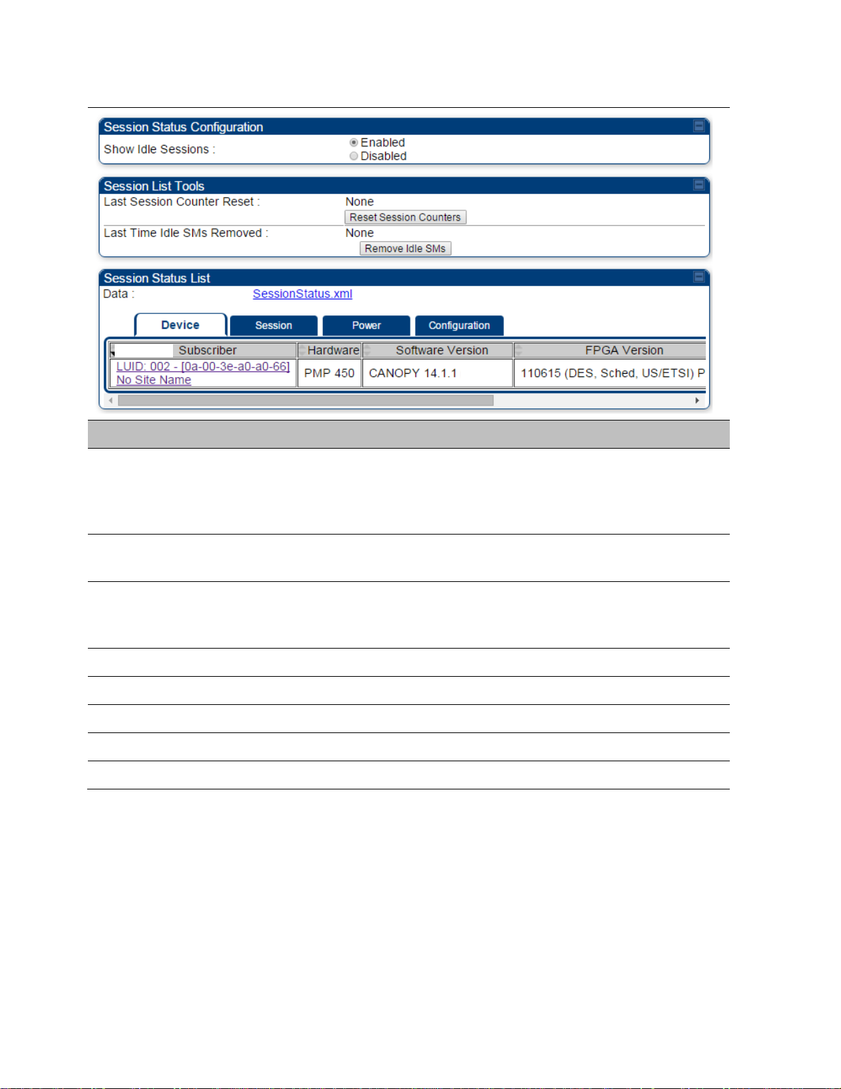
The Session Status page of the AP/BHM is explained in Table 84.
Page 7-90
Chapter 7: Configuration
Quick link setup
Attribute
Meaning
Show Idle Sessions
Idle subscribers may be included or removed from the session status
display by enabling or disabling, respectively, the Show Idle Sessions
parameter. Enabling or disabling this parameter only affects the GUI
display of subscribers, not the registration status.
Last Session Counter
Reset
This field displays date and time stamp of last session counter reset.
Last Time Idle SMs
Removed
This field displays date and time stamp of last Idle SMs Removed. On
click of “Remove Idle SMs” button, all the SMs which are in Idle state
are flushed out.
Data
See Exporting Session Status page of AP/BHM on page 7-270
Device tab
See Device tab on page 9-16
Session tab
See Session tab on page 9-17
Power tab
See Power tab on page 9-19
Configuration tab
See Configuration tab on page 9-20
Table 84 Session Status Attributes – AP
Page 7-91

Chapter 7: Configuration
Configuring IP and Ethernet interfaces
Configuring IP and Ethernet interfaces
This task consists of the following sections:
Configuring the IP interface on page 7-93
Auxiliary port on page 7-96
NAT, DHCP Server, DHCP Client and DMZ on page 7-97
IP interface with NAT disabled on page 7-102
IP interface with NAT enabled on page
NAT tab with NAT disabled on page 7-105
NAT tab with NAT enabled on page 7-108
NAT DNS Considerations on page 7-113
DHCP – BHS on page 7-114
VLAN configuration for PMP on page 7-114
VLAN page of AP on page 7-117
VLAN page of SM on page 7-120
VLAN Membership tab of SM on page 7-124
VLAN configuration for PTP on page 7-124
NAT Port Mapping tab - SM on page 7-113
Page 7-92
Chapter 7: Configuration
Configuring IP and Ethernet interfaces
Applicable products
PMP :
AP SM
PTP:
BHM
BMS
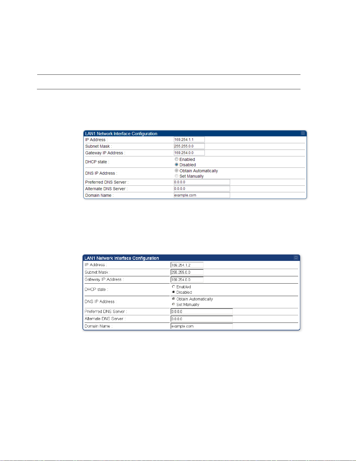
1
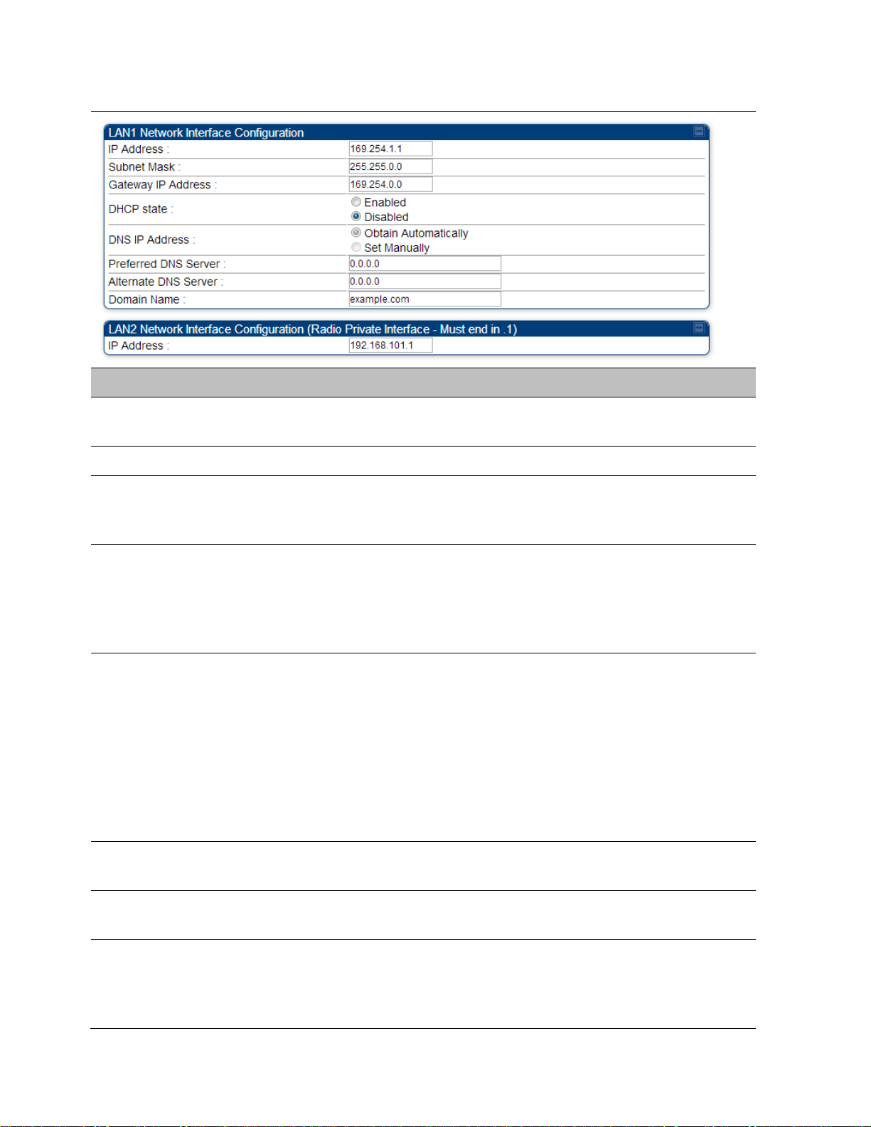
Select menu option Configuration > IP. The LAN configuration page is displayed:
2
Update IP Address, Subnet Mask and Gateway IP Address to meet network
requirements (as specified by the network administrator).
3
Review the other IP interface attributes and update them, if necessary (see Table 85 IP
interface attributes).
4
Click Save. “Reboot Required” message is displayed:
5
Click Reboot.
Configuring the IP interface
The IP interface allows users to connect to the PMP/PTP 450 platform web interface, either from a
locally connected computer or from a management network.
To configure the IP interface, follow these instructions:
Procedure 16 Configuring the AP/BHM IP interface
The IP page of AP/SM/BHM/BHS is explained in Table 85.
Page 7-93
Chapter 7: Configuration
Configuring IP and Ethernet interfaces
Attribute
Meaning
IP Address
Internet Protocol (IP) address. This address is used by family of Internet
protocols to uniquely identify this unit on a network.
Subnet Mask
Defines the address range of the connected IP network.
The IP address of a computer on the current network that acts as a
gateway. A gateway acts as an entrance and exit to packets from and to
other networks.
DHCP state
If Enabled is selected, the DHCP server automatically assigns the IP
configuration (IP address, subnet mask, and gateway IP address) and the
values of those individual parameters (above) are not used. The setting
of this DHCP state parameter is also viewable (read only), in the Network
Interface tab of the Home page.
DNS IP Address
Canopy devices allow for configuration of a preferred and alternate DNS
server IP address either automatically or manually. Devices must set
DNS server IP address manually when DHCP is disabled for the
management interface of the device. DNS servers may be configured
automatically from the DHCP response when DHCP is enabled for the
management interface of the device. Optionally devices may be
configured to set the DNS server IP address manually when DHCP is
enabled for the management interface. The default DNS IP addresses are
0.0.0.0 when configured manually.
Preferred DNS
Server
The first address used for DNS resolution.
Alternate DNS
Server
If the Preferred DNS server cannot be reached, the Alternate DNS Server
is used.
Domain Name
The operator’s management domain name may be configured for DNS.
The domain name configuration can be used for configuration of the
servers in the operator’s network. The default domain name is
example.com, and is only used if configured as such.
Table 85 IP interface attributes
Page 7-94

Chapter 7: Configuration
Configuring IP and Ethernet interfaces
LAN2 Network
Interface
Configuration (Radio
Private Interface) – IP
Address
It is recommended not to change this parameter from the default
AP/BHM private IP address of 192.168.101.1. A /24 CIDR subnet is used to
communicate with each of the SMs/BHS that are registered. The AP/BHM
uses a combination of the private IP and the LUID (logical unit ID) of the
SM/BHS.
It is only displayed for AP and BHM.
Table 86 SM/BHS private IP and LUID
SM/BHS
LUID
Private IP
First SM/BHS registered
2
192.168.101.2
Second SM/BHS registered
3
192.168.101.3
Page 7-95
Chapter 7: Configuration
Configuring IP and Ethernet interfaces
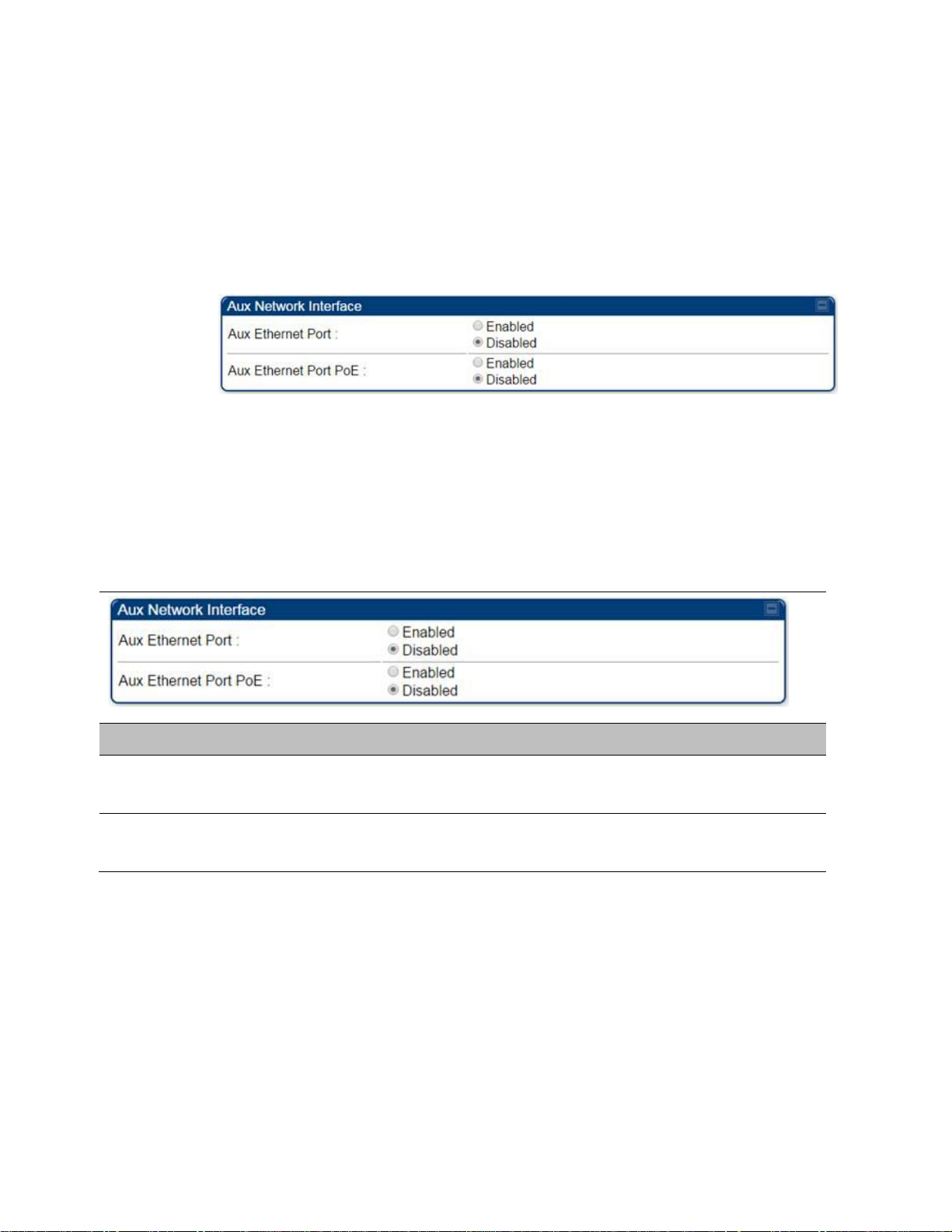
1
Select menu option Configuration > IP > Aux Network Interface tab.:
2
Click Enable button of Aux Ethernet Port parameter to enable Aux Ethernet port
3
Click Enable button of Aux Ethernet Port PoE parameter to enable Aux port PoE out.
4
Click Save. “Reboot Required” message is displayed.
5
Click Reboot.
Attribute
Meaning
Aux Ethernet Port
Enabled: Data is enabled for Auxiliary port
Disabled: Data is disabled for Auxiliary port
Aux Ethernet Port
PoE
Enabled: PoE out is enable for Auxiliary port
Disabled: PoE out is disabled for Auxiliary port
Auxiliary port
An additional Ethernet port labeled “Aux” for Auxiliary port is implemented for downstream
traffic. This feature is supported only for PTP/PMP 450i series devices.
To enable the Aux port, follow these instructions:
Procedure 17 Enabling Aux port interface
Table 87 Aux port attributs
By disabling this feature, the data at the Auxiliary port will be disabled.
Page 7-96

Chapter 7: Configuration
Configuring IP and Ethernet interfaces
Applicable products
PMP :
SM
Note
When NAT is enabled, a reduction in throughput is introduced in the system (due to
processing overhead).
NAT, DHCP Server, DHCP Client and DMZ
The system provides NAT (Network Address Translation) for SMs in the following combinations of
NAT and DHCP (Dynamic Host Configuration Protocol):
NAT Disabled
NAT with DHCP Client (DHCP selected as the Connection Type of the WAN interface) and DHCP
Server
NAT with DHCP Client(DHCP selected as the Connection Type of the WAN interface)
NAT with DHCP Server
NAT without DHCP
NAT
NAT isolates devices connected to the Ethernet or wired side of a SM from being seen directly
from the wireless side of the SM. With NAT enabled, the SM has an IP address for transport traffic
(separate from its address for management), terminates transport traffic and allows you to assign
a range of IP addresses to devices that are connected to the Ethernet or wired side of the SM.
In the Cambium system, NAT supports many protocols, including HTTP, ICMP (Internet Control
Message Protocols), and FTP (File Transfer Protocol). For virtual private network (VPN)
implementation, L2TP over IPSec (Level 2 Tunneling Protocol over IP Security) and PPTP (Point to
Point Tunneling Protocol) are supported.
DHCP
DHCP enables a device to be assigned a new IP address and TCP/IP parameters, including a default
gateway, whenever the device reboots. Thus DHCP reduces configuration time, conserves IP
addresses, and allows modules to be moved to a different network within the Cambium system.
In conjunction with the NAT features, each SM provides the following:
A DHCP server that assigns IP addresses to computers connected to the SM by Ethernet
protocol.
A DHCP client that receives an IP address for the SM from a network DHCP server.
Page 7-97
Chapter 7: Configuration
Configuring IP and Ethernet interfaces
DMZ
In conjunction with the NAT features, a DMZ (Demilitarized Zone) allows the allotment of one IP
address behind the SM for a device to logically exist outside the firewall and receive network
traffic. The first three octets of this IP address must be identical to the first three octets of the NAT
private IP address.
A DHCP server that assigns IP addresses to computers connected to the SM by Ethernet
protocol.
A DHCP client that receives an IP address for the SM from a network DHCP server.
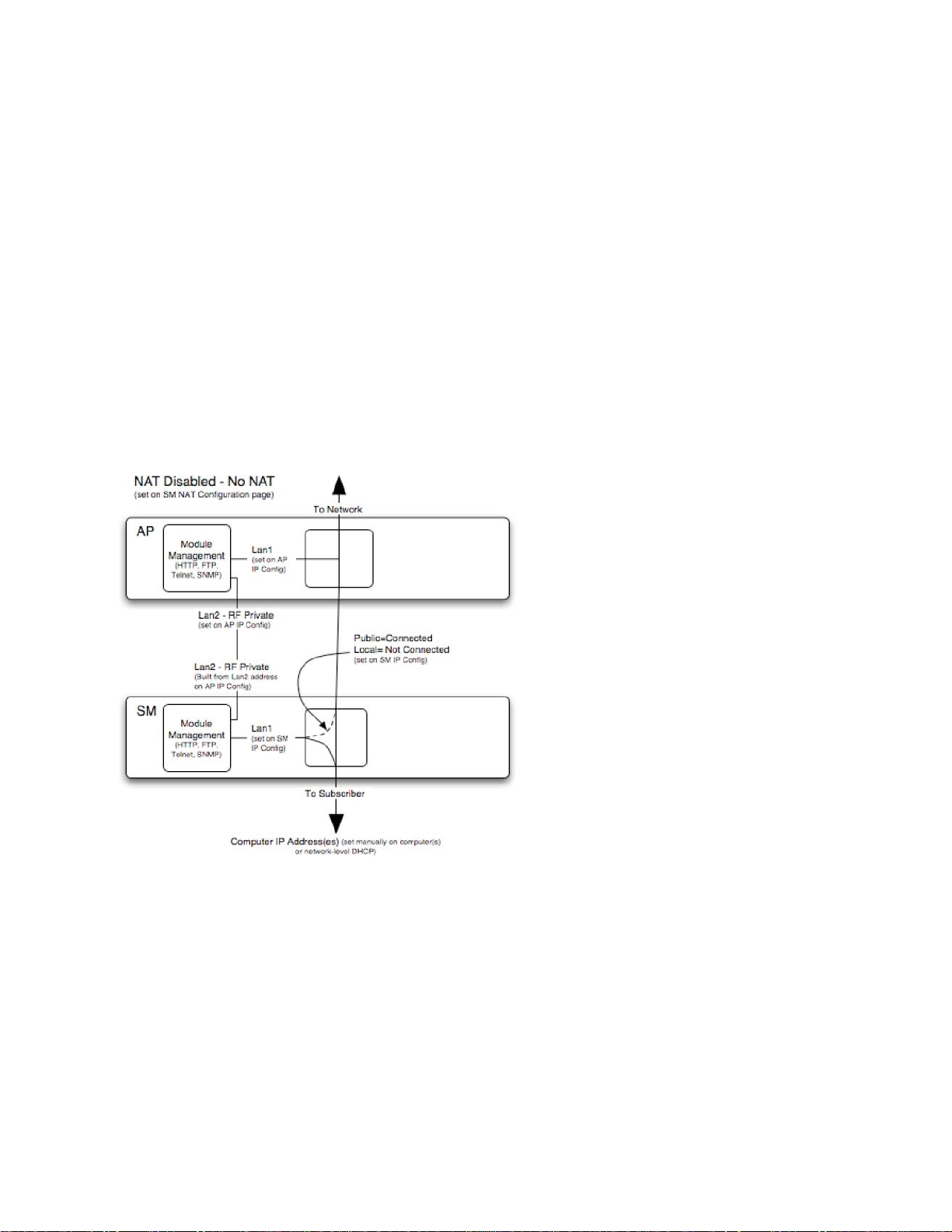
NAT Disabled
The NAT Disabled implementation is illustrated in Figure 108.
Figure 108 NAT disabled implementation
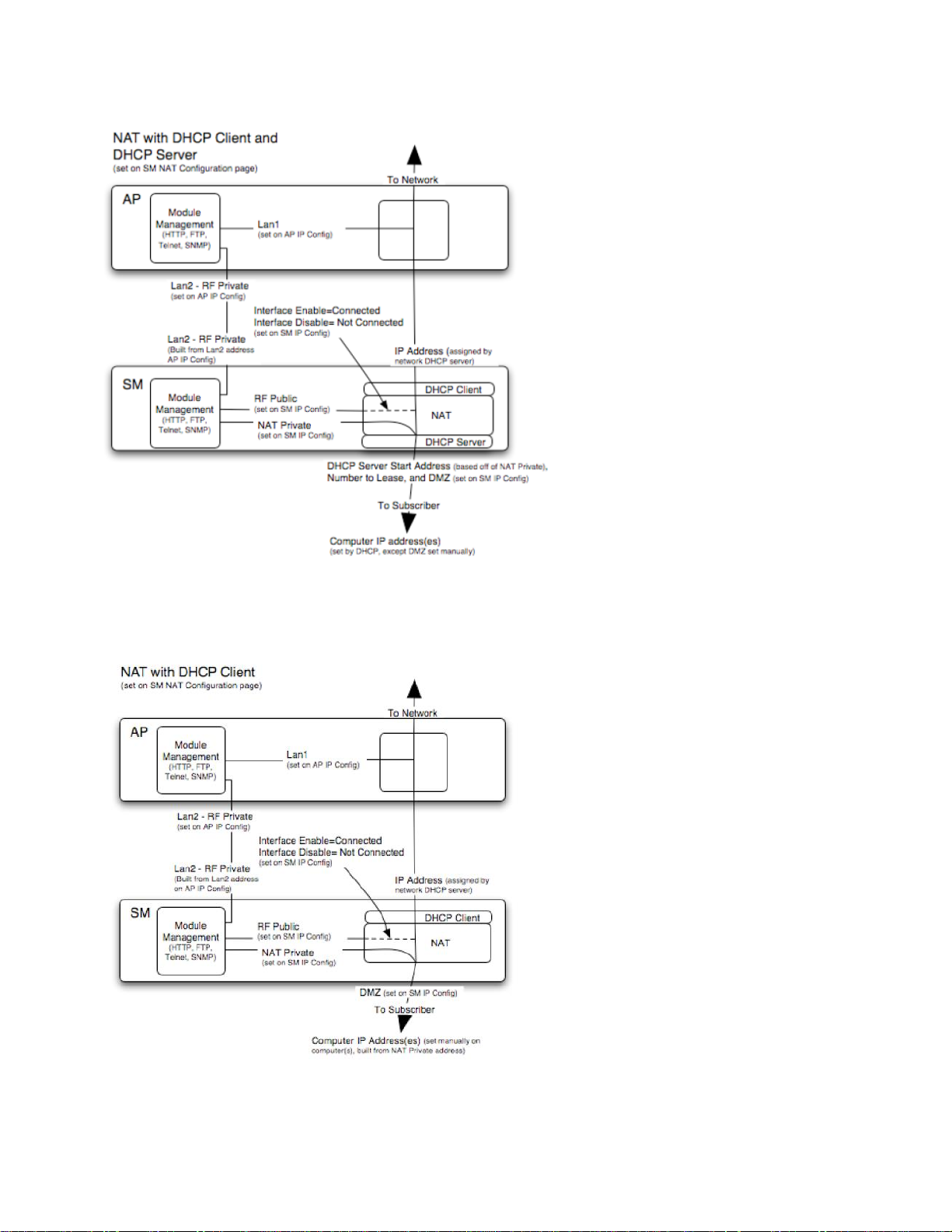
NAT with DHCP Client and DHCP Server
The NAT with DHCP Client and DHCP server is illustrated in Figure 109.
Page 7-98
Chapter 7: Configuration
Configuring IP and Ethernet interfaces
Figure 109 NAT with DHCP client and DHCP server implementation
NAT with DHCP Client
Figure 110 NAT with DHCP client implementation
Page 7-99
Chapter 7: Configuration
Configuring IP and Ethernet interfaces
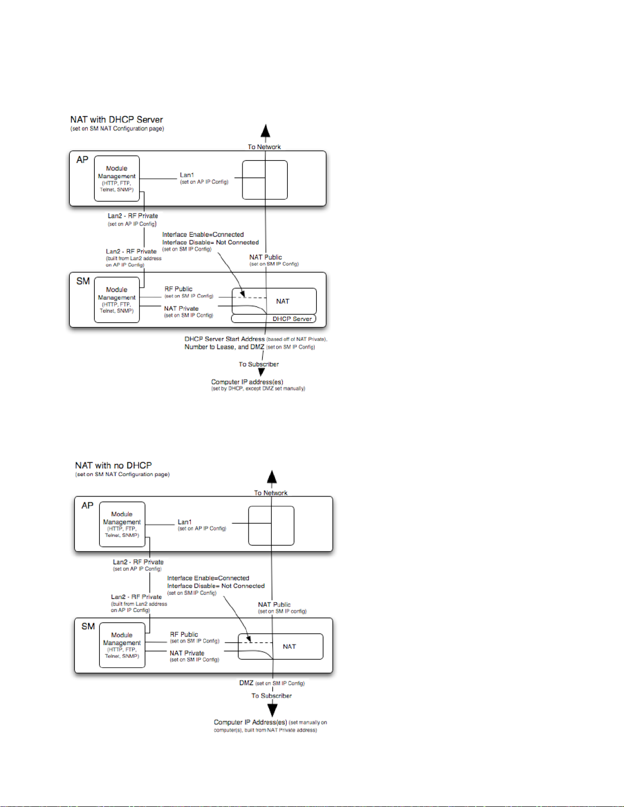
NAT with DHCP Server
Figure 111 NAT with DHCP server implementation
NAT without DHCP
Figure 112 NAT without DHCP implementation
Page 7-100
 Loading...