

Cambium Networks 50450I Users manual
Chapter 7: Configuration Configuring security
Attribute
Meaning
Port configuration
450 Platform Family ODUs support access to various communication protocols and only the ports
required for these protocols are available for access by external entities. Operators may change
the port numbers for these protocols via the radio GUI or SNMP.
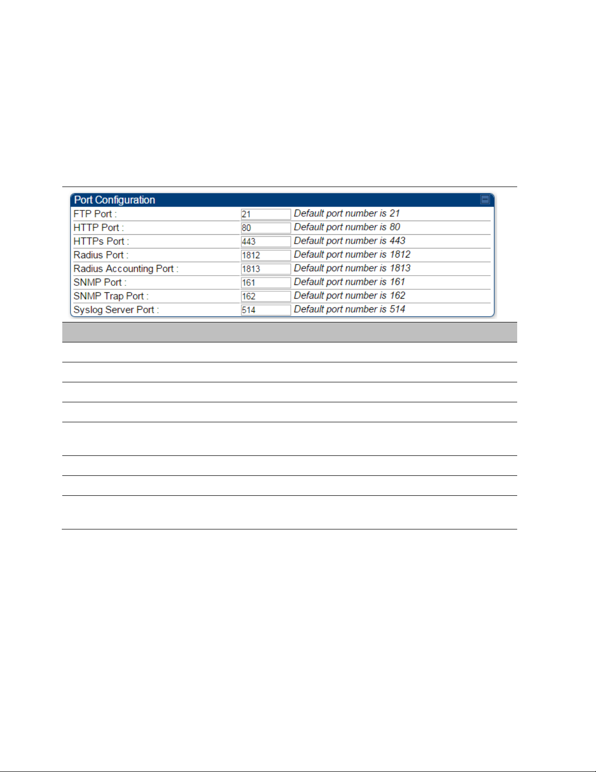
The Port Configuration page of the AP/SM/BHM/BHS is explained in Table 137.
Table 137 Port Configuration attributes – AP/SM/BHM/BMS
FTP Port The listen port on the device used for FTP communication.
HTTP Port The listen port on the device used for HTTP communication.
HTTPS Port The listen port on the device used for HTTPS communication
Radius Port The destination port used by the device for RADIUS communication.
Radius Accounting
Port
SNMP Port The listen port on the device used for SNMP communication.
SNMP Trap Port The destination port used by the device to which SNMP traps are sent.
Syslog Server Port
The destination port used by the device for RADIUS accounting
communication.
The destination port used by the device to which Syslog messaging is
sent.
Encrypting downlink broadcasts
See Encrypting downlink broadcasts on page 3-48.
Isolating SMs
See Isolating SMs in PMP on page 3-48.
Page 7-110

Chapter 7: Configuration Configuring security
Filtering management through Ethernet
See Filtering management through Ethernet on page 3-48.
Allowing management only from specified IP addresses
See Allowing management from only specified IP addresses on page 3-49.
Restricting radio Telnet access over the RF interface
RF Telnet Access restricts Telnet access to the AP from a device situated below a network SM
(downstream from the AP). This is a security enhancement to restrict RF-interface sourced AP
access specifically to the LAN1 IP address and LAN2 IP address (Radio Private Address, typically
192.168.101. [LUID]). This restriction disallows unauthorized users from running Telnet commands
on the AP that can change AP configuration or modifying network-critical components such as
routing and ARP tables.
The RF Telnet Access may be configured via the AP GUI or via SNMP commands, and RF Telnet
Access is set to “Enabled” by default. Once RF Telnet Access is set to “Disabled”, if there is a
Telnet session attempt to the AP originating from a device situated below the SM (or any
downstream device), the attempt is dropped. This also includes Telnet session attempts originated
from the SM’s management interface (if a user has initiated a Telnet session to a SM and attempts
to Telnet from the SM to the AP). In addition, if there are any active Telnet connections to the AP
originating from a device situated below the SM (or any downstream device), the connection is
dropped. This behavior must be considered if system administrators use Telnet downstream from
an AP (from a registered SM) to modify system parameters.
Setting RF Telnet Access to “Disabled” does not affect devices situated above the AP from
accessing the AP via Telnet, including servers running the CNUT (Canopy Network Updater tool)
application. Also, setting RF Telnet Access to “Disabled” does not affect any Telnet access into
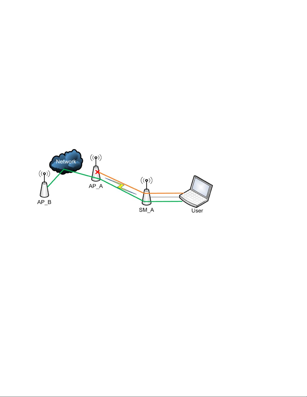
upstream devices (situated above or adjacent to the AP) through the AP (see Figure 143).
The figure below depicts a user attempting two telnet sessions. One is targeted for the AP (orange)
and one is targeted for the network upstream from the AP (green). If RF Telnet Access is set to
“Disabled” (factory default setting), the Telnet attempt from the user to the AP is blocked, but the
attempt from the user to Network is allowed to pass through the Cambium network.
Figure 143 RF Telnet Access Restrictions (orange) and Flow through (green)
Page 7-111
Chapter 7: Configuration Configuring security
1
2
Configuration > Protocol Filtering
Key Security Considerations when using the RF Telnet Access Feature
To ensure that the network is fully protected from unauthorized AP Telnet sessions, the following
topics must be considered:
Securing AP Clusters
When working with a cluster of AP units, to eliminate potential security holes allowing Telnet
access, ensure that the RF Telnet Access parameter is set to “Disabled” for every AP in the cluster.
In addition, since users situated below the AP are able to pass Telnet sessions up through the SM
and AP to the upstream network (while AP RF Telnet Access is set to “Disabled”), ensure that all
CMM4 or other networking equipment is secured with strong passwords. Otherwise, users may
Telnet to the CMM4 or other networking equipment, and subsequently access network APs (see
Figure 144) via their Ethernet interfaces (since RF Telnet Access only prevents Telnet sessions
originating from the AP’s wireless interface).
Figure 144 RF Telnet Access Restriction (orange) and Potential Security Hole (green)
As a common practice, AP administrator usernames and passwords must be secured with strong,
non-default passwords.
Restricting AP RF Telnet Access
AP Telnet access via the RF interface may be configured in two ways – the AP GUI and SNMP.
Controlling RF Telnet Access via the AP GUI
To restrict all Telnet access to the AP via the RF interface from downstream devices, follow these
instructions using the AP GUI:
Procedure 20 Restricting RF Telnet access
Log into the AP GUI using administrator credentials
On the AP GUI, navigate to
Page 7-112

Chapter 7: Configuration Configuring security
3
RF Telnet Access
Disabled
4
Save
5
Save
Note
Under GUI heading “Telnet Access over RF Interface”, set
Click the
button
Once the
below the AP is blocked.
The factory default setting for RF Telnet Access is disabled and PPPoE PADI
Downlink Forwarding is enabled.
to
button is clicked, all RF Telnet Access to the AP from devices situated
Page 7-113
Chapter 7: Configuration Configuring security
Note
1
2
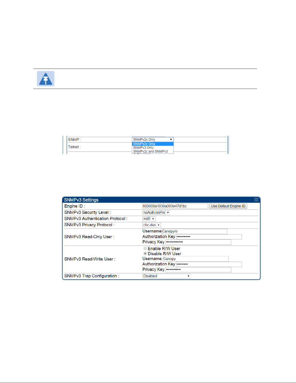
Configuration > Security Page
3
SNMP
SNMPv3 Only
4
Save Changes
5
Configuration > SNMP Page
6
Engine ID, SNMPv3 Security Level, SNMPv3
Authentication Protocol, SNMPv3 Privacy Protocol, SNMPv3 Read-Only User, SNMPv3
Read/Write User, SNMPv3 Trap Configuration
Engine ID :
SNMPv3 security level, Authentication and Privacy Protocol
Configuring SNMP Access
The SNMPv3 interface provides a more secure method to perform SNMP operations. This
standard provides services for authentication, data integrity and message encryption over SNMP.
Refer to Planning for SNMPv3 operation on page 3-42 for details.
The factory default setting for SNMP is “SNMPv2c Only”.
Procedure 21 Configuring SNMPv3
Log into the AP GUI using administrator credentials
On the AP/SM GUI, navigate to
Under GUI heading “Security Mode”, set
Click the
Go to
Under GUI heading “SNMPv3 setting”, set
button
to
parameters:
Each radio (AP/SM/BHM/BHS) has a distinct SNMP authoritative engine identified by a
unique Engine ID. While the Engine ID is configurable to the operator it is expected that
the operator follow the guidelines of the SNMPEngineID defined in the SNMPFRAMEWORK-MIB (RFC 3411). The default Engine ID is the MAC address of the device.
The authentication allows authentication of SNMPv3 user and privacy allows for
encryption of SNMPv3 message. 450 Platform Family supports MD5 authentication and
CBC-DES privacy protocols.
Page 7-114

Chapter 7: Configuration Configuring security
SNMPv3 Read-Only and Read/Write User
SNMPv3 Trap Configuration
The user can defined by configurable attributes. The attributes and default values are:
• Read-only user
o Username = Canopyro
o Authentication Password = authCanopyro
o Privacy Password = privacyCanopyro
• Read-write user (by default read-write user is disabled)
o Username = Canopy
o Authentication Password = authCanopy
o Privacy Password = privacyCanopy
The traps may be sent from radios in SNMPv3 format based on parameter settings. It
can be configured for Disabled, Enabled for Read-Only User, Enable for Read/Write
User.
Page 7-115
Chapter 7: Configuration Configuring security
Applicable products
PMP :
PTP:
Configuring Security
AP
SM
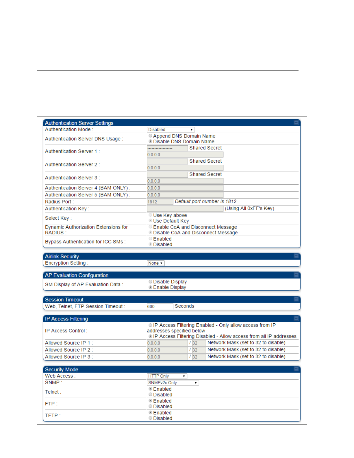
Security page – 450 Platform Family AP/BHM
The security page of AP/BHM is explained in Table 138.
Table 138 Security attributes –450 Platform Family AP
BHM
BMS
Page 7-116
Chapter 7: Configuration Configuring security
Attribute
Meaning
Disabled
Authentication Server
AP PreShared Key
RADIUS AAA
Note
Authentication Mode
Operators may use this field to select from among the following
authentication modes:
—the AP/BHM requires no SMs/BHS to authenticate. (Factory
default).
—the AP/BHM requires any SM/BHS that attempts
registration to be authenticated in Wireless Manager before registration.
- The AP/BHM acts as the authentication server to its
SMs/BHS and will make use of a user-configurable pre-shared
authentication key. The operator enters this key on both the AP/BHM and
all SMs/BHS desired to register to that AP/BHM. There is also an option
of leaving the AP/BHM and SMs/BHS at their default setting of using the
“Default Key”. Due to the nature of the authentication operation, if you
want to set a specific authentication key, then you MUST configure the
key on all of the SMs/BHS and reboot them BEFORE enabling the key
and option on the AP/BHM. Otherwise, if you configure the AP/BHM first,
none of the SMs/BHS is able to register.
- When RADIUS AAA is selected, up to 3 Authentication
Server (RADIUS Server) IP addresses and Shared Secrets can be
configured. The IP address(s) configured here must match the IP
address(s) of the RADIUS server(s). The shared secret(s) configured
here must match the shared secret(s) configured in the RADIUS
server(s). Servers 2 and 3 are meant for backup and reliability, not for
splitting the database. If Server 1 doesn’t respond, Server 2 is tried, and
then server 3. If Server 1 rejects authentication, the SM is denied entry
to the network, and does not progress trying the other servers.
This parameter is applicable to BHM.
Page 7-117

Chapter 7: Configuration Configuring security
Note
Authentication Mode RADIUS AAA
Shared Secret
Shared Secret
Note
Note
Authentication Mode
AP PreShared Key
Note
Use Key above
Authentication Key
Use Default Key
Note
Enable CoA and Disconnect Message
Disable CoA and Disconnect Message
Enabled
Disabled
Authentication
Server DNS Usage
Authentication
Server 1 to 5
Radius Port
Authentication Key
The management DNS domain name may be toggled such that the
name of the authentication server only needs to be specified and the
DNS domain name is automatically appended to that name.
This parameter is applicable to BHM.
Enter the IP address or server name of the authentication server
(RADIUS or WM) and the Shared Secret configured in the authentication
server. When
value of
is “CanopySharedSecret”. The
is selected, the default
may consist of up to 32 ASCII characters.
This parameter is applicable to BHM.
This field allows the operator to configure a custom port for RADIUS
server communication. The default value is 1812.
This parameter is applicable to BHM.
The authentication key is a 32-character hexadecimal string used when
is set to
. By default, this key is
set to 0xFFFFFFFFFFFFFFFFFFFFFFFFFFFFFFFF.
Select Key
Dynamic
Authorization
Extensions for
RADIUS
Bypass
Authentication for
ICC SMs
Encryption Setting
This parameter is applicable to BHM.
This option allows operators to choose which authentication key is used:
means that the key specified in
is
used for authentication
means that a default key (based off of the SM’s MAC
address) is used for authentication
This parameter is applicable to BHM.
: Allows to control configuration
parameters of SM using RADIUS CoA and Disconnect Message feature.
: Disables RADIUS CoA and
Disconnect Message feature.
To enable CoA and Disconnect feature, the Authentication Mode should
be set to RADIUS AAA.
: SM authentication is disabled when SM connects via ICC
(Installation Color Code).
: SM authentication is enabled.
Specify the type of airlink security to apply to this AP. The encryption
setting must match the encryption setting of the SMs.
Page 7-118
Chapter 7: Configuration Configuring security
None
DES
AES
Note
HTTP
telnet
ftp
IP Access
Filtering Disabled
IP Access Filtering Enabled
IP
Access Filtering Enabled
Allowed Source IP
IP Access Filtering Enabled
IP Access Control
Allowed
Source IP
IP Access Filtering Disabled
IP Access Control
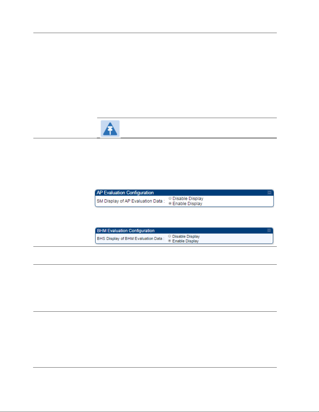
SM Display of AP
Evaluation Data
Or
BHS Display of BHM
Evaluation Data
provides no encryption on the air link.
(Data Encryption Standard): An over-the-air link encryption option
that uses secret 56-bit keys and 8 parity bits. DES performs a series of bit
permutations, substitutions, and recombination operations on blocks of
data. DES encryption does not affect the performance or throughput of
the system.
(Advanced Encryption Standard): An over-the-air link encryption
option that uses the Rijndael algorithm and 128-bit keys to establish a
higher level of security than DES.
AES products are certified as
compliant with the Federal Information Processing Standards (FIPS 197)
in the U.S.A.
This parameter is applicable to BHM.
Allows operators to suppress the display of data about this AP/BHM on
the AP/BHM Evaluation tab of the Tools page in all SMs/BHS that
register. The factory default setting for SM Display of AP Evaluation Data
or BHS Display of BHM Evaluation Data is enabled display.
PMP 450/450i Series – SM display of AP Evaluation Data parameter
Web, Telnet, FTP
Session Timeout
IP Access Control
Allowed Source IP 1
to 3
PTP 450/450i Series – BHS display of BHM Evaluation Data parameter
Enter the expiry in seconds for remote management sessions via
, or
access to the AP/BHM.
You can permit access to the AP/BHM from any IP address (
addresses that you specify (
three
any IP address
If you selected
parameter, then you must populate at least one of the three
parameters or have no access permitted to the AP from any IP
address. You may populate as many as all three.
If you selected
parameter, then no entries in this parameter are read, and access from
all IP addresses is permitted.
) or limit it to access from only one, two, or three IP
). If you select
, then you must populate at least one of the
parameters or have no access permitted from
for the
for the
Page 7-119
,

Chapter 7: Configuration Configuring security
HTTP Only
HTTPS Only
HTTP and HTTPS
SNMPv2c Only
SNMPv3 Only
SNMPv2c and SNMPv3
Enable
Disable
Enable
Disable
Enable
Disable
Web Access
The Radio supports secured and non-secured web access protocols.
Select suitable web access from drop down list:
•
– provides non-secured web access. The radio to be
accessed via http://<IP of Radio>.
•
– provides a secured web access. The radio to be
accessed via https://<IP of Radio>.
•
http and https.
SNMP
This option allows to configure SNMP agent communication version. It
can be selected from drop down list :
•
•
– Enables SNMP v2 community protocol.
– Enables SNMP v3 protocol. It is a secured
communication protocol.
•
Telnet This option allows to
FTP This option allows to
TFTP This option allows to
– If enabled, the radio can be accessed via both
– It enables both the protocols.
and
and
and
Telnet access to the Radio.
FTP access to the Radio.
TFTP access to the Radio.
Page 7-120

Chapter 7: Configuration Configuring security
Security page - 450 Platform Family SM
The security page of 450 Platform Family SM is explained in Table 139.
Table 139 Security attributes –450 Platform Family SM
Page 7-121

Chapter 7: Configuration Configuring security
Attribute
Meaning
Use Default Key
Use Key above
AAA
AP Pre-
sharedKey
Phase 1
Authentication Key
Select Key
Enforce
Authentication
Phase 1
Only if the AP to which this SM will register requires authentication,
specify the key that the SM will use when authenticating. For alpha
characters in this hex key, use only upper case.
The
selection specifies the predetermined key for
authentication in Wireless Manager
The
selection specifies the 32-digit hexadecimal key that
is permanently stored on both the SM and the WM
The SM may enforce authentication types of
and
. The SM will not finish the registration process if the AP is not
using the configured authentication method (and the SM locks out the
AP for 15 minutes).
The protocols supported for the
authentication are
Tunneled Transport Layer
EAPTTLS (Extensible Authentication Protocol
Security) or MSCHAPv2 (Microsoft
Challenge-Handshake Authentication Protocol version 2).
(Outside Identity) phase of
Page 7-122

Chapter 7: Configuration Configuring security
Phase 2
Phase 2
PAP
CHAP
MSCHAP
(
Enable Realm
Identity
Realm
Identity
Identity
Realm
Realm
Username
Username
Username
Username
Username
Username
Password
Confirm
Password
Password
Password
Password
Delete
Choose File,
Import Certificate
In
Use
Delete
Use Default Certificates
RADIUS
Certificate Settings
Phase 2
Identity/Realm
Username
Select the desired
the
options
of
(Challenge Handshake
Microsoft’s version of CHAP, version 2 is used). The protocol
(Inside Identity) authentication protocol from
(Password Authentication Protocol),
Authentication
Protocol), and
must be
consistent with the authentication protocol configured on the RADIUS
server.
If Realms are being used, select
identity in the
match the Phase 1/Outer Identity and
server. The default
and configure an outer
field and a Realm in the
Realm
configured in the RADIUS
is “anonymous”. The
field. These must
can be up
to
128 non-special (no diacritical markings) alphanumeric characters. The
default
special alphanumeric
Configure an outer Identity in the
Phase
1/Outer
default Phase 1/Outer
alphanumeric
Enter a
configured for the SM on
the SM’s MAC address. The
(no diacritical markings) alphanumeric
is
“canopy.net”. The
can also be up to 128 non-
characters.
field. This must match the
Identity username configured in the RADIUS server. The
Identity
can be up to 128 non-special (no
characters.
is “anonymous”. The
diacritical
markings)
for the SM. This must match the username
the
RADIUS server. The default
can be up
characters.
to
128 non-special
is
Password
Upload Certificate
File
Enter the desired password for the SM in the
for the SM on the RADIUS server.
The
alphanumeric
To upload a certificate manually to a SM, first load it in a known place
on your PC
the Certificate description blocks to delete a certificate to provide space
for your certificate. Click on
certificate, and click the
radio to use the new certificate.
When a certificate is in use, after the SM successfully registers to an
AP, an indication of
certificate being
The public certificates installed on the SMs are used with the private
certificate on the
encryption
Up to 2 certificates can be resident on a SM. An installed certificate can
be deleted
block on the Configuration >
certificates, click the
fields. The
can be up to 128 non-special (no
characters
or network
system.
by
clicking the
must match the password configured
The
default
drive, then click on a
browse to
button, and then reboot the
will appear in the description block of the
used.
RADIUS
server to provide a public/private key
button in the certificate’s description
Security
tab. To restore the 2 default
parameter block and reboot the
Page 7-123
diacritical
button on one of
the
button in
radio.
and
is “password”.
markings)
location of the
the

Chapter 7: Configuration Configuring security
None
DES
AES
Ethernet Access Disabled
Network Accessibility
Public
Note
Ethernet Access Enabled
IP Access Filtering
Disabled
IP Access Filtering Enabled
IP Access
Filtering Enabled
Allowed Source IP
IP Access Filtering Enabled
IP Access Control
Allowed
Source IP
Encryption Setting
Web, Telnet, FTP
Session Timeout
Ethernet Access
Specify the type of airlink security to apply to this SM. The encryption
setting must match the encryption setting of the AP.
provides no encryption on the air link.
(Data Encryption Standard): An over-the-air link encryption option
that uses secret 56-bit keys and 8 parity bits. DES performs a series of bit
permutations, substitutions, and recombination operations on blocks of
data. DES encryption does not affect the performance or throughput of
the system.
(Advanced Encryption Standard): An over-the-air link encryption
option that uses the Rijndael algorithm and 128-bit keys to establish a
higher level of security than DES.
AES products are certified as
compliant with the Federal Information Processing Standards (FIPS 197)
in the U.S.A.
Enter the expiry in seconds for remote management sessions via HTTP,
telnet, or FTP access to the SM.
If you want to prevent any device that is connected to the Ethernet port
of the SM from accessing the management interface of the SM, select
. This selection disables access through this
port to via HTTP (the GUI), SNMP, telnet, FTP, and TFTP. With this
selection, management access is available through only the RF interface
via either an IP address (if
is set to
on the
SM) or the Session Status or Remote Subscribers tab of the AP.
IP Access Control
Allowed Source IP 1
to 3
If you want to allow management access through the Ethernet port,
select
parameter.
You can permit access to the SM from any IP address (
) or limit it to access from only one, two, or three IP addresses
that you specify (
address
If you selected
parameter, then you must populate at least one of the three
address. You may populate as many as all three.
This setting does not prevent a device connected to the
Ethernet port from accessing the management interface of
other SMs in the network. To prevent this, use the IP Access
Filtering Enabled selection in the IP Access Control
parameter of the SMs in the network. See IP Access Control
below.
. This is the factory default setting for this
). If you select
, then you must populate at least one of the three
parameters or have no access permitted from any IP
for the
parameters or have no access permitted to the SM from any IP
Page 7-124

Chapter 7: Configuration Configuring security
IP Access Filtering Disabled
IP Access Control
HTTP Only
HTTPS Only
HTTP and HTTPS
SNMPv2c Only
SNMPv3 Only
SNMPv2c and SNMPv3
Enable
Disable
Enable
Disable
Enable
Disable
Enable
Disable
Enable
Disable
Web Access
SNMP
If you selected
for the
parameter, then no entries in this parameter are read, and access from
all IP addresses is permitted.
A subnet mask may be defined for each entry to allow for filtering
control based on a range of IP addresses.
The Radio supports secured and non-secured web access protocols.
Select suitable web access from drop down list:
•
– provides non-secured web access. The radio to be
accessed via http://<IP of Radio>.
•
– provides a secured web access. The radio to be
accessed via https://<IP of Radio>.
•
– If enabled, the radio can be accessed via both
http and https.
This option allows to configure SNMP agent communication version. It
can be selected from drop down list :
•
•
– Enables SNMP v2 community protocol.
– Enables SNMP v3 protocol. It is secured
communication protocol.
•
– It enables both the protocols.
Telnet This option allows to
FTP This option allows to
TFTP This option allows to
and
and
and
Telnet access to the Radio.
FTP access to the Radio.
TFTP access to the Radio.
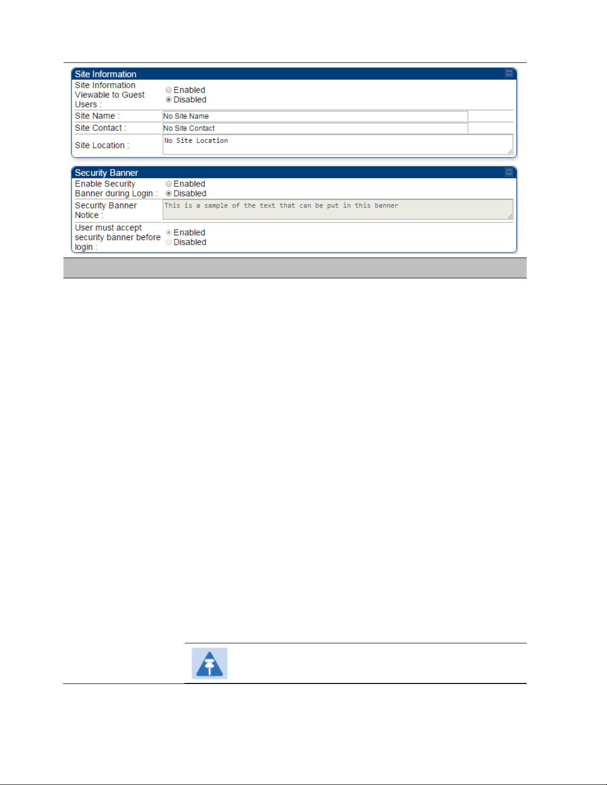
Site Name Specify a string to associate with the physical module.
Site Contact Enter contact information for the module administrator.
Site Location Enter information about the physical location of the module.
Enable Security
Banner during Login
Security Banner
Notice
User must accept
security banner
before login
User can enter ASCII (0-9a-zA-Z newline, line-feed are allowed) text up-to
1300 characters.
accepts the security banner.
: The Security Banner Notice will be displayed before login.
: The Security Banner Notice will not be displayed before login.
: login area (username and password) will be disabled unless user
: User can’t login to radio without accepting security banner.
Page 7-125
Chapter 7: Configuration Configuring security
Attribute
Meaning
None
DES
AES
Security page –450 Platform Family BHS
The Security page of 450 Platform Family BHS is explained in Table 140.
Table 140 Security attributes - 450 Platform Family BHS
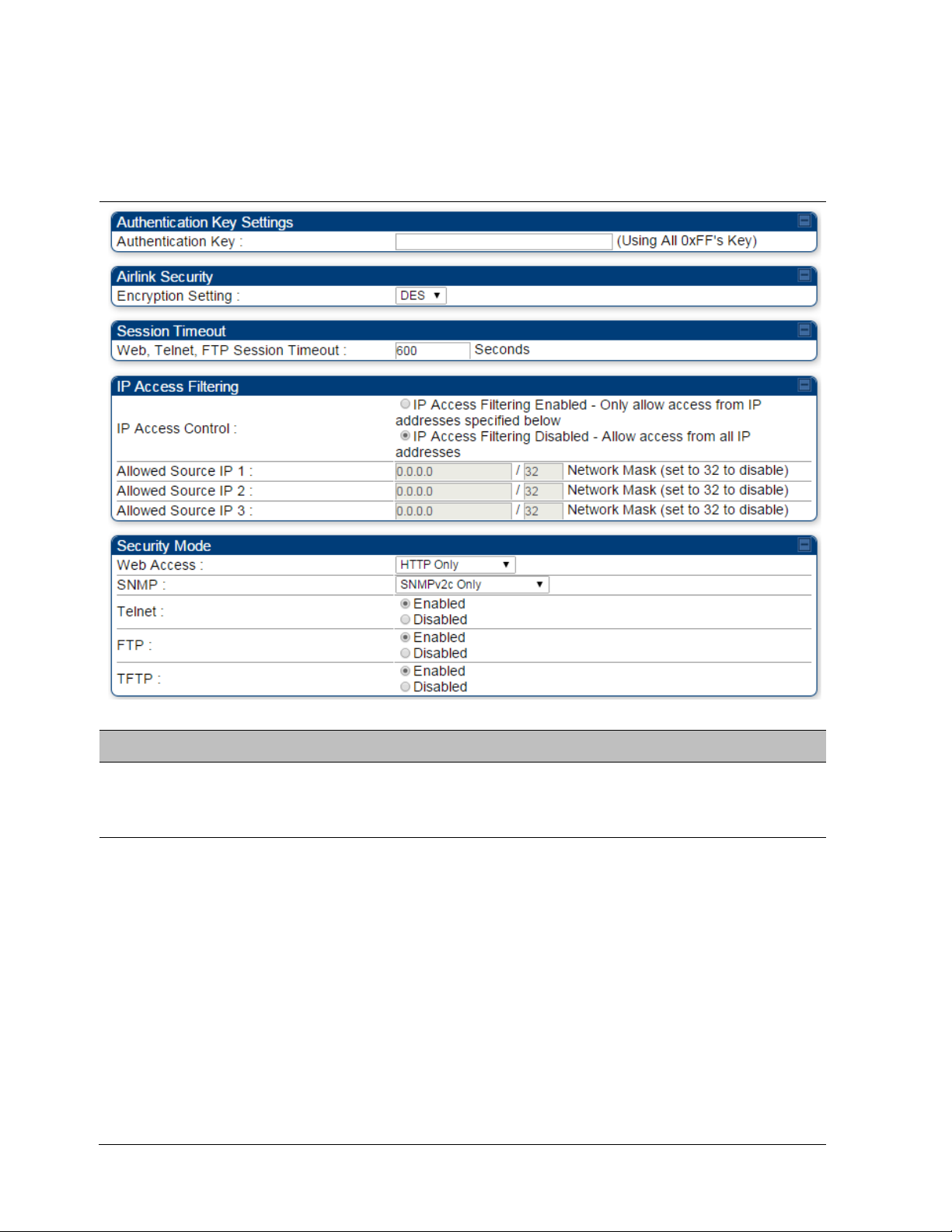
Authentication Key
Encryption Setting
Only if the BHM to which this BHS registers requires an authentication,
specify the key that the BHS will use when authenticating. For alpha
characters in this hex key, use only upper case.
Specify the type of airlink security to apply to this BHS. The encryption
setting must match the encryption setting of the BHM.
provides no encryption on the air link.
(Data Encryption Standard): An over-the-air link encryption option
that uses secret 56-bit keys and 8 parity bits. DES performs a series of bit
permutations, substitutions, and recombination operations on blocks of
data. DES encryption does not affect the performance or throughput of
the system. It is factory default setting.
(Advanced Encryption Standard): An over-the-air link encryption
option that uses the Rijndael algorithm and 128-bit keys to establish a
higher level of security than DES.
compliant with the Federal Information Processing Standards (FIPS 197)
in the U.S.A.
AES products are certified as
Page 7-126

Chapter 7: Configuration Configuring security
IP Access
Filtering Disabled
IP Access Filtering Enabled
IP
Access Filtering Enabled
Allowed Source IP
IP Access Filtering Enabled
IP Access Control
Allowed
Source IP
IP Access Filtering Disabled
IP Access Control
HTTP Only
HTTPS Only
HTTP and HTTPS
SNMPv2c Only
SNMPv3 Only
SNMPv2c and SNMPv3
Enable
Disable
Enable
Disable
Enable
Disable
Web, Telnet, FTP
Session Timeout
IP Access Control
Allowed Source IP 1
to 3
Web Access
Enter the expiry in seconds for remote management sessions via HTTP,
telnet, or FTP access to the BHS.
You can permit access to the BHS from any IP address (
) or limit it to access from only one, two, or three IP
addresses that you specify (
). If you select
, then you must populate at least one of the
three
parameters or have no access permitted from
any IP address
If you selected
for the
parameter, then you must populate at least one of the three
parameters or have no access permitted to the BHS from any
IP address. You may populate as many as all three.
If you selected
for the
parameter, then no entries in this parameter are read, and access from
all IP addresses is permitted.
A subnet mask may be defined for each entry to allow for filtering
control based on a range of IP addresses.
The Radio supports secured and non-secured web access protocols.
Select suitable web access from drop down list:
•
– provides non-secured web access. The radio to be
accessed via http://<IP of Radio>.
•
– provides a secured web access. The radio to be
accessed via https://<IP of Radio>.
•
– If enabled, the radio can be accessed via both
http and https.
SNMP
Telnet This option allows to
FTP This option allows to
TFTP This option allows to
This option allows to configure SNMP agent communication version. It
can be selected from drop down list :
•
•
communication protocol.
•
– Enables SNMP v2 community protocol.
– Enables SNMP v3 protocol. It is secured
– It enables both the protocols.
and
and
and
Telnet access to the Radio.
FTP access to the Radio.
TFTP access to the Radio.
Page 7-127

Chapter 7: Configuration Configuring radio parameters
Configuring radio parameters
• PMP 450m Series – configuring radio on page 7-129
• PMP/PTP 450i Series – configuring radio on page 7-129
• PMP 450b Series - configuring radio on page 7-153
• PMP/PTP 450 Series – configuring radio on page 7-157
• Custom Frequencies page on page 7-174
• DFS for 5 GHz Radios on page 7-177
• MIMO-A mode of operation on page 7-179
• Improved PPS performance of 450 Platform Family on page 7-181
Page 7-128
Chapter 7: Configuration Configuring radio parameters
Note
PMP 450m Series – configuring radio
Radio page - PMP 450m AP 5 GHz
The Radio tab of the PMP 450m AP contains some of the configurable parameters that define how
an AP operates.
Only the frequencies available for your region and the selected Channel bandwidth are
displayed.
Table 141 PMP 450m AP Radio attributes - 5 GHz
Page 7-129
Chapter 7: Configuration Configuring radio parameters
Attribute
Meaning
None
Note for PMP 450m:
Note:
Subscriber Color Code Wait Period for Idle
Subscriber Color Code Rescan
Subscriber Color Code Wait Period for Idle
Subscriber Color Code Wait Period for Idle
Subscriber Color Code Rescan
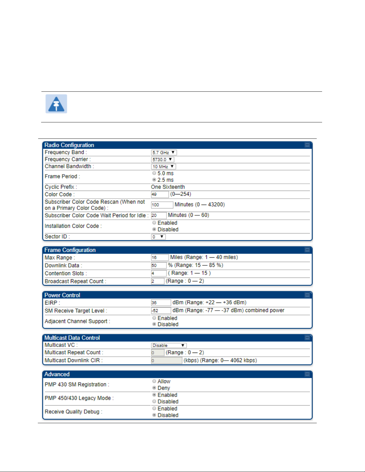
Frequency Band Select the desired operating frequency band.
Frequency Carrier
Specify the frequency for the module to transmit. The default for this
parameter is
. For a list of channels in the band, see the drop-down
list on the radio GUI.
Channel Bandwidth
The channel size used by the radio for RF transmission. The setting for
the channel bandwidth must match between the AP and the SM. The
supported Channel Bandwidths are 5
MHz, 10 MHz, 15 MHz, 20 MHz, 30 MHz, and 40 MHz.
5 ms frame size is not available in 30 MHz and 40 MHz
channel bandwidths.
40 MHz is not supported on PMP 450 AP, but is
supported on PMP 450 SMs.
Frame Period Select the Frame Period of the radio. The supported Frame Periods are:
5 ms and 2.5 ms.
Cyclic Prefix
OFDM technology uses a cyclic prefix, where a portion of the end of a
symbol (slot) is repeated at the beginning of the symbol to allow multipathing to settle before receiving the desired data. A 1/16 cyclic prefix
means that for every 16 bits of throughput data transmitted, an
additional bit is used.
Color Code
Specify a value from 0 to 254. For registration to occur, the color code of
the SM and the AP must match. Color code is not a security feature.
Instead, color code is a management feature, typically for assigning each
sector a different color code.
Color code allows you to force a SM to register to only a specific AP,
even where the SM can communicate with multiple APs. The default
setting for the color code value is 0. This value matches only the color
code of 0 (not all 255 color codes).
Subscriber Color
Code Rescan (When
not on a Primary
Color Code)
This timer may be utilized to initiate SM rescans in order to register to an
AP configured with the SM‘s primary color code.
The time (in minutes) for a subscriber to rescan (if this AP is not
configured with the SM‘s primary color code). This timer will only fire
once – if the
configured with a nonzero value and the
expires, the
zero value and the
will immediately go into rescan mode
timer is
is started. If the
timer is configured with a
timer expires, the SM
Page 7-130

Chapter 7: Configuration Configuring radio parameters
Subscriber Color
Code Wait Period for
Idle
Installation Color
Code
The time (in minutes) for a subscriber to rescan while idle (if this AP is
not configured with the SM’s primary color code). This timer will fire
periodic events. The fired event determines if any RF unicast traffic
(either inbound or outbound) has occurred since the last event. If the
results of the event determine that no RF unicast traffic has occurred
(SM is idle), then the subscriber will rescan.
With this feature enabled on the AP and SM, operators may install and
remotely configure SMs without having to configure matching color
codes between the modules. While the SM is accessible for
configuration from above the AP (for remote provisioning) and below
the SM (for local site provisioning), no user data is passed over the radio
link. When using the Installation Color Code feature, ensure that the SM
is configured with the factory default Color Code configuration (Color
Code 1 is “0”, Color Code 2-10 set to “0” and “Disable”). The status of
the Installation Color Code can be viewed on the AP Eval web GUI page,
and when the SM is registered using the Installation Color Code the
message “SM is registered via ICC – Bridging Disabled!” is displayed in
red on every SM GUI page. The Installation Color Code parameter is
configurable without a radio reboot for both the AP and SM. If a SM is
registered via Installation Color Code and the feature is then disabled,
operators will need to reboot the SM or force it to reregister (i.e. using
Rescan APs functionality on the AP Eval page).
Max Range
Downlink Data
Enter a number of miles (or kilometers divided by 1.61, then rounded to
an integer) for the furthest distance from which a SM is allowed to
register to this AP. Do not set the distance to any greater number of
miles. A greater distance
• does not increase the power of transmission from the AP.
• can reduce aggregate throughput.
For example, with a 20 MHz channel and 2.5 ms frame, every additional
2.24 miles reduces the data air time by one symbol (around 1% of the
frame).
Regardless of this distance, the SM must meet the minimum
requirements for an acceptable link. The parameters have to be selected
so that there is no overlap between one AP transmitting and another AP
receiving. A co-location tool is provided to help with selecting sets of
parameters that allow co-location.
The default value of this parameter is 2 miles (3.2 km).
Specify the percentage of the aggregate throughput for the downlink
(frames transmitted from the AP to the subscriber). For example, if the
aggregate (uplink and downlink total) throughput on the AP is 90 Mb,
then 75% specified for this parameter allocates 67.5 Mb for the downlink
and 22.5 Mb for the uplink. The default for this parameter is 75%. This
parameter must be set in the range of 15% - 85%, otherwise the invalid
input will not be accepted and the previously-entered valid setting is
used.
Page 7-131

Chapter 7: Configuration Configuring radio parameters
Note
Note
Due to CPU load, this will slightly degrade packet per second
Note
In order to prevent self-interference, the frame configuration
needs to align which includes Downlink Data, Max Range
and Contention slots. For DFS regions, the maximum
Downlink % for a 5.4 GHz radio is 75% only.
Contention Slots
(a.k.a. Control Slots)
Broadcast Repeat
Count
EIRP
SM Receive Target
Level
Adjacent Channel
Support
Receive Quality
Debug
This field indicates the number of (reserved) Contention slots configured
by the operator. The SM uses reserved Contention slots and unused data
slots for bandwidth requests. See Contention slots on page 7-178.
For PMP systems broadcast packets are not acknowledged. So they are
sent at the lowest modulation rate 1X. This setting adds an automatic
retransmission to broadcast packets to give SMs that have poor signal a
higher chance to get the packet.
This field indicates the combined power level at which the AP will
transmit, based on the Country Code. It also includes the antenna gain
and array gain.
Each SM’s Transmitter Output Power is automatically set by the AP. The
AP monitors the received power from each SM, and adjusts each SM’s
Transmitter Output Power so that the received power at the AP from that
SM is not greater what is set in this field. This value represents the
transmitted and received power (combined power) perceived on the SM.
For some frequency bands and products, this setting is needed if AP is
operating on adjacent channels with zero guard band.
To aid in link performance monitoring, the AP and SM now report the
number of fragments received per modulation (i.e. QPSK, 16-QAM, 64QAM and 256-QAM) and per channel (polarization).
processing.
Near Field Operation
This parameter is enabled by the Near Field Operation control. This is
only available when the EIRP is set to 22 dBm or below.
When Near Field Operation is enabled, the Near Field Range is used to
apply compensation to the unit’s calibration to support operation in the
near field.
PMP 430 SM
Registration
This field allows to control PMP 430 SMs. It allows to configure whether
PMP 430 SMs are registered to AP or not. By default, it is enabled and
PMP 430 SM registrations are accepted.
When this field is set to disabled, PMP 430 SM’s registrations fail with
reject reason 8. This will cause SMs to lock out the AP for 15 minutes.
This option is not displayed if the Frame Period is set to
5 ms.
Page 7-132

Chapter 7: Configuration Configuring radio parameters
Note
Due to CPU load, this will slightly degrade packet per second
PMP 450/430 Legacy
Mode
Receive Quality
Debug
This setting allows the AP to communicate with SMs on Legacy versions
of software (450 SM earlier than 13.2, 430 SM earlier than 13.4.1). This is
not recommended to be left enabled as it degrades performance. SMs
should then be upgraded to the same version as the AP.
To aid in link performance monitoring, the AP and SM now report the
number of fragments received per modulation (i.e. QPSK, 16-QAM, 64QAM) and per channel (polarization).
processing.
Page 7-133
Chapter 7: Configuration Configuring radio parameters
PMP/PTP 450i Series – configuring radio
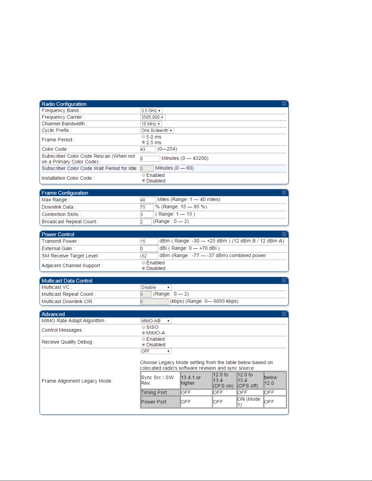
Radio page - PMP 450i AP 3 GHz
The Radio tab of the PMP 450i AP 3 GHz is shown in Figure 145.
Figure 145 PMP 450i AP Radio attributes - 3 GHz
Page 7-134
Chapter 7: Configuration Configuring radio parameters
Note
Note
Refer Table 143 PMP 450i SM Radio attributes – 5 GHz on page 7-141 for parameter
details
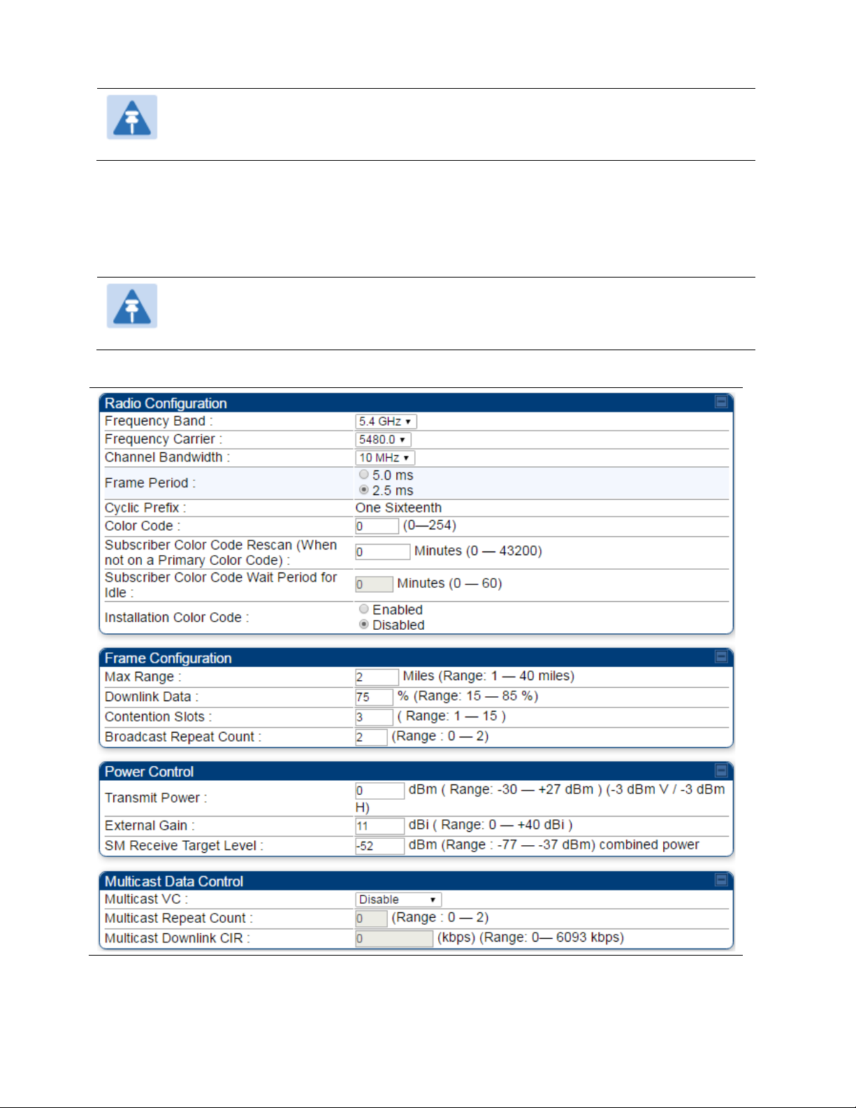
Radio page - PMP 450i AP 5 GHz
The Radio tab of the PMP 450i AP contains some of the configurable parameters that define how
an AP operates.
Only the frequencies available for your region and the selected Channel bandwidth are
displayed.
Table 142 PMP 450i AP Radio attributes - 5 GHz
Page 7-135
Chapter 7: Configuration Configuring radio parameters
Attribute
Meaning
Frequency Band
Frequency Carrier
Alternate Frequency
Carrier 1 and 2
Channel Bandwidth
Cyclic Prefix
Frame Period
Color Code
Subscriber Color
Code Rescan (When
not on a Primary
Color Code)
Subscriber Color
Code Wait Period for
Idle
See Table 141 PMP 450m AP Radio attributes - 5 GHz on page 7-129
These parameters are displayed based on Regional Settings. Refer
Country on page 7-72
See Table 141 PMP 450m AP Radio attributes - 5 GHz on page 7-129
Installation Color
Code
Max Range
Downlink Data See Table 141 PMP 450m AP Radio attributes - 5 GHz on page 7-129
Page 7-136

Chapter 7: Configuration Configuring radio parameters
Contention Slots
(a.k.a. Control Slots)
Broadcast Repeat
Count
Transmitter Output
Power
This field indicates the number of (reserved) Contention slots configured
by the operator. The SM uses reserved Contention slots and unused data
slots for bandwidth requests. See Contention slots on page7-178.
The default is 2 repeats (in addition to the original broadcast packet, for
a total of 3 packets sent for every one needed), and is settable to 1 or 0
repeats (2 or 1 packets for every broadcast).
ARQ (Automatic Repeat reQuest) is not present in downlink broadcast
packets, since it can cause unnecessary uplink traffic from every SM for
each broadcast packet. For successful transport without ARQ, the AP
repeats downlink broadcast packets. The SMs filter out all repeated
broadcast packets and, thus, do not transport further.
The default of 2 repeats is optimum for typical uses of the network as an
internet access system. In applications with heavy download broadcast
such as video distribution, overall throughput is significantly improved
by setting the repeat count to 1 or 0. This avoids flooding the downlink
with repeat broadcast packets.
This value represents the combined power of the AP’s two transmitters.
Nations and regions may regulate transmitter output power. For
example
• 900 MHz, 5.4 GHz and 5.8 GHz modules are available as
connectorized radios, which require the operator to adjust power to
ensure regulatory compliance.
The professional installer of the equipment has the responsibility to
External Gain
SM Receive Target
Level
Multicast VC Data
Rate
• maintain awareness of applicable regulations.
• calculate the permissible transmitter output power for the module.
• confirm that the initial power setting is compliant with national or
regional regulations.
• confirm that the power setting is compliant following any reset of
the module to factory defaults.
This value needs to correspond to the published gain of the antenna
used to ensure the radio will meet regulatory requirements.
See Table 141 PMP 450m AP Radio attributes - 5 GHz on page 7-129
This pull down menu of the Multicast Data Control screen helps in
configuring multicast packets to be transmitted over a dedicated channel
at a configurable rate of 1X, 2X, 4X or 6X. The default value is “Disable”.
If set to the default value, all multicast packets are transmitted over the
Broadcast VC data path. This feature is available only for the PMP 450
Series and is not backward compatible with PMP 430 series of radios.
Page 7-137

Chapter 7: Configuration Configuring radio parameters
Radio
Configuration
Radio
Configuration
Note
Note
Due to CPU load, this will slightly degrade packet per second
Mode
Behavior (non-900 MHz
radios)
Behavior (FSK 900 MHz
radios)
Multicast Repeat
Count
Multicast Downlink
CIR
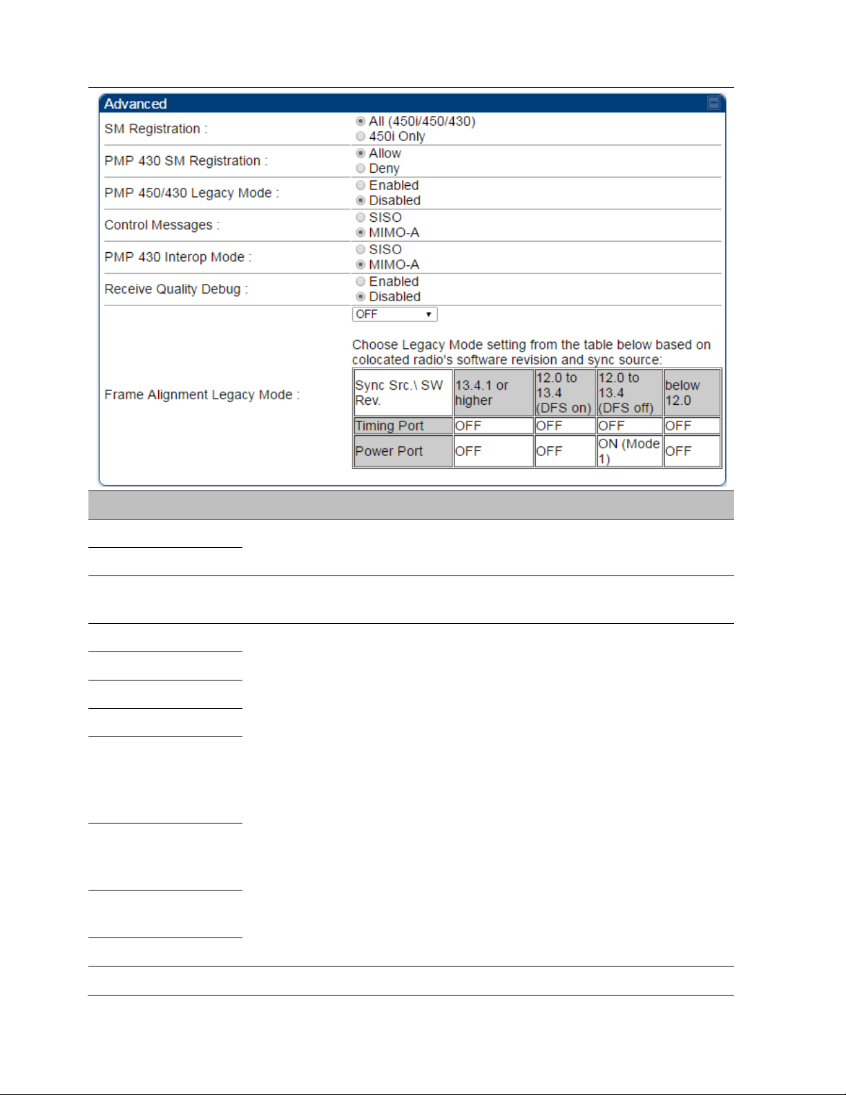
SM Registration All
PMP 430 SM
Registration
This value is the number of packets that are repeated for every multicast
VC packet received on the AP (located under
tab of
Multicast (like Broadcast) packets go over a VC that is shared by all SMs,
so there is no guaranteed delivery. The repeat count is an attempt to
improve the odds of the packets getting over the link. If the user has
issues with packets getting dropped, they can use this parameter to
improve the performance at the cost of the overall throughput possible
on that channel. The default value is 0.
This value is the committed information rate for the multicast downlink
VC (located under the
tab of
). The default value is 0
kbps. The range of this parameter is based on the number of repeat
counts. The higher the repeat count, the lower the range for the
multicast downlink CIR.
This field allows to control registration of all type 450 Platform Family
SM including 430 Series SM(450i/450/430) or 450i Series SM only.
This field allows to control PMP 430 SMs. It allows to configure whether
PMP 430 SMs are registered to AP or not. By default, it is enabled and
PMP 430 SM registrations are accepted.
When this field is set to disabled, PMP 430 SM’s registrations fail with
reject reason 8. This will cause SMs to lock out the AP for 15 minutes.
).
Control Message
PMP 450/430 Legacy
mode
PMP 430 Interop
Mode
Receive Quality
Debug
Frame Alignment
Legacy Mode
This option is not displayed if the Frame Period is set to
5 ms. This option applies only to PMP 450/450i/450m
Series APs - 5 GHz.
Controls whether the control messages are sent in MIMO-B or MIMO-A
mode. MIMO-A is recommended. However, if an AP on 13.2 is
attempting to connect to an SM on 13.1.3 or before, changing to MIMOB may aid in getting the SM registered.
See Table 141 PMP 450m AP Radio attributes - 5 GHz on page 7-129
For n-1 compatibility, In SISO mode this forces the AP to only send
Control and Beacons over one of the RF paths.
To aid in link performance monitoring, the AP and SM now report the
number of fragments received per modulation (i.e. QPSK, 16-QAM, 64QAM) and per channel (polarization).
processing.
Page 7-138

Chapter 7: Configuration Configuring radio parameters
OFF
ON
(Mode 1)
By default frame start is
aligned with devices
with Timing Port
synchronization
If the synchronization
source changes (due to
Autosync or otherwise)
the radio will
dynamically adjust its
frame start to maintain
alignment with the
default frame start
timing
The radio will align with
devices running
software versions from
12.0 to 13.4.
By default frame start is
aligned with FSK 900
MHz devices with
Timing Port
synchronization
If the synchronization
source changes (due to
Autosync or otherwise)
the radio will
dynamically adjust its
frame start to maintain
alignment with the
default frame start
timing
The radio will align with
FSK 900 MHz devices
running software
versions from 12.0 to
13.4.
ON
(Mode 2)
N/A
The radio will align with
FSK 900 MHz devices
with software versions
11.2 or older.
Page 7-139
 Loading...