

Page 1

Note
Chapter 5: Installation
This chapter describes how to install and test the hardware for a PTP 700 link. It contains the
following topics:
• Safety on page 5-2 contains important safety guidelines that must be observed by
personnel installing or operating PTP 700 equipment.
• ODU variants and mounting bracket options on page 5-6 provides details of six different
bracket options, including the type of ODu and range of pole diameters supported by each
option.
• Installing the ODU and top LPU on page 5-7 describes how to mount and ground a
Connectorized+Integrated or Connectorized ODU, and how to mount and ground the top
LPU.
• Install external antennas on page 5-14 describes how to mount and connect an external
antenna for the Connectorized or Connectorized+Integrated ODU.
• Installing the copper Cat5e Ethernet interface on page 5-16 describes how to install the
copper Cat5e power over Ethernet interface from the ODU (PSU port) to the PSU.
• Installing the PSU on page 5-24 describes how to install the AC+DC Enhanced Power
Injector power supply unit for the PTP 700.
• Installing a PTP-SYNC unit on page 5-26 describes how to install a PTP-SYNC unit for TDD
synchronization.
• Installing a GPS receiver on page 5-30 describes how to install a GPS receiver as the timing
reference source for PTP-SYNC.
• Installing a NIDU on page 5-40 describes how to install a network indoor unit (NIDU) for
TDM (T1 or E1) interfaces.
• Installing an SFP Ethernet interface on page 5-26 describes how to install an optical or
copper Cat5e Ethernet interface from the ODU (SFP port) to a connected device.
• Installing an Aux Ethernet interface on page 5-55 describes how to install a copper Cat5e
Ethernet interface from the ODU (Aux port) to a connected device.
• Supplemental installation information on page 5-56 contains detailed installation
procedures that are not included in the above topics, such as how to strip cables, create
grounding points and weatherproof connectors.
These instructions assume that LPUs are being installed from the PTP 650/700 LPU
and grounding kit (Cambium part number C000065L007). If the installation does not
require LPUs, adapt these instructions as appropriate.
If LPUs are being installed, only use the five black-capped EMC cable glands supplied
in the LPU and grounding kit. The silver-capped cable glands supplied in the ODU kits
must only be used in PTP 700 installations which do not require LPUs.
Page 5-1
Page 2

Chapter 5: Installation Safety
Warning
Warning
Safety
To prevent loss of life or physical injury, observe the following safety guidelines. In no
event shall Cambium Networks be liable for any injury or damage caused during the
installation of the Cambium PTP 700. Ensure that only qualified personnel install a PTP
700 link.
Hazardous locations
When installing the PTP 700 ATEX/HAZLOC product variants in hazardous locations,
follow the instructions contained in the PTP 700 Series Hazardous Location Guide
(supplied in box with the products), in addition to the instructions in this user guide.
Power lines
Exercise extreme care when working near power lines.
Working at heights
Exercise extreme care when working at heights.
PSU
Always use one of the Cambium PTP 700 Series power supply units (PSU) to power the ODU.
Failure to use a Cambium supplied PSU could result in equipment damage and will invalidate
the safety certification and may cause a safety hazard.
Grounding and protective earth
The Outdoor Unit (ODU) must be properly grounded to protect against lightning. It is the user’s
responsibility to install the equipment in accordance with national regulations. In the USA
follow the requirements of the National Electrical code NFPA 70-2005 and 780-2004 Installation
of Lightning Protection Systems. In Canada, follow Section 54 of the Canadian Electrical Code.
These codes describe correct installation procedures for grounding the outdoor unit, mast,
lead-in wire and discharge unit, size of grounding conductors and connection requirements for
grounding electrodes. Other regulations may apply in different countries and therefore it is
recommended that installation of the outdoor unit be contracted to a professional installer.
Page 5-2
Page 3

Chapter 5: Installation Safety
DC supply
To power the ODU from a DC supply, use the PTP 650/700 AC+DC Enhanced Power Injector
(PSU) (Cambium part number C000065L002). Ensure that the DC power supply meets the
requirements specified in PSU DC power supply on page 3-15.
Powering down before servicing
Before servicing PTP 700 equipment, always switch off the power supply and unplug it from
the PSU.
Do not disconnect the RJ45 drop cable connectors from the ODU while the PSU is connected to
the power supply. Always remove the AC or DC input power from the PSU.
Primary disconnect device
The main power supply is the primary disconnect device. The AC+DC Enhanced power injector
is fused on the DC input. Some installations will also require an additional circuit breaker or
isolation switch to be fitted in the DC supply.
External cables
Safety may be compromised if outdoor rated cables are not used for connections that will be
exposed to the outdoor environment. For outdoor copper Cat5e Ethernet interfaces, always use
Cat5e cable that is gel-filled and shielded with copper-plated steel. Alternative types of drop
cable are not supported by Cambium Networks.
Drop cable tester
The PSU output voltage may be hazardous in some conditions, for example in wet weather. Do
NOT connect the drop cable tester to the PSU, either directly or via LPUs.
Grounding PTP-SYNC
In order to meet the safety requirements for deployment in Australia and New Zealand
(AS/NZS 60950-1), the PTP-SYNC unit, if deployed, must be grounded to a Protective Ground in
accordance with Local Electrical Regulations.
RF exposure near the antenna
Strong radio frequency (RF) fields will be present close to the antenna when the transmitter is
on. Always turn off the power to the ODU before undertaking maintenance activities in front of
the antenna.
Page 5-3
Page 4

Chapter 5: Installation Safety
Minimum separation distances
Ensure that personnel are not exposed to unsafe levels of RF energy. The units start to radiate
RF energy as soon as they are powered up. Never work in front of the antenna when the ODU
is powered. Install the ODUs so as to provide and maintain the minimum separation distances
from all persons. For minimum separation distances, see Calculated distances on page 4-24.
Grounding and lightning protection requirements
Ensure that the installation meets the requirements defined in Grounding and lightning
protection on page 3-11.
Grounding cable installation methods
To provide effective protection against lightning induced surges, observe these requirements:
• Grounding conductor runs are as short, straight and smooth as possible, with bends and
curves kept to a minimum.
• Grounding cables must not be installed with drip loops.
• All bends must have a minimum radius of 200 mm (8 in) and a minimum angle of 90°. A
diagonal run is preferable to a bend, even though it does not follow the contour or run
parallel to the supporting structure.
• All bends, curves and connections must be routed towards the grounding electrode
system, ground rod, or ground bar.
• Grounding conductors must be securely fastened.
• Braided grounding conductors must not be used.
• Approved bonding techniques must be used for the connection of dissimilar metals.
Siting ODUs and antennas
ODUs, external antennas and GPS receivers for PTP-SYNC are not designed to survive direct
lightning strikes. For this reason they must be installed in Zone B as defined in Lightning
protection zones on page 3-11. Mounting in Zone A may put equipment, structures and life at
risk.
Thermal Safety
The ODU enclosure may be hot to the touch when in operation. The ODU must not be operated
in ambient temperatures exceeding 40°C unless mounted in a Restricted Access Location. For
more information, see ODU ambient temperature limits on page 3-13.
Page 5-4
Page 5

Chapter 5: Installation Safety
Warning
Alerte
Do not install the ODU in a location where the ambient temperature could exceed 40°C
unless this is a Restricted Access Location as defined by EN 60950-1.
L’unité externe ne doit pas être installée dans un endroit où la température ambiante
est supérieure à 40C à moins que l’accès soit limité au personnel autorisé.
Page 5-5
Page 6

Chapter 5: Installation ODU variants and mounting bracket options
Table 113
Bracket
Pole diameter
ODU variants
Bracket part
number
Note
ODU variants and mounting bracket options
Mounting bracket options
The PTP 700 series supports five mounting bracket options. Select the optimum mounting
bracket arrangement based on the pole diameter and the ODU variant:
Mounting bracket
(integrated)
Mounting bracket
(connectorized)
Extended integrated
mounting bracket
Mounting bracket
(integrated) with large
diameter extension kit
ODU mounting bracket part numbers
The connectorized mounting bracket is included with the PTP 700 Connectorized ODU.
Order a bracket separately for PTP 700 Connectorized+Integrated ODUs.
40 mm to 82 mm
(1.6 inches to 3.2
inches)
40 mm to 82 mm
(1.6 inches to 3.2
inches)
89 mm OR 114 mm
(3.5 inches OR 4.5
inches)
89 mm to 229 mm
(3.5 inches to 9.0
inches)
PTP 700
Connectorized+Integrated
PTP 700 Connectorized N000065L032
PTP 700 Connectorized
PTP 700
Connectorized+Integrated
PTP 700 Connectorized
PTP 700
Connectorized+Integrated
N000065L031
N000065L030
N000065L031
with
N000065L042
Page 5-6
Page 7
Chapter 5: Installation Installing the ODU and top LPU
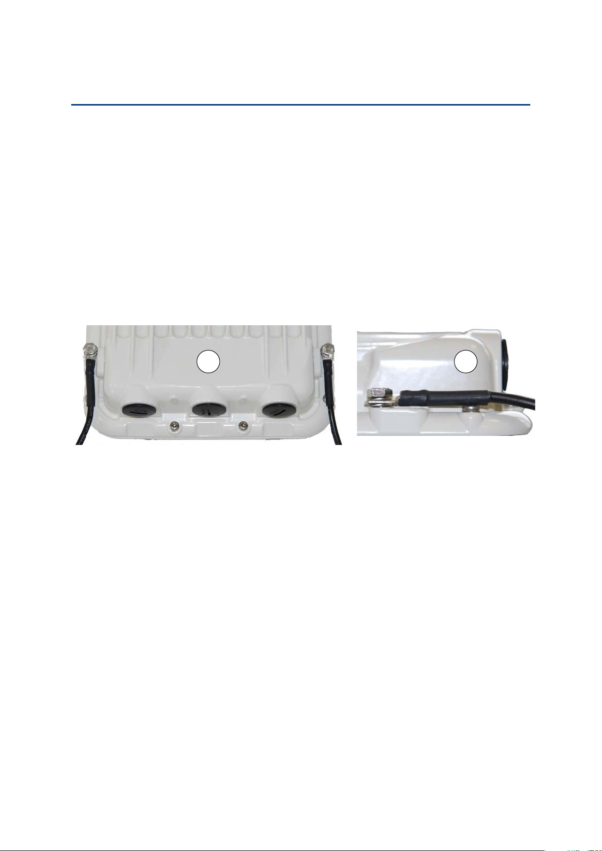
1
Fasten one ground cable to each ODU grounding point using the M6 (small) lugs: one is for the
top LPU (M6 lug at other end) and the other is for the tower or building (M10 lug at other end).
It does not matter which cable goes on which ODU grounding point.
2
T
21
Installing the ODU and top LPU
To install the ODU and top LPU, use the following procedures:
• Attach ground cables to the ODU on page 5-7
• Mount the ODU on the mast on page 5-7
• Mount the top LPU on page 5-12
• Interconnect and ground the ODU and top LPU on page 5-12
Attach ground cables to the ODU
ighten both ODU grounding bolts to a torque of 5 Nm (3.9 lb ft).
Mount the ODU on the mast
Select the most appropriate bracket mounting arrangement from the options listed in
Mounting bracket options on page 5-6. Refer to individual procedures below for each of the
options:
• Mounting bracket (integrated) on page 5-8
• Mounting bracket (connectorized) on page 5-9
• Extended integrated mounting bracket on page 5-10
• Mounting bracket (integrated) with large diameter extension kit on page 5-11
The procedure for the Mounting bracket (connectorized) can be readily adapted to attach the
ODU to a horizontal pole of similar size.
The procedure for the Mounting bracket (integrated) and the Extended integrated mounting
bracket can be adapted to attach the ODU to a suitable horizontal pole, but the adjustment of
azimuth angle is necessarily limited compared with an installation on a vertical pole.
Page 5-7
Page 8
Chapter 5: Installation Installing the ODU and top LPU
Caution
1
2
3
4
5
1 2
4 5
7
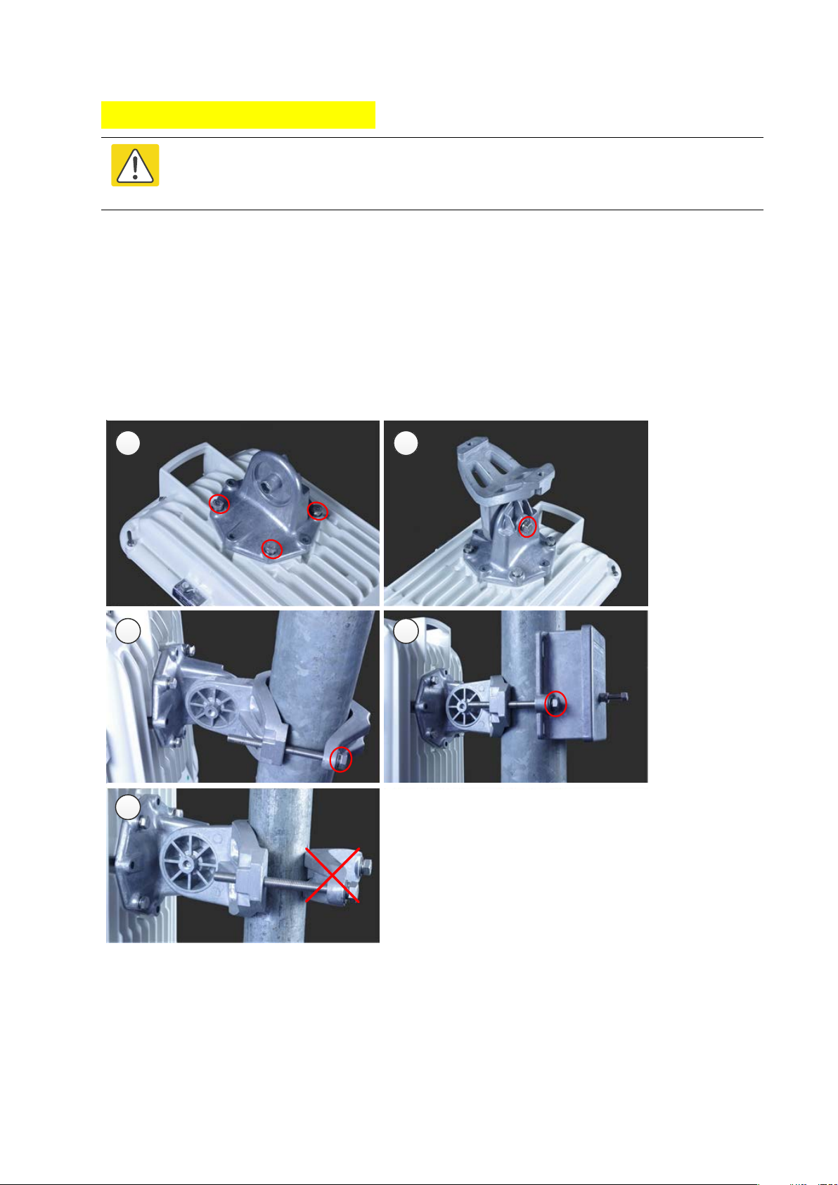
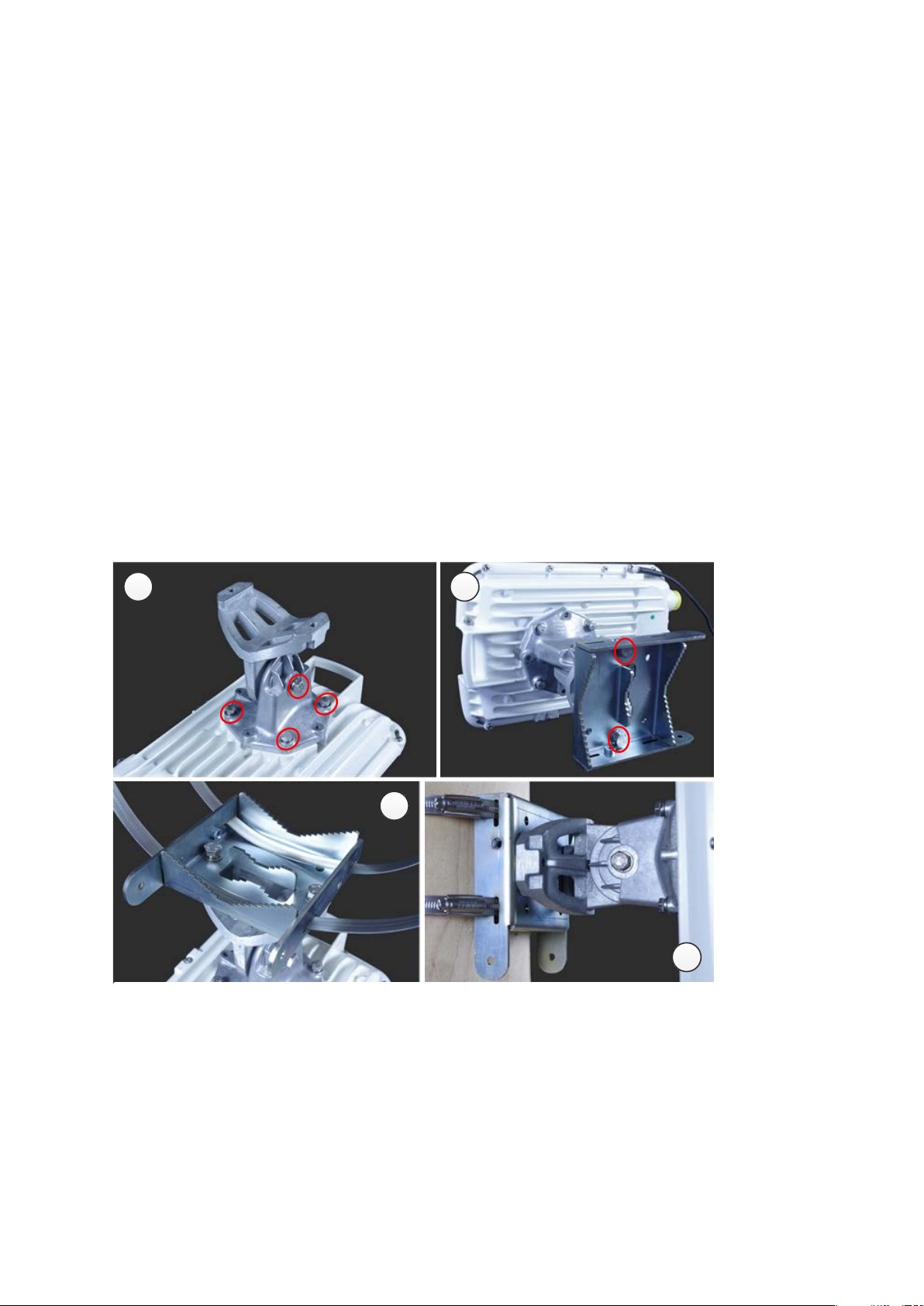
Mounting bracket (integrated)
Do not reverse the bracket clamp, as this arrangement may lead to failure of the
assembly. Do not over-tighten the bolts as this may lead to failure of the assembly.
Fix the mounting plate to the back of the ODU using the four bolts, and spring and plain
washers provided. Tighten the bolts to a torque setting of 5.0 Nm (3.7 lb ft).
Attach the bracket body to the mounting plate using the M8 bolt, spring and plain washers.
Hoist the ODU to the mounting position.
Attach the bracket body to the pole using the bracket clamp, M8 bolts, and spring and plain
washers. For back-to-back mounting, use the LPU in place of the clamp.
Adjust the elevation and azimuth to achieve visual alignment. Tighten all three bracket bolts to
a torque of 8.0 Nm (6.0 lb ft).
Page 5-8
Page 9
Chapter 5: Installation Installing the ODU and top LPU
1
2
3
4
5
6
1 2
4
5
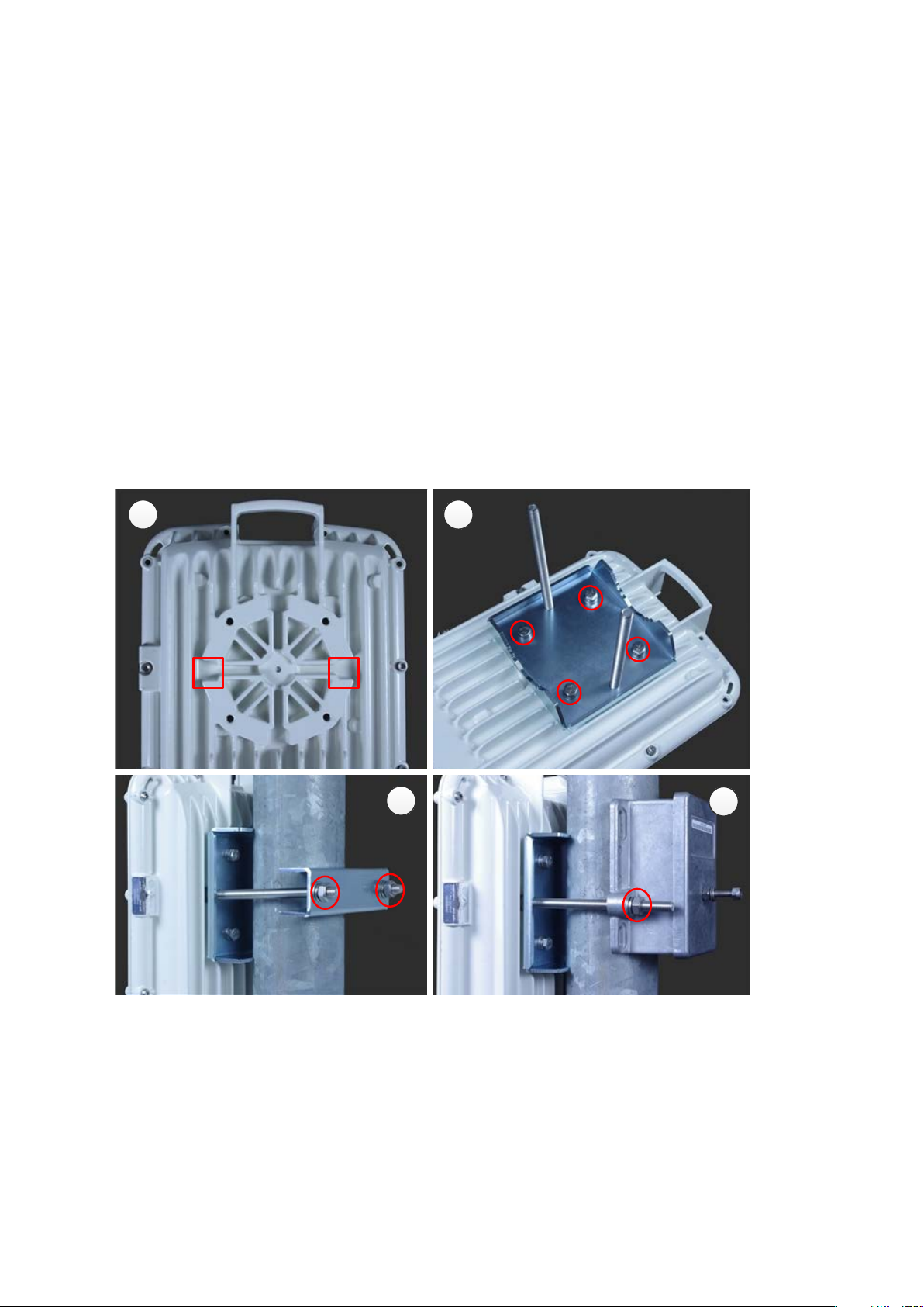
Mounting bracket (connectorized)
Identify the square cavities in the casting on the back of the ODU. These cavities will be used
to accommodate the heads of two M8 bracket bolts.
Fix the mounting plate to the ODU using the four M6 bolts, and spring and plain washers
provided. Ensure that the M8 bolts are correctly held between the mounting plate and the
ODU. Tighten the M6 bolts to a torque setting of 5.0 Nm (3.7 lb ft).
Hoist the ODU to the mounting position.
Attach the bracket body to the pole using the bracket clamp, spring and plain washers, and M8
nuts.
Alternatively, use the LPU in place of the clamp to provide a back-to-back arrangement.
Tighten the two M8 bracket bolts to a torque setting of 8.0 Nm (6.0 lb ft). Do not over-tighten
the bolts as this may lead to failure of the assembly.
Page 5-9
Page 10
Chapter 5: Installation Installing the ODU and top LPU
1
2
3
4
5
6
1
2
5
Extended integrated mounting bracket
Fix the mounting plate to the back of the ODU using the four M6 bolts, and spring and plain
washers provided. Tighten the bolts to a torque setting of 5.0 Nm (3.7 lb ft). The step is common
with the standard integrated bracket.
Attach the bracket body of the extended bracket on the mounting plate on the ODU to using the
M8 bolt and spring and plain washer.
Hoist the ODU to the mounting position.
Select the correct clamp. The larger clamp is intended for poles of diameter 114 mm (4.5
inches). The smaller clamp is intended for poles of diameter 89 mm (3.5 inches).
Attach the bracket body to the pole using the selected bracket clamp, washers and M8 bolts.
Adjust the elevation and azimuth to achieve visual alignment. Tighten all three M8 bracket bolts
to a torque setting of 8.0 Nm (6.0 lb ft). Do not over-tighten the bolts as this may lead to failure
of the assembly.
Page 5-10
Page 11
Chapter 5: Installation Installing the ODU and top LPU
1
2
3
4
5
6
7
1
2
3
5
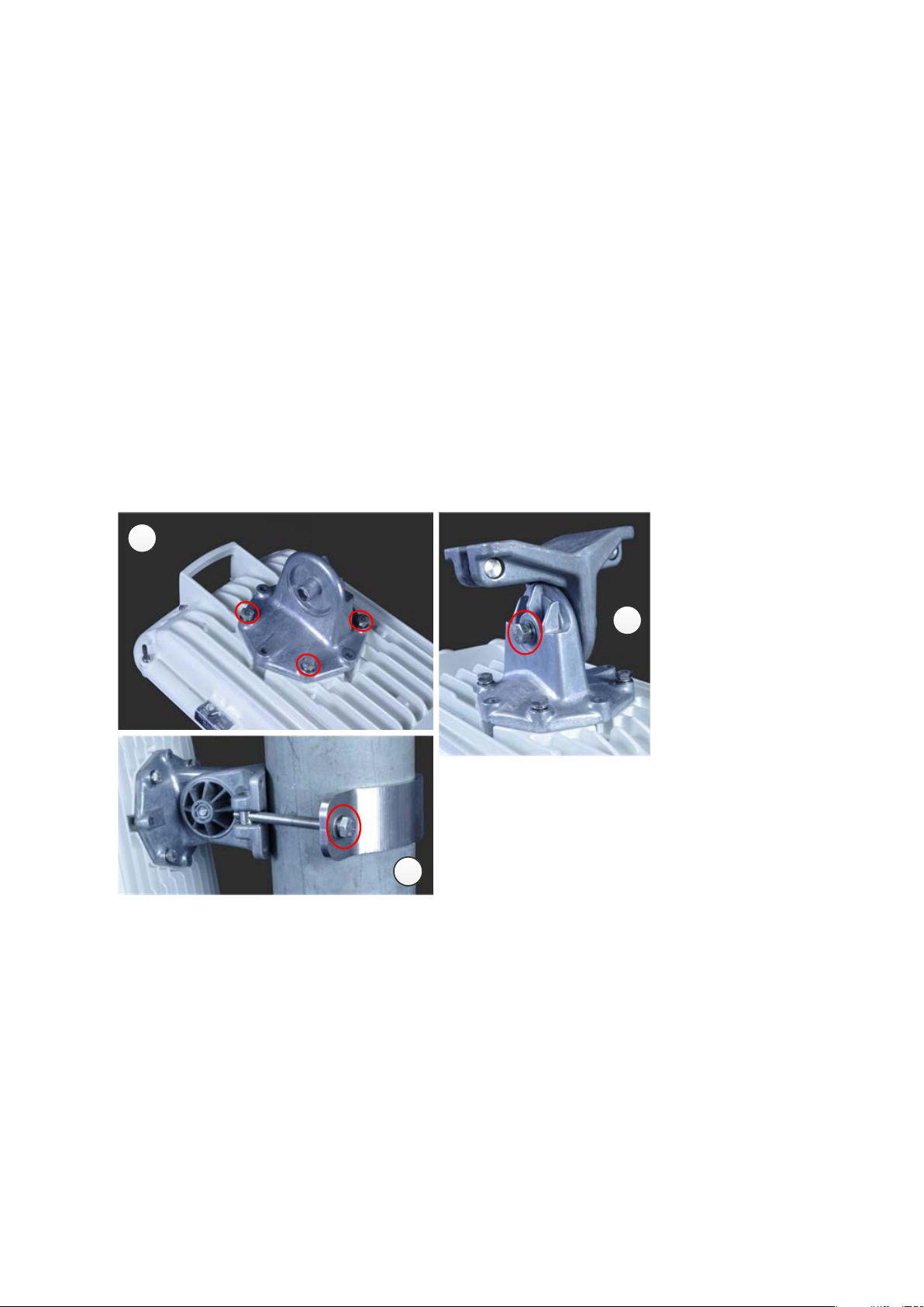
Mounting bracket (integrated) with large diameter extension kit
Fix the mounting plate to the back of the ODU using the bolts and washers provided. Tighten
the four bolts to a torque setting of 5.0 Nm (3.7 lb ft). Attach the bracket body to the mounting
plate using the M8 bolt and spring and plain washer. This is equivalent to the first two steps for
the standard integrated bracket.
Attach the adaptor plate of the large diameter extension kit to the bracket body using the bolts
and washers provided. Tighten the two bolts to a torque setting of 5.0 Nm (3.7 lb ft).
Feed the Jubilee straps through the slots in the adaptor plate.
Hoist the ODU to the mounting position.
Attach the adaptor plate to the pole using the Jubilee straps.
Adjust the azimuth to achieve visual alignment. Tighten the Jubilee straps to a torque setting of
6.0 Nm (4.5 lb ft).
Adjust the elevation to achieve visual alignment. Tighten M8 bracket bolt to a torque setting of
8.0 Nm (6.0 lb ft). Do not over-tighten this bolt as this may lead to failure of the assembly.
Page 5-11
Page 12
Chapter 5: Installation Installing the ODU and top LPU
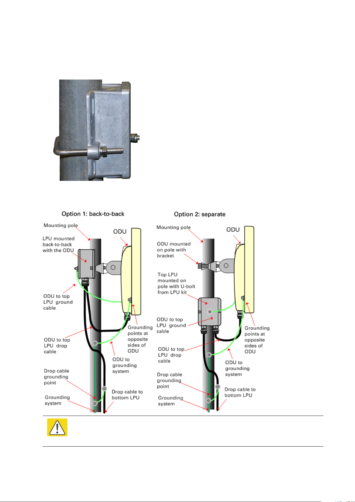
1
For separate LPU mounting, use the U
pole below the ODU. Tighten
Caution
Mount the top LPU
-bolt bracket from the LPU kit to mount the top LPU on the
to a torque setting of 7.0 Nm (5.2 lb ft):
Interconnect and ground the ODU and top LPU
Do not attach grounding cables to the ODU mounting bracket bolts, as this
arrangement will not provide full protection.
Page 5-12
Page 13

Chapter 5: Installation Installing the ODU and top LPU
1
Fasten the ODU grounding cable to the top LPU using the M6 (small) lug.
torque of 5
2
3
add a third ground cable to
Tighten both nuts to a
Nm (3.9 lb ft):
Locking nut
Washer
M6 lug
Washer
Nut
Toothed washer
M6 lug to ODU
Select a tower or building grounding point within 0.3 meters (1 ft) of the ODU bracket. Remove
paint from the surface and apply anti-oxidant compound. Fasten the ODU grounding cable to this
point using the M10 (large) lug.
If local regulations mandate the independent grounding of all devices,
connect the top LPU directly to the grounding system.
Page 5-13
Page 14
Chapter 5: Installation Install external antennas
1
M
When using separate antennas to
achieve spatial diversity, mount
polarization.
2
Connect
part numbers 30010194001 and 30010195001) and
09010091001). Tighten the
3
If
4
Form
channeled towards the connector
5
If the ODU is mounted outdoors, wea
is complete) using PVC tape and
6
Weatherproof the antenna connectors in the same way (unless the antenna manufacturer
specifies a different method).
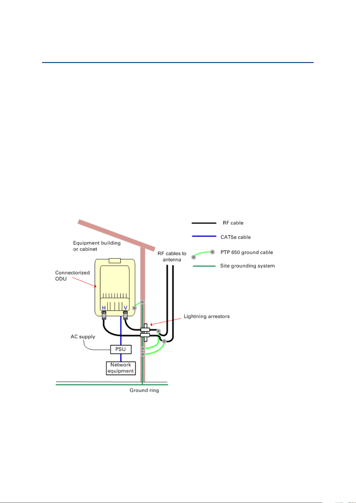
Install external antennas
To mount and connect an external antenna, proceed as follows:
ount the antenna(s) according to manufacturer’s instructions.
one with Horizontal polarization and the other with Vertical
the ODU V and H interfaces to the antenna(s) with RF cable of type LMR-400 (Cambium
N type connectors (Cambium part number
N type connectors to a torque setting of 1.7 Nm (1.3 lb ft).
the ODU is mounted indoors, install lightning arrestors at the building entry point:
drip loops near the lower ends of the antenna cables. These ensure that water is not
s.
therproof the N type connectors (when antenna alignment
self-amalgamating rubber tape.
Page 5-14
Page 15
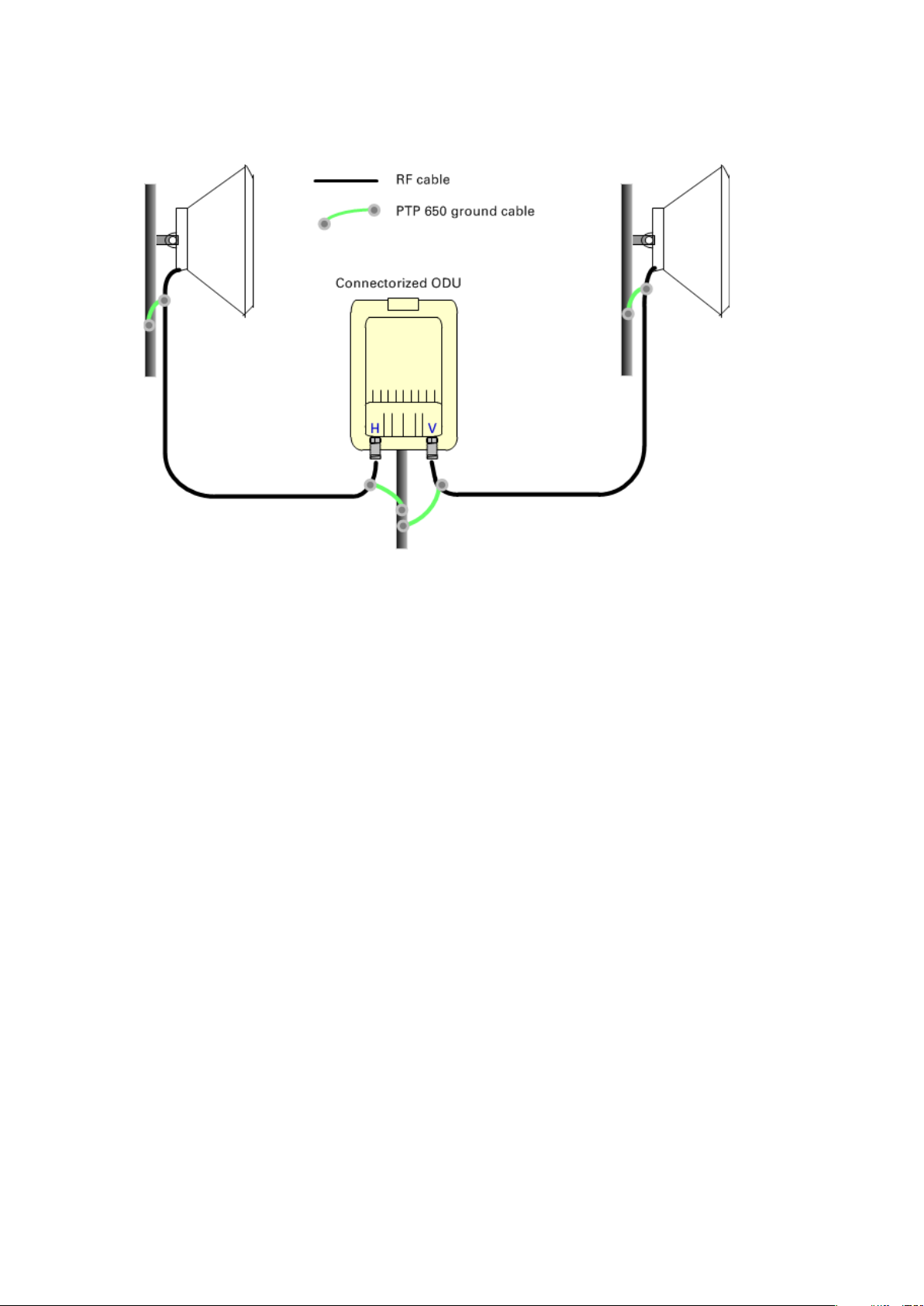
Chapter 5: Installation Install external antennas
7
Ground the
antennas using the Cambium grounding kit (part number 01010419001):
8
Fix the antenna cables to the supporting structure using site approved methods. Ensure that no
und
the wind, as flapping cables are prone to damage and induce unwanted vibrations in the
supporting structure.
antenna cables to the supporting structure within 0.3 meters (1 foot) of the ODU and
ue strain is placed on the ODU or antenna connectors. Ensure that the cables do not flap in
Page 5-15
Page 16
Chapter 5: Installation Installing the copper Cat5e Ethernet interface
Caution
Caution
Caution
1
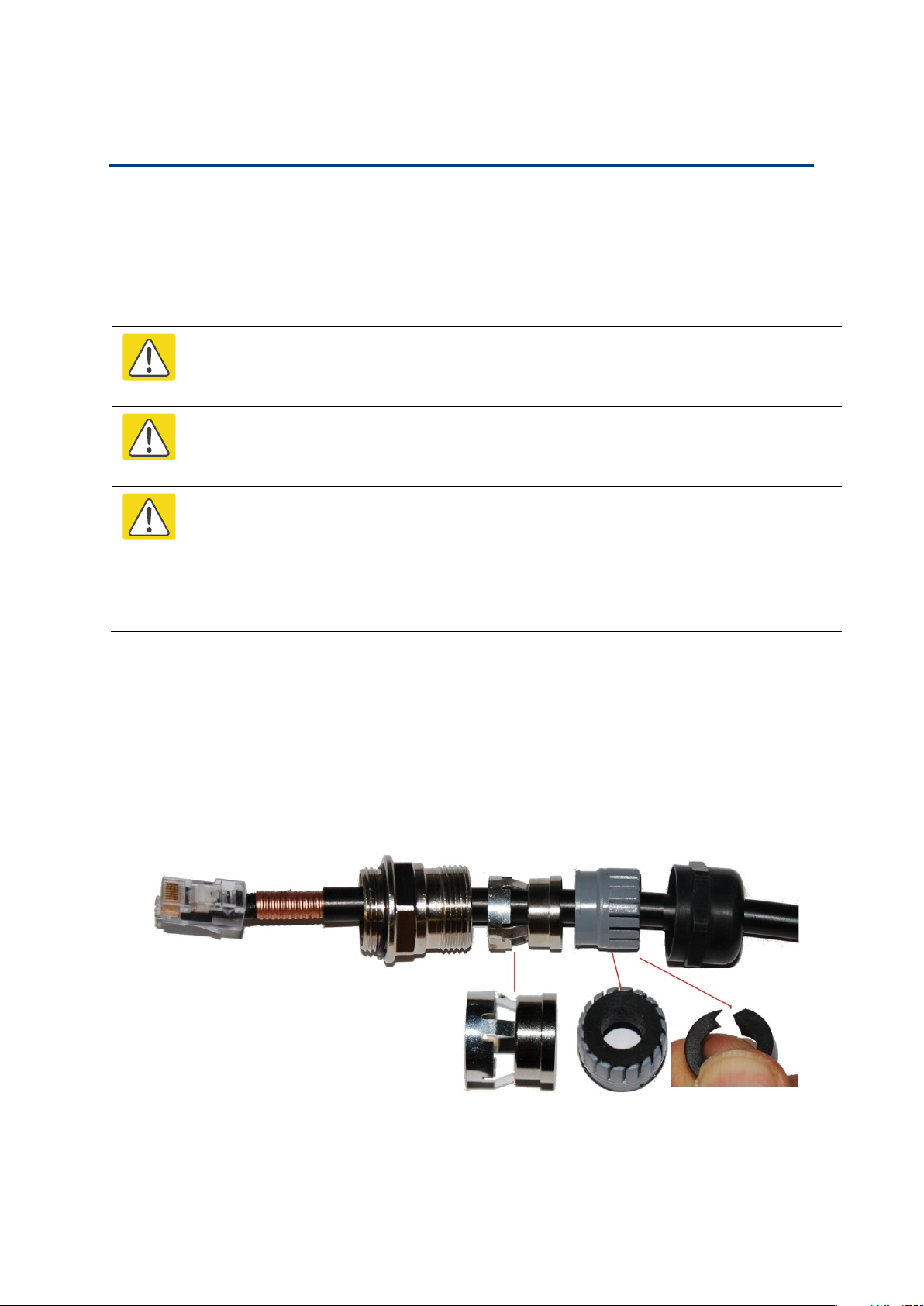
Disassemble the gland and thread each part onto the cable (the rubber bung is sp
Assemble the spring clip and the rubber bung:
Installing the copper Cat5e Ethernet interface
To install the copper Cat5e Ethernet interface, use the following procedures:
• Install the ODU to top LPU drop cable on page 5-16
• Install the main drop cable on page 5-18
• Install the bottom LPU to PSU drop cable on page 5-21
• Test resistance in the drop cable on page 5-23
To avoid damage to the installation, do not connect or disconnect the drop cable when
power is applied to the PSU or network terminating equipment.
Do not connect the SFP or Aux drop cables to the PSU, as this may damage
equipment.
Always use Cat5e cable that is gel-filled and shielded with copper-plated steel.
Alternative types of Cat5e cable are not supported by Cambium Networks. Cambium
Networks supply this cable (Cambium part numbers WB3175 and WB3176), RJ45
connectors (Cambium part number WB3177) and a crimp tool (Cambium part number
WB3211). The LPU and grounding kit contains a 600 mm length of this cable.
Install the ODU to top LPU drop cable
Fit glands to the ODU to top LPU drop cable
Fit EMC strain relief cable glands (with black caps) to both ends of the 600 mm length of
pre-terminated cable. These parts are supplied in the LPU and grounding kit.
lit).
Page 5-16
Page 17
Chapter 5: Installation Installing the copper Cat5e Ethernet interface
2
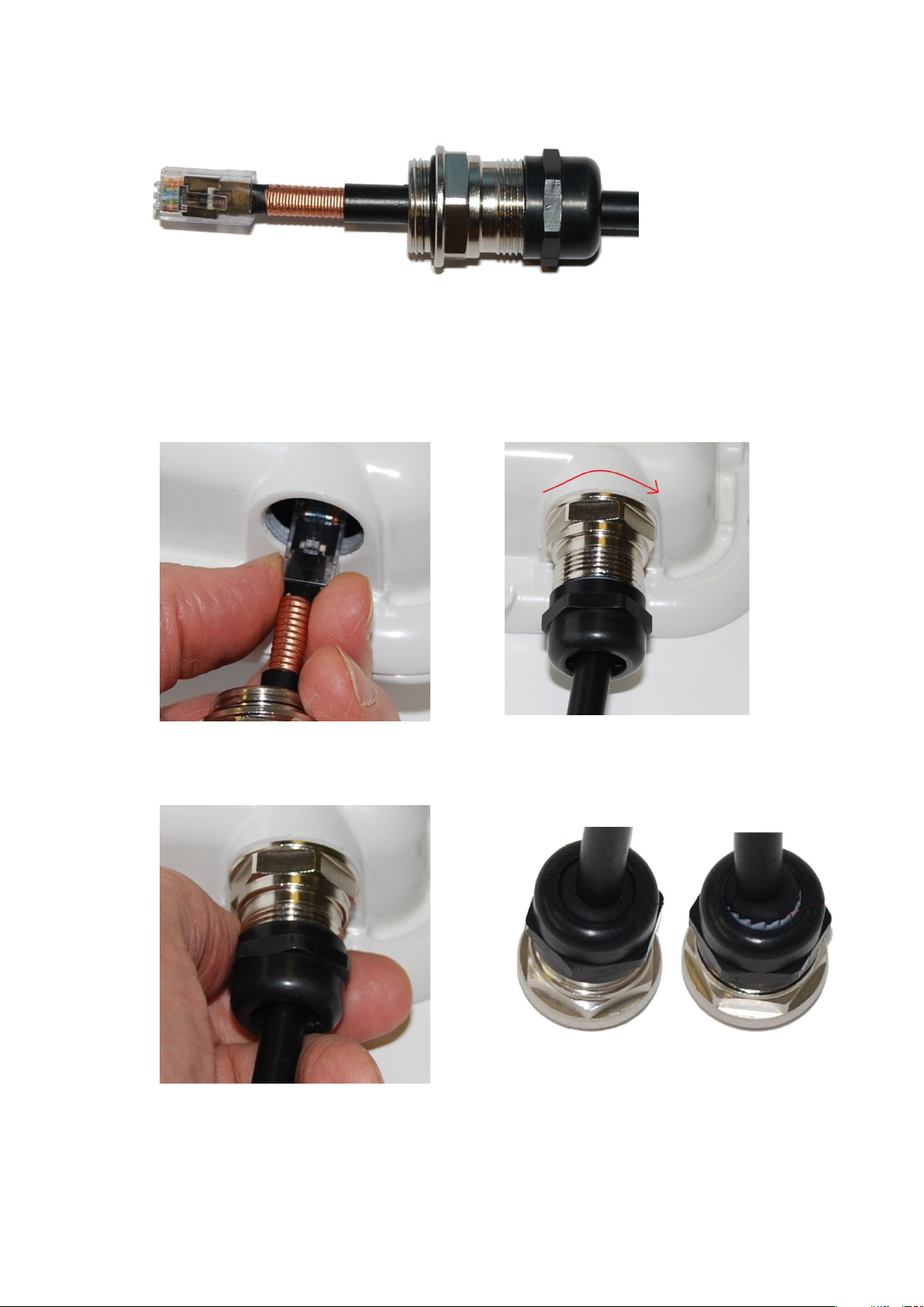
Fit the parts into the body and lightly screw on the gland nut (do not tighten it):
1
2
Connect the drop cable to the ODU (PSU port) and LPU
(a) Plug the RJ45 connector into the socket in the unit, ensuring that it snaps home.
(b) Fit the gland body to the RJ45 port and tighten it to a torque of 5.5 Nm (4.3 lb ft):
(a)
(a) Fit the gland nut and tighten until the rubber seal closes on the cable. (b) Do not overtighten the gland nut, as there is a risk of damage to its internal components:
(a)
(b)
(b)
Correct
Incorrect
Page 5-17
Page 18
Chapter 5: Installation Installing the copper Cat5e Ethernet interface
1
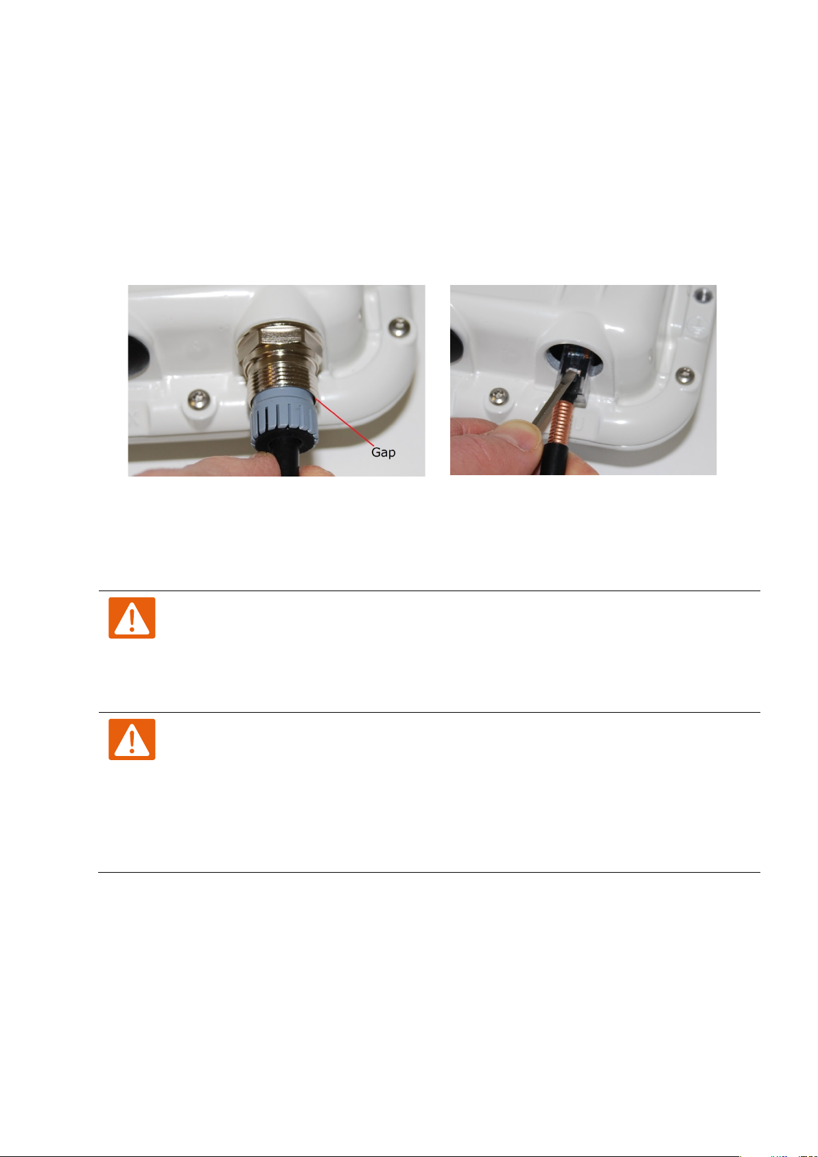
(a) Remove the gland nut. Wiggle the drop cable to release the tension of the gland body. When
the tension in the gland body is released, a gap opens at the point show. Unscrew the gland
body.
(b) Use a small screwdriver to press the
(a)
Warning
Warning
1
Cut the main drop cable to length from the top LPU to the bottom LPU.
2
Slide one or more hoisting grips onto the top end of the
3
Secure the hoisting grip to the cable using a special tool, as recommended by the manufacturer.
Disconnect the drop cable from the LPU or ODU
Use this procedure if it is necessary to remove an EMC strain relief cable gland and RJ45
connector from the ODU (as illustrated) or LPU.
RJ45 locking tab, then remove the RJ45 connector.
Install the main drop cable
The metal screen of the drop cable is very sharp and may cause personal injury.
• ALWAYS wear cut-resistant gloves (check the label to ensure they are cut resistant).
(b)
• ALWAYS wear protective eyewear.
• ALWAYS use a rotary blade tool to strip the cable (DO NOT use a bladed knife).
Failure to obey the following precautions may result in injury or death:
• Use the proper hoisting grip for the cable being installed. If the wrong hoisting grip is
used, slippage or insufficient gripping strength will result.
• Do not reuse hoisting grips. Used grips may have lost elasticity, stretched, or become
weakened. Reusing a grip can cause the cable to slip, break, or fall.
• The minimum requirement is one hoisting grip for each 60 m (200 ft) of cable.
Cut to length and fit hoisting grips
drop cable.
Page 5-18
Page 19
Chapter 5: Installation Installing the copper Cat5e Ethernet interface
Caution
1
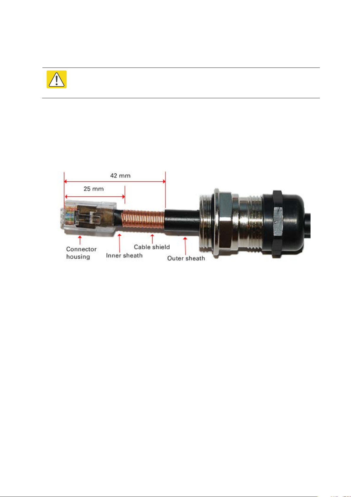
Thread the cable gland (with black cap) onto the main drop cable.
2
Strip the cable outer sheath and fit the RJ45 connector load bar.
3
Fit
cable
Terminate with RJ45 connectors and glands
Check that the crimp tool matches the RJ45 connector, otherwise the cable or
connector may be damaged.
the RJ45 connector housing as shown. To ensure there is effective strain relief, locate the
inner sheath under the connector housing tang. Do not tighten the gland nut:
Page 5-19
Page 20
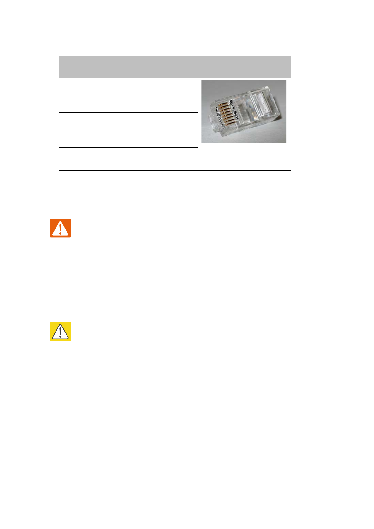
Chapter 5: Installation Installing the copper Cat5e Ethernet interface
Pin
Color
(Supplied cable)
Color
(Conventional)
Pins on plug face
Warning
Caution
1
Hoist the top end of the main drop cable up to the top LPU, following the hoist manufacturer’s
instructions. When the cable is in position, fasten the grip handle to
and remov
2
Connect th
to the ODU (PSU port) and LPU
3
R
4
Attach the main drop cable to the supporting structure
1 Light Orange White/Orange
2 Orange Orange
3 Light Green White/Green
4 Blue Blue
5 Light Blue White/Blue
6 Green Green
7 Light Brown White/Brown
8 Brown Brown
Hoist and fix the main drop cable
Failure to obey the following precautions may result in injury or death:
• Use the hoisting grip to hoist one cable only. Attempting to hoist more than one
cable may cause the hoisting grip to break or the cables to fall.
• Do not use the hoisting grip for lowering cable unless the clamp is securely in place.
• Maintain tension on the hoisting grip during hoisting. Loss of tension can cause
dangerous movement of the cable and result in injury or death to personnel.
• Do not release tension on the grip until after the grip handle has been fastened to the
supporting structure.
• Do not apply any strain to the RJ45 connectors.
Do not lay the drop cable alongside a lightning air terminal.
the supporting structure
e the hoist line.
e main drop cable to the top LPU by following the procedure Connect the drop cable
on page 5-17.
un the main drop cable to the site of the bottom LPU.
Page 5-20
using site approved methods.
Page 21
Chapter 5: Installation Installing the copper Cat5e Ethernet interface
1
2
3
4
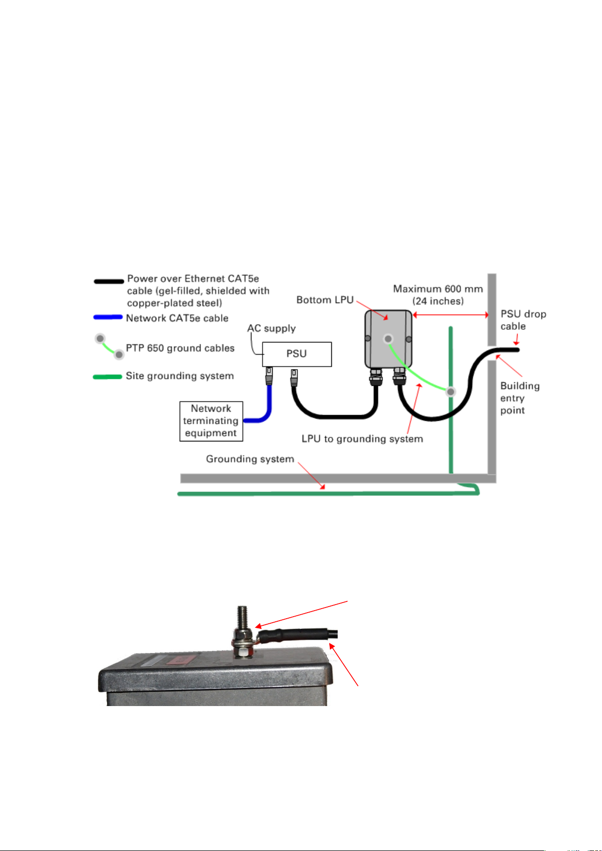
Ground the main drop cable
At all required grounding points, connect the screen of the main drop cable to the metal of the
supporting structure using the cable grounding kit (Cambium part number 01010419001).
Install the bottom LPU to PSU drop cable
Install the bottom LPU
Install the bottom LPU, ground it, and connect it to the main drop cable.
Select a mounting point for the bottom LPU within 600 mm (24 in) of the building entry point.
Mount the LPU vertically with cable glands facing downwards.
Connect the main drop cable to the bottom LPU by following the procedure Connect the drop cable
to the ODU (PSU port) and LPU on page 5-17.
Fasten one ground cable to the bottom LPU using the M6 (small) lug. Tighten both nuts to a
torque of 5 Nm (3.9 lb ft):
Locking nut
Washer
M6 lug
Washer
Nut
Toothed washer
M10 lug to ground
Select a building grounding point near the LPU bracket. Remove paint from the surface and
apply anti-oxidant compound. Fasten the LPU ground cable using the M10 (large) lug.
Page 5-21
Page 22
Chapter 5: Installation Installing the copper Cat5e Ethernet interface
Warning
Caution
1
2
At the LPU end only
4
At the PSU end only
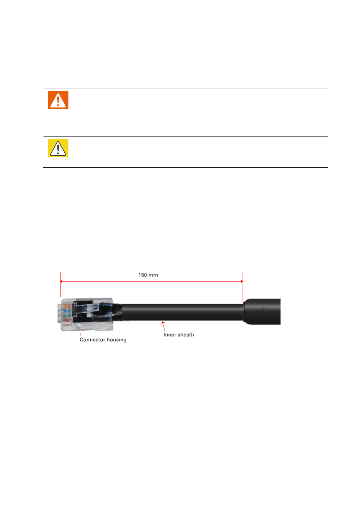
Install the LPU to PSU drop cable
Use this procedure to terminate the bottom LPU to PSU drop cable with RJ45 connectors at
both ends, and with a cable gland at the LPU end.
The metal screen of the drop cable is very sharp and may cause personal injury.
ALWAYS wear cut-resistant gloves (check the label to ensure they are cut resistant).
ALWAYS wear protective eyewear. ALWAYS use a rotary blade tool to strip the cable,
not a bladed knife.
Check that the crimp tool matches the RJ45 connector, otherwise the cable or
connector may be damaged.
Cut the drop cable to the length required from bottom LPU to PSU.
:
• Fit one cable gland and one RJ45 connector by following the procedure Terminate with
RJ45 connectors and glands on page 5-19.
• Connect this cable and gland to the bottom LPU by following the procedure Connect the
drop cable to the ODU (PSU port) and LPU on page 5-17.
: Do not fit a cable gland. Strip the cable outer sheath and fit the RJ45
connector load bar. Fit the RJ45 connector housing. To ensure there is effective strain relief,
locate the cable inner sheath under the connector housing tang:
Page 5-22
Page 23

Chapter 5: Installation Installing the copper Cat5e Ethernet interface
Measure the
resistance
between…
Enter
measured
resistance
To pass test,
resistance must
be…
Circle
“Pass” or
“Fail”
Additional tests and
notes
Test resistance in the drop cable
Connect the bottom end of the copper Cat5e drop cable to a PTP drop cable tester and test that
the resistances between pins are within the correct limits, as specified in the table below. If any
of the tests fail, examine the drop cable for wiring faults. Order the PTP drop cable tester from
the support website (http://www.cambiumnetworks.com/support)
.
Pins 1 and 2 Ohms <20 Ohms
(60 Ohms) (*1)
Pins 3 and 6 Ohms <20 Ohms
(60 Ohms) (*1)
Pins 4 and 5 Ohms <20 Ohms
(60 Ohms) (*1)
Pins 7 and 8 Ohms <20 Ohms
(60 Ohms) (*1)
Pin 1 and screen
(ODU ground)
Pin 8 and screen
(ODU ground)
(*1) A resistance of 20 Ohms is the maximum allowed when the cable is carrying Ethernet.
A resistance of 60 Ohms is the maximum allowed when the cable is carrying only power to the
ODU (when Ethernet is carried by one of the other ODU interfaces).
(*2) Ensure that these resistances are within 10% of each other by multiplying the lowest
resistance by 1.1 – if any of the other resistances are greater than this, the test has failed.
K Ohms >100K Ohms Pass
K Ohms >100K Ohms Pass
Pass
Fail
Pass
Fail
Pass
Fail
Pass
Fail
Fail
Fail
Resistances must be
within 10% of each other
(*2). Circle “Pass” or
“Fail”:
Pass
Fail
These limits apply
regardless of cable
length.
Page 5-23
Page 24
Chapter 5: Installation Installing the PSU
Caution
Caution
1
2
3
Installing the PSU
Install the PTP 650/700 AC+DC Enhanced Power Injector (Cambium part number C000065L002).
Refer to Installing the AC+DC Enhanced Power Injector on page 5-24.
As the PSU is not waterproof, locate it away from sources of moisture, either in the
equipment building or in a ventilated moisture-proof enclosure. Do not locate the
PSU in a position where it may exceed its temperature rating.
Do not plug any device other than a PTP 700 ODU into the ODU port of the PSU. Other
devices may be damaged due to the non-standard techniques employed to inject DC
power into the Ethernet connection between the PSU and the ODU.
Do not plug any device other than a Cambium PTP 700 PSU into the PSU port of the
ODU. Plugging any other device into the PSU port of the ODU may damage the ODU
and device.
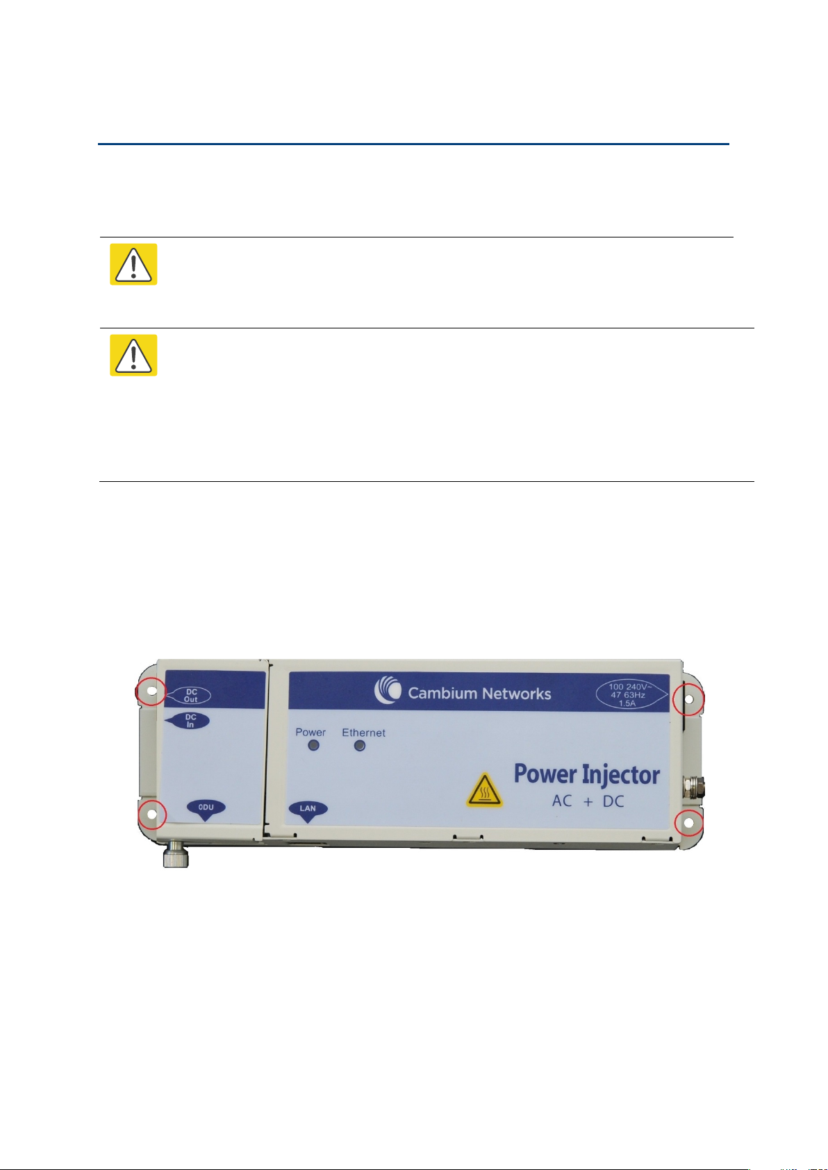
Installing the AC+DC Enhanced Power Injector
Follow this procedure to install the AC+DC Enhanced Power Injector (Cambium part number
C000065L002):
Mount the AC+DC power injector by screwing it to a vertical or horizontal surface using the
four screw holes (circled):
Form a drip loop on the PSU end of the LPU to PSU drop cable. The drip loop ensures that
any moisture that runs down the cable into the cabinet or enclosure cannot enter the PSU.
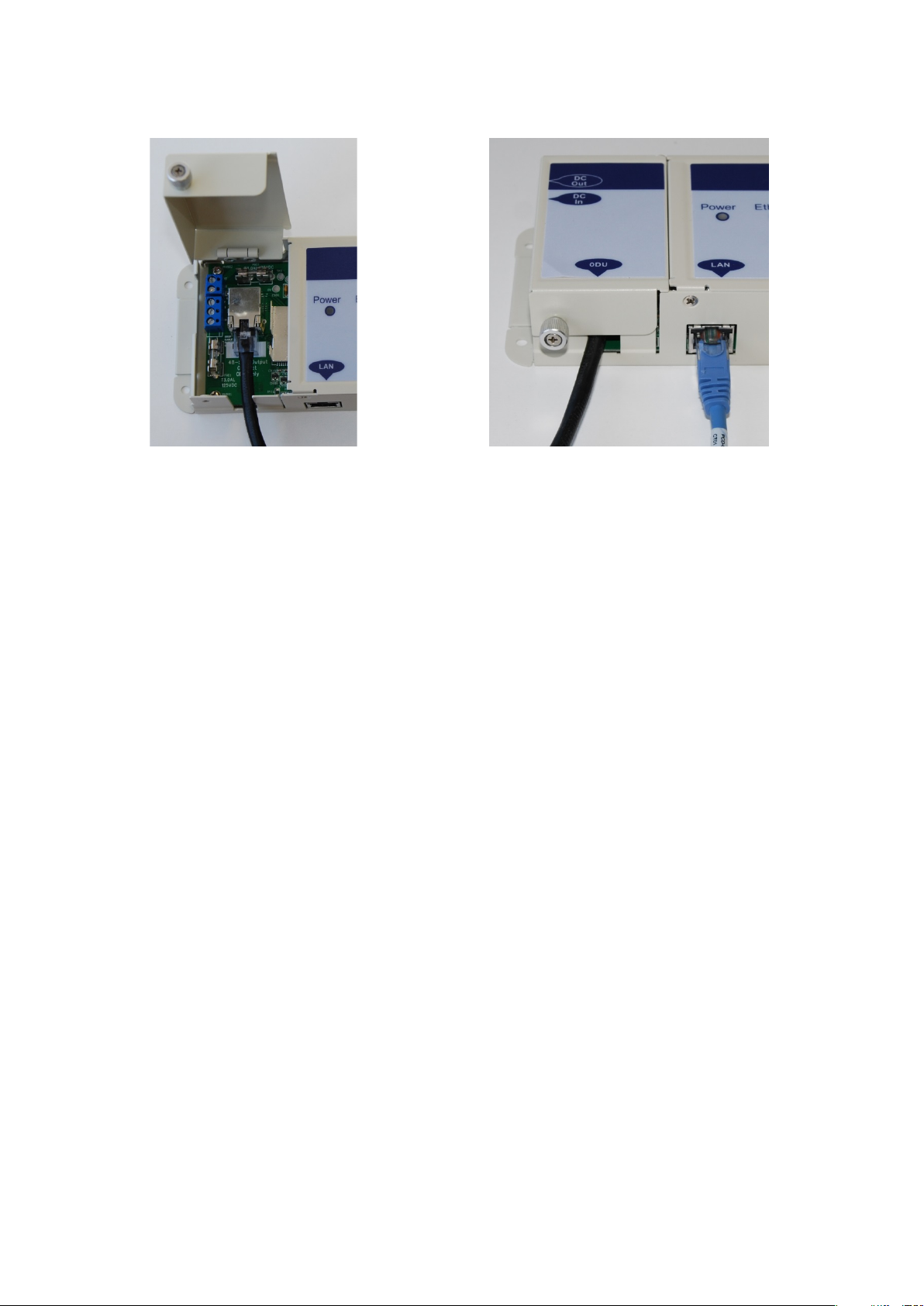
(a) Undo the retaining screw, hinge back the cover and plug the drop cable or the cable from
the PTP-SYNC into the port. (b) Close the cover and secure with the screw. (c) When the
system is ready for network connection, connect the network Cat5e cable to the LAN port of
the PSU:
Page 5-24
Page 25
Chapter 5: Installation Installing the PSU
(a)
(b) and (c)
Page 5-25
Page 26
Chapter 5: Installation Installing a PTP-SYNC unit
Caution
Caution
Figure 112
Installing a PTP-SYNC unit
To install a PTP-SYNC unit (for TDD synchronization), use the following procedures:
• Mounting the PTP-SYNC unit on page 5-26
• Connecting up the PTP-SYNC unit on page 5-27
• Powering up the PTP-SYNC installation on page 5-29
The PTP-SYNC unit must be installed indoors in a non-condensing environment,
otherwise it will be prone to water damage.
To protect the PTP-SYNC from damage, disconnect the power supply from the PSU
before connecting up the PTP-SYNC.
Mounting the PTP-SYNC unit
Use this procedure to install the PTP-SYNC unit in the equipment building, either in a rack or
on a wall.
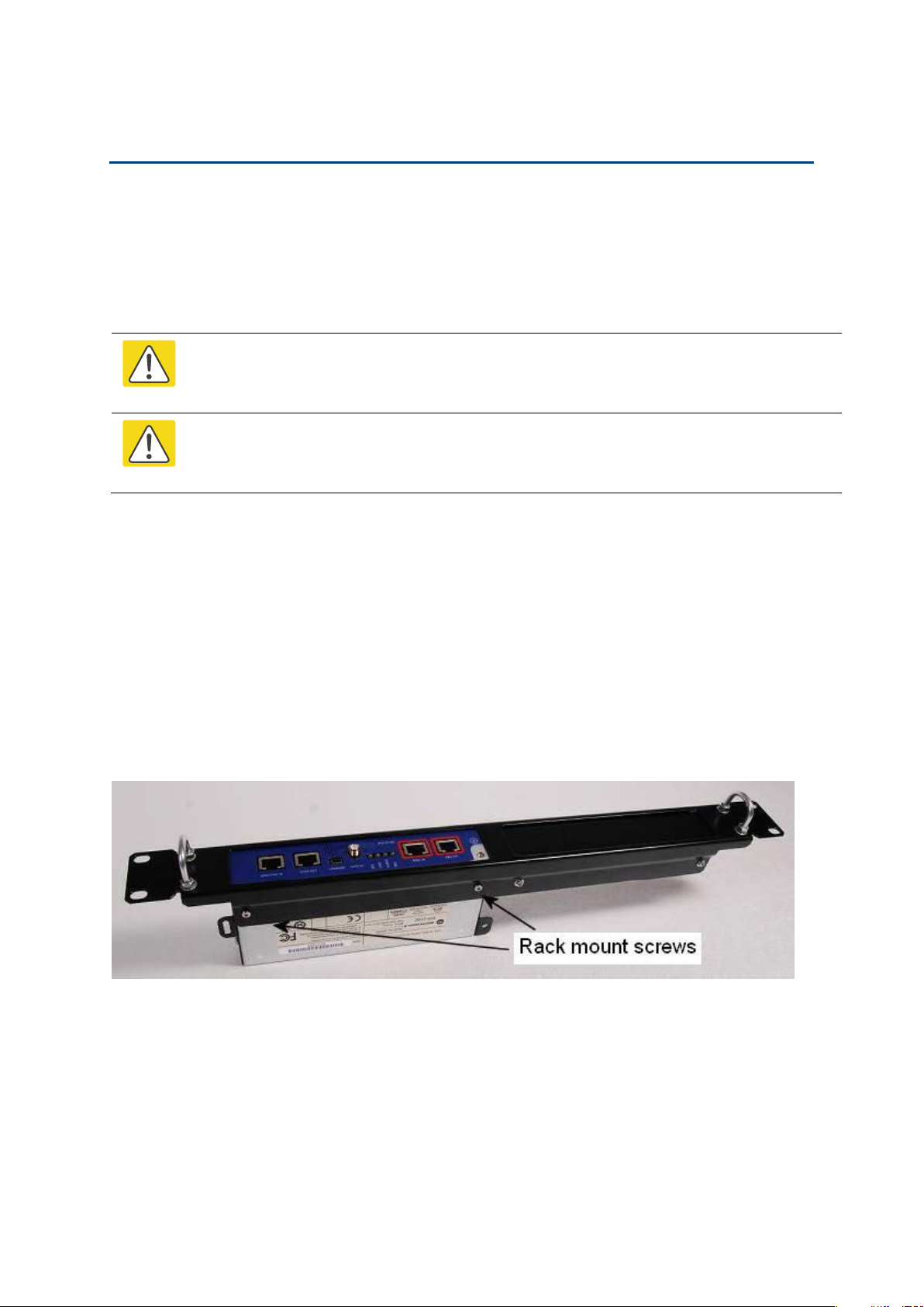
• Racking mounting option: fix the PTP-SYNC to the rack mount using the M3 screws from
the rack mount installation kit (Figure 112).
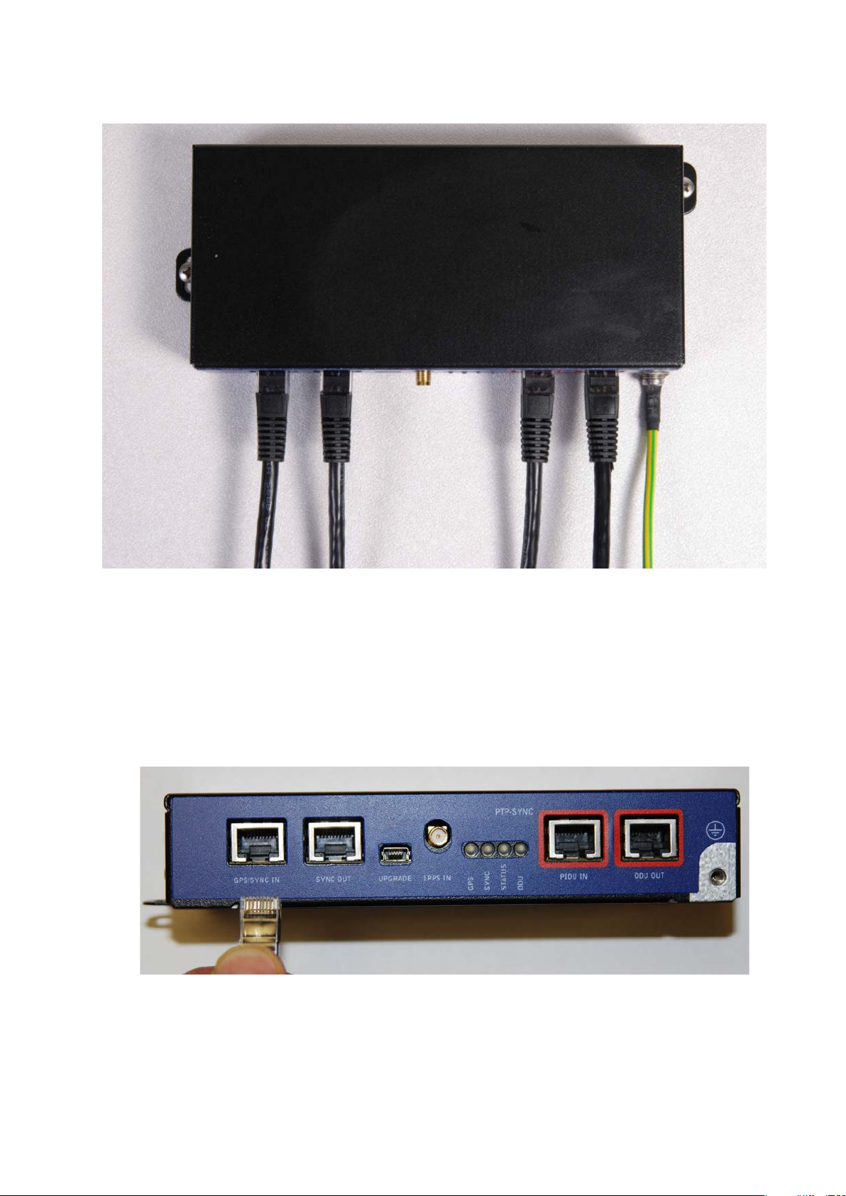
• Wall mounting option: mount the PTP-SYNC vertically with interfaces and cabling facing
downwards (Figure 113).
PTP-SYNC mounted in a rack
Page 5-26
Page 27
Chapter 5: Installation Installing a PTP-SYNC unit
Figure 113
1
2
PTP-SYNC mounted on a wall
Connecting up the PTP-SYNC unit
Use this procedure to connect the PTP-SYNC to the AC+DC Power Injector, ODU, GPS receiver
(if fitted), and LPU (if fitted).
Disconnect the power supply from the AC+DC Power Injector.
If using GPS, connect the cable from the GPS unit to the GPS/SYNC IN port.
Page 5-27
Page 28
Chapter 5: Installation Installing a PTP-SYNC unit
3
4
5
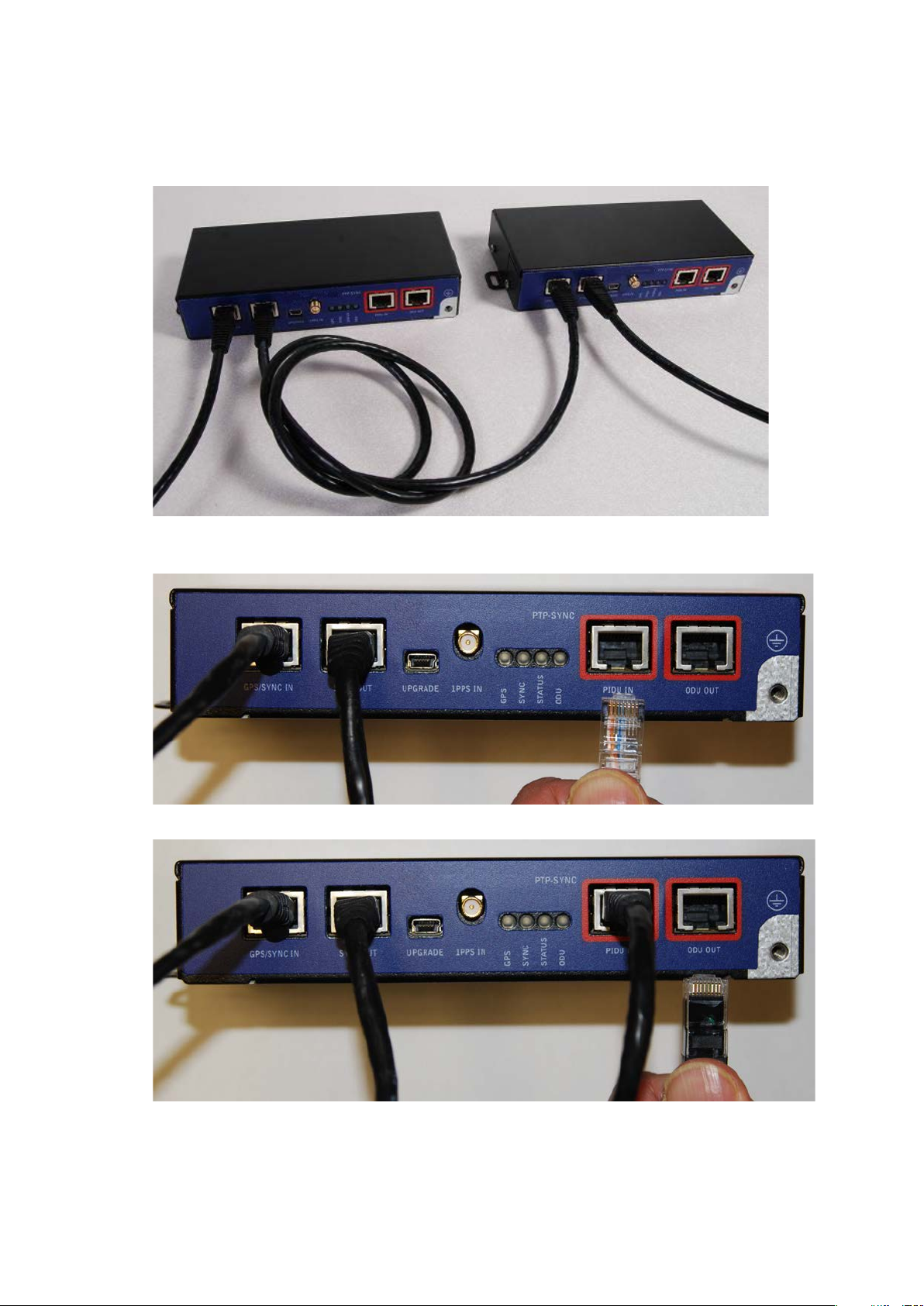
To link clustered PTP-SYNC units, connect the SYNC OUT port of the first PTP-SYNC to the
GPS/SYNC IN port of the second PTP-SYNC in the chain. Repeat for subsequent PTP-SYNC units
in the chain.
Connect the cable from the PSU to the PIDU IN port. A suitable 1 meter cable is included in the
PTP-SYNC kit.
Connect the cable from the ODU to the ODU OUT port.
Page 5-28
Page 29
Chapter 5: Installation Installing a PTP-SYNC unit
6
Caution
1
2
3
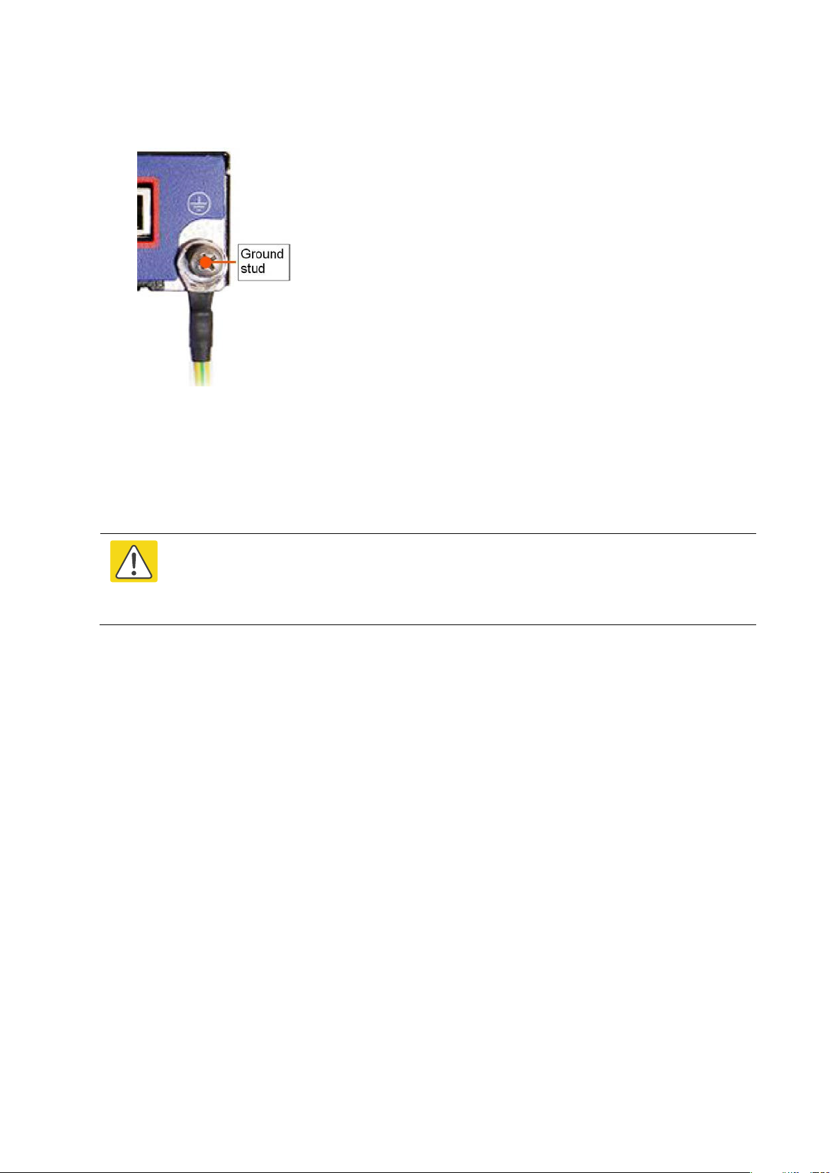
Use a grounding cable to connect the ground stud of the PTP-SYNC to the master ground bar of
the building, or to the rack ground bar.
Powering up the PTP-SYNC installation
Use this procedure to power up the PTP-SYNC installation.
Ensure that all cables are connected to the correct interfaces of the PTP SYNC unit and
the GPS receiver (if used). Ensure that the installation is correctly grounded Failure to
do so may result in damage to the equipment.
Connect the power supply to the PSU.
Within 90 seconds, the PTP-SYNC STATUS LED should blink once every second to show that
satellite lock has been achieved.
If the system does not operate correctly, refer to Testing PTP-SYNC on page 8-15.
Page 5-29
Page 30

Chapter 5: Installation Installing a GPS receiver
Caution
Caution
1
2
3
Installing a GPS receiver
To install a GPS receiver as the timing reference source for PTP-SYNC, use the following
procedures:
• Mounting the GPS receiver on page 5-30
• Preparing the GPS drop cable on page 5-30
• Assembling an RJ45 plug and housing for GPS on page 5-31
• Assembling a 12 way circular connector on page 5-33
• Connecting the GPS drop cable on page 5-37
• Top grounding point for GPS adapter cable on page 5-38
• Installing and connecting the GPS LPU on page 5-39
Prior to power-up of equipment, ensure that all cables are connected to the correct
interfaces of the PTP-SYNC unit and the GPS receiver module. Failure to do so may
result in damage to the equipment.
Mounting the GPS receiver
Mount the GPS receiver (following manufacturer’s instructions) upon either an external wall
(Figure 43) or a metal tower or mast (Figure 44).
Preparing the GPS drop cable
Use this procedure to make the main drop cable that will connect the GPS receiver to its
bottom LPU. GPS drop cables do not require top LPUs.
Always use Cat5e cable that is gel-filled and shielded with copper-plated steel.
Alternative types of cable are not supported by Cambium.
Measure the distance from the GPS receiver to the LPU site at building entry.
Cut the required length of drop cable.
Attach one or more hoisting grips to the top end of the cable, as described in Install the main drop
cable on page 5-18.
Page 5-30
Page 31
Chapter 5: Installation Installing a GPS receiver
4
5
Note
1
2
Fit a suitable GPS connector to the top end of the drop cable:
• If a GPS adapter cable kit is available, attach the plug housing and an RJ45 plug to the top end
of the main GPS drop cable, as described in Assembling an RJ45 plug and housing for GPS on
page 5-31.
• If a GPS adapter cable kit is not available, fit a 12 way circular connector to the top end of the
main drop cable as described in Assembling a 12 way circular connector on page 5-33.
Hoist the GPS drop cable safely up a tower or building, as described in Install the main drop cable.
on page
5-18.
Assembling an RJ45 plug and housing for GPS
Use this procedure to assemble the plug housing over the end of the drop cable. This
procedure is only performed when a GPS adapter cable kit is available. This kit is used to
connect the Trimble Acutime™ GG GPS receiver or the Trimble Acutime™ Gold GPS receiver
to the GPS drop cable.
The kit contains an adapter cable (GPS receiver circular connector to RJ45 socket) and an RJ45
plug housing. The plug housing should be assembled over the end of the drop cable to provide
a sealed connection to the adapter cable.
These instructions are for the preparation of the Cambium-supplied drop cable type
(Superior Essex BBDGE). Other types of cable may need different preparation
methods.
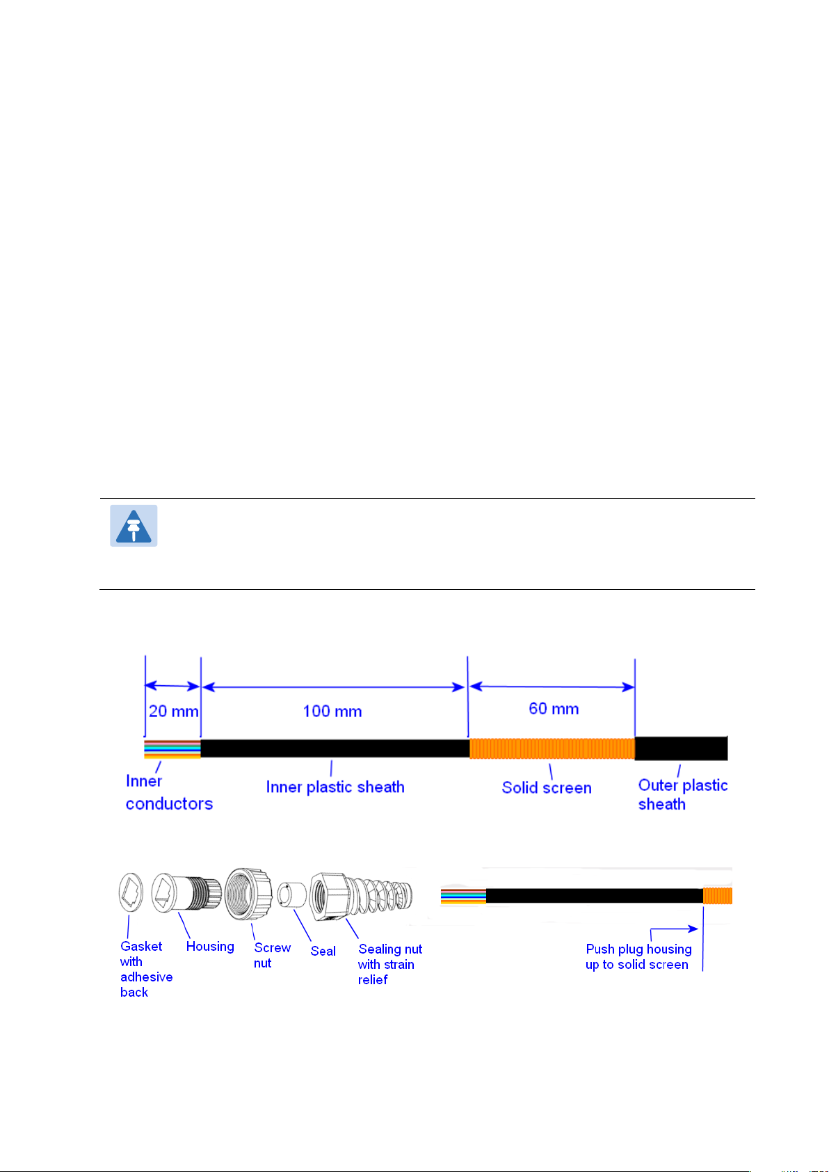
Prepare the top end of the GPS drop cable.
Install plug housing from the converter kit onto the prepared cable. Do not tighten the nuts at
this stage.
Page 5-31
Page 32
Chapter 5: Installation Installing a GPS receiver
3
4
5
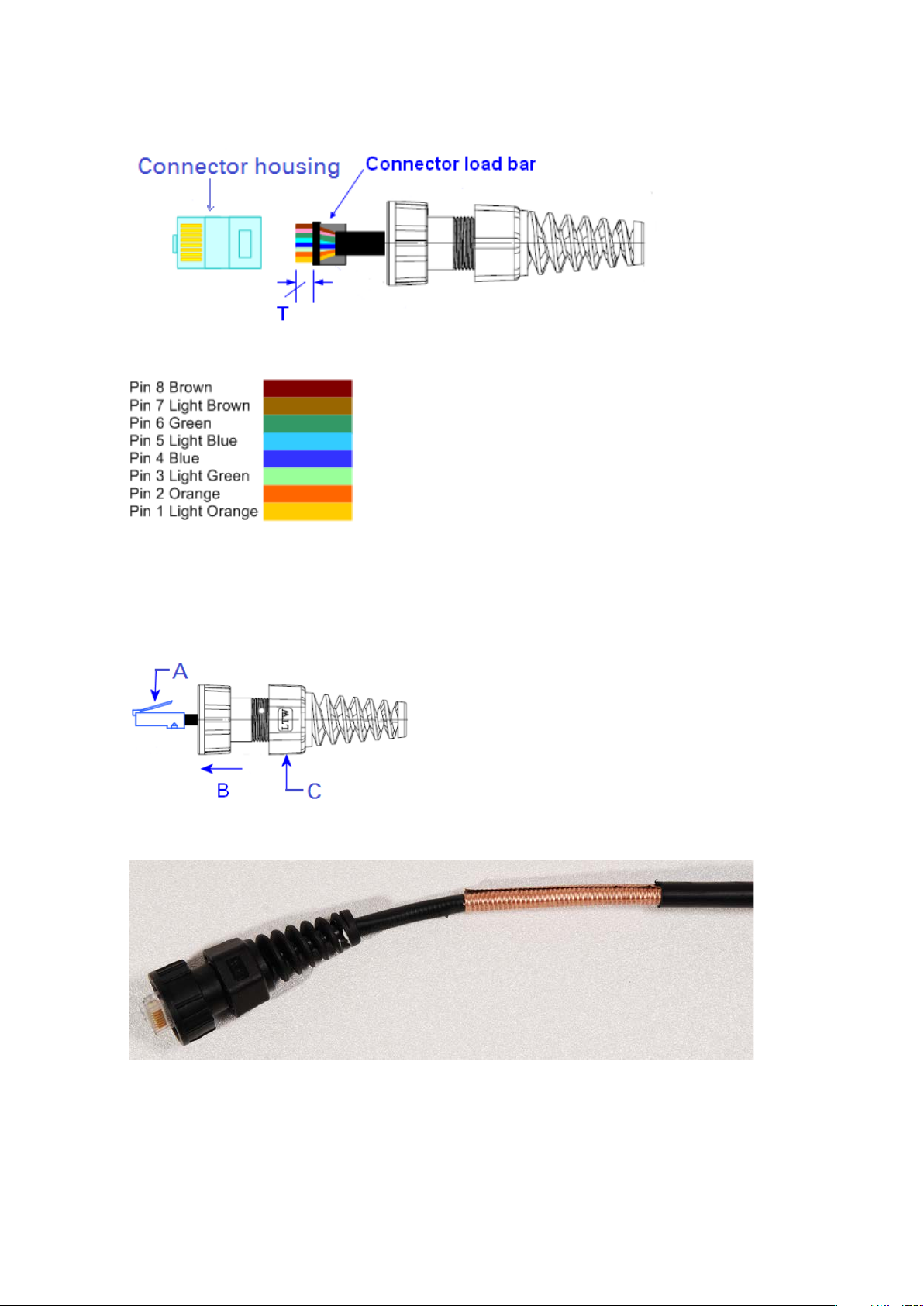
Install the RJ45 crimp plug.
Start with tails over-length to assist insertion into load bar, then trim them to 5 mm (T).
Connect the RJ45 pins to the following conductors (Superior Essex BBDGe colors):
Assemble plug housing:
Depress the RJ45 locking tab (A).
Slide the plug housing assembly (B) over the RJ45 plug.
Tighten the sealing nut (C). This is easier to fully tighten when the plug housing is mated
to the socket of the adapter cable.
Check the assembly. This is an exampled of an assembled plug housing on the end of a drop
cable:
Page 5-32
Page 33

Chapter 5: Installation Installing a GPS receiver
Note
This procedure requires a soldering iron and solder.
Caution
Table 114
GPS
connector
location
Function
Cat5e wire color
PTP-SYNC
(J10)
RJ45 pin
PTP-SYNC
signal
name
Conventional
Supported
drop cable
Assembling a 12 way circular connector
Use this procedure to connect the GPS drop cable to a 12 way circular connector. This
procedure is only performed when a GPS adapter cable kit is NOT available.
The drop cable has solid copper conductors. There are a limited number of times
each conductor can be bent before it fatigues and fails.
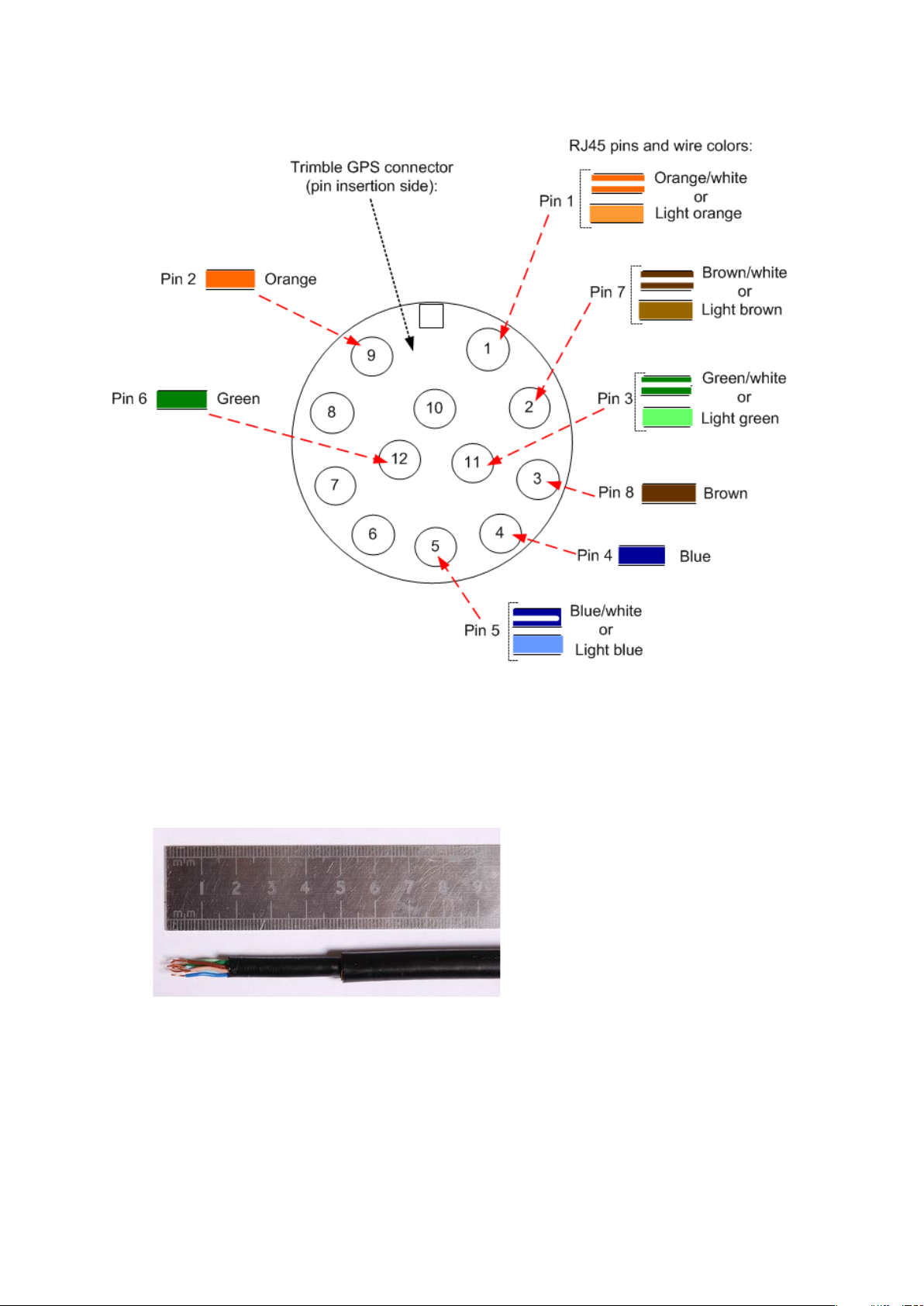
Table 114 shows how the 12 way circular connector locations map to the PTP-SYNC RJ45 pins.
Figure 114 illustrates this mapping.
1 DC Pwr (12V) Orange/White Light Orange 1 12VGPS
2 RxB- Brown/White Light Brown 7 GPS_TXDA
3 RxB+ Brown Brown 8 GPS_TXDB
4 TxB- Blue Blue 4 GPS_RXDA
5 TxB+ Blue/White Light Blue 5 GPS_RXDB
6 RxA- N.C N.C ---
7 RxA+ N.C N.C ---
8 TxA- N.C N.C ---
9 DC Ground Orange Orange 2 GND
10 TxA+ N.C N.C ---
11 Tx1PPS+ Green/White Light Green 3 GPS_1PPSA
GPS 12 way circular connector to RJ45 pin mappings
12 Tx1PPS- Green Green 6 GPS_1PPSB
Page 5-33
Page 34
Chapter 5: Installation Installing a GPS receiver
Figure 114
1
Inserting RJ45 pins into the 12 way circular connector
Prepare the drop cable end as follows:
• Bare back the cable outer and copper screen to 50mm.
• Bare back the cable inner to 17mm.
• Un-twist the cable pairs.
• Strip the individual conductors to 5mm.
Page 5-34
Page 35
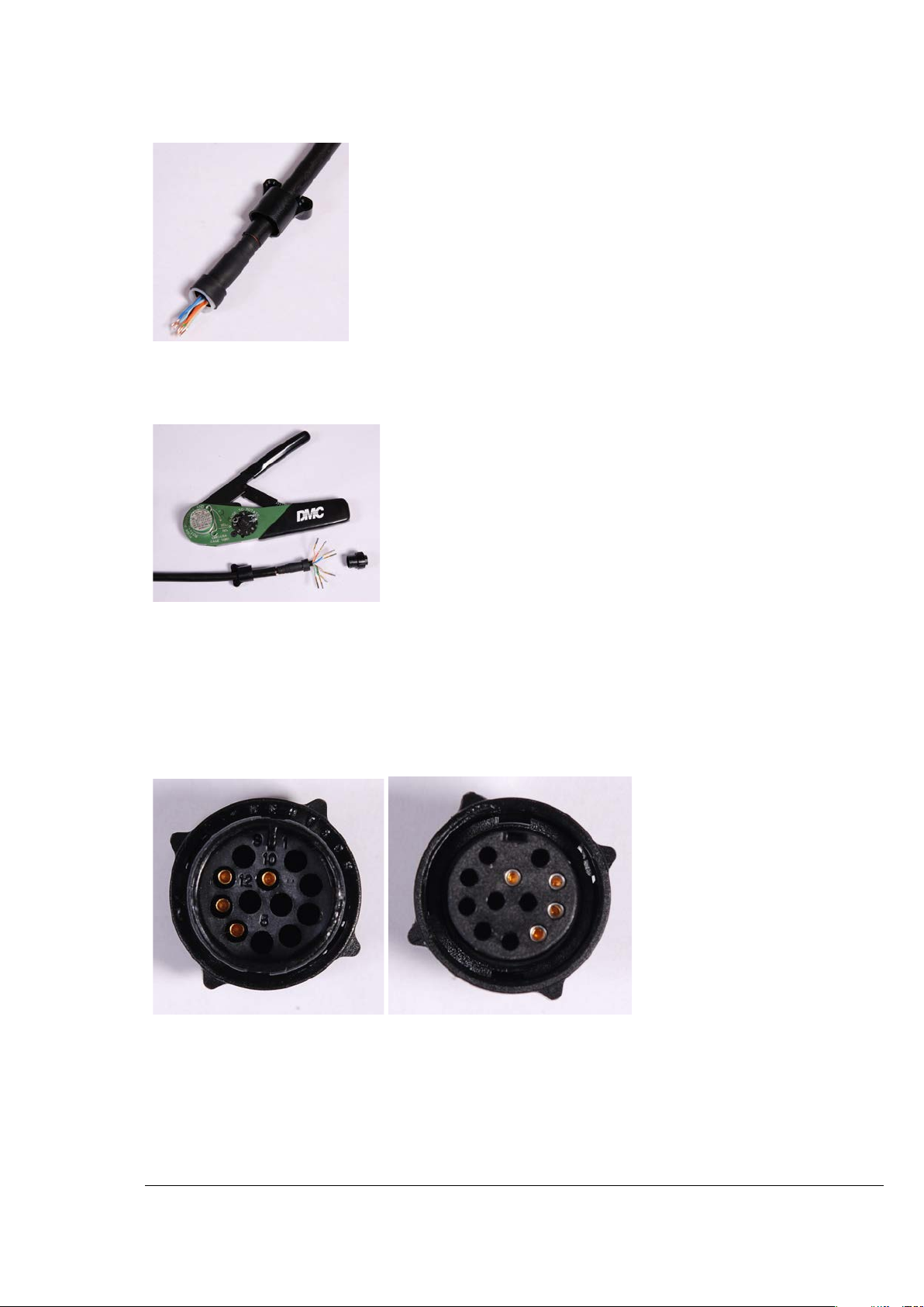
Chapter 5: Installation Installing a GPS receiver
2
3
Crimp
Solder
4
5
Fit the plug outer, associated boot, and boot insert.
Connect the socket contacts using either of the following techniques:
•
: Crimp the socket contacts onto each of the conductors using the correct crimp tool and
positioner, setting the wire size selector to “3” for 24AWG wire.
•
: When soldering the socket contacts onto each of the conductors, ensure that there is
no solder or flux residue on the outside of the contact. Care should also be taken that the
individual conductor insulation does not peel back with the soldering heat, allowing possible
shorts when assembled into the plug shell.
Fit four dummy contacts into the unused 12 way circular connector locations (6, 7, 8 and 10), to
provide strength and sealing. Push the contacts in from the pin insertion side.
Pin insertion side: Plug mating side:
Insert the eight RJ45 contact pins into the pin insertion side of the 12 way circular connector in
accordance with Figure 114.
It is easiest to insert the pins from the center out, in descending order of Trimble location number,
that is, 12, 11, 9, 5, 4, 3, 2, 1. Push the contacts in so that the shoulder on the contact fits into the
hole in the plug shell. When all contacts have been fitted, push them in further to engage with the
locking mechanism in the plug shell. This can be done by applying pressure to the contact with a
small diameter stiff object, such as tweezers.
Page 5-35
Page 36
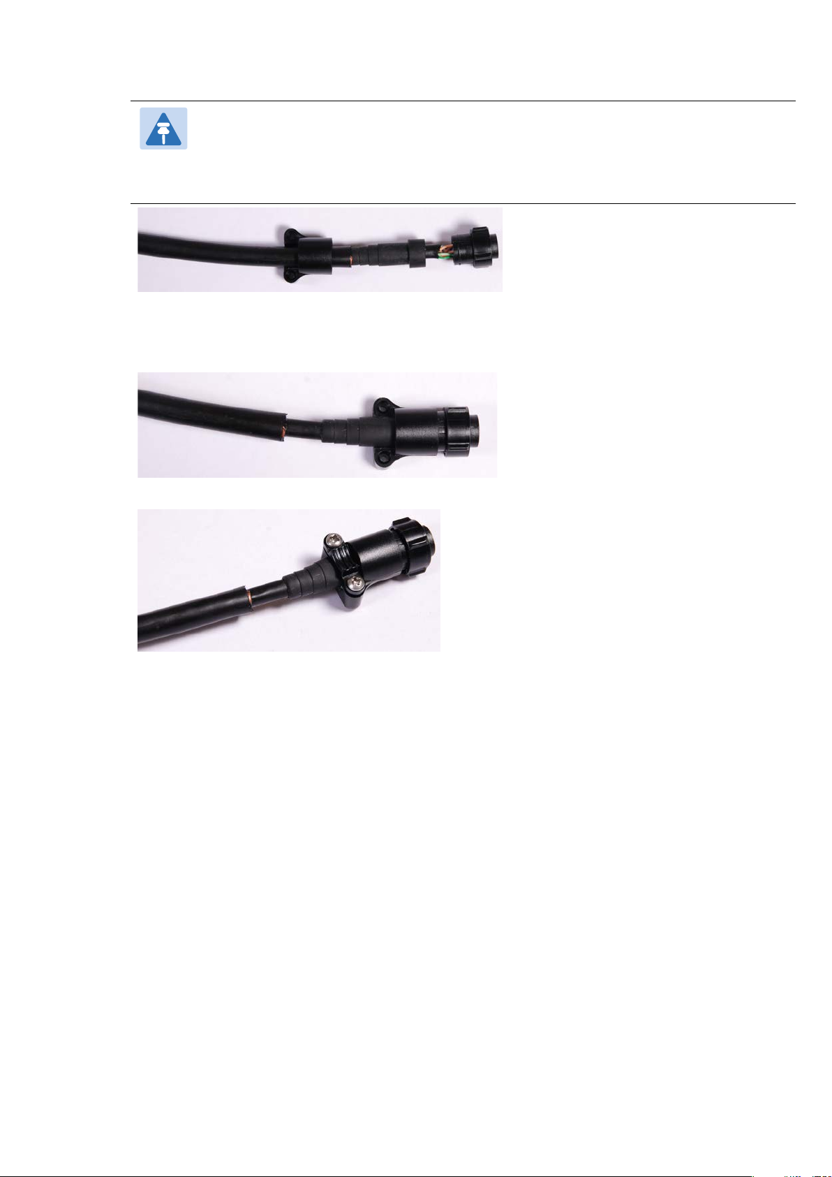
Chapter 5: Installation Installing a GPS receiver
Note
6
7
If a contact is pushed in to the point where the locking mechanism engages before all
of the contacts have been inserted it will limit the amount of room available to fit the
remaining contacts, requiring harder bends to be applied.
Fit the plug to its shell. The plastic ring fits inside the rubber boot and ensures a tight fit when the
plug body is clipped onto the plug shell. Be aware that the plug body is a hard push fit onto the
plug shell.
Fit the strain relief clip.
Page 5-36
Page 37
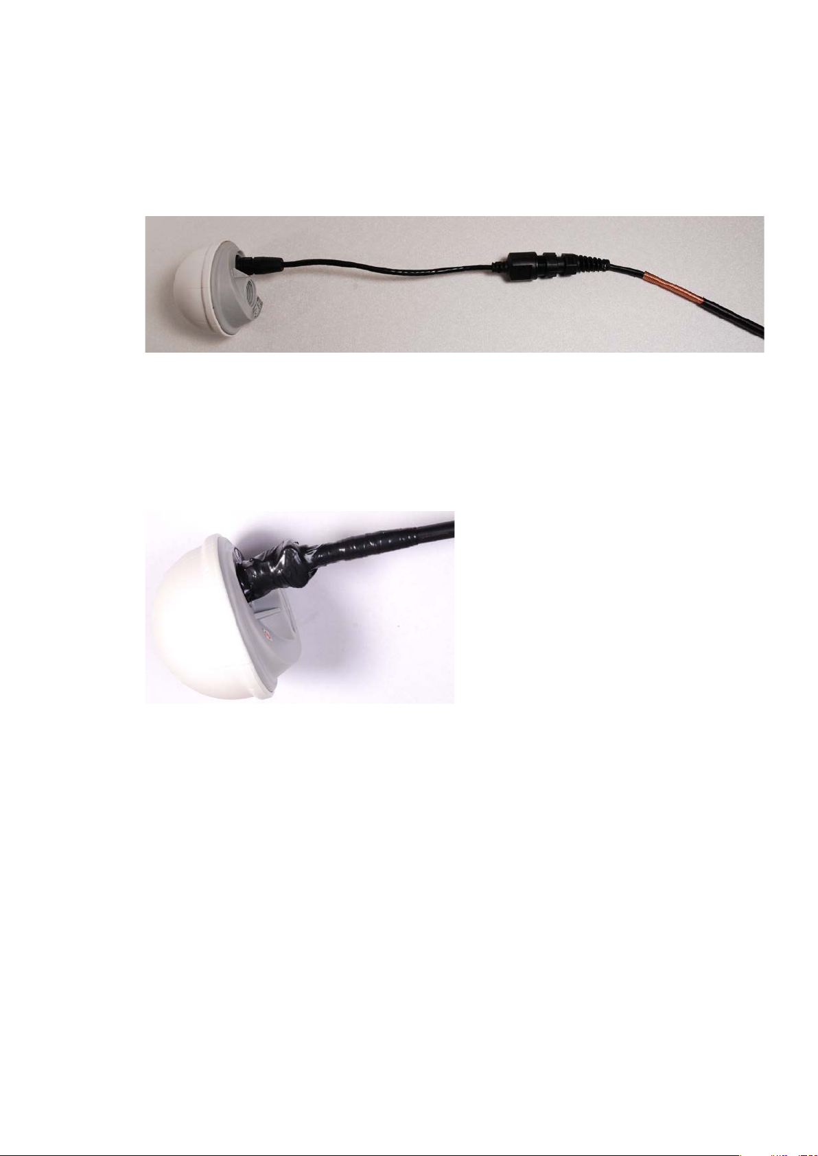
Chapter 5: Installation Installing a GPS receiver
1
2
3
4
5
Connecting the GPS drop cable
Use this procedure to connect the GPS drop cable to the GPS unit and supporting structure.
If a GPS adapter cable is available, use it to connect the main GPS drop cable to the GPS unit:
If a GPS adapter cable is not available, connect the main GPS drop cable to the GPS unit via a 12
way circular connector. Weatherproof the connection as follows:
• Wrap a layer of self-amalgamating tape, starting 25mm below the bared back outer of the
cable and finishing at the GPS housing.
• Wrap a layer of PVC tape, starting just below the start of the self-amalgamating tape and
finishing at the GPS housing, overlapping at half width.
• Repeat with four more layers of PVC tape alternating the start and finish ends.
Lay the main drop cable as far as the building entry point, ensuring there is enough length to
extend through the wall of the building to the LPU.
Attach the main GPS drop cable to the supporting structure using site approved methods.
Ground the GPS drop cable to the supporting structure at the points shown in Figure 43 (wall
installation) or Figure 44 (mast or tower installation):
• For standard grounding instructions, see Creating a drop cable grounding point on page 5-
57.
• If a GPS adapter cable has been installed, see Top grounding point for GPS adapter cable on
page 5-38.
Page 5-37
Page 38
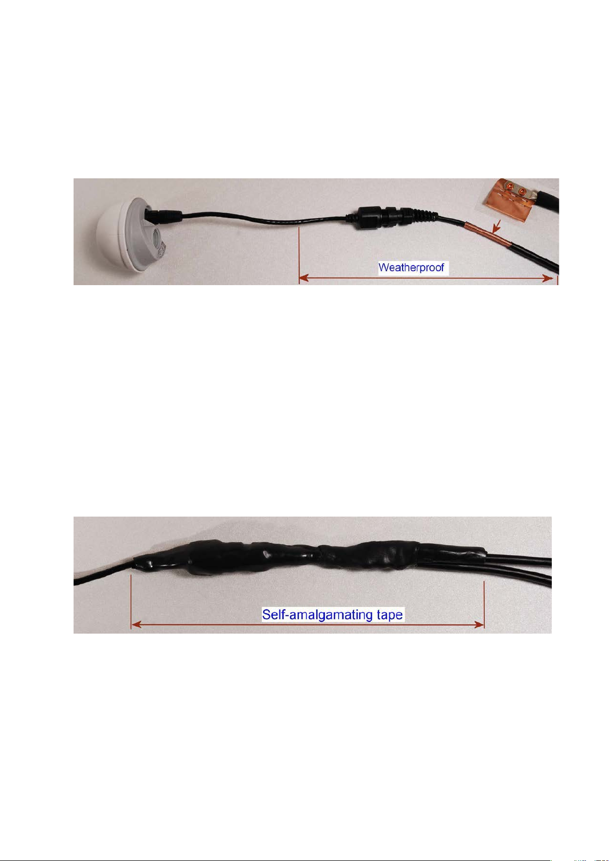
Chapter 5: Installation Installing a GPS receiver
Figure 115
Figure 116
Top grounding point for GPS adapter cable
If a GPS adapter cable has been installed (Figure 115), use this procedure to ground the drop
cable at the point where the solid screen is already exposed, and weatherproof both the
ground cable joint and the RJ45 connection.
Follow the procedure described in Creating a drop cable grounding point on page 5-57, but
observe the following differences:
• There is no need to remove 60mm (2.5inches) of the drop cable outer sheath, as this has
already been done.
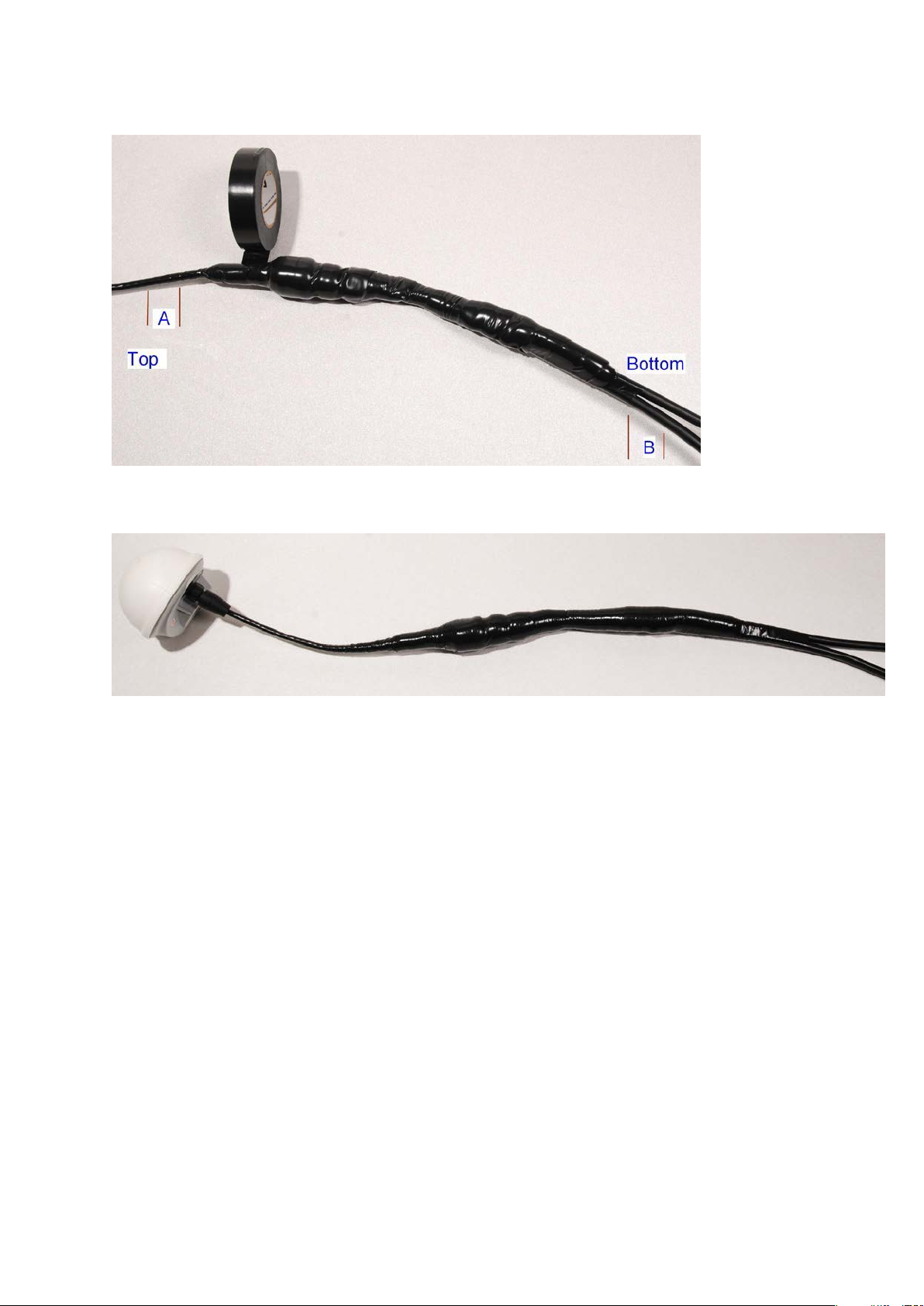
• Wrap the top layer of self-amalgamating tape around the complete assembly (not just the
ground cable joint), including the RJ45 connection with the GPS adapter cable (Figure 116).
• Wrap all five layers of PVC tape around the complete assembly (Figure 117). Wrap the
layers in alternate directions: (1st) bottom to top; (2nd) top to bottom; (3rd) bottom to top;
(4th) top to bottom; (5th) bottom to top. The edges of each layer should be 25mm (1 inch)
above (A) and 25 mm (1 inch) below (B) the previous layer.
• Check that the joint between the GPS adapter cable, drop cable and ground cable is fully
weatherproofed (Figure 118).
Grounding and weatherproofing requirements for GPS adapter cable
Wrapping self-amalgamating tape around the GPS adapter cable joint
Page 5-38
Page 39
Chapter 5: Installation Installing a GPS receiver
Figure 117
Figure 118
Wrapping PVC tape around the GPS adapter cable joint
Grounding and weatherproofing example for GPS adapter cable
Installing and connecting the GPS LPU
Install and ground the GPS drop cable LPU at the building (or cabinet) entry point, and install
the LPU-PTP-SYNC drop cable, as described in Install the bottom LPU on page 5-21.
Connect this cable to the PTP-SYNC unit as described in Connecting up the PTP-SYNC unit on
page 5-27.
Page 5-39
Page 40
Chapter 5: Installation Installing a NIDU
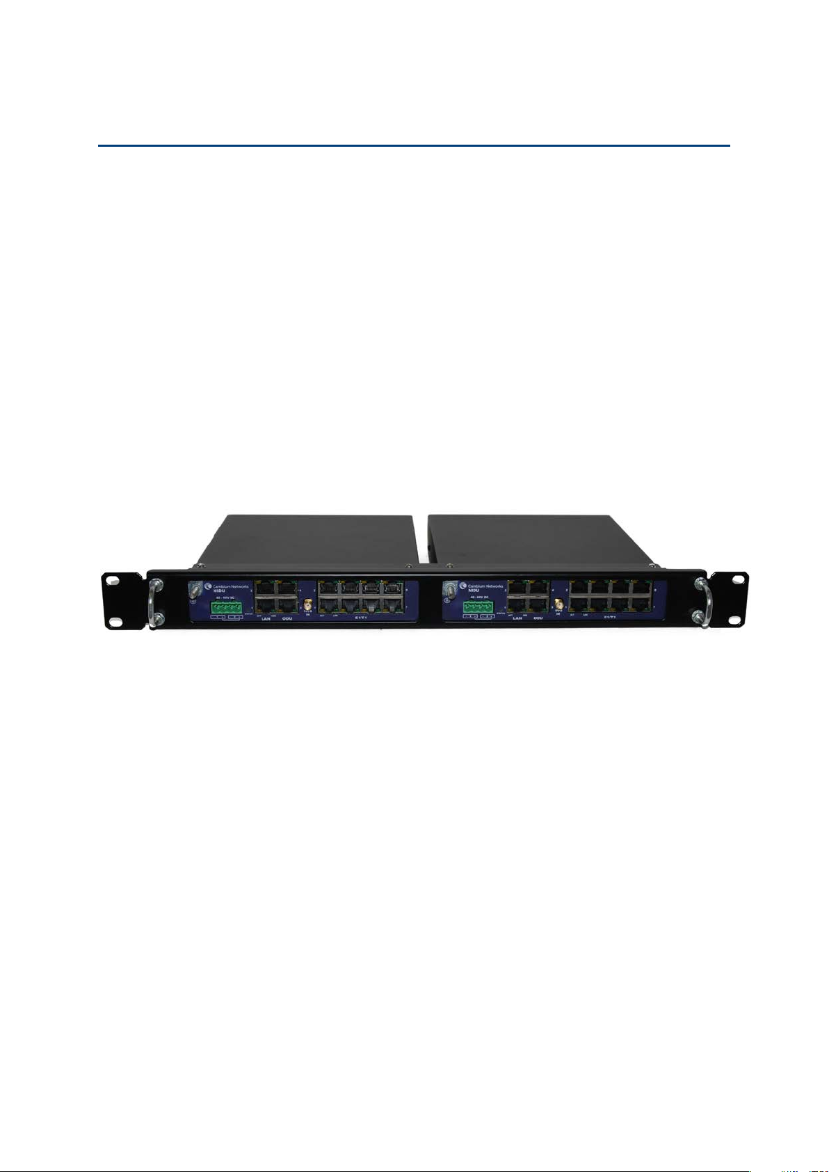
Figure 119
Installing a NIDU
To install a NIDU (for TDM), use the following procedures:
• Mounting the NIDU on page 5-40
• Connecting the NIDU to the PSU, LAN and TDM cables on page 5-41
• Connecting the NIDU to a DC power supply on page 5-43
Mounting the NIDU
Mount the NIDU in the equipment building, either in a rack or on a horizontal surface:
• Racking mounting option: fix the NIDU to the rack mount using the M3 screws from the
rack mount installation kit (Figure 119). The rack can hold either two NIDUs or one NIDU
and one PTP-SYNC unit.
• Horizontal option: place the NIDU on a horizontal surface.
Two NIDUs mounted in a rack
Page 5-40
Page 41
Chapter 5: Installation Installing a NIDU
Caution
Caution
Note
1
2
3
Connecting the NIDU to the PSU, LAN and TDM cables
Always connect the NIDU to the Main PSU port of the ODU via the PSU. The TDM service
will not operate if the NIDU is connected to the Aux or SFP port of the ODU.
If the ODU port has negotiated a link at 100BASE-T, the NIDU will not send or receive TDM
data and will not bridge customer data traffic. Ensure that the Ethernet drop cable between
the ODU and the PSU, and the network cable between the PSU and the NIDU, will reliably
support operation at 1000BASE-T.
Use the E1/T1 ports in ascending numeric sequence, for example: if there is one E1/T1
channel, use port 1; if are three E1/T1 channels, use ports 1, 2 and 3.
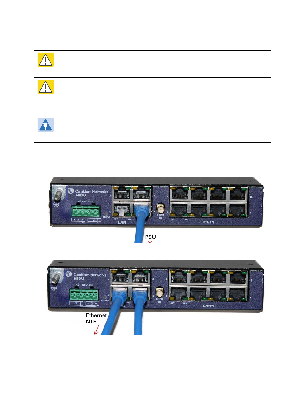
Use this procedure to connect the NIDU to the PSU, LAN and TDM transceivers.
Disconnect the power supply from the PSU.
Connect an indoor Cat5e cable from the NIDU (ODU port 3) to the PSU (LAN port):
Connect an indoor Cat5e cable from the NIDU (LAN port 1) to the Ethernet network terminating
equipment:
Page 5-41
Page 42
Chapter 5: Installation Installing a NIDU
4
5
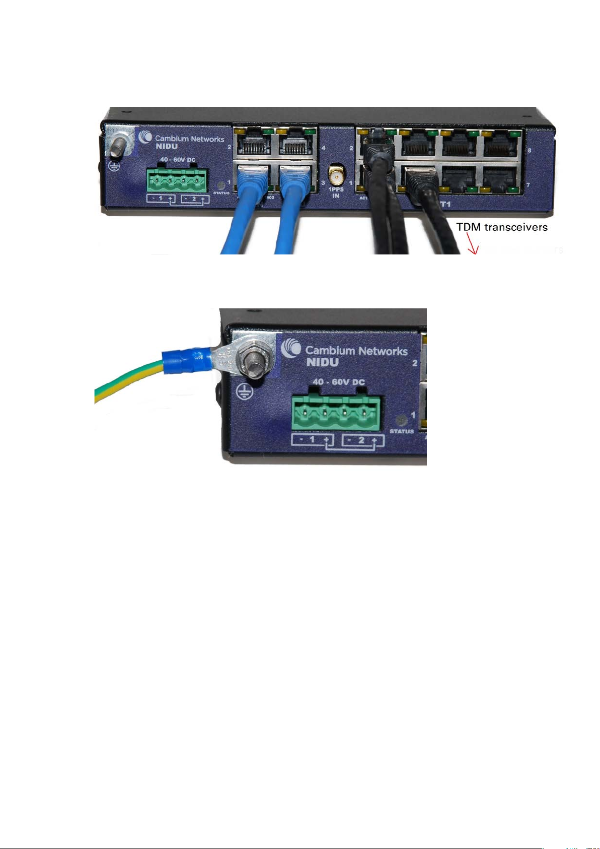
Connect up to eight indoor Cat5e cables (with RJ48 connectors) from the NIDU (E1/T1 ports) to the
local TDM transceivers:
Use an M5 nut and washer to connect the grounding cable lug to the NIDU ground bolt. Connect
the other end of the grounding cable to the master ground bar of the building or rack.
Page 5-42
Page 43
Chapter 5: Installation Installing a NIDU
Caution
Figure 120
Connecting the NIDU to a DC power supply
Do not power up the NIDU until site installation is complete, otherwise equipment
may be damaged.
Main and backup DC supplies
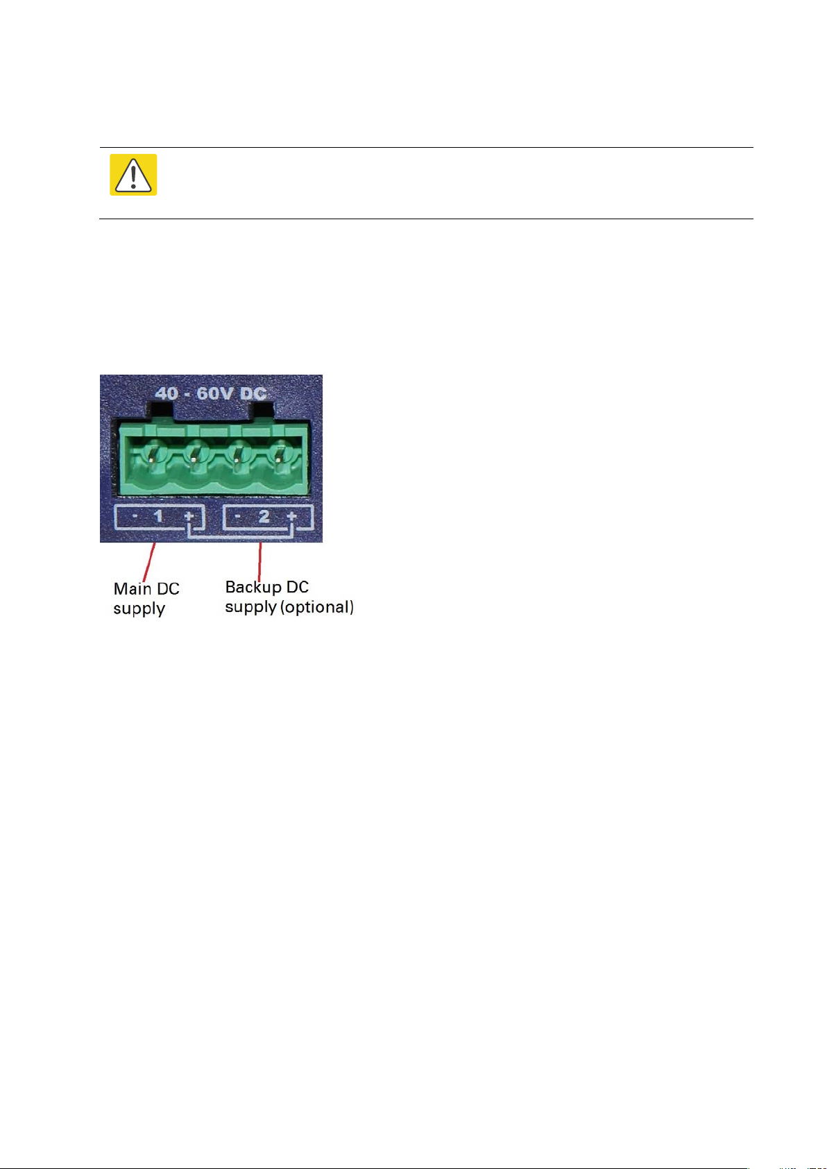
The NIDU requires a 40 V – 60 V DC power supply. The NIDU DC interface provides inputs for a
main and a backup DC power supply (Figure 120). The main DC supply (port 1) is mandatory,
but the backup (port 2) is optional.
NIDU DC interface
Use one of the following power supply options for the NIDU:
• The PTP 700 AC+DC Enhanced Power Injector (Cambium part number C000065L002) with
optional backup.
• An independent DC supply (if available) with optional backup.
• The PTP 800 AC-DC Power Supply Converter (Cambium part number WB3622).
Page 5-43
Page 44
Chapter 5: Installation Installing a NIDU
1
2
Using the DC power connector
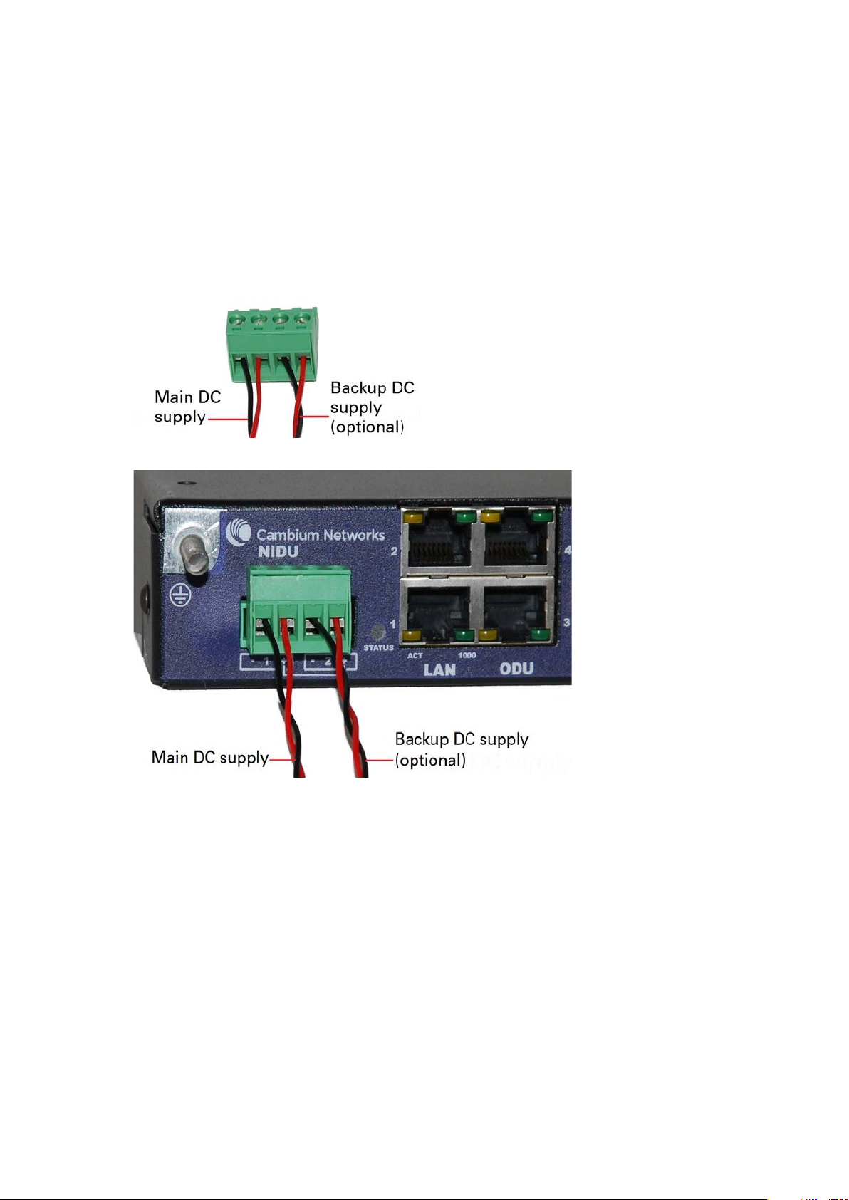
Use this procedure to connect the NIDU to the PTP 650/700 AC+DC Enhanced Power Injector
(Cambium part number C000065L002) or to an independent DC supply with an optional backup
DC supply:
Strip the two wires of the main DC supply cable and screw them into the first and second terminals
of the DC power connector (Cambium part number C000065L044). The first terminal is negative
(black wire) and the second is positive (red wire). If a backup supply is required, use the third and
fourth terminals of the connector:
Plug the DC power connector into the NIDU DC interface:
Page 5-44
Page 45
Chapter 5: Installation Installing a NIDU
3
4
Figure 121
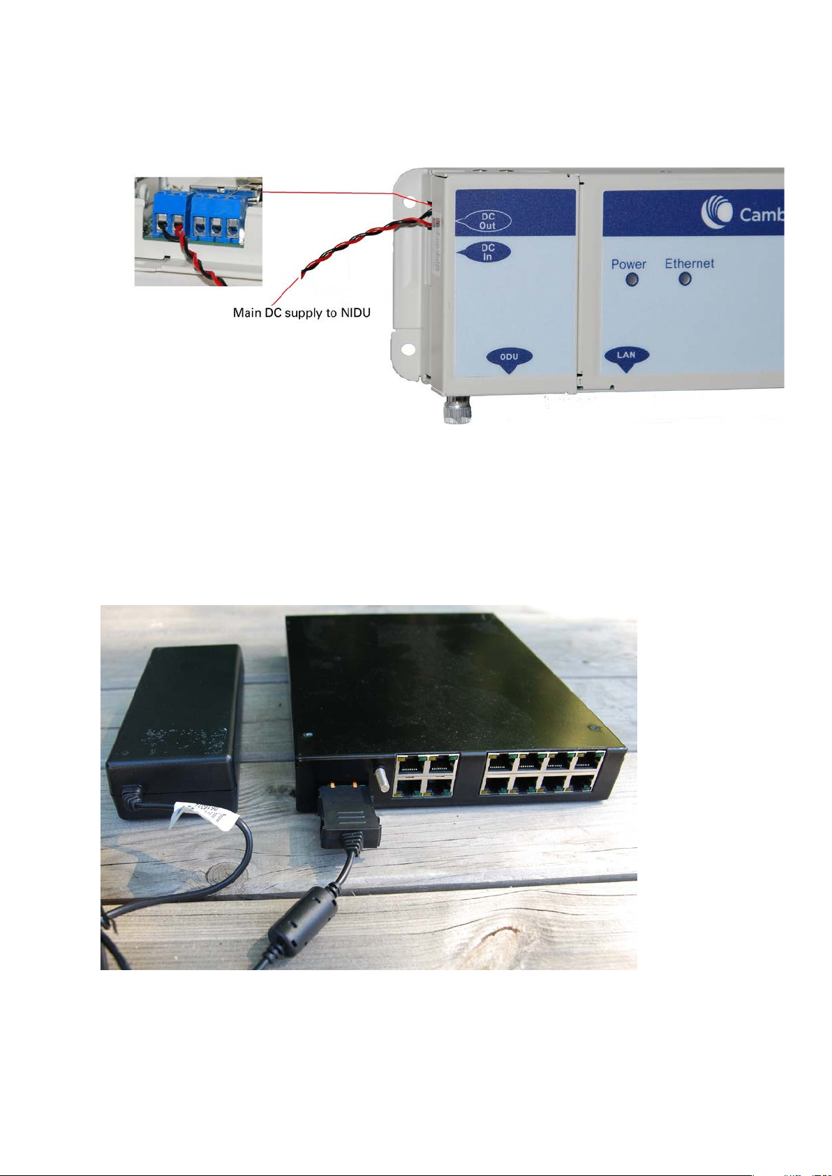
Connect the main DC supply cable to its power source. If this supply is from the AC+DC Enhanced
Power Injector, the DC Out first terminal is negative (black wire) and the second is positive (red
wire):
Connect the backup DC supply cable to its power source.
Using the PTP 800 AC-DC Power Supply Converter
If a suitable AC mains supply is available, use the PTP 800 AC-DC Power Supply Converter
(Cambium part number WB3622) to power the NIDU (Figure 121). This includes a DC power
connector that plugs into both ports of the NIDU DC interface.
NIDU powered by the PTP 800 AC-DC Power Supply Converter
Page 5-45
Page 46

Chapter 5: Installation Installing an SFP Ethernet interface
Installing an SFP Ethernet interface
In more advanced configurations, there may be an optical or copper Cat5e Ethernet interface
connected to the SFP port of the ODU. Refer to Typical deployment on page 3-2 for diagrams of
these configurations.
Adapt the installation procedures in this chapter as appropriate for SFP interfaces, noting the
following differences from a PSU interface:
• Install an optical or copper SFP module in the ODU (SFP port) and connect the SFP optical
or copper cable into this module using the long cable gland from the SFP module kit. This
is described in the following procedures:
o Fitting the long cable gland on page 5-48
o Inserting the SFP module on page 5-49
o Connecting the cable on page 5-51
o Fitting the gland on page 5-52
o Removing the cable and SFP module on page 5-54
• Optical cables do not require LPUs or ground cables.
• At the remote end of an SFP drop cable, use an appropriate termination for the connected
device.
• If the connected device is outdoors, not in the equipment building or cabinet, adapt the
grounding instructions as appropriate.
• PTP 700 LPUs are not suitable for installation on SFP copper Cat5e interfaces. For SFP drop
cables, obtain suitable surge protectors from a specialist supplier.
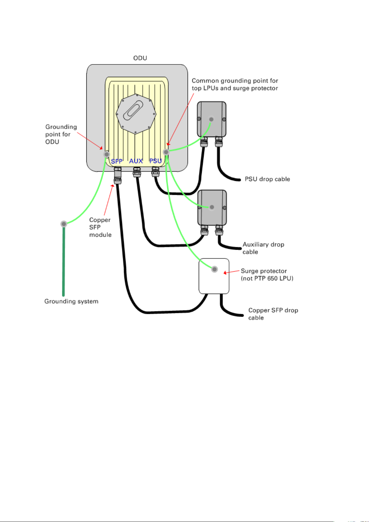
• Ground the top LPUs and surge protector to the same point on the ODU (Figure 122).
Page 5-46
Page 47
Chapter 5: Installation Installing an SFP Ethernet interface
Figure 122
ODU with copper Cat5e connections to all three Ethernet ports
Page 5-47
Page 48
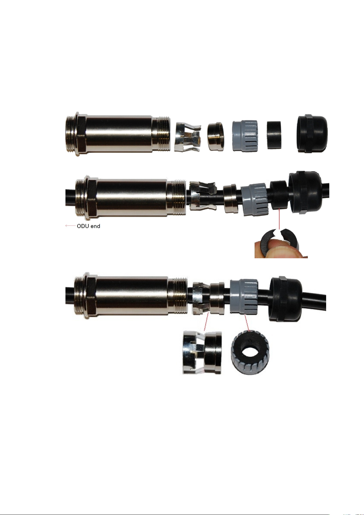
Chapter 5: Installation Installing an SFP Ethernet interface
Optical SFP interface
Copper Cat5e SFP interface
1
2
3
Fitting the long cable gland
connector at the ODU end as shown below.
the RJ45 connector at the ODU end as shown below.
Disassemble the gland:
Thread each part onto the cable (the rubber bung is split):
: Disassemble the long cable gland and thread its components over the LC
: Disassemble the long cable gland and thread its components over
Assemble the spring clip and the rubber bung (the clips go inside the ring):
Page 5-48
Page 49
Chapter 5: Installation Installing an SFP Ethernet interface
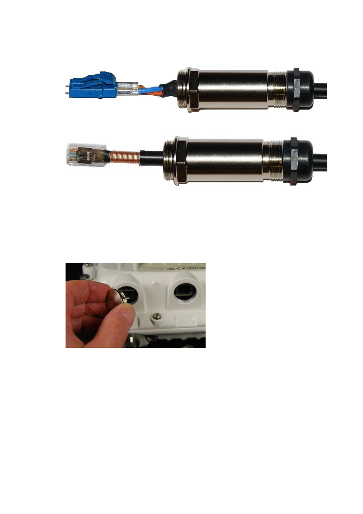
4
1
Fit the parts into the body and lightly screw on the gland nut (do not tighten it):
Optical
Copper
Inserting the SFP module
To insert the SFP module into the ODU, proceed as follows:
Remove the blanking plug from the SFP port of the ODU:
Page 5-49
Page 50
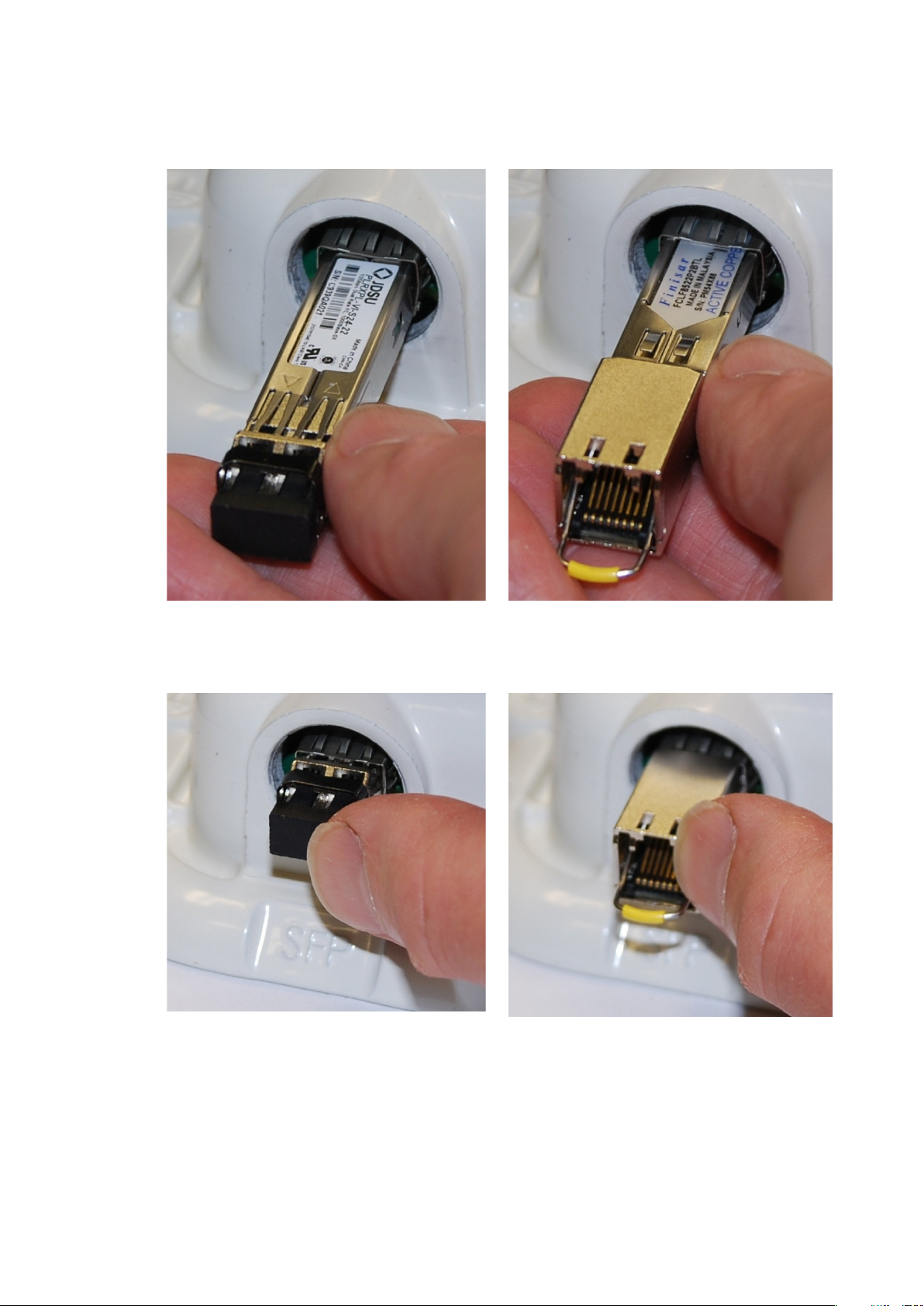
Chapter 5: Installation Installing an SFP Ethernet interface
2
3
Insert the SFP module into the SFP receptacle with the label up:
Optical
Copper
Push the module home until it clicks into place:
Optical
Copper
Page 5-50
Page 51
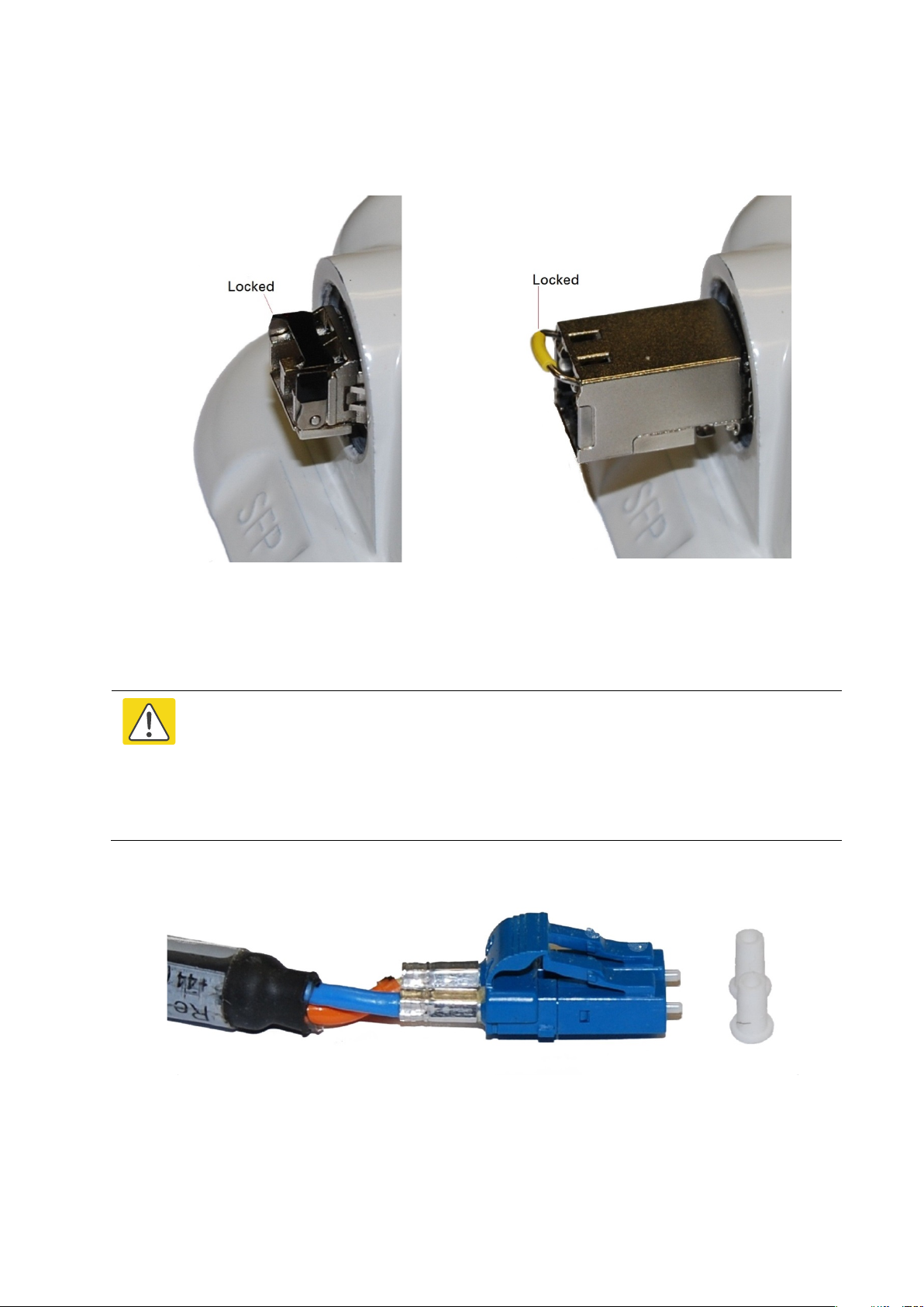
Chapter 5: Installation Installing an SFP Ethernet interface
4
Caution
1
2
Rotate the latch to the locked position:
Optical
Copper
Connecting the cable
The fiber optic cable assembly is very delicate. To avoid damage, handle it with
extreme care. Ensure that the fiber optic cable does not twist during assembly,
especially when fitting and tightening the weatherproofing gland.
Do not insert the power over Ethernet drop cable from the PSU into the SFP module,
as this will damage the module.
Remove the LC connector dust caps from the ODU end (optical cable only):
Plug the connector into the SFP module, ensuring that it snaps home:
Page 5-51
Page 52
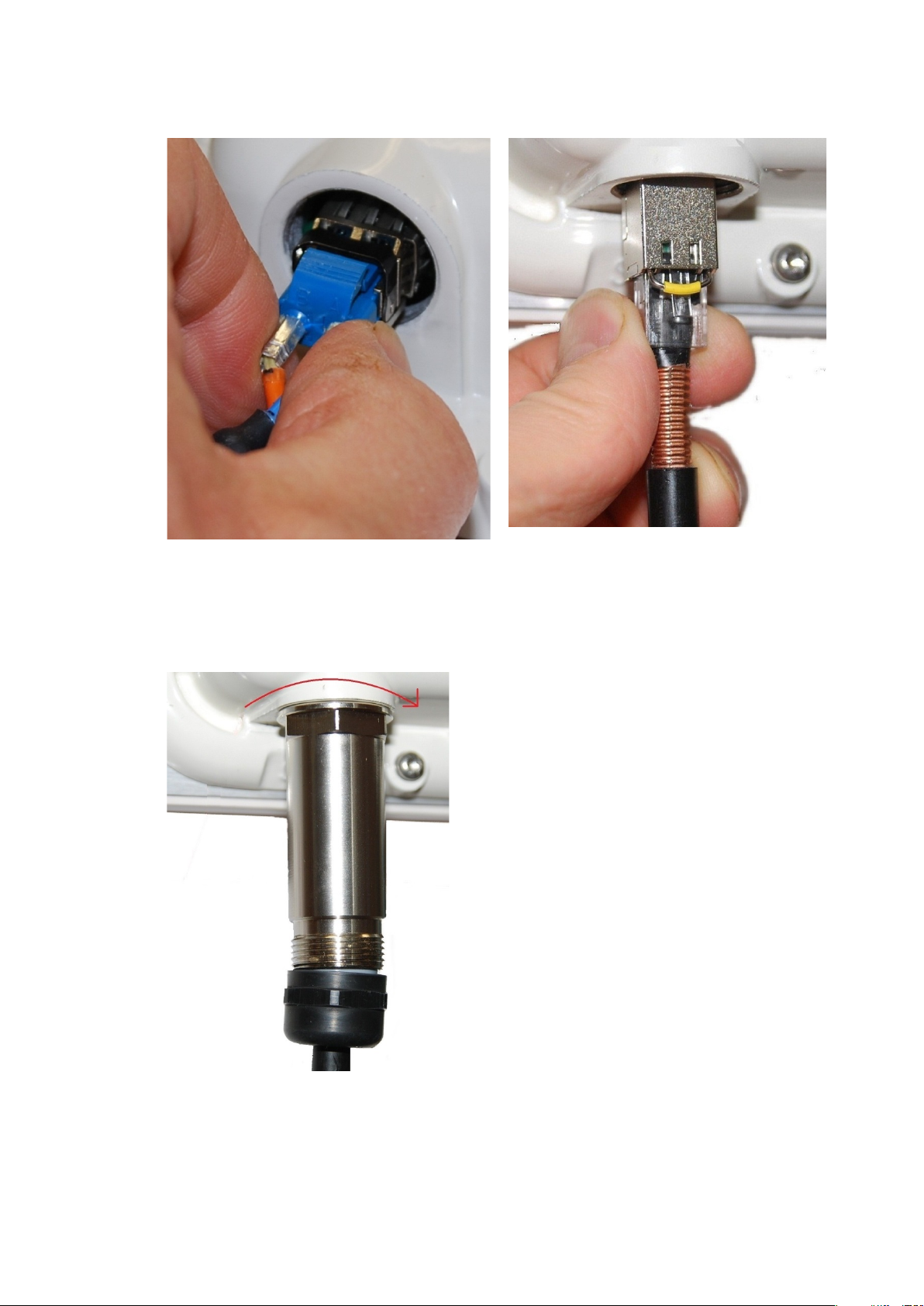
Chapter 5: Installation Installing an SFP Ethernet interface
1
2
Optical
Copper
Fitting the gland
Fit the gland body to the SFP port and tighten it to a torque of 5.5 Nm (4.3 lb ft)
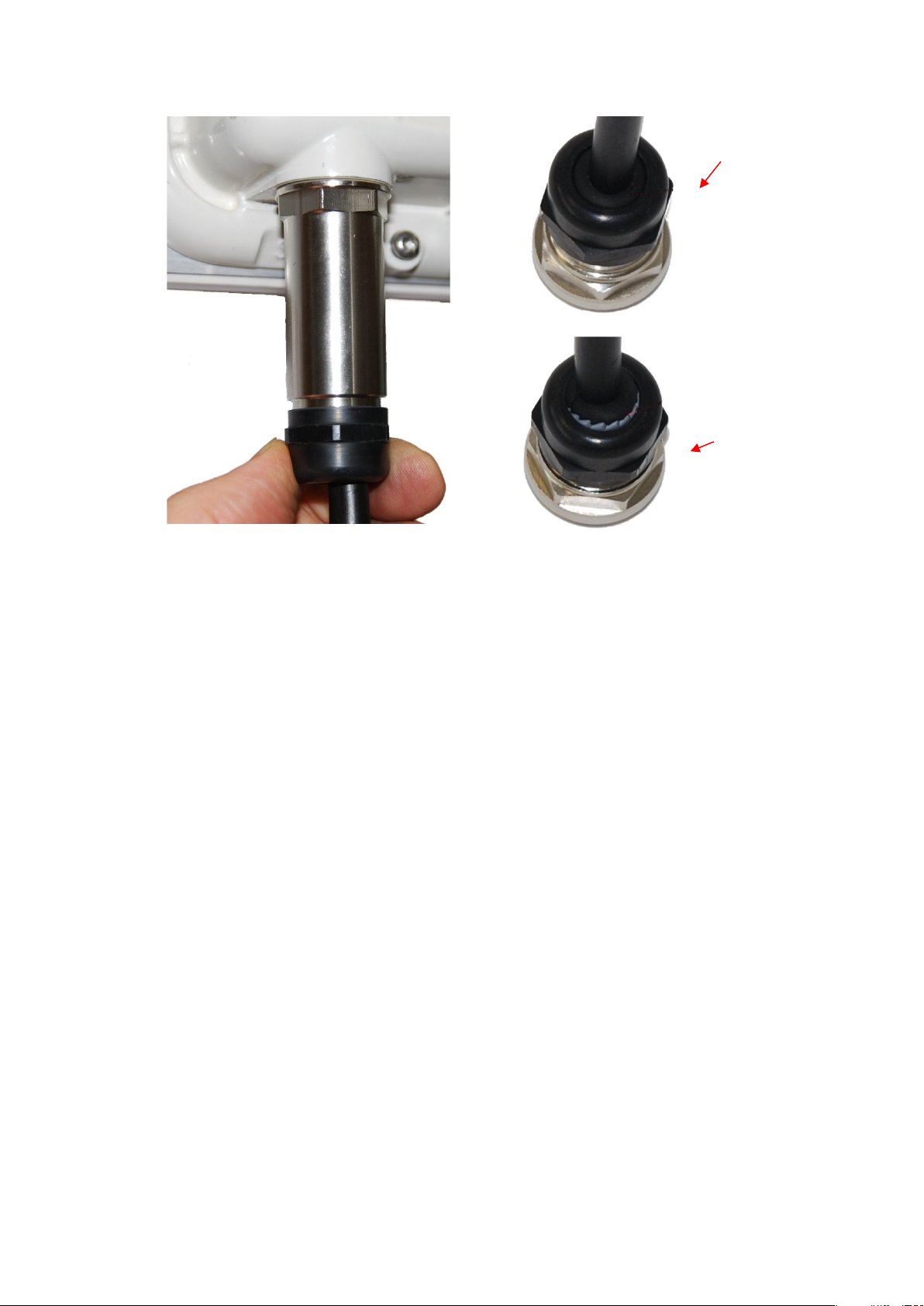
Fit the gland nut and tighten until the rubber seal closes on the cable. Do not over-tighten
the gland nut, as there is a risk of damage to its internal components:
Page 5-52
Page 53
Chapter 5: Installation Installing an SFP Ethernet interface
Correct
Incorrect
Page 5-53
Page 54
Chapter 5: Installation Installing an SFP Ethernet interface
1
2
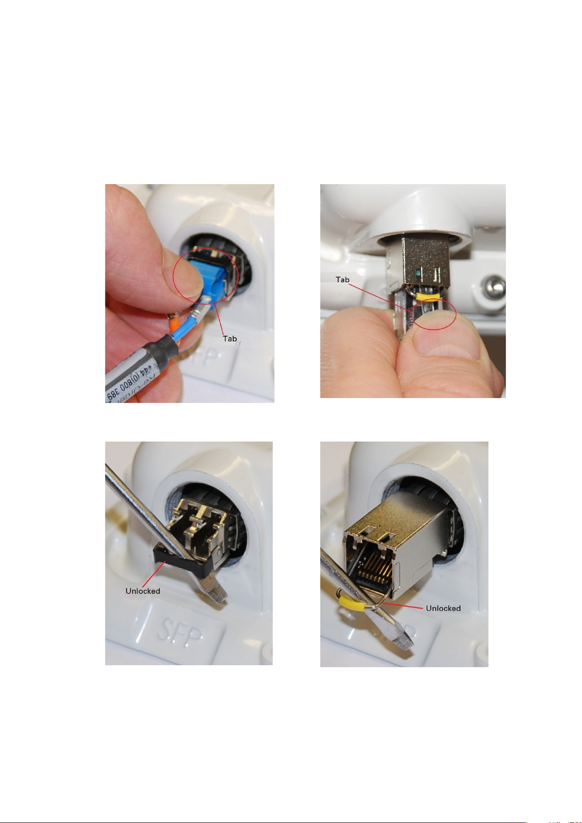
Removing the cable and SFP module
Do not attempt to remove the module without disconnecting the cable, otherwise the locking
mechanism in the ODU will be damaged.
Remove the cable connector by pressing its release tab before pulling it out:
Optical
Rotate the latch to the unlocked position. Extract the module by using a screwdriver:
Optical
Copper
Copper
Page 5-54
Page 55

Chapter 5: Installation Installing an Aux Ethernet interface
Installing an Aux Ethernet interface
In more advanced configurations, there may be a copper Cat5e Ethernet interface connected to
the Aux port of the ODU. Refer to Typical deployment on page 3-2 for a diagram of this
configuration.
Adapt the installation procedures in this chapter as appropriate for the Aux interface, noting
the following differences:
• At the remote end of the Aux drop cable, use an appropriate termination for the connected
device (for example, a video camera or wireless access point).
• If the connected device is outdoors, not in the equipment building or cabinet, adapt the
grounding instructions as appropriate.
• Ground the top LPUs and surge protector to the same point on the ODU (Figure 122).
Page 5-55
Page 56
Chapter 5: Installation Supplemental installation information
Supplemental installation information
This section contains detailed installation procedures that are not included in the above topics,
such as how to strip cables, create grounding points and weatherproof connectors.
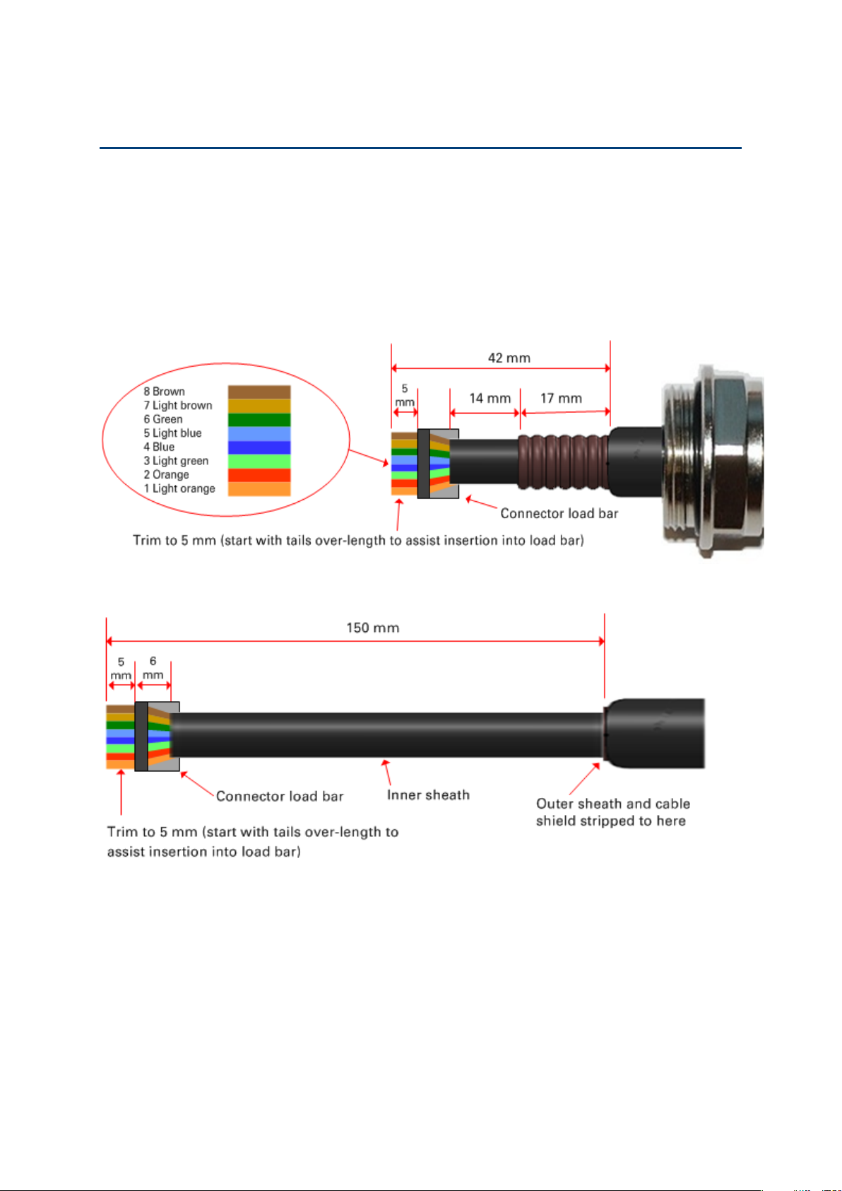
Stripping drop cable
When preparing drop cable for connection to the PTP 700 ODU or LPU, use the following
measurements:
When preparing drop cable for connection to the PTP 700 PSU (without a cable gland), use the
following measurements:
Page 5-56
Page 57
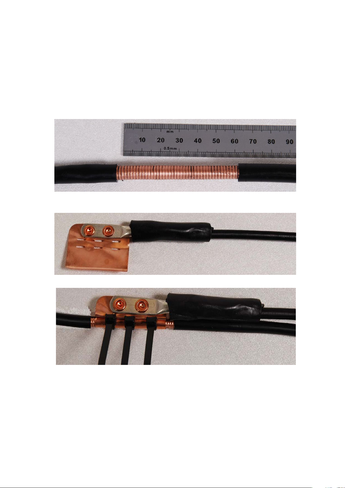
Chapter 5: Installation Supplemental installation information
1
Remove 60
2
Cut 38mm (1.5 inches) of rubber tape (
Wrap the tape completely around the lug and cable.
3
Fold the
Creating a drop cable grounding point
Use this procedure to connect the screen of the main drop cable to the metal of the supporting
structure using the cable grounding kit (Cambium part number 01010419001).
To identify suitable grounding points, refer to Drop cable grounding points on page 3-17.
mm (2.5 inches) of the drop cable outer sheath.
self-amalgamating) and fit to the ground cable lug.
ground wire strap around the drop cable screen and fit cable ties.
Page 5-57
Page 58
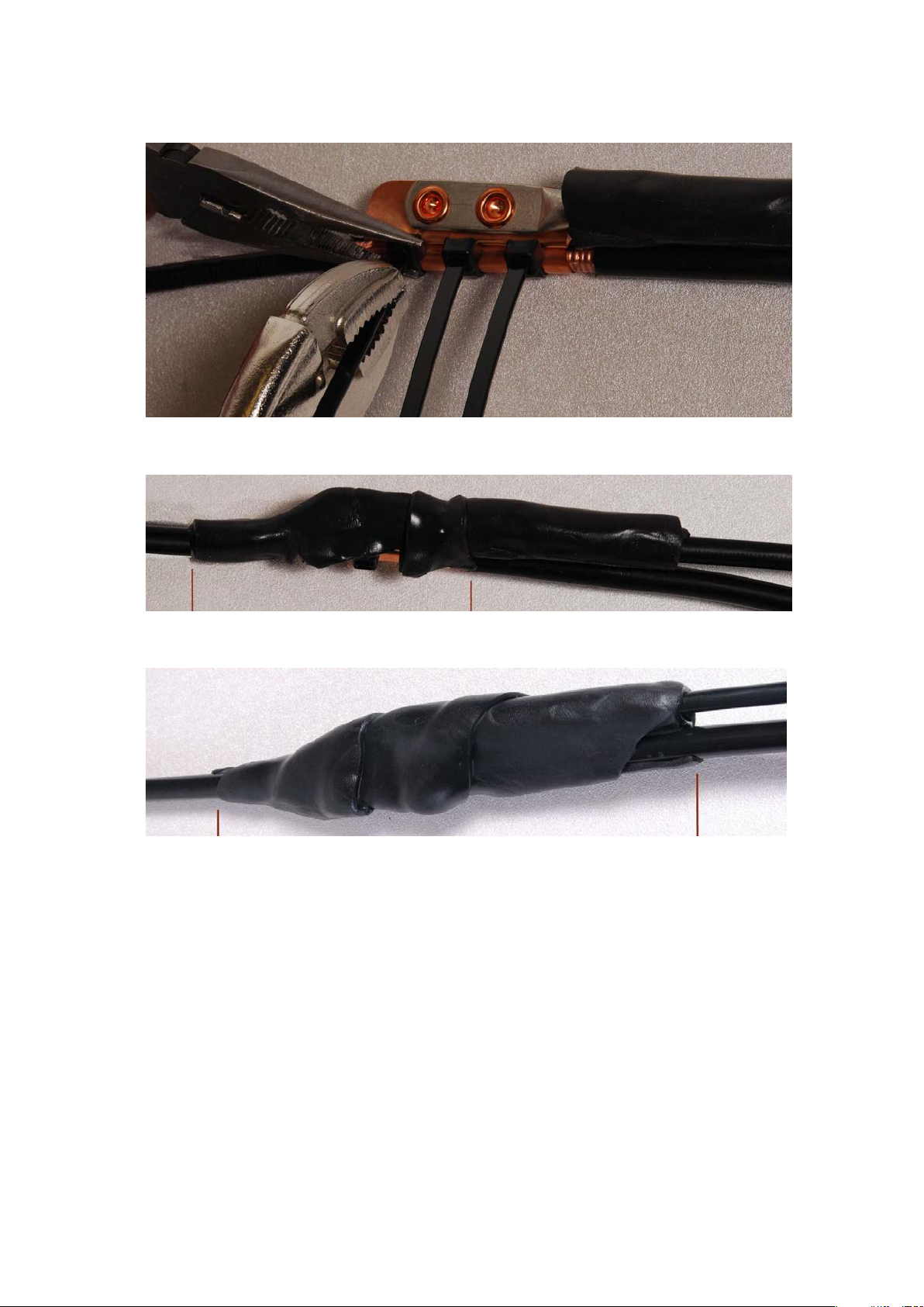
Chapter 5: Installation Supplemental installation information
4
Tighten the cable ties with pliers.
5
Cut a 38mm (1.5 inches) section of self
joint between
6
Use the remainder of the self
tape edges together so that there are no gaps.
Cut the surplus from the cable ties.
-amalgamating tape and wrap it completely around the
the drop and ground cables.
-amalgamating tape to wrap the complete assembly. Press the
Page 5-58
Page 59
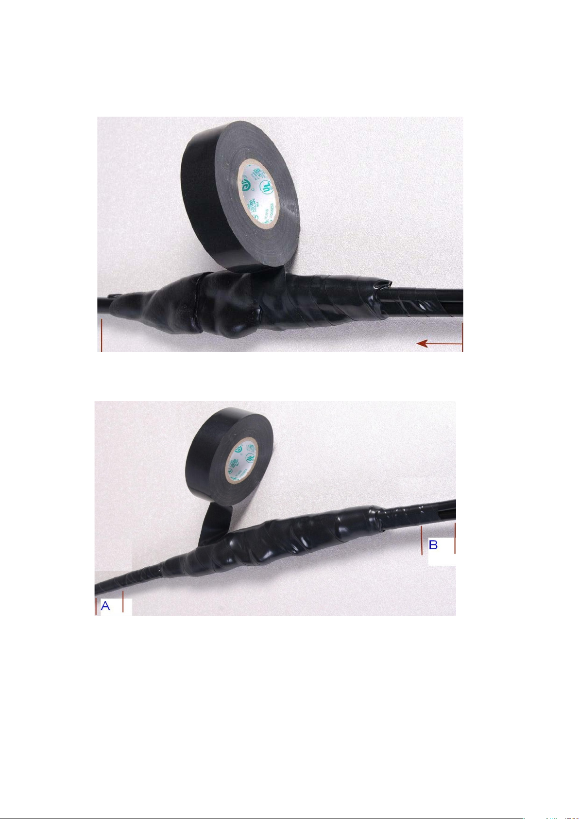
Chapter 5: Installation Supplemental installation information
7
Wrap a layer of
finishing 25
width.
8
Repeat with a further
layers in alternate directions (top to bottom, then bottom
should be 25mm (1 inch) above (A) and 25
9
Prepare the metal grounding point of the supporting structure to provide a good electrical
contact with the grounding cable
oxidant compound liberally between the two metals.
10
Clamp the bottom lug of the grounding cable to the supporting structure using site approved
methods.
protection than a single
PVC tape from bottom to top, starting from 25 mm (1 inch) below and
mm (1 inch) above the edge of the self-amalgamating tape, over lapping at half
four layers of PVC tape, always overlapping at half width. Wrap the
clamp. Remove paint, grease or dirt, if present. Apply anti-
to top). The edges of each layer
mm (1 inch) below (B) the previous layer.
Use a two-hole lug secured with fasteners in both holes. This provides better
-hole lug.
Page 5-59
Page 60
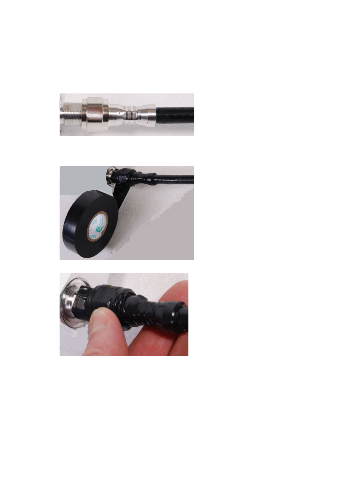
Chapter 5: Installation Supplemental installation information
1
2
3
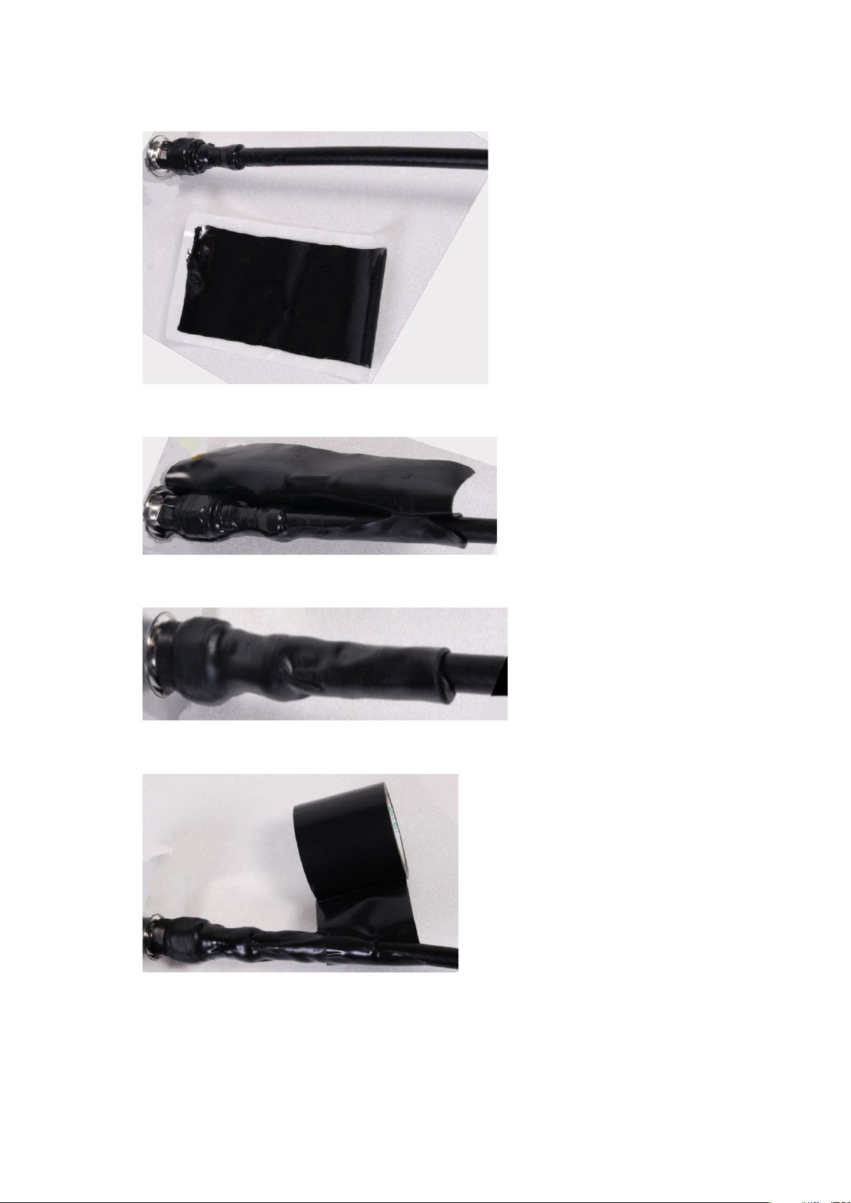
Weatherproofing an N type connector
Use this procedure to weatherproof the N type connectors fitted to the connectorized ODU and
external antenna (if recommended by the antenna manufacturer).
Ensure the connection is tight. A torque wrench should be used if available:
Wrap the connection with a layer of 19 mm (0.75 inch) PVC tape, starting 25 mm (1 inch)
below the connector body. Overlap the tape to half-width and extend the wrapping to the
body of the LPU. Avoid making creases or wrinkles:
Smooth the tape edges:
Page 5-60
Page 61
Chapter 5: Installation Supplemental installation information
4
5
6
7
Cut a 125mm (5 inches) length of rubber tape (self-amalgamating):
Expand the width of the tape by stretching it so that it will wrap completely around the
connector and cable:
Press the tape edges together so that there are no gaps. The tape should extend 25 mm
(1 inch) beyond the PVC tape:
Wrap a layer of 50 mm (2 inch) PVC tape from bottom to top, starting from 25 mm (1 inch)
below the edge of the self-amalgamating tape, overlapping at half width.
Page 5-61
Page 62
Chapter 5: Installation Supplemental installation information
8
9
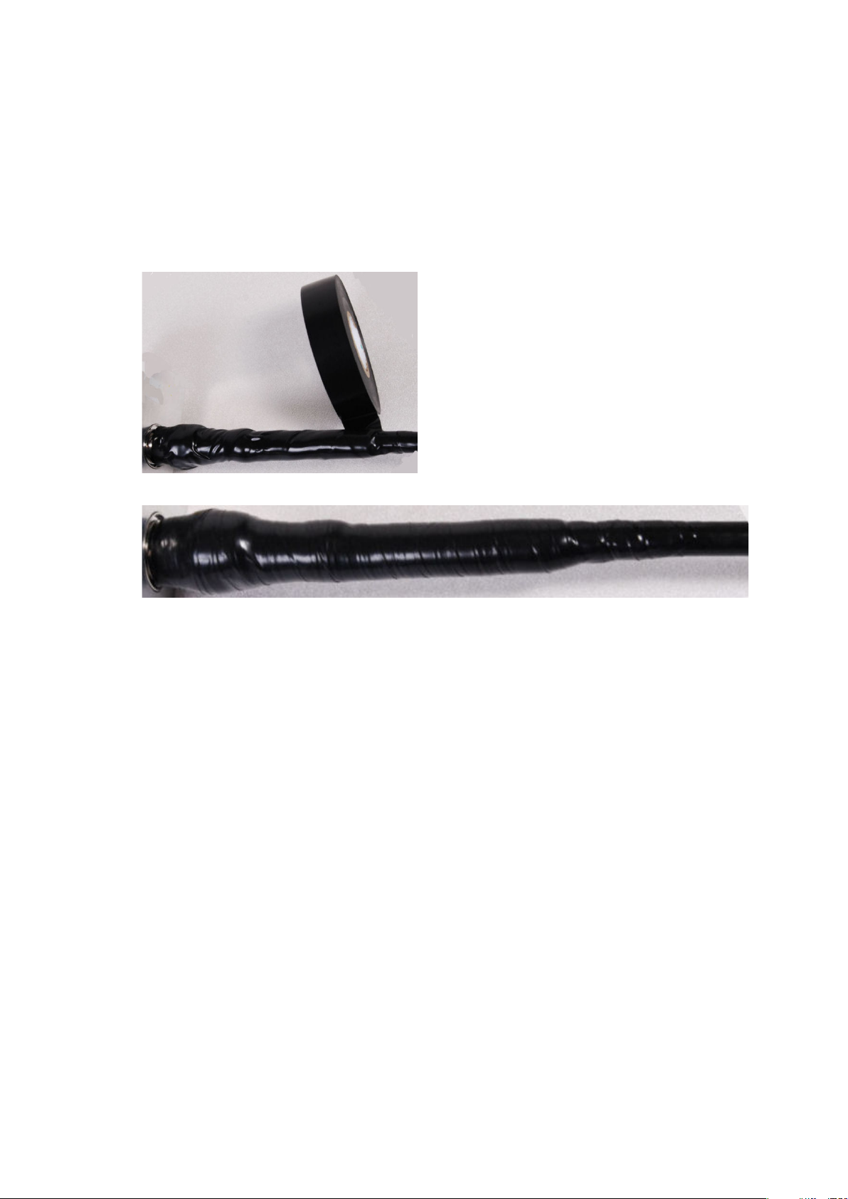
Repeat with a further four layers of 19 mm (0.75 inch) PVC tape, always overlapping at half
width. Wrap the layers in alternate directions:
• Second layer: top to bottom.
• Third layer: bottom to top.
• Fourth layer: top to bottom.
• Fifth layer: bottom to top.
The bottom edge of each layer should be 25 mm (1 inch) below the previous layer.
Check the completed weatherproof connection:
Page 5-62
Page 63
Chapter 5: Installation Supplemental installation information
Note
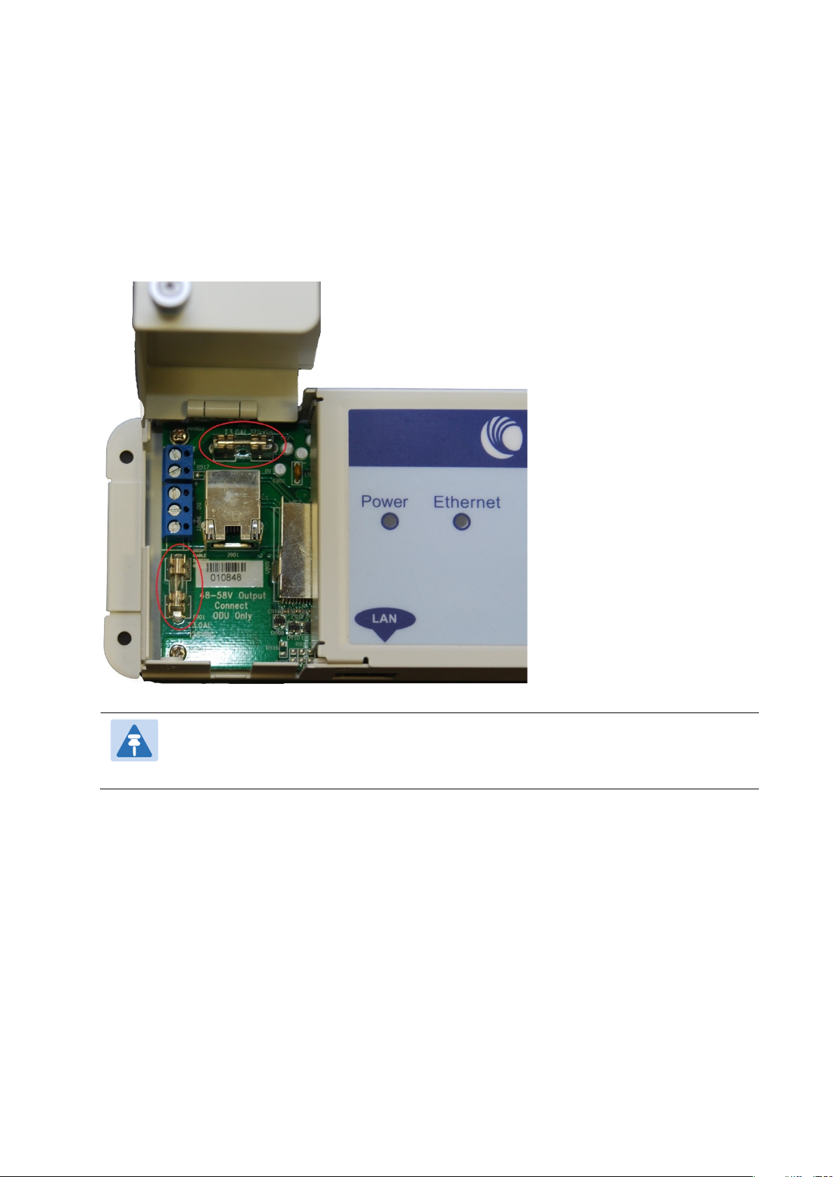
Replacing PSU fuses
The AC+ DC Enhanced Power Injector contains two replaceable fuses. These fuses protect the
positive and negative grounded DC input voltages. If an incorrect power supply (that is, not in
the range 37V to 60V DC) is connected to the DC input terminals, one or both fuses may blow.
Both fuses are 3 Amp slow-blow, for example Littlefuse part number 0229003.
To replace these fuses, undo the retaining screw and hinge back the cover as indicated:
No other fuses are replaceable in the AC+DC Enhanced Power Injector.
Page 5-63
 Loading...