

Cambium Networks 25600 Users manual

PTP 600 Series
User Guide
MOTOROLA POINT-TO-POINT WIRELESS SOLUTIONS


MOTOROLA, Inc.
Point-to-Point Wireless Bridges – PTP 600 Series
Software Release PTP 600-05-00
System User Manual
July 26th, 2007
Ref: PHN-0896-01.08
Copyright Information
This document is the confidential property of Motorola, Inc. and without its prior written consent may
not be copied or released to third parties.
MOTOROLA, the stylized M Logo and all other trademarks indicated as such herein are trademarks
®
of Motorola, Inc.
product or service names are the property of their respective owners.
© 2007 Motorola, Inc. All rights reserved.
http://www.motorola.com/ptp
Reg. U.S. Pat & Tm. Office. PTP 600 is a trademark of Motorola, Inc. All other
Compliance
General
Changes or modifications not expressly approved by Motorola could void the user’s authority to
operate the system.
: This system has achieved Type Approval in various countries around the world. This means
NOTE
that the system has been tested against various local technical regulations and found to comply. The
frequency bands in which the system operates is may be ‘unlicensed’ and, in these bands, the system
can be used provided it does not cause interference. Further, it is not guaranteed protection against
interference from other products and installations.
1

The system has basically been shown to comply with the limits for emitted spurious radiation for a
1
Class B digital device
, pursuant to Part 15 of the FCC Rules in the USA as well as comparable
regulations in other countries. These limits have been designed to provide reasonable
protection
against harmful interference in a residential installation. This equipment generates uses and can
radiate radio frequency energy and, if not installed and used in accordance with the instructions, may
cause harmful interference to radio communications. However, there is no guarantee that interference
will not occur in a particular installation.
If this equipment does cause harmful interference to radio or television reception, which can be
determined by turning the equipment off and on, the user is encouraged to try to correct the
interference by one or more of the following measures:
• Reorient or relocate the Outdoor Unit (ODU).
• Increase the separation between the equipment and ODU.
• Connect the equipment into a power outlet on a circuit different from that to which the
receiver is connected.
• Consult your installer or supplier for help.
Deployment and Operation
The Radio Regulations of various countries’ limits constrain the operation of radio products generally.
In particular the local regulator may limit the amount of conducted or radiated transmitter power and
may require registration of the radio link.
The power transmitted by the PTP 600 Series Bridge is controlled by the use of Region-specific
License Keys.
The following examples show how the regulatory limits apply in some specific countries at the current
time. Operators should note that regulations are subject to change.
Contact your supplier/installer to ensure that your product is set for the correct License Key for your
Country/Region and to ensure that you have fulfilled all the local regulatory requirements, especially if
you are intending to use a link with external antennas. Footnotes to the table below indicate countries
where registration of the link is currently mandatory.
1
Class B Digital Device, A digital device that is marketed for use in a residential environment notwithstanding use in
commercial, business and industrial environments.
2

Regulations applicable to 2.5GHz PTP 600 Series Bridge variant
FCC
Examples of Regulatory Limits at 2.5GHz
Under FCC Regulations, operation of this product
is only allowed with a License Key for Region 16
which ensures that the product will meet the
requirements of FCC part 27.
Note: Spectrum in this band (2499MHz to
2690MHz) is allocated on a Licensed basis in USA.
General Notice Applicable to Europe
N/A.
3

Regulations applicable to 5.4GHz PTP 600 Series Bridge variant
Non-FCC and Non-ETSI2
FCC
Canada
ETSI
General Notice Applicable to Europe
This equipment complies with the essential requirements for the
EU R&E Directive 1999/5/EC.
Examples of Regulatory Limits at 5.4GHz
Equipment can be operated in any mode, best
results will be obtained using Region 8 settings
(Region 7 if DFS is required)
Under FCC Regulations, operation of this product
is only allowed with a License Key for Region 12
(30dBm or 1W EIRP with Radar Detection)
Under IC Regulations, operation of this product is
only allowed with a License Key for Region 13
(30dBm or 1W EIRP with Radar Detection and
barring of the band 5600-5650MHz)
Under ETSI Regulations, operation of this product
is only allowed with a License Key for Region 12
(30dBm or 1W EIRP with Radar Detection)
And
2
Note: In regions other than EU/USA, specific local regulations may apply. It is the responsibility of the installer/user to check
that the equipment as deployed meets local regulatory requirements.
4

A
Regulations applicable to 5.8GHz PTP 600 Series Bridge variant
Examples of Regulatory Limits
USA/ Canada/ Taiwan/ Brazil
3
UK
Equipment can be operated in any mode, best
results will be obtained using Region 1 settings
Under UK Regulations, operation of this product is
allowed with a License Key for Region 4 (3W EIRP
with Radar Detection)
Under Eire Regulations, operation of this product is
only allowed with a License Key for Region 6 (2W
Eire
4
EIRP)
ustralian laws prohibit use/operation of this
Australia
product except where it is used with a License Key
for Region 3 (4W EIRP)
Under Singapore Regulations, operation of this
Singapore
product is only allowed with a License Key for
Region 5 (100mW EIRP)
Under Hong Kong Regulations, operation of this
Hong Kong
product is only allowed with a License Key for
Region 3 (4W EIRP)
Under Korean Regulations, operation of this
Korea
product is only allowed with a License Key for
Region 11 (100mW TX Power, Band restricted to
5725 to 5825MHz)
3
UK Registration of Links – OfCom
The application form may be found at
http://www.ofcom.org.uk/radiocomms/UTH
4
Eire Registration of Links – Commission for Communication Regulation (ComReg)
The application form may be found at
Hhttp://www.comreg.ie/5_8GHzRegPart1.asp?S=4&NavID=198&MT
5

General Notice Applicable to Europe
This equipment complies with the essential requirements for the
EU R&E Directive 1999/5/EC.
The use of 5.8GHz for Point to Point radio links is not harmonized
across the EU and currently the product may only be deployed in
the UK and Eire (IRL); Norway will be available for deployment
from December 2005.
However, the regulatory situation in Europe is changing and the
radio spectrum may become available in other countries in the near
future. Please contact Motorola for the latest situation.
Disclaimer
The parameters quoted in this document must be specifically confirmed in writing
before they become applicable to any particular order or contract. The company
reserves the right to make alterations or amendments to the detail specification at its
GB
!
IRL
0889
discretion. The publication of information in this document does not imply freedom
from patent or other rights of Motorola, Inc. or others.
6

1H1 About This User Guide .......................................................................................................494H23
2H1.1 Interpreting Typeface and Other Conventions ......................................................................495H23
3H1.2 Getting Additional Help ......................................................................................................... 496H25
4H1.3 Sending Feedback ................................................................................................................ 497H25
5H2 Avoiding Hazards................................................................................................................498H26
6H2.1 Preventing Overexposure to RF Energy ...............................................................................499H26
7H2.1.1 Calculations for Separation Distances and Power Compliance Margins.............................. 500H26
8H2.1.1.1 Calculated Distances and Power Compliance Margins ........................................................501H27
9H3 Getting Started ....................................................................................................................502H28
10H3.1 For Your Safety .....................................................................................................................503H28
11H3.2 Welcome ............................................................................................................................... 504H29
12H3.2.1 About This Guide................................................................................................................... 505H29
13H3.2.2 Who Should Use This Guide................................................................................................. 506H29
14H3.2.3 Contact Information ............................................................................................................... 507H30
15H3.2.4 Repair and Service................................................................................................................ 508H30
16H3.3 Product Description............................................................................................................... 509H31
17H3.3.1 The Outdoor Unit (ODU) ....................................................................................................... 510H33
18H3.3.2 PIDU Plus – PTP 600 Series Bridge..................................................................................... 511H34
19H3.3.3 Redundancy and Alternate Powering Configurations ........................................................... 512H36
20H3.3.3.1 External DC Supply Only ......................................................................................................513H36
21H3.3.3.2 External DC Supply and AC Supply...................................................................................... 514H37
22H3.3.3.3 External DC Supply and Redundant AC Supply ................................................................... 515H37
23H3.3.4 Remote LEDs and Recovery Switch..................................................................................... 516H38
24H3.3.5 Cables and connectors ......................................................................................................... 517H38
25H3.3.6 Surge Arrestor ....................................................................................................................... 518H39
26H3.3.7 Mounting Brackets................................................................................................................. 519H39
27H3.3.8 Configuration and Management............................................................................................ 520H40
28H3.4 Warranty................................................................................................................................ 521H40
29H4 Product Architecture .......................................................................................................... 522H41
30H5 General Considerations .....................................................................................................523H43
31H5.1 Spectrum Planning................................................................................................................ 524H43
32H5.2 Introducing the Time Division Duplex (TDD) Synchronization Feature ................................525H45
33H5.2.1 The Problem.......................................................................................................................... 526H45
34H5.2.2 The Solution – Using TDD Synchronization.......................................................................... 527H46
35H5.2.3 Deployment Consideration.................................................................................................... 528H47
7

36H5.2.4 PTP Approach for Using TDD Synchronization ....................................................................529H47
37H5.3 Region Codes........................................................................................................................ 530H48
38H5.4 Operational Restrictions........................................................................................................ 531H49
39H5.4.1 Radar Avoidance................................................................................................................... 532H49
40H5.4.2 RTTT Avoidance and Other Channel Use Restrictions ........................................................533H51
41H5.4.3 Radar Avoidance, i-DFS and Variable (Narrow) Bandwidth Operation ................................ 534H52
42H5.5 2.5GHz Specific Frequency Planning Considerations .......................................................... 535H52
43H5.5.1 Variable Channel Bandwidth Operation................................................................................ 536H52
44H5.5.2 Power Reduction in the Upper Band..................................................................................... 537H54
45H5.6 5.4GHz Specific Frequency Planning Considerations .......................................................... 538H55
46H5.6.1 Raster Considerations........................................................................................................... 539H57
47H5.6.2 Transmit Power Reduction at the Band Edges ..................................................................... 540H57
48H5.7 5.8GHz Specific Frequency Planning Considerations .......................................................... 541H57
49H5.7.1 Raster Considerations........................................................................................................... 542H59
50H5.7.2 Transmit Power Reduction at the Band Edges ..................................................................... 543H59
51H5.8 Distance ................................................................................................................................ 544H60
52H5.9 Networking Information .........................................................................................................545H61
53H5.10 Lightning Protection............................................................................................................... 546H61
54H5.11 Electrical Requirements ........................................................................................................547H61
55H6 Site Planning........................................................................................................................548H62
56H6.1 Site Selection Criteria............................................................................................................ 549H62
57H6.1.1 ODU Site Selection ............................................................................................................... 550H62
58H6.1.2 PTP 600 Series Bridge PIDU Plus Site Selection................................................................. 551H62
59H6.1.3 Path Loss Considerations .....................................................................................................552H63
60H6.1.4 Definitions.............................................................................................................................. 553H63
61H6.1.5 2.5 GHz Product Variant - Receive Sensitivity, Link Loss, Output Power and Threshold Vs
Modulation Mode ..................................................................................................................................
62H6.1.6 5.4 GHz Product Variant - Receive Sensitivity, Link Loss, Output Power and Threshold Vs
Modulation Mode ..................................................................................................................................
63H6.1.7 5.8 GHz Product Variant - Receive Sensitivity, Link Loss, Output Power and Threshold Vs
Modulation Mode ..................................................................................................................................
64H7 Installation ...........................................................................................................................557H67
65H7.1 Preparation............................................................................................................................ 558H67
66H7.2 Installation Procedure ........................................................................................................... 559H67
554H64
555H65
556H66
67H7.3 Tools Required ...................................................................................................................... 560H67
68H7.4 Installation Support................................................................................................................ 561H68
69H7.5 Legal Disclaimer.................................................................................................................... 562H68
8

70H7.6 Mounting the ODUs............................................................................................................... 563H68
71H7.7 Connecting Up....................................................................................................................... 564H70
72H7.7.1 Preparing The PIDU Plus To ODU Cable .............................................................................565H70
73H7.7.2 Making the Connections at the ODU..................................................................................... 566H72
74H7.7.3 Making the PTP 600 Series Bridge PIDU Plus Connection At The ODU ............................. 567H73
75H7.7.4 Routing the Cable.................................................................................................................. 568H74
76H7.7.5 Fitting A Surge Arrestor......................................................................................................... 569H74
77H7.7.6 Grounding the Installation ..................................................................................................... 570H75
78H7.7.7 Making the ODU Connection at the PTP 600 Series Bridge PIDU Plus............................... 571H75
79H7.7.8 Making the Network Connection at The PIDU Plus – PTP 600 Series Bridge ..................... 572H76
80H7.7.9 Mounting the PTP 600 Series Bridge PIDU Plus .................................................................. 573H77
81H7.7.10 Powering Up.......................................................................................................................... 574H79
82H7.7.11 Aligning the PTP 600 Series Bridge ODUs........................................................................... 575H80
83H8 Web Page Reference...........................................................................................................576H82
84H8.1 Home Page – PTP 600 Series Bridge................................................................................... 577H84
85H8.1.1 Home Page Alarm Display .................................................................................................... 578H85
86H8.2 Systems Status Page ............................................................................................................ 579H88
87H8.3 System Administration Pages ............................................................................................... 580H93
88H8.3.1 System Configuration............................................................................................................ 581H94
89H8.3.1.1 General Configuration Page.................................................................................................. 582H95
90H8.3.1.2 LAN Configuration Page .......................................................................................................583H97
91H8.3.1.3 LAN Configuration Page – Use VLAN For Management Interfaces ................................... 584H100
92H8.3.1.4 LAN Configuration Page – Manual Ethernet Configuration ................................................ 585H101
93H8.3.1.5 Save and Restore Configuration File ..................................................................................586H102
94H8.3.1.6 Telecoms Configuration Page............................................................................................. 587H106
95H8.3.2 Statistics Page..................................................................................................................... 588H108
96H8.3.3 Detailed Counters Page ......................................................................................................589H111
97H8.3.4 Install Pages........................................................................................................................ 590H113
98H8.3.4.1 Manually Configuring The Wireless Units ...........................................................................591H115
99H8.3.4.2 Internet Protocol Configuration ...........................................................................................592H116
100H8.3.4.3 Telecoms Interface.............................................................................................................. 593H118
101H8.3.4.4 Wireless Configuration ........................................................................................................594H119
102H8.3.4.5 Disarm ................................................................................................................................. 595H126
103H8.3.5 Graphical Install................................................................................................................... 596H128
104H8.3.6 Software Upgrade ...............................................................................................................597H130
105H8.3.7 Spectrum Management....................................................................................................... 598H134
9

106H8.3.7.1 Wireless Channels ..............................................................................................................599H134
107H8.3.7.2 Spectrum Management Measurements.............................................................................. 600H135
108H8.3.7.3 Measurement Analysis........................................................................................................ 601H135
109H8.3.7.4 The Spectrum Management Master / Slave Relationship................................................... 602H136
110H8.3.7.5 Spectrum Management Configuration ................................................................................603H138
111H8.3.7.6 Barring Channels................................................................................................................. 604H139
112H8.3.7.7 Local and Peer Channel Spectrum Graphics...................................................................... 605H139
113H8.3.7.8 Active Channel History ........................................................................................................ 606H141
114H8.3.7.9 Viewing Historic Spectrum Management Metrics ............................................................... 607H141
115H8.3.8 Spectrum Management (Fixed Frequency and WIMAX) ....................................................608H143
116H8.3.9 Spectrum Management Control - With Operational Restrictions ........................................ 609H144
117H8.3.10 Spectrum Management – Example of 2.5 GHz Product variant ......................................... 610H147
118H8.3.11 Remote Management Page ................................................................................................ 611H148
119H8.3.11.1 SNMP (Simple Network Management Protocol)................................................................. 612H149
120H8.3.11.2 Supported Management Information Bases (MIBS) ...........................................................613H149
121H8.3.11.3 Diagnostics Alarms.............................................................................................................. 614H150
122H8.3.11.4 SNMP Configuration............................................................................................................ 615H151
123H8.3.11.5 SMTP (Simple Mail Transport Protocol).............................................................................. 616H151
124H8.3.11.6 SNTP (Simple Network Time Protocol)............................................................................... 617H152
125H8.3.11.7 Setting the clock .................................................................................................................. 618H152
126H8.3.12 Diagnostics.......................................................................................................................... 619H153
127H8.3.12.1 Diagnostic Plotter ................................................................................................................620H154
128H8.3.12.2 Diagnostics Download......................................................................................................... 621H155
129H8.3.13 Change System Administration Password.......................................................................... 622H156
130H8.3.14 License Key......................................................................................................................... 623H156
131H8.3.15 Properties ............................................................................................................................ 624H158
132H8.3.16 Reboot................................................................................................................................. 625H159
133H9 Recovery Mode..................................................................................................................626H160
134H9.1 Upgrade Software Image .................................................................................................... 627H162
135H9.2 Reset IP & Ethernet Configuration ...................................................................................... 628H164
136H9.3 Erase Configuration............................................................................................................. 629H165
137H9.4 Reboot................................................................................................................................. 630H168
138H10 Fault Finding......................................................................................................................631H169
139H10.1 Hardware............................................................................................................................. 632H169
140H10.1.1 Power .................................................................................................................................. 633H169
141H10.1.2 Ethernet............................................................................................................................... 634H170
10

142H10.1.3 Checking your wiring ........................................................................................................... 635H171
143H10.2 Radio ................................................................................................................................... 636H172
144H10.2.1 No Activity ...........................................................................................................................637H172
145H10.2.2 Some Activity....................................................................................................................... 638H173
146H11 Lightning Protection.........................................................................................................639H174
147H11.1 Overview ............................................................................................................................. 640H174
148H11.1.1 Lightning Protection Zones ................................................................................................. 641H174
149H11.2 Detailed Installation............................................................................................................. 642H175
150H11.3 Testing Your Installation...................................................................................................... 643H182
151H11.3.1 Pre-Power Testing............................................................................................................... 644H182
152H11.3.2 Post-Power Testing ............................................................................................................. 645H182
153H12 Wind Loading.....................................................................................................................646H184
154H12.1 General................................................................................................................................ 647H184
155H12.2 Calculation of Lateral Force ................................................................................................648H184
156H12.3 Capabilities of the PTP 600 Series Bridges ........................................................................649H185
157H12.4 Wind Speed Statistics .........................................................................................................650H185
158H13 PTP 600 Series Bridge – Connectorized Model .............................................................651H187
159H13.1 Scope .................................................................................................................................. 652H187
160H13.2 Product Description............................................................................................................. 653H187
161H13.2.1 Hardware............................................................................................................................. 654H187
162H13.2.2 Antenna Choices – 5.8 GHz................................................................................................ 655H188
163H13.3 Software/Features ............................................................................................................... 656H189
164H13.3.1 Status Page......................................................................................................................... 657H189
165H13.3.2 Configuration Pages............................................................................................................ 658H190
166H13.3.3 Installation Pages ................................................................................................................ 659H191
167H13.4 Deployment Considerations ................................................................................................660H194
168H13.5 Link Budget .........................................................................................................................661H194
169H13.6 Regulatory Issues................................................................................................................ 662H194
170H13.6.1 Antenna Choice (FCC Regions Only) .................................................................................663H194
171H13.6.2 Cable Losses (FCC Regions Only) ..................................................................................... 664H195
172H13.7 Antennas for USA / Canada................................................................................................ 665H195
173H13.8 Installation ...........................................................................................................................666H198
174H13.8.1 Antenna Choice................................................................................................................... 667H198
175H13.8.2 Cables and Connectors....................................................................................................... 668H198
176H13.8.3 Tools.................................................................................................................................... 669H198
177H13.8.4 Miscellaneous supplies .......................................................................................................670H199
11

178H13.8.5 Mounting the Connectorized 600 Series Bridge .................................................................671H199
179H13.8.6 Mounting the antennas........................................................................................................ 672H199
180H13.8.7 Alignment Process ..............................................................................................................673H200
181H13.8.8 Aligning Dual Polar Antennas .............................................................................................674H200
182H13.8.9 Aligning Separate Antennas................................................................................................ 675H200
183H13.8.10 Completing the Installation.................................................................................................. 676H201
184H13.8.11 Antenna Cable Fixing.......................................................................................................... 677H201
185H13.8.12 Antenna Connection Weatherproofing................................................................................ 678H201
186H13.9 Additional Lightning Protection............................................................................................ 679H203
187H13.9.1 ODU Mounted Outdoors ..................................................................................................... 680H203
188H13.9.2 ODU Mounted Indoors ........................................................................................................ 681H204
189H14 TDD Synchronization Configuration and Installation Guide ........................................682H205
190H14.1 Introduction.......................................................................................................................... 683H205
191H14.2 TDD Synchronization Installation and Wiring Guidelines.................................................... 684H206
192H14.2.1 Installing the Recommended GPS Synchronization Kit ...................................................... 685H206
193H14.3 Configuring the TDD Synchronization Feature ................................................................... 686H209
194H14.3.1 TDD Synchronization Enable .............................................................................................. 687H209
195H14.3.2 TDD Synchronization Configuration Menu.......................................................................... 688H210
196H14.3.2.1 TDD Synchronization Configuration – Expert Mode ...........................................................689H214
197H14.3.2.2 Confirm Settings and Reboot ODU ..................................................................................... 690H218
198H15 E1/T1 Installation Guide ...................................................................................................691H220
199H15.1 Preparing the PTP 600 Series Bridge E1/T1 Cable............................................................ 692H220
200H15.2 Making the Connection at the ODU ....................................................................................693H221
201H15.3 Routing the Cable................................................................................................................ 694H224
202H15.4 Fitting a Surge Arrestor ....................................................................................................... 695H224
203H15.5 Customer Cable Termination .............................................................................................. 696H224
204H16 Lightning Protection.........................................................................................................697H227
205H16.1 Overview ............................................................................................................................. 698H227
206H16.2 Recommended Additional Components for E1/T1 Installation. .......................................... 699H227
207H16.3 Surge Arrestor Wiring.......................................................................................................... 700H230
208H16.4 Testing Your Installation...................................................................................................... 701H232
209H16.4.1 Pre-Power Testing............................................................................................................... 702H232
210H17 Data Rate Calculations .....................................................................................................703H234
211H18 AES Encryption Upgrade .................................................................................................704H241
212H18.1 Configuring Link Encryption ................................................................................................705H241
213H18.2 Configuring Link Encryption ................................................................................................706H241
12

214H18.2.1 License Keys ....................................................................................................................... 707H242
215H18.2.2 Encryption Mode and Key ................................................................................................... 708H243
216H18.3 Wireless Link Encryption FAQ ............................................................................................ 709H245
217H18.3.1 Encryption data entry fields are not available .....................................................................710H245
218H18.3.2 Link fails to bridge packets after enabling link encryption................................................... 711H245
219H18.3.3 Loss of AES following downgrade....................................................................................... 712H245
220H19 Legal and Regulatory Notices..........................................................................................713H246
221H19.1 Important Note on Modifications .........................................................................................714H246
222H19.2 National and Regional Regulatory Notices – 5.8 GHz variant ............................................ 715H246
223H19.2.1 U.S. Federal Communication Commission (FCC) and Industry Canada (IC) Notification.. 716H246
224H19.2.2 European Union Notification ............................................................................................... 717H247
225H19.2.3 UK Notification..................................................................................................................... 718H248
226H19.3 National and Regional Regulatory Notices – 5.4 GHz Variant ...........................................719H249
227H19.3.1 U.S. Federal Communication Commission (FCC) and Industry Canada (IC) Notification.. 720H249
228H19.3.2 European Union Notification ............................................................................................... 721H250
229H19.4 National and Regional Regulatory Notices – 2.5 GHz Variant ...........................................722H252
230H19.4.1 U.S. Federal Communication Commission (FCC) Notification ........................................... 723H252
231H19.5 Exposure ............................................................................................................................. 724H253
232H19.6 Legal Notices....................................................................................................................... 725H253
233H19.6.1 Software License Terms and Conditions ............................................................................726H253
234H19.6.2 Hardware Warranty in U.S. ................................................................................................. 727H257
235H19.6.3 Limit of Liability.................................................................................................................... 728H257
236H20 Glossary.............................................................................................................................729H258
237H21 FAQs...................................................................................................................................730H259
238H22 Index...................................................................................................................................731H262
239H23 Specifications....................................................................................................................732H263
240H23.1 System Specifications .........................................................................................................733H263
241H23.1.1 Wireless 2.5 GHz Variant.................................................................................................... 734H263
242H23.1.2 Wireless 5.4GHz Variant..................................................................................................... 735H265
243H23.1.3 Wireless 5.8GHz Variant..................................................................................................... 736H267
244H23.1.4 Management .......................................................................................................................737H269
245H23.1.5 Physical ............................................................................................................................... 738H270
246H23.1.6 Powering .............................................................................................................................739H270
247H23.1.7 Telecoms Interface.............................................................................................................. 740H270
248H23.2 Safety Compliance ..............................................................................................................741H271
249H23.3 EMC Emissions Compliance............................................................................................... 742H271
13

250H23.3.1 2.5GHz Variant.................................................................................................................... 743H271
251H23.3.2 5.4GHz Variant.................................................................................................................... 744H271
252H23.3.3 5.8GHz Variant.................................................................................................................... 745H271
253H23.4 EMC Immunity Compliance................................................................................................. 746H272
254H23.5 Radio Certifications .............................................................................................................747H273
255H23.5.1 2.5 GHz Variant...................................................................................................................748H273
256H23.5.2 5.4GHz Variant.................................................................................................................... 749H273
257H23.5.3 5.8GHz Variant.................................................................................................................... 750H273
258H23.6 Environmental Specifications .............................................................................................. 751H274
259H23.7 System Connections ...........................................................................................................752H274
260H23.7.1 PIDU Plus to ODU and ODU to Network Equipment Connections..................................... 753H274
14

List of Figures
261HFigure 1 - Typical PTP 600 Series Bridge Deployment................................................................... 754H31
262HFigure 2 - Mod Record Label................................................................................................................ 755H32
263HFigure 3 – PTP 600 Series Bridge Outdoor Unit (ODU)....................................................................... 756H33
264HFigure 4 - Power Indoor Unit (PIDU Plus) – PTP 600 Series............................................................... 757H34
265H Figure 5 – PIDU Plus Recovery Switch Location ................................................................................. 758H34
266HFigure 6 – PTP 600 Series Bridge PIDU Plus Power Input.................................................................. 759H35
267HFigure 7 – PTP 600 Series Bridge PIDU Plus to ODU Cable Length Graph .......................................760H36
268HFigure 8 - External DC Supply Only .....................................................................................................761H36
269HFigure 9 - External DC Supply and AC Supply..................................................................................... 762H37
270HFigure 10 - External DC Supply and Redundant AC Supply................................................................ 763H37
271HFigure 11 - Remote LED and Recovery Switch Wiring ........................................................................764H38
272HFigure 12 – PTP 600 Series Bridge Layer Diagram ............................................................................. 765H42
273HFigure 13 - Co-location of Links Interference Problem - A Simple Example ........................................ 766H45
274HFigure 14 - Co-location of Links Interference Problem - TxRx Timing Diagram................................... 767H46
275HFigure 15 - Co-location of Links Interference Problem - Solution to the Simple Example ................... 768H46
276HFigure 16 - 5.8 GHz UK RTTT Channel Avoidance – 30 MHz Channel Bandwidth Only .................... 769H51
277HFigure 17 - 2.5 GHz BRS Band Channel Assignments........................................................................ 770H54
278HFigure 18 - 5.4 GHz Available Spectrum Settings - 30 MHz Channel Bandwidth................................ 771H55
279HFigure 19 - 5.4 GHz Available Spectrum Settings - 15 MHz Channel Bandwidth................................ 772H55
280HFigure 20 - 5.4 GHz Available Spectrum Settings - 10 MHz Channel Bandwidth................................ 773H56
281HFigure 21 - 5.4 GHz Available Spectrum Settings - 5 MHz Channel Bandwidth.................................. 774H56
282HFigure 22 - 5.8 GHz Available Spectrum Settings – 30 MHz Channel Bandwidth............................... 775H57
283HFigure 23 - 5.8 GHz Available Spectrum Settings - 15 MHz Channel Bandwidth................................ 776H58
284HFigure 24 - 5.8 GHz Available Spectrum Settings - 10 MHz Channel Bandwidth................................ 777H58
285HFigure 25 - 5.8 GHz Available Spectrum Settings - 5 MHz Channel Bandwidth.................................. 778H59
286HFigure 26 - 5.8 GHz Band Edge TX Power Reduction (Region Code 1 Only) – 30 MHz Channel
Bandwidth Operation.....................................................................................................................
287HFigure 27 - Mounting to pole diameters 25mm (1”) to 50mm (2”) ........................................................780H69
288HFigure 28 - Integral Safety Loop ........................................................................................................... 781H69
289HFigure 29 - Completed ODU connector................................................................................................ 782H71
290HFigure 30 - RJ45 Pin Connection (T568B Color Coding) .....................................................................783H71
779H60
291HFigure 31 – PTP 600 Series Bridge PIDU Plus Connection................................................................. 784H72
292HFigure 32 - Disconnecting the ODU...................................................................................................... 785H74
293HFigure 33 - Making the Network Connection at the PIDU Plus ............................................................ 786H76
294HFigure 34 – PTP 600 Series PIDU Plus Drip Loop Configuration ........................................................787H78
15

295HFigure 35 - Menu Navigation Bar.......................................................................................................... 788H83
296HFigure 36 - System Summary Page ..................................................................................................... 789H84
297HFigure 37 - Alarm Warning Triangle .....................................................................................................790H85
298HFigure 38 - Status Page........................................................................................................................ 791H88
299HFigure 39 - System Administration Login Page .................................................................................... 792H93
300HFigure 40 - System Configuration Page ............................................................................................... 793H95
301HFigure 41 - LAN Configuration Page .................................................................................................... 794H97
302HFigure 42 - Configuration Reboot Page................................................................................................ 795H99
303HFigure 43 - Configuration Reboot Page - Ethernet Auto Negotiation Disabled.................................... 796H99
304HFigure 44 - VLAN Configuration Fields............................................................................................... 797H100
305HFigure 45 - LAN Configuration Page - Manual Ethernet Configuration.............................................. 798H101
306HFigure 46 - Save and Restore Configuration Page ............................................................................799H102
307HFigure 47 - Save Configuration File Screen ....................................................................................... 800H103
308HFigure 48 – PTP 600 Example Configuration File .............................................................................. 801H103
309HFigure 49 - Restore Configuration File Pop Up Screen...................................................................... 802H104
310HFigure 50 - Reset Configuration and Reboot Confirmation Pop-up ...................................................803H105
311HFigure 51 - Telecoms Data Entry........................................................................................................ 804H106
312HFigure 52 - System Statistics..............................................................................................................805H108
313HFigure 53 - Detailed Counters Page................................................................................................... 806H111
314HFigure 54 - License Key Data Entry.................................................................................................... 807H115
315HFigure 55 - Installation Wizard Internet Protocol Configuration.......................................................... 808H116
316HFigure 56 - VLAN Warning .................................................................................................................809H117
317HFigure 57 - Telecoms Configuration Interface ....................................................................................810H118
318HFigure 58 – 5.8 GHz and 5.4 GHz Variants - Installation Wizard Wireless Configuration ................. 811H119
319HFigure 59 - 2.5 GHz Variant - Installation Wizard Wireless Configuration .........................................812H120
320HFigure 60 – 5.8 GHz and 5.4 GHz Variants - Fixed Frequency Operation......................................... 813H123
321HFigure 61 - 2.5 GHz Variant - Fixed Frequency Operation.................................................................814H123
322HFigure 62 – 5.8 GHz and 5.4 GHz Variants - Installation Wizard Confirm Configuration................... 815H124
323HFigure 63 - 2.5 GHz Variant - Installation Wizard Confirm Configuration........................................... 816H125
324HFigure 64 - Reboot Confirmation Pop Up ...........................................................................................817H125
325HFigure 65 – 5.8 GHz and 5.4 GHz Variant - Disarm Installation ........................................................ 818H126
326HFigure 66 - 2.5 GHz Variant - Disarm Installation............................................................................... 819H127
327HFigure 67 - Optional Post Disarm Configuration 1.............................................................................. 820H128
328HFigure 68 - Optional Post Disarm Configuration 2.............................................................................. 821H128
329HFigure 69 – Graphical Installation Screen .......................................................................................... 822H129
330HFigure 70 - Software Upgrade ............................................................................................................823H130
331HFigure 71 - Software Upgrade Image Check...................................................................................... 824H131
16

332HFigure 72 - Software Download Progress Indicator............................................................................ 825H132
333HFigure 73 - Software Upgrade Complete............................................................................................ 826H132
334HFigure 74 - Reboot Confirmation Pop Up ...........................................................................................827H133
335HFigure 75 - Spectrum Management as seen from the Master............................................................ 828H137
336HFigure 76 - Spectrum Management as seen from the Slave.............................................................. 829H137
337HFigure 77 - Example Spectrum Management Graphic ....................................................................... 830H139
338HFigure 78 - Active Channel History Screen ........................................................................................ 831H141
339HFigure 79 - Spectrum Management Time Series Plot ........................................................................832H141
340HFigure 80 - Spectrum Management Fixed Frequency Screen ...........................................................833H143
341HFigure 81 - Spectrum Management Help Page (Fixed Frequency) ...................................................834H144
342HFigure 82 - Spectrum Management Master Screen With Operational Restrictions ...........................835H145
343HFigure 83 - Spectrum Management Slave Screen With Operational Restrictions .............................836H146
344HFigure 84 - 2.5 GHz Example of Spectrum Management Page......................................................... 837H147
345HFigure 85 - Remote Management....................................................................................................... 838H148
346HFigure 86 - Remote Management - Diagnostic Alarms ......................................................................839H150
347HFigure 87 - Diagnostic Plotter ............................................................................................................. 840H154
348HFigure 88 - CSV Download................................................................................................................. 841H155
349HFigure 89 - Password Change............................................................................................................ 842H156
350HFigure 90 - Software License Key Data Entry .................................................................................... 843H156
351HFigure 91: License Key reboot Screen ...............................................................................................844H157
352HFigure 92 - Reboot Confirmation Pop Up ...........................................................................................845H157
353HFigure 93 – Properties ........................................................................................................................846H158
354HFigure 94 - System Reboot................................................................................................................. 847H159
355HFigure 95 - Reboot Confirmation Pop Up ...........................................................................................848H159
356HFigure 96 - Recovery Mode Warning Page ........................................................................................849H160
357HFigure 97 - Recovery Options Page ...................................................................................................850H161
358HFigure 98 - Software Download Progress Indicator Page ..................................................................851H162
359HFigure 99 - Software Download Complete Page ................................................................................ 852H162
360HFigure 100 - Reboot Confirmation Pop Up ......................................................................................... 853H163
361HFigure 101 - Confirm Reset to Factory Default Pop Up...................................................................... 854H164
362HFigure 102 - IP and Ethernet Erased Successfully page.................................................................... 855H164
363HFigure 103 - Reboot Confirmation Pop Up ......................................................................................... 856H165
364HFigure 104 - Confirm Erase Configuration Pop Up............................................................................. 857H165
365HFigure 105 - Erase Configuration Successful Page ...........................................................................858H166
366HFigure 106 – Erase Configuration - Reboot Confirmation Pop Up ..................................................... 859H167
367HFigure 107 – Recovery - Reboot Confirmation Pop Up...................................................................... 860H168
368HFigure 108 - Main System Connections ............................................................................................. 861H169
17

369HFigure 109 - ODU mounted in Zones A & B ....................................................................................... 862H176
370HFigure 110 - Showing how the use of a Finial enables the ODU to be mounted inside Zone B ........ 863H176
371HFigure 111 - Diagrammatically showing typical wall and mast installations....................................... 864H177
372HFigure 112 - Upper Grounding Configuration ..................................................................................... 865H178
373HFigure 113 - Lower Grounding Configuration .....................................................................................866H179
374HFigure 114 - Surge Arrestor ALPU-ORT Connection Illustration........................................................ 867H181
375HFigure 115 - Simplified Circuit Diagram (Only One Transtector Shown For Clarity).......................... 868H182
376HFigure 116 – Connectorized 600 Series Bridge Outdoor Unit............................................................ 869H187
377HFigure 117 - Connectorized 600 Series bridge Status Page.............................................................. 870H189
378HFigure 118 - Connectorized 600 Series bridge ‘System Configuration’ Page....................................871H190
379HFigure 119 - Connectorized PTP 600 Series Bridge ‘Installation Wizard’ Page ................................872H191
380HFigure 120 - Connectorized 600 Series bridge ‘Confirm Installation’ Page........................................873H192
381HFigure 121 - Connectorized 600 Series bridge ‘Disarm Installation’ Page......................................... 874H193
382HFigure 122 - Forming a Drip Loop ...................................................................................................... 875H201
383HFigure 123 - Weatherproofing the Antenna Connections................................................................... 876H202
384HFigure 124- Additional Grounding When Using Connectorized Units ................................................877H203
385HFigure 125 - Lightning Arrestor Mounting........................................................................................... 878H204
386HFigure 126 - Polyphaser Assembly.....................................................................................................879H204
387HFigure 127 - GPS Synchronization Unit..............................................................................................880H207
388HFigure 128 - GPS Synchronization Unit Connections ........................................................................881H207
389HFigure 129 - TDD Sync - PTP600 Deployment Diagram.................................................................... 882H208
390HFigure 130- GPS Synchronization Unit Complete Installation............................................................ 883H208
391HFigure 131 - Enabling TDD Synchronization Feature......................................................................... 884H209
392HFigure 132 - Configuring TDD Synchronization Feature – Screen 1..................................................885H210
393HFigure 133 - Configuring TDD Synchronization Feature - Screen 2 ..................................................886H213
394HFigure 134 - Configure TDD Synchronization Expert Mode............................................................... 887H214
395HFigure 135 - Confirm TDD Synchronization Configuration Parameters .............................................888H218
396HFigure 136 - Disarm Following TDD Synchronization ........................................................................889H219
397HFigure 137 - Completed ODU Connector ........................................................................................... 890H220
398HFigure 138 - RJ45 Pin Connection (T568B Color Coding) .................................................................891H221
399HFigure 139 - PIDU Plus and E1-T1 Connection .................................................................................892H221
400HFigure 140 - Disconnecting the ODU..................................................................................................893H223
401HFigure 141 - Example of a Balun ........................................................................................................ 894H224
402HFigure 142 - Diagrammatically Showing the E1-T1 Connections....................................................... 895H225
403HFigure 143 - Two E1-T1-120 Ohms signal Balanced to PTP600 Interface........................................ 896H226
404HFigure 144 - Typical Mast Installation with the addition of the E1-T1 cable....................................... 897H228
405HFigure 145 - Wall Installation with the addition of E1-T1 cable ..........................................................898H229
18

406HFigure 146 - Surge Arrestor ALPU-ORT Connection Illustration........................................................ 899H231
407HFigure 147 - Simplified Circuit Diagram (Only One Transtector Shown For Clarity).......................... 900H232
408HFigure 148 - BPSK 0.63 Single Payload.............................................................................................901H234
409HFigure 149 - QPSK 0.63 Single Payload ............................................................................................902H235
410HFigure 150 - QPSK 0.87 Single Payload ............................................................................................903H235
411HFigure 151 - 16 QAM 0.63 Single Payload......................................................................................... 904H236
412HFigure 152 - 16 QAM 0.87 Single Payload......................................................................................... 905H236
413HFigure 153 - 64 QAM 0.75 Single Payload......................................................................................... 906H237
414HFigure 154 - 64 QAM 0.92 Single Payload......................................................................................... 907H237
415HFigure 155 - 256 QAM 0.81 Single Payload....................................................................................... 908H238
416HFigure 156 - 16 QAM 0.63 Dual Payload ...........................................................................................909H238
417HFigure 157 - 16 QAM 0.87 Dual Payload ...........................................................................................910H239
418HFigure 158 - 64 QAM 0.75 Dual Payload ...........................................................................................911H239
419HFigure 159 - 64 QAM 0.92 Dual Payload ...........................................................................................912H240
420HFigure 160 - 256 QAM 0.81 Dual Payload .........................................................................................913H240
421HFigure 161 – AES Software License Key Data Entry .........................................................................914H242
422HFigure 162 – AES Configuration Data Entry Page .............................................................................915H243
423HFigure 163 - Configuration Reboot Screen......................................................................................... 916H244
424HFigure 164 - Cable Connection Diagram (T568B Color Coding)........................................................ 917H274
19

List of Tables
425HTable 1 - Font types............................................................................................................................ 918H23
426HTable 2 - Admonition types................................................................................................................... 919H24
427HTable 3 - Power Compliance Margins ..................................................................................................920H27
428HTable 4 - Contact Information ............................................................................................................... 921H30
429HTable 5 - PTP 600 Series Bridge Frequency Variants .........................................................................922H43
430HTable 6 – PTP 600 Series Bridge Region Code Definitions................................................................. 923H49
431HTable 7 - 2.5 GHz Product Variant Channel Plan................................................................................. 924H53
432HTable 8 - Power Reduction in the Upper Band..................................................................................... 925H54
433HTable 9 - 5.8 GHz Band Edge Tx Power Reduction –.......................................................................... 926H59
434HTable 10 - 2.5GHz – Receive Sensitivity, Link Loss, Output Power and Threshold Vs Modulation
Mode..............................................................................................................................................
435HTable 11 – 5.4GHz – Receive Sensitivity, Link Loss, Output Power and Threshold Vs Modulation
Mode..............................................................................................................................................
436HTable 12 - 5.8GHz – Receive Sensitivity, Link Loss, Output Power and Threshold Vs Modulation
Mode..............................................................................................................................................
437HTable 13 - Audio indications from the ODU.......................................................................................... 930H80
438HTable 14 – 600 Series Bridge Factory Configuration Values .............................................................931H114
439HTable 15 - Spectrum Management change state key......................................................................... 932H140
440HTable 16 - Spectrum Management Time Series Key .........................................................................933H142
441HTable 17 - Spectrum Management Change State Key With Operational Restrictions....................... 934H146
442HTable 18 - Resistance Table Referenced To The RJ45 at the PIDU+ ...............................................935H172
443HTable 19 - Protection Requirements...................................................................................................936H177
444HTable 20 - Surge Arrestor ALPU-ORT Cable 1 Termination ..............................................................937H180
445HTable 21 - Surge Arrestor ALPU-ORT Cable 2 Termination ..............................................................938H180
446HTable 22 - Lateral Force – Imperial ....................................................................................................939H184
447HTable 23 - Lateral Force – Metric .......................................................................................................940H185
448HTable 24 - Cable Losses per Length ..................................................................................................941H195
927H64
928H65
929H66
449HTable 25 - Allowed Antennas for Deployment in USA/Canada ..........................................................942H197
450HTable 26 - Common Burst Durations .................................................................................................. 943H211
451HTable 27 - TDD Frame Duration ......................................................................................................... 944H215
452HTable 28 - PTP 600 Burst Durations................................................................................................... 945H216
453HTable 29 - Burst Durations in TDM Link Optimization ........................................................................946H217
454HTable 30 - Protection Requirements...................................................................................................947H227
455HTable 31 - Surge Arrestor ALPU-ORT Cable 1 Termination ..............................................................948H230
456HTable 32 - Surge Arrestor ALPU-ORT Cable 2 Termination ..............................................................949H230
20

457HTable 33 - Resistance Table Referenced To the E1/T1 Source ........................................................ 950H233
458HTable 34 - US FCC IDs and Industry Canada certification numbers.................................................. 951H247
459HTable 35 - US FCC IDs and Industry Canada certification numbers.................................................. 952H249
460HTable 36 - US FCC IDs and Industry Canada certification numbers.................................................. 953H252
461HTable 37 - Telecoms Connection Pin Out........................................................................................... 954H275
21

List of Equations
462HEquation 1 - Path Loss ......................................................................................................................... 955H63
463HEquation 2 - Link Loss ..........................................................................................................................956H91
22

1 About This User Guide
This guide covers the installation, commissioning, operation and fault finding of the Motorola
PTP 600 Series of Point-to-Point Wireless Ethernet Bridges.
1.1 Interpreting Typeface and Other Conventions
This document employs distinctive fonts to indicate the type of information, as described in
Table 1.
Font Type of Information
variable width bold
constant width regular
constant width italic
constant width bold
constant width bold
italic
This document employs specific imperative terminology as follows:
• Type means press the following characters.
• Enter means type the following characters and then press Enter.
• Highlight means click anywhere in a row of data to highlight the entire row.
• Select means use the mouse to click on or branch to the menu item that follows.
Use this table and the Glossary to aid in interpreting the technical acronyms used throughout
this User Guide.
Selectable option in a graphical user interface or
settable parameter in a web-based interface.
Literal system response in a command-line interface.
Variable system response in a command-line interface.
Literal user input in a command-line interface.
Variable user input in a command-line interface.
Table 1 - Font types
23
This document also employs a set of consistently used admonitions. Each type of admonition
has a general purpose that underlies the specific information in the box. These purposes are
indicated in
Admonition
Label
957HTable 2.
General Message
Note Informative content that may:
• Defy common or cursory logic.
• Describe a peculiarity of the 600 Series solutions implementation.
• Add a conditional caveat.
• Provide a reference.
• Explain the reason for a preceding statement or provide background
for what immediately follows.
Recommendation Suggestion for an easier, quicker, or safer action or
practice.
Important Informative content that may:
• Identify an indication that you should watch for.
• Advise that your action can disturb something that you may not want
disturbed.
• Reiterate something that you presumably know but should always
keep in mind.
Caution! A notice that the risk of harm to equipment or service exists.
Warning! A notice that the risk of harm to person exists.
Table 2 - Admonition types
24

1.2 Getting Additional Help
To get information or assistance as soon as possible for problems that you encounter, use
the following sequence of action:
1. Search this document, the user manuals that support the modules, and the software
release notes of supported releases:
a. In the Table of Contents for the topic.
b. In the Adobe Reader® search capability for keywords that apply.
5
4F
2. Visit the Motorola website at
3. Ask your Motorola products supplier to help.
4. Gather information from affected units such as:
a. the IP addresses and MAC addresses
b. the software releases
c. the configuration of software features
d. any available diagnostic downloads
5. Escalate the problem to Motorola Technical Support as follows. You may either:
a. Send e-mail to
b. Call our 24/7 Technical Center on +1 (0) 877 515 0400 (Worldwide) and +44 (0)
808 234 4640 (UK).
For warranty assistance, contact your reseller or distributor for the process.
1.3 Sending Feedback
464Hwww.motorola.com/ptp
465Hsupport.ptp@motorola.com
We welcome your feedback on the PTP 600 Series Bridge system documentation. This
includes feedback on the structure, content, accuracy, or completeness of our documents,
and any other comments you have.
5
Reader is a registered trademark of Adobe Systems, Incorporated.
25

2 Avoiding Hazards
2.1 Preventing Overexposure to RF Energy
Caution To protect from overexposure to RF energy, install the radios for the 600 family of
PTP wireless solutions so as to provide and maintain the minimum separation distances from
all persons as shown in
958HTable 3.
When the system is operational, avoid standing directly in front of the antenna. Strong RF
fields are present when the transmitter is on. The Outdoor Unit (ODU) must not be deployed
in a location where it is possible for people to stand or walk inadvertently in front of the
antenna.
At these and greater separation distances, the power density from the RF field is below
generally accepted limits for the general population.
Note These are conservative distances that include compliance margins.
2.1.1 Calculations for Separation Distances and Power Compliance Margins
Limits and guidelines for RF exposure come from:
• US FCC limits for the general population. See the FCC web site at
and the policies, guidelines, and requirements in Part 1 of Title 47 of the Code of Federal
Regulations, as well as the guidelines and suggestions for evaluating compliance in FCC
OET Bulletin 65.
• Health Canada limits for the general population. See the Health Canada web site at
466Hhttp://www.fcc.gov,
467Hhttp://www.hc-sc.gc.ca/rpb and Safety Code 6.
• ICNIRP (International Commission on Non-Ionizing Radiation Protection) guidelines for
the general public. See the ICNIRP web site at
468Hhttp://www.icnirp.de/ and Guidelines for
Limiting Exposure to Time-Varying Electric, Magnetic, and Electromagnetic Fields.
The applicable power density exposure limits from the documents referenced above are:
• 6 W/m
• 10 W/m
2
for RF energy in the 900-MHz frequency band in the US and Canada.
2
for RF energy in the 2.4-, 5.2-, 5.4-, and 5.8-GHz frequency bands.
26
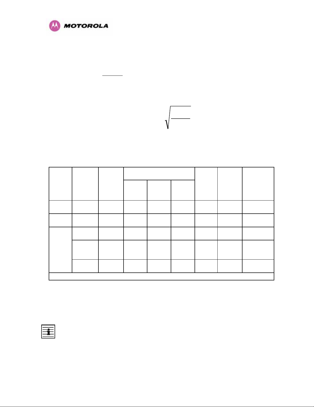
Peak power density in the far field of a radio frequency point source is calculated as follows:
=
Rearranging terms to solve for distance yields
2.1.1.1 Calculated Distances and Power Compliance Margins
959HTable 3 shows calculated minimum separation distances d, recommended distances and
resulting power compliance margins for each frequency band and antenna combination.
2.5 GHz Integrated 0.25 0.125
5.4 GHz Integrated
S
Integrated
GP
π
0.005
0.32
2
4.d
Average
Transmit
Power in
Burst
(Watt)
(7dBm) 0.0025
(25dBm)
Where S = power density in W/m2
P = Maximum Average transmit power capability of the radio, in W
G = total Tx gain as a factor, converted from dB
d = distance from point source, in m
GP
.
d
=
S
.4
π
Variable Band Antenna Max
P (Watt) G S
63
(18dBi) 10 0.25 2 8
200
(23dBi) 10 006 1 16
200
0.16
(23dBi)
2
(W/m
10 0.5 2 4
1
(m) Recom-
D
)
mended
Distance
(m)
Power
Compliance
Margin
5.8 GHz
1. Calculated
External
2ft Flat
Plate
External
6ft Dish
Notes:
1. The regulations require that the power used for the calculations is the maximum power in
the transmit burst subject to allowance for source-based time-averaging.
2. At 5.4GHz the product is generally to a fixed EIRP which can be achieved with the
Integrated Antenna. If there are no EIRP limits, use the distance calculations for 5.8GHz.
3. At 5.8GHz, for antennas between 2ft and 6ft, alter the distance proportionally to the
antenna gain.
4. At 2.5GHz, with a 4/12ft dish, the safe distance is increased to 08/2.4m.
0.32
(25dBm)
0.32
(25dBm)
631
0.16
0.16
Table 3 - Power Compliance Margins
(28dBi)
6310
(38dbi)
27
10 0.9 4 4.5
10 2.83 10 3.5

3 Getting Started
3.1 For Your Safety
WARNING: Use extreme care when installing antennas near power lines.
WARNING: Use extreme care when working at heights.
WARNING: The Outdoor Unit (ODU) for the PTP 600 Series Bridge must be properly
grounded to protect against lightning. It is the user’s responsibility to install the equipment in
accordance with Section 810 of the National Electric Code, ANSI/NFPA No.70-1984 or
Section 54 of the Canadian Electrical Code. These codes describe correct installation
procedures for grounding the outdoor unit, mast, lead-in wire and discharge unit, size of
grounding conductors and connection requirements for grounding electrodes. It is
recommended that installation of the outdoor unit be contracted to a professional installer.
WARNING: The ODU for the PTP 600 Series Bridge must be grounded to a Protective Earth
as described in Section
960H5.7.6 ”961H Grounding The Installation” of this Installation Manual and in
accordance with the Local Electrical Regulations.
WARNING: It is recommended that the supplied Power Indoor Plus (PIDU Plus) – PTP 600
Series is used to power the PTP 600 Series Bridge ODU. The use of other power sources
may invalidate safety approval and affect your warranty.
WARNING: When using alternate DC supplies (via the PIDU Plus DC in terminals as
described in Section
962H1.3.3 “963HRedundancy and Alternate Powering Configurations”), such as
battery-backed DC power source, the supply MUST comply with the following requirements:
• The voltage and polarity is correct and is applied to the correct terminals in the PIDU Plus
• The power source is rated as SELV
• The power source is rated to supply at least 1A continuously, and
• The power source cannot provide more than the Energy Hazard Limit as defined by
IEC/EN/UL6090, Clause 2.5, Limited Power (The Energy Hazard Limit is 240VA)
CAUTION: Users and installers should note that the main power supply is the primary
disconnect device.
28
 Loading...