

Page 1

823G GigaHub Quick Start/Safety and Regulatory
Statements Guide
This document provides general installation practices for the GigaHub model 823G.
This document also provides guidance for site preparation, installation, and basic
troubleshooting.
Scan the QR code at left to access the installation instructions
for this product. All product documentation is available online
from the Calix Resource Center (support.calix.com).
Package Contents
GigaHub - Model 823G
Power adapter (Optional - may ship separately or with UPS*)
Tabletop mounting stand
GigaHub Quick Start Guide (this document)
Product identifi cation labels with login credentials (x2)
* Note: For instructions on installing the optional UPS, refer to the GigaHub Installa-
tion Guide.
P/N 220-01067, Rev 10
www.calix.com
Page 2

A Quick Look
POWER
SERVICE
PHONE1
PHONE2
WPS
RF
Power
Broadband
Service
2.4 GHz Wi-Fi
Ethernet 1-4
Phone 1-2
RF Video
Wi-Fi
Protected
Setup
RESET RF ON/OFF POWER
PHONE
Phone 1-2
ETHERNET
Ethernet 1-4
Reset (Factory
Default)
RF Video
Power On/Off
(Model 823G-2 only)
Incoming Power
7620
ETHERNET 2
ETHERNET 1
PHONE 1
PHONE 2
USB
BROADBAND
WIFI2.4GHz
ETHERNET1
ETHERNET2
ETHERNET3
ETHERNET4
Installation Variables
Before installing the 823G GigaHub, consider what additional services may be implemented. Various Ethernet and telephone ports are available on the back of the unit which may or may not be
used. Prior to determining the unit’s fi nal location, you need to account for the following variables:
• Where will the telephone lines be routed?
• Where will the Ethernet cables be routed?
• What type of building material is used in the home? Make sure you have the appropriate
drills, drill bits and fasteners for routing subscriber services and/or power cables as they pass
through walls and the like.
Tabletop Mounting
The 823G GigaHub can be mounted on a tabletop in a “tower” confi guration using the tabletop
stand shipped with the product.
Assemble the tabletop stand and the GigaHub as shown in the following diagram.
Line-up GigaHub and
1
Tabletop Stand as shown.
Allow a 9/16” offset between
the bottom corner of the GigaHub
and the top edge of the Tabletop Stand
Push stand to the right while
pulling the GigaHub to the
3
left until locked into place
— 2 —
Slide GigaHub down
2
onto Tabletop Stand until
flush
Page 3

Connecting the Equipment
In order to facilitate table-top mounting of the 823G GigaHub, do the following.
1. Remove the 823G GigaHub from its packaging and inventory all parts.
2. Remove the fi ber access cover and set aside temporarily.
3. Plug in the power adapter to an available wall socket and attach the other end to the Gigahub’s power port.
4. Attach the fi ber pigtail to the bulkhead fi tting on the GigaHub until it snaps into place. Re-in-
stall the fi ber access cover.
5. Push the ON/OFF switch (model 823G-2 only) to ON and allow the GigaHub to boot up
(about 3 minutes)
.
Note: To ensure proper airfl ow around the unit, do not block the sides of the GigaHub.
PHONE
ETHERNET
4 3 2 1
1 2
Reset
RF
ON/OFF
7640
Ethernet Cable
POWER
Power Adapter (110/220 VAC)
WAN Interface
(Fiber)
Connecting Outside Services
Subscriber voice, IP video and data services are attached to the rear of the GigaHub.
1. Locate the telephone, video, and data cables coming from the subscriber’s home.
2. Connect the incoming telephone lines to the RJ-11 connectors on the rear of the GigaHub.
3. Connect CAT5 or better Ethernet cables to the LAN Ethernet Ports (RJ-45) for direct at-
tached devices.
4. Secure all sub
scriber service wiring as appropriate.
Default Device Settings
Inserted inside the shipping carton of each 823G GigaHub, the inventory label (x2) provides necessary product information that may be attached to a work order or applied to the exterior of the
device for future reference.
— 3 —
Page 4
• Serial Number of the 823G GigaHub
• ONU MAC address
• Default Wi-Fi security type
• Wi-Fi security key (WPA Key)
• Default IP address of the home gateway router (needed at initial turn-up)
• Default login credentials (User Name/Password)
Getting Started
To turn up network services on the 823G GigaHub, two options are available:
1. Connect an active optical fi ber to the 823G GigaHub’s bulkhead fi tting, power the unit on, and
allow the network OLT (for example, a Calix E7) to discover the device as an unprovisioned
ONT. At the OLT, the network administrator will provision the GigaHub and provide operational
parameters remotely.
2. With the fi ber disconnected, access the Smart Activate or Voice Activate application included
with the 823G and then enter the Registration ID into the application. With the Registration ID
having previously been entered at the OLT, once the fi ber is connected, the GigaHub will come
up as a provisioned ONT based on the pre-provisioning that was completed for that Registration
ID.
Home Gateway Settings
To turn up home gateway services on the 823G GigaHub, complete the following tasks:
1. Connect your PC to any LAN Ethernet port on the GigaHub using a standard Ethernet cable.
2. Open a browser and enter the IP address of the Gigahub’s Embedded Web Interface (EWI):
http://192.168.1.1.
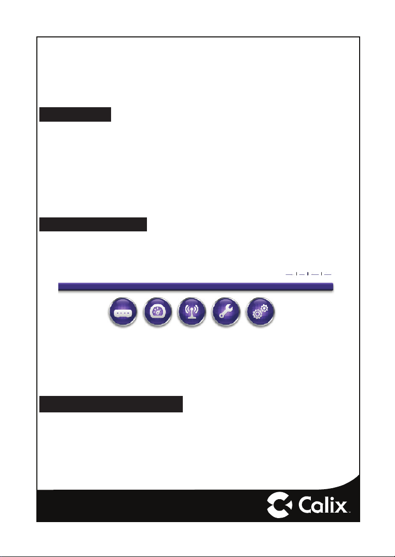
Status Quick Start Wireless Utilities Advanced
Home Logon AboutHelp
3. Enter the credentials provided on the label shipped inside the GigaHub box.
4. Navigate to the Quick Start Menu and set-up the following:
a. Choose how to connect to the Internet
b. Set the local time zone (may be automatically set by network)
For more information about device provisioning from the EWI, refer to the GigaHub User’s Guide.
Frequently Asked Questions
Q: How do I reset the device without having to unplug the unit?
A: If the RESET button is depressed for less than 5 seconds, it resets the unit using the current
confi guration settings.
Q: How do I reset the device back to factory settings?
A: Pressing the RESET button on the back of the unit for at least 5 seconds, or access the “Restore
Defaults” reset button located in the “Utilities” section of the Embedded Web Interface.
— 4 —
Page 5

Q: How does the WPS button work?
A: Pressing the WPS button broadcasts the GigaHubs credentials (network password) to other
WPS capable devices for a period of 2 minutes, allowing these devices to gain access to the
wireless network.
Q: Is the Wireless radio on by Default?
A: Yes.
Q: Is Wireless Security on by Default?
A: Yes, unit is set with WPA2 Key Wi-Fi security type and login/password credentials that are
printed on the inventory label and the product label affi xed to the device.
Q: What if the User Name or login keys are forgotten?
A: Try setting up the wired connection and confi guring the wireless encryption again.
Press the reset button of the wireless router for at least fi ve seconds.
Device reverts to factory default settings
Custom confi guration options (such as SSID names) are reset as well.
Q: My Wi-Fi signal strength is lower than I expected?
A: A wireless signal degrades with distance and obstructions. Common signal impairments
include walls, ceilings, metal, concrete, cinder blocks, fl uorescent lights, microwaves, furniture,
etc. While the 823G has been optimized to provide wireless coverage for most applications,
there may be dependencies based on the location where the device is installed. Please contact your service provider for troubleshooting assistance.
Q: What mounting options are available for installing the 823G?
A: The 823G should be installed using the tabletop stand or wall mount bracket to ensure best
Wi-Fi performance and proper fi ber optic cable management. The 823G can be installed in a
fl at orientation on a desktop independent of the tabletop stand. Please ensure that the fi ber op-
tic cable can be properly routed to the device without excessive bends or pinching of the cable.
Q: What do I do if I cannot log on to the 823G gateway?
A: Contact your service provider.
Q: Who do I contact for service and support?
A: Contact your service provider.
Safety Information
The 823G GigaHub is a highly sophisticated electronic device. To get the most out of it, be sure to read the following about product care, safety and effi cient use.
• Treat the product with care, keep it in a clean and dust free environment.
• Do not expose the GigaHub to liquid, moisture or humidity.
• Do not expose the GigaHub to extreme high or low temperatures; refer to the topic Environmental Condi-
tions for more detailed information.
• Do not expose the GigaHub to open fl ames or lit tobacco products.
• Do not drop, throw, or try to bend the product, since rough treatment could damage it.
• Do not use this product near water, for example, near a bathtub, washbowl, kitchen sink, laundry tub, in a
wet basement, or near a swimming pool.
— 5 —
Page 6

• Do not attempt to disassemble the GigaHub. A broken warranty seal will void the warranty. The product
does not contain consumer-serviceable components. Only Certifi ed Service Centers should perform service.
• Do not use any accessories other than those approved by the manufacturer or your service provider. Use
of non-original or non-approved accessories may result in loss of performance, damage to the product, fi re,
electric shock or injury, and may violate regulations. The warranty does not cover product failures that have
been caused by use of non-original or non-approved accessories.
L’information sur la sécurité
Le 823G GigaHub est un appareil électronique sophistiqué. Pour tirer le meilleur parti de celui-ci, assurez-vous de
lire ce qui suit sur les soins, la sécurité et l’utilisation effi cace du produit.
• Traitez le produit avec soin, gardez-le dans un environnement propre et exempt de poussière.
• N’exposez pas le GigaHub au liquide ou à l’humidité.
• N’exposez pas le GigaHub à des températures extrêmes élevées ou basses. Se référer à la partie Conditions environnementales pour des informations plus détaillées.
• N’exposez pas le GigaHub à des fl ammes nues ou à des produits du tabac allumés.
• Ne laissez pas tomber votre appareil, ne le lancez pas et ne tentez pas de le plier, car un traitement brutal
pourrait l’endommager.
• N’utilisez pas ce produit près de l’eau, par exemple, près d’une baignoire, un lavabo, un évier ou un lavoir,
en sous-sol humide, ou près d’une piscine.
• N’essayez pas de démonter le GigaHub. Un sceau de garantie brisé annule la garantie. Le produit ne
contient pas de pièces réparables par le consommateur. Seulement les centres de service agréés devraient
effectuer des réparations.
• N’utilisez pas d’accessoires autres que ceux approuvés par le fabricant ou votre fournisseur de services.
L’utilisation d’accessoires non originaux ou non approuvés peut entraîner une perte de performance, des
dommages au produit, un incendie, des chocs électriques ou des blessures et peut contrevenir aux règlements. La garantie ne couvre pas les pannes provoquées par l’utilisation d’accessoires non standards ou
non approuvés.
Potentially Explosive Atmosphere
Do not use the GigaHub in an area where a potentially explosive atmosphere exists.
Atmosphère potentiellement explosive
N’utilisez pas le GigaHub dans un endroit où existe une atmosphère potentiellement explosive.
Intended Use
This product is classifi ed as telecommunication equipment not intended for direct purchase by the public.
This product is designed and approved for use in an indoor location only.
CAUTION! Use of any controls, adjustments, or procedures other than those specifi ed
herein may result in hazardous radiation exposure.
!
Utilisation prévue
Ce produit est classé comme équipement de télécommunication non destiné à l’achat direct par le public.
Ce produit est conçu et approuvé pour utilisation en intérieur uniquement.
MISE EN GUARDE ! L’utilisation de contrôles, réglages ou procédures autres que ceux
spécifi és dans ce manuel peut entraîner une exposition dangereuse à des rayonnements.
!
— 6 —
Page 7

Power Supply
Ensure that a suitable AC power outlet is situated near the GigaHub and easily accessible.
Connect the power supply cord only to the AC power outlet that meets the specifi cations marked next to the appli-
ance AC power inlet on the GigaHub.
Never alter the AC power cord. If necessary have the correct outlet installed by a qualifi ed electrician or call your
service provider for assistance.
To reduce the risk of damage to the electric cord, remove it from the outlet by holding onto the AC power adapter
rather than the cord. Make sure the cord is positioned so that it will not be stepped on, tripped over or otherwise
subjected to damage or stress.
WARNING! Do not use any other power adapter except the one that accompanies this unit
or a power supply identifi ed in the list below. Use of another adapter could result in damage
to the unit. To prevent electrical shock, please do not open the cover. The following power
adapter is qualfi ed for use with this GigaHub.
823G-1 Power Supply Specifi cation
This GigaHub must be powered by Amigo
AMS157-1202000FU or equivalent UL Listed LPS power source rated at:
Input: 90-264 VAC, 47/63 Hz, 1A,
Output: Nominal 12 VDC, 2A Maximum, 24W
823G-2 Power Supply Specifi cation
This GigaHub must be powered by Amigo
AMS157-1202000FV or equivalent UL Listed LPS power source rated at:
Input: 90-264 VAC, 47/63 Hz, 1A,
Output: Nominal 12 VDC, 2A Maximum, 24W
RF Port Grounding
Metallic coaxial cable shielding, if used, must be connected to earth ground in accordance with ANSI/NFPA 70.
RF Port Type
The RF port on the 823G GigaHub must be directly connected to a TV or a Video device inside the same building.
The RF cable is not to be routed outside the building or to a cable distribution system. This port is considered a
Safety Extra Low Voltage (SELV) port.
Alimentation électrique
• Assurez-vous qu’une prise de courant C.A. appropriée est située près du GigaPoint et qu’elle soit facile
d’accès.
• Connectez le câble d’alimentation uniquement à une prise de courant qui correspond aux spécifi cations
indiquées à côté de l’entrée d’alimentation du GigaHub.
• Ne modifi ez jamais le câble d’alimentation. Si nécessaire, faîtes installer la bonne prise de courant par un
électricien qualifi é ou Contactez votre prestataire de services pour assistance.
• Pour réduire le risque de dommage au câble électrique, retirez-le de la prise de courant en tenant l’adaptateur secteur plutôt que le câble. Assurez-vous que le câble est positionné de manière à éviter qu’il soit
possible de marcher ou trébucher dessus, ou de l’endommager.
Attention ! N’utilisez pas d’autre adaptateur secteur que celui qui accompagne cet
appareil ou une alimentation électrique autre que celle identifi ée dans la liste ci-dessous.
L’utilisation d’un autre adaptateur pourrait endommager l’appareil. Pour éviter les chocs
électriques, n’ouvrez pas le couvercle. L’adaptateur électrique suivant est qualifi é pour être
utilisé avec le GigaHub.
— 7 —
Page 8

L’adaptateur électrique suivant est qualifi é pour être utilisé avec le GigaHub
Specifi cations de l’alimentation du 823G-1
Ce GigaHub doit être alimenté par un adapteur Amigo AMS157-1202000FU ou une source d’ali-
mentation équivalente certifi ée UL LPS de capacité:
Entree: 90-264 VCA, 47/63 Hz, 1A,
Sortie: Valeur nominale 12 VDC, 2A Maximum, 24W
Specifi cations de l’alimentation du 823G-2
L’adaptateur électrique suivant est qualifi é pour être utilisé avec le GigaHub
Ce GigaHub doit être alimenté par un adapteur Amigo AMS157-1202000FV ou une source d’ali-
mentation équivalente certifi ée UL LPS de capacité:
Entree: 90-264 VCA, 47/63 Hz, 1A,
Sortie: Valeur nominale 12 VDC, 2A Maximum, 24W
Mise à la terre du port RF
Le blindage métallique des câbles coaxiaux, s’il est utilisé, doit être relié à la terre conformément à la norme ANSI
/ NFPA 70.
Type de port RF
Le port RF du GigaHub 823G doit être directement connecté à un téléviseur ou à un appareil vidéo dans le même
bâtiment. Le câble RF ne doit pas être acheminé à l’extérieur du bâtiment ou à un système de distribution par
câble. Ce port est considéré comme un port de très basse tension de sécurité (SELV).
Class 1 Laser Device
WARNING! Optical Safety for Fiber Optic Modules. Never look at the transmit laser
while it is powered on. Never look into the fi ber optic port when the device is powered on.
Never look into the end of the fi ber optic cable at any time.
Appareil laser de Classe 1
Attention ! Sécurité optique pour les modules de fi bre optique. Ne regardez jamais
l’émetteur laser lorsqu’il est sous tension. Ne regardez jamais dans le port de fi bre optique
lorsque l’appareil est sous tension. Ne regardez jamais dans l’extrémité du câble de fi bre
optique.
Children
Do not allow children to play with the GigaHub. It contains small parts that could become detached and create a
choking hazard.
Environmental Conditions
Maximum environmental values during use:
Temperature: 0° C to +40° C (32° to 104° F), Humidity: 5% - 95% RH, non-condensing
RoHS Compliance
This 823G GigaHub meets the requirements detailed in the European RoHS Directive (2011/65/EU).
— 8 —
Page 9

WEEE Directive
Requirements according to WEEE directive (2012/19/EU)
Disposal of old electrical and electronic equipment (Applicable in the European
countries with separate collection systems).
This symbol on the product indicates that this product shall not be treated as
household waste. Instead it shall be handed over to the applicable collection point
for the recycling of electrical and electronic equipment. By ensuring this product
is disposed of correctly, you will prevent potential negative consequences for the
environment and human health, which could otherwise be caused by inappropriate waste handling of this product. The recycling of materials will help to conserve
natural resources. Calix offers take-back and recycling services for products in
many locations around the world. The customers are advised to contact the local
Calix representative for further information.
Federal Communications Commission (FCC)
INTERFERENCE STATEMENT
This equipment has been tested and found to comply with the limits for a Class B digital device, pursuant to Part 15 of
the FCC Rules. These limits are designed to provide reasonable protection against harmful interference in a residential installation. This equipment generates, uses and can radiate radio frequency energy and, if not installed and used
in accordance with the instructions, may cause harmful interference to radio communications. However, there is no
guarantee that interference will not occur in a particular installation. If this equipment does cause harmful interference
to radio or television reception, which can be determined by turning the equipment off and on, the user is encouraged
to try to correct the interference by one of the following measures:
• Reorient or relocate the receiving antenna.
• Increase the separation between the equipment and receiver.
• Connect the equipment into an outlet on a circuit different from that to which the receiver is connected.
• Consult the dealer or an experienced technician for help.
NON-MODIFICATIONS STATEMENT
Any changes or modifi cations not expressly approved by the party responsible for compliance could void the user’s
authority to operate this equipment.
CAUTION: This device complies with Part 15 of the FCC Rules. Operation is subject to the following two conditions:
(1) This device may not cause harmful interference, and
(2) This device must accept any interference received, including interference that may cause undesired
For product, available in the USA/Canada market, only channel 1~11 can be operated. Selection of other channels is
not possible.
This device and its antenna(s) must not be co-located or operating in conjunction with any other antenna or transmitter except in accordance with FCC multi-transmitter product procedures.
ADDITIONAL CONSIDERATIONS
The country code selection is for non-US models only and is not available on any US models. Per FCC regulations, all
Wi-Fi products marketed in the US must be fi xed to US operational channels only.
FCC RADIATION EXPOSURE STATEMENT
This equipment complies with the FCC RF radiation exposure limits set forth for an uncontrolled environment. This
equipment should be installed and operated with a minimum distance of 20cm between the radiator and any part of
your body.
operation.
— 9 —
Page 10

Industry Canada Requirements - English
The manufacturer declares that this product is in conformity with the requirements and other relevant provisions of
the following Canadian standards:
• CAN ICES-3 (B)/NMB-3(B)
• This device complies with Industry Canada license-exempt RSS standard(s). Operation is subject to the
following two conditions:
(1) This device may not cause interference, and
(2) This device must accept any interference, including interference that may cause undesired operation of
IMPORTANT NOTE - IC RADIATION EXPOSURE STATEMENT: This equipment complies with IC RSS-102 radiation exposure limits set forth for an uncontrolled environment. This equipment should be installed and operated with a
minimum distance of 20cm between the radiator & your body.
the device.
Industrie Canada Exigences - français
Le fabricant déclare que ce produit est conforme aux exigences et aux autres dispositions pertinentes des normes
canadiennes:
• CAN-ICES-3 (B)/NMB-3(B)
• Le present appareil est conforme aux CNR d’Industrie Canada applicables aux appareils radio exempts
de licence. L’exploitation est autorisee aux deux conditions suivantes :
(1) l’appareil ne doit pas produire de brouillage, et
(2) l’utilisateur de l’appareil doit accepter tout brouillage radioelectrique subi, meme si le brouillage est
REMARQUE IMPORTANTE - EXPOSITION AUX RADIATIONS IC: Cet équipement est conforme aux limites
d’exposition aux rayonnements IC établies pour un environnement non contrôlé. Cet équipement doit être installé et
utilisé avec un minimum de 20cm de distance entre la source de rayonnement et votre corps.
susceptible d’en compromettre le fonctionnement.
For Radio Equipment Only
You must set the correct country code with the set WLAN country-code command to avoid violating
local radio spectrum laws. This command sets the selectable channel range and transmit power level
so that a WLAN connection can be established. For more information about country codes, see the
This device complies with the essential requirements of the Radio Equipment directive: 2014 / 53 / EU. The following
test methods have been applied to prove presumption of conformity with the essential requirements of the Radio
Equipment directive: 2014 / 53 / EU:
EN 300 328 (2.4 GHz), EN 62311:2008, EN 50385, EN 301489-1, EN 301489-17, IEC 60950-1, IEC 60825-1.
RADIATION EXPOSURE STATEMENT
The minimum distance between the user and/or any bystander and the radiating structure of the transmitter is 20 cm.
Usage Notes
hardware guide for your device.
FREQUENCIES MAX POWER INDOOR/OUTDOOR
2400-2483.5 100 mW Indoor
NOTICE OF WIRELESS RADIO LAN USAGE IN THE EUROPEAN COMMUNITY
BE BG CZ DK
DE EE IE EL
ES FR HR IT
CY LV LT LU
HU MT NL AT
PL PT RO SE
SK FI SE UK
UISNOTR
CH
• To remain in conformance with European National spectrum usage regulations, frequency and channel
limitations will be applied on the products per the country where the equipment will be deployed.
This device is a 2.4 GHz wideband transmission system (transceiver), intended for use in all
EU member states and EFTA countries, except in France where restrictive use applies. This
device may not be used for setting up outdoor radio links in France and in some areas, the
RF output power may be limited to 10 mW EIR P in the frequency range of 2454 –2483.5
MHz. For detailed information, the end-user should contact the national spectrum authority
in France.
This equipment may be operated in AL, AD, BE, BG, DK, DE, FI, FR, GR, GW, IS, IT, HR, LI,
LU, MT, MK, MD, MC, NL, NO, AT, OL, PT, RO, SM, SE, RS, SK, ES, CI, HU, CY
— 10 —
Page 11

Declaration of Conformity
Language Declaration of Conformity
С настоящото Calix Inc. Това декларира тази Wireless Broadband Терминал за достъп е в съответствие
български [Bulgarian]
hrvatski [Croatian]
English
český [Czech]
Deutsch [German]
Eesti [Estonian]
español [Spanish]
Ελληνική [Greek]
français [French]
Italiano [Italian]
Latvijas [Latvian]
Lietuvos [Lithuanian]
с Директива 2014/53 / ЕС.
Пълният текст на ЕС декларацията за съответствие е достъпна онлайн от сайта на декларациите на
Calix (https://www.calix.com/declarations).
OOvime Calix Inc. To izjavljuje ovaj bežični širokopojasni pristup terminala u skladu s Direktivom 2014/53 /
EU.
Puni tekst izjave o sukladnosti za EU je dostupan online od kaliks web deklaracije (https://www.calix.com/
declarations).
Hereby, Calix Inc. declares that this Broadband wireless Access Terminal is in compliance with Directive
2014/53/EU.
The full text of the EU declaration of conformity is available online from the Calix Declarations site (https://
www.calix.com/declarations).
Tím Calix Inc. Která deklaruje toto Wireless Broadband Access Terminal je v souladu se směrnicí 2014/53 /
EU.
Úplné znění EU prohlášení o shodě je k dispozici online na webové stránce prohlášení kalichu (https://www.
calix.com/declarations).
Hiermit Calix Inc. Das erklärt der Wireless Broadband Access Terminal in Übereinstimmung mit der Richtlinie
2014/53 / EU.
Der vollständige Wortlaut der EU-Konformitätserklärung wird online von den Calix Website Erklärungen zur
Verfügung (https://www.calix.com/declarations).
Käesolevaga Calix Inc. See kinnitab seda traadita lairibaühenduse Terminal on kooskõlas direktiivi 2014/53
/ EL.
Tervikteksti ELi vastavusdeklaratsiooni on saadaval võrgus Calix veebilehel deklaratsioonid (https://www.calix.
com/declarations).
Por la presente, Calix Inc. Que declara esta Terminal de banda ancha de acceso inalámbrico está en conformidad con la Directiva 2014/53 / UE.
El texto completo de la declaración de conformidad de la UE está disponible en línea desde el sitio web
Declaraciones de Calix (https://www.calix.com/declarations).
Δια του παρόντος, Calix Inc. Αυτό δηλώνει αυτό το Wireless Terminal Ευρυζωνική πρόσβαση είναι σε
συμμόρφωση με την οδηγία 2014/53 / ΕΕ.
Το πλήρες κείμενο της δήλωσης συμμόρφωσης ΕΕ είναι διαθέσιμα στο διαδίκτυο από την ιστοσελίδα Calix
Δηλώσεις (https://www.calix.com/declarations).
Par la présente, Calix Inc. Cet accès qui déclare haut débit sans fi l terminal est conforme à la directive
2014/53 / UE.
Le texte intégral de la déclaration de conformité C’est disponible en ligne à partir des déclarations de site
Calix (https://www.calix.com/declarations).
Con la presente, Calix Inc. Che dichiara questo terminale di accesso wireless a banda larga è conforme alla
Direttiva 2014/53 / UE.
Il testo integrale della dichiarazione di conformità UE è disponibile online dal sito Dichiarazioni Calix (https://
www.calix.com/declarations).
Ar šo, Calix Inc. Tas paziņo, šis bezvadu platjoslas piekļuves termināls atbilst Direktīvas 2014/53 / ES.
Pilns teksts ES atbilstības deklarācijas ir pieejama tiešsaistē no Calix tīmekļa deklarācijas (https://www.calix.
com/declarations).
Šiuo dokumentu Calix Inc Tai deklaruoja tai bevielės plačiajuostės prieigos terminalas atitinka Direktyvos
2014/53 / ES.
Visą tekstą ES atitikties deklaraciją galima rasti internete nuo CALIX svetainės deklaracijas (https://www.calix.
com/declarations).
— 11 —
Page 12

Language Declaration of Conformity
Ezáltal Calix Inc. Hogy kijelenti ezt Wireless Broadband Access Terminal irányelvnek megfelelően 2014/53
Magyar [Hungarian]
Polski [Polish]
português [Portuguese]
român[Romanian]
slovenščina[Slovenian]
slovenský [Slovak]
/ EU.
A teljes szöveg az EU-megfelelőségi nyilatkozat elérhető online az Calix honlapján Nyilatkozatok (https://
www.calix.com/declarations).
Niniejszym, Calix Inc. Deklaruje, że ten Szerokopasmowy dostęp bezprzewodowy terminal jest zgodny z
dyrektywą 2014/53 / UE.
Pełny tekst deklaracji zgodności UE jest dostępna on-line ze strony internetowej calix deklaracji (https://www.
calix.com/declarations).
Por este meio, Calix Inc. Que declara esta Terminal de Acesso de Banda Larga sem fi os está em conformi-
dade com a Directiva 2014/53 / UE.
O texto completo da declaração UE de conformidade está disponível online a partir de declarações do Web
site da Calix (https://www.calix.com/declarations).
Prin prezenta, Calix Inc poate declara que acces de bandă largă fără fi r Terminal este în conformitate cu
Directiva 2014/53 / UE.
Textul integral al declarației de conformitate UE este disponibilă online din calix declarațiile site-ul (https://
www.calix.com/declarations).
S tem lahko calix Inc. razglasi que širokopasovnega brezžičnega dostopa Terminal je v skladu z Direktivo
2014/53 / EU.
Celotno besedilo izjave EU o skladnosti je na voljo na spletu na spletni strani izjavami calix (https://www.calix.
com/declarations).
Týmto Calix Inc. môže vyhlásiť tento que Broadband Wireless Access Terminal je v súlade so smernicou
2014/53 / EÚ.
Úplné znenie vyhlásenia o zhode EÚ je k dispozícii online na webovej stránke vyhlásenie kalichu (https://
www.calix.com/declarations).
License Information
Open Source Software Utilization Notice
The 823G GigaHub uses Open Source Software Programs. Such software programs are made available subject to
certain third party terms and conditions.
The fact that you are about to begin using or have purchased this product requires that you be informed of the use
of these software packages and or libraries and in some cases, the third party terms and conditions applicable to
such software. This information can be found on the manufacturer’s support portal. Refer to the appropriate software
release notes for additional information on Open Source Software Programs used by this product.
— 12 —
 Loading...