

Page 1
USER’S
GUIDE
AreaTake-Off ToolandDigitizing System
Model
#6260
Page 2

TABLE OF CONTENTS
INTRODUCTION . . . . . . . . . . . . . . . . . . . . . . . . . . . . . . . . . . . . . .1
SETUP . . . . . . . . . . . . . . . . . . . . . . . . . . . . . . . . . . . . . . . . . . . . . . . .2
PACKAGE CONTENTS . . . . . . . . . . . . . . . . . . . . . . . . . . . . . . . . . . .2
RIGHT-HAND ASSEMBLY . . . . . . . . . . . . . . . . . . . . . . . . . . . . . . .4
LEFT-HAND ASSEMBLY . . . . . . . . . . . . . . . . . . . . . . . . . . . . . . . . .6
GETTING STARTED . . . . . . . . . . . . . . . . . . . . . . . . . . . . . . . . . . . . .8
KEY DEFINITIONS . . . . . . . . . . . . . . . . . . . . . . . . . . . . . . . . . . . 10
MEASURING KEYS . . . . . . . . . . . . . . . . . . . . . . . . . . . . . . . . . . . .10
FUNCTION KEYS . . . . . . . . . . . . . . . . . . . . . . . . . . . . . . . . . . . . . 12
SETUP KEYS . . . . . . . . . . . . . . . . . . . . . . . . . . . . . . . . . . . . . . . . .14
USING THE ULTRA SCALE MASTER PRO . . . . . . . . . . . . . 16
UNDERSTANDING THE LCD . . . . . . . . . . . . . . . . . . . . . . . . . . . . . 16
BUILT-IN SCALES . . . . . . . . . . . . . . . . . . . . . . . . . . . . . . . . . . . . . 17
SHAPES AND DEFINITIONS . . . . . . . . . . . . . . . . . . . . . . . . . . . . . 18
MEASURING POLYLINES . . . . . . . . . . . . . . . . . . . . . . . . . . . . . . .20
MEASURING SIMPLE POLYGONS . . . . . . . . . . . . . . . . . . . . . . . .22
MEASURING TAKE-OUTS . . . . . . . . . . . . . . . . . . . . . . . . . . . . . .24
MEASURING COMPLEX POLYGONS . . . . . . . . . . . . . . . . . . . . . .26
MEASURING IRREGULAR SHAPES . . . . . . . . . . . . . . . . . . . . . . .28
MEASURING ARCS AND CIRCLES . . . . . . . . . . . . . . . . . . . . . . . .30
MEASURING ARCS . . . . . . . . . . . . . . . . . . . . . . . . . . . . . . . . . . .32
MEASURING 3-POINT CIRCLES . . . . . . . . . . . . . . . . . . . . . . . . . .34
CUSTOM SCALES . . . . . . . . . . . . . . . . . . . . . . . . . . . . . . . . . . . .36
SETTING A MEASURED CUSTOM SCALE . . . . . . . . . . . . . . . . . . .36
SETTING AN ENTERED CUSTOM SCALE (IMPERIAL MODE) . . . . .38
SETTING A HEIGHT . . . . . . . . . . . . . . . . . . . . . . . . . . . . . . . . . . .39
UNITS OF MEASUREMENT . . . . . . . . . . . . . . . . . . . . . . . . . . . . .40
DIGITIZER MODE . . . . . . . . . . . . . . . . . . . . . . . . . . . . . . . . . . . .41
PC INTERFACE . . . . . . . . . . . . . . . . . . . . . . . . . . . . . . . . . . . . . . .42
SENDING VALUES TO YOUR PC (PC SEND) . . . . . . . . . . . . . . . . .43
PREFERENCES . . . . . . . . . . . . . . . . . . . . . . . . . . . . . . . . . . . . . . .45
APPENDIX A . . . . . . . . . . . . . . . . . . . . . . . . . . . . . . . . . . . . . . . .47
ACCURACY/ERRORS/AUTO SHUT-OFF. . . . . . . . . . . . . . . . . . . . .47
APPENDIX B . . . . . . . . . . . . . . . . . . . . . . . . . . . . . . . . . . . . . . . .47
RESET . . . . . . . . . . . . . . . . . . . . . . . . . . . . . . . . . . . . . . . . . . . . .47
APPENDIX C . . . . . . . . . . . . . . . . . . . . . . . . . . . . . . . . . . . . . . . .48
SPECIFICATIONS . . . . . . . . . . . . . . . . . . . . . . . . . . . . . . . . . . . . .48
APPENDIX D . . . . . . . . . . . . . . . . . . . . . . . . . . . . . . . . . . . . . . . .48
REPAIR AND RETURN . . . . . . . . . . . . . . . . . . . . . . . . . . . . . . . . .48
Page 3
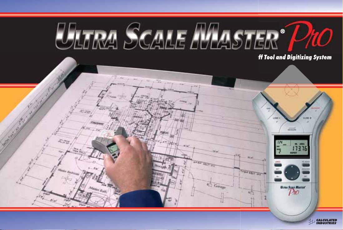
INTRODU CTION
The Ultra Scale Master Pro
has been specifi cally
desig ne d for r e sidenti a l
and light commerci a l
builders a nd contrac tor s
requir i ng a re a a nd
volume take-offs. Use
it for estimating project
materials a nd co sts, for
measuring, storing and
calculating perimeters,
areas, and volumes fr om
architectural plans and
other ty p es of sc a led
drawings. Use the
Ultra Scale Master Pro to
calculate t he a re a a nd
volume of irregular shapes;
it can also be used as a
digitizer. A PC interface
is included to enable data
and measurements to be
sent to PC applications.
The Ultra Scale Master Pro
may be used with or
without a PC.
USER’S GUIDE — 1
Page 4

SETUP
PACKAGE CONTENTS
Your package contain s the following piece s:
Four “AAA ” batteries
(already installed)
Female End Cap
Corner Connector
Long Refl ector Bar
Ultra Scale Master Pro
model 6260 (Puck)
USB Cable
2 — ULTRA SCALE MASTER
®
PRO
Page 5
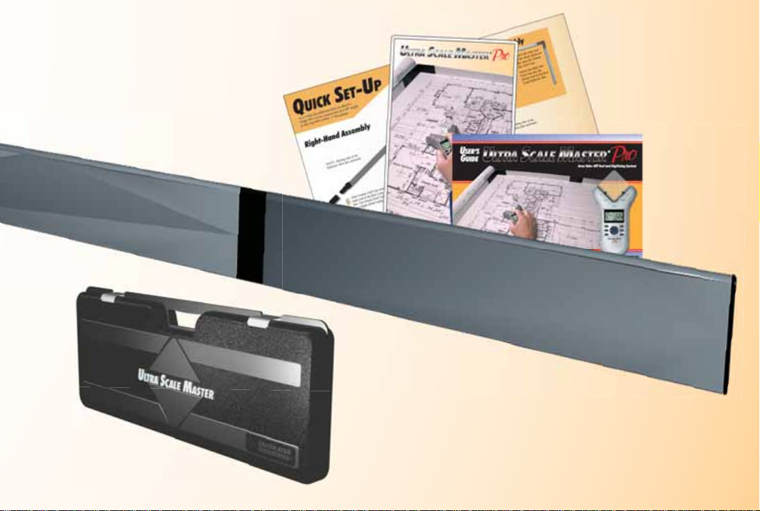
Long Refl ector Bar
Carrying Case
User’s Guide,
Quick Reference Guide,
and Quick Setup Sheet
Short Refl ector Bar
Male End Cap
USER’S GUIDE — 3
Page 6

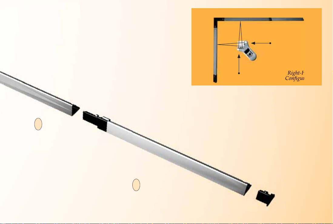
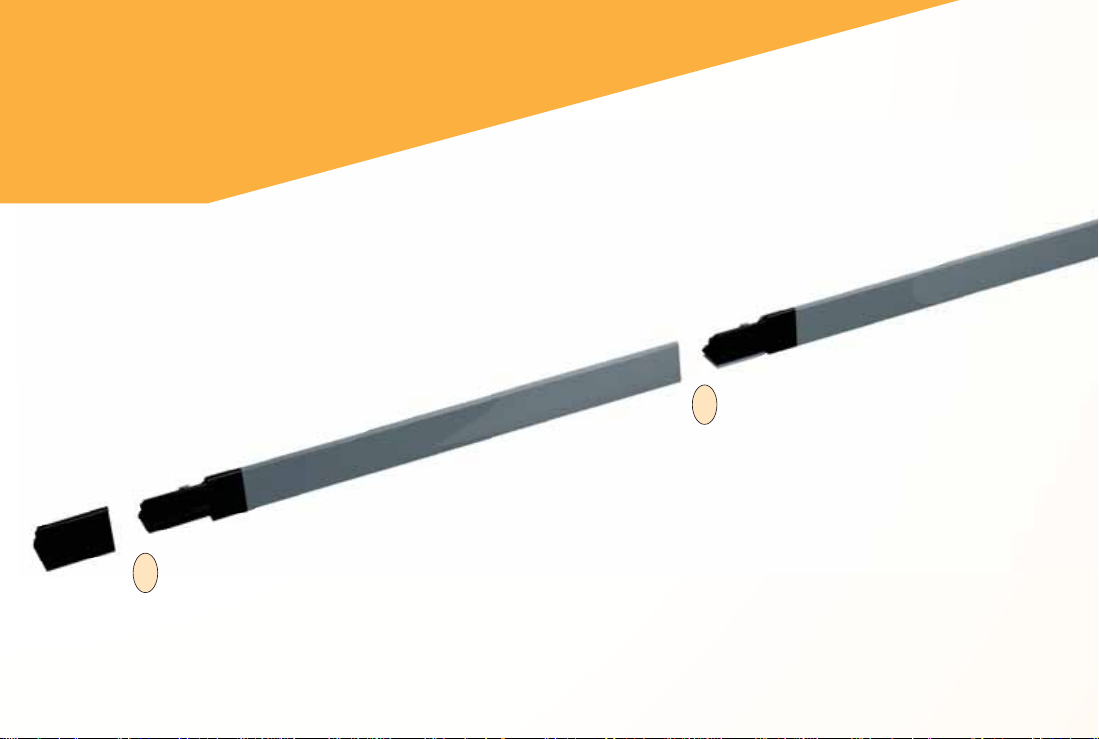
RIGHT-HAND ASSEMBLY
Assemble the refl e ctor bars
as shown. Align the corner
connector at a 90° angle at the
top left corner of the plans.
NOTE: Sloping side of the Refl ector
Bars face outward.
5. Slide Female End Cap onto the male end of the fi rst Long Refl ector Bar.
5
The Female End Cap is preinstalled for a Right-Hand confi guration.
2. Insert the male end of the second
2
Long Refl ector Bar into the female
end of the Corner Connector.
1. Insert the male end of the
1
Corner Connector into
the female end of the fi rst
Long Refl ector Bar.
4 — ULTRA SCALE MASTER
®
PRO
Page 7
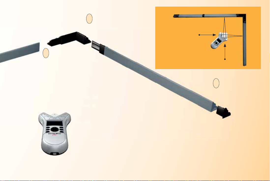
2nd Long Refl ecto r Bar Short Refl ector Bar
Right
Puck Arm
NOTE: Sloping side of the Refl ector
Bars face outward.
3. Insert the male
3
end of the Short
Refl ector Bar into
the female end of
the second Long
Refl ector Bar.
FINAL ASSEMBLY
The ultrasonic beams are sent from the left arm of
the Puck to the top bar, then refl ected back, and
from the right arm of the Puck to the side bar, then
refl ected back as shown above.
The Puck can be moved to any point within the bars
as long as the left arm remains parallel to the top bar
and the right arm remains parallel to the side bar as
shown above.
4. Insert the Male End Cap into
4
the female end of the Short
Refl ector Bar. The Male End
Cap is preinstalled for a RightHand confi guration.
1st Long Refl ector Bar
Left
Puck Arm
Right-Hand
Confi guration
USER’S GUIDE — 5
Page 8
LEFT-HAND ASSEMBLY
Assemble the refl ector bars as shown. Align
the corner connector at a 90° angle at the
top right corner of the plans.
4. Insert the male end of the Short Refl ector
4
Bar into the Female Bar End Cap.
NOTE: Sloping side of the Refl ector
Bars face outward.
5. Insert the the male end of
3
the second Long Refl ector
Bar into the female end of
the Short Refl ector Bar.
6 — ULTRA SCALE MASTER
®
PRO
Page 9
1. Insert male end
2
of the Corner
Connector into
the female end of
the second Long
Refl ector Bar.
1. Insert the male end of the
1
fi rst Long Refl ector Bar
into the female end of the
Corner Connector.
2nd Long Refl ector BarShort Refl ector Bar
1st Long Refl ector Bar
Left
Puck Arm
Left-Hand
Confi guration
Right
Puck Arm
4. Insert the Male Bar
5
End Cap into the
female end of the fi rst
Long Refl ector Bar.
FINAL ASSEMBLY
The ultrasonic beams are sent from the right arm of
the Puck to the top bar, then refl ected back, and from
the left arm of the Puck to the side bar, then refl ected
back as shown above.
The Puck can be moved to any point within the bars
as long as the right arm remains parallel to the top
bar and the left arm remains parallel to the side bar
as shown above.
USER’S GUIDE — 7
Page 10

GETTING STARTED
Once assem bly and se tup are complete, proceed with the following steps in
order to begin measuring.
1. When placing the bar s and secu ring the drawing, make sure that the
bars are at least 1" from the outermost me a surements.
2. It is essential that the ba r s r e m ain fi xed relative to the drawing’s
position. Scrib e a line to ma rk t he initia l lo c at ion of t he ba r s as a
reference point should t he bars shift.
3. The Puck should maintain a 45° ang le withi n the bars while measuring.
4. Ensure that the measuring sur face is fl at and smoot h. Ma ke sure there
are no folds, tears, or raise d areas of the pla ns.
5. Make sure there ar e no ob jects between the Puck a nd the bars. Th is
includes hands, arms, penci ls or pens, USB cable, cups, scale rulers, etc.
6. Make sure th at no air cur r e nt is blowi ng directly into the measu ring
area. Air blowi ng into the measu ring path ca n r e sult in no
measureme nt re ad ing.
7. To get accurate measurements, make sur e that the Puck and the bars are
close to the a mbient temperat ure of the work environment.
8 — ULTRA SCALE MASTER
®
PRO
Page 11
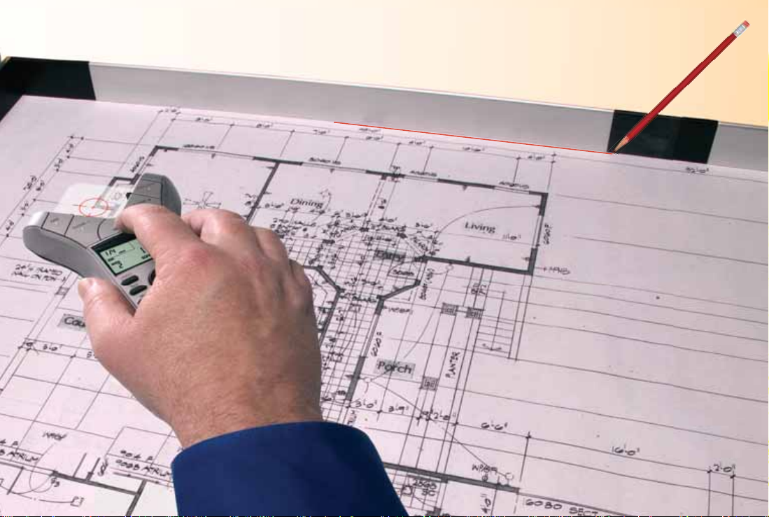
Right-Hand Confi guration Shown
USER’S GUIDE — 9
Page 12
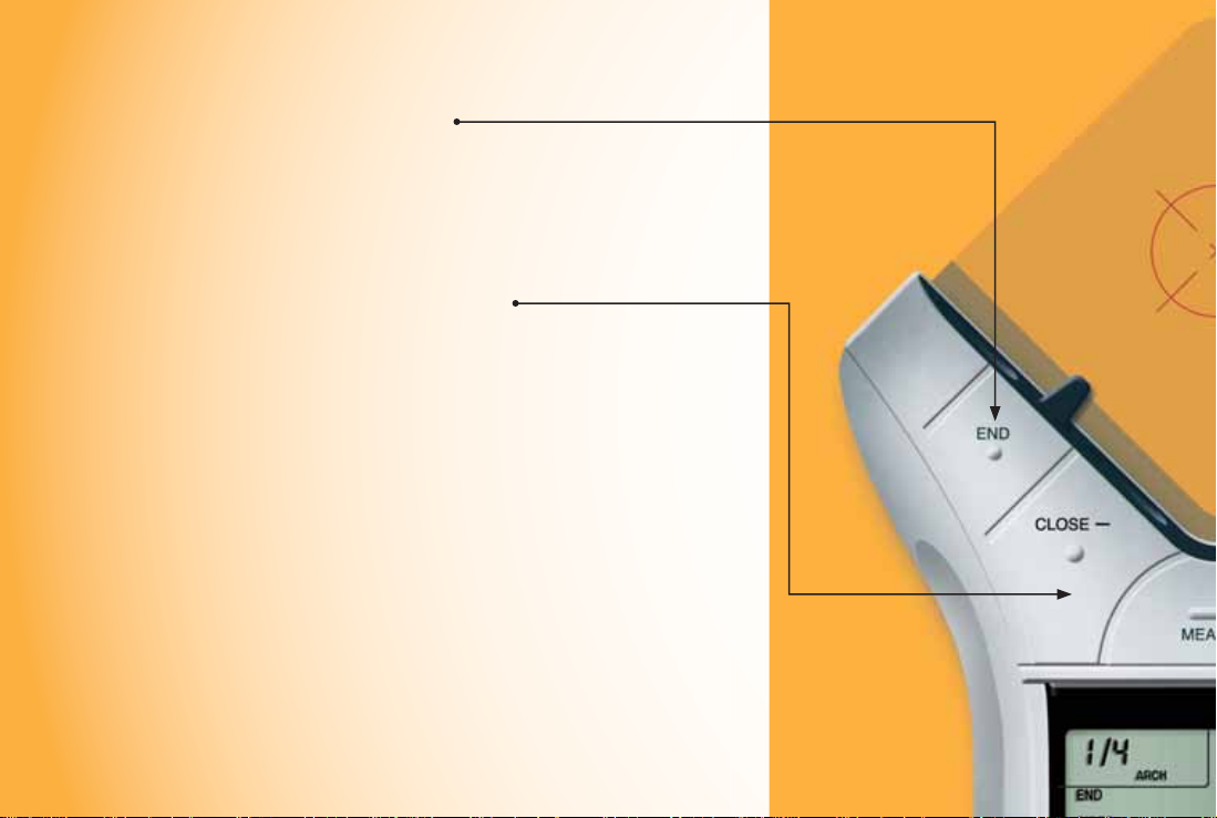
KEY DEFINITIONS
MEASURING KEYS
The keys shown are u s ed
for taking measure me nt s on
the blueprint and operat ing
the display (D-Pad key).
[END]
Ends polyli ne measurement,
displaying t he tot al perime ter.
Also ends the 2-Point Circle
measureme nt when measuring
a diameter, displaying the
circumference (perimeter).
[CLOSE — ]
Completes the Polygon or a
2-Point Ci rc le and displays the
calculated area. Results are
identifi ed as negat ive values.
When measuring a Polygon, this
key connect s the last measured
point to the sta rt point.
10 — ULTRA SCALE MASTER
®
PRO
Page 13
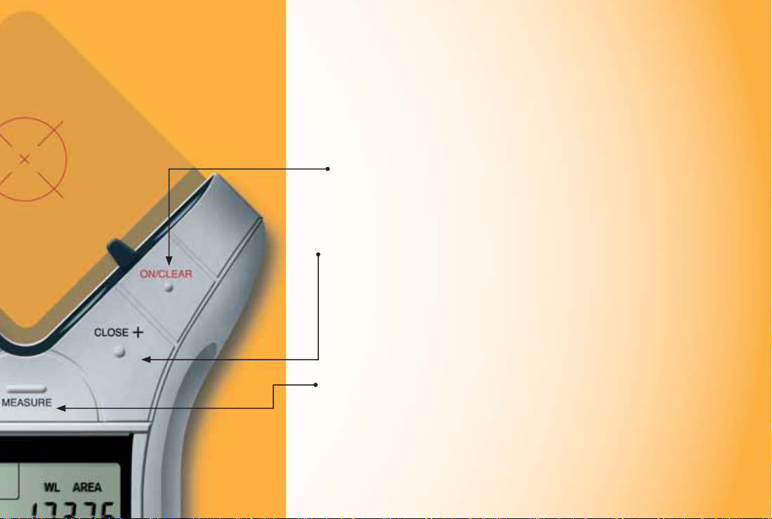
[ON/CLEAR]
Turns the u nit ON and clears
the display. Holding down t he
[ON/CLEAR] key for 1.5 s e cond s
also powers the unit off.
[CLOSE +]
Completes the Polygon or a
2-Point Ci rc le and displays the
calculated area. Results are
identifi ed as po sit ive values.
When measuring a Polygon, this
key connect s the last measured
point to the sta rt point.
[MEASURE]
Takes a measurement between
points.
Important Notes
regarding the
[ON/ CL EAR] key:
If [ON/CLEAR] is pressed
during measurement,
the last measured point
is undone and the
previous measurement is
displayed. A second press
of [ON/CLEAR] ends the
measurement (as if the
[END] key w as pressed) and
clears the main display.
During an Arc or Circle
measu rement, h o wever,
a second press of [ON/
CLEAR] exits the A r c
or Circle meas urement
mode, discarding any
measure d points.
Additionally, if a n error
message is displayed
during a mea surement,
pressing [ON/CLEAR]
clears the error message
and displays the previous
measure ment.
USER’S GUIDE — 11
Page 14
FUNCTION KEYS
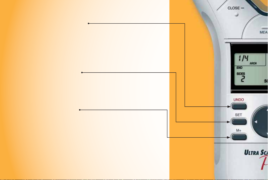
[UNDO]
Undoes the previous mea surement.
Allows you to undo the last 10
measurement s (if applicable) while in
measure mode. If a mea surement has
been close d or e nded, it wi ll undo the
close or end act ion and t he previous 9
measurements upon r epeated pre ss es of
[UNDO].
[SET]
Used in conjunction with the [HEIGHT]
and [SCALE] keys to set a Height or
Custom Scale (See Setting a Height and
Setting Custom Scale sections.) Also used to
access secondary functions (e.g., M-, MC).
[M+]
Adds the displayed value to accumulative
Memory (except when setting a Height or
Cus tom Scale).
[SET] [M+] (M—)
Subtracts the displayed value from the
accumulative Memory (except during a
measure ment).
12 — ULTRA SCALE MASTER
®
PRO
Page 15

[PC SEND]
When conne cted to a PC, sends the value
on the mai n display in decim al format to
the PC (see PC Interface section).
[ARC/ CIRC]
First press identifi es a new
measurement as an Arc, second
consecut ive press identi fi es it as a Circle.
Thre e points must be measu r ed for an
Arc; two points (diameter) or three points
must be measured for a c ircle. The
Ultra Scale Master Pro will auto-close
thre e-point Arc or Circle measureme nts.
[MR] (Memory Recal l)
First press displays the accumulative
Memory value; second consecutive
press displays Memory Count; thi rd
consecut ive press displays the Memory
Average. Repeated presse s cycle back
through this list of values.
[SET] [MR] (Memor y Clear)
Clears the accumulative Memory.
Directional Pad (D-PAD)
When a measurement is ended or closed,
pressing the D-Pad displays calcu l ated
values (disabled during mea suring). Also
used for set ting Preference s, Height, and
Cus tom Scales.
USER’S GUIDE — 13
Page 16
SETUP KEYS
The buttons shown below
are accessed by sliding the
bottom cover down until
they are revealed.
14 — ULTRA SCALE MASTER
®
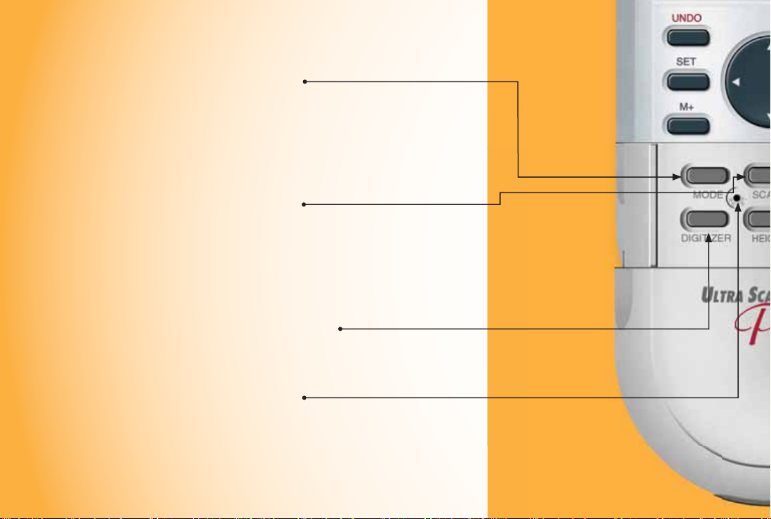
[MODE]
Used to select from the list of
available modes (see Built-In
Scales section).
[SET] [MODE]
Used to move back through the
list of available modes.
[SCALE]
Used to select from the list of
available scales within each
mode (see Built-In Scal e s section).
[SET] [SCALE]
Used to move back through the
list of available scales.
[DIGITIZER]
Sets unit into digitizing mode for
use with digitizing software (see
Digitizer Mode section).
[RESET]
Clears all values and resets all
setting s inclu d ing Preferenc e s
to their factory defaults. (Use the
end of a paperclip or something of
similar size to press.)
PRO
Page 17

[UNITS]
Used to select from the li st of
available units of mea surement
(see Units of Measurement section).
[SE T] [UN ITS]
Used to move back through
the list of avail able u nits of
measure ment.
[PREFS] (Preferences)
Accesses Preference settings (see
Preferences section).
[HEIGHT]
Displays stored height. Also
used in conjunction wit h [SET]
for sett ing a Height (see Setting a
Height section).
USER’S GUIDE — 15
Page 18

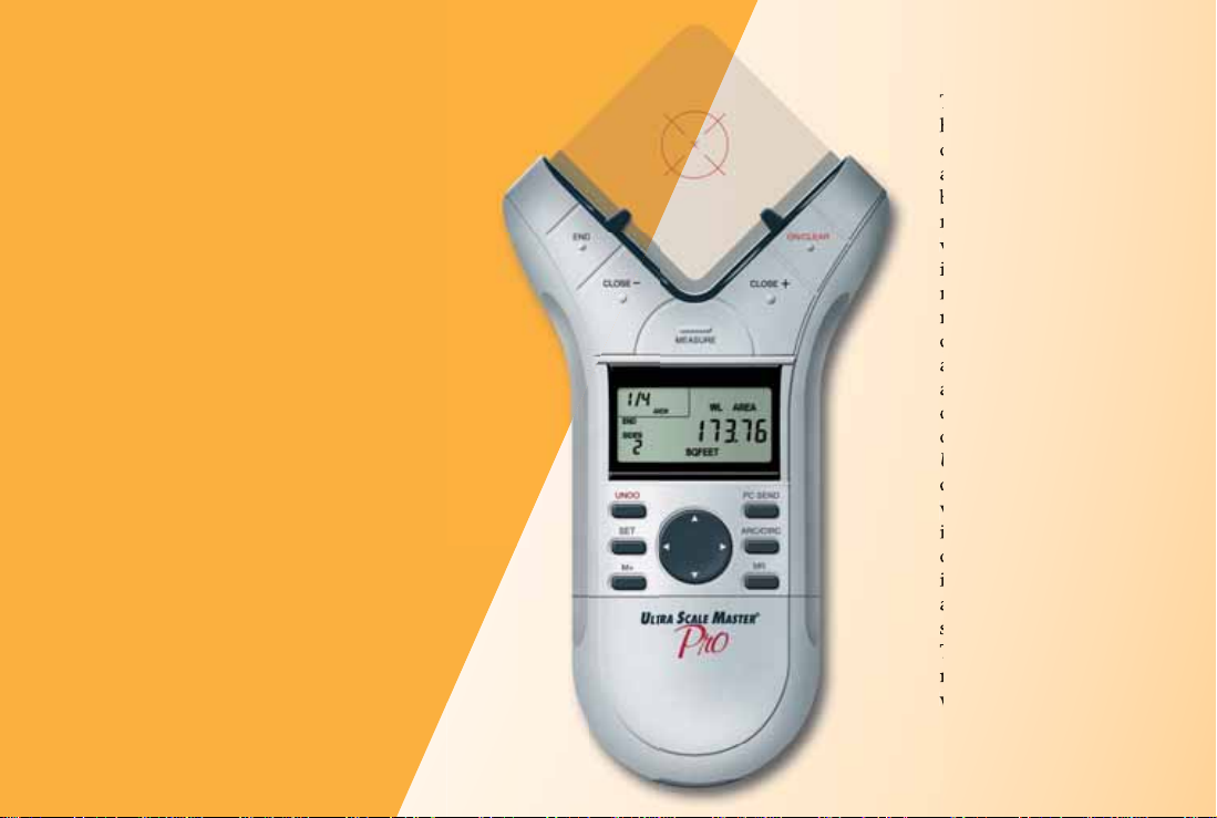
USING THE ULTRA SCALE MASTER PRO
UNDERSTANDING THE LCD
The selected Scale and Scale
Category or “Mode” are displayed
here. The Modes are as identifi ed:
• ARCH (Architectural)
• ENG I/ENG II (Engineering)
• CUST (Custom)
The Measure Status
and number of sides
are displayed here
(End or Closed are
displayed only when
a measurement has
been completed).
16 — ULTRA SCALE MASTER
®
PRO
The top legend displays
the following:
• SET
• CIRC (Circle)
• ARC
• M (Memory)
Low Battery Indicator
The area immediately
below the legend displays
the following:
• PER (Perimeter)
• WL (Wall)
• HT (Height)
• AREA
• (PC Connection)
Unit legend is
a description of
displayed values
(i.e. Square Feet, Inch)
This area,
often referred
to as the “Main
Display ,” is
used to display
values and
important
messages
Page 19

BUILT-IN SCALES
The following modes and scales
are available for selection using
the [MODE] and [SCALE] keys,
depending on whether the puck
is set to Imperial or Metric mode
using the [IMP/MET] switch
located on the back of the puck.
While in Imperial Mode, only the
Imperial Modes and Scales are
displayed. While in Metric Mode,
only Metric Modes and Scales are
displayed. However, all Imperial
and Metric units of measurement
are available within both modes.
When switching back and forth
between Imperial and Metric
modes, your settings within
each mode are held, including
Preference. The values stored in
[HEIGHT] and [M+] are cleared
when switching between Imperial
and Metric modes.
Note: W hile in Metr ic Mode, MET
will appear in the scale area of
the display to indicate that it is in
Metric Mode.
IMPERIAL
Modes Scales
Architectural (ARCH)
1 Foot =
Engineering I (ENGI)
1 Inch =
Engineering II (ENGII)
1 Inch =
1/4," 3/8," 1/2," 3/4," 1/1" (1"), 3/2" (1-1/2"), 2/1" (2"),
3/1" (3"), 4/1" (4"), 1/32," 1/16," 3/32," 1/8," 3/16"
10.0,' 20.0,' 30.0,' 40.0,' 50.0,' 60.0,' 83.3,' 100.0,' 166.6,'
200.0,' 250.0'
300.0,' 333.3,' 400.0,' 416.6,' 500.0,' 583.3,' 600.0,' 625.0,'
666.6,' 750.0,' 1,000,' 1,200,' 2,000,' 3,000'
METRIC
Modes Scales
Architectural
(MET ARCH)
Engineering I
(MET ENGI)
Engineering II
(MET ENGII)
1:50, 1:75, 1:1, 1:2, 1:3, 1:4, 1:5, 1:10, 1:20, 1:25, 1:30, 1:40
1:100, 1:125, 1:150, 1:200, 1:250, 1:300, 1:400, 1:500
1:1000, 1:1250, 1:1500, 1:1625, 1:2000, 1:2500, 1:5000,
1:6000, 1:10k, 1:12.5k, 1:20k, 1:25k, 1:50k
Note: Th e de fault Modes and Sc ales are listed fi rst and the rem aining Modes and Scales
are listed in the order that they appear on your Ultra Scale Master Pro.
USER’S GUIDE — 17
Page 20

SHAPES AND DEFINITIONS
The Ultra Scale Master Pro can measure Polylines, Polygons, regular or irregular shapes, Arcs and Circles based on the
following criteria:
• Only one shape can be measured at a time
• For a Polygon or Polyline only the last 64 measured sides
can be displayed when viewing side Lengths via the
D-Pad right [4] and left [3] arrows
• Arc measurements are assumed to be part of a Circle
Defi nitions and illustrations of some common shapes: Solution examples follow in the User’s Guide:
• In Arc or Circle Mode, measurements of ellipses or
irregular Arcs will result in incorrect calculations; the
resulting values are based on the assumption that the
points measured apply to a segment of a Circle
• An Arc or three-point Circle greater than 180° can also
be measured
POLYLINE:
A sequence
of connected
straight lines or
a single linear
distance like a
fence line
Note: Th e diag rams show n throughout the guide are not to scale and the displayed values are not representative of diagrams.
18 — ULTRA SCALE MASTER
®
PRO
POLYGON: A closed geometric fi gure bounded by three or more straight lines
1. Simple Po l y g on:
A Square, Rectangle
or T rian g le
2. Complex P o l y g on:
A multi-sided shape
that is not a Square,
Rectangle or Triangle
Page 21

IRREGULAR
SHAPE
An outline or
surface
confi guration
of a form
ARC:
A segment of a
curve
CIRCLE:
A plane curve
equidistant
from a fi xed
center
ILLEGAL SHAPE:
The Area and Volume can not be
calculated for a shape contain ing
bisecting lines. The Are a and Volume of
the shapes resulting fr om the bisecting
lines c an be calculated individually.
USER’S GUIDE — 19
Page 22

MEASURING POLYLINES
OPERATING SEQUENCE
1. Press the [ON/CLEAR] key twice to clear the display.
1
Place the crosshairs over the fi rst point and press the
[MEASURE] key.
2. Move to the second point and press the [MEASURE] key.
2
The display will show the Length of the fi rst line segment.
3. Move to the third point and pre ss t he [MEASURE]
3
key. The d isplay wil l show the accu mulated Leng t h
of the two measu red seg ment s.
2
1
20 — ULTRA SCALE MASTER
®
PRO
3 4
Page 23

4. Press the [END]
4
key. The tot al
Peri meter is
displayed. Once
a measurement i s
ended, press t h e
D-Pad down [6] to
display Perimeter,
Wall Area, and
stored Height.
Continuous pre sses
of the D-Pad down
[6] or up [5] will
scroll back a nd forth
through the values.
PERIMETER
WALL AREA*
HEIGHT*
*Wall Area and Height do not
display if a Height has not been
set. For this example, a Height of
eight Feet was used (See Setting
a Height section for instructions
on setting a Height).
5. Press the D-Pad
5
right [4] to display
the individual side
Lengths in sequential
order beginning with
side one. Repeated
presses of the D-Pad
left [3] will scr oll back
through the sides in
descending o rder.
SIDE 1
SIDE 2
USER’S GUIDE — 21
Page 24

MEASURING SIMPLE POLYGONS
OPERATING SEQUENCE
1. Press the [ON/CLEAR] key twice to clear the display.
1
Place the crosshairs over the fi rst point and press the
[MEASURE] key.
2. Move to the second point and press the [MEASURE] key.
2
The display will show the Length of the fi rst line segment.
3. Move to the third point and pre ss t he [MEASURE]
3
key. The d isplay wil l show the accu mulated Leng t h
of the two measu red seg ment s.
4. Move to the fourth point and press the [MEASURE] key.
4
The display wil l show the accu mulated Leng t h of the
thre e measu red s eg ments.
2
1
22 — ULTRA SCALE MASTER
®
PRO
3
4
5
Page 25

5. Press the [CLOSE+]
5
key. The tot al Area
is displayed. Once
a measurement i s
closed, press t he
D-Pad down [6] to
display Perimeter,
Wall Area, Volume
and stored Height.
Continuous presses
of the D-Pad down
[6] or up [5] will
scroll back and forth
through the values.
*Wall Area, Volume and
Height do not display
if a Height has not been
set. For this example, a
Height of eight Feet was
used (See Setting a Height
section for instructions
on setting a Height).
AREA
PERIMETER
WALL AREA*
VOLUME*
HEIGHT*
6. Press the D-Pad
6
right [4] to display
the individual side
Lengths in sequential
order beginning with
side one. Repeated
presses of the D-Pad
left [3] will scr oll back
through the sides in
descending o rder.
SIDE 1
SIDE 2
SIDE 3
SIDE 4
USER’S GUIDE — 23
Page 26

MEASURING TAKE-OUTS
OPERATING SEQUENCE
1. Press the [ON/CLEAR] key twice to clear the display.
1
Place the crosshairs over the fi rst point and press the
[MEASURE] key.
2. Move to the second point and press the [MEASURE] key.
2
The display will show the Length of the fi rst line segment.
3. Move to the third point and pre ss t he [MEASURE]
3
key. The d isplay wil l show the accu mulated Leng t h
of the two measu red seg ment s.
4. Move to the fourth point and press the [MEASURE] key.
4
The display wil l show the accu mulated Leng t h of the
thre e measu red s eg ments.
2
1
24 — ULTRA SCALE MASTER
®
PRO
3
4
5
Page 27

5. Press the [CLOSE+]
5
key. The tot al Area is
displayed.*
6. Press the [M+] key
6
to store the Area in
Memory , then repeat
1 4
steps 1 through 4 for
the Take-Out
*To do a Volume
Take-Out, press
the D - Pa d
down [6] or up
[5] until the
total Volume is
displa y ed.
AREA
7. Press the [CLOSE+]
7
key followed by the
[SET] then [M+]
keys. Now press the
[MR] key to display
the Adjusted Area.
Press the [SET] then
[MR] keys to clear
the Memory.
ADJUSTED AREA
6
25
Page 28

MEASURING COMPLEX POLYGONS
OPERATING SEQUENCE
1. Press the [ON/CLEAR] key twice to clear the display.
1
Place the crosshairs over the fi rst point and press the
[MEASURE] key.
5. Move to the fi fth point and press the [MEASURE] key.
5
6. Move to the sixth point and press the [MEASURE] key.
6
2. Move to the second point and press the [MEASURE] key.
2
3. Move to the third point and press the [MEASURE] key.
3
4. Move to the fourth point and press the [MEASURE] key.
4
2
3
4
1
26 — ULTRA SCALE MASTER
®
PRO
7. Move to the seventh point and press the [MEASURE] key.
7
8. Move to the eighth point and press the [MEASURE] key.
8
The accumulated Lengths of the seven measured
segments will be displayed.
6
7
5
8
9
Page 29

9. Press the [CLOSE+]
9
key. The tot al Area
is displayed. Once
a measurement i s
closed, press t he
D-Pad down [6] to
display Perimeter,
Wall Area, Volume
and stored Height.
Continuous presse s
of the D-Pad down
[6] or up [5] will
scroll back a nd forth
through the values.
*Wall Area, Volume and
Height do not display
if a Height has not been
set. For this example, a
Height of eight Feet was
used (See Setting a Height
section for instructions
on setting a Height).
AREA
PERIMETER
WALL AREA*
VOLUME*
10. Press the D-Pad
10
right [4] to display
the individual side
lengths in sequential
order beginning with
side one. Repeated
presses of the D-Pad
left [3] will scroll back
through the sides in
descending o rder.
SIDE 1
SIDE 2
SIDE 4
SIDE 5
SIDE 6
SIDE 7
HEIGHT*
SIDE 3
SIDE 8
Page 30

MEASURING IRREGULAR SHAPES
OPERATING SEQUENCE
1. Press the [ON/CLEAR] key twice to clear the display.
1
Place the crosshairs over the fi rst point and press the
[MEASURE] key.
5. Move to the fi fth point and press the [MEASURE] key.
5
6. Move to the sixth point and press the [MEASURE] key.
6
2. Move to the second point and press the [MEASURE] key.
2
3. Move to the third point and press the [MEASURE] key.
3
4. Move to the fourth point and press the [MEASURE] key.
4
4
3
2
28 — ULTRA SCALE MASTER
®
PRO
7. Move to the seventh point and press the [MEASURE] key.
7
8. Move to the eighth point and press the [MEASURE] key.
8
The accumulated Lengths of the seven measured
segments will be displayed.
6
5
7
8
9
1
Page 31

9. Press the [CLOSE+]
9
key. The total Area
is displayed. Once
a measurement is
closed, press the
D-Pad down [6] to
display Perimeter,
Wall Area, Volume
and stored Height.
Continuous presses
of the D-Pad down
[6] or up [5] will
scroll back and forth
through the values.
*Wall Area, Volume and
Height do not display
if a Height has not been
set. For this example,
a Height of eight Feet
was used (See “Setting
a Height” section for
instructions on setting
a Height).
AREA
PERIMETER
WALL AREA*
VOLUME*
10. Press the D-Pad
10
right [4] to display
the individual side
Lengths in sequential
order beginning with
side one. Repeated
presses of the D-Pad
left [3] will scroll back
through the sides in
descending order.
SIDE 1
SIDE 2
SIDE 4
SIDE 5
SIDE 6
SIDE 7
HEIGHT*
SIDE 3
SIDE 8
Page 32

MEASURING ARCS AND CIRCLES
DEFINITIONS: Listed below are defi nitions and illustrations of the Arc and Circle measurement results.
H
T
G
Arc Area – The total
Area between the Arc
Length and Chord
Length, also called
the Circle Segment.
Arc Perimeter
– The total of the Arc
Length and Chord
Length. The linear
distance around the
Circle Segment.
Arc W al l Ar ea – The
total of the Arc
Peri m et er multi p lied
by the stored Height.
Only displayed if a
Height has been stored.
H
T
G
N
E
L
C
R
A
ARC AREA
Arc Volume – The
total of the Arc Area
multiplied by the
CHORD LENGTH
stored Height. Only
displayed if a Height
R
E
T
E
M
I
R
E
P
C
R
A
has been stored.
Arc Len gth – The total
CHORD LENGTH
H
T
G
N
E
L
C
R
A
Length of the Ar c.
HEIGHT
Arc Length Wall
Area – The total
of the Arc Length
multiplied by the
CHORD LENGTH
stored Height. Only
displayed if a Height
has been stored.
N
E
L
C
R
A
H
T
G
N
E
L
C
R
A
H
T
G
N
E
L
C
R
A
HEIGHT HEIGHT
CHORD LENGTH
30 — ULTRA SCALE MASTER
®
PRO
Page 33

Circle Area – The total
Area of the Circ le.
Circle Perimeter – The
linear distance around
the Circle. Also called
the Circumference.
Circle Wall Area – The
total of the Ci rcle
Peri m et er multi p lied
by the stored Height.
Only displayed if a
Height has been stor ed.
C
R
I
C
HEIGHT
E
P
E
L
CIRCLE AREA
R
E
T
E
M
I
R
Circle Volume – The
total of the Ci rcle
Area multiplied by
the stored Height.
Also ca l le d Colum n or
Cylinder Volum e. Only
displayed if a Height
has been stored.
C
I
R
C
L
E
P
E
R
Circle Radius – The
linea r distance from the
I
M
center to the outside of
E
T
the Circle. Half of the
E
R
Circle Di ameter.
Circle Diameter – The
linear distance across
the center of the Circle.
HEIGHT
CIRCLE AREA
CIRCLE
RADIUS
CIRCLE DIAMETER
USER’S GUIDE — 31
Page 34

MEASURING ARCS
OPERATING SEQUENCE
1. Press the [ON/CLEAR] key twice to clear the display.
1
Press the [ARC/CIRC]* key once to enter Arc Mode. Place
the crosshairs over the Start Point of the Arc and press
the [MEASURE] key.
2. Move to the High Point of the Arc and press the
2
[MEASURE] key.
High Point
3. Move to the Final Point of the Arc and press the
3
[MEASURE] key.
*You must identif y the m ea surement as an Arc before you
start mea sur ing.
2
Start Point
32 — ULTRA SCALE MASTER
®
PRO
1
Final Point
3
Page 35

4. Upon pressing
4
the [MEASURE]
key in Step-3, the
Arc measurement
was automatically
completed and
the Arc Area
displayed. Once an
Arc measurement
is completed, press
the D-Pad down
[6] to display Arc
Perimeter, Arc Wall
Area, Arc Volume
and stored Height.
Continuous presses
of the D-Pad down
[6] or up [5] will
scroll back and forth
through the values.
*Arc Wall Are a, Arc
Vol ume and Height do
not display if a Height
has not been set. For this
example, a Height of
eight Feet was used. (See
Setting a Height section
for instructions on
setting a Height)
ARC AREA
ARC PERIMETER
ARC WALL AREA*
ARC VOLUME*
ARC HEIGHT*
5. Press the D-Pad
5
right [4] to display
the Arc Leng t h and
Arc Length Wall
Area. Continuous
press es of t he
D-Pad right [4] will
scroll through these
values. Repeated
press es of t he
D-Pad left [3] will
scroll back through
these values.
ARC LENGTH
ARC LENGTH WALL AREA
USER’S GUIDE — 33
Page 36

MEASURING 3-POINT CIRCLES
OPERATING SEQUENCE
1. Press the [ON/CLEAR] key twice to clear the display.
1
Press the [ARC/CIRC]* key twice to enter Circle Mode.
Place the crosshairs over the start point of the Circle and
press the [MEASURE] key.
2. Move to the second point of the Circle and press the
2
[MEASURE] key.
3. Move to the third point of the Circle
3
and press the [MEASURE] key.
1
*You must identify the measurement as a Circle
before you start measuring.
Note: The second point can be any point along the Arc of the Circle
between the start point and the third point.
2
3
34 — ULTRA SCALE MASTER
®
PRO
Page 37
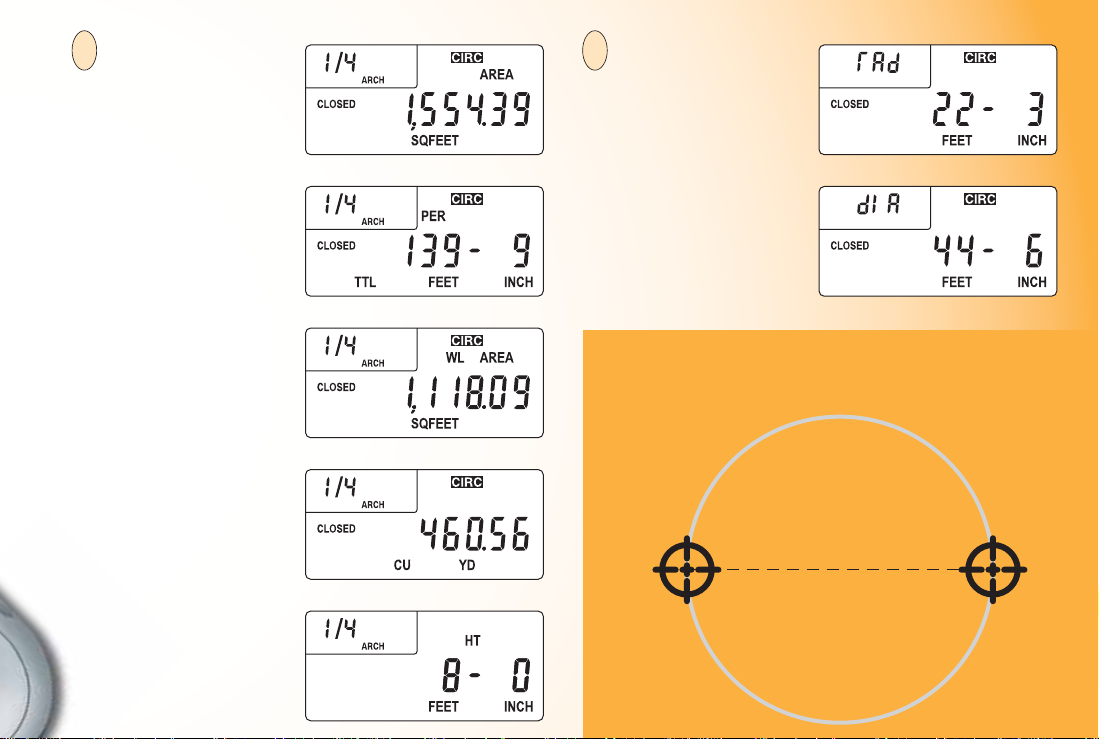
4. Upon pressing
4
the [MEASURE]
key in Step 3, the
Circle measurement
was automatically
completed and
the Circle Area
displayed. Once a
Circle measurement
is com pleted, press
the D-Pad down
[6] to display Circle
Perimeter, Circle Wall
Area, Circle Volume
and stored Height.
Continu ous presses
of the D-Pad down
[6] or up [5] will
scroll ba ck an d forth
through the values.
*Circle Wall Area, Circle
Volume and Height do
not display if a Height
has not been set. For
this example, a Height
of eight Feet was used.
(See Setting a Height
section for instructions
on setting a Height.)
CIRCLE AREA
CIRCLE PERIMETER
CIRCLE WALL AREA*
CIRCLE VOLUME*
HEIGHT*
5. Press the D-Pad
5
CIRCLE RADIUS
right [4] to display
the Circle Radius
and Circle Diameter.
Continuous presses
of D-Pad right [4]
will scroll through
CIRCLE DIAMETER
these values.
Repeated presses of
the D-Pad left [3] will
scroll back through
these values.
If you have an actual Diameter, follow steps 1 and 2
then replace step 3 with a press of the [CLOSE+] key.
Diameter
USER’S GUIDE — 35
Page 38

CUSTOM SCALES
There are two methods for programming Custom Scales
into your Ultra Scale Master Pro. “Measured Custom Scales”
allow you to measure a specifi ed Length and assign the
known value. “Entered Custom Scales” allow you to enter
and set a known scale that is not included within the
available built-in scales of the Ultra Scale Master Pro.
SETTING A MEASURED CUSTOM SCALE
Four Custom Scales can be stored in Imperial and Metric
Modes for a total of eight Custom Scales. Once a Custom
Scale has been set in either mode, it is retained until a new
scale is stored in its place or until an All Clear or Reset is
performed. Switching between Imperial and Metric Modes
does not clear stored Custom Scales.
1. Press [MODE] until “CUST” is displayed. Press [SCALE]
to scroll through the four available custom scales. For this
example, Custom Scale-1 is used.
2. Press [SET] then [SCALE] to begin setting the Custom
Scale. The display prompts you to enter Point-1.
36 — ULTRA SCALE MASTER
®
PRO
3. Place the crosshairs over the start point of the line and
press [MEASURE]. You are prompted to enter Point-2.
4. Place the crosshairs over the end point and press
[MEASURE]. The display shows “0,000-00” for Imperial
Mode and “00,000.0” is displayed for Metric Mode.
Page 39

5. The displayed units begin fl ashing, indicating that they
are ready to be changed. Press [UNITS] to scroll through
the available units.*
6. Press D-Pad right [4] to begin value entry mode. The
selected digit begins fl ashing, indicating that it is ready
to be changed. Use D-Pad right [4] and left [3] to move
between the digits.
8. To store the Custom Scale, press [SET] or [SCALE]. To
confi rm the scale has been set, “Scl Set” is displayed for
one second. Stored Custom Scales display “SET” instead
of “OPEN” (e.g., 1 SET).
*In Imperial Mode, only the following units are available:
Feet-Inch, Feet, and Inches.
In Metric Mode, only the following units are available: Meters,
Centimeters, and Millimeters.
7. Press D-Pad up [5] or down [6] to increase or decrease
the selected digit.
Note: This example is shown in
Imperial Mode. The displays will be
slightly different if in Metric Mode.
USER’S GUIDE — 37
Page 40

SETTING AN ENTERED CUSTOM SCALE (IMPERIAL MODE)
1. Press [MODE] until “CUST” is displayed. Press [SCALE]
to scroll through the four available Custom Scales. For
this example, Custom Scale-1 is used.
4. Use D-Pad right [4] to begin value entry mode. The
selected digit begins fl ashing, indicating that it is ready
to be changed. Use D-Pad right [4] and left [3] to move
between the digits.
2. Press [SET] then press [SCALE] [SCALE] to begin
entering the Custom Scale.
3. The displayed units begin fl ashing, indicating that they
are ready to be changed. Press [UNITS] to scroll through
the available units.*
38 — ULTRA SCALE MASTER
®
PRO
5. Use D-Pad up [5] or down [6] to increase or decrease the
selected digit.
6. To store the Custom Scale, press [SET] or [SCALE]. To
confi rm the scale has been set, “Scl Set” is displayed for
one second. Entered Custom Scales display the Inch-to-Feet
scale ratio instead of “OPEN” or “S ET” (e.g. 1 :15 for 1 Inch =
15 Feet).
*In Imperial Mode, only the following units are available: Feet-Inch, Feet and Inches
Page 41

SETTING A HEIGHT
A Height can be set to calculate Wall Areas and Volumes which are displayed using the D-Pad once an area measurement has
been completed. If no Height is stored, Wall Area and Vo lume are not displayed. The following example is shown in Imperial
Mode. The displays will be slightly different if in Metric Mode.
1. Press [SET] then [HEIGHT] to begin entering a Height.
2. The displayed units begin fl ashing, indicating that they
are ready to be changed. Press [UNITS] to scroll through
the available units.*
4. Use D-Pad up [5] or down [6] to increase or decrease the
selected digit.
5. T o store your Height, press [SET] or [HEIGHT]. T o confi rm
the Height has been set, “Ht Set” is displayed for one second.
3. Use D-Pad right [4] to begin value entry mode. The
selected digit begins fl ashing, indicating that it is ready
to be changed. Use D-Pad right [4] and left [3] to move
between the digits.
*In Imperial Mode, only the following units are available:
Feet-Inch, Feet and Inches.
In Metric Mode, only the following units are available: Meters,
Centimeters and Millimeters.
Note: Press [HEIGHT] to view a stored Height. A Height is only
cleared if a new Height is stored, an All Clear or Reset is performed,
or if the unit is switched between Imperial and Metric Modes.
USER’S GUIDE — 39
Page 42

UNITS OF MEASUREMENT
The following units of measurement are available for selection by pressing the [UNITS] key located under the slide cover
door. You may change the units of measurement of a displayed value at anytime during measuring, or after a measurement
has been completed. All of the Linear, Area, and Volume units shown below are available in both Imperial and Metric modes
and are displayed in the order shown beginning with the default. The Imperial/Metric switch (located on the back of the Puck)
determines the default starting unit:
LINEAR UNITS
Feet-Inch (FEET INCH)*
Feet (FEET)
Yards (YD)
Meters (M)**
Centimeters (CM)
Millimeters (MM)
Inch (INCH)
*Imperial Default
**Metric Default
Note: You may change units on any displayed value, even while measuring. Continuous presses of [UNITS] will scroll through the available
units of measurement listed above, converting the displayed value. If the value is too large to be displayed in the units selected, the display
will remain unchanged (maintaining the same value and units) until the value is converted to a unit that can be displayed.
40 — ULTRA SCALE MASTER
®
PRO
AREA UNITS
Square Feet (SQ FEET)*
Square Yards (SQ YD)
Acres (AC)
Square Meters (SQ M)**
Square Centimeters (SQ CM)
Square Millimeters (SQ MM)
Hect ares (HA)
Square Inches (SQ INCH)
Note: If a measurement or calculation with small units of measurement
exceeds the seven-digit range of the display, it will be automatically
displayed in the next larger units (e.g. 20,000,000 millimeters is
displayed as 20,000.00 m).
VOLUME UNITS
Cubic Yards (CU YD)*
Cubic Feet (CU FEET)
Cubic Meters (CU M)**
Cubic Centimeters (CU CM)
Cubic Millimeters (CU MM)
Cubic Inches (CU INCH)
Page 43

DIGITIZER MODE
The Ultra Scale Master Pro can be used as a Digitizer to send measurement data (X,Y coordinates) and key press data to digitizing
software on a host personal computer (PC). See PC Interface section for system requirements and USB connection information.
Press the [DIGITIZER] key to enter Digitizer Mode. Display will show “digi On.” It will remain in Digitizer Mode until the
[DIGITIZER] key is pressed again, or when a manual reset is performed (see Reset section).
WHILE IN DIGITIZER MODE:
The following keys send measurement data (X,Y coordinates) and key press data:
[MEASURE]
[END]
[CLOSE –]
[CLOSE +]
The following keys send only the key press data:
[UNDO] D-Pad Up [5] [PC SEND] [MOD E ] [HEIGHT]
D-Pad Down [6] [ARC/CIRC] [SCALE] [PREFS]
[M+] D-Pad Right [4] [MR] [UNITS]
D-Pad Left [3]
The following keys send no data:
[ON/CLEAR]
[SET]
[DIGITIZER]
USER’S GUIDE — 41
Page 44

PC INTERFACE
The Ultra Scale Master Pro with PC Interface can be used to send displayed
numerical values from your Puck directly to the selected estimating, spreadsheet,
word processing, or text editing program on your PC. It can also be used to send
data to digitizing programs while in Digitizer Mode (see Digitizer Mode sectio n).
The PC Interface is a ten-foot long
USB cable specially designed for
use with the Ultra Scale Master Pro.
There is no driver software needed.
Simply follow the instructions
below to connect your
Ultra Scale Master Pro to your PC.
1. Insert the small end of the USB
cable into the USB plu g located on the
bottom end of the Puck.
SYSTEM REQUIREMENTS:
— Windows 2000, XP, Vista Operating Systems — One USB port
Note: When connected to a PC, a small PC-shaped icon will appear at the upper right side of the Puck’s display , indicati n g a valid connection has
been established. This icon will be displayed only when the USB cable is securely connected to the Puck and the PC. The USB cable is specially
designed for use only with the Ultra Scale Master Pro. The Ultra Scale Master Pro cannot be used with any other USB cable.
42 — ULTRA SCALE MASTER
®
PRO
2. Insert the large
end of the USB
cable into the USB
port on the PC.
Page 45

SENDING VALUES TO YOUR PC (PC SEND)
The [PC Send] key sends the displayed value from the Puck to the selected software program on your PC. Values can be sent to the
PC during a measurement and after it has been completed.
Only numeric values can be sent to the PC. Preference settings and error messages cannot be sent to the PC. Also, the following
measurement prompts cannot be sent to the PC:
Start.Pt Point 2 Ent Pt.1
High Pt Point 3 Ent Pt.2
Final.Pt
Note: Values cannot be sent to the PC while setting a Custom Scale or setting a Height.
There are three Preferences that determine how values are sent to the PC (see Preferences section for information on accessing and
changing the Preferences).
PC SEND TERMINATING COMMAND:
Enter* - Performs an ENTER command after
value is sent to the PC.
Tab - Performs a TAB command after value
is sent to the PC.
Left - Performs a LEFT command after value
is sent to the PC.
Right - Performs a RIGHT command after
value is sent to the PC.
Up - Performs an UP command after value
is sent to the PC.
Dn - Performs a DOWN command after
value is sent to the PC.
None - Performs no action after value is sent
to the PC.
PC SEND DISPLAY:
Hold* - The displayed value is not cleared
after being sent to the PC.
Clr - The displayed value is Cleared after
being sent to the PC. This setting is
ignored while measuring.
USB SEND DELAY:
Delay 1* - FASTEST USB send speed.
Delay 2 - MEDIUM USB send speed.
Delay 3 - SLOW USB send speed.
Delay 4 - SLOWEST USB send speed.
Use this setting to reduce the USB send speed if
using a slower computer and experiencing problems
sending values.
*An asterisk denotes a default value.
USER’S GUIDE — 43
Page 46

The following is an example of the
results of a Polygon measurement,
which include the Area, Perimeter,
Wall Area, and Volume.
In the fi rst column are the values as
they would appear on the display of
your Puck.
In the second column are the values
as they would appear after being
sent to a spreadsheet program on
the PC. The data will appear within
the selected area of the software
program on the PC (in this case the
cells of the spreadsheet).
The Ultra Scale Master Pro displays
“SEnt PC” for one second each time a
value is sent to the PC successfully.
Note: The decimal equivalent of the value
in the main display of the Puck is sent to
the PC each time [PC Send] is pressed.
DISPLAYED RESULTS RESULTS DISPLAYED IN SPREADSHEET
AREA
PERIMETER
WALL AREA
VOLUME
1
2
Area
3
Perimeter
4
Wall Area
5
Volume
6
1
2
Area
3
Perimeter
4
Wall Area
5
Volume
6
1
2
Area
3
Perimeter
4
Wall Area
5
Volume
6
1
2
Area
3
Perimeter
4
Wall Area
5
Volume
6
A
A
A
A
B
Room 1 Room 2 Room 3
281.55
B
Room 1 Room 2 Room 3
281.55
67.50
B
Room 1 Room 2 Room 3
281.55
67.00
63.96
B
Room 1 Room 2 Room 3
281.55
67.00
63.96
17.67
C D
C D
C D
C D
44 — ULTRA SCALE MASTER
®
PRO
Page 47

PREFERENCES
The following Preferences allow you to customize your Ultra Scale Master Pro. Access the Preferences by pressing [PREFS],
located under the slide cover door. Press D-Pad up [5] or down [6] to scroll through the Preferences. Press D-Pad right [4] or
left [3] to scroll through the available settings within the selected Preference.
1. MEASUREMENT DISPLAY:
Total* – Displays the accumulated total of all measured segments.
Side – Displays only the last measured segment.
2. BEEP:
On* – Beeps once after:
• a successful measurement
• a successful PC data send
– Beeps twice after:
• an unsuccessful measurement
• an unsuccessful PC data send
• an error
Error – Beeps twice only after:
• an unsuccessful measurement
• an unsuccessful PC data send
• an error
Off – Beep is turned off (never beeps)
3. US/EURO DISPLAY:
US* – Displays commas and decimals in standard US format;
commas separate groups of three digits and decimals
separate whole digits from decimal digits (e.g., 1,234.00).
Euro – Displays commas and de cimals in sta nd ard Europea n
format; comma s separate whole digits from fractional
digits a nd decimals separate groups of t hree digits
(e.g ., 1.234,00).
4. PC SEND DISPLAY:
Hold* – The displayed value is not cleared after being sent to the
PC.
Clr – The displayed value is cleared after being sent to the PC.
This setting is ignored while measuring.
USER’S GUIDE — 45
Page 48

5. PC SEND TERMINATING COMMAND:
Enter* – Performs an ENTER command after value is sent to the PC.
Tab – Performs a TAB command after value is sent to the PC.
Left – Performs a LEFT command after value is sent to the PC.
Right – Performs a RIGHT command after value is sent to the PC.
Up – Performs an UP command after value is sent to the PC.
Dn – Performs a DOWN command after value is sent to the PC.
None – Performs no action after value is sent o the PC.
6. DIGITIZER OPERATION ORIENTATION:
Right* – Sets to right-hand operation orientation while in
Digitizer Mode. See Right-Hand Assembly section.
Left – Sets to left-hand operation orientation while in Digitizer
Mode. See Left-Hand Assembly section.
7. USB SEND DELAY:
Delay 1* – FASTEST USB send speed.
Delay 2 – MEDIUM USB send speed.
Delay 3 – SLOW USB send speed.
Delay 4 – SLOWEST USB send speed.
Use this setting to reduce the USB send speed if using a slower
computer and experiencing problems sending values.
*An asterisk denotes a default value.
46 — ULTRA SCALE MASTER
®
PRO
Page 49

APPENDIX A APPENDIX B
ACCURACY/ERRORS/AUTO SHUT-OFF
Accuracy/Display Capacity – The Ultra Scale Master Pro
has a seven-digit main display, while maintaining an
internal accuracy of 12-digits for calculations. The
Ultra Scale Master Pro is capable of measuring at an accuracy
of +/– 0.040" within a measuring range between one-inch and
36-inches from the refl ector bars.
Errors – The following is a list of the error messages that will
display after errors such as incorrect measurements or key presses
are made. T wo beeps will also sound after an error occurs if the
Beep Preference setting is set to “On” (default) or “Error.”
REAd Error – Unable to take measurement, bad
measurement, out of range or too close to bars
Error – Scale setting error (such as storing zero into a
Custom Scale), math or dimension error (usually occurs
when attempting to store values of different dimensions
into Memory)
OFLO – Overfl ow (value is too large to be displayed)
SEnd Error – Not connected to a PC
Auto Shut-off – The Ultra Scale Master Pro is designed to shut
itself off after 8-12 minutes of non-use. All of the current settings
and measurements are saved automatically.
RESET
All Clear – All values can be cleared and all settings except
Preferences returned to their defaults by pressing:
[SET] [END] [END]
“ALL CLEArEd” will display for one second indicating that
an All Clear has been performed.
Manual Reset – All values can be cleared and all settings
including the Preferences returned to their defaults by
performing a manual reset. A manual reset can be performed
by using a paperclip (or something of similar size) to press
into the small reset hole located beneath the bottom slide
cover. “ALL rESEt” will display for one second indicating
that the device has been reset.
See Setup Keys section for the location of the reset hole.
USER’S GUIDE — 47
Page 50

APPENDIX C APPENDIX D
Operating Modes Stand Alone Operation, PC Input Mode,
Digitizer Tablet Coordinate Entry (optional
software is required)
Operating Systems Supported Windows 2000, XP & Vista
Computer Interface USB 1.1 and 2.0 compatibile HID Mode
Bar Dimensions:
Footprint 651 x 956 x 36 mm (25.63 x 37.63 x 1.40 inch)
Active Measurement Area 610 x 914 mm (24 x 36 inch) (re-configurable)
Weight 1049 grams (2.31 lbs)
Puck Dimensions:
Footprint 294 x 199 x 30 mm (11.57 x 7.83 x 1.18 inch)
Weight 200 grams (7 oz)
Power Source USB power when connected to PC
4 "AAA" batteries when used as stand alone
Range 1 to 36 inches
Accuracy ±0.040 inch
Operating Temperature 5 to 40°C (41 to 104°F)
Storage Temperature -20 to 60°C (14 to 122°F)
Humidity Range 0 to 95%, non-condensing
SPECIFICATIONS REPAIR AND RETURN
WARRANTY, REPAIR AND RETURN INFORMATION
Return Guidelines
48 — ULTRA SCALE MASTER
®
PRO
1. Please read the Warranty in t his User’s Guide to
determine if your Calculated Industries product
remai ns under warranty before calli ng or r eturning any
device for evaluation or repairs.
2. If your product won’t tu rn on, check the battery as
outlined i n the User’s Guide.
3. If you need more assista nce, please go to the website
listed below.
4. If you believe you need to return your product, please call a
Calculated Industries representative between the hours of
8:00am an d 4:00pm P a cifi c Time for additional information
and a Return Merchandise Authorization (RMA).
Call Toll Free: 1-800-854-8075
Outside USA: 1-775-885-4900
www.calculated.com/war ranty
WARRANTY
Warranty Repair Service – U.S.A.
Calculated Industries (“CI”) warrants this product against
defects in materials and workmanship for a period of one (1)
year from the date of original consumer purchase in the U.S.
Page 51

If a defect exists during the warranty period, CI, at its option,
will either repair (using new or remanufactured parts) or
replace (with a new or remanufactured digitizer) the product
at no charge.
THE WARRANTY WILL NOT APPLY TO THE PRODUCT
IF IT HAS BEEN DAMAGED BY MISUSE, ALTERATION,
ACCIDENT, IMPROPER HANDLING OR OPERATION,
OR IF UNAUTHORIZED REPAIRS ARE ATTEMPTED OR
MADE. SOME EXAMPLES OF DAMAGES NOT COVERED
BY WARRANTY INCLUDE, BUT ARE NOT LIMITED TO,
BATTERY LEAKAGE, BENDING, A “BLACK INK SPOT”
OR VISIBLE CRACKING OF THE LCD, WHICH ARE
PRESUMED TO BE DAMAGES RESULTING FROM MISUSE
OR ABUSE.
To obtain warranty service in the U.S., please go to the
website. A repaired or replacement product assumes the
remaining warranty of the original product or 90 days,
whichever is longer.
Non-Warranty Repair Service – U.S.A.
Non-warranty repair covers service beyond the warranty
period, or service requested due to damage resulting from
misuse or abuse.
Contact Calculated Industries at the number listed above
to obtain current product repair information and charges.
Repairs are guaranteed for 90 days.
Repair Service – Outside the U.S.A.
To obtain warranty or non-warranty repair service for goods
purchased outside the U.S., contact the dealer through which
you initially purchased the product. If you cannot reasonably
have the product repaired in your area, you may contact CI
to obtain current product repair information and charges,
including freight and duties.
Disclaimer
CI MAKES NO WARRANTY OR REPRESENTATION, EITHER EXPRESS OR IMPLIED,
WITH RESPECT TO THE PRODUCT’S QUALITY, PERFORMANCE, MERCHANTABILITY,
OR FITNESS FOR A PARTICULAR PURPOSE. AS A RESULT, THIS PRODUCT,
INCLUDING BUT NOT LIMITED TO, KEYSTROKE PROCEDURES, MATHEMATICAL
ACCURACY AND PREPROGRAMMED MATERIAL, IS SOLD “AS IS,” AND YOU THE
PURCHASER ASSUME THE ENTIRE RISK AS TO ITS QUALITY AND PERFORMANCE.
IN NO EVENT WILL CI BE LIABLE FOR DIRECT, INDIRECT, SPECIAL, INCIDENTAL,
OR CONSEQUENTIAL DAMAGES RESULTING FROM ANY DEFECT IN THE PRODUCT
OR ITS DOCUMENTATION.
The warranty, disclaimer, and remedies set forth above are exclusive and replace all others,
oral or written, expressed or implied. No CI dealer, agent, or employee is authorized to
make any modifi cation, extension, or addition to this warranty. Some states do not allow
the exclusion or limitation of implied warranties or liability for incidental or consequential
damages, so the above limitation or exclusion may not apply to you. This warranty gives
you specifi c rights, and you may also have other rights, which vary from state to state.
FCC Class B
This equipment has been certifi ed to comply with the limits for a Class B computing
device, pursuant to Subpart J of Part 15 of FCC rules.
Looking for New Ideas
Calculated Industries, a leading manufacturer of special-function calculators and digital
measuring instruments, is always looking for new product ideas in these areas. If you have
an idea, or a suggestion for improving this product or User’s Guide, please submit your
comments online at www.calculated.com under “Contact Us”, “Product Idea Submittal
Agreement.” Thank you.
USER’S GUIDE — 49
Page 52

Software copyrighted and licensed to
Calculated Industries, Inc. by
Scale Master Technologies, LLC, 2007.
User’s Guide copyrighted by
Calculated Industries, Inc. © 2007.
Ultra Scale Master® Pro and Calculated Industries® are
registered trademarks of Calculated Industries, Inc.
ALL RIGHTS RESERVED CALCULATED INDUSTRIES®
4840 Hytech Drive
Carson City, NV 89706 U.S.A.
1-800-854-8075, 1-775-885-4900, Fax: 1-775-885-4949
www.calculated.com
Designed in the U.S.A.
Printed in China
01/ 07
UG6260E—A
 Loading...