

Page 1
USER’S
GUIDE
Digital AreaTake-Off Tool
Model
#6250
Page 2
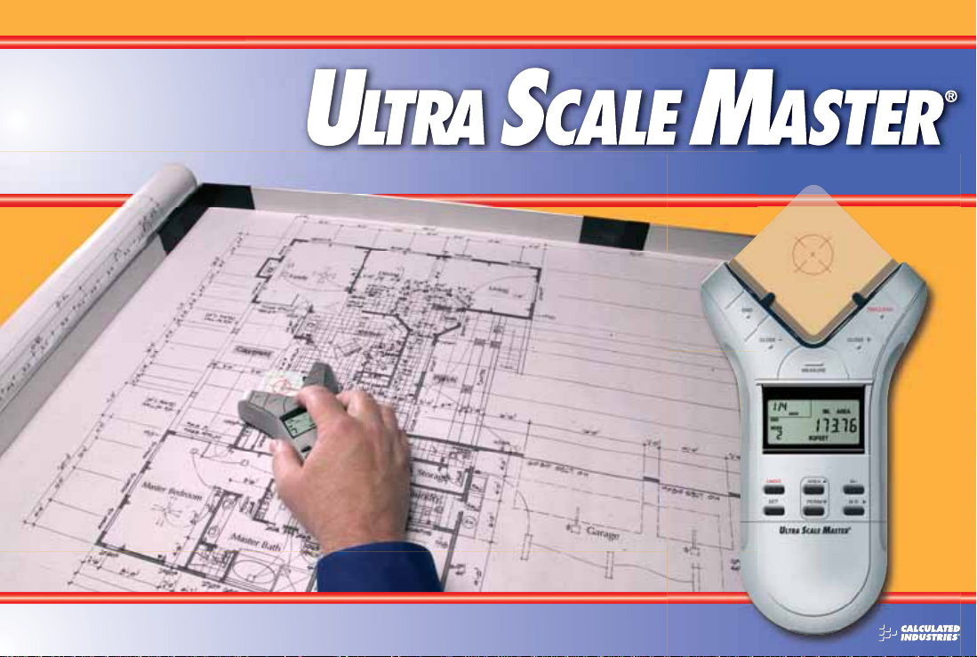
INTRODU CTION
The Ultra Scale Master
has been specifi cally
designed to simplify
take-offs for all fi elds
of construction. Use it
for estimating project
materials and costs, for
measuring, storing and
calculating perimeters,
areas, and volumes from
architectural plans and
other types of scaled
drawings. Also , use the
Ultra Scale Master to
calculate the area of
irregular shapes.
Page 3
Page 4

TABLE OF CONTENTS
SETUP . . . . . . . . . . . . . . . . . . . . . . . . . . . . . . . . . . . . . . . . . . . . . . . .2
PACKAGE CONTENTS . . . . . . . . . . . . . . . . . . . . . . . . . . . . . . . . . . .2
RIGHT-HAND ASSEMBLY . . . . . . . . . . . . . . . . . . . . . . . . . . . . . . .4
LEFT-HAND ASSEMBLY . . . . . . . . . . . . . . . . . . . . . . . . . . . . . . . . .6
GETTING STARTED . . . . . . . . . . . . . . . . . . . . . . . . . . . . . . . . . . . . .8
KEY DEFINITIONS . . . . . . . . . . . . . . . . . . . . . . . . . . . . . . . . . . .10
MEASURING KEYS . . . . . . . . . . . . . . . . . . . . . . . . . . . . . . . . . . . .10
FUNCTION KEYS . . . . . . . . . . . . . . . . . . . . . . . . . . . . . . . . . . . . . 12
SETUP KEYS . . . . . . . . . . . . . . . . . . . . . . . . . . . . . . . . . . . . . . . . . 14
USING THE ULTRA SCALE MASTER . . . . . . . . . . . . . . . . . . . 16
UNDERSTANDING THE LCD . . . . . . . . . . . . . . . . . . . . . . . . . . . . . 16
BUILT-IN SCALES . . . . . . . . . . . . . . . . . . . . . . . . . . . . . . . . . . . . .17
SHAPES AND DEFINITIONS . . . . . . . . . . . . . . . . . . . . . . . . . . . . .18
MEASURING POLYLINES . . . . . . . . . . . . . . . . . . . . . . . . . . . . . . .19
MEASURING SIMPLE POLYGONS . . . . . . . . . . . . . . . . . . . . . . . .20
MEASURING TAKE-OUTS . . . . . . . . . . . . . . . . . . . . . . . . . . . . . . 21
MEASURING COMPLEX POLYGONS . . . . . . . . . . . . . . . . . . . . . .23
MEASURING IRREGULAR SHAPES . . . . . . . . . . . . . . . . . . . . . . .24
CUSTOM SCALES . . . . . . . . . . . . . . . . . . . . . . . . . . . . . . . . . . . .25
SETTING A MEASURED CUSTOM SCALE . . . . . . . . . . . . . . . . . . .25
SETTING AN ENTERED CUSTOM SCALE (IMPERIAL MODE) . . . . .27
UNITS OF MEASUREMENT . . . . . . . . . . . . . . . . . . . . . . . . . . . . .28
APPENDIX A . . . . . . . . . . . . . . . . . . . . . . . . . . . . . . . . . . . . . . . . 29
ACCURACY/ERRORS/AUTO SHUT-OFF. . . . . . . . . . . . . . . . . . . . .29
APPENDIX B . . . . . . . . . . . . . . . . . . . . . . . . . . . . . . . . . . . . . . . .29
RESET . . . . . . . . . . . . . . . . . . . . . . . . . . . . . . . . . . . . . . . . . . . . . 29
APPENDIX C . . . . . . . . . . . . . . . . . . . . . . . . . . . . . . . . . . . . . . . .30
SPECIFICATIONS . . . . . . . . . . . . . . . . . . . . . . . . . . . . . . . . . . . . .30
APPENDIX D . . . . . . . . . . . . . . . . . . . . . . . . . . . . . . . . . . . . . . . .30
REPAIR AND RETURN . . . . . . . . . . . . . . . . . . . . . . . . . . . . . . . . .30
USER’S GUIDE — 1
Page 5
SETUP
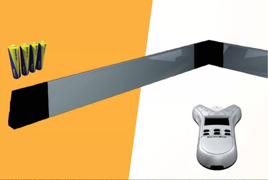
PACKAGE CONTENTS
Your package contains the following pieces:
Four “AAA ” batteries
(already installed)
Female End Cap
Corner Connector
Long Refl ector Bar
Ultra Scale Master Pro
model 6250 (Puck)
2 — ULTRA SCALE MASTER
®
Page 6
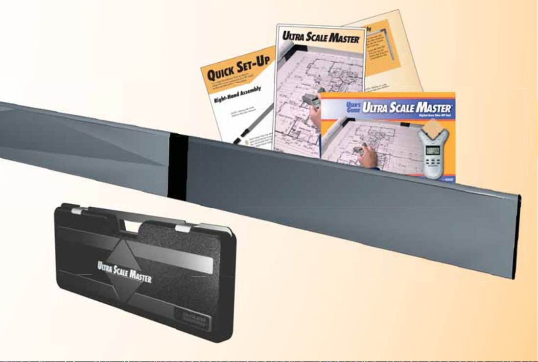
Long Refl ector Bar
Carrying Case
User’s Guide,
Quick Reference Guide,
and Quick Setup Sheet
Short Refl ector Bar
Male End Cap
USER’S GUIDE — 3
Page 7
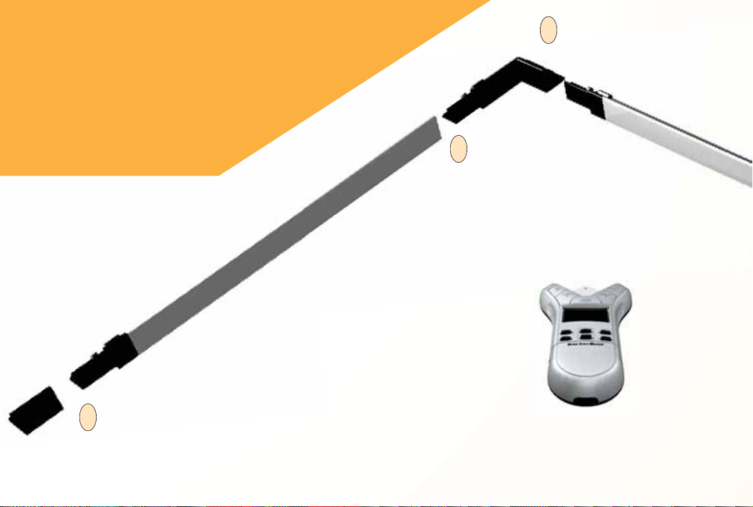
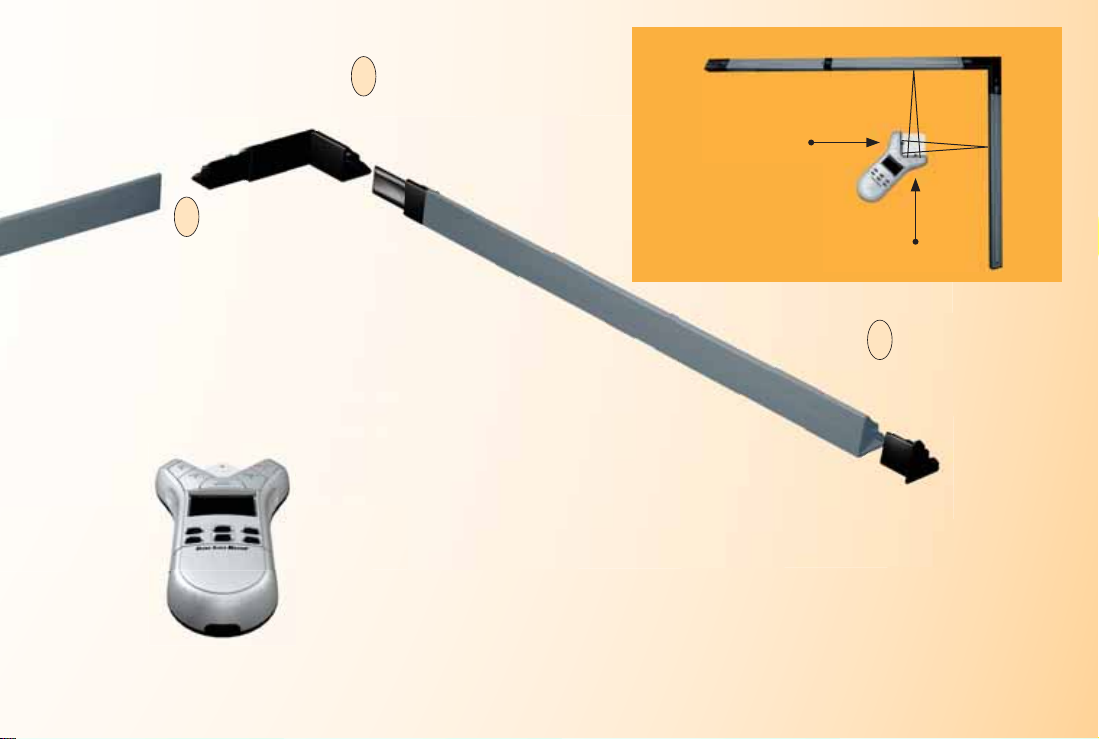
RIGHT-HAND ASSEMBLY
Assemble the refl ector bars
as shown. Align the corner
connector at a 90° angle at the
top left corner of the plans.
NOTE: Sloping side of the Refl ector
Bars face outward.
5. Slide Female End Cap onto the male end of the fi rst Long Refl ector Bar.
5
The Female End Cap is preinstalled for a Right-Hand confi guration.
2. Insert the male end of the second
2
Long Refl ector Bar into the female
end of the Corner Connector.
1. Insert the male end of the
1
Corner Connector into
the female end of the fi rst
Long Refl ector Bar.
4 — ULTRA SCALE MASTER
®
Page 8
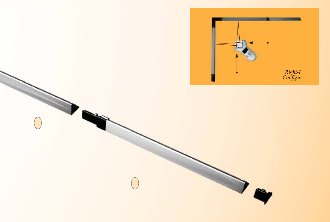
2nd Long Refl ecto r Bar Short Refl ector Bar
Right
Puck Arm
NOTE: Sloping side of the Refl ector
Bars face outward.
3. Insert the male
3
end of the Short
Refl ector Bar into
the female end of
the second Long
Refl ector Bar.
FINAL ASSEMBLY
The ultrasonic beams are sent from the left arm of
the Puck to the top bar, then refl ected back, and
from the right arm of the Puck to the side bar, then
refl ected back as shown above.
The Puck can be moved to any point within the bars
as long as the left arm remains parallel to the top bar
and the right arm remains parallel to the side bar as
shown above.
4. Insert the Male End Cap into
4
the female end of the Short
Refl ector Bar. The Male End
Cap is preinstalled for a RightHand confi guration.
1st Long Refl ector Bar
Left
Puck Arm
Right-Hand
Confi guration
USER’S GUIDE — 5
Page 9
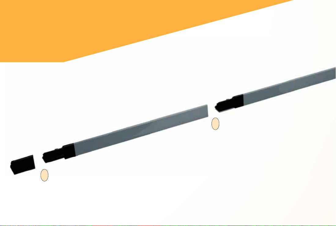
LEFT-HAND ASSEMBLY
Assemble the refl ector bars as shown. Align
the corner connector at a 90° angle at the
top right corner of the plans.
4. Insert the male end of the Short Refl ector
4
Bar into the Female Bar End Cap.
NOTE: Sloping side of the Refl ector
Bars face outward.
5. Insert the the male end of
3
the second Long Refl ector
Bar into the female end of
the Short Refl ector Bar.
6 — ULTRA SCALE MASTER
®
Page 10
1. Insert male end
2
of the Corner
Connector into
the female end of
the second Long
Refl ector Bar.
1. Insert the male end of the
1
fi rst Long Refl ector Bar
into the female end of the
Corner Connector.
2nd Long Refl ector BarShort Refl ector Bar
1st Long Refl ector Bar
Left
Puck Arm
Left-Hand
Confi guration
Right
Puck Arm
4. Insert the Male Bar
5
End Cap into the
female end of the fi rst
Long Refl ector Bar.
FINAL ASSEMBLY
The ultrasonic beams are sent from the right arm of
the Puck to the top bar, then refl ected back, and from
the left arm of the Puck to the side bar, then refl ected
back as shown above.
The Puck can be moved to any point within the bars
as long as the right arm remains parallel to the top
bar and the left arm remains parallel to the side bar
as shown above.
USER’S GUIDE — 7
Page 11

GETTING STARTED
Once assem bly and se tup are complete, proceed with the following ste ps in
order to begin measuring.
1. When placing the bar s and securi ng the drawing, make sur e that the
bars are at least 1" from the outermost me a surements.
2. It is essential that the bars rema in fi xed r el at ive to the drawing’s
position. Scrib e a line to mark the initial location of the bars a s a
reference point should t he bars shift.
3. The Puck should maintain a 45° angle with in the bars while me a suring.
4. Ensure that the measuring surface is fl at and smooth. Make sure there
are no folds, tears, or raise d areas of the plans.
5. Make sure there ar e no ob jects between the Puc k and the bars. Thi s
includes hands, arms, pencils or pens, cups, scale rulers, etc.
6. Make sure th at no air current is blowing d irectly into the measuring
area. Air blowi ng into the measuri ng path c an result in no
measureme nt re ad ing.
7. To get accurate measurements, make sur e that the Puck and the ba r s are
close to the a mbient temperat ure of the work environment.
8 — ULTRA SCALE MASTER
®
Page 12

Right-Hand Confi guration Shown
USER’S GUIDE — 9
Page 13

KEY DEFINITIONS
MEASURING KEYS
The keys shown are u s ed
for taking measurements on
the blueprint and operat ing
the display.
[END]
Ends polyli ne measurement,
displaying t he tot al perimeter.
[CLOSE —]
Completes the polygon and
displays the calculated area.
Results are identifi ed as negative
values. When measuring a
polygon, this key connects the last
measured point to the start point.
10 — ULTRA SCALE MASTER
®
Page 14

[ON/CLEAR]
Turns the unit ON and clears
the display. Holding down t he
[ON/CLEAR] key for 1.5 seconds
also powers the unit off.
[CLOSE +]
Completes the polygon
and displays the calcu lated
area. Results ar e identi fie d
as positive values. When
measuri ng a polygon, thi s key
connect s t he last me asu re d
point to the sta rt poi nt.
[MEASURE]
Takes a measurement
between points.
Important Notes
regarding the
[ON/ CLE AR] key:
If [ON/CLEAR] is pressed
dur ing measurement,
the last meas ured point
is undone and t he
previous measur e me nt i s
displayed. A second press
of [ON/CLEAR] ends the
measurement (as if the
[END] key was pre s s e d)
and clears the main display .
Additionally, if a n error
message is displayed
during a mea surement,
pressing [ON/CLEAR]
clears the error message
and displays the previous
measure ment.
USER’S GUIDE — 11
Page 15

FUNCTION KEYS
FUNCTION KEYS
[UNDO]
Undoes the previous mea sure ment.
Allows you to undo the last ten
measurement s (if applicable) while in
measure mode. If a mea sur ement ha s
been close d or ended, it wil l u ndo the
close or end act ion and t he previous
nine mea sur ements upon re peated
press es of [UNDO].
[SET]
Used in conjunc t ion w it h the [SCALE]
key to set a custom s ca le (see Custom
Scales sect ion). Also used to acce ss
secondary functions (e.g., M-, MC).
[AREA]
Displays the calcu lated a re a of t he
measure d points.
UP ARR OW
5
Used to change the units of measurement
and increase the selected digit while setting
a custom scale (See Custom Scales section).
12 — ULTRA SCALE MASTER
®
Page 16

[M+]
Adds the displayed value to
accumulative memory (except when
setting a Custom Scale).
[SET] [M+] (M—)
Subtracts the displayed value fr om
the accumul at ive memory (except
during a mea surement).
[MR] (Memory Recall)
First press displays the accumulative
memory value; second consecut ive press
displays memory count; third consecutive
press displays the memory average.
Repeated presses cycle back through the
list of values.
RIGHT ARROW
4
Used to move through the digits
while setting a custom scale (see Custom
Scales setting).
[SET] [MR] (Memor y Clear)
Clears the acc umulative memory.
[PERIM]
Displays the calcu lated pe rimeter
(accumulated length) of the
measure d points.
DOWN ARROW
6
Used to change the units of measurement
and decrease the selected digit while setting
a custom scale (see Custom Scales setting).
USER’S GUIDE — 13
Page 17

SETUP KEYS
The buttons shown below
are accessed by sliding the
bottom cover down until
they are revealed.
[MODE]
Used to select from the list of
available modes (see Built-In
Scales section).
[SET] [MODE]
Used to move back through the
list of available modes.
[SCALE]
Used to select from the list of
available scales within each
mode (see Built-in Scale s section).
[SET] [SCALE]
Used to move back through the
list of available sca les.
[RESET]
Clears all values and resets all
setting s inclu d ing pre f erence s
to their factory defa ults. (Use the
end of a paperclip or something of
similar size to press.)
14 — ULTRA SCALE MASTER
®
Page 18

[UNITS]
Used to select from the list of
available units of mea surement
(see Units of Measurement section).
[SE T] [ UNITS]
Used to move back through
the list of avail able u nits of
measure ment.
USER’S GUIDE — 15
Page 19

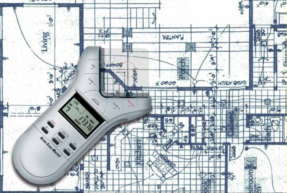
USING THE ULTRA SCALE MASTER
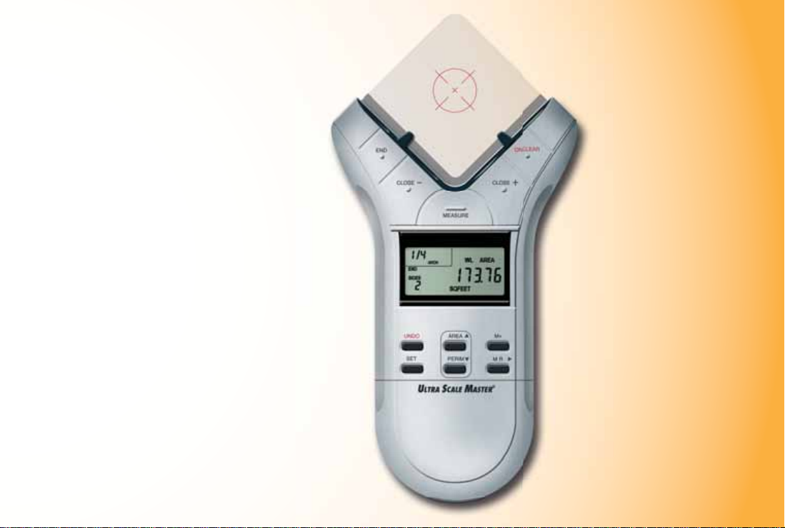
UNDERSTANDING THE LCD
The selected Scale and Scale
Category or “Mode” are displayed
here. The Modes are as identifi ed:
• ARCH (Architectural)
• ENG I/ENG II (Engineering)
• CUST (Custom)
The Measure Status
and number of sides
are displayed here
(End or Closed are
displayed only when
a measurement has
been completed).
16 — ULTRA SCALE MASTER
®
The Top Legend displays
the following:
• SET
• M (Memory)
Low Battery Indicator
The area immediately
below the Legend displays
the following:
• PER (Perimeter)
• AREA
Unit Legend is a
descriptions of
displayed values
(i.e. Square Feet, Inch).
This area,
often referred
to as the “Main
Display,” is
used to display
values and
important
messages.
Page 20

BUILT-IN SCALES
The following modes and scales
are available for selection using
the [MODE] and [SCALE] keys,
depending on whether the puck
is set to Imperial or Metric mode
using the [IMP/MET] switch
located on the back of the puck.
While in Imperial Mode, only the
Imperial Modes and Scales are
displayed. While in Metric Mode,
only Metric Modes and Scales are
displayed. However, all Imperial
and Metric units of measurement
are available within both modes.
When switching back and forth
between Imperial and Metric
modes, your settings within
each mode are held, including
Preference. The values stored in
[M+] are cleared when switching
between Imperial and
Metric modes.
Note: W hile in Metr ic Mode, MET
will appear in the scale area of
the display to indicate that it is in
Metric Mode.
IMPERIAL
Modes Scales
Architectural (ARCH)
1 Foot =
Engineering I (ENGI)
1 Inch =
Engineering II (ENGII)
1 Inch =
1/4," 3/8," 1/2," 3/4," 1/1" (1"), 3/2" (1-1/2"), 2/1" (2"),
3/1" (3"), 4/1" (4"), 1/32," 1/16," 3/32," 1/8," 3/16"
10. 0,' 20.0,' 30.0,' 4 0.0,' 50.0,' 60.0,' 83.3,' 100.0,' 166.6,'
200.0,' 250.0'
300.0,' 333.3,' 400.0,' 416.6,' 500.0,' 583.3,' 600.0,' 625.0,'
666.6,' 750.0,' 1,000,' 1,200,' 2,000,' 3,000'
METRIC
Modes Scales
Architectural
(MET ARCH)
Engineering I
(MET ENGI)
Engineering II
(MET ENGII)
1:50, 1:75, 1:1, 1:2, 1:3, 1:4, 1:5, 1:10, 1:20, 1:25, 1:30, 1:40
1:100, 1:125, 1:150, 1:200, 1:250, 1:300, 1:400, 1:500
1:1000, 1:1250, 1:1500, 1:1625, 1:2000, 1:2500, 1:5000,
1:6000, 1:10k, 1:12.5k, 1:20k, 1:25k, 1:50k
Note: Th e de fault Modes and Sc ales are listed fi rst and the remaining Modes and Scales
are listed in the order that they appear on your Ultra Scale Master.
USER’S GUIDE — 17
Page 21

SHAPES AND DEFINITIONS
The Ultra Scale Master can measure Polylines, Polygons, and regular or irregular shapes, based on the following criteria:
• Only one shape can be measured at a time • A measured Area cannot contain lines that cross each other
Defi nitions and illustrations of some common shapes: Solution examples follow in the User’s Guide:
POLYLINE:
A sequence of connected straight lines or a single
linear distance like a fence line
IRREGULAR SHAPE: An outline or
surface confi guration of a form
POLYGON: A closed geometric fi gure bounded by three or more straight lines
1. Simple Polygon:
A Square, Rectangle or Triangle
Note: Th e diag rams show n throughout the guide are not to scale and the displayed values are not representative of diagrams.
18 — ULTRA SCALE MASTER
®
2. Complex P o l y g on:
A multi-sided shape that is not a Square,
Rectangle or Triangle
Page 22

ILLEGAL SHAPE:
The Area can not be calculated for a
shape containing bisecting lines. The
Area of the shapes resulting from
the bisecting line s c an be calculated
individually.
MEASURING POLYLINES
OPERATING SEQUENCE
1. Press the [ON/CLEAR] key twice to clear the display.
1
Place the crosshairs over the fi rst point and press the
[MEASURE] key.
2. Move to the second point and press the [MEASURE] key.
2
The display will show the Length of the 1st line segment.
3. Move to the third point and pre ss t he [MEASURE]
3
key. The d isplay wil l show the accu mulated Leng t h
of the two measu red seg ment s.
2
PERIMETER
3 4
1
4. Press the [END] key. The
4
total Perimeter is displayed.
USER’S GUIDE — 19
Page 23

MEASURING SIMPLE POLYGONS
OPERATING SEQUENCE
1. Press the [ON/CLEAR] key twice to clear the display.
1
Place the crosshairs over the fi rst point and press the
[MEASURE] key.
2. Move to the second point and press the [MEASURE] key.
2
The display will show the Length of the fi rst line segment.
3. Move to the third point and pre ss t he [MEASURE]
3
key. The d isplay wil l show the accu mulated Leng t h
of the two measu red seg ment s.
4. Move to the fourth point and press the [MEASURE] key.
4
The display wil l show the accu mulated Leng t h of the
thre e measu red s eg ments.
2
1
20 — ULTRA SCALE MASTER
3
AREA
5. Press the [CLOSE+]
5
key. The total Area
is displayed. Once a
measurement is closed,
press the [PERIM] key
to display the Perimeter.
®
PERIMETER
4 5
Page 24

MEASURING TAKE-OUTS
OPERATING SEQUENCE
1. Press the [ON/CLEAR] key twice to clear the display.
1
Place the crosshairs over the fi rst point and press the
[MEASURE] key.
2. Move to the second point and press the [MEASURE] key.
2
The display will show the Length of the fi rst line segment.
3. Move to the third point and pre ss t he [MEASURE]
3
key. The d isplay wil l show the accu mulated Leng t h
of the two measu red seg ment s.
4. Move to the fourth point and press the [MEASURE] key.
4
The display wil l show the accu mulated Leng t h of the
thre e measu red s eg ments.
2
1
USER’S GUIDE — 21
3
4
(Cont’d)
Page 25

(Cont’d)
5. Press the [CLOSE+]
5
key. The tot al Area is
displayed.
6. Press the [M+] key
6
to store the Area in
Memory , then repeat
1 4
steps 1 through 4 for
the Take-Out
AREA
7. Press the [CLOSE+]
7
key followed by the
[SET] then [M+]
keys. Now press the
[MR] key to display
the Adjusted Area.
Press the [SET] then
[MR] keys to clear
the Memory.
ADJUSTED AREA
6
7
22 — ULTRA SCALE MASTER
®
Page 26

MEASURING COMPLEX POLYGONS
OPERATING SEQUENCE
1. Press the [ON/CLEAR] key twice to clear the display.
1
Place the crosshairs over the fi rst point and press the
[MEASURE] key.
5. Move to the fi fth point and press the [MEASURE] key.
5
6. Move to the sixth point and press the [MEASURE] key.
6
2. Move to the second point and press the [MEASURE] key.
2
3. Move to the third point and press the [MEASURE] key.
3
4. Move to the fourth point and press the [MEASURE] key.
4
2
3
4
9. Press the [CLOSE+] key.
9
The total Area is displayed.
Once a measurement is
closed, press the [PERIM]
1
key to display the Perimeter.
7. Move to the seventh point and press the [MEASURE] key.
7
8. Move to the eighth point and press the [MEASURE] key.
8
The accumulated Lengths of the seven measured
segments will be displayed.
6
7
5
AREA
PERIMETER
8 9
USER’S GUIDE — 23
Page 27

MEASURING IRREGULAR SHAPES
OPERATING SEQUENCE
1. Press the [ON/CLEAR] key twice to clear the display.
1
Place the crosshairs over the fi rst point and press the
[MEASURE] key.
5. Move to the fi fth point and press the [MEASURE] key.
5
6. Move to the sixth point and press the [MEASURE] key.
6
2. Move to the second point and press the [MEASURE] key.
2
3. Move to the third point and press the [MEASURE] key.
3
4. Move to the fourth point and press the [MEASURE] key.
4
4
5
3
2
1
24 — ULTRA SCALE MASTER
®
7. Move to the seventh point and press the [MEASURE] key.
7
8. Move to the eighth point and press the [MEASURE] key.
8
The accumulated Lengths of the seven measured
segments will be displayed.
9. Press the [CLOSE+]
9
key. The total Area
is displayed. Once a
6
measurement is closed,
press the [PERIM] key to
display the Perimeter.
AREA
7
8
9
PERIMETER
Page 28

CUSTOM SCALES
There are two methods for programming Custom Scales into
your Ultra Scale Master. “Measured Custom Scales” allow
you to measure a specifi ed Length and assign the known
value. “Entered Custom Scales” allow you to enter and set a
known scale that is not included within the available built-in
scales of the Ultra Scale Master.
SETTING A MEASURED CUSTOM SCALE
The following exampl e is shown in Imperial Mode. The displays will be slightly different if in Metric Mode.
One Custom Scale can be stored in Imperial and Metric
Modes for a total of two Custom Scales. Once a Custom
Scale has been set in either mode, it is retained until a new
scale is stored in its place or until an All Clear or Reset is
performed. Switching between Imperial and Metric Modes
does not clear stored Custom Scales.
1. Press [MODE] until “CUST” is displayed.
2. Press [SET] then [SCALE] to begin setting the Custom
Scale. The display prompts you to enter Point-1.
3. Place the crosshairs over the start point of the line and
press [MEASURE]. You are prompted to enter Point-2.
4. Place the crosshairs over the end point of the line and press
[MEASURE]. The display shows “0,000-00” for Imperial
Mode and “00,000.0” is displayed for Metric Mode.
(Cont’d)
USER’S GUIDE — 25
Page 29

(Cont’d)
5. The displayed units begin fl ashing, indicating that they
are ready to be changed. Press [UNITS] to scroll through
the available units.*
6. Use [MR]4 to begin value entry mode. The selected digit
begins fl ashing, indicating that it is ready to be changed.
Use [MR]4 to move through the digits.
7. Use [AREA]5 or [PERIM]6 to increase or decrease the
selected digit.
8. To store the Custom Scale, press [SET] or [SCALE]. To
confi rm the scale has been set, “Scl Set” is displayed for
one second. Stored Custom Scales display “SET” instead
of “OPEN” (e.g., 1 SET).
*In Imperial Mode, only the following units are available:
Feet-Inch, Feet and Inches. In Metric Mode, only the following
units are available: Meters, Centimeters and Millimeters.
26 — ULTRA SCALE MASTER
®
Page 30

SETTING AN ENTERED CUSTOM SCALE (IMPERIAL MODE)
1. Press [MODE] until “CUST” is displayed.
4. Use [MR]4 to begin value entry mode. The selected digit
begins fl ashing, indicating that it is ready to be changed.
Use [MR]4 to move through the digits.
2. Press [SET] then press [SCALE] [SCALE] to begin
entering the Custom Scale.
3. The displayed units begin fl ashing, indicating that they
are ready to be changed. Press [UNITS] to scroll through
the available units.*
*In Imperial Mode, only the following units are available: Feet-Inch, Feet and Inches.
5. Use [AREA]5 or [PERIM]6 to increase or decrease the
selected digit.
6. T o store the Custom Scale, press [SET] or [SCALE]. To
confi rm the scale has been set, “Scl Set” is displayed for
one second. Entered Custom Scales display the Inch-to-Feet
scale ratio instead of “O P EN ” or “SET ” (e.g. 1 :15 for 1 Inch =
15 Feet).
USER’S GUIDE — 27
Page 31

UNITS OF MEASUREMENT
The following units of measurement are available for selection by pressing the [UNITS] key located under the slide cover door.
You may change the units of measurement of a displayed value at anytime during measuring, or after a measurement has been
completed. All of the linear and area units shown below are available in both Imperial and Metric modes and are displayed
in the order shown beginning with the default. The Imperial/Metric switch (located on the back of the puck) determines the
default starting unit:
LINEAR UNITS
Feet-Inch (FEET INCH)*
Feet (FEET)
Yards (YD)
Meters (M)**
Centimeters (CM)
Millimeters (MM)
Inch (INCH)
*Imperial Default
**Metric Default
Note: You may change units on any displayed value, even while measuring. Continuous presses of [UNITS] will scroll through the available
units of measurement listed above, converting the displayed value. If the value is too large to be displayed in the units selected, the display
will remain unchanged (maintaining the same value and units) until the value is converted to a unit that can be displayed.
28 — ULTRA SCALE MASTER
®
Note: If a measurement or calculation with small units of measurement
exceeds the seven-digit range of the display, it will be automatically
displayed in the next larger units (e.g. 20,000,000 millimeters is
displayed as 20,000.00 m).
AREA UNITS
Square Feet (SQ FEET)*
Square Yards (SQ YD)
Acres (AC)
Square Meters (SQ M)**
Square Centimeters (SQ CM)
Square Millimeters (SQ MM)
Hectares (HA)
Square Inches (SQ INCH)
Page 32

APPENDIX A APPENDIX B
ACCURACY/ERRORS/AUTO SHUT-OFF
Accuracy/Display Capacity – The Ultra Scale Master
has a seven-digit main display, while maintaining an
internal accuracy of twelve-digits for calculations. The
Ultra Scale Master is capable of measuring at an accuracy of
+ /– 0.040" within a measuring range between one-inch and
36-inches from the refl ector bars.
Errors – The following is a list of the error messages that will
display after errors such as incorrect measurements or key presses
are made. T w o beeps will also sound after an error occurs if the
Beep Preference setting is set to “On” ( d efault) or “Error.”
REAd Error – Unable to take measurement, bad
measurement, out of range or too close to bars
Error – Scale setting error (such as storing zero into a
Custom Scale), math or dimension error (usually occurs
when attempting to store values of different dimensions
into Memory)
OFLO – Overfl ow (value is too large to be displayed)
SEnd Error – Not connected to a PC
Auto Shut-off – The Ultra Scale Master is designed to shu t i tself
off after 8-12 minutes of non-use. All of the current settings and
measurements are saved automa tically .
RESET
All Clear – All values can be cleared and all settings except
Preferences returned to their defaults by pressing:
[SET] [END] [END]
“ALL CLEArEd” will display for one second indicating that
an All Clear has been performed.
Manual Reset – All values can be cleared and all settings
including the Preferences returned to their defaults by
performing a manual reset. A manual reset can be performed
by using a paperclip (or something of similar size) to press
into the small reset hole located beneath the bottom slide
cover. “ALL rESEt” will display for one second indicating
that the device has been reset.
See Setup Keys section for the location of the reset hole.
USER’S GUIDE — 29
Page 33

APPENDIX C APPENDIX D
Operating Modes Stand Alone Operation
Bar Dimensions:
Footprint 651 x 956 x 36 mm (25.63 x 37.63 x 1.40 inch)
Active Measurement Area 610 x 914 mm (24 x 36 inch) (re-configurable)
Weight 1049 grams (2.31 lbs)
Puck Dimensions:
Footprint 294 x 199 x 30 mm (11.57 x 7.83 x 1.18 inch)
Weight 200 grams (7 oz)
Power Source 4 "AAA" batteries when used as stand alone
Range 1 to 36 inches
Accuracy ±0.040 inch
Operating Temperature 5 to 40°C (41 to 104°F)
Storage Temperature -20 to 60°C (14 to 122°F)
Humidity Range 0 to 95%, non-condensing
SPECIFICATIONS REPAIR AND RETURN
WARRANTY, REPAIR AND RETURN INFORMATION
Return Guidelines
1. Please read the Warranty in t his User’s Guide to
determi ne if your Calculated Industr ie s product
remai ns under warranty befor e c alling or returning any
device for evaluation or repairs.
2. If your product won’t tu rn on, check the batter y a s
outlined in the User’s Guide.
3. If you need more assista nce, please go to the website
listed below.
4. If you believe you need to return your product, please call a
Calculated Industries representativ e between the hours of
8:00am an d 4:00pm P a cifi c Time for additional information
and a Return Merchandise Authorization (RMA).
Call Toll Free: 1-800-854-8075
Outside USA: 1-775-885-4900
www.calculated.com/warranty
WARRANTY
Warranty Repair Service – U.S.A.
Calculated Industries (“CI”) warrants this product against
defects in materials and workmanship for a period of one (1)
year from the date of original consumer purchase in the U.S.
30 — ULTRA SCALE MASTER
®
Page 34

If a defect exists during the warranty period, CI, at its option,
will either repair (using new or remanufactured parts) or
replace (with a new or remanufactured digitizer) the product
at no charge.
THE WARRANTY WILL NOT APPLY TO THE PRODUCT
IF IT HAS BEEN DAMAGED BY MISUSE, ALTERATION,
ACCIDENT, IMPROPER HANDLING OR OPERATION,
OR IF UNAUTHORIZED REPAIRS ARE ATTEMPTED OR
MADE. SOME EXAMPLES OF DAMAGES NOT COVERED
BY WARRANTY INCLUDE, BUT ARE NOT LIMITED TO,
BATTERY LEAKAGE, BENDING, A “BLACK INK SPOT”
OR VISIBLE CRACKING OF THE LCD, WHICH ARE
PRESUMED TO BE DAMAGES RESULTING FROM MISUSE
OR ABUSE.
To obtain warranty service in the U.S., please go to the
website. A repaired or replacement product assumes the
remaining warranty of the original product or 90 days,
whichever is longer.
Non-Warranty Repair Service – U.S.A.
Non-warranty repair covers service beyond the warranty
period, or service requested due to damage resulting from
misuse or abuse.
Contact Calculated Industries at the number listed above
to obtain current product repair information and charges.
Repairs are guaranteed for 90 days.
Repair Service – Outside the U.S.A.
To obtain warranty or non-warranty repair service for goods
purchased outside the U.S., contact the dealer through which
you initially purchased the product. If you cannot reasonably
have the product repaired in your area, you may contact CI
to obtain current product repair information and charges,
including freight and duties.
Disclaimer
CI MAKES NO WARRANTY OR REPRESENTATION, EITHER EXPRESS OR IMPLIED,
WITH RESPECT TO THE PRODUCT’S QUALITY, PERFORMANCE, MERCHANTABILITY,
OR FITNESS FOR A PARTICULAR PURPOSE. AS A RESULT, THIS PRODUCT,
INCLUDING BUT NOT LIMITED TO, KEYSTROKE PROCEDURES, MATHEMATICAL
ACCURACY AND PREPROGRAMMED MATERIAL, IS SOLD “AS IS,” AND YOU THE
PURCHASER ASSUME THE ENTIRE RISK AS TO ITS QUALITY AND PERFORMANCE.
IN NO EVENT WILL CI BE LIABLE FOR DIRECT, INDIRECT, SPECIAL, INCIDENTAL,
OR CONSEQUENTIAL DAMAGES RESULTING FROM ANY DEFECT IN THE PRODUCT
OR ITS DOCUMENTATION.
The warranty, disclaimer, and remedies set forth above are exclusive and replace all others,
oral or written, expressed or implied. No CI dealer, agent, or employee is authorized to
make any modifi cation, extension, or addition to this warranty. Some states do not allow
the exclusion or limitation of implied warranties or liability for incidental or consequential
damages, so the above limitation or exclusion may not apply to you. This warranty gives
you specifi c rights, and you may also have other rights, which vary from state to state.
FCC Class B
This equipment has been certifi ed to comply with the limits for a Class B computing
device, pursuant to Subpart J of Part 15 of FCC rules.
Looking for New Ideas
Calculated Industries, a leading manufacturer of special-function calculators and digital
measuring instruments, is always looking for new product ideas in these areas. If you have
an idea, or a suggestion for improving this product or User’s Guide, please submit your
comments online at www.calculated.com under “Contact Us”, “Product Idea Submittal
Agreement.” Thank you.
USER’S GUIDE — 31
Page 35

Software copyrighted and licensed to
Calculated Industries, Inc. by
Scale Master Technologies, LLC, 2007.
User’s Guide copyrighted by
Calculated Industries, Inc. © 2007.
Ultra Scale Master® and Calculated Industries® are
registered trademarks of Calculated Industries, Inc.
ALL RIGHTS RESERVED CALCULATED INDUSTRIES®
4840 Hytech Drive
Carson City, NV 89706 U.S.A.
1-800-854-8075, 1-775-885-4900, Fax: 1-775-885-4949
www.calculated.com
Designed in the U.S.A.
Printed in China
01/ 07
UG6250E—A
 Loading...