

Page 1
ElectriCalc® LT
An Electrician's Utility for Wiring
User's Guide
Page 2

IMPORTANT NOTE ON
USER RESPONSIBILITY
Due to the serious nature of electrical
installations, the user of this calculator
must be certain that he or she is usi ng it
correctly, i.e., in accordance with both
the following instructions and National
Electrical Code
®
requirements.
This tool was designed to work with the
®
1999 NEC
, not replace it. Users, especially those unfamiliar with the Code,
should exercise appropriate caution.
If questions arise as to the correctness
of an answer given by the calculator, or
if an answer appears to conflict with the
Code, the user should always defer to
the Code.
If used responsibly and correctly, this
tool will save the user hours of tedious
calculation and look-up time, reduce
material costs, and provide safe, accurate, Code-legal answers.
National Electrical Code and NEC are
registered trademarks of the National
Fire Protection Association, Inc.,
Quincy, MA 02269
Page 3

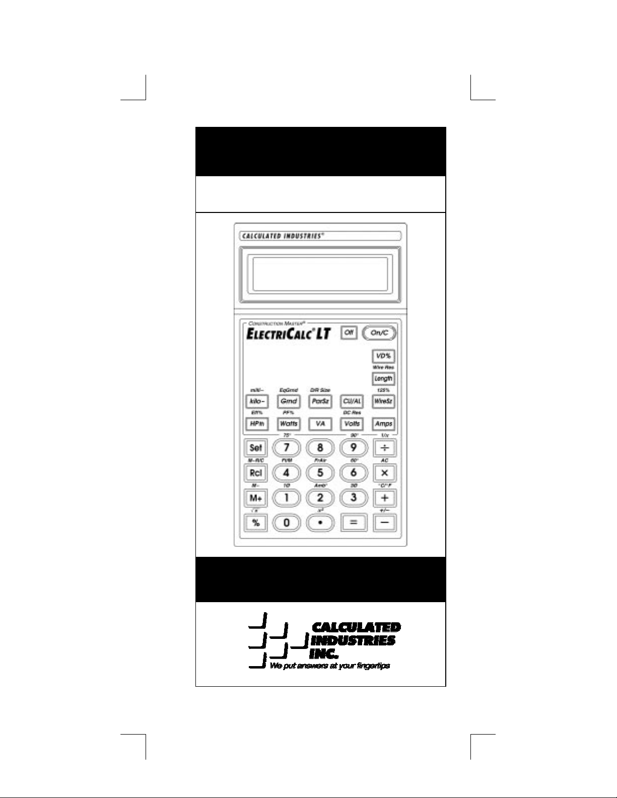
Introducing the
ElectriCalc®LT
The
calculator for today’s busy electrical
professional. Unlik e a regular calc ulator,
it has intuitively labeled “electrical keys”
and conforms to the 1999
Electrical Code,
Code-related problems quickly and
accurately. Common NEC tables are
built in, providing instant solutions for
the following:
♦
♦
♦
ElectriCalc®LT
Volts, Amps, Volt-Amps, Watts,
kVA, kW, PF%, EFF%, and DC
Resistance
Copper or Aluminum Wire Sizes
Parallel & Derated Wire Sizes
is an invaluable
National
allowing you to solve
♦
Voltage Drop Wire Sizes, % and
Actual Voltage Drops, Voltage
Drop Distances and Wire Resis-
tances
♦
Grounding Conductors Sizes
♦
And much more!
User's Guide — 1
Page 4

Table of Cont ents
................................
.................
................................
..............
................................
..
................................
......
................................
.........
................................
................
................................
.....
................................
...................
................................
.....................
................................
.....
................................
........
................................
...........................
................................
..........................
................................
..................
Key Definitions
Default Settings
Basic Math Operations
Percent Calculations
Memory Functions
Kerchoff’s Law
Ampacity Wire Sizing
Voltage Drop
Error Codes
1999 NEC References
Battery Informa ti o n
Settings
3
16
17
17
18
19
24
31
39
39
40
40
Warranty
Legal Notices
2 — ElectriCalc LT
41
45
Page 5

Key Definiti ons
Standard Calculator Functions
[On/C] — On/Clear
Turns on power. Pressing once clears
the last entry and the display. Pressing
twice clears all non-permanent values.
[Off] — Off
Turns all power off. Clears the mem ory
and most internal registers.
[Set] — Second Function
Accesses the secondary functions
shown above the keys when pressed
prior to selection.
[Rcl] — Recall
Recalls a value stored in a register
(e.g., to recall voltage drop % press
[Rcl] [VD%]).
[Rcl] [Rcl] — Display/Clear Memory
Displays and clears the value saved in
(M+).
[Set] [Rcl] — Clear Memory
Clears the value saved in [M+] without
changing displayed value.
User's Guide — 3
Page 6

[M+] — Cumulative Memory
Adds displayed value to Memory (e.g.,
10 [M+], 20 [M+], [Rcl] [M+] = 30).
Clears when the calculator is shut off.
[Set] [M+] — Memory Minus (M−)
Subtracts the displayed value from
Memory.
[+] [–] [x] [÷] [=]
Arithmetic operation keys.
[Set] [–] — Change Sign (+/–)
Toggles the sign of the displayed value
(from positive to negative or from negative to positive).
[Set] [÷] — Reciprocal (1/x)
Reciprocal, or 1/x function.
[0] – [9] & [ • ]
Digits used for keying in numbers.
[Set] [ . ] — x
2
Squares the displayed value.
[%] — Percent
Four function percent key.
[Set] [%] — Square Root (
x )
Square root function.
4 — ElectriCalc LT
Page 7

Mode "Set-Up" Functions
[Set] [x] — All-Clear (AC)
Resets all settings and values to their
default settings.
[CU/AL] — Copper/Aluminum
Used to toggle between copper (default)
and aluminum wire types. When the
wire type is revised, any calculated wire
size will be re-calculated automatically.
If a wire size is entered with the wrong
wire type, pressing
the material type without changing the
size.
Displays: Al
or
[CU/AL]
Cu
will change
[Set] [1] — Single-Phase (1Ø)
Sets calculator to single-phase mode.
Displays: 1Ø.
[Set] [3] — Three-Phase (3Ø)
Sets calculator to three-phase mode.
Displays: 3Ø.
[Set] [6] — 60°C Wire Insulation
Sets calculator to 60°C wire insulation
type for wire size calculations. This is
the default setting.
[Set] [7] — 75°C Wire Insulation
Sets calculator to 75°C insulation type
for wire size calculations.
Displays: 60.
Displays: 75.
User's Guide — 5
Page 8

[Set] [9] — 90°C Wire Insulation
Sets calculator to 90°C insulation type
for wire size calculations. Displays: 90.
[Set] [2] — Ambient Temperature
Permanently enters ambient temperature for determining ampacity derived
wire sizes. Ambient temperature will
only change when entering a new value
or by resetting the calculator ([Set] [x]).
Defaults to 30°C (86°F). Amb° will display when the ambient temperature is
other than 30°C (86°F).
Displays: Amb°.
[Set] [4] — Feet/Meters Toggle
Toggles between feet and meters.
Displays: FEET or MET.
[Set] [5] — Free Air (FrAir)
Sets calculator into Free Air mode,
which refers to NEC Table 310-17 for
wire size calculations. Revises back to
Raceway mode when calculator is powered down. Displays: FrAir.
[Set] [+] — °C/°F Toggle
Toggles ambient temperature format
between °C and °F. Converts displayed
temperature value automatically.
Displays: °C or °F.
6 — ElectriCalc LT
Page 9

Electrical Functions
[kilo-] — Kilo-
This key is used with watts, amps, volts,
and volt-amps to identify "kilo-" values.
[Set] [kilo-] — Milli-
This key is used with other keys watts,
amps, volts, and volt-amps to identify
"milli-" values.
[Amps] — Amps
Enters or calculates amps (using volts
and VA or watts).
KAMP.
[Volts] — Volts
Enters or calculates volts (using amps,
HPth, and VA or watts). Default value is
240 volts.
Displays: VOLT, KV, or mV.
Displays: AMPS,
[Set] [Volts] — DC Resistance
Calculates and displays DC resistance.
Displays: OHMS.
[VA] — Volt-Amps
Enters or calculates volt-amps (using
amps, volts and horsepower or watts).
Displays: VA, KVA, or mVA.
User's Guide — 7
Page 10

[Watts] — Watts
Enters or calculates watts (using amps,
volts, and VA or horsepower).
Displays: WATT, KW, or mW.
[Set] [Watts] —Power Factor
Enters or calculates power factor percentage (based on watts and VA). Defaults to 100%. Entered or calculated
power factors greater than 100% will
result in an error. Displays: PF%.
[HPth] — Horsepower (Theoretical)
Enters or calculates theoretical horsepower (based on Amps, VA, watts, efficiency%, PF%, and/or volts). 1.0 HPth
correlates to 746 watts at 100% efficiency. Displays: HPth.
NOTE: This horsepower should not be
confused with the motor horsepower
keys used to determine motor load.
[Set] [HPth] — Efficiency
Enters or calculates the percent ratio
between real power (watts) and theoretical horsepower. Default: 100%. Entered or calculated efficiencies greater
than 100% will result in an error. Dis-
plays: EFF%.
8 — ElectriCalc LT
Page 11

Ampacity Tables
The
310-16 (310-17 for Free Air) to find wire
sizes and ampacity ratings of wires. The
calculator uses the following data to
calculate wire size: 1) insulation temperature rating (60°C, 75°C and 90°C),
2) wire material (copper or aluminum),
and 3) ambient temperature. Only standard AWG wire sizes are used by the
ElectriCalc LT
uses NEC Table
ElectriCalc LT.
NOTE:
1/0, 2/0, 3/0 and 4/0 wires are
entered using the [0] key (i.e., 0, 00, 000
and 0000).
[WireSz] — Wire Size/Ampacity
Enters or calculates wire size based on
ampacity and voltage drop, if a voltage
drop length has been entered.
♦
First Press
If a wire length has been entered, the
first press will show the larger of the
ampacity or voltage drop derived wire
size. The calculator will use the larger
value when calculations require a wire
size. If no voltage drop length has been
entered, the calculator will display the
calculated ampacity rated wire size.
User's Guide — 9
Page 12

♦
Second Press
If a wire length has been entered, the
second press displays the smaller of the
two wire sizes. If not solving for voltage
drop wire size, then displays the maximum amp acity.
♦
Third Press
If a wire length has been entered, displays the minimum wire ampacity rating.
[Set] [WireSz] — 125% Ampacity
Operates same as [W ireS z], except that
a factor of 125% is applied to the amperage.
[ParSz] — Parallel Size
Used to find the size of parallel conductors using amperage and an entered
quantity of wires. Parallel wire size
computations smaller than 1/0 are displayed as “nonE” as the NEC does not
allow parallel wire runs smaller than 1/0.
NOTE
: No adjustments are made for
deration
♦
.First Press
When preceded by a number, calculates the applicable wire size for that
quantity of wires in parallel.
Displays: PAR WIRE SIZE.
♦
Second Press
10 — ElectriCalc LT
Page 13

Displays the maximum adjusted ampacity of the calculated parallel wire
size. Displays: WIRE A.
NOTE:
Some areas may not allow paralleling conductors. Users must know
the jurisdiction requirements for their
area.
[Set] [ParSz] — Derated Wire Size
Used to calculate derated wire sizes
and allowable ampacity based on the
entered quantity of wires, NEC Table
310-16 and NEC Table 310-15(b)(2)(a).
Derated wire sizes are not calculated
when there are less than 4 wires, or
when the unit is in Free Air mode.
♦
First Press
Calculates the derated wire size, if you
have entered the number of wires, for
example, 4 [Set] [ParSz]).
Displays: D/R WIRE SIZE
♦
Second Press
Displays the maximum adjusted ampacity of the derated wire size.
Displays: D/R WIRE A
♦
Third Press
Displays the derated adjustment factor
per the NEC Table 310-15(b)(2)(a).
Displays: ADJ %
User's Guide — 11
Page 14

Voltage Drop Solutions
The
mum lengths, minimum wire sizes or
actual voltage drops given the other two
values. Voltage drop solutions are
based on the DC resistance values
found in NEC Chapter 9, Table 8.
NOTE
ElectriCalc LT
: Voltage drop solutions may vary
will calculate maxi-
slightly from actual AC circuit val ues as
factors such as inductive reactance,
skin effect, raceway material, etc., are
not considered
[VD%] — Percent Voltage Drop
Used to enter or calculate voltage drop.
The default voltage drop is 3%. If wire
size or wire length values are not avai lable, “nonE” will display since the voltage drop cannot be found.
♦
First Press
Enters a maximum allowable voltage
drop percentage
or calculates actual voltage drop
%)
Displays: V DROP
♦
Second Press
Calculates actual percent voltage drop.
Displays: V DROP %
(Displays: V DROP
12 — ElectriCalc LT
Page 15

[Length] — Length
Enters or calculates the maximum
length of run for voltage drop computation. Displays: FEET or MET
[Set] [Length] — Wire Resistance
Displays the wire resistance per 1,000
feet of the wire size in [WireSz] based
on NEC Chapter 9, Table 8.
Displays: OHMS WIR E
User's Guide — 13
Page 16

Ground Function Keys
[Grnd] — Ground
An output-only key used to find the
grounding electrode conductor size for
AC systems based on NEC Table
250-66 and an entered or calculated
service-entrance conductor (largest
size). Only actual wire sizes are considered valid entries.
♦
First Press
Calculates the copper grounding electrode conductor size if you have entered
a valid wire size.
Displays: GRND CU WIRE SIZE
♦
Second Press
Displays the aluminum grounding electrode conductor size.
Displays: GRND AL WIRE SIZE
♦
Third Press
Displays the circular mil area used to
calculate the grounding electrode conductor size.
Displays: CMIL WIRE
14 — ElectriCalc LT
Page 17

[Set] [Grnd] — Equipment Ground
(EqGrnd)
This function uses NEC Table 250-122
to compute the minimum equipment
grounding conductor size, given an
entered amperage rating or setting for a
over-current device up line (i.e., 300
[Set] [Grnd]).
NOTE
: This function deviates from the
NEC Table 250-122 for Amp values of
4001 or more. The AL conductor sizes
given in the Table (1200 MCM AL) are
not among those listed in Table 31016/17, which is the table the calculator
uses to calculate wire size. In these
cases, the calculator gives a slightly
larger 1250 MCM AL as the appropriate
Equipment Ground wire size.
♦
First Press
Displays the copper grounding conductor size for the entered amp rating.
Displays: EQPG WIRE SIZE CU
♦
Second Press
Displays the aluminum grounding conductor size.
Displays: EQPG WIRE SIZE AL
User's Guide — 15
Page 18

Default Settings
W hen you first receive your calculator, it
is pre-set to the default settings listed
below. You can always return your calculator to these default values with an
All-Clear
Ambient Temperature 30°C
Insulation Rating 60°C
Material Copper (Cu)
Phase 3Ø
Volts 240 V
Efficiency 100%
Power Factor 100%
([Set] [x])
.
Length Units Feet
Voltage Drop Percent 3%
Wire Environment Raceway
(vs Free Air)
16 — ElectriCalc LT
Page 19

Basic Math Operations
This calculator uses standard chaining
logic, which simply means that you enter
your first value, the operator (+, –, x, ÷),
the second value and then the equals
sign (=).
A. 3 [+] 2 [=] 5
B. 3 [–] 2 [=] 1
C. 3 [x] 2 [=] 6
D. 3 [÷] 2 [=] 1.5
Percent Calcul ations
The percent key
finding a given percentage of a number
or for working add-on, discount or division percentage calculations.
355 [x] 15 [%] 53.25
250 [+] 6.5 [%] 266.25
25 [–] 5 [%] 23.75
100 [÷] 50 [%] 200.
The percent key also allows you to
change percentages to decimals (e.g.,
25 [%] 0.25).
can be used for
[%]
User's Guide — 17
Page 20

Memory Functions
W henever the
displayed value will be added to memory. Other memory functions:
Function Keystrokes
Subtract from memory
Recall total in memory
Display & clear memory
Clear memory, no display
Replace memory with
displayed value
The memory is semi-permanent; it will
be cleared when you:
1) turn off the calculator;
2) press
3) press
4) press
[M+]
[Rcl] [Rcl]
[Set] [Rcl];
[Set] [x]
key is pressed, the
[Set] [M+]
[Rcl] [M+]
[Rcl] [Rcl]
[Set] [Rcl]
[Set] [Rcl] [M+]
;
(all clear).
How To Use Memory Functions:
Steps Keystrokes Display
Add to M+ 355 [M+] 355.
Add to M+ 255 [M+] 255.
Recall total M+ [Rcl] [M+] 610.
Sub. from M+ 745 [Set] [M+] 745.
Recall & clear [Rcl] [Rcl] – 135
18 — ElectriCalc LT
Page 21

Kerchoff’ s Law
The
Law in finding volts, amps, volt-amps,
watts, horsepower (theoretical), efficiency and power factor.
ElectriCalc LT
utilizes Kerchoff’s
Finding Voltage
Find the voltage supply to a singlephase load drawing 14,605 volt-amps
and 115 amps.
Steps
Clear calculator [On/C] [On/C] 0.
Set to 1-phase [Set] 1 1 PH
Enter volt-amps 14605 [VA] 14,605. VA
Enter amps 115 [Amps] 115. AMPS
Solve for volts [Volts] 127. VOLT
Keystrokes
Display
Finding Amps
What is the current (amps) for a load
drawing 8,250 volt-amps on a 240 volt,
three-phase circuit?
Steps
Clear calculator [On/C] [On/C] 0.
Set to 3-phase [Set] 3 3 PH
Enter volt-amps 8250 [VA] 8250. VA
Enter volts 240 [Volts] 240. VOLT
Solve for amps [Amps] 19.846416 AMPS
Keystrokes
User's Guide — 19
Display
Page 22

Finding Current Load
A building with 120/240 volt 1Ø service
has the following loads:
Range = 7,800 VA
Heating = 15,100 VA
Dryer = 5,100 VA
Fixed Appliances = 8,900 VA
General Lighting = 6,470 VA
What is the service load (amps) of the
circuit supplying this building?
Steps
Clear calculator [On/C] [On/C] 0.
Set to 1-phase [Set] 1 1 PH
Add VA loads: 7,800 +
Enter as VA [VA] 43,370. VA
Enter volts 240 [Volts] 240. VOLT
Solve for amps [Amps] 180.70833 AMPS
Keystrokes
15,100 +
5,100 +
8,900 +
6,470 [=] 43,370
Display
20 — ElectriCalc LT
Page 23

Finding Amps from Kilowatts
W hat is the amperage for a 75 kW load
connected in a 120/208 volt, 3Ø circuit?
Steps
Clear calculator [On/C] [On/C] 0.
Set to 3-phase [Set] 3 3 PH
Enter kilowatts 75 [kilo-] [Watts] 75. KW
Enter volts 208 [Volts] 208. VOLT
Solve for amps [Amps] 208.17918 AMPS
Keystrokes
Display
Finding Volt-Amps
W hat is the VA rating for a 120 volt, 22
amp, 1Ø circuit? What is the kVA rating?
Steps
Clear calculator [On/C] [On/C] 0.
Set to 1-phase [Set] 1 1 PH
Enter volts 120 [Volts] 120. VOLT
Enter amps 22 [Amps] 22. AMPS
Solve volt-amps [VA] 2,640. VA
Solve for kVA [kilo-] [VA] 2.64 KVA
Keystrokes
Display
User's Guide — 21
Page 24

Finding kVA Rating
What is the kVA rating for a 120/208
volt, three-phase 65 amp transformer?
Steps
Reset calculator [Set] [x] 0.
Enter volts 208 [Volts] 208. VOLT
Enter amps 65 [Amps] 65. AMPS
Solve for kVA [kilo-] [VA] 23.417327 KVA
Keystrokes
Display
Finding Wattage
A 120 volt single-phase 45 amp electrical motor has an 87% power factor.
What is its wattage?
Steps
Clear calculator [On/C] [On/C] 0.
Set to 1-phase [Set] 1 1 PH
Enter volts 120 [Volts] 120. VOLT
Set power fact % 87 [Set] [Watts] 87 PF%
Enter amps 45 [Amps] 45. AMPS
Solve for watts [Watts] 4,698. WATT
Keystrokes
Display
22 — ElectriCalc LT
Page 25

Finding kW Rating
W hat’s the kW rating for a 90 am p, 208
volt, three-phase broiler with 100%
power factor?
Steps
Clear calculator [On/C] [On/C] 0.
Set to 3-phase [Set] 3 3 PH
Set power factor 100 [Set] [Watts] 100 PF%
Enter amps 90 [Amps] 90. AMPS
Enter volts 208 [Volts] 208. VOLT
Solve for kW [kilo-] [Watts]32.423991 KW
Keystrokes
Display
User's Guide — 23
Page 26

Ampacity Wire Sizing
The required wire size of a service conductor can be determined based on the
specified electrical requirements and
the [WireS z] key. The wire size is automatically recalculated whenever the
wire insulation (temperature) ratings or
wire material (copper or aluminum)
types are revised. Wire sizing is based
on the requirements defined in NEC
Tables 310-16 and 310-17.
Wire Sizing Based
on Insulation Rating
Wiring is being installed in a 240 volt,
single-phase system rated at 30 kVA.
W hat is the wire size needed if you use
60°C copper wire?
Steps
Clear calculator [On/C] [On/C] 0.
Set to 1-phase [Set] 1 1 PH
Set to 60
Enter kVA 30 [kilo-] [VA] 30. KVA
Enter volts 240 [Volts] 240. VOLT
Find amps [Amps] 125. AMPS
Find CU wire size [WireSz] 0 CU
Û&
Keystrokes
[Set] 6 1Ø 60 Cu 1 PH
AWG WIRE SIZE
Display
24 — ElectriCalc LT
Page 27

Re-sizing Wire Based on
Different Insulation Ratings
What wire size is required for a 75°C
copper branch circuit carrying a load of
260 amps? What would the wire size be
if 90°C copper is used?
Steps
Reset calculator [Set] [x] 0.
Set to 75°C [Set] 7 3Ø 75 Cu 0.
Enter amps 260 [Amps] 260. AMPS
Find wire size [WireSz] 300 CU
Change to 90
Keystrokes
AWG WIRE SIZE
Û
[Set] 9 0000 CU
AWG WIRE SIZE
Display
User's Guide — 25
Page 28

Wire Sizing Based
on Ambient Temperature
Find the 90°C aluminum wire size
needed to connect a 47,700 volt-amp
load to a 240 volt, single-phase source.
Steps
Clear calculator [On/C] [On/C] 0.
Set to 1-phase [Set] 1 1 PH
Set to 90°C [Set] 9 1 Ø 90 Cu 1 PH
Set to alum. [CU/AL] 1 Ø 90 Al 1 PH
Enter volt-amps 47700 [VA] 47,700. VA
Enter volts 240 [Volts] 240. VOLT
Find amps [Amps] 198.75 AMPS
Find wire size [WireSz] 0000 AL
What is the adjusted wire size, if the
ambient temperature rating is changed
from the default 30°C to 40°C?
Change ambient
temperature 40 [Set] [2] AMB° 40
Find adjusted
wire size [WireSz] 250 AL
Keystrokes
AWG WIRE SIZE
AWG WIRE SIZE
Display
Û&
NOTE: Ambient temperature will remain at 40°C
unless you change it or per form an ALL CLEAR
([Set] [x]).
Reset amb. temp 30 [Set] [2] AMB° 30
Û&
26 — ElectriCalc LT
Page 29

Wire Sizing Based on
Material Type
Find the wire size for a 75°C copper
wire carrying a 3Ø load of 265 amps.
What is the equivalent aluminum wire
size?
Steps
Reset calculator [Set] [x] 0.
Set to 75°C [Set] 7 3Ø 75 Cu 0.
Enter amps 265 [Amps] 265. AMPS
Find wire size [WireSz] 300 CU
Change to alum. [CU/AL] 400 AL
Keystrokes
AWG WIRE SIZE
AWG WIRE SIZE
Display
User's Guide — 27
Page 30

Sizing Parallel Conductors
W hat size 60°C insulated copper wire is
required for a single conductor carrying
a 500 amp load in a Free Air environment (30°C amb. tem p.)? What size for
2 parallel conductors? For 3 conductors?
Steps
Reset calculator [Set] [x] 0.
Set free air mode [Set] 5 3Ø 60 FrAir Cu 0.
Enter amps 500 [Amps] 500. AMPS
Find 1 wire size [WireSz] 500 CU
Find 2 wire size 2 [ParSz] 000 CU
Find 3 wire size 3 [ParSz] 0 CU
Keystrokes
AWG WIRE SIZE
Display
PAR WIRE SIZE
PAR WIRE SIZE
NOTE: Parallel wire sizes smaller than
1/0 will be displayed as nonE.
28 — ElectriCalc LT
Page 31

Finding Derated Wire Size
What is the derated wire size required
for nine 75°C copper wires, each carrying a maximum load of 65 amps?
Steps
Reset calculator [Set] [x] 0.
Set to 75°C [Set] 7 3Ø 75 Cu 0.
Enter amps 65 [Amps] 65. AMPS
Find normal
wire size [WireSz] 6 CU
Find derated
wire size 9 [Set] [ParSz] 3 CU
Keystrokes
AWG WIRE SIZE
Display
D/R WIRE SIZE
User's Guide — 29
Page 32

Sizing Temp eratu re-Adjusted
Derated Wi res
A circuit was built with 90°C aluminum
wire connecting a 47,650 volt-amp load
to a 240 volt, single-phase source. Ambient temperature is 50°C. What is the
derated wire size required if eight current-carrying THHN wires were installed
in the raceway?
Steps
Reset calculator [Set] [x] 0.
Set to 1-phase [Set] 1 1 PH
Set to 90°C [Set] 9 1Ø 90 Cu 1 PH
Toggle to alum. [CU/AL] 1Ø 90 Al 1 PH
Enter volt-amps 47650 [VA] 47,650. VA
Enter volts 240 [Volts] 240. VOLT
Set to 50°C amb 50 [Set] [2] AMB° 50
Find adjst wire sz. [WireSz] 300 AL
Find derated 8 [Set] [ParSz] 500 AL
wire size D/R WIRE SIZE
NOTE:
Ambient temperature should be
Keystrokes
AWG WIRE SIZE
Display
Û&
changed back to 30°C to avoid confl icts
in answers through out the rest of this
manual.
Reset to 30°C 30 [Set] [2] AMB° 30
30 — ElectriCalc LT
Û&
Page 33

Voltage Drop
The reduction in voltage between the
power source and the load can be determined by entering the phase, volts,
amps, wire material, voltage drop wire
size and length of run. The calculator
determines resistance and then the
voltage reduction. Voltage drop can be
displayed as volts dropped, or as a
percent reduction of potential load.
This calculator also finds voltage drop
wire size once you have entered or
calculated the phase, volts, amps,
length, wire type, and allowable VD
percentage. It will solve for the distance
([Length]) once you have entered or
calculated the phase, volts, amps, wire
type, voltage drop wire size, and allowable VD percentage. T he
uses resistance values found in NEC
Table 8 to determine voltage drop.
ElectriCalc LT
NOTE
: Voltage drop solutions may vary
slightly from actual AC circuit measurements as the calculator does not incorporate factors such as inductive reactance, skin effect, raceway material, etc.
In most situations, the DC Voltage Drop
calculation is sufficient to meet safety
standards.
User's Guide — 31
Page 34

IMPORTANT NOTE ON
VOLTAGE DROP CALCULATIONS
The
drop and wire size using DC resistance
values as defined by the 1999 NEC. To
find the voltage drop for a
size, you must
other required variables), then enter the
specific wire size. Otherwise, if amps
are entered last, the calculator will recalculate the wire size to match the ‘99
NEC Ampacity Table requirements.
ElectriCalc LT
calculates voltage
specific
first enter amps
wire
(and the
Finding Single-Phase
Voltage Drop
You are installing 175 feet of 75°C, 8
THW branch circuit copper conductors
to supply an 11-amp load on a 208-volt
1Ø system. W hat is the source voltage
drop at the load? What is the percentage?
Steps
Reset calculator [Set] [x] 0.
Set to 1-phase [Set] 1 1 PH
Set to 75°C [Set] 7 1Ø 75 Cu 1 PH
Enter amps 11 [Amps] 11. AMPS
Enter volts 208 [Volts] 208. VOLT
Enter length 175 [Length] 175. FEET
(Cont’d)
Keystrokes
Display
32 — ElectriCalc LT
Page 35

Steps
Enter wire size 8 [WireSz] 8 CU
Solve volt. drop [VD%] 3.0 DROP V
Solve % v.drop [VD%] 1.4 DROP V %
Keystrokes
AWG WIRE SIZE
Display
Finding Three-Phase
Voltage Drop
A 20-amp three-phase load is being fed
by a 230-volt source located 150 feet
away. The installation specifications
require 75°C #10 THW stranded copper
conductor. What is the voltage drop on
this branch circuit?
Steps
Reset calculator [Set] [x] 0.
Set to 75°C [Set] 7 3Ø 75 Cu 0.
Enter amps 20 [Amps] 20. AMPS
Enter volts 230 [Volts] 230. VOLT
Enter length(feet) 150 [Length] 150. FEET
Enter VD wire size10 [WireSz] 10 CU
Find VD [VD%] 6.4 DROP V
Find VD% [VD%] 2 .8 DROP V %
Keystrokes
AWG WIRE SIZE
Display
User's Guide — 33
Page 36

Finding Voltage Drop Wire Size
A 20-amp single-phase 208-volt load
will be located 175 feet away from the
source. Assuming a 3% allowable voltage drop, what is the size of 75°C conductor required for this branch circuit?
Steps
Reset calculator [Set] [x] 0.
Set to 75°C [Set] 7 3Ø 75 Cu 0.
Set to single ph. [Set] 1 1 PH
Enter amps 20 [Amps] 20. AMPS
Enter volts 208 [Volts] 208. VOLT
Enter distance 175 [Length] 175. FEET
Enter allow. VD% 3 [VD%] 3 DROP V %
Find wire size [WireSz] 8 CU
Find actual
voltage drop [VD%] 5.4 DROP V
Find % v.drop [VD%] 2.6 DROP V %
Keystrokes
AWG WIRE SIZE
Display
34 — ElectriCalc LT
Page 37

Finding Voltage Drop Distance
How far from a single-phase 240-volt
source can you install a 15 amp load
using 60°C #10 Al branch circuit conductors? Assume a 3% allowable voltage drop.
Steps
Reset calculator [Set] [x] 0.
Set to single ph. [Set] 1 1 PH
Set to aluminum [CU/AL] 1Ø 60 Al 1 PH
Enter amps 15 [Amps] 15. AMPS
Enter volts 240 [Volts] 240. VOLT
Enter wire size 10 [WireSz] 10. AL
Enter 3% VD 3 [VD%] 3. DROP V %
Find distance [Length] 123.77387 FEET
Find actual
voltage drop [VD%] 7.2 DROP V
Find % v.drop [VD%] 3.0 DROP V
NOTE
: The calculator automatically
Keystrokes
AWG WIRE SIZE
Display
makes adjustments for resistance using
NEC Chap 9, Table 8, if the insulation
type is other than 75°C.
User's Guide — 35
Page 38

Finding Voltage Drop
Resistance
What is the resistance of 85 feet of #2
90°C copper conductor?
Steps
Reset calculator [Set] [x] 0.
Set to 90°C mode [Set] 9 3Ø 90 Cu 0.
Enter wire size 2 [WireSz] 2 CU
Find resistance [Set] [Length] 0.2033993
Find 85 ft resist* [÷] 1000 [x] 85 [=] 0.0172889
NOTE
*
: Given resistance per 1000 feet,
Keystrokes
AWG WIRE SIZE
Display
OHMS WIRE
divide by 1000 to get a per foot resistance, then multiply by 85.
Finding DC Resistance
What is the equivalent resistance of a
12 volt DC circuit pulling 5 amps?
Steps
Reset calculator [Set] [x] 0.
Enter voltage 12 [Volts] 12 VOLT
Enter amps 5 [Amps] 5. AMPS
Find resistance [Set] [Volts] 2.4 OHMS
Keystrokes
Display
36 — ElectriCalc LT
Page 39

Ground Conductor Wire Size
You can use single or multiple service
entrance conductor(s) to find the
grounding electrode conductor for AC
systems. When using multiple conductors, the
equivalent circular mils to find the
grounding electrode conductor (based
on NEC Table 250-66).
Find the grounding electrode conductor
wire size required when 2/0 is the largest 3-phase 75°C copper serviceentrance conductor being used. What is
the equivalent aluminum size? What is
the equivalent circular mils?
ElectriCalc LT
uses the
Steps
Reset calculator [Set] [x] 0.
Set cond. temp. [Set] 7 3Ø 75 Cu 0.
Enter wire size 00 [WireSz] 00 CU
Find grnd wire sz [Grnd] 4 CU
Find alum size [Grnd] 2 AL
Find circular mils [Grnd] 133,100.
Keystrokes
AWG WIRE SIZE
GRND WIRE SIZE
GRND WIRE SIZE
Display
CMIL WIRE
User's Guide — 37
Page 40

Equipment Grounding
Conductor Wire Size
The [Set] [Grnd] keystroke can be used
to find the grounding conductor size for
raceways and “over-current devices in
circuit ahead” equipment. The cal culator
uses the displayed amperage value to
solve for the equipment grounding conductor based on NEC Table
250-122.
Find the equipment grounding conductor size required when the circuitbreaker is rated at 45 amps and 90°
copper is being used in the installation.
What is the equivalent aluminum size?
Steps
Reset calculator [Set] [x] 0.
Set cond. temp. [Set] 9 3Ø 90 Cu 0.
Enter amp rating 45 [Amps] 45. AMPS
Find equip. grnd.
wire size [Set] [Grnd] 10 CU
Find alum size [Grnd] 8 AL
Keystrokes
EQPG WIRE SIZE
EQPG WIRE SIZE
Display
38 — ElectriCalc LT
Page 41

Error Codes
The error codes for the
are listed below (Note: To clear an error,
simply press any key):
Error Description
1 Display register overflow
(Answer too large to fit display)
2 Invalid or out-of-scale entry
3 PF or EFF calculated above 100%
5 Unable to calculate VDWire Size
(Amps/Length too high)
9 Entered or calculated more than 15 dif-
ferent wires sizes
11 Temperature setting out of range for wire
computation.
ElectriCalc LT
1999 NEC References
Table 250-66
Table 250-122
Table 310-15(b)(2)(a)
Table 310-16
Table 310-17
Chapter 9, Tables 1, 4, 5 and 8
Appendix C
User's Guide — 39
Page 42

Battery Information
The calculator is powered by a single 3Volt Lithium CR-2032 battery. This
should last upwards of 800 hours of
actual use (1 year plus for m ost peopl e).
If the display becomes very dim or erratic, replace the battery.
NOTE:
posing of your old batteries as they
contain hazardous chemicals.
Please use caution when dis-
Settings
Permanent Values/Settings
Values and settings maintained in permanent memory can only be changed
(1) by pressing
lator to default settings), or (2) by
changing each one or all of these settings. The following are permanent values:
(1) Selectable (60°C/75°C/90°C) insulation
ratings and CU/AL wire type ratings
(2) Phase setting (1Ø/3Ø)
[Set] [x]
(resets calcu-
(3
) The entered values for volts,
voltage drop %, power factor %
and efficiency %
40 — ElectriCalc LT
Page 43

Semi-Permanent Values
The following semi-permanent values
are cleared to default settings when the
calculator is shut off:
(1) Independent User Memory
(2) Free Air mode
Warranty
Warranty Repair Service –
U.S.A.
Calculated Industries, Inc. ("CII") warrants this product against defects in
materials and workm anship for a period
of one (1) year from the date of original
consumer purchase in the U.S. If a
defect exists during the warranty period,
CII at its option will either repair (using
new or remanufactured parts) or replace
(with a new or remanufactured unit) the
product at no charge.
THE WARRANTY WILL NOT APPLY
TO THE PRODUCT IF IT HAS BEEN
DAMAGED BY MISUSE, ALTERATION, ACCIDENT, IMPROPER HANDLING OR OPERATION, OR IF UNAUTHORIZED REPAIRS ARE ATTEMPTED OR MADE. SOME EXAMPLES OF DAMAGES NOT COVERED
BY WARRANTY INCLUDE, BUT ARE
NOT LIMITED TO, BATTERY LEAKAGE, BENDING, OR VISIBLE
User's Guide — 41
Page 44

CRACKING OF THE LCD, WHICH
ARE PRESUMED TO BE DAMAGES
RESULTING FROM MISUSE OR
ABUSE.
To obtain warranty service in the U.S.,
ship the product postage paid to the CII
Authorized Service Provider listed on
the back page of the User’s Guide.
Please provide an explanation of the
service requirement, your name, address, day phone number and dated
proof of purchase (typically a sales receipt). If the product is over 90 days old,
include payment of $6.95 for return
shipping and handling within the contiguous 48 states. (Outside the contiguous 48 states, please call CII for return
shipping costs.)
A repaired or replacement product assumes the remaining warranty of the
original product or 90 days, whichever is
longer.
Non-Warrant y Repair Service
– U.S.A.
Non-warranty repair covers service
beyond the warranty period or service
requested due to damage resulting from
misuse or abuse.
Contact the CII Authorized Service Provider listed on the back page of the
User’s Guide to obtain current product
42 — ElectriCalc LT
Page 45

repair information and charges. Repairs
are guaranteed for 90 days.
Repair Service
– Outside the U.S.A.
Not all countries have CII Authorized
Service Providers or the same warranty
and service policies. To obtai n warranty
or non-warranty repair service for goods
purchased outside the U.S., contact the
dealer through which you initially purchased the product. If you cannot reasonably have the product repaired in
your area, you may contact CII to obtain
current product repair information and
charges, including freight and duties.
Disclaimer
CII MAKES NO W ARRANTY OR REPRESENTATION, EITHER EXPRESS
OR IMPLIED, WITH RE-SPECT TO
THE PRODUCT’S QUALITY, PERFORMANCE, MERCHANTABILITY, OR
FITNESS FOR A PARTICULAR PURPOSE. AS A RESULT, THIS PRODUCT, INCLUDING BUT NOT LIMITED
TO, KEYSTROKE PROCEDURES,
MATHEMATICAL ACCURACY AND
PREPROGRAMMED MATERIAL, IS
SOLD "AS IS," AND YOU THE PURCHASER ASSUME THE ENTIRE RISK
AS TO ITS QUALITY AND PERFORMANCE.
User's Guide — 43
Page 46

IN NO EVENT WILL CII BE LIABLE
FOR DIRECT, INDIRECT, SPECIAL,
INCIDENTAL, OR CONSEQUENTIAL
DAMAGES RESULTING FROM ANY
DEFECT IN THE PRODUCT OR ITS
DOCUMENTATION.
The warranty, disclaimer, and rem edies
set forth above are exclusive and replace all others, oral or written, expressed or implied. No CII dealer,
agent, or employee is authorized to
make any modification, extension, or
addition to this warranty.
Some states do not allow the exclusion
or limitation of implied warranties or
liability for incidental or consequential
damages, so the above limitation or
exclusion may not apply to you. This
warranty gives you specific rights, and
you may also have other rights which
vary from state to state.
FCC Class B
This equipment has been certified to
comply with the limits for a Class B
computing device, pursuant to Subpart
J of Part 15 of FCC rules.
44 — ElectriCalc LT
Page 47

Legal Notices
Software copyrighted and licensed to
Calculated Industries, Inc. by Specialty
Calculator Technologies, LLC, 1999.
User’s Guide is copyrighted by Calculated Industries, Inc., 1999.
ElectriCalc LT and Calculated Industries
are registered trademarks of Calcul ated
Industries, Inc.
ALL RI GHTS RESERVED
Calculated Industries, Inc.
4840 Hytech Drive
Carson City, NV 89706 U.S.A
775/885-4975 • Fax: 775/885-4949
E-mail: techsup@calculated.com
http://www.calculated.com
File: 5025-MN.DOC
User's Guide — 45
Page 48

Designed in the
United States of America
Printed in Indonesia
5025-MN V1.0
 Loading...