

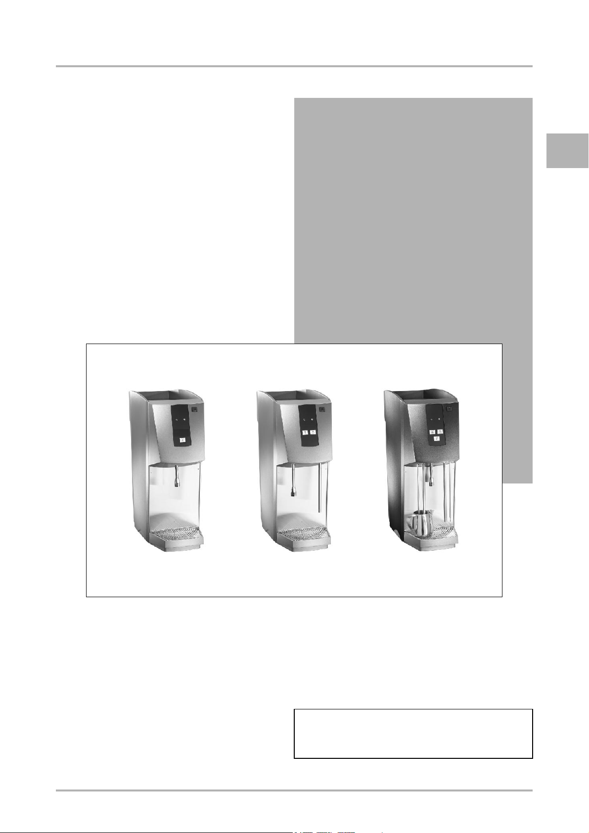
OPERATING INSTRUCTIONS
c5-2
E
Item no. : Cafina - 2954079
Item no. : Melitta SystemService - 2954085
OI c5-2 eng V1 / 08.12.2004 © Cafina / Melitta

E
OPERATING INSTRUCTIONS
RETAIN FOR FUTURE USE!
The copyright of these Operating Instructions, which are entrusted to the recipient personally, remains with the Cafina / Melitta company.
The content may not be disclosed or made available to any third party without the express
consent of the Cafina / Melitta company.
These Operating Instructions must be read and applied by anyone performing work with or
on this equipment.
In particular, it is imperative that all such persons familiarise themselves with the safety
instructions.
© Cafina / Melitta OI c5-2 eng V1 / 08.12.2004

TABLE OF CONTENTS
1 Description
1.1 Design . . . . . . . . . . . . . . . . . . . . . . . . . . . . . . . . . . . . . . . . . . . . . . . . . . . . . 1 - 1
1.1.1 External parts . . . . . . . . . . . . . . . . . . . . . . . . . . . . . . . . . . . . . . . . . . . 1 - 1
1.2 Mode of operation . . . . . . . . . . . . . . . . . . . . . . . . . . . . . . . . . . . . . . . . . . . . 1 - 2
1.2.1 c5-2 boiler element . . . . . . . . . . . . . . . . . . . . . . . . . . . . . . . . . . . . . . 1 - 2
1.2.2 "Temperature probe" option . . . . . . . . . . . . . . . . . . . . . . . . . . . . . . . . 1 - 2
1.3 Technical data . . . . . . . . . . . . . . . . . . . . . . . . . . . . . . . . . . . . . . . . . . . . . . . 1 - 2
1.3.1 Boiler element types . . . . . . . . . . . . . . . . . . . . . . . . . . . . . . . . . . . . . 1 - 2
1.3.2 Machine identification . . . . . . . . . . . . . . . . . . . . . . . . . . . . . . . . . . . . 1 - 3
1.3.2.1 Switzerland . . . . . . . . . . . . . . . . . . . . . . . . . . . . . . . . . . . . . . . 1 - 3
1.3.2.2 Export . . . . . . . . . . . . . . . . . . . . . . . . . . . . . . . . . . . . . . . . . . . 1 - 3
1.3.3 Characteristics . . . . . . . . . . . . . . . . . . . . . . . . . . . . . . . . . . . . . . . . . . 1 - 4
1.3.4 Environmental conditions . . . . . . . . . . . . . . . . . . . . . . . . . . . . . . . . . . 1 - 4
1.3.4.1 Temperature and humidity . . . . . . . . . . . . . . . . . . . . . . . . . . . 1 - 4
1.3.4.2 Space requirements . . . . . . . . . . . . . . . . . . . . . . . . . . . . . . . . 1 - 4
E
2 Safety instructions
2.1 Warnings . . . . . . . . . . . . . . . . . . . . . . . . . . . . . . . . . . . . . . . . . . . . . . . . . . . 2 - 1
2.1.1 Warning symbols used (depending on nationality) . . . . . . . . . . . . . . 2 - 1
2.1.2 Places where warning symbols
are affixed (depending on nationality) . . . . . . . . . . . . . . . . . . . . . . . . 2 - 1
2.1.3 Safety information in these Operating Instructions . . . . . . . . . . . . . . 2 - 1
2.2 Basic safety instructions . . . . . . . . . . . . . . . . . . . . . . . . . . . . . . . . . . . . . . . . 2 - 2
2.2.1 Proper use . . . . . . . . . . . . . . . . . . . . . . . . . . . . . . . . . . . . . . . . . . . . . 2 - 2
2.2.1.1 General . . . . . . . . . . . . . . . . . . . . . . . . . . . . . . . . . . . . . . . . . . 2 - 2
2.2.1.2 c5-2 boiler element . . . . . . . . . . . . . . . . . . . . . . . . . . . . . . . . . 2 - 2
2.2.2 Specific hazards and instructions . . . . . . . . . . . . . . . . . . . . . . . . . . . 2 - 3
2.2.2.1 c5-2 boiler element . . . . . . . . . . . . . . . . . . . . . . . . . . . . . . . . . 2 - 3
2.2.3 Personal safety . . . . . . . . . . . . . . . . . . . . . . . . . . . . . . . . . . . . . . . . . 2 - 4
2.3 Safety mechanisms . . . . . . . . . . . . . . . . . . . . . . . . . . . . . . . . . . . . . . . . . . . 2 - 5
2.3.1 Power switch . . . . . . . . . . . . . . . . . . . . . . . . . . . . . . . . . . . . . . . . . . . 2 - 5
2.3.2 Relief pressure valve . . . . . . . . . . . . . . . . . . . . . . . . . . . . . . . . . . . . . 2 - 5
2.4 Authorised persons . . . . . . . . . . . . . . . . . . . . . . . . . . . . . . . . . . . . . . . . . . . . 2 - 5
2.4.1 General . . . . . . . . . . . . . . . . . . . . . . . . . . . . . . . . . . . . . . . . . . . . . . . 2 - 5
2.4.2 Areas of responsibility of personnel . . . . . . . . . . . . . . . . . . . . . . . . . . 2 - 5
2.4.2.1 Operator . . . . . . . . . . . . . . . . . . . . . . . . . . . . . . . . . . . . . . . . . 2 - 5
2.4.2.2 User . . . . . . . . . . . . . . . . . . . . . . . . . . . . . . . . . . . . . . . . . . . . . 2 - 6
2.4.2.3 Maintenance personnel (service technician) . . . . . . . . . . . . . . 2 - 6
OI c5-2 eng V1 / 08.12.2004 i © Cafina / Melitta

E
TABLE OF CONTENTS
2.4.3 Minimum training and qualifications of authorised personnel . . . . . . 2 - 6
2.4.3.1 Operator . . . . . . . . . . . . . . . . . . . . . . . . . . . . . . . . . . . . . . . . . 2 - 6
2.4.3.2 User . . . . . . . . . . . . . . . . . . . . . . . . . . . . . . . . . . . . . . . . . . . . . 2 - 6
2.4.3.3 Maintenance personnel (service technician) . . . . . . . . . . . . . . 2 - 6
2.5 Maintenance duty . . . . . . . . . . . . . . . . . . . . . . . . . . . . . . . . . . . . . . . . . . . . . 2 - 6
2.6 Availability of these Operational Instructions . . . . . . . . . . . . . . . . . . . . . . . . 2 - 6
3 Controls and indicators
3.1 Key-operated switch . . . . . . . . . . . . . . . . . . . . . . . . . . . . . . . . . . . . . . . . . . . 3 - 1
3.2 Pushbuttons . . . . . . . . . . . . . . . . . . . . . . . . . . . . . . . . . . . . . . . . . . . . . . . . . 3 - 1
3.3 Indicator lamps . . . . . . . . . . . . . . . . . . . . . . . . . . . . . . . . . . . . . . . . . . . . . . . 3 - 1
3.4 Grip elements . . . . . . . . . . . . . . . . . . . . . . . . . . . . . . . . . . . . . . . . . . . . . . . . 3 - 1
3.5 Covers . . . . . . . . . . . . . . . . . . . . . . . . . . . . . . . . . . . . . . . . . . . . . . . . . . . . . 3 - 1
3.6 Operating modes . . . . . . . . . . . . . . . . . . . . . . . . . . . . . . . . . . . . . . . . . . . . . 3 - 2
4 Initial start-up
4.1 Normal initial start-up . . . . . . . . . . . . . . . . . . . . . . . . . . . . . . . . . . . . . . . . . . 4 - 1
4.2 Return to service after the machine
has been out of service for a limited time . . . . . . . . . . . . . . . . . . . . . . . . . . . 4 - 1
4.3 Return to service after a fault . . . . . . . . . . . . . . . . . . . . . . . . . . . . . . . . . . . . 4 - 1
5 Operation
5.1 Power supply connection . . . . . . . . . . . . . . . . . . . . . . . . . . . . . . . . . . . . . . . 5 - 1
5.2 Water connection . . . . . . . . . . . . . . . . . . . . . . . . . . . . . . . . . . . . . . . . . . . . . 5 - 1
5.2.1 Water intake . . . . . . . . . . . . . . . . . . . . . . . . . . . . . . . . . . . . . . . . . . . . 5 - 1
5.2.2 Water drainage . . . . . . . . . . . . . . . . . . . . . . . . . . . . . . . . . . . . . . . . . 5 - 1
5.3 Switching on and off . . . . . . . . . . . . . . . . . . . . . . . . . . . . . . . . . . . . . . . . . . . 5 - 2
5.4 Dispensing beverages and handling . . . . . . . . . . . . . . . . . . . . . . . . . . . . . . 5 - 2
5.4.1 Drawing hot water . . . . . . . . . . . . . . . . . . . . . . . . . . . . . . . . . . . . . . . 5 - 2
5.4.2 Heating milk (manually) . . . . . . . . . . . . . . . . . . . . . . . . . . . . . . . . . . . 5 - 3
5.4.3 Heating milk (automatically) . . . . . . . . . . . . . . . . . . . . . . . . . . . . . . . . 5 - 3
5.4.4 Frothing milk . . . . . . . . . . . . . . . . . . . . . . . . . . . . . . . . . . . . . . . . . . . 5 - 4
5.4.5 Routine work . . . . . . . . . . . . . . . . . . . . . . . . . . . . . . . . . . . . . . . . . . . 5 - 5
5.4.5.1 Cleaning the drip tray . . . . . . . . . . . . . . . . . . . . . . . . . . . . . . . 5 - 5
© Cafina / Melitta ii OI c5-2 eng V1 / 08.12.2004

TABLE OF CONTENTS
5.5 System work . . . . . . . . . . . . . . . . . . . . . . . . . . . . . . . . . . . . . . . . . . . . . . . . . 5 - 5
5.5.1 Control panel and button layout . . . . . . . . . . . . . . . . . . . . . . . . . . . . . 5 - 5
5.5.2 Programming . . . . . . . . . . . . . . . . . . . . . . . . . . . . . . . . . . . . . . . . . . . 5 - 5
5.5.2.1 Hot water quantity . . . . . . . . . . . . . . . . . . . . . . . . . . . . . . . . . . 5 - 6
5.5.2.2 Final milk temperature . . . . . . . . . . . . . . . . . . . . . . . . . . . . . . . 5 - 7
6 Maintenance
6.1 Maintenance schedule . . . . . . . . . . . . . . . . . . . . . . . . . . . . . . . . . . . . . . . . . 6 - 1
6.1.1 Intervals . . . . . . . . . . . . . . . . . . . . . . . . . . . . . . . . . . . . . . . . . . . . . . . 6 - 1
6.1.1.1 Cleaning intervals . . . . . . . . . . . . . . . . . . . . . . . . . . . . . . . . . . 6 - 1
6.1.1.2 Intervals between services . . . . . . . . . . . . . . . . . . . . . . . . . . . 6 - 1
6.2 Periodic checks . . . . . . . . . . . . . . . . . . . . . . . . . . . . . . . . . . . . . . . . . . . . . . 6 - 2
6.3 Cleaning . . . . . . . . . . . . . . . . . . . . . . . . . . . . . . . . . . . . . . . . . . . . . . . . . . . . 6 - 2
6.3.1 Cleaning work . . . . . . . . . . . . . . . . . . . . . . . . . . . . . . . . . . . . . . . . . . 6 - 2
6.4 "Operator" maintenance log . . . . . . . . . . . . . . . . . . . . . . . . . . . . . . . . . . . . . 6 - 2
E
7 Troubleshooting
7.1 Checklist for fault diagnosis and troubleshooting . . . . . . . . . . . . . . . . . . . . . 7 - 1
7.1.1 Troubleshooting of specific conditions . . . . . . . . . . . . . . . . . . . . . . . . 7 - 1
7.1.2 Troubleshooting on the basis of the LED light intervals . . . . . . . . . . . 7 - 2
8 Taking out of service and storage
8.1 Taking out of service for a
limited time / taking out of service for good . . . . . . . . . . . . . . . . . . . . . . . . . 8 - 1
8.2 Storage for a limited period / permanent storage . . . . . . . . . . . . . . . . . . . . . 8 - 1
9 Packing and transportation
10 Disposal
11 Guarantee, consumable materials, spare parts, ordering
12 "Service Technician" maintenance log
OI c5-2 eng V1 / 08.12.2004 iii © Cafina / Melitta

E
TABLE OF CONTENTS
© Cafina / Melitta iv OI c5-2 eng V1 / 08.12.2004
1 Description
1.1 Design
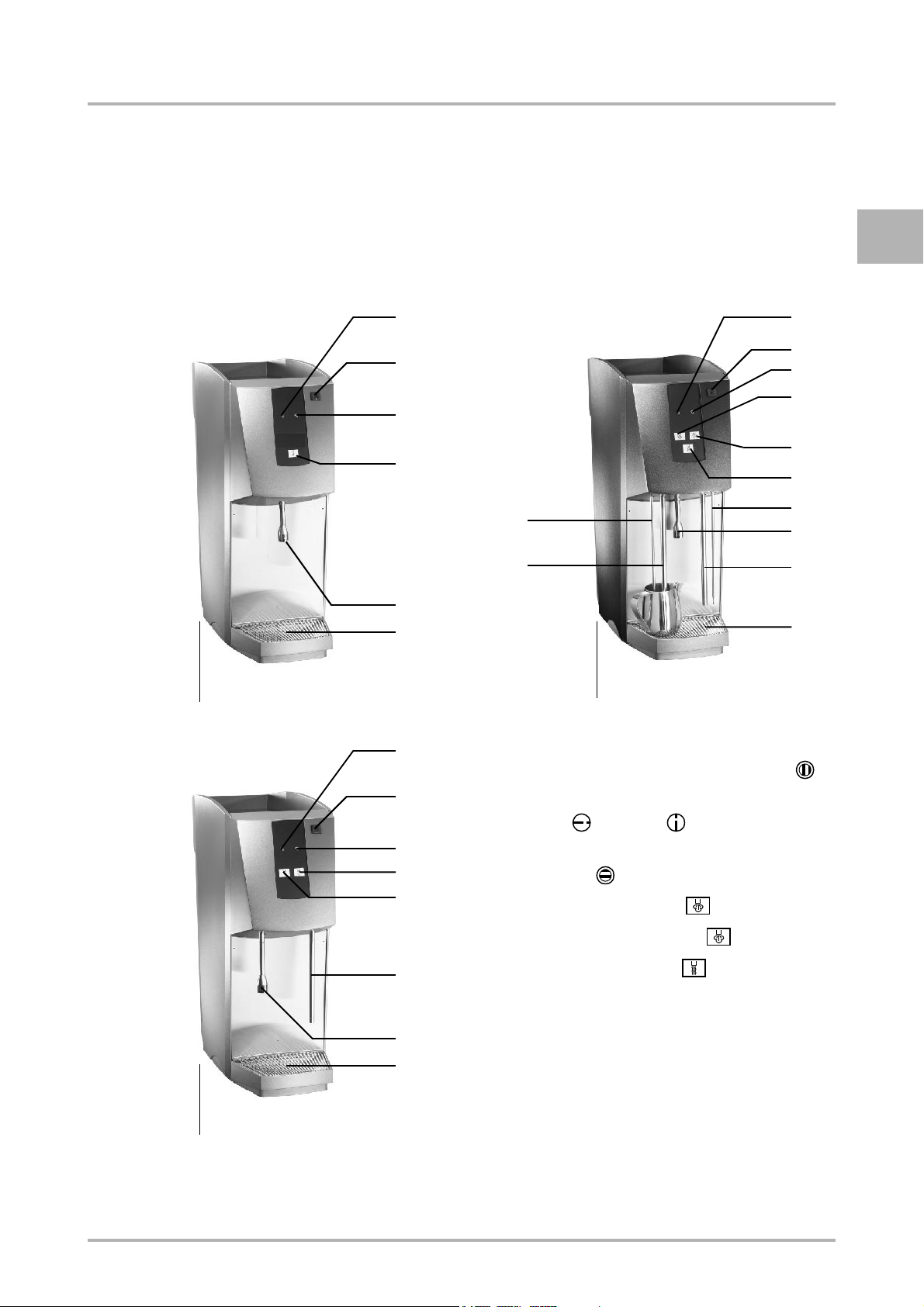
1.1.1 External parts
DESCRIPTION
E
«Type: c5-2 self»
1
2
3
5
6B
8B
7
9
«Type: c5-2C»
1
1 Operating status indicator Red [ ]
1
2
3
4A
4B
5
6A
7
8A
9
«Type: c5-2»
2
3
4B
5
8A
7
9
2 Key-operated switch (power switch)
ON [ ], OFF [ ]
3 Operating status indicator
Green [ ]
4A Steam button left [ ]
4B Steam button rights [ ]
5 Hot water button [ ]
6A Optional: temperature probe right
6B Optional: temperature probe left
7 Hot water outlet
8A Steam outlet right
8B Steam outlet left
9 Drip grille
OI c5-2 eng V1 / 08.12.2004 1-1 © Cafina / Melitta

DESCRIPTION
E
1.2 Mode of operation
1.2.1 c5-2 boiler element
The c5-2 boiler element is an autonomous
hot water/steam module with a large-volume boiler, enabling a high throughput of
beverages.
The c5-2 boiler element is normally connected directly to the water mains, but it
can also be operated with canisters.
1.2.2 "Temperature probe" option
In combination with an additionally installed
temperature probe, the final temperature
of the medium to be heated by the c5-2 /
c5-2C can be monitored.
Once the final temperature is achieved, the
supply of steam is automatically stopped.
1.3 Technical data
1.3.1 Boiler element types
n Self-service version (c5-2 self)
1 hot water outlet (fixed)
n Standard version (c5-2)
1 steam outlet (movable)
1 hot water outlet (movable)
"Temperature probe" option (movable)
n Advanced design (c5-2C)
2 steam outlets (movable)
1 hot water outlet (fixed)
"Temperature probes" option
(movable)
© Cafina / Melitta 1-2 OI c5-2 eng V1 / 08.12.2004
DESCRIPTION
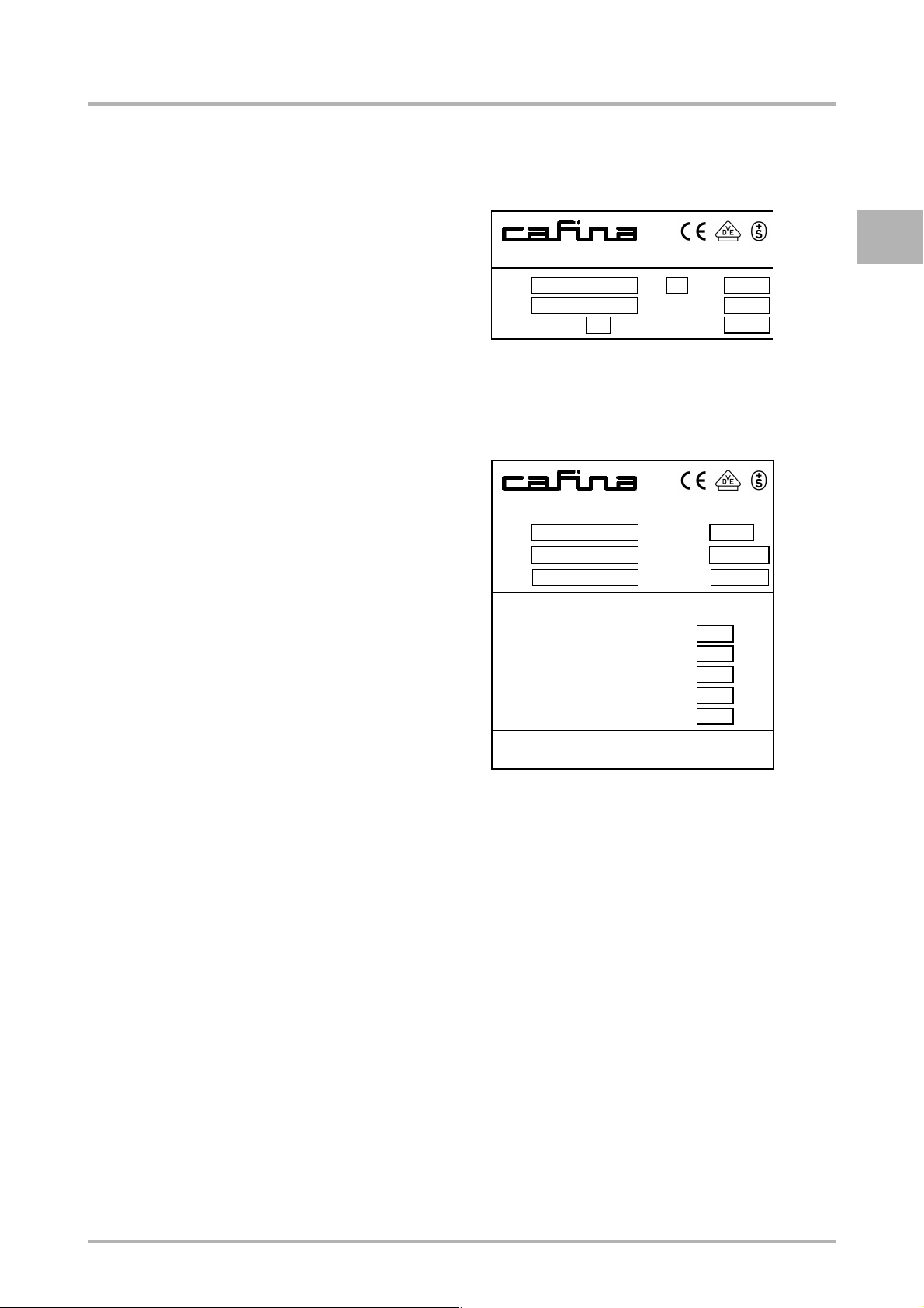
1.3.2 Machine identification
Position of identification plate:
• Switzerland, exports (e.g. EU, USA):
In two places ...
Inside at the top of the back of the machine
Outside, underneath the machine
1.3.2.1 Switzerland
CH-5502 HUNZENSCHWIL
V
Type
Instr. sheet
Hz
Serial-No.
Model year
1.3.2.2 Export
CH-5502 HUNZENSCHWIL
V
Type
Water lowest level
Max. temperature
Max. overpressure
Heater power
Serial-No.
W
Serial-No.
Model year
E
W
Boiler
litres
°C
bar
kW
Test overpressure and design comply with
the Ordinance on Steam Boilers
OI c5-2 eng V1 / 08.12.2004 1-3 © Cafina / Melitta

DESCRIPTION
1.3.3 Characteristics
E
Version c5-2 c5-2 c5-2 c5-2 c5-2 (USA)
Mains power supply [ V ] 1N AC
230
Heater element [ kW ] 3.4 4.0 6.0 3.78 4.92
Fuse protection [ A ] 16 16 16 20 30
Power consumption [ kW ] 3.45 4.05 6.05 3.83 4.97
"Pressureless" power consumption
(= built-in water pump) [ kW ]
Boiler capacity [ litres ] 7.7 7.7 7.7 7.7 7.7
Hot water throughput [ litres/h ] 30 36 50 34 44
Dimensions (W x H x D) [ mm ] 250 x 680 x 600
Empty weight [ kg ] 27.5 27.5 27.5 27.5 31.5
"Pressureless" empty weight
(= built-in water pump) [ kg ]
Fresh water connection (by the customer) R 3/8" A ; 2-4 bar
Waste water connection (by the customer) 2“
Fresh water canister (optional) [ litres ] 20
Waste water canister (optional) [ litres ] 10
3.57 4.17 6.17 3.95 5.09
32 32 32 32 36
3N AC
400
3N AC
400
3 AC
200
2 AC
208
Raised feet (optional) [ mm ] 25.4 (1“) / 50.8 (2“) / 76.2 (3“) / 101.6 (4“)
1.3.4 Environmental conditions
1.3.4.1 Temperature and humidity
n Operating and storage temperatures:
min. + 5 °C
max. + 30 °C
n Operating and storage humidity:
max. 80 %
1.3.4.2 Space requirements
n Minimum space required for operation:
Sufficient space must be kept clear around the c5-2 boiler element so as to ensure that
there is no danger while drinks are being prepared.
© Cafina / Melitta 1-4 OI c5-2 eng V1 / 08.12.2004
SAFETY INSTRUCTIONS
2 Safety instructions
2.1 Warnings
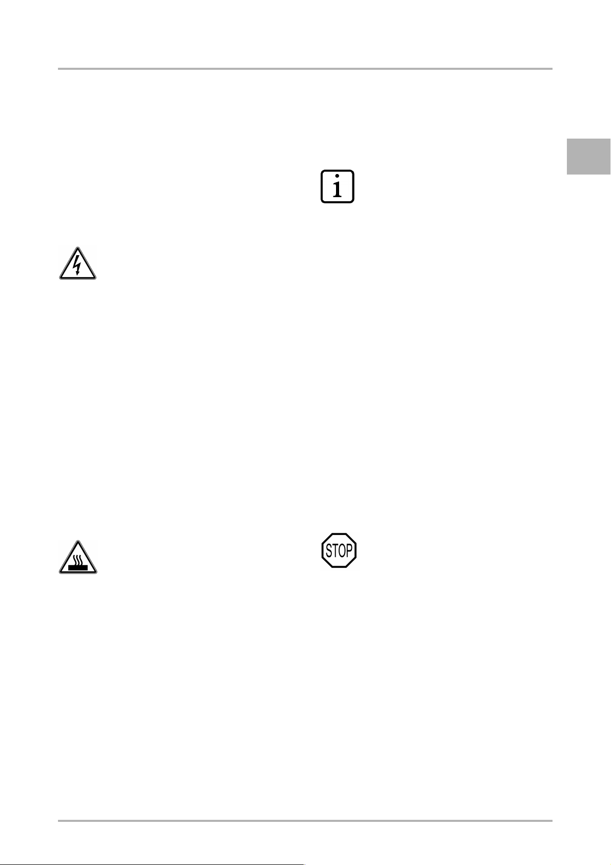
2.1.1 Warning symbols used (depending on nationality)
The following warning symbols can be affixed.
Low voltage
• Warning of dangerous elec-
trical voltage.
• Electric shocks can lead to
serious injury or death.
• Only authorised technical
personnel may perform
work on electrical installations.
• The technical safety instruc-
tions must be followed.
2.1.2 Places where warning
symbols are affixed (depending on nationality)
E
NOTE
• The equipment comes sup-
plied with warning symbols
(stickers) affixed wherever
appropriate.
• If any of the warning sym-
bols should fall off during
operation or following cleaning work, the operator must
stick these warning symbols
back again immediately.
2.1.3 Safety information in
these Operating Instructions
• Unplug c5-2 boiler element
from the mains before carrying out any work on electrical installations.
Hot surface / hot internal components
• Warning of heat which could
lead to injury.
• Allow hot surfaces and components to cool before carrying out any work on these
component parts.
• If necessary, wear heat-resistant gloves.
In these Operating Instructions, you will
find the following three levels of safety information:
n Level 1
WARNING
• A warning refers to signifi-
cant hazards. Failure to follow the relevant safety
instruction could lead to injury or death.
OI c5-2 eng V1 / 08.12.2004 2-1 © Cafina / Melitta
SAFETY INSTRUCTIONS
E
Depending on the type of danger, instead of
STOP, one of the following symbols could
be combined with the word WARNING.
WARNING
• Warning of electric shock.
WARNING
• Warning of heat.
n Level 2
CAUTION
• The CAUTION symbol
stresses important instructions. Failure to observe
these instructions could
lead to damage to the equipment or to other material assets.
n Level 3
NOTE
• Notes contain additional in-
formation aimed at raising
the general level of safety
and at lightening the user’s
workload.
2.2 Basic safety instructions
2.2.1 Proper use
2.2.1.1 General
Proper use includes, in addition to the specific provisions set out below, observing
these Operating Instructions and complying with the supplier’s obligatory maintenance and repair instructions.
2.2.1.2 c5-2 boiler element
The c5-2 boiler element is used solely to
output hot water or steam and to heat and
froth milk.
No other use of the c5-2 boiler element will
be deemed to be proper.
© Cafina / Melitta 2-2 OI c5-2 eng V1 / 08.12.2004
2.2.2 Specific hazards and instructions
2.2.2.1 c5-2 boiler element
WARNING
• Hot air comes out from the
bottom of the steam outlet.
There is a danger of scalding.
• The bottom of the steam
outlet is hot after it has been
giving off steam. There is a
danger of burns.
• Hot liquid comes out from
the bottom of the hot water
outlet. There is a danger of
scalding.
• The bottom of the hot water
outlet is hot after it has been
dispensing liquid. There is a
danger of burns.
WARNING
• Never interfere with the
electricity supply connection
or modify it. This could result
in fatal injury.
• Never remove the screw-
mounted covers. There is a
danger of fatal injury upon
contact with live components.
SAFETY INSTRUCTIONS
CAUTION
• Never interfere with the wa-
ter mains connection or
modify it. There is a danger
of flooding.
• Only operate the c5-2 boiler
element in covered locations, avoid places where
there is a risk of water
splash. There is a risk of
damage.
• Never spray the c5-2 boiler
element with a water hose
during cleaning. There is a
risk of damage.
• Never lift the c5-2 boiler element by the drip tray.
• If the internal relief pressure
valve is actuated due to improper increase of pressure,
switch the c5-2 boiler element off immediately. Secure the c5-2 boiler element
against unintentional
switching on and report to
Customer Support.
• The c5-2 boiler element
must be disconnected from
the water supply after it has
been switched off, e.g. for
the overnight period of inactivity, i.e. it is imperative that
the tap is closed.
E
OI c5-2 eng V1 / 08.12.2004 2-3 © Cafina / Melitta
SAFETY INSTRUCTIONS
2.2.3 Personal safety
E
NOTE
• Regardless of type configu-
ration, the c5-2 boiler element should not be used in
large kitchens.
• Electrical equipment which
does not have adequate
electro-magnetic protection
should not be operated
close to the c5-2 boiler element.
• The drip tray serves solely
to collect drip water. It must
not be used as a sink.
• Ideally, do not leave the key
in the key-operated switch.
WARNING
If handled improperly, the c5-2
boiler element could cause serious or fatal injury.
Anyone using and maintaining
the c5-2 boiler element must be
trained in the correct handling of
the c5-2 boiler element and
must have read and understood
the safety instructions in these
Operating Instructions before
starting to use or maintain the
c5-2 boiler element.
WARNING
Never operate the c5-2 boiler element in a damaged condition.
WARNING
Never modify or remove any
safety mechanisms.
Do not disable any safety mechanisms by modifying the c5-2
boiler element.
If there are any warning symbols
affixed to the c5-2 boiler element
(dependent on nationality), never remove these. Replace any
lost or defective warnings symbols immediately.
Report any irregularities to your
superior immediately, especially
if they affect safety.
© Cafina / Melitta 2-4 OI c5-2 eng V1 / 08.12.2004
SAFETY INSTRUCTIONS
2.3 Safety mechanisms
As well as the warning symbols (dependent
on nationality) affixed to the c5-2 boiler element, the c5-2 boiler element also has several active safety mechanisms.
2.3.1 Power switch
- c5-2 boiler element key-operated
switch
- Black grip protection
2.4 Authorised persons
2.4.1 General
Only persons who are authorised to do so
may work on or with the c5-2 boiler element.
A person is deemed to be authorised if he/
she satisfies the minimum training and
knowledge requirements listed in this section and has been assigned a fixed area of
responsibility.
2.4.2 Areas of responsibility of personnel
2.4.2.1 Operator
As the most senior person from the legal
point of view, the operator is responsible for
the proper use of the c5-2 boiler element
and for the training and deployment of authorised personnel.
E
2.3.2 Relief pressure valve
The c5-2 boiler element is fitted with an internal relief pressure valve which monitors
the boiler pressure.
He records the competencies and of authorised persons, including whether they have
the authority to give orders, for his business.
His tasks include the following:
- He sets or resets the c5-2 boiler ele-
ment to the beverages that are currently to be dispensed, if he wishes to
dispense different beverages than
those that the supplier configured upon
delivery or installation of the c5-2 boiler
element.
OI c5-2 eng V1 / 08.12.2004 2-5 © Cafina / Melitta

SAFETY INSTRUCTIONS
E
2.4.2.2 User
He is responsible for the following tasks:
- He starts up the c5-2 boiler element and
monitors it.
- He adjusts the c5-2 boiler element to
the beverages currently to be dispensed.
- He sets the c5-2 boiler element to the
products to be processed.
- He cleans and services the c5-2 boiler
element in accordance with the work
described in chapters «6 Maintenance,
6 - 1» and «7 Troubleshooting, 7 - 1».
- He pinpoints problems and organises
problem rectification.
2.4.2.3 Maintenance personnel (ser-
vice technician)
2.4.3.2 User
This is a person who has been instructed in
how to use the c5-2 boiler element and is
aware of the hazards that exist.
2.4.3.3 Maintenance personnel (service technician)
These are people who have completed specialist vocational training, are familiar with
maintenance of the c5-2 boiler element and
through their work they have acquired the
skills needed.
Maintenance work on the mechanical and
electrical aspects of the c5-2 boiler element
may only be carried out by Customer Support.
2.5 Maintenance duty
He is responsible for the following tasks:
- He maintains and repairs the c5-2
boiler element in accordance with
the work described in chapters
«6 Maintenance, 6 - 1» and «7 Troubleshooting, 7 - 1».
- He takes the c5-2 boiler element apart,
stores it and disposes of it.
2.4.3 Minimum training and
qualifications of
authorised personnel
2.4.3.1 Operator
- He has a commercial background and
performs a managerial function.
- He has specialist experience in risk assessment and staff management.
- He has read and understood chapter
«2 Safety instructions, 2 - 1».
The operator has an obligation to maintain
and clean the c5-w boiler element at regular
intervals.
- To operate the c5-2 boiler element only
in a fully operational and undamaged
condition.
- To use only OEM consumables and
spare parts.
- To test the security mechanisms to
ensure that they are working properly
following any maintenance or repair
work (see section «2.3 Safety mechanisms, 2 - 5»).
2.6 Availability of these
Operational Instructions
A copy of these Operational Instructions in
the vicinity of the c5-2 boiler element must
be available to staff using the equipment at
all times.
© Cafina / Melitta 2-6 OI c5-2 eng V1 / 08.12.2004

CONTROLS AND INDICATORS
3 Controls and indi-
cators
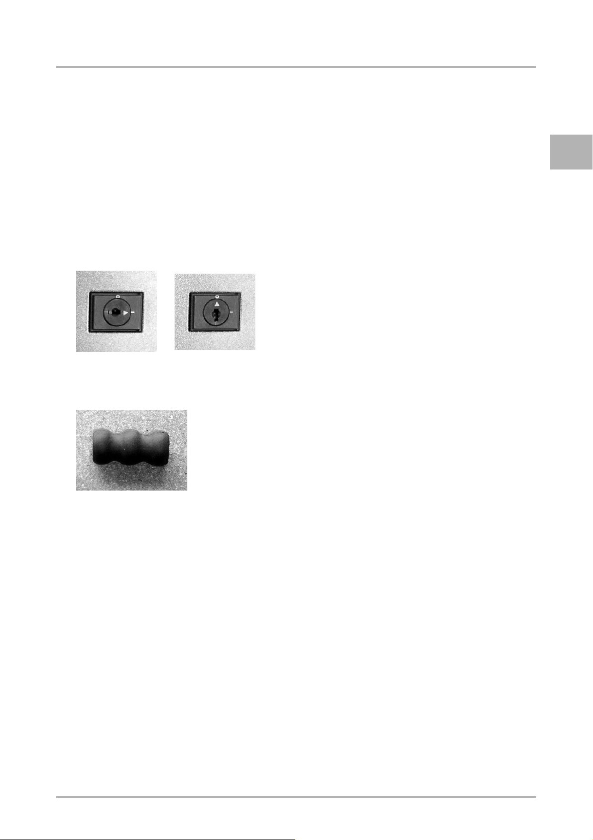
3.1 Key-operated switch
n Power switch
ON OFF
3.2 Pushbuttons
The piezo-pushbuttons are sealed, resistant to wear and respond to the application
of pressure, preferably in the centre.
3.3 Indicator lamps
n Operating status indicator Green
E
n Operating status indicator Red
n Hot water button
n Steam button
3.4 Grip elements
n Grip protection
3.5 Covers
n Drip grille
OI c5-2 eng V1 / 08.12.2004 3-1 © Cafina / Melitta

E
CONTROLS AND INDICATORS
3.6 Operating modes
Operating mode Description
In operation (free of faults,
power supply switched on)
In this condition, the c5-2 boiler element is connected to the power supply and water mains or to the canisters.
Key-operated switch "ON"
Out of service
(power supply switched off)
Key-operated switch "OFF"
In operation (with fault,
power supply switched on)
Operating status indicator Red
(flashing at regular intervals)
In operation (Programming mode,
power supply switched on)
There are no restrictions on the dispensing of beverages.
In this condition the c5-2 boiler element is disconnected from the power
supply and water mains but is still connected to the canisters.
It is not possible to dispense any beverages.
In this condition, the c5-2 boiler element is connected to the power supply and water mains or to the canisters.
There may be restrictions on the dispensing of beverages.
In the "Programming" state, the c5-2 boiler element is connected to the
power supply and water mains or to the canisters.
Operating status indicator Red
(flashing rapidly)
It is not possible to dispense any beverages.
© Cafina / Melitta 3-2 OI c5-2 eng V1 / 08.12.2004

INITIAL START-UP
4 Initial start-up
4.1 Normal initial start-up
Normal initial start-up assumes that the
c5-2 boiler element is connected to the
mains power supply.
Once the water connection has been
checked, the c5-2 boiler element can be
switched on.
4.2 Return to service after the machine has been out of service for a limited time
Initial start-up after the machine has been
out of service for a limited time assumes
that the c5-2 boiler element will normally
have been disconnected from the mains.
4.3 Return to service after a fault
Normal initial start-up after a fault assumes
that the c5-2 boiler element has not been
disconnected from the mains.
Before the c5-2 boiler element can be
operational again, the fault must have
been cleared in accordance with chapter
«7 Troubleshooting, 7 - 1».
E
Once the water connection has been
checked and the c5-2 boiler element has
been plugged in to the mains, it can be
switched on.
OI c5-2 eng V1 / 08.12.2004 4-1 © Cafina / Melitta

E
INITIAL START-UP
© Cafina / Melitta 4-2 OI c5-2 eng V1 / 08.12.2004

OPERATION
5 Operation
5.1 Power supply connection
Connection to the power supply is a matter
for the installation company and is taken for
granted below.
The equipment is connected to the power
supply either via a mains plug or a permanent connection.
5.2 Water connection
Connection to the water mains is a matter
for the installation company and is taken for
granted below.
CAUTION
• Combining a permanent
connection to the mains water supply and the use of a
waste water canister is not
recommended.
5.2.1 Water intake
The c5-2 boiler element is supplied with
water from ...
n ... the mains water supply, with perma-
nent connection to the pipe system
or
n ... from a fresh water canister with de-
tachable hose coupling.
5.2.2 Water drainage
Water is drained from the c5-2 boiler element ...
n ... into the waste water system, with
permanent connection to the pipe system
or
n ... into a waste water canister fitted with
a perforated cap.
E
• The use of a waste water
canister can cause flooding.
• Ideally, "permanent connec-
tion to permanent connection" should be the
operating mode.
OI c5-2 eng V1 / 08.12.2004 5-1 © Cafina / Melitta

OPERATION
E
5.3 Switching on and off
Switching on
1. Make sure that the c5-2 boiler element
has a water supply:
4 Turn on the tap.
2. Switch the c5-2 boiler element on by
pressing the key-operated switch
(power switch):
4 Key-operated switch "ON"
4 The operating status indicator
Green will be permanently illuminated.
4 The operating status indicator Red
lights up briefly (lamp check).
5.4 Dispensing beverages and handling
5.4.1 Drawing hot water
CAUTION
• Water outlet is hot.
• Danger of burns and scald-
ing.
• Only touch hot water outlet
by the black grip protection.
1. To the extent that it can be moved,
align hot water outlet vertically.
2. Place receptacle under hot water out-
let.
3. Press hot water button [ ].
The preprogrammed volume of hot water will be dispensed.
4 The c5-2 boiler element heats up to
operating temperature, following
which it is ready for operation.
Switching off
1. Switch the c5-2 boiler element off by
pressing the key-operated switch
(power switch):
4 Key-operated switch "OFF"
4 The operating status indicator
Green slowly darkens.
2. Disconnect the water supply to the
c5-2 boiler element:
4 Turn off the tap.
© Cafina / Melitta 5-2 OI c5-2 eng V1 / 08.12.2004

OPERATION
5.4.2 Heating milk (manually)
CAUTION
• Steam outlet is hot.
• Danger of burns and scald-
ing.
• Only touch hot steam outlet
by the black grip protection.
1. Align steam outlet vertically.
2. Press steam button [ ] twice to al-
low condensed water to run out of the
steamer outlet into the drip tray, following which only steam should come out
of the steamer outlet.
3. Rotate the steam outlet forwards and
dip it into the drink that is to be heated.
With larger receptacles, move the
steam outlet together with the receptacle towards the c5-2 boiler element and
then place the receptacle on the drip
grille.
4. Press steam button [ ] and wait un-
til the drink has reached the desired
temperature.
5. To terminate the operation, press
steam button [ ].
6. Pull receptacle forwards and put aside.
7. Wipe steam outlet clean with a moist
cloth.
8. Align steam outlet vertically.
9. Press steam button [ ] twice so as
to allow the residual fluid that is still in
the steam outlet to run off into the drip
tray.
5.4.3 Heating milk (automatically)
CAUTION
• Steam outlet is hot.
• Danger of burns and scald-
ing.
• Only touch hot steam outlet
by the black grip protection.
• Only move steamer outlet
temperature probe unit by
the steam outlet.
1. The steam outlet and the temperature
probe are mechanically linked. Align
steam outlet temperature probe unit by
moving the steam outlet vertically.
2. Press steam button [ ] twice to al-
low condensed water to run out of the
steamer outlet into the drip tray, following which only steam should come out
of the steamer outlet.
3. Rotate the steam outlet temperature
probe unit forwards and dip it into the
drink that is to be heated.
With larger receptacles, move the
steam outlet temperature unit together
with the receptacle towards the c5-2
boiler element and then place the receptacle on the drip grille.
4. Press steam button [ ] and wait un-
til the operation automatically finishes.
5. Pull receptacle forwards and put aside.
6. Wipe steam outlet and temperature
probe clean with a moist cloth.
7. Align steam outlet temperature probe
unit vertically.
8. Press steam button [ ] twice so as
to allow the residual fluid that is still in
the steam outlet to run off into the drip
tray.
E
OI c5-2 eng V1 / 08.12.2004 5-3 © Cafina / Melitta

OPERATION
E
5.4.4 Frothing milk
CAUTION
• Beware hot steam outlet
and/or splash from hot milk.
• Danger of burns and scalding.
• Only touch hot steam outlet
by the black grip protection.
Observe distance between
end of steam nozzle and the
surface of the liquid.
NOTE
• If the c5-2 boiler element is
fitted with the "Temperature
probe" option, then the
steam outlet temperature
probe unit must only be
moved by the steam outlet.
• If the c5-2 boiler element
is fitted with the "Temperature probe" option, it is only
possible to froth milk if the
depth to which the temperature probe is plunged was
specifically set by Customer
Support on the occasion of
first-time installation.
1. Align steam outlet vertically.
2. Press steam button [ ] twice to al-
low condensed water to run out of the
steamer outlet into the drip tray, following which only steam should come out
of the steamer outlet.
3. Rotate steam outlet forwards and dip
the end of the steam nozzle into the
drink to be frothed right down to the
bottom of the receptacle.
4. Press steam button [ ].
Then lower the receptacle so that the
end of the steam nozzle is just above
the surface of the liquid.
During the frothing operation, watch
the formation of froth and continually
adjust the distance between the end of
the steam nozzle and the surface of the
liquid (this will differ according to the
physical properties of the steam nozzle).
5. When the desired degree of froth has
been achieved, press the steam button
[ ] to terminate the operation.
6. Pull receptacle forwards and put aside.
7. Wipe steam outlet (temperature probe)
clean with a moist cloth.
8. Align steam outlet vertically.
9. Press steam button [ ] twice so as
to allow the residual fluid that is still in
the steam outlet to run off into the drip
tray.
© Cafina / Melitta 5-4 OI c5-2 eng V1 / 08.12.2004

OPERATION
5.4.5 Routine work
5.4.5.1 Cleaning the drip tray
The drip grille and drip tray must be
cleaned at regular intervals.
CAUTION
• Never lift the c5-2 boiler ele-
ment by the drip tray.
1. Press the drip grille at the back right or
back left corner downwards a little.
2. Remove drip grille and clean.
3. Clean drip tray and clean out the drain
holes if they are blocked.
4. Place the drip grille in the correct position on the drip tray, i.e. with the transverse rods underneath.
5.5 System work
5.5.1 Control panel and button layout
In Programming mode, the control buttons
work as follows:
[ ] "Final milk temperature" function
[ ] "Hot water quantity" function
[ ] Operating status indicator Green
[ ] Operating status indicator Red
and Programming mode
5.5.2 Programming
It is essential to stick to the sequence of operating steps for successful programming.
E
OI c5-2 eng V1 / 08.12.2004 5-5 © Cafina / Melitta

OPERATION
E
5.5.2.1 Hot water quantity
CAUTION
• Water outlet is hot.
• Danger of burns and scald-
ing.
• Only touch hot water outlet
by the black grip protection.
1. Switch on c5-2 boiler element [ ].
Wait until the boiler has heated up.
2. To the extent that it can be moved,
align hot water outlet vertically.
3. Place receptacle under hot water outlet.
4. Switch off c5-2 boiler element [ ].
Wait until the operating status indicator
Green [ ] has gone out totally.
5. Switch on c5-2 boiler element [ ]
again.
6. While the operating status indicator
Red [ ] lights up for approx. 2 seconds, press any button hard three
times in quick succession.
The operating status indicator Red
[ ] will flash rapidly, indicating that
the machine is in Programming mode.
7. Press hot water button [ ], and al-
low hot water to keep flowing into the
receptacle until the desired quantity of
hot water has been reached.
8. To terminate the dispensing of hot water, press steam button [ ].
NOTE
• The hot water dispensing
operation can last a maximum of 50 seconds. If the
operation is not stopped within this time, then
"50 sec." is automatically
stored as the outflow time.
The operating status indicator Red
[ ] goes dark and the hot water dispensing volume and outflow time are
stored.
9. Press the hot water button [ ] so
that the programmed quantity of hot
water can be dispensed.
NOTE
• The hot water dispensing
volume can vary slightly due
to fluctuations in the mains
water pressure or the boiler
pressure.
© Cafina / Melitta 5-6 OI c5-2 eng V1 / 08.12.2004

5.5.2.2 Final milk temperature
OPERATION
NOTE
• The final milk temperature
can only be programmed if
your c5-2 boiler element has
the "Temperature probe"
option!
• If the c5-2 boiler element is
fitted with two "Temperature
probe" options (right and
left), the final milk temperature can be separately programmed for each side.
• For each temperature
probe, the final milk temperature can be programmed
within the limits 55 °C and
80 °C. If the temperature of
the liquid is outside the limits
while the program is running, the operating status indicator Red [ ] flashes
four times, repeated periodically.
CAUTION
• Steam outlet is hot.
• Danger of burns and scald-
ing.
• Only touch hot steam outlet
by the black grip protection.
1. Switch on c5-2 boiler element [ ].
Wait until the boiler has heated up.
2. Rotate steam outlet and temperature
probe forwards and then dip into the
liquid to be heated: approx. 1 litre of
water.
Move steam outlet and temperature
probe together with the receptacle towards the c5-2 boiler element and then
place the receptacle on the drip grille.
NOTE
• Ideally, place a thermometer
in the liquid.
E
• The temperature is recorded
via the submerged temperature probes, with a slight
time delay. As a result, small
volumes of liquid could be
heated slightly higher and
large volumes slightly lower
(200 ml with approx. + 2 °C,
1 litre with approx. - 2 °C).
This anomaly can be compensated through appropriate warming of the
calibration liquid.
3. Press steam button [ ] and wait un-
til the operation automatically finishes.
Repeat this process until the liquid has
reached the desired temperature.
OI c5-2 eng V1 / 08.12.2004 5-7 © Cafina / Melitta

E
OPERATION
4. Switch off c5-2 boiler element [ ].
Wait until the operating status indicator
Green [ ] has gone out totally.
5. Switch on c5-2 boiler element [ ]
again.
6. While the operating status indicator Red [ ] lights up for approx.
2 seconds, press any button hard
three times in quick succession.
The operating status indicator Red
[ ] will flash rapidly, indicating that
the machine is in Programming mode.
7. Press steam button [ ].
The operating status indicator Red
[ ] will go out.
The final liquid temperature has now
been stored.
8. If necessary, go through the heating
operation for both a small quantity
of milk and a large quantity, following the procedure described in section «5.4.3 Heating milk (automatically), 5 - 3».
NOTE
• If necessary, check the final
liquid temperature using a
thermometer.
© Cafina / Melitta 5-8 OI c5-2 eng V1 / 08.12.2004

MAINTENANCE
6 Maintenance
This chapter deals exclusively with preventive maintenance of the c5-2 boiler element. In case of problems, please consult chapter «7 Troubleshooting, 7 - 1».
6.1 Maintenance schedule
6.1.1 Intervals
6.1.1.1 Cleaning intervals
Cleaning area Daily Weekly Monthly
E
Outside of c5-2 boiler element
(Stainless steel surface: chrome cleaner spray can order no. 2150024)
Control buttons
Operating status indicators
Steam outlets
Hot water outlets
Temperature probes
Drip grille
Drip tray
6.1.1.2 Intervals between services
NOTE
• The equipment must be serviced once a year, including a check of all safety
mechanisms.
n
n
n
n
n
n
n
n
OI c5-2 eng V1 / 08.12.2004 6-1 © Cafina / Melitta

E
MAINTENANCE
6.2 Periodic checks
Product dispensed Daily Weekly Monthly
Steam nozzles (check for
clogging, incrustation, deposits)
n
Hot water outlet
(check for clogging, lime)
If the equipment is used only
to dispense steam, then at
least one litre of hot water
should be passed through it
regularly (as a precaution
against the formation of
deposits)
6.3 Cleaning
6.3.1 Cleaning work
CAUTION
• Only use non-corrosive, non-abrasive household cleaners.
• Only use non-abrasive cloths.
n
n
• Use standard (rapid-action) decalcifying agent exclusively for the unscrewed
hot water outlet (filter use).
6.4 "Operator" maintenance log
The service technician from Customer Support maintains the maintenance log for the installation and subsequent maintenance work.
For this purpose he enters the necessary data into the table cells in chapter
«12 "Service Technician" maintenance log, 12 - 1».
© Cafina / Melitta 6-2 OI c5-2 eng V1 / 08.12.2004

TROUBLESHOOTING
7 Troubleshooting
7.1 Checklist for fault diagnosis and troubleshooting
7.1.1 Troubleshooting of specific conditions
Fault Cause of fault Troubleshooting measure(s)
E
c5-2 boiler element
does not respond
(not working)
Operating status indicator
Green [ ] does not light up.
No steam output, but
cold water is coming out.
The machine will not
produce any hot water.
Loud hissing noise is
audible and steam is
coming out of all the joints.
No electrical supply
voltage present.
Boiler temperature
too low.
Boiler:
water level too low.
Tap is turned off.
Relief pressure valve has
been activated due to
rise in pressure / temperature beyond permissible
limits
Switch c5-2 boiler element off
and then on again.
Check key-operated switch.
Check fuses in the electrical
mains connection.
Switch boiler element off and
then on again. Wait until the
boiler has heated up.
If the c5-2 boiler element is not
working normally 15 minutes
after switching on, switch off
the c5-2 boiler element and
notify Customer Support.
Turn the tap full on.
Notify Customer Support.
Switch off the c5-2 boiler element immediately and notify
Customer Support.
Ensure that the c5-2 boiler element cannot be unintentionally switched on.
OI c5-2 eng V1 / 08.12.2004 7-1 © Cafina / Melitta

E
TROUBLESHOOTING
7.1.2 Troubleshooting on the basis of the LED light intervals
During operation, the control system monitors the operating status continually. Any faults are
indicated by the operating status indicator Red [ ]. In case of malfunction, the user can
intervene and attempt to troubleshoot the problem in accordance with the procedures described in this chapter. Faults are indicated by the operating status indicator Red [ ]
(periodically recurring): flashing interspersed with darkness.
Flashing of operating
status indicator Red [ ]
Only applicable if the
"Temperature probe 1"
option is installed.
Only applicable if the
"Temperature probe 2"
option is installed.
Cause of fault Troubleshooting measure(s)
Temperature probe 1
(right-hand side) is faulty,
control system cannot
measure temperature.
Temperature probe 2
(left-hand side) is faulty,
control system cannot
measure temperature.
Boiler:
water level too low.
Manual heating of milk is not
possible. For safety reasons,
steam cannot be output for
more than ten seconds.
Notify Customer Support.
Manual heating of milk is not
possible. For safety reasons,
steam cannot be output for
more than ten seconds.
Notify Customer Support.
Turn the tap full on.
Switch c5-2 boiler element off
and then on again.
Dispensing of steam is not
possible, but should be restricted to a minimum so as to
avoid overheating the boiler.
Notify Customer Support.
Programming: incorrect sequence or sequence not followed consistently during
programming.
Temperature of "calibration
liquid" is below 55°C or
above 80°C.
© Cafina / Melitta 7-2 OI c5-2 eng V1 / 08.12.2004
Perform correct programming.
Use correctly warmed up "calibration liquid".

TAKING OUT OF SERVICE AND STORAGE
8 Taking out of
service and storage
8.1 Taking out of service for a limited time / taking out of service for good
If the c5-2 boiler element is to be taken out
of service for only a limited time (over an
extended period) and also when it is taken
out of service for good, the c5-2 boiler element must be disconnected from the power
supply.
All the components must be cleaned thoroughly.
If the c5-2 boiler element is to be out of service for an extended period, to avoid (frost)
damage, it should be expertly drained by
Customer Support.
8.2 Storage for a limited period / permanent storage
E
Whether the c5-2 boiler element is to be
taken out of service for a limited period or
for good, it is essential that this is done in
the proper fashion - see requirements on
the left.
When storing the equipment, the requirements specified in section «1.3.4 Environmental conditions, 1 - 4» must be observed.
OI c5-2 eng V1 / 08.12.2004 8-1 © Cafina / Melitta

E
TAKING OUT OF SERVICE AND STORAGE
© Cafina / Melitta 8-2 OI c5-2 eng V1 / 08.12.2004

PACKING AND TRANSPORTATION
9 Packing and
transportation
WARNING
• Only persons with experi-
ence of haulage and transportation are authorised to
pack and transport the c5-2
boiler element.
• The requirements set out in
chapter «2 Safety instructions, 2 - 1» must be strictly
observed!
CAUTION
• When securing the c5-2
boiler element (... in the original packaging) on the transport base, take care not to
cause any chafe marks.
When packing and transporting the equipment, the following requirements must be
observed:
E
1. Disconnect c5-2 boiler element from
the power and water mains.
2. Empty hoses and drain. This is a matter
for Customer Support.
3. Clean c5-2 boiler element.
4. If possible, pack c5-2 boiler element in
the original packaging.
5. Place the c5-2 boiler element (... in the
original packaging) on a suitable transport base in an upright position and attach to the transport base.
OI c5-2 eng V1 / 08.12.2004 9-1 © Cafina / Melitta

E
PACKING AND TRANSPORTATION
© Cafina / Melitta 9-2 OI c5-2 eng V1 / 08.12.2004

DISPOSAL
10 Disposal
WARNING
• Disassembly and disposal
of the c5-2 boiler element
may only be carried out by
persons who satisfy the necessary qualification and
training requirements.
• The requirements set out in
chapter «2 Safety instructions, 2 - 1» must be strictly
observed!
NOTE
The following requirements must be observed in the case of disposal:
1. Disconnect c5-2 boiler element from
the power and water mains.
2. Empty hoses and drain.
3. Take c5-2 boiler element apart.
4. Recycle individual parts according to
material type.
5. Dispose of non-recyclable materials
according to type.
E
• Information on disposal or-
ganisations and collection
points can be obtained from
your local administrative authority.
• During disposal, it is necessary in any case to comply
with the pertinent national
and regional laws and directives.
• The c5-2 boiler element
does not contain any materials whose disposal requires
special approval.
OI c5-2 eng V1 / 08.12.2004 10 - 1 © Cafina / Melitta

E
DISPOSAL
© Cafina / Melitta 10 - 2 OI c5-2 eng V1 / 08.12.2004

GUARANTEE, CONSUMABLE MATERIALS, SPARE PARTS, ORDERING
11 Guarantee,
consumable
materials, spare
parts, ordering
Guarantee
This machine is guaranteed for a guarantee period
of 12 months. The guarantee period commences
the day that the equipment is installed.
During the guarantee period, any problems with materials and any defects attributable to defective design or construction will be rectified free of charge by
us or by our authorised subcontractor. It is a requirement that the machine has been used as directed
and properly handled in accordance with the pertinent sections of these Operating Instructions.
Accordingly, we shall not be held liable in the following cases:
- faults due to dirt accumulation as a result of im-
proper cleaning (e.g. blocked valves)
- faults due to calcification or other deposits dur-
ing operation with water softening equipment
(e.g. boiler, water pumps)
- faults due to mains overvoltage (e.g. blown
print circuit boards)
We accept no responsibility for damage to any
equipment that arises as a result of improper servicing and maintenance by the customer.
We accept no responsibility for any defects in our
equipment which are due to improper repairs or to
the installation of non-original spare parts.
Normal wear and tear of parts which are subject to
natural wear and tear is specifically excluded from
this guarantee.
Such parts include:
- seals
- filters
- paintwork
To make a claim under the guarantee, the defective
part must be returned to the manufacturer. The
manufacturer reserves the right to refuse a claim under guarantee after inspecting the returned part, if
one of the conditions mentioned above applies.
Acknowledgement of damage which falls within the
terms of the guarantee is only possible after a written report from the manufacturer.
Any adjustments of quality which are not carried out
due to a malfunction are excluded from the guarantee.
The fact that work is carried out during the guarantee period will not extend this period.
Consumable materials, spare parts, ordering
Normally concerns service technicians, third-party
customers and resellers:
To avoid misunderstandings over the ordering of
consumable materials or spare parts, we would ask
you to always specify the following information in
your order:
n machine ID as per type plate.
n name and, if appropriate, article number of the
consumable item or spare part.
n number of consumable materials or spare parts
required.
Equipment-specific consumable materials and
spare parts must be obtained from the customer
service address for the relevant country.
Only equipment-specific spare parts supplied by the
manufacturer may be used.
The manufacturer does not accept any liability in
cases where it turns out that non equipment-specific
spare parts from the manufacturer have been installed in the relevant machine.
E
OI c5-2 eng V1 / 08.12.2004 11 - 1 © Cafina / Melitta
GUARANTEE, CONSUMABLE MATERIALS, SPARE PARTS, ORDERING
A Adresses of service AUS Adresses of service B Serviceadressen
E
CH Adresses of service D Adresses of service
DK Serviceadresser E Servico Tecnicos F Services Techniques
FIN Huoltopisteiden osoitteita GB Customer Support addresses J Adresses of service
N Serviceadresser NL Serviceadressen RC Adresses of service
RUS Service S Serviceadresser TH Adresses of service
USA Adresses of service KR Adresses of service TW Adresses of service
A
MELITTA System Service
International GmbH
Ziegeleistrasse 31
5020 Salzburg
Tel. +43-662 / 88 28 88-33
Fax +43-662 / 88 28 88-99
CH
CAFINA AG
Römerstrasse 2
5502 Hunzenschwil
Phone +41-62 / 889 42 42
Fax +41-62 / 889 42 89
Instruktionsnummer: 17098
AUS
National Coffee
Distributors
PO Box 201
Fairy Meadow NSW 2519
Phone +61-2 / 95 71-44 44
Fax +61-2 / 42 84-60 99
D
MELITTA System Service
GmbH & Co. KG
Zechenstrasse 60
32429 Minden-Dützen
Phone +49-571 / 50 49-0
Fax +49-571 / 50 49-233
B
MELITTA System Service Benelux
Bijkantoor MELITTA Syst. Service
Brandstraat, 8
9160 Lokeren
Phone +32-9 / 331 52 30
Fax +32-9 / 331 52 35
DK N
aromateknik a/s
Industrivej 44
4000 Roskilde
Phone +45-46 / 75 33 66
Fax +45-46 / 75 38 10
E
Tecnimel Hosteleria, S.L.
Avda. Esparteros, 15
Pol. S. J. de Valderas Sanahuja
28918 Leganés (Madrid)
Phone +34-91 / 644 81 30
Fax +34-91 / 644 81 31
F
MELITTA System Service
France SA
16 Rue P.H. Spaak
Saint Thibault des Vignes
77462 LAGNY sur Marne Cedex
Phone +33-1 / 6430 32 95
Fax +33-1 / 6430 33 40
KR
Edward Keller (Korea) Ltd.
3F. Nasan Bldg. 1024
Daechi-dong
Kangnam-gu
Seoul 135-173
Phone +82-2 / 2192-9541
Fax +82-2 / 2192-9590
S
aromateknik A/S
Radiovägen 2
Box 662
13526 Tyresö
Phone +46-8 / 7 98 77 88
Fax +46-8 / 7 98 90 18
FIN
Hackman
Metos Oy AB
Ahjonkaarre
04220 Kerava
Phone +358-204 / 39 13
Fax +358-204 / 39 44 33
NL
MELLITA
System Service Benelux BV
Industriestraat 6
3371 XD HARDINXVELD
GIESSENDAM
Phone +31-18 467 / 16 60
Fax +31-18 461 / 04 14
TH
Great Earth International Co., Ltd.
5th Floor, M Thai Tower,
All Seasons Place
87 Wireless Road, Patumwan
Bangkok 10330
Phone +66-2 / 654-1118
Fax +66-2 / 654-1119
GB
M.S.S. (UK) Limited
21 Grove Park
White Waltham
Maidenhead Berkshire
SL6 3LW
Phone +44-1628 / 82 98 88
Fax +44-1628 / 82 51 11
RC
Edward Keller
21/F Southmark
11 Yip Hing St.
Wong Chuk Hang
Hongkong / China
Phone +852 / 28 95-96 20
Fax +852 / 28 95-00 39
USA
Michaelo Espresso, Inc.
3801 Stone Way N.
Seattle, WA 98 103
Phone +1-206 / 548-9000
Fax +1-206 / 695-4951
J
MELITTA Japan Ltd.
9F abc Kaikan
2-6-3, Shiba-koen, Minato-ku
Tokyo 105-0011 Japan
Phone +81-3 / 5470-2770
Fax +81-3 / 5470-2774
RUS
MELITTA Russland
Sofiskaya 14 of. 805
192236 St. Petersburg
Phone +7-812 / 3 26 65 56
Fax +7-812 / 3 26 65 57
TW
JAS Corporation
B1, No. 17, Lane 28
Sec. 1, Huan Shan Rd.,
Nei Hu Area
Taipei
Phone +886-2 / 2727-0630
Fax +886-2 / 2727-0640
© Cafina / Melitta 11 - 2 OI c5-2 eng V1 / 08.12.2004

"SERVICE TECHNICIAN" MAINTENANCE LOG
12 "Service Technician" maintenance log
Installation Serial no.:
Date: Installed water filter type:
Key:
[ A ] = Service of whole system
[ S ] = Annual check of safety mechanisms
Service Technician no.:
Water measured values
on ...
1)
... IN
Signature: GH°:
kH°:
pH:
Date: Service * Water values Notes:
[ A ] [ S ] [ F ]
Service Technician no.:
Signature: GH°:
... OUT
2)
[ F ] = Water filter replaced
* = Check applicable fields
1)
= Untreated water before the filter
2)
= Water at the beverage outlet
Water measured values
on ...
1)
... IN
kH°:
pH:
... OUT
2)
E
Date: Service * Water values Notes:
[ A ] [ S ] [ F ]
Service Technician no.:
Water measured values
on ...
1)
... IN
Signature: GH°:
kH°:
pH:
Date: Service * Water values Notes:
[ A ] [ S ] [ F ]
Service Technician no.:
Water measured values
on ...
1)
... IN
Signature: GH°:
kH°:
pH:
... OUT
... OUT
2)
2)
OI c5-2 eng V1 / 08.12.2004 12 - 1 © Cafina / Melitta

E
"SERVICE TECHNICIAN" MAINTENANCE LOG
Date: Service * Water values Notes:
[ A ] [ S ] [ F ]
Service Technician no.:
Water measured values
on ...
1)
... IN
Signature: GH°:
kH°:
pH:
Date: Service * Water values Notes:
[ A ] [ S ] [ F ]
Service Technician no.:
Water measured values
on ...
1)
... IN
... OUT
... OUT
2)
2)
Signature: GH°:
kH°:
pH:
Date: Service * Water values Notes:
[ A ] [ S ] [ F ]
Service Technician no.:
Water measured values
on ...
1)
... IN
Signature: GH°:
kH°:
pH:
Date: Service * Water values Notes:
[ A ] [ S ] [ F ]
Service Technician no.:
Water measured values
on ...
1)
... IN
Signature: GH°:
... OUT
... OUT
2)
2)
kH°:
pH:
© Cafina / Melitta 12 - 2 OI c5-2 eng V1 / 08.12.2004

"SERVICE TECHNICIAN" MAINTENANCE LOG
Date: Service * Water values Notes:
[ A ] [ S ] [ F ]
Service Technician no.:
Water measured values
on ...
1)
... IN
Signature: GH°:
kH°:
pH:
Date: Service * Water values Notes:
[ A ] [ S ] [ F ]
Service Technician no.:
Water measured values
on ...
1)
... IN
... OUT
... OUT
2)
2)
E
Signature: GH°:
kH°:
pH:
Date: Service * Water values Notes:
[ A ] [ S ] [ F ]
Service Technician no.:
Water measured values
on ...
1)
... IN
Signature: GH°:
kH°:
pH:
Date: Service * Water values Notes:
[ A ] [ S ] [ F ]
Service Technician no.:
Water measured values
on ...
1)
... IN
Signature: GH°:
... OUT
... OUT
2)
2)
kH°:
pH:
OI c5-2 eng V1 / 08.12.2004 12 - 3 © Cafina / Melitta

E
"SERVICE TECHNICIAN" MAINTENANCE LOG
Date: Service * Water values Notes:
[ A ] [ S ] [ F ]
Service Technician no.:
Water measured values
on ...
1)
... IN
Signature: GH°:
kH°:
pH:
Date: Service * Water values Notes:
[ A ] [ S ] [ F ]
Service Technician no.:
Water measured values
on ...
1)
... IN
... OUT
... OUT
2)
2)
Signature: GH°:
kH°:
pH:
Date: Service * Water values Notes:
[ A ] [ S ] [ F ]
Service Technician no.:
Water measured values
on ...
1)
... IN
Signature: GH°:
kH°:
pH:
Date: Service * Water values Notes:
[ A ] [ S ] [ F ]
Service Technician no.:
Water measured values
on ...
1)
... IN
Signature: GH°:
... OUT
... OUT
2)
2)
kH°:
pH:
© Cafina / Melitta 12 - 4 OI c5-2 eng V1 / 08.12.2004

INDEX
Page Page
B
Basic safety instructions . . . . . . . . . 2 - 2
C
Characteristics . . . . . . . . . . . . . . . . 1 - 4
Cleaning work . . . . . . . . . . . . . . . . . 6 - 2
Consumable materials . . . . . . . . . 11 - 1
Control elements . . . . . . . . . . . . . . 3 - 1
Customer Support addresses . . . . 11 - 2
D
Description . . . . . . . . . . . . . . . . . . . 1 - 1
Disposal . . . . . . . . . . . . . . . . . . . . 10 - 1
G
P
Packing . . . . . . . . . . . . . . . . . . . . . . 9 - 1
Periodic checks . . . . . . . . . . . . . . . . 6 - 2
Physical construction . . . . . . . . . . . . 1 - 1
S
Safety instructions . . . . . . . . . . . . . . 2 - 1
Safety mechanisms . . . . . . . . . . . . . 2 - 5
Service Technician
maintenance log . . . . . . . . . . . . . . . 12 - 1
Spare part . . . . . . . . . . . . . . . . . . . 11 - 1
Specific hazards
and instructions . . . . . . . . . . . . . . . . 2 - 3
Storage . . . . . . . . . . . . . . . . . . . . . . 8 - 1
E
Guarantee . . . . . . . . . . . . . . . . . . . 11 - 1
I
Indicators . . . . . . . . . . . . . . . . . . . . 3 - 1
Initial start-up . . . . . . . . . . . . . . . . . 4 - 1
M
Maintenance . . . . . . . . . . . . . . . . . . 6 - 1
Mode of operation . . . . . . . . . . . . . . 1 - 2
O
Operating modes . . . . . . . . . . . . . . 3 - 2
Operation . . . . . . . . . . . . . . . . . . . . 5 - 1
Operator maintenance log . . . . . . . 6 - 2
T
Taking out of service . . . . . . . . . . . . 8 - 1
Technical data . . . . . . . . . . . . . . . . . 1 - 2
Transportation . . . . . . . . . . . . . . . . . 9 - 1
Troubleshooting . . . . . . . . . . . . . . . . 7 - 1
W
Warnings . . . . . . . . . . . . . . . . . . . . . 2 - 1
Ordering . . . . . . . . . . . . . . . . . . . . 11 - 1
OI c5-2 eng V1 / 08.12.2004 I © Cafina / Melitta

E
INDEX
© Cafina / Melitta II OI c5-2 eng V1 / 08.12.2004
 Loading...