


STHI
INTELLIGENT
TOKEN RING STACKABLE HUB
USER’S GUIDE
CABLETRON SYSTEMS, P. O. Box 5005 Rochester, NH 03866-5005

NOTICE
NOTICE |
1 |
Cabletron Systems reserves the right to make changes in specifications and other information contained in this document without prior notice. The reader should in all cases consult Cabletron Systems to determine whether any such changes have been made.
The hardware, firmware, or software described in this manual is subject to change without notice.
IN NO EVENT SHALL CABLETRON SYSTEMS BE LIABLE FOR ANY INCIDENTAL, INDIRECT, SPECIAL, OR CONSEQUENTIAL DAMAGES WHATSOEVER (INCLUDING BUT NOT LIMITED TO LOST PROFITS) ARISING OUT OF OR RELATED TO THIS MANUAL OR THE INFORMATION CONTAINED IN IT, EVEN IF CABLETRON SYSTEMS HAS BEEN ADVISED OF, KNOWN, OR SHOULD HAVE KNOWN, THE POSSIBILITY OF SUCH DAMAGES.
© Copyright May, 1995 by: Cabletron Systems, Inc.
P.O. Box 5005, Rochester, NH 038666-5005
All Rights Reserved
Printed in the United States of America
Order Number: 9031390 May, 1995
SPECTRUM, LANVIEW, Remote LANVIEW, and HubSTACK, STH, STHI, are trademarks of Cabletron Systems, Inc.
i960 is a registered trademark of Intel Corporation.
DEC and VT100 are trademarks of Digital Equipment Corporation.
CompuServe is a registered trademark of CompuServe, Inc.
Windows is a registered trademark of Microsoft Corporation.
Printed On |
Recycled Paper |
iii

NOTICE
FCC NOTICE |
2 |
This device complies with Part 15 of the FCC rules. Operation is subject to the following two conditions: (1) this device may not cause harmful interference, and
(2) this device must accept any interference received, including interference that may cause undesired operation.
NOTE: This equipment has been tested and found to comply with the limits for a Class A digital device, pursuant to Part 15 of the FCC rules. These limits are designed to provide reasonable protection against harmful interference when the equipment is operated in a commercial environment. This equipment uses, generates, and can radiate radio frequency energy and if not installed in accordance with the operator’s manual, may cause harmful interference to radio communications. Operation of this equipment in a residential area is likely to cause interference in which case the user will be required to correct the interference at his own expense.
WARNING: Changes or modifications made to this device which are not expressly approved by the party responsible for compliance could void the user’s authority to operate the equipment.
DOC NOTICE |
3 |
This digital apparatus does not exceed the Class A limits for radio noise emissions from digital apparatus set out in the Radio Interference Regulations of the Canadian Department of Communications.
Le présent appareil numérique n’émet pas de bruits radioélectriques dépassant les limites applicables aux appareils numériques de la class A prescrites dans le Règlement sur le brouillage radioélectrique édicté par le ministère des Communications du Canada.
CABLETRON SYSTEMS, INC. |
|
PROGRAM LICENSE AGREEMENT |
4 |
IMPORTANT: Before utilizing this product, carefully read this License Agreement.
This document is an agreement between you, the end user, and Cabletron Systems, Inc. (“Cabletron”) that sets forth your rights and obligations with respect to the Cabletron software program (the “Program”) contained in this package. The Program may be contained in firmware, chips or other media. BY UTILIZING THE ENCLOSED PRODUCT, YOU ARE AGREEING TO BECOME BOUND BY THE TERMS OF THIS AGREEMENT, WHICH INCLUDES THE LICENSE AND THE LIMITATION OF WARRANTY AND DISCLAIMER OF LIABILITY. IF YOU DO NOT AGREE TO THE TERMS OF THIS AGREEMENT, PROMPTLY RETURN THE UNUSED PRODUCT TO THE PLACE OF PURCHASE FOR A FULL REFUND.
iv

NOTICE
CABLETRON SOFTWARE PROGRAM LICENSE |
5 |
1.LICENSE. You have the right to use only the one (1) copy of the Program provided in this package subject to the terms and conditions of this License Agreement.
You may not copy, reproduce or transmit any part of the Program except as permitted by the Copyright Act of the United States or as authorized in writing by Cabletron.
2.OTHER RESTRICTIONS. You may not reverse engineer, decompile, or disassemble the Program.
3.APPLICABLE LAW. This License Agreement shall be interpreted and governed under the laws and in the state and federal courts of New Hampshire. You accept the personal jurisdiction and venue of the New Hampshire courts.
EXCLUSION OF WARRANTY |
|
AND DISCLAIMER OF LIABILITY |
6 |
1.EXCLUSION OF WARRANTY. Except as may be specifically provided by Cabletron in writing, Cabletron makes no warranty, expressed or implied, concerning the Program (including Its documentation and media).
CABLETRON DISCLAIMS ALL WARRANTIES, OTHER THAN THOSE SUPPLIED TO YOU BY CABLETRON IN WRITING, EITHER EXPRESS OR IMPLIED, INCLUDING BUT NOT LIMITED TO IMPLIED WARRANTIES OF MERCHANTABLITY AND FITNESS FOR A PARTICULAR PURPOSE, WITH RESPECT TO THE PROGRAM, THE ACCOMPANYING WRITTEN MATERIALS, AND ANY ACCOMPANYING HARDWARE.
2.NO LIABILITY FOR CONSEQUENTIAL DAMAGES. IN NO EVENT SHALL CABLETRON OR ITS SUPPLIERS BE LIABLE FOR ANY DAMAGES WHATSOEVER (INCLUDING, WITHOUT LIMITATION, DAMAGES FOR LOSS OF BUSINESS, PROFITS, BUSINESS INTERRUPTION, LOSS OF BUSINESS INFORMATION, SPECIAL, INCIDENTAL, CONSEQUENTIAL, OR RELIANCE DAMAGES, OR OTHER LOSS) ARISING OUT OF THE USE OR INABILITY TO USE THIS CABLETRON PRODUCT, EVEN IF CABLETRON HAS BEEN ADVISED OF THE POSSIBILITY OF SUCH DAMAGES. BECAUSE SOME STATES DO NOT ALLOW THE EXCLUSION OR LIMITATION OF LIABILITY FOR CONSEQUENTIAL OR INCIDENTAL DAMAGES, OR ON THE DURATION OR LIMITATION OF IMPLIED WARRANTEES IN SOME INSTANCES THE ABOVE LIMITATIONS AND EXCLUSIONS MAY NOT APPLY TO YOU.
v

NOTICE
UNITED STATES GOVERNMENT |
|
RESTRICTED RIGHTS |
7 |
The enclosed product (a) was developed solely at private expense; (b) contains “restricted computer software” submitted with restricted rights in accordance with Section 52227-19 (a) through (d) of the Commercial Computer Software - Restricted Rights Clause and its successors, and (c) in all respects is proprietary data belonging to Cabletron and/or its suppliers.
For Department of Defense units, the product is licensed with “Restricted Rights” as defined in the DoD Supplement to the Federal Acquisition Regulations, Section 52.227-7013 (c) (1) (ii) and its successors, and use, duplication, disclosure by the Government is subject to restrictions as set forth in subparagraph (c) (1) (ii) of the Rights in Technical Data and Computer Software clause at 252.227-7013. Cabletron Systems, Inc., 35 Industrial Way. Rochester, New Hampshire 03866
vi

CONTENTS
CHAPTER 1 |
Introduction |
1.1 Contents of This Manual. . . . . . . . . . . . . . . . . . . . . . . . . . . 1-1 1.2 STHI Overview. . . . . . . . . . . . . . . . . . . . . . . . . . . . . . . . . . 1-1 1.2.1 LANVIEW LEDs . . . . . . . . . . . . . . . . . . . . . . . . . . 1-2 1.2.2 TCU Ports . . . . . . . . . . . . . . . . . . . . . . . . . . . . . . . . 1-3 1.2.3 RI & RO Ports. . . . . . . . . . . . . . . . . . . . . . . . . . . . . 1-4 1.2.4 Hub-By-Hub Bypass Control . . . . . . . . . . . . . . . . . 1-5 1.2.5 Automatic Beacon Recovery Process . . . . . . . . . . . 1-5 1.2.6 Support for Passive MAU Workgroups . . . . . . . . . 1-5 1.2.7 Flash Downloads. . . . . . . . . . . . . . . . . . . . . . . . . . . 1-6 1.2.8 IP Address Discovery . . . . . . . . . . . . . . . . . . . . . . . 1-6 1.2.9 Local Management . . . . . . . . . . . . . . . . . . . . . . . . . 1-8 1.2.10 Remote Network Management Capabilities . . . . . . 1-8 1.3 Related Manuals . . . . . . . . . . . . . . . . . . . . . . . . . . . . . . . . . 1-8
1.4 Getting Help . . . . . . . . . . . . . . . . . . . . . . . . . . . . . . . . . . . . 1-8
CHAPTER 2 Requirements & Specifications
2.1 General Networking Considerations. . . . . . . . . . . . . . . . . . 2-1
2.2 Operating Specifications . . . . . . . . . . . . . . . . . . . . . . . . . . . 2-3
2.2.1 Hubstack Interconnect Cables. . . . . . . . . . . . . . . . . 2-3
2.2.2 TCU and COM Ports . . . . . . . . . . . . . . . . . . . . . . . 2-3
2.2.3 Supported MIB Groups. . . . . . . . . . . . . . . . . . . . . . 2-5
2.2.4 Ring Speed . . . . . . . . . . . . . . . . . . . . . . . . . . . . . . . 2-5
2.2.5 Ring Sequence . . . . . . . . . . . . . . . . . . . . . . . . . . . . 2-6
2.2.6 Safety . . . . . . . . . . . . . . . . . . . . . . . . . . . . . . . . . . . 2-6
2.2.7 Computing Hardware . . . . . . . . . . . . . . . . . . . . . . . 2-7
2.2.8 Environmental Requirements . . . . . . . . . . . . . . . . . 2-7
2.2.9 Physical Specifications . . . . . . . . . . . . . . . . . . . . . . 2-7
CHAPTER 3 |
Installation |
3.1 Installing the STHI . . . . . . . . . . . . . . . . . . . . . . . . . . . . . . . 3-1
3.1.1 Unpacking the STHI . . . . . . . . . . . . . . . . . . . . . . . . 3-1
3.1.2 Stacking the STHI. . . . . . . . . . . . . . . . . . . . . . . . . . 3-2
3.1.3 Attaching the Strain Relief Bracket . . . . . . . . . . . . 3-2
vii

CONTENTS
3.1.4 Rack-Mounting the STHI . . . . . . . . . . . . . . . . . . . . 3-2 3.1.5 Wall-Mounting the STHI . . . . . . . . . . . . . . . . . . . . 3-3 3.1.6 Free-Standing Installations . . . . . . . . . . . . . . . . . . . 3-5 3.1.7 Connecting the STHI to the Power Source . . . . . . . 3-6 3.2 TPIM Installation . . . . . . . . . . . . . . . . . . . . . . . . . . . . . . . . 3-6
3.3 Finishing the Installation. . . . . . . . . . . . . . . . . . . . . . . . . . . 3-6
CHAPTER 4 Troubleshooting
4.1 LANVIEW LED Signals . . . . . . . . . . . . . . . . . . . . . . . . . . 4-1
4.2 Trouble Resolution . . . . . . . . . . . . . . . . . . . . . . . . . . . . . . . 4-2
4.3 The Reset Button. . . . . . . . . . . . . . . . . . . . . . . . . . . . . . . . . 4-3
4.4 NVRAM Reset Switch . . . . . . . . . . . . . . . . . . . . . . . . . . . . 4-4
CHAPTER 5 Local Management
5.1 Accessing LM . . . . . . . . . . . . . . . . . . . . . . . . . . . . . . . . . . . 5-1
5.1.1 Dumb Terminal Configuration . . . . . . . . . . . . . . . . 5-2
5.1.2 Console Cable Configuration . . . . . . . . . . . . . . . . . 5-3
5.1.3 Entering LM . . . . . . . . . . . . . . . . . . . . . . . . . . . . . . 5-3
5.2 Using LM Screens. . . . . . . . . . . . . . . . . . . . . . . . . . . . . . . . 5-4
5.2.1 Working with LM Screens . . . . . . . . . . . . . . . . . . . 5-4
5.2.2 Screen Hierarchy. . . . . . . . . . . . . . . . . . . . . . . . . . . 5-6
5.2.3 Screen Introductions . . . . . . . . . . . . . . . . . . . . . . . . 5-6
5.3 The System Level Screen . . . . . . . . . . . . . . . . . . . . . . . . . . 5-8
5.3.1 System Date and System Time . . . . . . . . . . . . . . . . 5-8
5.3.2 IP Address. . . . . . . . . . . . . . . . . . . . . . . . . . . . . . . . 5-8
5.3.3 Subnet Mask . . . . . . . . . . . . . . . . . . . . . . . . . . . . . . 5-9
5.3.4 Enable IP Address Discovery . . . . . . . . . . . . . . . . . 5-9
5.3.5 Enable Beacon Recovery . . . . . . . . . . . . . . . . . . . 5-10
5.3.6 MAC Address . . . . . . . . . . . . . . . . . . . . . . . . . . . . 5-11
5.3.7 Locally Administered Address . . . . . . . . . . . . . . . 5-11
5.4 The SNMP Community Names Screen . . . . . . . . . . . . . . 5-11
5.4.1 Community Name. . . . . . . . . . . . . . . . . . . . . . . . . 5-12
5.4.2 Access Policy . . . . . . . . . . . . . . . . . . . . . . . . . . . . 5-12
5.5 The SNMP Traps Screen . . . . . . . . . . . . . . . . . . . . . . . . . 5-13
viii

CONTENTS
5.5.1 Trap Destination . . . . . . . . . . . . . . . . . . . . . . . . . . 5-13
5.5.2 Trap Community Name . . . . . . . . . . . . . . . . . . . . 5-13
5.5.3 Enable Traps . . . . . . . . . . . . . . . . . . . . . . . . . . . . . 5-13
5.6 The Chassis Status View Screen. . . . . . . . . . . . . . . . . . . . 5-14
5.6.1 The Screen Mode Screen Command. . . . . . . . . . . 5-14
5.6.2 Multiplexer Configuration Fields . . . . . . . . . . . . . 5-15
5.6.3 Port Configuration Fields . . . . . . . . . . . . . . . . . . . 5-16
5.6.4 NEXT and PREVIOUS. . . . . . . . . . . . . . . . . . . . . 5-20
5.6.5 ENABLE ALL PORTS. . . . . . . . . . . . . . . . . . . . . 5-20
5.6.6 REFRESH . . . . . . . . . . . . . . . . . . . . . . . . . . . . . . . 5-20
5.7 The Component Status Screen . . . . . . . . . . . . . . . . . . . . . 5-20
5.8 The Device Statistics Screen. . . . . . . . . . . . . . . . . . . . . . . 5-21
5.8.1 Screen Mode . . . . . . . . . . . . . . . . . . . . . . . . . . . . . 5-22
5.8.2 REFRESH 3SEC. . . . . . . . . . . . . . . . . . . . . . . . . . 5-22
5.8.3 General Counter Fields (Group 1) . . . . . . . . . . . . 5-23
5.8.4 Ring Information Fields (Group 2) . . . . . . . . . . . . 5-23
5.8.5 Isolating Errors Fields (Group 3) . . . . . . . . . . . . . 5-25
5.8.6 Non-Isolating Errors (Group 4) . . . . . . . . . . . . . . 5-26
5.9 The SNMP Tool Screen . . . . . . . . . . . . . . . . . . . . . . . . . . 5-27
5.9.1 Community Name. . . . . . . . . . . . . . . . . . . . . . . . . 5-28
5.9.2 OID Prepend . . . . . . . . . . . . . . . . . . . . . . . . . . . . . 5-28
5.9.3 GET. . . . . . . . . . . . . . . . . . . . . . . . . . . . . . . . . . . . 5-28
5.9.4 GETNEXT . . . . . . . . . . . . . . . . . . . . . . . . . . . . . . 5-29
5.9.5 STEP . . . . . . . . . . . . . . . . . . . . . . . . . . . . . . . . . . . 5-29
5.9.6 WALK. . . . . . . . . . . . . . . . . . . . . . . . . . . . . . . . . . 5-30
5.9.7 CYCLES . . . . . . . . . . . . . . . . . . . . . . . . . . . . . . . . 5-30
5.9.8 RECALL-OID. . . . . . . . . . . . . . . . . . . . . . . . . . . . 5-30
5.9.9 SET . . . . . . . . . . . . . . . . . . . . . . . . . . . . . . . . . . . . 5-30
5.9.10 REPEAT . . . . . . . . . . . . . . . . . . . . . . . . . . . . . . . . 5-31
5.9.11 Firmware Image Downloads. . . . . . . . . . . . . . . . . 5-31
Appendix A TPIM Specifications |
|
|
A.1 |
Overview. . . . . . . . . . . . . . . . . . . . . . . . . . . . . . . . . . . . . . |
A-1 |
A.2 |
Twisted Pair TPIM Pinouts. . . . . . . . . . . . . . . . . . . . . . . . |
A-1 |
A.3 |
Fiber Optic TPIM Specifications . . . . . . . . . . . . . . . . . . . |
A-2 |
ix

CONTENTS
A.3.1 TPIM-F2 for Multimode Fiber . . . . . . . . . . . . . . . A-3 A.3.2 TPIM-F3 for Single Mode Fiber. . . . . . . . . . . . . . A-4
Appendix B Media Specifications
B.1 Unshielded Twisted Pair (UTP) . . . . . . . . . . . . . . . . . . . . .B-1
B.1.1 UTP Cable Categories. . . . . . . . . . . . . . . . . . . . . . .B-1
B.1.2 UTP Lobe Lengths . . . . . . . . . . . . . . . . . . . . . . . . .B-2
B.2 Shielded Twisted Pair (STP). . . . . . . . . . . . . . . . . . . . . . . .B-3
B.2.1 STP Cable Categories . . . . . . . . . . . . . . . . . . . . . . .B-3
B.2.2 STP Lobe Lengths. . . . . . . . . . . . . . . . . . . . . . . . . .B-4
B.2.3 Mixed STP Cable Types . . . . . . . . . . . . . . . . . . . . .B-4
B.3 Single Mode and Multimode Fiber Optic Cabling . . . . . . .B-5
x
CHAPTER 1
Introduction
Welcome to the Cabletron Systems STHI Intelligent Stackable Token Ring Hub User’s Guide. Please read through this manual to gain an understanding of the features and capabilities of the STHI. A general knowledge of IEEE 802.5 Token Ring communications networks and their physical layer components will be helpful.
1.1 Contents of This Manual
Chapter 1, Introduction, outlines the contents of this manual, describes STHI features, and offers leads to further information.
Chapter 2, Requirements & Specifications, describes installation requirements, network guidelines, and STHI operating specifications.
Chapter 3, Installation, contains instructions for installing the STHI and making network connections.
Chapter 4, Troubleshooting, describes how to use the LANVIEW LED system to troubleshoot network problems.
Chapter 5, Local Management, describes how to use the Local Management application.
1.2 STHI Overview
The STHI is an SNMP compliant intelligent hub that provides basic management functionality including port and station control, statistical error and trap tracking, and enhanced beacon recovery for a Token Ring LAN. Its front panel TCU (Trunk Connector Unit) ports allow for network connections to either active stations or passive Multi-Station Access Units (MAUs) while its TPIM (Token Ring Port Interface Module) ports allow for ring expansions across a variety of media. Its rear panel HubSTACK ports provide for ring expansion through connections to multiple STH non-intelligent hubs. See Figure 1-1.
Page 1-1
STHI Overview
HubSTACK SUPPORTING 100 OHM UTP CABLE |
|
|
|
|
|
|
|
|
|
|
|
|
|
|||
|
|
|
TOKEN RING HUB WITH LANVIEW® |
|
|
|
|
|
|
|
|
|
|
|
|
|
STHI-24 |
|
|
|
|
|
|
|
|
|
|
|
|
|
|
|
|
|
|
|
|
24X |
23X |
22X |
21X |
20X |
19X |
18X |
17X |
16X |
15X |
14X |
13X |
|
|
|
|
CPU |
ACT |
|
|
|
|
|
|
|
|
|
|
|
|
4M |
16M |
|
16 Mb/s |
MGMT |
|
|
|
|
|
|
|
|
|
|
|
|
SPEED |
|
RESET |
COM |
RO |
|
|
|
|
|
|
|
|
|
|
|
RI |
|
|
|
|
|
|
|
|
6X |
5X |
4X |
3X |
2X |
1X |
|||
|
|
|
|
12X |
11X |
10X |
9X |
8X |
7X |
|
||||||
STHI-24 TOKEN RING HUB WITH LANVIEW® |
|
|
|
|
|
|
|
|
|
|
|
|
|
|||
|
|
|
|
|
|
|
|
|
|
|
STACK 2 |
STACK 3 |
STACK 4 |
STACK 5 |
||
Figure 1-1. Front and Back Views of the STHI-24
The STHI may be installed as a fully managed stand-alone device, or it may be stacked with up to four STH hubs, each of which adds 12 or 24 TCU ports to the LAN, bringing the total count to a maximum of 120 managed TCU ports in the stack. The STHI serves as the logical “top” of the stack and provides full frame and error statistics for the managed ring.
The STHI fully conforms to IEEE 802.5 Token Ring specifications for connectivity to Token Ring equipment and offers the following Token Ring enhancement features:
•Local Management, a user interface for management control;
•Cabletron Systems’ Automatic Beacon Recovery Process (ABRP);
•Multiple Ring Out connectivity for Passive MAU workgroups;
•automatic speed fault protection;
•active filtering, equalizing, and amplifying circuitry;
•and LANVIEW LEDs for “at-a-glance” diagnostic monitoring.
1.2.1LANVIEW LEDs
Cabletron Systems’ LANVIEW status monitoring and diagnostics system is an array of LEDs which helps users to diagnose power failures, beaconing conditions, cable faults, and connection problems. Refer to Section 4.1, LANVIEW LED Signals, for more detail.
Page 1-2

STHI Overview
1.2.2TCU Ports
The four STHI models are functionally identical with the exception of the number and type of network ports they offer:
Table 1-1. TCUs and Media Types per Model
STHI-22 |
12 unshielded RJ45 ports |
|
|
STHI-24 |
24 unshielded RJ45 ports |
|
|
STHI-42 |
12 shielded RJ45 ports |
|
|
STHI-44 |
24 shielded RJ45 ports |
|
|
Each STHI is equipped with TCU ports fitted with female RJ45 modular connector jacks to support the attachment of either STP (shielded twisted pair) or UTP (unshielded twisted pair) cabling with RJ45 connector plugs. Models that support STP cabling use RJ45 connectors that provide a grounded connection for the cabling shield. See Section 2.2.2, TCU and COM Ports, for pinouts.
Lobe Port and Multiple Ring Out Port Configurations |
1 |
Each TCU port on the STHI is internally defaulted to operate as a lobe interface to support the insertion of a Token Ring station into a ring. However, each TCU port may also be reconfigured via the Local Management (LM) application (see Section 5.6.3, Port Configuration Fields) to function as a Ring Out port which will support connections to non-intelligent, passive MAU (Multi-Station Access Unit) workgroups.
Refer also to Section 1.2.6, Support for Passive MAU Workgroups.
Ring Speed Fault Protection |
2 |
STHI hubs also provide Ring Speed Fault Protection on each TCU port to protect against beaconing conditions caused by stations inserting at the wrong ring speed. If a ring speed mismatch is detected, the STHI blocks the port to keep the misconfigured station isolated from the ring and provides a simple visible LED signal (blinking red at the port’s LED) to indicate that Ring Speed Fault Protection is blocking the port. The port remains blocked until the ring speed mismatch condition is removed or resolved.
Page 1-3

STHI Overview
Active Circuitry |
3 |
On each TCU port, STHI hubs provide active circuitry which filters, equalizes, and amplifies all received signals before transmitting them to the next point on the ring. The result is enhanced signal integrity and extended maximum station lobe cable distances.
Daughter Board Upgrade Kit |
4 |
The following daughter board upgrade kits may be used to expand STHI hubs from 12 to 24 TCU ports:
•TR-UTP-UGKT for STHI-22.
•TR-STP-UGKT for STHI-42.
1.2.3RI & RO Ports
The STHI incorporates a pair of RI/RO port sockets for Token Ring Port Interface Modules (TPIMs). This Ring In / Ring Out port pair allows for the expansion of the main ring to other hubs. Refer to Section 5.6.3, Port Configuration Fields, Subsection RING OUT ENABLE Mode, for the procedure to enable RI/RO ports.
Essentially, TPIMs are media adapters which enable their host modules to expand their network connections to other media types. The TPIM models listed in Table 1-2 are produced by Cabletron Systems and may be installed in the RI/RO port sockets on the STHI. Refer to Section 3.1, Installing the STHI, for installation instructions.
Table 1-2. TPIMs, Supported Media, and Connectors
TPIM |
Media Type |
Connector |
|
|
|
|
|
|
TPIM-T1 |
Shielded Twisted Pair |
DB9 |
|
|
|
TPIM-T2 |
Unshielded Twisted Pair |
RJ45 |
|
|
|
TPIM-T4 |
Shielded Twisted Pair |
RJ45 |
|
|
|
TPIM-F2 |
Multimode Fiber |
ST |
|
|
|
TPIM-F3 |
Single Mode Fiber |
ST |
|
|
|
Page 1-4

STHI Overview
1.2.4Hub-By-Hub Bypass Control
Unless otherwise configured by a user, all hubs in an STH/STHI stack are interconnected to form a continuous Token Ring. Through Local Management, however, each hub may be individually bypassed from the continuous ring to form its own isolated ring which does not exchange data with the other hubs.
If an STH is bypassed from the main ring, the STH module will not receive data-dependent services such as statistical tracking and beacon recovery, but other physical control functions such as port configuration remain unaffected. If the STHI is bypassed, only its TCUs are actually bypassed from the stack’s common ring: TPIM Ring ports and management systems maintain their connection to the stack’s common ring.
Refer to Section 5.6.2, Multiplexer Configuration Fields, for instructions regarding bypass control.
1.2.5Automatic Beacon Recovery Process
To guard the network against operational interruptions due to beaconing conditions, the STHI protects itself and its attached STH hubs with Cabletron Systems’ advanced Automatic Beacon Recovery Process. ABRP engages more quickly and is able to treat conditions beyond the scope of the IEEE standard beacon recovery process. The STHI automatically partitions problematic lobes from the ring, allowing the rest of the ring to continue operating. The hub checks partitioned Ring In/Out ports periodically and re-enables them automatically if they have recovered; partitioned TCU ports remain disabled until re-enabled by a user.
1.2.6Support for Passive MAU Workgroups
By default, each TCU port is configured to its STN (station) setting to support lobe connections to stations. Whereas a station signals a TCU to open its interface by providing phantom current down its lobe cable, a passive Multi-Station Access Unit cannot provide phantom current. To allow for MAU connections, the user may reconfigure TCU ports via Local Management to function in Ring Out mode. A TCU port in Ring Out mode looks for the presence of data bits, rather than phantom current, to determine link status. Refer to Section 5.6.3, Port Configuration Fields, Subsection RING OUT ENABLE Mode, for configuration instructions.
Page 1-5

STHI Overview
Improved Protection from Beaconing |
1 |
By utilizing multiple Ring Out TCU ports, users can provide enhanced reliability for existing networks which use passive MAUs because Ring Out TCU ports allow for the separate attachment of each MAU. Rather than daisy-chaining MAUs together as a single entity and risking their collective isolation in case of beaconing, the user can now attach each MAU individually, reducing the number of MAU ports that are at risk; ABRP is able to bypass individual Ring Out-to-MAU connections on an individual basis, leaving other workgroups unaffected. See Figure 1-2.
NOTE |
The Ring Out TCU configuration does not provide for the MAU’s redundant connection to the ring. To achieve dual attachment to a MAU, use the Ring In and Ring Out TPIM ports.
1.2.7Flash Downloads
New and updated firmware may be downloaded into the STHI hub’s Flash EPROMs. This process may be executed by Cabletron’s Remote LANVIEW/Windows, version 3.0 or later, or by any device using BOOTP or TFTP protocols. Refer to Section 5.9.11, Firmware Image Downloads, for download instructions.
1.2.8IP Address Discovery
The STHI supports IP Address Discovery. Through a BootP server (a network device that holds a user-defined list of MAC addresses and corresponding IP addresses), network managers may attribute an IP address to any known MAC address. When the STHI is powered up without an IP address and IP Address Discovery is enabled, it issues BootP requests at user-set intervals, essentially asking “does anybody know my name?” If the BootP server recognizes the MAC address, it tells the STHI what IP address has been attributed to it. If no BootP sever responds after 500 request cycles, the STHI automatically boots from its own FLASH memory and remains without an IP address until a user provides one through the Local Management interface.
Each STHI has on its backplate a sticker which indicates its MAC address.
Page 1-6

STHI Overview
DAISY-CHAIN MAU CONFIGURATION
When MAUs are daisy-chained,
they are connected as single collective entity.
The entire chain must be bypassed
to isolate the hub from a single beaconing station.
All stations lose connection if beaconing occurs on any station.
Ring
Out
Ring
In
Hub with Ring In / Ring Out
Access Units
Multi-Station
Ring |
(8 Stations) |
Ring |
|
In |
Out |
||
|
|||
Ring |
|
Ring |
|
(8 Stations) |
|||
In |
Out |
||
|
|||
Ring |
|
Ring |
|
(8 Stations) |
|||
In |
Out |
||
|
|||
Ring |
|
Ring |
|
(8 Stations) |
|||
In |
Out |
||
|
RING OUT TCU MAU CONFIGURATION
When each MAU is individually connected to the STHi hub, only one MAU must be bypassed
to isolate the hub from a beaconing MAU station. The stations on that MAU still go down,
but the remaining MAUs and their stations stay operational.
|
|
|
Ring |
(8 Stations) |
|
Ring |
|
|
In |
||
|
|
|
|||
|
|||||
Out |
|
|
|
|
|
Ring |
|
|
Ring |
(8 Stations) |
|
|
|
In |
|||
Out |
|
|
|
||
|
|
|
|
||
Ring |
|
|
Ring |
|
|
(8 Stations) |
|||||
Out |
|
|
|||
|
|
In |
|||
Ring |
|
|
|
||
|
|
|
|
||
Out |
|
|
Ring |
|
|
(8 Stations) |
|||||
STHi TCUs |
|||||
In |
|
||||
Access Units
Multi-Station
Figure 1-2. Improved Beacon Recovery Resolution for MAUs
Page 1-7

Related Manuals
1.2.9Local Management
The STHI hub’s Local Management application displays packet and error statistics for the entire stack, for each individual device, or for individual ports, and enables the user to provide management support for the STHI and all its attached segments.
Users with actual or emulated VT100 dumb terminals may access Local Management out-of-band via the RJ45 COM port. Refer to Section 5.1 for connection instructions.
1.2.10 Remote Network Management Capabilities
The STHI may be managed remotely by a variety of SNMP network management systems including the following from Cabletron Systems:
•Cabletron Systems SPECTRUM
•Cabletron Systems Remote LANVIEW /Windows
•Cabletron Systems Remote LANVIEW for SunNet Manager
1.3 Related Manuals
Use the Cabletron Systems STH-22/24 /42/44 User’s Guide to supplement the procedures and other technical data provided in this manual. The procedures contained therein are referenced where appropriate, but are not repeated in this manual.
1.4 Getting Help
To present any questions, comments, or suggestions concerning this manual or any Cabletron Systems Product, please contact Cabletron Systems Technical Support:
By phone |
(603) 332-9400 |
|
Monday-Friday; 8am - 8pm EST |
By CompuServe |
GO CTRON from any ! prompt |
By Internet mail |
support@ctron.com |
By Fax: |
(603) 337-3075 |
By BBS: |
(603) 337-3750 |
Page 1-8

Getting Help
By FTP |
ctron.com (134.141.197.25) |
|
Login: anonymous |
|
Password: your email address |
By United States |
Cabletron Systems, Inc. |
Postal Service |
P.O. Box 5005 |
|
Rochester, NH 03866-5005 |
Page 1-9
CHAPTER 2
Requirements & Specifications
This chapter describes network guidelines, power requirements, and operating specifications for the STHI. Before performing the installation, read this chapter and confirm that the network meets the requirements and conditions specified herein. Failure to follow these guidelines may result in poor network performance.
Refer to Appendix A, TPIM Specifications, for TPIM specifications.
Refer to Appendix B, Media Specifications, for cable specifications.
2.1 General Networking Considerations
Take care in planning and preparing the cabling and connections for the network. The susceptibility of the LAN’s cables to crosstalk and noise determines the network’s error rate, and thus, the efficiency of data propagation on the network. The quality of the connections, the length of cables and other conditions of the installation are critical factors in determining the quality of the network.
All devices connected to the STHI must meet IEEE 802.5 Token Ring specifications.
Maximum Number of Stations on a Ring |
1 |
The maximum stack composed of four 24-port STH hubs and one 24-port STHI offers a total of 120 TCU ports, but the number of ports available on the LAN may be increased by the use of passive Multi-Station Access Units (see to Section 1.2.6, Support for Passive MAU Workgroups) and TPIM Ring In / Ring Out connections to other devices (see Section 1.2.3,
RI & RO Ports).
While there is no recommended limit to the number of TCU ports to be made available in a stack, the recommended maximum number of stations to be inserted simultaneously into a single ring is 255 when using STP lobe cabling and 150 when using UTP cabling anywhere on the ring. If the ring has been extended through RI/RO connections, consider the number of ports on ring extensions as well as those in the stack itself.
Page 2-1

General Networking Considerations
Crosstalk |
2 |
Crosstalk is interference caused by signal coupling between different cable pairs contained within a multi-pair cable bundle. Multi-pair cables should not be used for UTP lobe cabling. Avoid mixing Token Ring signals with other applications (voice, etc.) within the same cable.
Noise |
3 |
Noise can be caused by either crosstalk or externally induced impulses. Outside systems (motors, switching equipment, fluorescent lighting, high amperage equipment) may produce electrical interference causing noise. The number and quality of cable connections also contribute considerably to noise levels. To reduce noise induced errors, it may be necessary to re-route cabling away from potential noise sources, or to ensure that the electrical wiring in the area is properly wired and grounded, or to replace connectors along affected segments.
Temperature |
4 |
Signal attenuation varies significantly with temperature when PVC-insulated cable is used. In areas where temperatures exceed 40˚C, it is strongly recommended that plenum-rated cables be used instead to ensure that signal attenuation remains within specifications.
Installation Recommendations |
5 |
In addition to complying with the cable specifications presented in Appendix A, TPIM Specifications, the cabling installation should comply with the following recommendations to obtain optimum performance from the network:
•UTP cabling should be free of splices, stubs, or bridged taps.
•Metal troughs, ducts, etc. carrying Token Ring signals should be properly grounded.
•Cables should be routed away from sources of electrical noise, such as power lines, fluorescent lights, electric motors, radio interference, and heavy machinery.
•Token Ring signals should not be routed through UTP cables that exit a building or which are adjacent to cables either exiting a building or exposed to lightning strikes and power surges.
Page 2-2
Operating Specifications
•UTP cables that contain Token Ring signals should not be simultaneously used for applications which may impress high voltages (greater than 5 volts) with sharp rise or fall times, since the noise coupling from such signals could directly cause errors on the Token Ring network.
•Where practical, dedicated cable should be used for Token Ring signals.
•Work area wall plates and outlets used for the Token Ring network should be clearly labeled as Token Ring network lobe connections.
2.2 Operating Specifications
Cabletron Systems reserves the right to change these specifications without notice.
2.2.1Hubstack Interconnect Cables
Cabletron’s HubSTACK Interconnect cables (Part Number 9380141) must be used when interconnecting STH devices with the STHI.
2.2.2TCU and COM Ports
The STHI hub’s network ports are female RJ45 connectors. The pinouts shown in Figure 2-1 are common to all STHI and STH TCU ports.
|
|
|
|
Cable Shield* |
||||
TX+ |
|
|
|
|
|
|
|
|
|
8 |
|
|
|
|
|
|
|
|
|
|
|
|
|
|
|
|
|
|
|
|
|
|
|
|
|
|
|
|
|
|
|
|
|
|
RX- |
7 |
|
|
|
|
|
|
|
|
|
|
|
|
|
|
||
6 |
|
|
|
|
|
|
*Cable Shield |
|
|
5 |
|
|
MALE |
|
|
not used |
|
|
|
|
|
|||||
|
4 |
|
|
RJ45 |
|
|
||
|
|
|
|
|
with UTP cabling |
|||
RX+ |
3 |
|
|
|
|
|
|
|
|
|
|
|
|||||
|
2 |
|
|
|
|
|
|
|
|
|
|
|
|
|
|
|
|
TX- |
1 |
|
|
|
|
|
|
|
|
|
|
|
|
|
|
||
|
|
|
|
|
|
|
|
|
|
|
|
|
|
|
|
|
|
|
|
|
|
Cable Shield* |
||||
Figure 2-1. TCU pinouts
On STHI models -42/-44, each RJ45 connector is encased in a metallic shield which provides a means of connection for the STP cable shield.
Page 2-3
Operating Specifications
Shield continuity is maintained by contacts within the female RJ45 that contact the metallic casing of the male RJ45 on the STP lobe cable.
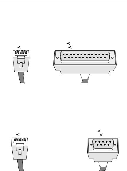
The COM port is a female RJ45 connector supporting EIA RS232C connections via cables with pinout configurations as specified in Figure 2-2 or Figure 2-3.
RJ45 Plug |
|
|
Female 25 Pin D-Shell |
||||
8 |
|
1 |
13 |
|
|
1 |
|
|
|
|
|||||
|
25 |
|
|
14 |
|||
|
|
||||||
|
|
|
|
|
|
|
|
|
|
|
|
|
|
|
|
|
|
|
Transmit...... |
Pin 1 ....... |
to ...... |
Pin |
3 ...... |
Receive |
|
|
||
|
|
|
Receive...... |
Pin 4 ....... |
to ...... |
Pin |
2 ...... |
Transmit |
|
|
||
|
Signal Ground...... |
Pin 5 ....... |
to ...... |
Pin |
7 ...... |
Signal Ground |
||||||
Data Carrier Detect...... |
Pin 2 ....... |
to ...... |
Pin 20 ...... |
Data Terminal Ready |
||||||||
Data Terminal Ready...... |
Pin 6 ....... |
to ...... |
Pin |
5 ...... |
Clear to Send |
|||||||
|
|
|
Figure 2-2. RJ45 to DB25 Connector Pinout |
|
|
|||||||
RJ45 Plug |
|
|
|
|
Female DB-9 |
|||||||
8 |
|
|
1 |
|
|
|
|
5 |
|
|
|
1 |
|
|
|
|
|
|
|
|
|
||||
|
|
|
|
|
|
9 |
|
|
6 |
|
||
|
|
|
|
|
|
|
|
|
||||
|
|
|
|
|
.....Transmit |
.......Pin 1 |
......to |
........Pin 2 |
Receive |
Receive..... |
Pin 4 ....... |
to ...... |
Pin 3 ........ |
Transmit |
Signal Ground..... |
Pin 5 ....... |
to ...... |
Pin 5 ........ |
Signal Ground |
Request to Send..... |
Pin 7 ....... |
to ...... |
Pin 7 ........ |
Ready to Send |
Clear to Send..... |
Pin 8 ....... |
to ...... |
Pin 8 ........ |
Clear to Send |
Figure 2-3. RJ45 to DB9 Connector Pinout
Page 2-4

Operating Specifications
2.2.3Supported MIB Groups
The STHI provides access to the following Management Information Base groups and their respective functionality:
Standard MIBs |
1 |
•MIB-2 (RFC 1231)
Cabletron Enterprise MIBs |
2 |
•Download
•MIB-II Extensions
•Token Ring FNB (Flexible Network Bus)
•DOT 5 Physical & Logical
•Token Ring Station Assignment
•Device
•PIC MIB (Product Information Chip MIB)
•Chassis MIB
2.2.4Ring Speed
The operating ring speed for the STHI may be set via the Ring Speed Switch on the front face of the STHI or by MIB commands via the SNMP Tool screen in Local Management.
The STHI hub’s Ring Speed switch setting is read only at power-up. In order to change the ring speed via the Ring Speed switch, the user must first change the switch setting and then reset the STHI (see Section 4.3, The Reset Button).
MIB commands override the Ring Speed switch setting. Once the switch setting has been overridden, the MIB command ring speed setting will remain in effect at all subsequent power-ups as long as the switch setting is not changed. MIB commands are accessible through the MIB Navigator screen on the intelligent hub’s Local Management application and through other SNMP network management software packages including Cabletron Systems’ Remote LANVIEW®/Windows.
The user may cancel the MIB override and regain switch control over the STHI hub’s ring speed by changing the current switch position and resetting the STH by the reset button.
Page 2-5

Operating Specifications
NOTE |
When cancelling a MIB override, the user may have to reset twice (as described in the steps below) to actually change the STHI hub’s ring speed by the switch.
To return to switch control from a MIB-overridden Ring Speed setting:
1.Regain switch control. Regardless of the actual desired ring speed, the user must toggle the switch out of its current position and then reset the STHI to put a switch-position change into effect, cancelling the MIB override.
2.Select the desired ring speed. If the Ring Speed switch setting is not yet the desired setting (it may now be the same as the setting dictated by the MIB command), the user must again change the switch setting and reset the STH to complete the change from the MIB-commanded speed setting to the desired switch-set speed setting,
2.2.5Ring Sequence
The ring sequence for the stations on the ring (the order in which stations are logically arranged on the ring) is determined by the physical location of each TCU connection, progressing in ascending stack number and port number order. The sequence is changed each time a station is inserted or de-inserted from a ring.
To determine the ring sequence, consider only those ports inserted into the ring. Beginning at the STHI hub’s lowest numbered inserted port, list in ascending numerical order the number of each inserted port. If STH hubs have been stacked to the STHI, then continue by listing those inserted in the STH hub numbered lowest in the stack. Repeatedly move to each next STH and list the inserted ports in numerical order until all ports inserted into the ring have been listed. The order is continuous, wrapping directly from the stack’s last inserted port to the first—from the bottom of the list, right back to the top.
Hubs that are bypassed from the stack’s common ring must TIP not be counted in the common ring sequence; they comprise
their own separate rings with separate ring sequences.
2.2.6Safety
This equipment is designed in accordance with UL478, UL910, NEC 725-2(b), CSA, IEC, TUV, VDE Class A, and meets FCC Part 15, Class A limits.
Page 2-6
 Loading...