


 Loading...
Cabletron Systems
MMAC-Plus™ Remote Management for the 9E312™ Ethernet Switch Module and 9E423™ Series Ethernet SmartSwitch Module
Notice
Cabletron Systems reserves the right to make changes in specifications and other information contained in this document without prior notice. The reader should in all cases consult Cabletron Systems to determine whether any such changes have been made.
The hardware, firmware, or software described in this manual is subject to change without notice.
IN NO EVENT SHALL CABLETRON SYSTEMS BE LIABLE FOR ANY INCIDENTAL, INDIRECT, SPECIAL, OR CONSEQUENTIAL DAMAGES WHATSOEVER (INCLUDING BUT NOT LIMITED TO LOST PROFITS) ARISING OUT OF OR RELATED TO THIS MANUAL OR THE INFORMATION CONTAINED IN IT, EVEN IF CABLETRON SYSTEMS HAS BEEN ADVISED OF, KNOWN, OR SHOULD HAVE KNOWN, THE POSSIBILITY OF SUCH DAMAGES.
Virus Disclaimer
Cabletron has tested its software with current virus checking technologies. However, because no antivirus system is 100% reliable, we strongly caution you to write protect and then verify that the Licensed Software, prior to installing it, is virus-free with an anti-virus system in which you have confidence.
Cabletron Systems makes no representations or warranties to the effect that the Licensed Software is virus-free.
Copyright 1996 by Cabletron Systems, Inc. All rights reserved.
Printed in the United States of America.
Order Number: 9031630-02 November 1996
Cabletron Systems, Inc.
P.O. Box 5005
Rochester, NH 03866-5005
Cabletron Systems, SPECTRUM, BRIM, DNI, FNB, INA, Integrated Network Architecture, LANVIEW, LANVIEW Secure, Multi Media Access Center, MiniMMAC, and TRMM are registered trademarks, and Bridge/Router Interface Modules, BRIM-A100, CRBRIM-W/E, CRXMIM, CXRMIM, Desktop Network Interface, Distributed LAN Monitoring, Distributed Network Server, DLM, DNSMIM, E1000, E2000, E3000, EFDMIM, EMM-E6, EMME, EPIM, EPIM-3PS, EPIM-A, EPIM-C, EPIM-F1, EPIM-F2, EPIM-F3, EPIM-T, EPIM-T1, EPIM-X, ESXMIM, ETSMIM, ETWMIM, FDCMIM-04, FDCMIM-08, FDMMIM, FDMMIM-04, Flexible Network Bus, FOMIM, FORMIM, HubSTACK, IRBM, IRM, IRM-2, IRM-3, Media Interface Module, MicroMMAC, MIM, MMAC, MMAC-3, MMAC-3FNB, MMAC-5, MMAC-5FNB, MMAC-8, MMAC-8FNB, MMAC-M8FNB, MMAC-Plus, MRX, MRXI, MRXI-24, MultiChannel, NB20E, NB25E, NB30, NB35, NBR-220/420/620, RMIM, SecureFast Packet Switching, SFPS, SPECTRUM Element Manager, SPECTRUM for Open Systems, SPIM-A, SPIM-C, SPIM-F1, SPIM-F2, SPIM-T, SPIM-T1, TPMIM, TPMIM-22, TPMIM-T1, TPRMIM, TPRMIM-36, TPT-T, TRBMIM, TRMM-2, TRMMIM, and TRXI are trademarks of Cabletron Systems, Inc.
i
AppleTalk, Apple, Macintosh, and TokenTalk are registered trademarks; and Apple Remote Access and EtherTalk are trademarks of Apple Computer, Inc.
SmartBoost is a trademark of American Power Conversion
ST is a registered trademark and C++ is a trademark of AT&T
Banyan and VINES are registered trademarks of Banyan Systems, Inc.
cisco, ciscoSystems, and AGS+ are registered trademarks; and cBus, cisco Router, CRM, IGS, and MGS are trademarks of cisco Systems, Inc.
GatorBox is a registered trademark; and GatorMail, GatorMIM, GatorPrint, GatorShare, GatorStar, GatorStar GX-M, and XGator are trademarks of Cayman Systems, Inc.
CompuServe is a registered trademark of CompuServe Incorporated
X Window System is a trademark of Consortium, Inc.
CTERM, DECnet, and ULTRIX are registered trademarks; and DEC, DEC C++, DECnet-DOS, DECstation, VAX DOCUMENT, VMA, and VT are trademarks of Digital Equipment Corporation
Fore Systems, ForeRunner, and ForeRunner ASX-100 are trademarks of Fore Systems, Inc.
PC/TCP is a registered trademark of FTP Software, Inc.
HP OpenView is a registered trademark of Hewlett-Packard, Inc.
AIX, IBM, OS/2, NetView, and PS/2 are registered trademarks; and AT, Micro Channel, PC, PC-DOS, PC/XT, Personal Computer AT, Operating System/2, Personal System/2, RISC System/6000, and Workplace Shell are trademarks of International Business Machines Corporation
i960 microprocessor is a registered trademark; and Intel and Multichannel are trademarks of Intel Corporation
Microsoft, MS-DOS, and Windows are registered trademarks of Microsoft Corporation
Chameleon, ChameleonNFS, Chameleon 32, IPX/link, and NEWT are trademarks of NETMANAGE, Inc.
NetWare and Novell are registered trademarks; and Internetwork Packet Exchange (IPX), IPX, and Network File System (NFS) are trademarks of Novell, Inc.
Motif and MS are registered trademarks; and Open Software Foundation, OSF, OSF/1, and OSF/Motif are trademarks of The Open Software Foundation, Inc.
Silicon Graphics and IRIS are registered trademarks; and Indigo and IRIX are trademarks of Silicon Graphics, Inc.
NFS, PC-NFS, SPARC, Sun Microsystems, and Sun Workstation are registered trademarks; and OpenWindows, SPARCstation, SPARCstation IPC, SPARCstation IPX, Sun, Sun-2, Sun-3, Sun-4, Sun386i, SunNet, SunOS, SunSPARC, and SunView are trademarks of Sun Microsystems, Inc.
OPEN LOOK and UNIX are registered trademarks of Unix System Laboratories, Inc.
Ethernet, NS, Xerox Network Systems and XNS are trademarks of Xerox Corporation
ii
ANNEX, ANNEX-II, ANNEX-IIe, ANNEX-3, ANNEX-802.5, MICRO-ANNEX-XL, and MICRO- ANNEX-ELS are trademarks of Xylogics, Inc.
MAXserver and Xyplex are trademarks of Xyplex, Inc.
Restricted Rights Notice
(Applicable to licenses to the United States Government only.)
1.Use, duplication, or disclosure by the Government is subject to restrictions as set forth in subparagraph (c) (1) (ii) of the Rights in Technical Data and Computer Software clause at DFARS 252.227-7013.
Cabletron Systems, Inc., 35 Industrial Way, Rochester, New Hampshire 03867-0505.
2.(a) This computer software is submitted with restricted rights. It may not be used, reproduced, or disclosed by the Government except as provided in paragraph (b) of this Notice or as otherwise expressly stated in the contract.
(b)This computer software may be:
(1)Used or copied for use in or with the computer or computers for which it was acquired, including use at any Government installation to which such computer or computers may be transferred;
(2)Used or copied for use in a backup computer if any computer for which it was acquired is inoperative;
(3)Reproduced for safekeeping (archives) or backup purposes;
(4)Modified, adapted, or combined with other computer software, provided that the modified, combined, or adapted portions of the derivative software incorporating restricted computer software are made subject to the same restricted rights;
(5)Disclosed to and reproduced for use by support service contractors in accordance with subparagraphs (b) (1) through (4) of this clause, provided the Government makes such disclosure or reproduction subject to these restricted rights; and
(6)Used or copied for use in or transferred to a replacement computer.
(c)Notwithstanding the foregoing, if this computer software is published copyrighted computer software, it is licensed to the Government, without disclosure prohibitions, with the minimum rights set forth in paragraph (b) of this clause.
(d)Any other rights or limitations regarding the use, duplication, or disclosure of this computer software are to be expressly stated in, or incorporated in, the contract.
(e)This Notice shall be marked on any reproduction of this computer software, in whole or in part.
iii
iv

Contents
Chapter 1 |
Introduction |
|
|
Using the 9E312 and 9E423 User’s Guide ................................................................. |
1-2 |
|
Related Manuals............................................................................................................ |
1-3 |
|
Software Conventions .................................................................................................. |
1-4 |
|
Common 9E312 and 9E423 Window Fields ....................................................... |
1-4 |
|
Using Buttons and Menus .................................................................................... |
1-5 |
|
Getting Help .................................................................................................................. |
1-6 |
|
Using On-line Help................................................................................................ |
1-6 |
|
Getting Help from Cabletron Systems Technical Support............................... |
1-6 |
|
9E312 and 9E423 Firmware.......................................................................................... |
1-7 |
Chapter 2 |
The 9E312/9E423 Module View |
|
|
Viewing Module Information...................................................................................... |
2-2 |
|
Front Panel Information........................................................................................ |
2-3 |
|
Menu Structure....................................................................................................... |
2-4 |
|
The 9E312/9E423 Module Port Status Display ................................................. |
2-7 |
|
The Chassis Manager Window ............................................................................ |
2-8 |
|
Viewing the Device Type ...................................................................................... |
2-9 |
|
Managing the Module .................................................................................................. |
2-9 |
|
Setting the Device Date and Time ....................................................................... |
2-9 |
|
Enabling and Disabling Bridge Ports................................................................ |
2-11 |
|
Using the Find Source Address Feature .................................................................. |
2-11 |
|
I/F Summary Information......................................................................................... |
2-12 |
|
Interface Description Fields................................................................................ |
2-13 |
|
Interface Performance Statistics/Bar Graphs .................................................. |
2-14 |
|
Interface Detail Window..................................................................................... |
2-15 |
|
Interface Detail Window Statistics ............................................................. |
2-16 |
|
Making Sense of Interface Statistics........................................................... |
2-18 |
|
Testing and Disabling the Current Interface.................................................... |
2-18 |
|
Using the Applications Pull-down menu......................................................... |
2-19 |
v

Contents
Chapter 3 |
9E312/9E423 Module Bridging |
|
|
Bridging Basics .............................................................................................................. |
3-1 |
|
More on Transparent Bridging............................................................................. |
3-2 |
|
An Overview of Remote Bridge Management.......................................................... |
3-2 |
|
The Bridge Status Window .......................................................................................... |
3-3 |
|
Bridge Status Window Information Fields......................................................... |
3-4 |
|
Accessing Other Management Options from the Bridge Status Window ..... |
3-5 |
|
Enabling and Disabling Bridging ............................................................................... |
3-6 |
|
Bridge Statistics ............................................................................................................. |
3-6 |
|
Performance Graphs.............................................................................................. |
3-7 |
|
Bridge Performance Graph Window Fields................................................ |
3-8 |
|
Configuring the Bridge Performance Graphs............................................. |
3-9 |
|
The Interface Statistics Window........................................................................... |
3-9 |
|
Interface Statistics Window Fields ............................................................. |
3-10 |
|
Bridge Spanning Tree.................................................................................................. |
3-11 |
|
Configuring the Bridge Spanning Tree Window............................................. |
3-13 |
|
Bridge Level Fields .............................................................................................. |
3-13 |
|
Bridge Port Level Fields...................................................................................... |
3-15 |
|
Changing Bridge Spanning Tree Parameters ................................................... |
3-17 |
|
Changing Bridge Priority ............................................................................ |
3-17 |
|
Changing the Spanning Tree Algorithm Protocol Type .......................... |
3-17 |
|
Changing Hello Time ................................................................................... |
3-18 |
|
Changing Max Age Time ............................................................................. |
3-18 |
|
Changing Forwarding Delay Time............................................................. |
3-18 |
|
Changing Port Priority................................................................................. |
3-19 |
|
Changing Path Cost...................................................................................... |
3-19 |
|
Filtering Database ....................................................................................................... |
3-19 |
|
Filtering Database Window Fields .................................................................... |
3-22 |
|
Configuring the Filtering Database................................................................... |
3-23 |
|
Altering the Ageing Time ............................................................................ |
3-24 |
|
Changing the Type of Entry ........................................................................ |
3-24 |
|
Changing the Receive Port .......................................................................... |
3-24 |
|
Changing the Port Filtering Action ............................................................ |
3-25 |
|
Adding or Deleting Individual Entries...................................................... |
3-25 |
|
Clearing All Permanent, Static, or Dynamic Entries................................ |
3-26 |
|
Using Port Source Addressing ........................................................................... |
3-26 |
|
Setting the Ageing Time............................................................................... |
3-27 |
|
Duplex Modes.............................................................................................................. |
3-28 |
|
The Duplex Modes Window............................................................................... |
3-28 |
|
Duplex Modes Window Fields ................................................................... |
3-29 |
|
Setting the Duplex Mode ............................................................................. |
3-30 |
Index
vi

Chapter 1
Introduction
How to use this guide; related guides; software conventions; getting help; 9E312 and 9E423 firmware versions
Welcome to the Cabletron Systems MMAC-Plus Remote Management for the
9E312™ Ethernet Switch Module and 9E423 ™ Series Ethernet SmartSwitch Modules User’s Guide. We have designed this guide to serve as a simple reference for using SPECTRUM Element Manager for the 9E312-12 Ethernet Switch Module, and the 9E423-24 and 9E423-36 Ethernet SmartSwitch Modules for the MMAC-Plus. These modules provide Ethernet connectivity to the Internal Network Bus (INB) backplane via high-speed packet switching.
In basic terms, a packet-switching device provides forwarding logic for packets incoming or outgoing on two or more network interfaces on the device. The forwarding logic on Cabletron’s MMAC-Plus architecture devices is based on three separate modes:
•Traditional 802.1d bridging based on physical layer address information.
•Traditional IP Routing based on logical layer address information.
•SecureFast™ Switching, which is high-performance switching based on source and destination MAC (physical) layer addresses. Packets received from a source address on a module’s protocol-dependent front panel network are converted into fixed-length, protocol-independent packets for transmission across a backplane, and then are re-converted at the destination device into the appropriate physical frame format for reception by the destination address. Future firmware and management software enhancements will allow an administratively defined connection-policy between end stations connected to SecureFast Switching devices.
The INB is the Cabletron-proprietary network bus for protocol-independent, high-speed packet or cell switching between connectivity modules that support front-panel Ethernet, FDDI, Token Ring, or ATM networks. The connectivity modules incorporate Cabletron’s SecureFast Switch (SFS) technology to provide high-performance packet switching based on source and destination MAC addresses, rather than on internet protocol (IP) addresses. By basing packet
1-1

Introduction
switching on physical layer information, the INB allows your network infrastructure to be protocol independent. The INB backplane consists of two channels (INB-1 and INB-2), each featuring a 64-byte wide data path capable of a sustained data transfer rate of 2 Gigabytes/second (4 Gigabytes/second for the combined channels). Currently, the connectivity modules will connect to one or the other channel.
The 9E312-12 Ethernet Switch Module is Cabletron’s first generation Ethernet INB module, and it is currently being field-upgraded to the 9E423. The device should be considered a prototype device for the INB, and management support for it should also be considered preliminary. The 9E312 supports thirteen network interfaces; one interface (Interface 1) to direct traffic over onto INB-1 of the MMAC-Plus Internal Network Bus (INB); and twelve RJ-45 10Base-T connectorsß.
The 9E423-24 Ethernet SmartSwitch™ Module is the second generation Ethernet INB module. It incorporates fast ASIC (application-specific integrated circuit) technology that boosts the forwarding rate of the module up to 750,000 frames per second. The 9E423-24 supports twenty-five network interfaces: one interface (Interface 1) to the INB-2 backplane, and two front panel RJ71 Telco connectors, each supplying 12 network interfaces via UTP or STP connectors. The 9E423 also incorporates an ASIC specially designed for embedded network trend and analysis tools.
The 9E423-36 Ethernet SmartSwitch module is similar to the 9E423-24, except that it supports thirty-seven network interfaces: one interface to INB-2, and three front panel RJ71 Telco connectors, each supplying 12 network interfaces via UTP or STP connectors.
Management is not available for either the INB 1 or INB 2 backplane, as data transmission across the INB is subject to hardware defaults.
The SecureFast Virtual Networking (SFVN) feature of the 9E423-24 and 9E423-36 (which allows switching configuration on a per-user level) is also not supported in firmware at the time this document was published. SFVN firmware is anticipated to be customer-released in late-1996, and remote management will follow shortly thereafter.
Using the 9E312 and 9E423 User’s Guide
Each chapter in this guide describes one major functionality or a collection of several smaller functionalities of the 9E312 or 9E423 Modules. This guide contains information about software functions which are accessed directly from the module’s Module View (either started from within MMAC-Plus Remote Management, or from a stand-alone icon representing the module).
1-2 |
Using the 9E312 and 9E423 User’s Guide |

Introduction
For information about management functions which are accessed via the SPECTRUM Element Manager platform, consult the Installing and Using SPECTRUM Element Manager and SPECTRUM Element Manager Utilities
User’s Guides; for more information about monitoring and controlling a configured MMAC-Plus chassis, refer to the Using MMAC-Plus Remote Management Guide.
Because the management windows documented in this manual are similar for all three devices — except that the 9E423 modules support more interfaces, sample windows will be taken from 9E423-24 Module management (unless there is an exception in appearance for the 9E312 Module). Note, too, that the 9E423-24 and 9E423-36 Ethernet SmartSwitch Modules will be referred to collectively as the 9E423 Modules.
Chapter 1, Introduction, provides a list of related documentation, describes certain software conventions, and shows you how to contact Cabletron Systems Technical Support.
Chapter 2, The 9E312 and 9E423 Module View, describes the visual display of the 9E312 and 9E423 Modules and explains how to use the mouse within the Module View; the operation of several chassis-level management functions — such as changing the chassis display, enabling and disabling ports, and setting device date and time — is also described here, as are the I/F Summary windows, which provide information from the MIB-II Interface Group.
Chapter 3, 9E312 and 9E423 Bridging, provides a comprehensive look at all management options associated with the bridge mode of the 9E312 and 9E423 switches, including Bridge Performance Graphs, Spanning Tree, the Filtering Database, and Duplex Mode operation. The bridge mode is currently implemented in the forwarding/filtering logic between the module’s front panel networks and the interface to the INB backplane. When the modules support SecureFast networking, they will operate either in traditional bridge mode or SecureFast mode; the two modes cannot operate simultaneously.
We assume that you have a general working knowledge of Ethernet IEEE 802.3 type data communications networks and their physical layer components, and that you are familiar with general bridging concepts.
Related Manuals
The MMAC-Plus Remote Management for the 9E312 Switch Module and 9E423 Series SmartSwitch Modules User’s Guide is only part of a complete document set designed to provide comprehensive information about the features available to you through SPECTRUM Element Manager. Other guides which include important information related to managing the 9E312 or 9E423 Modules include:
Cabletron Systems’ Using MMAC-Plus Remote Management Guide
Cabletron Systems’ Installing and Using SPECTRUM Element Manager Guide
Cabletron Systems’ SPECTRUM Element Manager Utilities User’s Guide
Related Manuals |
1-3 |
Introduction
Cabletron Systems’ Network Troubleshooting Guide
Microsoft Corporation’s Microsoft Windows User’s Guide
For more information about the capabilities of the 9E312 or 9E423 Modules, consult the appropriate hardware documentation.
Software Conventions
SPECTRUM Element Manager’s device user interface contains a number of elements which are common to most windows and which operate the same regardless of which window they appear in. A brief description of some of the most common elements appears below; note that the information provided here is not repeated in the descriptions of specific windows and/or functions.
Common 9E312 and 9E423 Window Fields
Similar descriptive information is displayed in boxes at the top of most devicespecific windows in SPECTRUM Element Manager, as illustrated in Figure 1-1.
|
|
|
|
|
|
|
Device |
|
|
|
|
Location |
|
|
|
|
|
|
|
|
|
|
|
|
|
|
|
|
|
|
|
|
|
|
|
|
|
|
|
||
|
|
|
|
|
|
|
Name |
|
|
|
|
|
|
|
||||||
|
|
|
|
|
|
|
|
|
|
|
|
|
|
|
|
|
|
|
|
|
|
|
|
|
|
|
|
|
|
|
|
|
|
|
|
|
|
|
|
|
|
|
|
IP Address |
|
|
|
|
|
|
|
|
|
|
|
|
|
|
MAC |
|
|
|
|
|
|
|
|
|
|
|
|
|
|
|
|
|
|
|
Address |
|
|
|
|
|
|
|
|
|
|
|
|
|
|
|
|
|
|
|
|
|
|
|
|
|
|
|
|
|
|
|
|
|
|
|
|
|
|
|
|
|
|
|
|
|
|
Figure 1-1. Sample Window Showing Informational Text Boxes
1-4 |
Software Conventions |

Introduction
Device Name
Displays the user-defined name of the device. The device name can be changed via the System Group window; see the Generic SNMP Management Module Guide for Windows for details.
IP Address
The Internet Protocol address assigned to the 9E312 or 9E423 Module; this field will display the IP address you have used to create the 9E312 or 9E423 Module in the MMAC-Plus Chassis Setup window or to create its icon via SPECTRUM Element Manager. IP addresses are assigned via Local Management.
Location
Displays the user-defined location of the device. The location is entered through the System Group window; see the Generic SNMP Guide for details.
MAC Address
Displays the manufacturer-set MAC address of the interface through which
SPECTRUM Element Manager is communicating with the 9E312 or 9E423
Module. MAC addresses are factory-set and cannot be altered.
Up Time
Displays the amount of time, in an X days hh:mm:ss format, that the 9E312 or 9E423 has been running since the last start-up.
Informational fields describing the ports being modeled are also displayed in most windows:
Port Number
Displays the number of the monitored port.
Using Buttons and Menus
This button, that appears at the bottom of most windows, lets you exit a window and terminate any unsaved changes you have made (if applicable).
Use these three buttons to save changes in a window and set them at the managed device (if applicable). You may also have to use the Cancel button to close a window after you have made changes and set them.
This button brings up a Help text box with information specific to the current window. For more information concerning Help buttons, see Getting Help, later in this chapter.
Software Conventions |
1-5 |
Introduction
Some buttons, like the two above, call up a menu listing the windows, screens, or commands available for that topic.
Any menu topic followed by ... (three dots) — for example Statistics... — calls up a window or screen associated with that topic.
Getting Help
This section describes different methods of getting help for questions or concerns you may have while using SPECTRUM Element Manager.
Using On-line Help
You can use the 9E312 or 9E423 Module window  buttons to obtain information specific to the device. When you click on a Help button, a window will appear which contains context-sensitive on-screen documentation that will assist you in the use of the windows and their associated command and menu options. Note that if a Help button is grayed out, on-line help has not yet been implemented for the associated window.
From the Help menu accessed from the Module View window menu bar, you can access on-line Help specific to the Module View, as well as bring up the Chassis Manager window for reference. Refer to Chapter 2 for information on the Module View and Chassis Manager windows.


 All of the SPECTRUM Element Manager help windows use the standard Microsoft NOTE Windows help facility; if you are unfamiliar with this feature of Windows, you can select
Help —>How to Use Help from the Program Manager window, or consult your Microsoft Windows User’s Guide.
Getting Help from Cabletron Systems Technical Support
If you need support related to SPECTRUM Element Manager, or if you have any questions, comments, or suggestions related to this manual or any of our products, please feel free to contact Cabletron Systems’ Technical Support via one of the following methods:
1-6 |
Getting Help |

Introduction
By phone: |
Monday through Friday between 8 AM and 8 PM |
|
Eastern Standard Time at (603) 332-9400 |
By mail: |
Cabletron Systems, Inc. |
|
PO Box 5005 |
|
Rochester, NH 03866-5005 |
By CompuServe®: |
GO CTRON from any ! prompt |
By Internet mail: |
support@ctron.com |
FTP |
ftp.ctron.com (134.141.197.25) |
Login |
anonymous |
Password |
your email address |
By BBS: |
(603) 335-3358 |
Modem Setting |
8N1: 8 data bits, 1 stop bit, No parity |
For additional information about Cabletron Systems products, visit our World Wide Web site: http://www.cabletron.com/
9E312 and 9E423 Firmware
SPECTRUM Element Manager has been tested against customer release firmware versions up to 1.00.14 for both the 9E312 MMAC-Plus Ethernet Switch Module and the 9E423-24 MMAC-Plus Ethernet SmartSwitch Module, and up to the internal firmware version 1.03.01 for the 9E423-36 MMAC-Plus Ethernet SmartSwitch Module; if you have an earlier version of firmware and experience problems, contact Cabletron Systems Technical Support for upgrade information.
|
As a general rule, firmware versions for new products are liable to change rapidly; contact |
NOTE |
Cabletron Systems Technical Support for upgrade information for the latest customer |
|
release of firmware. |
9E312 and 9E423 Firmware |
1-7 |

Introduction
1-8 |
9E312 and 9E423 Firmware |

Chapter 2
The 9E312/9E423 Module View
Accessing the Module View; information displayed in the Module View window; the logical module view
— menu structure and information, the Port Status display, the Chassis Manager window, the Device Type window; module management functions — setting device date and time, enabling and disabling ports; I/F Summary and Detail information
The 9E312/9E423 Module View window is the main screen that immediately informs you of the status of your 9E312/9E423 Module via a color-coded, graphical display of the module’s front panel that shows its individual ports in bridge mode. The Module View window serves as a single point of access to all other 9E312/9E423 Module windows and screens, which are discussed in the following chapter.
To open the 9E312/9E423 Module View window from the MMAC-Plus Chassis View:
1.Click once on the 9E312/9E423 Module board index shown in the MMAC-Plus chassis to display a menu.
2.Select Device View, and the Module View window will appear.
You can also access the Module View from a 9E312/9E423 Module icon. Either double-click on the appropriate device icon (illustrated in Figure 2-1, below) in a SPECTRUM Element Manager map or the Device List View, or use the following menu or tool bar options.
Figure 2-1. 9E312/9E423 INB Ethernet Switch Module Icons
2-1
The 9E312/9E423 Module View
1.Using the mouse, click on the 9E312/9E423 Module icon to be monitored (in a map or the Device List View). The icon will be highlighted.
2.Select Device —> Manage from the SPECTRUM Element Manager
platform’s menu bar, or select  from the tool bar; the Module View window will appear.


 To model your 9E312/9E423 Module as an individual device from SPECTRUM Element NOTE Manager, you must make sure that you select Chassis Manager mode for launching the
icon. Refer to your Installing and Using SPECTRUM Element Manager Guide for more information.
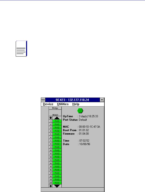
Viewing Module Information
The 9E312/9E423 Module View window (Figure 2-2) provides a graphic representation of the 9E312/9E423 Module, including a color-coded port display which immediately informs you of the current configuration and status of the module and its ports.
Figure 2-2. 9E312/9E423 Module View Window
2-2 |
Viewing Module Information |

The 9E312/9E423 Module View
By clicking in designated areas of the module’s graphical display (as detailed later in this chapter), or by using the menu bar at the top of the Module View window, you can access all of the menus that lead to more detailed deviceand portlevel windows.
When you move the mouse cursor over a management “hot spot” the cursor icon will TIP change into a “hand”  to indicate that clicking in the current location will bring up a
management option.
Note also that there are scroll arrows at the top and bottom of the port stack of the 9E423 Modules’ port display. Use these arrows to scroll through the port stack.
Front Panel Information
The areas above and to the right of the main module display area provide the following device information:
|
Preliminary versions of 9E312 module firmware may provide incomplete address |
NOTE |
information or firmware version information. |
IP
The Internet Protocol address assigned to the 9E312/9E423 Module appears in the title bar of the Module View window; this will display the IP address you have used to create the 9E312/9E423 Module in the MMAC-Plus Chassis Setup window or to create its icon via SPECTRUM Element Manager. IP addresses are assigned via Local Management.
Connection Status 
This color-coded area indicates the current state of communication between
SPECTRUM Element Manager and the 9E312/9E423 Module.
•Green indicates the 9E312/9E423 Module is responding to device polls (valid connection).
•Blue indicates an unknown contact status — polling has not yet been established with the 9E312/9E423 Module.
•Red indicates the 9E312/9E423 Module is not responding to device polls (device is off line, or device polling has failed across the network for some other reason).
Up Time
The amount of time, in a day(s) hh:mm:ss format, that the 9E312/9E423 Module has been running since the last start-up.
Viewing Module Information |
2-3 |

The 9E312/9E423 Module View
Port Status
If management for your device supports a variable port display, this field will show the display currently in effect. If only a single port display is available — as is the case for the 9E312/9E423 Module — or if the default view is in effect, this field will state Default.
MAC
The physical layer address assigned to the interface through which SPECTRUM Element Manager is communicating with the 9E312/9E423 Module.
Unless your management station is communicating through the front panel of the module, this will reflect the MAC address of the SMB 10 interface on the module (to the 10 Mb/sec System Management Bus). MAC addresses are hard-coded in the device, and are not configurable.
Boot Prom
The revision of BOOT PROM installed in the 9E312/9E423 Module.
Firmware
The revision of device firmware stored in the 9E312/9E423 Module’s FLASH PROMs.
Time
The current time, in a 24-hour hh:mm:ss format, set in the 9E312/9E423 Module’s internal clock.
Date
The current date, in an mm/dd/yy format, set in the 9E312/9E423 Module’s internal clock.


 You can set the date and time by using the Edit Device Date and Edit Device Time NOTE options on the Device menu, see Setting the Device Date and Time, later in this
chapter, for details.
Menu Structure
By clicking on various areas of the 9E312/9E423 Module View display, you can access menus with deviceand port-level options, as well as utility applications which apply to the device. The following illustration displays the menu structure and indicates how to use the mouse to access the various menus:
2-4 |
Viewing Module Information |

The 9E312/9E423 Module View
Figure 2-3. 9E312/9E423 Module View Menu Structure
The Device Menu
From the Device Menu at the Module View window menu bar, you can access the following selections:
•Device Type..., which displays a window containing a description of the device being modeled.
•Edit Device Time... and Edit Device Date..., which allow you to set the 9E312/9E423 Module’s internal clock.
•System Group..., which allows you to manage the 9E312/9E423 Module via SNMP MIB II. Refer to the Generic SNMP Management Module Guide for Window for further information.
•I/F Summary, which lets you view statistics (displayed both graphically and numerically) for the traffic processed by each network interface on your device, including a detailed Transmit and Receive traffic breakdown for each interface. It also lets you access SNMP MIB-I and MIB-II windows for device management.
•Bridge Status..., which opens a window that provides an overview of bridging information for each port, and allows you to access all other bridge-related options. Refer to Chapter 3, 9E312/9E423 Module Bridging, for more information.
Viewing Module Information |
2-5 |
The 9E312/9E423 Module View
•Find Source Address..., which opens a window that allows you to search the 802.1d Filtering Database of the 9E312/9E423 to determine which switching interface a specified source MAC address is communicating through. If the MAC address is detected as communicating through the switch, the port display will flash to indicate the switch interface of interest.
•Exit, which closes the 9E312/9E423 Module View window.
The Utilities Menu
The Utilities menu provides access to any utilities provided by SPECTRUM Element Manager for use with the 9E312/9E423 Module. These utilities include the MIBTree utility, which provides direct access to the 9E312/9E423 Module’s MIB information, and the RMON utility, a remote monitoring utility which is implemented by many of Cabletron Systems’ intelligent devices. These selections are also available from the Utilities menu at the top of SPECTRUM Element Manager’s main window.
Refer to your Utilities User’s Guide for information on these utilities.
The Help Menu
The Help Menu has three selections:
•MIBS Supported, which brings up the Chassis Manager window, described later in this chapter.
•Chassis Manager Help, which brings up a help window with information specifically related to using the Chassis Manager and Module View windows.
•About Chassis Manager..., which brings up a version window for the Chassis Manager application in use.
The Bridge Menu
The Bridge menu is available by clicking on the Bridge label above the bridge port display. It offers access to the following bridge-specific options, which are discussed thoroughly in Chapter 3, 9E312/9E423 Module Bridging:
•Spanning Tree..., which lets you set the Spanning Tree Algorithm parameters for bridging on your 9E312/9E423 Module.
•Disable/Enable Bridge, which allows you to halt or start bridging across the device.
•Module Type..., which displays a window containing a description of the device being modeled.
•Performance Graph..., that displays a statistics window for traffic across the entire bridge.
•Filtering Database..., which displays a window to configure the 9E312/9E423 Module bridge’s acquired and permanent filtering databases to filter or forward traffic across the 9E312/9E423 Module.
2-6 |
Viewing Module Information |
Loading...