

Cabasse MC-40-MINORCA, MC-40-JAVA, MC-40-FORMENTERA, MC-40-CABRERA, MC-40-MERCURE Owners Manual [en, fr, de]
...Page 1

MC40
notice d’installation des enceintes acoustiques
loudspeakers owner’s manual
betriebsanleitung für lautsprecherboxen
minorca•java•majorca
cabrera
•
formentera•mercure
www.cabasse.com
Page 2
f r a n ç a i s e n g l i s h d e u t s c h
1
3
2
4 5
6
d>1,5m/d>5ft
d
d
Page 3
7
Cinch RCA LINE IN
Cinch RCA LINE IN / Cinch RCA LINE IN Buchsen
8
Cinch RCA LINE OUT
Cinch RCA LINE OUT / Cinch RCA LINE OUT Buchsen
9
Bornes haut-parleurs HIGH LEVEL INPUT (amplificateur)
HIGH LEVEL INPUT connectors
HIGH LEVEL INPUT (vom Verstärker)
0
Bornes haut-parleurs HIGH LEVEL OUTPUT (vers enceintes)
HIGH LEVEL OUTPUT connectors
HIGH LEVEL OUTPUT (zu den Lautsprechern)
-
Alimentation secteur / Power supply / Netzstecker
=
Commutateur 115/230 V
AC voltage selector
/ Betriebspannungsshalter
q
Interrupteur POWER/ POWER / NETZ SHALTER
w
Réglage LEVEL/ LEVEL / LAUTSTÄRKEREGLER
e
Réglage de la fréquence de coupure- CROSSOVER FREQUENCY
CROSSOVER FREQUENCY / ÜBERGANGSFREQUENZREGLER
r
PHASE/ PHASE / PHASE
Amplificateur / Amplifier /Verstäker MERCURE
LR
7
7
8
-
=
0
rq
ew
9
Page 4
f r a n ç a i s
INSTRUCTIONS DE SECURITE
Explication des symboles -
L’éclair dans un triangle
équilatéral avertit de
l’existence de tension élevée dangereuse non isolée à l’intérieur du
coffret du produit, d’une valeur
suffisante pour présenter un risque d’électrocution.
Le point d’exclamation dans un triangle équilatéral aver-
tit de l’existence d’instructions importantes quant à l’utilisation et la maintenance dans la documentation jointe à ce
produit.
Instructions -
Toutes les instructions de sécurité et d’utilisation doivent avoir été lues avant d’allumer tout appareil
pour la première fois.
Retenez les instructions -
Elles doivent servir de référen-
ce permanente pour tout ce qui suit.
Tenez compte des avertissements -
Les avertissements
présents sur le produit ou dans les notices d’utilisation doivent
être pris en compte.
Suivez les instructions -
Toutes les instructions d’utilisation
et de mise en œuvre doivent être scrupuleusement suivies.
Nettoyage -
Débranchez l’appareil avant tout nettoyage.
N’utilisez pas de solutions nettoyantes sous forme liquide ou
en aérosols. Employez de préférence un chiffon humide.
Accessoires -
N’utilisez pas d’accessoires qui ne soient pas
explicitement recommandés par le constructeur, sous peine
de risquer divers accidents.
Eau et humidité -
L’appareil ne doit pas être utilisé près de
l’eau, par exemple à proximité d’une baignoire, d’un évier,
dans un sous-sol humide, près d’une piscine, ou de tout ce
qui y ressemble de près ou de loin.
Chariots et supports - La manutention doit
être effectuée seulement avec des chariots et supports agréés par le fabricant.
> Attention aux chariots de manutention
Installation sur mobiliers et supports -
Ne placez pas
cet appareil sur un support instable, qu’il s’agisse de pieds,
trépieds, tables, étagères, etc. Il pourrait tomber et causer des
blessures sérieuses à un enfant ou un adulte qui se trouverait
à proximité.
Ventilations -
L’appareil doit être positionné de telle sorte
qu’il ne gêne pas sa propre ventilation. Par exemple, il ne doit
pas être installé sur un lit, un canapé, une couverture ou des
surfaces similaires qui pourraient bloquer ses orifices d’aération. Il ne doit pas non plus être encastré dans des enceintes
confinées comme des étagères étroites ou des meubles qui
pourraient limiter la quantité d’air disponible aux entrées d’air.
Alimentation -
L’appareil ne doit être relié qu’à une source
électrique du type écrit dans le mode d’emploi ou conforme à
la sérigraphie sur le produit. Si vous n’êtes pas sûr du type de
courant fourni à l’endroit où vous vous trouvez, adressez-vous
à votre revendeur ou à la compagnie électrique locale.
Protection des câbles d’alimentation -
Le cheminement
des câbles d’alimentation doit être prévu de telle sorte qu’ils ne
puissent pas être piétinés, pincés, coincés par d’autres appa-
reils posés dessus, et une attention toute particulière doit être
accordée à l’adéquation des prises et à la liaison du cordon avec
l’appareil.
Foudre -
Pour une meilleure protection de l’appareil pendant les orages ou s’il doit rester inutilisé pendant une longue
période, débranchez le cordon d’alimentation et débranchez
la prise d’antenne, vous éviterez ainsi les risques de détérioration dus à la foudre ou aux surtensions.
Surcharges électriques -
Ne surchargez pas les prises d’alimentation, les prolongateurs ou les rappels d’alimentation. Il
pourrait en résulter incendies ou électrocutions.
Corps et liquides étrangers -
On doit être attentif à ne
jamais laisser entrer d’éléments ou de liquides étrangers dans
l’appareil. Ils pourraient occasionner incendies ou électrocutions. Ne versez jamais aucun liquide d’aucune sorte sur l’appareil.
Entretien -
L’utilisateur ne doit pas tenter de s’occuper des
opérations de maintenance au-delà de celles décrites dans le
mode d’emploi. Tout ce qui dépasse le simple niveau de l’entretien doit être effectué par un personnel qualifié.
Maintenance -
Dans les cas suivants, vous devez impérativement débrancher votre appareil et le faire vérifier par un
technicien qualifié :
■ l’alimentation ou la prise a été endommagée.
■ des corps étrangers ou du liquide se sont introduits dans
l’appareil.
■ l’appareil a été exposé à la pluie ou a été aspergé d’eau.
■ l’appareil ne semble pas marcher correctement alors que
vous l’utilisez dans le cadre de ses instructions de fonctionnement normal. Ne manipulez que les contrôles couverts par le
mode d’emploi. Toute autre procédure pourrait le détériorer
et nécessiter l’intervention d’un technicien qualifié.
■ l’appareil est tombé ou bien sa carrosserie est endomma-
gée.
■ l’appareil affiche des performances nettement modifiées.
Pièces détachées -
Si la réparation a nécessité l’utilisation
de pièces détachées, assurez-vous que le technicien a bien utilisé les références préconisées par le fabricant ou présentant les
mêmes caractéristiques que les pièces originales. Des pièces non
conformes peuvent provoquer incendies, électrocutions ou
autres.
Vérifications -
Après toute intervention sur l’appareil, demandez au technicien d’effectuer des tests afin de garantir que
l’appareil fonctionne en toute sécurité.
Exposition aux fortes températures -
L’appareil doit
être tenu éloigné de sources de chaleur comme radiateurs,
chauffage divers, amplificateurs, ou tous autres éléments susceptibles de le placer dans des conditions de températures
anormalement élevées.
Sacs plastiques -
Ne pas laisser les sacs plastiques de l’emballage à portée des enfants afin d’éviter tout risque d’étouffement.
Vous venez d’acheter des enceintes Cabasse et nous vous remercions de votre confiance.
Dans le but d’optimiser au maximum votre installation, nous vous recommandons
de lire attentivement cette notice.
Attention !
pour éviter les chocs électriques, introduire la lame
la plus large de la fiche dans la borne correspondante et pousser
jusqu’au fond
Valable aux USA, au Canada et autres pays concernés
Page 5

f r a n ç a i s
DEBALLAGE DES ENCEINTES
1
Ouvrir le côté mentionné sur le carton, replier sur les cotés les
rabats supérieurs du carton et retirer le cache de l’enceinte. Puis
retourner l’emballage avec son contenu, vider le carton de son
contenu et sortir l’enceinte de son emballage. Nous vous
conseillons de conserver l’emballage de votre enceinte à plat
pour une utilisation ultérieure éventuelle.
POSITIONNEMENT ET PLACEMENT
DES ENCEINTES ACOUSTIQUES
Positionnement des enceintes
Nos enceintes acoustiques sont prévues pour fonctionner
en position verticale, afin de respecter la courbe polaire
des haut-parleurs.
La plupart de nos modèles sont livrés avec un jeu de pointes ou
cônes de découplage
2
. Ces accessoires sont à visser dans
l’empla cement prévu sous vos enceintes. Ces pointes ou cônes
de découplage permettent d’assurer une meilleure stabilité de
l’enceinte tout en limitant les résonances pouvant être générées
par certains types de sols comme les planchers par exemple.
Les enceintes sont livrées avec un tissu de protection en face
avant. II est possible de les utiliser sans ce tissu. Enlevez le
cadre en exerçant une légère traction horizontale sur sa partie
supérieure pour rompre sa liaison magnétique avec l’ébénisterie de votre enceinte. Pour remettre le cadre en place, présentez
le devant la face avant de l’enceinte et approcher doucement
le cadre jusqu’à ce que les liaisons magnétiques soient établies. Procédez à ces opérations délicatement pour éviter une
usure prématurée de la partie du revêtement couvrant les
aimants insérés sur la face avant de l’ébénisterie.
Nous vous recommandons de garder cette protection en place
pour mieux protéger les haut-parleurs de votre enceinte
3
.
Le champ magnétique des moteurs des haut-parleurs va rayonner au delà de l’enveloppe de l’enceinte acoustique. Il faut
donc éloigner d’environ 50 cm les appareils et objets sensibles
à ce type de rayonnement (téléviseurs, écrans d’ordinateur,
disquettes informatiques, bandes magnétiques audio ou vidéo,
cartes à puces...). Les enceintes centrales ne sont pas concernées par ce type de problème car elles sont blindées magnétiquement.
Placement des enceintes dans une pièce
Outre la position des enceintes, il faut tenir compte de leur
emplacement dans la pièce, les propriétés acoustiques d’un
local étant un facteur capital dans la retransmission du son.
Le placement optimal
pour une écoute stéréo classique 2.0
4
■ Si l’on considère que d est la distance qui sépare les deux
enceintes, celle-ci doit être supérieure à 1.5 m. Les deux
enceintes doivent être à égale distance de la zone d’écoute qui
forme avec elles un triangle équilatéral.
■ Les haut-parleurs doivent être dirigés vers la zone d’écoute.
■ Les enceintes doivent, de préférence, diffuser dans le sens
de la plus grande dimension de la pièce.
■ D’une façon générale, on doit éviter de positionner les
enceintes dans les coins d’une pièce, car la disposition en angle
favorise Ies fréquences graves. De même, les enceintes doivent
se situer à une distance d’au moins 20 cm du mur.
■ Toujours dans le but d’obtenir une réponse équilibrée, il est
recommandé de surélever les enceintes compactes d’environ
30 à 40 cm du sol avec des supports pour enceintes, les tweeters
de l’enceinte devant se situer approximativement à la hauteur
des oreilles de l’auditeur lorsque celui-ci est en position assise.
■ Aucun élément (table, fauteuil...) ne doit gêner la propaga-
tion directe entre les enceintes et l’auditeur. Un effet de masque,
même partiel, déséquilibre complètement la reproduction
sonore car il provoque une atténuation des fréquences aiguës
et dans la majorité des cas des médiums également.
■ La disposition des en ceintes dans des niches est également
en généra l à pr oscrire car elle mod ifie la courb e de
réponse de l’enceinte, particulièrement dans les fréquences
basses. S’il est impossible d’adopter une autre disposition, on
doit veiller à ce que l’enceinte s’encastre avec le minimum de
jeu dans la niche, pour éviter l’apparition de résonances diverses.
Par ailleurs, la partie visible du tissu devra être à l’extérieur de
la niche.
Le placement optimal
pour une écoute stéréo en 2.1
5
Dans le cadre d’une écoute stéréo avec 2 enceintes ou 2 satellites et 1 caisson de graves, nous vous conseillons de placer le
caisson de graves dans la zone écoute avant. Le placement
du caisson contre un mur renforce l’extrême grave et limite les
réflexions de 80 à 200Hz. Cependant, pour obtenir le meilleur
résultat, il est toujours nécessaire de faire des essais d’emplacement en fonction de l’acoustique de la pièce.
Le placement optimal
pour une écoute Home Cinéma ou 5.1
6
Pour la disposition d’un ensemble home cinéma, il est important d’apporter la plus grande attention à la disposition des
enceintes supplémentaires spécifiques.
■ L’enceinte centrale doit être placée le plus près possible de
l’écran en recherchant la position dans le lieu d’écoute qui
apporte la plus grande cohésion sur les dialogues entre le son
et I’image. En pratique, cela revient à placer l’enceinte centrale au-dessus de l’écran si les enceintes principales sont plus
basses que celui-ci, et en dessous si les enceintes principales sont
plus hautes.
■ Les enceintes arrière, voies d’effet ou surround doivent être
disposées contre les murs latéraux, légèrement en hauteur.
Elles doivent être situées légèrement en arrière de la zone
d’écoute.
■ Le caisson de graves doit être placé dans la zone d’écoute
avant. Son placement contre un mur renforce l’extrême grave
et limite les réflexions de 80 à 200 Hz. Cependant, pour obtenir le meilleur résultat, il est toujours nécessaire de faire des
essais d’emplacement en fonction de l’acoustique de la pièce.
Votre amplificateur audio-vidéo permet le réglage des niveaux
et des distances de chaque enceinte. Ce réglage doit être ajusté avec soin de manière à obtenir une parfaite cohésion entre
les sources sonores.
Il est nécessaire d’éteindre tous les appareils avant la connexion
des enceintes. Pour le branchement de vos enceintes acoustiques, il faut tenir compte de la section des câbles et du respect des phases.
BRANCHEMENT
Section des câbles
Pour conserver toutes les
qualités des enceintes
acoustiques et éviter les
pertes de puissance, il faut
que la résistance électrique
des câbles de branchement
entre I’enceinte et I’amplificateur soit la plus faible possible.
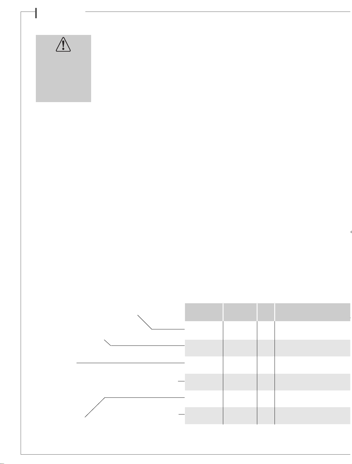
Pour vous aider à choisir la meilleure section de câble pour
votre installation, veuillez suivre le tableau récapitulatif .
Distance Section
ampli -enceinte
4,5 m 1,5 mm
2
6 m 2 mm
2
7,5 m 2,5 mm
2
9 m 3 mm
2
12 m 4 mm
2
Page 6
f r a n ç a i s
Phase
Les enceintes et les amplificateurs
ont leurs bornes de branchement
repérées. Il y a deux façons courantes d’effectuer ce repère: soit
une borne rouge ou repère+, soit
une borne noire ou repère -.
Dans tous les cas, il faut que les deux
canaux soient branchés de façon
identique, c’est à dire par exemple
que la borne rouge ou+de l’encein-
te aille à la borne rouge ou+ de l’amplificateur ; la borne noire oude I’enceinte ira dans ce cas à la borne noire ou- de I’amplificateur.
BRANCHEMENT HOME CINEMA
AVEC CAISSON DE GRAVES
Placement du caisson de graves
Les caissons de graves n’ont pas à priori une position impérative
par rapport à la zone d’écoute si la fréquence des filtres de coupure est aux alentours de 150 Hz, en effet, en dessous de cette
fréquence, le caisson n’est pas directif, et il est impossible de
détecter l’endroit d’où viennent les basses. Pour obtenir le meilleur
résultat, il est toujours nécessaire de faire des essais d’emplacement, afin d’obtenir la meilleure réponse possible dans les fréquences basses, en fonction de l’acoustique de la pièce.
Branchement du caisson de graves
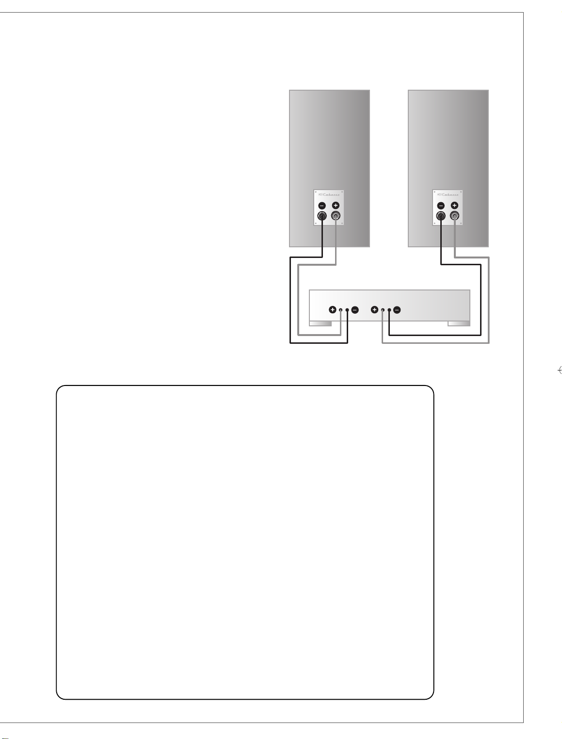
Le branchement de la modulation peut s’effectuer de 2 façons:
■ soit avec les entrées et sorties
Cinch RCA LINE IN7et
LINE
OUT
8
en utilisant des cordons coaxiaux blindés,■ soit en
utilisant les bornes haut-parleurs
HIGH LEVEL INPUT9et
HIGH LEVEL OUTPUT0et du câble haut-parleur classique.
Les entrées sont stéréophoniques, le mélange des graves gauche
L (left)
et droite
R (right)
se fait dans l’amplif icateur. Si le
signal provenant de la source est mono, une seule entrée
gauche
L (left)
ou droite
R (right)
devra être utilisée.
Branchement avec les entrées et sorties
Cinch RCA LINE IN7et LINE OUT8en utilisant
des cordons coaxiaux blindés
■ Connexion par les prises LINE IN
7
:
Si votre préamplificateur ou amplificateur audio vidéo possède une sortie stéréophonique à bas niveau, relier les sorties
gauche
L (left)
et droite
R (right)
du préamplificateur aux
entrées
LINE IN7gauche
L (left)
et droite
R (right)
du caisson
de graves.
Si votre appareil ne possède qu’une seule sortie monopho-
nique (subwoofer/LFE), relier celle-ci à l’entrée
LINE IN
7
gauche
L (left)
ou droite
R (right)
indifféremment.
■ Connexion par les prises LINE OUT
8
Les prises
LINE OUT8gauche
L (left)
et droite
R (right)
délivrent la modulation mise à l’entrée
LINE IN7. Ces sorties
LINE OUT8peuvent vous servir à brancher l’amplificateur
de puissance destiné aux enceintes principales.
Branchement avec les bornes haut-parleurs
HIGH LEVEL INPUT9et HIGH LEVEL OUTPUT
0
et du câble haut-parleur classique
■ Connexion avec les bornes HIGH LEVEL INPUT
9
Si votre amplificateur intégré Hi Fi ne possède pas de sortie à
bas niveau, brancher les sorties de l’amplificateur aux extrémités
HIGH LEVEL INPUT9gauche
L (left)
et droite
R (right)
du
caisson de graves. Vous pouvez brancher le caisson de graves
sur les bornes de votre amplificateur qui servent à brancher les
haut-parleurs. En branchant les sorties gauche et droite de
votre amplificateur aux entrées gauche et droite du caisson
de graves, faire bien attention à ne pas inverser les câbles en
phase, car vous risqueriez de provoquer une panne sur votre
amplificateur principal.
■ Connexion avec les bornes HIGH LEVEL OUTPUT
0
Ces bornes délivrent la même modulation que celles que vous
avez mises à l’entrée
HIGH LEVEL INPUT9. Elles permettent
de rebrancher par exemple les enceintes principales.
MC 40 Utilisation Voies Haut-parleurs Ef
1
(e
MINORCA bibliothèque 3 1 tweeter-médium coaxial BC10
voie principale /socle 1 x 17 cm 17MD18LB1
JAVA au sol 3 1 tweeter-médium coaxial BC10
voie principale 2 x 17 cm 17MD18LB1
MAJORCA au sol 3 1 tweeter-médium coaxial BC10
voie principale 2 x 21 cm 21MD18LB1
CABRERA sur/sous 3
1 tweeter-médium coaxial BC10
voie centrale* écean 2 x 17 cm 17MD18LB1TV
FORMENTERA bibliothèque 3 1 tweeter-médium coaxial BC10
voie d’effets /au mur 1 x 17 cm 17MD18LB1
MERCURE au sol 11x21 cm 21MT4
caisson de graves
* blindage magnétique
SPECIFICATIONS
ET CARACTERISTIQUES TECHNIQUES
Attention
Avant tout branchement,
s’assurer que votre
tension secteur correspond
bien à la tension
secteur sélectionnée
sur le commutateur
115 V - 230 V t.
Page 7
f r a n ç a i s
Secteur
L’alimentation-sert à alimenter le caisson de graves. La
sélection de la tension d’alimentation est effectuée par le
commutateur
115 V- 230 V=. La mise en route s’effectue par
l’interrupteur
POWERq, en le mettant dans la position
STAND
BY
ou la position ON. Dans la position
STAND BY
, l’appareil
se mettra en veille s’il n’y a pas eu de modulation pendant
quelques minutes. Dès que la modulation réapparaît, le caisson de graves se met en fonctionnement.
Réglages
■ LEVEL
w
Pour un premier réglage du volume, mettre le
CROSSOVER
FREQUENCY
e
à environ 120 Hz, et monter progressivement
le
LEVELwjusqu’à ce que vous estimiez que le niveau des
graves est suff i s ant. Il faud ra sans doute r et o ucher
le nive au
LEVELwquand vous aurez trouvé les bons réglages
de fréquence
CROSSOVER FREQUENCYeet de
PHASEr.
■ CROSSOVER FREQUENCY
e
Ce potentiomètre sert à régler la fréquence supérieure de la
plage de travail du caisson de graves. Ce réglage va dépendre
du type d’enceintes principales qui est utilisé avec le caisson de
graves et de leur fonctionnement dans la pièce. Des essais
seront nécessaires pour déterminer la meilleure fréquence.
■ PHASE
r
Suivant la disposition du caisson de graves par rapport aux
enceintes satellites, on peut être amené à inverser la phase du
caisson de graves pour obtenir un son de meilleure qualité ; on
commute alors l’inverseur de position 0° à la position 180°.
A vous de déterminer quelle sera la phase la meilleure suivant
le réglage du potentiomètre
CROSSOVER FREQUENCYe.
Attention, si vous avez un deuxième caisson de graves, il faut
impérativement que cet inverseur de phase soit dans la même
position que celui du premier. Nous vous invitons à consulter
sur www.cabasse.com les réglages spécifiques que nous préconisons pour l’utilisation de nos caissons de graves.
ENTRETIEN
Les ébénisteries de la gamme MC40, réalisées avec un revêtement spécifique enduit de deux vernis de protection et d’une
pellicule anti-rayures, ne nécessitent aucun entretien particulier, le matériau utilisé étant un produit de très haute technicité. Elles peuvent être nettoyées avec un chiffon humide.
En suivant les conseils d’installation, de branchement et d’emploi explicités dans cette notice, vous êtes assurés d’un fonctionnement parfait de vos enceintes acoustiques. Nous recevons tous les jours des lettres de clients satisfaits du choix de
leurs enceintes et ces lettres sont pour nous la plus belle récompense de nos efforts.
Étant donné l’évolution des techniques mises en œuvre pour une fiabilité accrue et une recherche constante de qualité optimale,
Cabasse se réserve le droit d’apporter toutes modifications aux modèles présentés sur les fiches techniques ou les documents publicitaires.
1W/1m en fréquences nominale minimale nominale crête standards hxlxp (en kg)
(en dB) (en Hz) (en Hz) (en ohms) (en ohms) (en Watt) (en Watt) (en cm)
cerisier clair/cadre noir +cadre beige
40 x 23x 28 9,5
cerisier pourpre/
cadre noir +cadre beige
cerisier clair/cadre noir +cadre beige
110 x 25x 35 27
cerisier pourpre/
cadre noir +cadre beige
cerisier clair/cadre noir +cadre beige
115 x 29x 35 31
cerisier pourpre/
cadre noir +cadre beige
89,5 900- 70-23 000 8 3,2 75 550
cerisier clair/cadre noir +cadre beige
18 x 49 x 35 12
cerisier pourpre/
cadre noir +cadre beige
cerisier clair/cadre noir +cadre beige
35 x 32x 15 8
cerisier pourpre/
cadre noir +cadre beige
cerisier pourpre
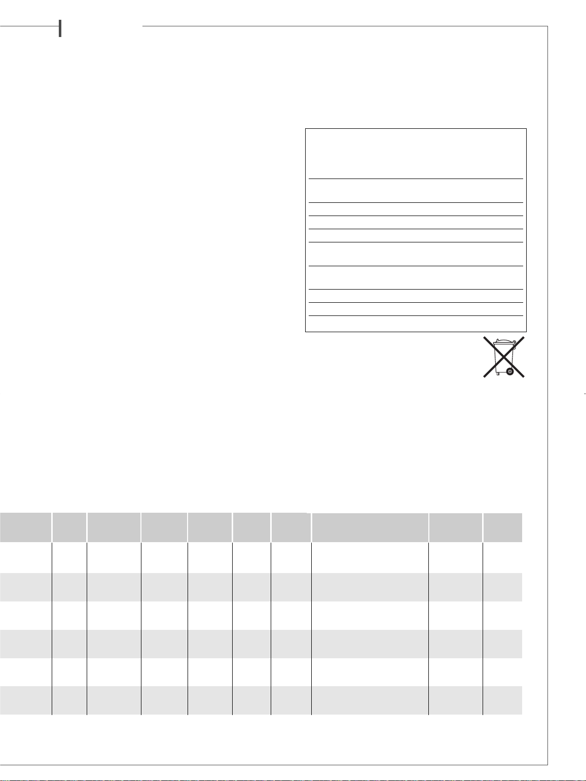
MARQUAGE DEEE
Traitement des appareils électriques
et électroniques en fin de vie (applicable
dans les pays de l’Union européenne).
Ce symbole, représentant une poubelle sur roues barrée d’une
croix, apposé sur le produit, indique que ce produit ne doit
pas être traité avec les déchets ménagers. Il doit être remis à un
point de collecte pour le traitement des équipements électriques et électroniques en fin de vie. En s’assurant que ce produit est bien mis au rebut de manière appropriée, vous aiderez
à prévenir les conséquences négatives potentielles pour l’environnement et la santé humaine. Le recyclage des matériaux
aidera à conserver les ressources naturelles. Pour toute information supplémentaire au sujet du recyclage de ce produit,
vous pouvez contacter votre municipalité, votre déchetterie ou
le magasin où vous avez acheté le produit.
CAISSON DE GRAVES ACTIF
MERCURE MC40
Pression
impulsionnelle maximale 114 dB
Sélecteur de phase 0°phase normale
180°phase inversée
Prises d’entrée 2 bas niveau- 2 haut niveau
Alimentation 115/ 230 V AC-50 /60 Hz
Consommation maximum 165W
Consommation mode veille 0,49W @ 230VAC
0,5W @ 115VAC
Consommation mode arrêt 0,04W @ 230VAC
0,04W @ 115VAC
Température d’utilisation +5°C à +35°C
Température de stockage -5°C à +40°C
Taux d’humidité en utilisation 40% à 70%
Page 8
SAFET Y INSTRUCTIONS
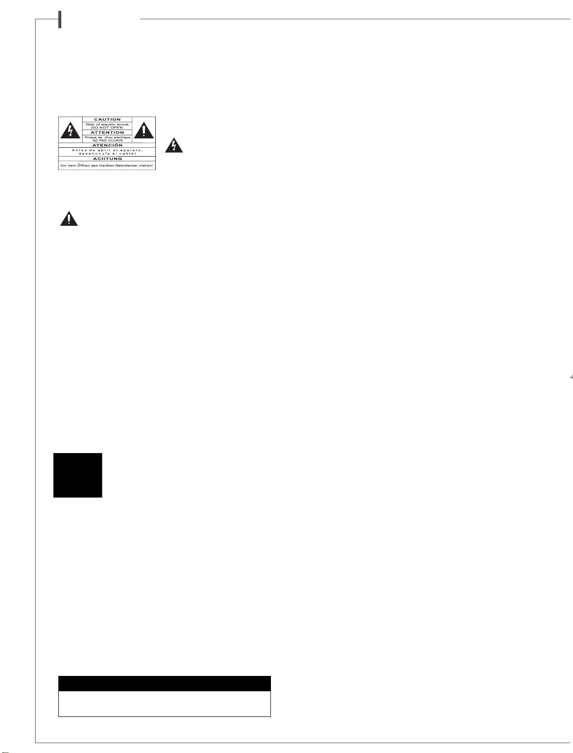
Explanation of graphical
symbols -
The lightning flash
with arrowhead symbol,
within an equilateral tri-
angle, is intended to alert you
to the presence of uninsulated
“dangerous voltage” within the product’s enclosure that may
be of sufficient magnitude to constitute a risk of electric shock
to persons.
The exclamation point within an equilateral triangle is
intended to alert you to the presence of important operating and maintenance (servicing) instructions in the literature accompanying the appliance.
Instructions -
Carefully read through all the safety and
operating instructions before switching on any device for the
first time.
Keep these instructions in mind -
They will be con-
stantly referred to through this manual.
Pay special care to warnings -
All the warning labels on
the product or warning notes in the user’s manual must be
followed.
Follow the instructions -
Follow carefully all the instal-
lation and operation instructions.
Cleaning -
Always take off the power cord before cleaning
the device. Do not use cleaning solvent, whether liquid or air
spray. Using a soft damp cloth is recommended.
Accessories -
To avoid incidents, only use accessories express-
ly recommended by Cabasse.
Water and moisture -
The product shall not be used in
damp or wet locations, such as humid basements, next to a
bathtub, sink, swimming pool or any other similar conditions.
Carts and Stands - The appliance should be
used only with a cart or stand that is recommended by the manufacturer.
> Portable cart warning
Installation on a piece of furniture and stands -
Do not place this device on an unsteady surface, i.e. a stand,
tripod, table, shelf, etc. It may fall and cause serious injury to
a nearby child or adult.
Ventilation outlets -
The device shall not be placed in a
position that restrains the operation of its fans. Avoid installing
the device on a bed, couch, blanket or other similar surfaces
that may prevent the appropriate air flow. Do not install the
device in a confined space, such as a book shelf or other piece
of furniture, that could prevent sufficient air from flowing
freely.
Power -
The device shall only be connected to a source of
power compliant to the one described in this manual or on relevant printed labels on the product. If you are not sure of the
type of power available, please contact your reseller or the
local power company.
Power cords -
The power cords must be laid out in such a
way that they cannot be walked on, pinched, bent under other devices. Also pay special attention to the matching of the
plugs and the connection of the cord to the device.
Lightning -
For better protection against lightning or if the
device must remain unused for long stretches of time, unplug
the power cord and antenna jack. This minimizes potential
damages due to lightning or line surges.
Overloads -
Avoid overloading the power plugs, extension
cords or power relays. This could result in fire or electric shocks.
Foreign bodies and liquids -
Avoid letting foreign materials or liquids enter the device. They could cause fire or electric shocks. Never spill any liquid on the device.
Maintenance -
Users must never attempt to maintain the
device on their own, except for those maintenance operations
described in this manual. Any task beyond regular user maintenance must be performed by qualified service operators.
Troubleshooting -
You must unplug your device from the
power supply and have it checked by a qualified technician if:
■ The power supply or the plug is damaged.
■ Foreign bodies or liquid penetrated the device.
■ The device was exposed to dripping or splashing.
■ The device does not seem to work correctly under normal
operating conditions. Only operate the controls described in
this manual. Any other operation could damage the device
and require on-site visit of a qualified technician.
■ The device has fallen or its housing is damaged.
■ The performances of the device are strongly altered.
Spare parts -
If spare parts are needed to repair the device,
make sure that the technician followed the manufacturer’s
recommendations or that the replacing parts feature the same
specifications as the original ones. Non-compliant parts can
result in multiple damages, including fire or electric shocks.
Checks -
After any servicing of the device, ask the technician to perform appropriate testing to make sure that the
device works safely.
Exposure to high temperatures -
The device should
be kept away from heating sources, such as radiators, heaters,
amplifiers or any other similar item likely to make the operating temperature rise excessively.
Plastic bags -
Keep them away from children to prevent
any risk of suffocation.
UNPACKING
1
After opening the top carton flaps, remove the grille. Then fold the
carton flaps right back and invert the carton contents. Lift the
carton clear of the contents and remove the inner packaging from
the speakers. We suggest you to retain the packing for future use.
POSITIONING
Speakers positioning
Our speakers have been designed to function in a vertical position. Under these conditions, the polar response is most uniform.
The majority of our models are delivered with a set of decoupling spikes or cones
2
, these accessories are to be screwed in
the inserts under the cabinets. These accessories ensure the
stability of the speaker while limiting resonance coming from
e n g l i s h
Thank you very much for choosing Cabasse speakers.
Please read carefully these instructions before setting up your speakers.
Caution !
To prevent electric shock, match wide blade plug to wide
slot, insert fully.
Applicable for USA, Canada or where approved for usage
Page 9
certain types of grounds like wood floors.
Speakers are delivered with a front grille to protect drivers. It
is possible to use them without this front grille, by gently pulling its top end in order to cut off its magnetic link with the
magnets to the front panel. To get the grill back in place, position it in front of the speaker and approach it to the front
panel until the magnetic link is effective. These operations
must be carried out very smoothly in order not to damage prematurely the veneer covering the magnets on the front panel of
the speaker.
We recommend this protection to be kept on to prevent accidental damage to the drivers
3
.
Powerful drivers generate magnetic fields that can extend
beyond the boundaries of the speaker cabinet. We recommend you keep magnetically sensitive articles (TV, computer
screen, computer discs, audio and video tapes, swipe cards...)
at least 1.5 ft (50 cm) away from the speaker. Cabasse centre
speakers or the ones marked «TV» are not concerned with
this, being magnetically shielded.
Positioning speakers in a room
In addition to vertical position of the speakers themselves,
their location in the listening room, as well as the acoustical characteristics of the room, are also very important. As it is impossible to indicate a typical location of speaker systems without
a few tests, we suggest several general rules that are important to apply in order to obtain the best listening results.
Optimal positioning for a 2.0 or stereo system
4
■ For the ideal positioning of your speakers follow diagram.
If «d» is the distance between the two speakers, this distance
must be higher than 5 ft (1.5 m) and the two speakers must be
at equal distance from the listening area which forms with
them an equilateral triangle.
■ The drivers must be directed towards the listening area.
■ The speakers should be located so that their diffusion follows
the longest dimension of the room.
■ Generally speaking it is better to avoid putting the speakers
in the corners of a room as this amplifies the low frequencies
and tends to enhance the room resonances. If possible it is
better to place the speakers at least 8 inches (20 cm) from
the walls.
■ Moreover, in order to obtain a more accurate frequency res-
ponse, it is recommended to raise a compact speaker from
12 to 16 inches (30 to 40 cm) above the floor by placing them
on stands. The tweeters of the speakers must be roughly at
the same height of the listener’s ear when the listener is in sitting position.
■ No solid object or piece of furniture should be placed between
the speakers and the listener. An effect of mask, even partial disturbs completely the sound reproduction as it attenuates the
high frequencies and also, in most cases, the midrange frequencies.
■ Placing the speakers in niches is not recommended. Unless
designed for this application, bookshelf placement will alter the
frequency response of the speaker, especially in the low frequencies. If a bookshelf location cannot be avoid, the speaker
should be set up to minimize various resonance, and the visible
part of the grille must be outside the niche.
Optimal positioning for a 2.1
or stereo with a subwoofer system
5
For a stereo listening with 2 speakers or 2 satellites and 1 subwoofer, we recommend you to place the subwoofer in the
front listening area. The placement of the subwoofer against
a wall reinforces the low frequencies and limit the reflections
from 80 to 200 Hz. However to obtain the best results, it is
always necessary to carry out tests according to the acoustic
of the room.
Optimal positioning for a 5.1
or home theatre system
6
Setting up a multi-channel Audio-Video system requires great
care when positioning the specific AV speakers.
■ The centre speaker should be placed as close as possible to
the screen and where it sounds best from your listening spot
while offering the optimal picture/dialogues cohesion. Theoretically, the screen should be located within a virtual triangle
formed by the acoustical centres of the main speakers and the
centre speaker. Practically speaking, this means that the principal speaker should be placed above the screen if the main
speakers are below it, and below the screen if the main speakers are above. The centre speaker should also, if possible, be
set slightly back from the others, so that it is located at the same
distance from the listener as the main speakers.
■ The rear speakers or surround should be placed against the
side walls, at listening height. They should not be positioned
far behind the listening zone.
■ The subwoofer should be placed in the front listening area,
its position against a wall reinforces the extreme low register and
limits the reflections between 80 and 200 Hz. However to
obtain the best result, it is always necessary to carry out tests
according to the acoustics of the room.
Your AV processor enables the adjustment in level and delay of
each of the 5/6/7 channels of your system. Fine-tuning is necessary to obtain a perfect sound stage.
Turn off all the amplifiers before interconnecting them to the
loudspeakers. In order to connect loudspeakers properly, it is
most important to keep in mind the following two factors:
cable section and phase.
CONNECTION
Cable section
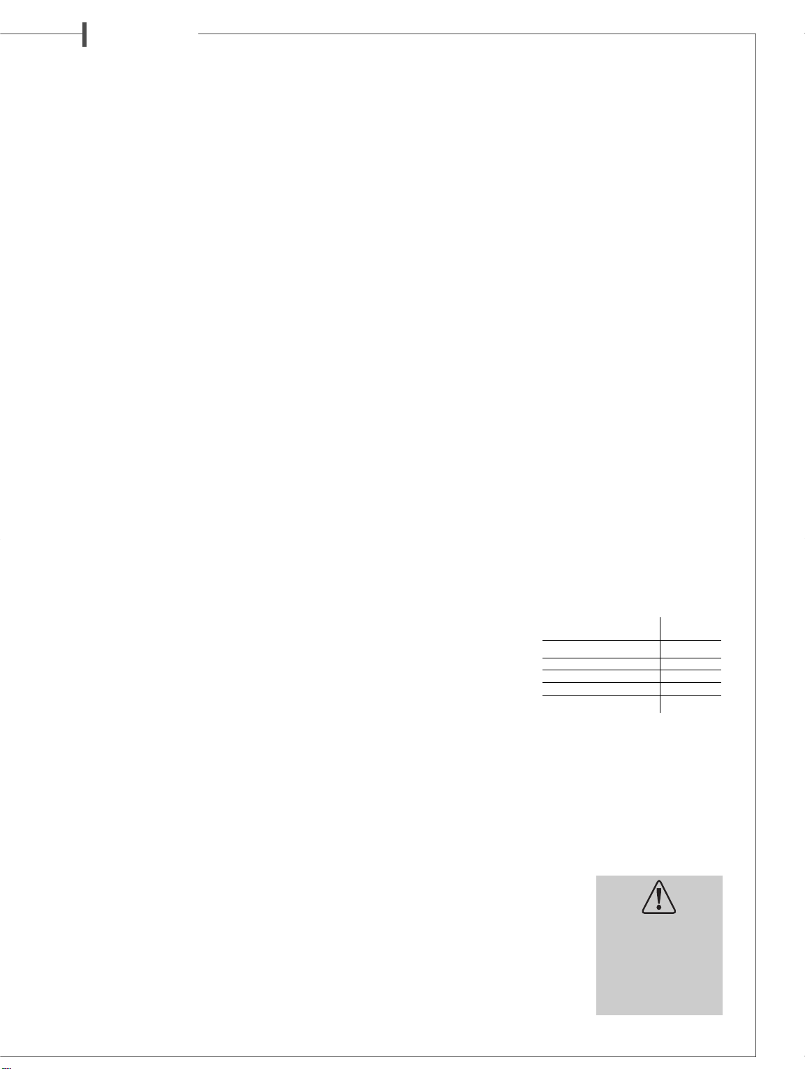
To get the full sonic
potential of Cabasse
loudspeak ers and
avoid power losses,
the cables connecting
the speakers to the
power amplifier must have the lowest possible electrical resistance. To help you in choosing the correct cable gauge, follow
diagram.
Phase
In order to maintain the phase relationship and frequency
balance of the loudspeaker system, both loudspeakers must be
properly connected to the power amplifier. When properly
connected, the cones of the drivers of both loudspeakers will
move in the same direction when driven by identical speakers
will move in the same signals. If the cones move in opposite
directions, the resulting out of
phase signals will create a perceptible power loss, particularly
in the low frequencies. The stereophonic message will also be
degraded. Amplifier and speaker
manufacturers typically indicate
connection polarity in one of two
ways: red and black or plus and
minus. In either case, always
connect red or plus to red or plus
e n g l i s h
Lenght between recommanded
amplifier and loudspeakers section
4.5 m 1.5 mm
2
6 m 2 mm
2
7.5 m 2.5 mm
2
9 m 3 mm
2
12 m 4 mm
2
Attention,
before operating the unit,
be sure that the
operating voltage
of your unit is identical
with that of your local
power voltage.
Page 10
e n g l i s h
and black or minus to black or minus. Connections should
be identical for both channels. To check that the speakers are
in correct phase, switch the system to mono while music is
being played. if the amplifier does not have a phase inversion
switch, it will be necessary to change over the connections on
one only of the loudspeakers. If in correct phase, the image
should be distinctly located between the loudspeakers with a
slight loss of bass and low midrange level. If the image is confused and not centrally located and there is a drastic loss of bass
and low midrange level, recheck your connections.
HOME THEATER CONNECTIONS
WITH AN ACTIVE SUBWOOFER
Subwoofer positioning
With a crossover point below or around 150 Hz, the installation position of subwoofers is not limited as human ears and
brains are not able to identify the emitting point of such low
frequencies. To get the best result, it is recommended to try different positions and choose the one giving the best response
in the low frequencies, taking into account the room acoustics.
Hooking up the subwoofer
2 possibilities are offered to connect the subwoofer with your
system:
■ the low level one requiring the use of the
and
LINE OUT8terminals and shielded coaxial connectors,
■ the high level one requiring the use of the
INPUT
loudspeaker cables.
The inputs are stereo ones, the mix of the
low frequencies being done by the amplifier of the subwoofer.
If the input signal is already mono, only one input
(right)
and
HIGH LEVEL OUTPUT0terminals and standard
9
should be used.
Cinch RCA LINE IN
HIGH LEVEL
L (left)
and
R (right)
L (left)
7
or
Interconnections with the Cinch RCA LINE IN
7
and LINE OUT8connectors
■ Connections to the LINE IN
If your preamplifier or your integrated amplifier is fitted with
a stereo low-level output, then connect its
outputs to the
woofer. If your amplifier offers a one mono output, connect it
to either the
■ Connections from the LINE OUT
The signal from the
tors is the one being brought in by the
IN
7
be used to bring the signal to the amplifier powering the main
loudspeaker.
L (left)
and
L (left)
or the
L (left)
connectors filtered at 40 Hz. These outputs can thus
7
L (left)
and
R (right)
R (right) LINE IN9inputs of the sub-
R (right)
subwoofer
LINE IN9inputs.
8
and
R (right) LINE OUT8connec-
L (left)
and
R (right) LINE
Interconnections with the speaker terminals
■ Connections to HIGH LEVEL INPUT
If the preamp section of your Hi Fi or audio-video system is not
fitted with a low level output, you should then connect the
subwoofer by using its loudspeaker terminals. When connecting the
L (left)
and
R (right)
to the
HIGH LEVEL INPUT9plugs of the subwoofer, be care-
ful not to cross (-) and (+) cord of either
channel. Such a phase inversion might damage your main
amplifier.
■ Connections HIGH LEVEL OUTPUT
These outputs can be used to bring the signal to the main
loudspeaker systems.
The signal from the
PUT
plugs is the one being brought in by the
0
R
INPUT
the signal to the main loudspeaker systems.
connectors. These outputs can thus be used to bring
9
speaker outputs of your amplifier
L (left)
and
R (right) HIGH LEVEL OUT-
9
0
plugs
L (left)
plugs
or
R (right)
HIGH LEVEL
SPECIFICATIONS & TECHNICAL DATA
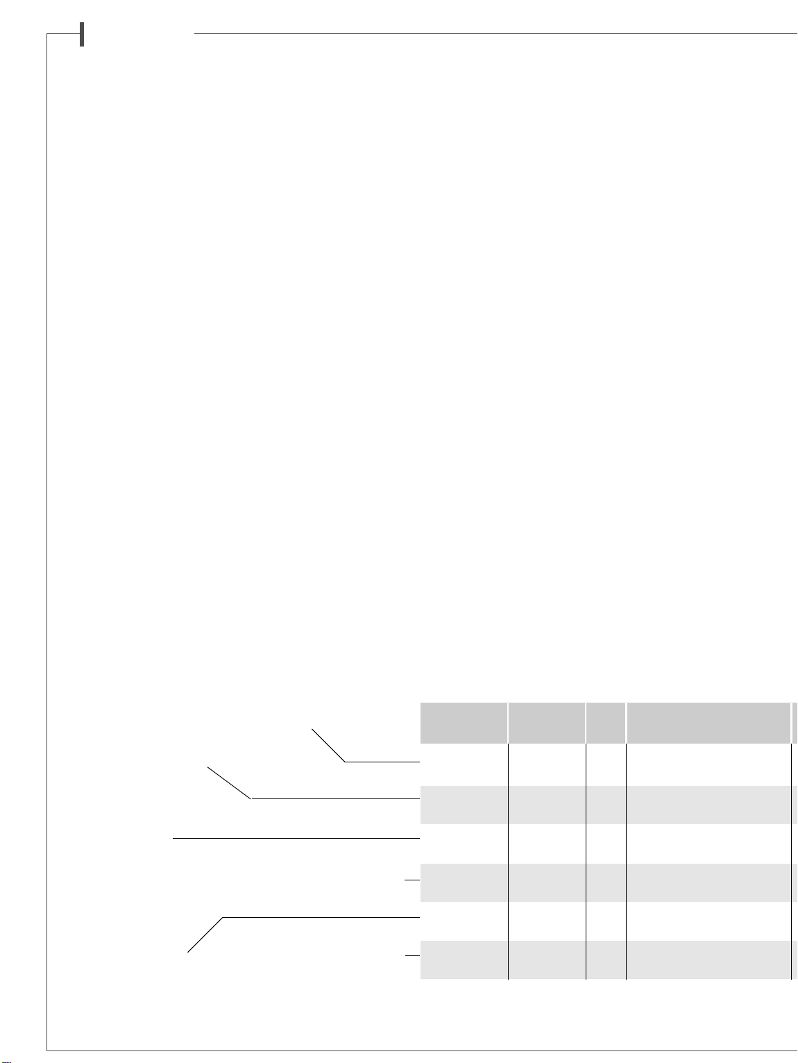
MC40 Position Ways Drivers complement S
MINORCA booksheft/ 3 1 coaxial midrange-tweeter BC10
main speaker stand 1 x 17 cm (7”) 17MD18LB1
JAVA floorstanding 3 1 coaxial midrange-tweeter BC10
main speaker 2 x 17 cm (7”) 17MD18LB1
MAJORCA floorstanding 3 1 coaxial midrange-tweeter BC10
main speaker 2 x 21 cm (8”) 21MD18LB1
CABRERA on/under 3 1 coaxial midrange-tweeter BC10
center* screen 2 x 17 cm (7”) 17MD18LB1TV
FORMENTERA on wall/ 3 1 coaxial midrange-tweeter BC10
surround booksheft 1 x 17 cm (7”) 17MD18LB1
MERCURE floorstanding 11x21 cm (8”) 21MT4
active subwoofer
* Magnetic shielding
1
Page 11
e n g l i s h
Power supply
The
AC in-cord must be connected to the mains to supply
the subwoofer. The selection of the right voltage 115V-230 V
is done with 115V-230V
or ON. With the switch on the
=
. Switch
STAND BY
POWERq, on
position, the unit will
STAND BY
mute after a few minutes without input signal. The system
turns on automatically when signal comes back.
Adjustments
■ LEVEL
w
For a first volume adjustment, position the
FREQUENCY
at around 120 Hz, and turn slowly the
e
CROSSOVER
LEVEL
w
clockwise from minimum level up to a position where you feel that
the subwoofer sound level is appropriate. A check of the level
adjustment will be necessary after following steps.
■ CROSSOVER FREQUENCY
e
This potentiometer adjusts the cut-off frequency which determines the working bandwidth of the subwoofer. This adjustment should be done according to the specifications of the
main speakers and the room acoustics. Choose the best frequency after various listening tests.
■ PHASE
r
For a better sound integration of the subwoofer in the main
system, the
PHASErof the subwoofer might have to be
inverted (180° position), depending on the distance between
the subwoofer and the main speakers. You have to check the
PHASEreach time you move your speakers and each time
you adjust the
CROSSOVER FREQUENCY
re
.
Attention, if you use 2 subwoofers, both phase switches must
be on the same position.
Our web site
www.cabasse.com
will give you the specific adjust-
ments we recommend for the use of our active subwoofers.
MAINTENANCE
The MC40 cabinets are made of medium density fiber panels,
protected by synthetically veneer with two coats of varnish
and a special anti-scratch film. This hi-tech veneer does not
require any specific care. Use a wet cotton waste for cleaning,
or any cleaning device for wood or plastic.
ACTIVE SUBWOOFER MERCURE MC40
Pulsed sound pressure 114 dB
Phase switch 0° normal
180° reverse
In put 2 low level- 2 hight level
Voltage 115/ 230 V AC-50/ 60 Hz
Maximum power consumption 165W
Standby power consumtion 0.49W @ 230VAC
0.5W @ 115VAC
Power consumption when off 0.04W @ 230VAC
0.04W @ 115VAC
Useable temperature range +5°C à +35°C
Storage temperature -5°C à +40°C
Useable humidity range 40% to 70%
WEEE MARK
Disposal of Wastes of Electrical &
Electronic Equipment (Applicable in the
European Union)
This symbol on the product, consisting of the crossed-out
wheeled bin, indicates that this product shall not be treated
as household waste. Instead it shall be handed over to the
applicable collection point for the disposal of electrical and
electronic equipment at the end of life.
By ensuring this product is disposed of correctly, you will help
prevent potential negative consequences for the environment
and human health, which could otherwise be caused by inappropriate waste handling of this product. The recycling of
materials will help to preserve natural resources. For more
detailed information about recycling of this product, please
contact your local city office, your household waste disposal
service or the shop where you purchased the product
1W/1m points response impedance impedance handling power finish hxlxp (cm) (kg)
Cross-over
(dB) (Hz) (Hz) (ohms) (ohms) (Watt) (Watt) hxlxp (”) (lbs)
Because of technical improvements already under way in our constant search for optimum quality,
Cabasse
Frequency Nominal Minimum Power Peak Standard Dimensions Weight
cherry with anthracite + beige front grills
beige front grills
cherry with anthracite + beige front grills
beige front grills
cherry with anthracite + beige front grills
beige front grills
cherry with anthracite + beige front grills
beige front grills
cherry with anthracite + beige front grills
beige front grills
cherry
reserves the right to modify all the models presented in specification sheets, advertising materials and manuals without prior notice.
40 x 23x 28 9,5
3/4
15”
x 9” x 11”
110 x 25x 35 27
1/3
5/6
43”
x 9”
3/4
x 13”
115 x 29x 35 31
1/4
45”
13”
16”
5/12
x 11”
3/4
13”
18 x 49 x 35 12
1/12
x 13”
3/4
x 5”
11/12
x 19”
x 12”
11/12
x 14”
1/4
3/4
7/12
1/6
7”
35 x 32x 15 8
44 x 36x 45 22
21 lbs
59 lbs
68 lbs
26 lbs
17 lbs
48 lbs
Page 12
d e u t s c h
SICHERHEITSHINWEISE
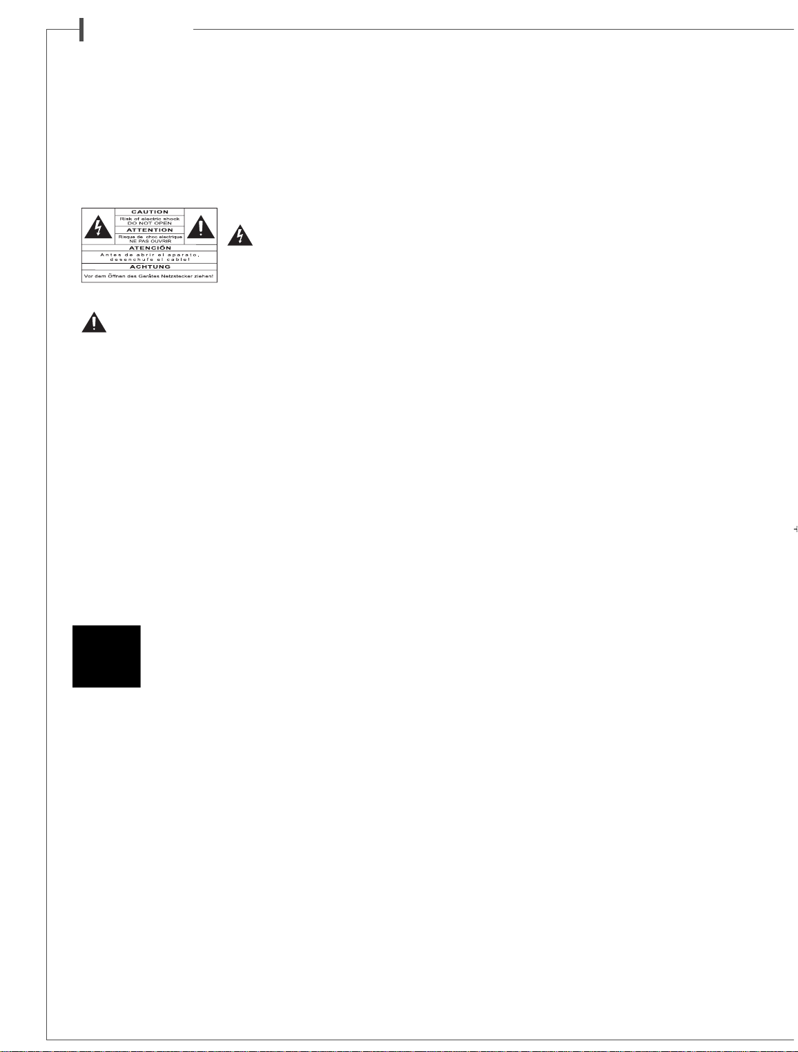
Bedeutung der Symbole :
Der Blitz mit Pfeilspitze
in einem gleichseitigen
Dreieck dient als Warnhinweis
für unisolierte Stromspannung
innerhalb des Gerätegehäuses,
die stark genug sein kann, um eine Stromschlaggefahr zu bilden.
Das Ausrufezeichen in einem gleichseitigen Dreieck dient als
Warnhinweis für umfangreiche Bedienungs- und Instand-
haltungshinweise in der beiliegenden Dokumentation.
Hinweise:
Alle Sicherheits- und Verwendungshinweise müs-
sen vor der Inbetriebnahme aufmerksam gelesen werden.
Hinweise beachten:
Es muss grundsätzlich auf diese Hin-
weise Bezug genommen werden.
Warnhinweise beachten:
Die Warnhinweise am Produkt oder
in den Gebrauchsanleitungen sind grundsätzlich zu beachten.
Hinweise befolgen:
Alle Verwendungs- und Durch-
führungshinweise müssen genauestens befolgt werden.
Reinigung:
Vor jeder Reinigung ist der Gerätestecker zu ziehen. Keine flüssigen oder Sprüh-Reinigungsmittel verwenden. Am
besten eignet sich ein feuchtes Tuch.
Zubehör:
Bitte nur vom Hersteller empfohlene Zubehörteile
verwenden. Ansonsten besteht Unfallgefahr.
Wasser und Feuchtigkeit:
Das Gerät darf nicht in der
Nähe von Wasser, z.B. in der Nähe einer Badewanne, einer
Spüle, eines Swimmingpools, in einem feuchten Keller o.ä.,
benutzt werden.
Rollwagen und Standfüße - Die Geräte sollten
nur mit vom Hersteller empfohlenen Rollwagen oder
Standfüßen verwendet werden.
> Warnung für transportable Rollwagen
Unterlage:
Das Gerät nicht auf unstabile Unterlagen, z.B. Standfüße, ein Stativ, Tisch, Regale o.ä. stellen, wo
es herabfallen und Verletzungen verursachen könnte.
Belüftung:
Das Gerät so unterbringen, dass die Eigenbelüftung nicht beeinträchtigt wird. Nicht auf ein Bett, Sofa, eine
Decke o.ä. stellen, weil sich die Belüftungsöffnungen verstopfen
könnten. Es darf wegen der Gefahr des Luftmangels auch nicht
stark eingeengt werden, z.B. auf schmalen Regalen oder in
einem geschlossenen Schrank.
Stromversorgung:
Das Gerät darf nur an eine Stromquelle angeschlossen werden, wie in der Gebrauchsanleitung oder
auf dem Aufdruck beschrieben ist. Wenn Sie sich der verfügbaren
Stromstärke nicht sicher sind, wenden Sie sich bitte an Ihren
Fachhändler oder Ihren Elektrizitätsversorgungsbetrieb.
Schutz der Netzanschlussleitungen:
Die Netzanschlussleitungen dürfen nicht gequetscht oder eingeklemmt
werden (z.B. von anderen, darauf stehenden Geräten). Es muss
insbesondere auf die richtigen Anschlüsse geachtet werden.
Gewitter:
Aus Sicherheitsgründen sollte das Gerät bei Gewitter nicht benutzt werden. Wenn es längere Zeit unbenutzt bleibt,
sollten Stecker und Antennenanschluss herausgezogen werden,
um Blitzeinschlag oder Beschädigungen durch elektrische Überlastung vorzubeugen.
Elektrische Überlastung:
Verlängerungsleitungen oder
Steckdosen nicht überlasten. Feuer- oder Stromschlaggefahr!
Fremdkörper und -flüssigkeiten:
Darauf achten, dass keine Fremdkörper oder Flüssigkeiten in das Gerät gelangen. Feuer- oder Stromschlaggefahr!
Wartung und Pflege:
Instandhaltungsarbeiten, die über die
in der Gebrauchsanleitung beschriebenen Vorgänge hinausgehen, sind von qualifizierten Fachkräften auszuführen.
Instandhaltung:
In folgenden Fällen muss der Gerätestecker
gezogen und das Gerät von einer qualifizierten Fachkraft geprüft
werden:
■ Beschädigung an Netzkabel oder Anschluss .
■ Fremdkörper oder -flüssigkeiten im Gerät.
■ Das Gerät hat im Regen gestanden oder wurde mit Wasser
bespritzt.
■ Das Gerät scheint nicht einwandfrei zu funktionieren, obwohl
Sie es normal benutzen. Nur die in der Gebrauchsanleitung
beschriebenen Bedienelemente dürfen Sie selbst ausprobieren.
Alle sonstigen Eingriffe sind von einer qualifizierten Fachkraft auszuführen.
■
Das Gerät ist heruntergefallen oder das Gehäuse ist beschädigt.
■ Die Geräteleistung scheint beeinträchtigt zu sein.
Ersatzteile:
Wenn bei der Reparatur Teile ausgewechselt wurden, stellen Sie bitte sicher, dass der Techniker die vom Hersteller empfohlenen Ersatzteile oder solche Teile verwendet hat,
die die gleichen Merkmale wie die Originalteile besitzen. Ansonsten besteht Feuer- oder Stromschlaggefahr o.ä.
Kontrollen:
Nach jedem technischen Eingriff sollte die Gerä-
tesicherheit von einer qualifizierten Fachkraft kontrolliert werden.
Wärmeeinwirkung:
Das Gerät muss von Wärmequellen
wie Heizkörpern, Heizelementen, Verstärkern oder sonstigen
Teilen, die starke Wärme erzeugen, fern gehalten werden.
Plastikbeutel:
Bewahren Sie bitte die zur Verpackung gehörenden Plastikbeutel außer Reichweite von Kindern auf, sonst droht
Erstickungsgefahr!
AUSPACKEN
DER LAUTSPRECHERBOXEN
1
Öffnen Sie den Karton auf der Seite mit der Aufschrift und biegen Sie dann die oberen Klappen zurück, nehmen Sie die Abdeckung aus dem Karton. Drehen Sie dann die Verpackung mit
Inhalt um, leeren Sie den Karton von seinem Inhalt und befreien
Sie den Lautsprecher von seiner Verpackung. Wir empfehlen
Ihnen die Verpackung aufzubewahren und diese flach zu lagern
für eine spätere Verwendung.
AUFSTELLUNG
DER LAUTSPRECHER
Aufstellung der Lautsprecher
Unsere Lautsprecher sind für den vertikalen Betrieb entwickelt
worden um die optimale Ausbreitung der Schallwellen, in allen
Richtungen, zu gewährleisten.
Die meisten unserer Modele werden mit Spikes zur Entkopplung ausgeliefert
2
, diese müssen in die dafür vorgesehenen
Stellen unter der Lautsprecherbox geschraubt werden. Diese
Spikes ermöglichen gleichzeitig einen besseren Stand und vermindern Schwingungen und Resonanzen, die bei gewissen
Sie haben kürzlich Cabasse Lautsprecher erworben und wir danken Ihnen für das uns
entgegengebrachte Vertrauen. Damit Sie den unvergleichliche Musikgenuss der Cabasse
Lautsprecher über lange Zeit genießen können, empfehlen wir Ihnen diese Hinweise
vor Inbetriebnahme der Lautsprecher sorgfältig zu lesen.
Page 13
d e u t s c h
Fussböden, speziell Holzböden, entstehen.
Unsere Lautsprecher werden mit einer abnehmbaren Bespannung
ausgeliefert. Man kann sie auch ohne diese Frontverkleidung
benutzen, indem man sie einfach vorsichtig im oberen Bereich
horizontal abzieht, um die magnetische Verbindung mit der
Lautsprecherbox zu lösen. Um den Frontrahmen wieder anzubringen, nähern Sie ihn der Vorderseite der Lautsprecherbox
bis die magnetische Verbindung hergestellt ist. Diese Operationen müssen sehr vorsichtig durchgeführt werden, um ein
vorzeitiges Abnutzen des Furniers zu vermeiden, das die Magneten im Frontbereich der Lautsprecherbox verdeckt.
Wir empfehlen Ihnen, diesen Frontschutz angebracht zu lassen,
da dies einen besseren Schutz der Lautsprecherchassis bietet
3
.
Das Magnetfeld der Lautsprecherchassis strahlt weiter als das
Gehäuse der Box aus, deshalb sollte man diese mindestens 50
cm weit von Geräten aufstellen, die auf Magnetsstrahlungen
empfindlich reagieren wie z.b. Fernseher, PC-Monitore,
Disketten, Magnetbänder, Speicher-und Chip-Karten. Unsere
Centerspeaker sind davon nicht betroffen da diese magnetisch
abgeschirmt sind.
Optimale Aufstellung
der Lautsprecher im Hörraum
Ausser der Aufstellung der Lautsprecherboxen muss man noch
deren Positionierung im Raum beachten. Die akustischen Eigenschaften des Hörraums sind ausschlaggebend für die gute Übertragung des Klangs.
Die ideale Aufstellung
für ein klassisches Stereo 2.0 System
4
■ Für eine ideale Aufstellung nehmen Sie das Schema als Beispiel.
Wenn man den Abstand der beiden Lautsprecher mit «d»
annimmt, sollte die Entfernung zwischen den Lautsprechern
mehr als 1,5 m sein. Der Abstand der Hörer von den Lautsprechern sollte gleich sein und ein gleichwinkeliges Dreieck bilden.
■ Die Lautsprecher müssen zu der Hörzone hin abstrahlen.
■ Die Lautsprecher sollten vorzugsweise so platziert werden,
dass sie in Richtung der größten Länge des Raumes abstrahlen.
■ Grundsätzlich sollte man es vermeiden, die Lautsprecher in die
Ecken des Raumes zu stellen, da dies die Wiedergabe der Bässe verstärkt und gleichzeitig sollten die Lautsprecher mindestens
20 cm von den Wänden entfernt stehen.
■ Um eine ausgewogene Wiedergabe bei Kompaktboxen zu
erhalten, ist es empfehlenswert, diese 30-40 cm über den Boden,
auf Lautsprecherständern zu platzieren. Die Hochtöner befinden sich dann in Ohrhöhe, wenn man sitzt.
■ Kein Mobiliar (Tisch, Sessel, usw.) darf die direkte Abstrah-
lung von den Lautsprechern zum Hörer beeinträchtigen. Das teilweise Abdecken der Lautsprecher ruft eine Abschwächung der
hohen Frequenzen hervor und in den meisten Fällen auch der
mittleren Frequenzen. Dies bringt die Klangwiedergabe vollständig aus dem Gleichgewicht.
■ Das Aufstellen der Lautsprecher in Raumnischen sollte eben-
falls möglichst vermieden werden, da auch hier die Tonwiedergabe, besonders im Tieffrequenzen Bereich, verändert wird.
Falls eine Aufstellung nicht anders möglich ist, sollte man darauf
achten die Box nicht zu tief in der Nische aufzustellen, der sichtbare Teil der Frontbespannung sollte sich außerhalb der Nische
befinden.
Die ideale Aufstellung
für ein Stereo 2.1 System
5
Im Falle einer Stereo Abhörung mit 2 Lautsprecherboxen oder
2 Satellitenboxen und 1 Subwoofer, empfehlen wir Ihnen den
Subwoofer in der vorderen Hörzone aufzustellen. Die Aufstellung des Subwoofer in der Nähe einer Wand verstärk den Tiefbass, aber beschränkt damit die Reflexionen der Frequenzen
von 80 bis 200 Hz. Um den besten Klang zu erzielen empfehlen
wir verschiedene Aufstellungsmöglichkeiten auszuprobieren.
Die ideale Aufstellung für ein
5.1 Audio-oder Heimkinosystem
6
Wird der Stereoanlage ein Heimkino-Set beigefügt, muss die
Aufstellung der zusätzlichen spezifischen Lautsprecherboxen
besonders aufmerksam vorgenommen werden.
■ Der Centerspeaker sollte so nah wie möglich am Bildschirm
aufgestellt werden, und zwar innerhalb der Hörzone dort, wo
in den Dialogen die höchstmögliche Kohärenz zwischen Bild
und Ton erreicht wird. In der Praxis sollte der Centerspeaker
über dem Bildschirm angebracht werden, wenn die Hauptlaut sprecher niedriger sind als der Center, oder unterhalb des Bildschirms, falls die Hauptlautsprecher höher sind als der Center.
Soweit es möglich ist, sollte der Centerspeaker auch ein wenig
nach hinten aufgestellt werden, damit die Entfernung zwischen
dieser und dem Zuhörer die gleiche ist wie zwischen dem Hörer
und den Hauptboxen.
■ Die hinteren Effekt- oder Surround Lautsprecher sollten in
der Höhe, an den Seitenwänden aufgestellt werden. Sie sollten
ein wenig hinter der Hörzone angebracht werden.
■ Der Subwoofer sollte in der vorderen Hörzone aufgestellt
werden. Die Aufstellung des Subwoofers in der Nähe einer
Wand verstärkt den Tiefbass aber beschränkt die Reflexionen der
Frequenzen von 80 bis 200 Hz. Um den besten Klang zu erzielen empfehlen wir verschiedene Aufstellungsmöglichkeiten auszuprobieren.
Ihr A/V Verstärker ermöglicht Ihnen, einen perfekten Abgleich
der Lautstärken und der Entfernungen der einzelnen Laut sprecherboxen zu ermitteln. Dieser Abgleich (Setup) sollte sehr
genau durchgeführt werden damit ein kohärentes Klangbild
erzielt wird.
Erster Schritt : alle Geräte ausser Betrieb nehmen. Um den
Anschluss der Boxen durchzuführen, muss man zwei Dinge
berücksichtigen : den Kabelquerschnitt und die Einhaltung der
Phasen die durch + und - gekennzeichnet werden.
ANSCHLUSS
Querschnitt des
Kabels
Um die Qualität von Ihren
Lautsprecherboxen voll
auszuschöpfen und Leistungsverluste zu vermeiden, muss man den elektrischen Widerstand der Anschlusskabel zwischen Box und
Verstärker so gering wie möglich halten. Um Ihnen bei der Wahl
des Kabelquerschnitts zu helfen, geben wir Ihnen nachstehend
eine Tabelle.
Phase
Die Lautsprecherboxen und die Verstärker haben markierte
Anschlussklemmen. Es gibt zwei gängige Arten, diese Kennzeichnung vorzunehmen : entweder eine
Klemme rot und eine Klemme
schwarz oder eine Klemme + und
eine Klemme -. Auf jeden Fall müssen die beiden Kanäle auf die
gleiche Art und Weise angeschlossen werden ; d.h. z.B. dass die rote
Klemme des Verstärkers auf die +
Klemme der Box kommt ; die
schwarze Klemme des Verstärkers
geht in diesem Falle auf die Klemme der Box.
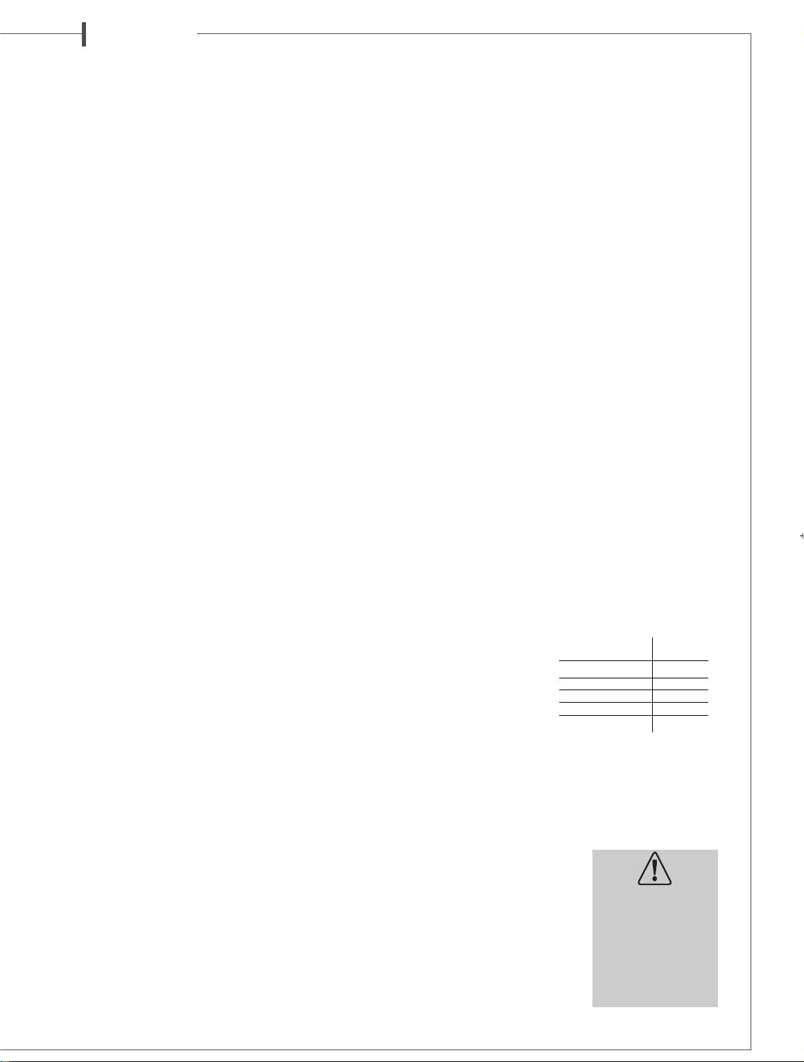
Abstand Querschnitt
Verstärker/Box
4,5 m 1,5 mm
2
6 m 2 mm
2
7,5 m 2,5 mm
2
9 m 3 mm
2
12 m 4 mm
2
Achtung, bevor Sie Ihre
Anlage an das Stromnetz
anschließen,
müssen Sie sicherstellen,
dass die Netzspannung der
auf dem Schalter
AC voltage
selector 115V - 230 V
r
der angegebenen Spannung
entspricht.
Page 14
d e u t s c h
AUFSTELLUNG IN DER KONFIGURATION
5.1 MIT AKTIVEM SUBWOOFER
Aufstellung des aktiven Subwoofers
Eigentlich brauchen Subwoofer nicht an ganz bestimmten Stellen innerhalb der Hörzone aufgestellt zu werden, wenn die
Trennfrequenz der Weiche um 150 Hz liegt. Unter dieser Frequenz hat der Lautsprecher keine Richtungsfunktion mehr,
und man kann nicht hören, aus welcher Richtung die Basstöne kommen. Für optimale Ergebnisse sollten Versuche an verschiedenen Stellplätzen vorgenommen werden, um in Abhängigkeit von der Raumakustik bei Tieffrequenzen die besten
Effekte zu erzielen.
Anschliessen des aktiven Subwoofers
Die Eingangssignalsanschlüsse können auf zwei verschiedene
Weisen vorgenommen werden :
■ entweder mit abgeschirmten Koaxialkabeln an den
Cinch
RCA LINE IN
7
und
LINE OUT8Ein- und Ausgängen,
■ oder mit dem herkömmlichen Lautsprecherkabel an den
HIGH LEVEL INPUT9und
HIGH LEVEL OUTPUT0Laut -
sprecheranschlüssen.
Die Eingänge sind stereophonisch, linke
L (left)
und rechte
R
(right)
Tieftöne werden im Verstärker gemischt. Falls ein MonoSignal am Subwoofer anliegen sollte, darf nur einer der Eingänge
L (left)
oder
R (right)
benutzt werden.
Anschluss über die Cinch RCA Buchsen
■ LINE IN
7
Buchsen
Wenn Ihr Vorverstärker oder der Verstärker Ihrer Audio/Video anlage einen Vorverstärker Stereo-Ausgang besitzt, müssen die
linken
L (left)
und rechten
R (right)
Ausgänge des Verstärkers
oder Vorverstärkers mit den linken
L (left)
und rechten
R (right)
LINE IN
7
Eingängen des Subwoofers verbunden werden.
Wenn Ihre Anlage nur über einen einzigen Monoausgang verfügt
(Subwoofer/LFE), muss dieser entweder mit dem linken
L (left)
oder rechten
R (right) LINE IN7Eingang verbunden werden.
■ LINE OUT
8
Buchsen
Die linken
L (left)
und rechten
R (right) LINE OUT8Anschlüs-
se geben die am
LINE IN7Eingang ankommende NF-
Signale wieder. An diesen
LINE OUT8Ausgängen kann der
Verstärker der Hauptlautsprecher angeschlossen werden.
Zusammenschaltung mit
den Lautsprecher-Anschlüssen
■ HIGH LEVEL INPUT
9
Anschlüsse
Wenn Ihr Vollverstärker keinen NF-Ausgang besitzt, müssen
die Ausgänge des Verstärkers an die linken
L (left)
und rechten
R (right) HIGH LEVEL INPUT9Anschlüsse des Subwoofers
angeschlossen werden. Sie können den Subwoofer an die für
Lautsprecher bestimmten Anschlüsse Ihres Verstärkers
anschließen. Wenn Sie die linken und rechten Ausgänge Ihres
Verstärkers an die linken und rechten Eingänge des Subwoofers
anschließen, dürfen Sie die Phasen (+ und - oder Rot und
Schwarz) der Kabel nicht vertauschen, sonst riskieren Sie eine
Panne des Haupt/Vollverstärkers.
■ HIGH LEVEL OUTPUT
0
Anschlüsse
Diese Anschlüsse geben das gleiche Signal wieder wie das an
die
HIGH LEVEL INPUT9Eingänge und erlauben zum Beispiel
einen Anschluss der Hauptlautsprecher.
Netzanschluss
Der Stecker-dient zum Anschluss des Subwoofers. Die Netz spannung wird mit Hilfe des Schalters
115V- 230V=eingestellt.
Zum Einschalten wird der Schalter
POWERqauf
standby
oder ongestellt.
In der Position
standby
geht das Gerät automatisch in den
Standby-Modus, wenn einige Minuten lang kein Signal empfangen wird. Bei Eintritt eines Signals schaltet sich der Subwoofer automatisch wieder ein.
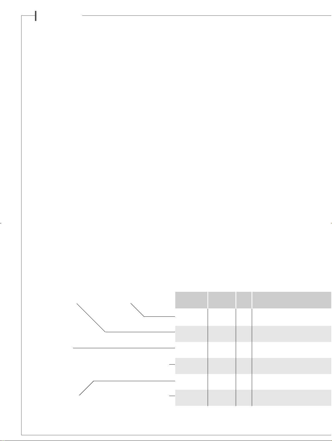
MC40 Verwendung Wege Chassis
W
MINORCA Regal 3 1 x 2-Wege Koaxial-Chassis BC10
Haupt 1 x 17 cm (7”) 17MD18LB1
JAVA Standbox 3 1 x 2-Wege Koaxial-Chassis BC10
Haupt 2 x 17 cm (7”) 17MD18LB1
MAJORCA Standbox 3 1 x 2-Wege Koaxial-Chassis BC10
Haupt 2 x 21 cm (8”) 21MD18LB1
CABRERA auf/unter 3 1 x 2-Wege Koaxial-Chassis BC10
Center* Shirm 2 x 17 cm (7”) 17MD18LB1TV
FORMENTERA
Regal/ 3 1 x 2-Wege Koaxial-Chassis BC10
Surround Wand 1 x 17 cm (7”) 17MD18LB1
MERCURE Standbox 11x21 cm (8”) 21MT4
Aktiv Subwoofer
TECHNISCHE DATEN
* Magnetische Abschirmung
Page 15
d e u t s c h
Einstellungen
■ LEVEL
w
Bei einer ersten Einstellung der Lautstärke regeln Sie den
CROSSOVER FREQUENCYeauf ungefähr 120 Hz, dann
stellen Sie die Lautstärke
LEVELwhöher, bis Sie die gewünschte
Tieftonstärke erreicht haben. Nach Einstellung der gewünschten Frequenz am
CROSSOVER FREQUENCYeund der
ge wünschten Pha se am
PHASErSchalter, müssen Sie
wahrscheinlich erneut die Lautstärke am Schalter
LEVEL
w
einstellen.
■ CROSSOVER FREQUENCY
e
Dieser Potentiometer dient zur Einstellung der oberen Frequenzen der Tonwiedergabe des Subwoofers. Die Einstellung
hängt von den Hauptlautsprechern ab, die mit dem Subwoofer
eingesetzt werden und von ihrer Funktionsweise im Raum. Die
beste Übergangsfrequenz ermitteln Sie mit Hilfe von Versuchen.
■
PHASE
r
Je nachdem, wie der Subwoofer den Satellitenlautsprechern
gegenüber positioniert ist, kann es vorkommen, dass die Phase des Subwoofer für eine bessere Tonqualität umgekehrt werden muss. Hierfür muss der Schalter von 0° auf 180° verstellt
werden. Je nach Einstellung des
CROSSOVER FREQUENCY
e
Potentiometers müssen Sie selbst entscheiden, welche Phase die
beste ist. Achtung, wenn Sie einen zweiten Subwoofer einsetzen, muss dort der Phasenumschalter in der gleichen Position
stehen wie auf dem ersten Subwoofer.
Auf unserer Homepage können Sie die spezifischen Einstellungen ersehen, die wir für unsere Subwoofer empfehlen.
www.cabasse.com
PFLEGE
Gehäuse der Serien MC40 sind mit hochwertigem Kunststoff
Material furniert. Sie sind dank zweier Lackschichten und mit
einer zusätzlichen Schicht gegen Kratzer geschützt und können
mit einem feuchten Tuch abgerieben werden.
Wenn Sie unseren Aufbau- und Verkabelungs-Empfehlungen
folgen und Sie sich nach der Bedienungsanleitung orientieren,
ist ein perfektes Funktionieren Ihres Systems gesichert.
Zufriedene Kunden schreiben uns jeden Tag, und das ist für uns
die schönste Belohnung.
Für hohe Zuverlässigkeit und optimale Qualität entwickelt Cabasse seine Geräte permanent weiter und behält sich deshalb das Recht vor,
an den auf technischen Unterlagen oder Werbematerial gezeigten Modellen Änderungen vorzunehmen.
Wirkungsgrad
Überganz- Übertragungs-
Nenn Impedanz Nenn- Spitzen- Gehäuse Abmessungen Gewicht
1W/1m bereich bereich Impedanz Minimum belastung belastung Aussführungen H
xBx
T (kg)
(dB) (Hz) (Hz) (ohms) (ohms) (Watt) (Watt) (cm)
x 23 x28 9,5
x 25 x35 27
x 29 x35 31
x 49 x 35 12
x 32 x15 8
x 36 x45 22
Naturkirsche-Dekor beigen
+ schwarzfarbenenRahmen
Mahagony-Dekor beigen
schwarzfarbenen Rahmen
Naturkirsche-Dekor beigen
+ schwarzfarbenenRahmen
Mahagony-Dekor beigen
schwarzfarbenen Rahmen
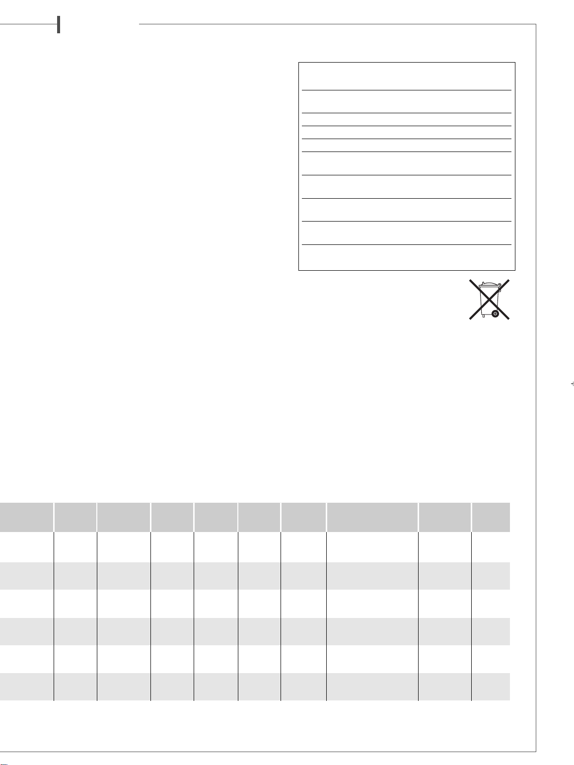
Naturkirsche-Dekor beigen
+ schwarzfarbenenRahmen
Mahagony-Dekor beigen
schwarzfarbenen Rahmen
Naturkirsche-Dekor beigen
+ schwarzfarbenenRahmen
Mahagony-Dekor beigen
schwarzfarbenen Rahmen
Naturkirsche-Dekor beigen
+ schwarzfarbenenRahmen
Mahagony-Dekor beigen
schwarzfarbenen Rahmen
Naturkirsche-Dekor
Mahagony-Dekor
WEEE KENNZEICHNUNG
Behandlung der Elektro- und
Elektronik-Altgeräte (Verwendbar
in die Europaïsche Union)
Dieses Symbol, das eine durchgestrichene Abfalltonne auf
Rädern darstellt, ist auf dem Produkt angebracht und bedeutet, dass dieses Produkt nicht als unsortierten Siedlungsabfall
zu beseitigen ist.
Es muss in eine Sammlungspunkt für die Behandlung von
Elektro- und Elektronik-Altgeräte eingerichtet sein.
Versichernd, dass dieses Produkt auf geeignete Weise beseitigt ist, Sie werden helfen, die potentiellen negativen Folgen
für die Umwelt und die Humangesundheit vorzubeugen.
Recycling von Baustoffe wird helfen, die Bodenschätzen zu
bewahren. Für jede zusätzliche Information bezüglich des
Recyclings dieses Produktes können Sie mit Ihrer
Stadtverwaltung, Ihrer öffentliche Rücknamestelle oder dem
Geschäft kontaktieren, wo Sie das Produkt gekauft haben.
AK TIV SUBWOOFER MERCURE MC40
Max. Schalldruck 114dB
Phasenschalter 0° normale Phase
180° umgekehrte Phase
Signaleingänge 2 tief - 2 hoch
Stromversorgung 115/ 230V AC-50/60Hz
Max. Leistungsaufnahme 165 W
Standby Stromverbrauch 0,49W @ 230VAC
0,5W @ 115VAC
Stromverbrauch Off-Modus 0,04W @ 230VAC
0,04W @ 115VAC
Zulässige Umgebungstemperatur
für Betrieb von +5°C bis +35°C
Zulässige Umgebungstemperatur
für Lagerung von -5°C bis +40°C
Zulässige Luftfeuchtigkeit
für Betrieb von 40% bis 70%
Page 16
Cabasse SA - 210, rue René Descartes - BP 10 - 29280 Plouzané
Tel +33 (0)2 98 05 88 88 - Fax +33 (0)2 98 05 88 99
www.cabasse.com
NOT0276 - 09/11 Crédit photos : GPO
 Loading...