

Page 1

S070
RACCORD-CAPTEUR INLINE A ROUES OVALES
INLINE POSITIVE DISPLACEMENT FLOW FITTING-SENSOR
INLINE DURCHFLUSS FITTING-SENSOR MIT OVALRÄDERN
Consignes de sécurité
Les travaux de
montage et/ou de
maintenance doivent
être réalisés par un
personnel qualifié.
En cas de difficultés
lors de l‘installation,
veuillez contacter votre
fournisseur Bürkert.
- Veillez toujours à la
compatibilité chimique
des matériaux en
contact avec le fluide.
- Pour le nettoyage du
raccord, utilisez des
produits chimiquement
compatibles avec les
matériaux du raccord.
- Lors du démontage
du capteur de la
conduite, prenez
toutes les précautions
liées au procédé.
Utilisation
Ce raccord est destiné à la
mesure du débit de liquides,
particulièrement les liquides
visqueux (max. 1000cps) en
combinaison avec les transmetteurs / détecteurs à seuil type
SE30, SE35, SE32, SE36.
Safety instructions
The fitting should only
be installed and repaired by specialist staff.
If any difficulties may
occur with the product
during ins tal la tion,
please contact your
nearest Bürkert sales
office for assistance.
- Always ensure the
materials in contact
with the medium are
chemically com pa ti ble.
- To clean the device,
only use chemically
compatible products.
- When dismounting
the device from the
pipe, take all the
precautions linked to
the process.
Utilisation
This flow fitting has been designed for all liquid flow measurements especially viscous fluids
(max. 1000cps) in combination
with our transmitters / threshold
detectors type SE30, SE35,
SE32, SE36.
Sicherheitsmaßnahmen
Einbau und/oder
Reparatur dürfen nur
durch eingewiesenes
Personal erfolgen. Sollten bei der Installation
oder der Inbetriebnahme Schwierigkeiten
auftreten, setzen Sie
sich bitte mit Bürkert in
Verbindung.
- Beachten Sie bei
speziellen Messmedien,
inkl. Medien für die
Reinigung, die
Materialbeständigkeit
von mediumberührenden
Teilen.
- Dem verwendeten
Prozess entsprechend
müssen geeignete
Vorsichtsmaßnahmen
getroffen werden,
bevor der Fitting
ausgebaut wird.
Verwendung
Dieser Fitting wurde zur
Durchflussmessung von allen
Flüssigkeiten, besonders viskose
Medien (max. 1000cps), in Kombination mit den Transmittern /
Schwellen-Detektoren Typ SE30,
SE35, SE32, SE36 entwickelt.
Sous réserve de mo di fi ca tions techniques / Subject to technical change without notice /
Technische Änderung vorbehalten
© Bürkert 2002_2013
1
Page 2
S070
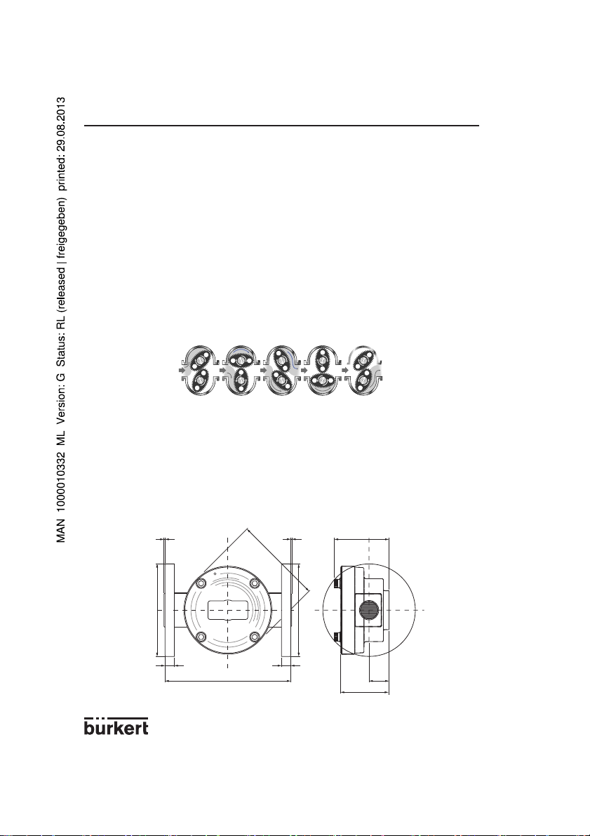
Description et principe de
mesure
La conception de ce raccord
repose sur des roues ovales,
principe fiable et très précis de
mesure de débit volumétrique.
Ce concept permet une excellente répétabilité et précision sur
une plage de débit et de viscosité très étendue. La faible perte
de charge et la bonne tenue en
pression permet une utilisation
dans des applications diverses:
écoulement gravitaire ou en ligne
(pompe).
Tous les raccords sont compatibles avec les modules électroniques types SE30, SE35, SE36
et SE32 équipés de capteurs à
effet Hall.
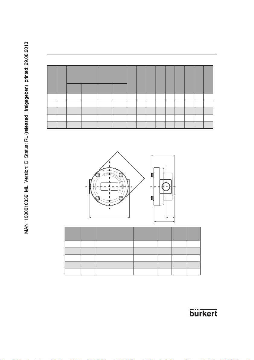
Dimensions
J
Description and measuring
principle
The design of this fitting is based
on the oval rotor principle. This
has proven to be a reliable
and highly accurate volumetric method of measuring flow.
Exceptional repeatability and
high accuracy over a wide range
of viscosities and flowrates are
features of that design. The low
pressure drop and high pressure rating makes it suitable for
both gravity and pump (in-line)
applications.
All fittings are compatible with
the electronic modules types
SE30, SE35, SE36 and SE32
with Hall sensor principle.
Dimensions
K
A
Beschreibung und
Messprinzip
Dieser Fitting wurde nach dem
Ovalrad Messprinzip entwickelt.
Dieses, seit Jahren erprobte Prinzip, ermöglicht sehr genaue und
wiederholbare Messungen über
einen großen Durchfluss- und
Viskositäts-Bereich. Ein niedriger
Druckverlust und eine hohe
Druckfestigkeit erlauben einen
Einsatz in den verschiedesten
Applikationen: gravimetrischer
Durchfluss oder über Pum pen.
Alle Fittings sind mit den Elektronik Modulen, Typen SE30, SE35,
SE36 und SE32 mit Hall Sensor,
kompatibel.
Abmessungen
C
G
ANSI Flansch
E
DIN Flansch
FH
BD
L
2
Page 3
S070
DN A B
25 112 291 294 281 284 91 35 115 16 108 16.0 1.6 1.6 85
40 144 262 270 262 270 120 45 150 16 127 17.5 1.6 1.6 112
50 178 264 264 264 264 150 55 165 18 152 19.0 1.6 1.6 140
80 220 344 348 436 436 212 77 200 22 191 22.5 1.6 1.6 202
100 291 382 390 578 578 230 108 220 22 229 22.5 1.6 1.6 234
Stainless steel /
Acier inoxydable
/ Edelstahl
DIN ANSI DIN ANSI
DN A B
15 96 100 100 61 20 55
25 112 143 133 91 35 85
40 144 124 124 120 45 112
50 178 210 210 150 55 140
80 220 260 260 212 77 202
B
Aluminium
BD
Stainless steel / Acier
inoxydable / Edelstahl
CDEFGHJ KL
C
A
E
B
Aluminium
CDE
3
Page 4
S070
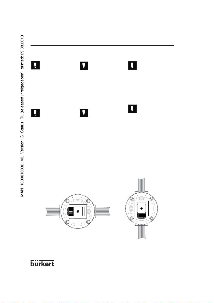
Installation et montage
Le raccord tolère des
tailles de particule
jusqu‘à 250 µm. Pour
éviter tout dommage
dû à des particules,
nous recommandons
l‘installation d‘un filtre
250 µm en amont et
aussi près que possible du capteur.
La canalisation doit
être remplie et exempte de bulles d‘air. Eviter
des purges à l‘air.
- Utiliser un produit d‘étanchéité
pour filetage.
- Installer le raccord de sorte que
les axes des roues soient dans
un plan horizontal. Le sens du
débit est indiqué par une flêche
sur le corps.
Installation and mounting
The fitting can handle
particle sizes up to
250 µm. To prevent
damage from dirt or
foreign matter, we
strongly recommend
the installation of a
250 µm (60 mesh)
strainer as close as
possible to the inlet
side of the sensor.
The pipe must be
filled with liquid and
free from air bubbles.
Avoid air purge of the
system.
- Use thread sealant on all pipe
threads.
- Ensure the fitting is installed so
that rotor shafts are always in a
horizontal plane. Flow direction is
marked by an arrow on the body.
Correct
Richtig
Aufbau
Der Fitting verträgt
Partikeln bis zu einer
Größe von 250 µm.
Um Schaden durch
Partikeln zu verhindern,
empfehlen wir den
Einbau eines 250 µm
Filters so nah wie möglich am Sensoreingang.
Die Rohrleitung muss
voll mit Medium und
Luftfrei sein. Reinigung
mit Druckluft verhindern.
- Gewinde mit Dichtwerkstoff gut
abdichten.
- Fitting so montieren, dass die
Achsen waagerecht liegen.
Durchflussrichtung ist durch ein
Pfeil am Gehäuse gekennzeichnet.
4
Page 5

W
A
R
N
I
N
G
/
D
O
N
O
T
R
E
M
O
V
E
T
H
I
S
C
O
F
L
O
W
Incorrect
Nicht richtig
S070
Caractéristiques techniques
DN des conduites
DN15 à 100
Raccord process
Taraudage G ou NPT 1/2’’, 1’’,
1 1/2’’, 2'', 3''
Brides 25, 40, 50, 80, 100 mm
DIN 16
Brides ANSI 150lb 1'', 1 1/2’’,
2’’, 3'', 4''
Plage de débit
Viscosité > 5 cps
2 à 1200 l/min.
Viscosité < 5 cps
3 à 616 l/min.
Précision
+/-0.5% de la valeur mesurée
Max. viscosité
1000 cps, plus sur de man de
Technical data
Pipe diameter
DN15 to 100
Process connection
Thread G or NPT1/2’’, 1’’,
1 1/2’’, 2'', 3''
Flanges 25, 40, 50, 80, 100 mm
DIN 16
Flanges ANSI 150lb 1'', 1 1/2’’,
2’’, 3'', 4''
Flow rate range
Viscosity > 5 cps
2 to 1200 l/min.
(0.26 to 320 gpm)
Viscosity < 5 cps
3 à 616 l/min.
(0.78 to 160 gpm)
Accuracy
+/-0.5% of reading
Max. viscosity
1000 cps, higher on request
5
Technische Daten
Rohrdurchmesser
DN15 bis 100
Prozessanschluss
Gewinde G oder NPT1/2’’, 1’’,
1 1/2’’, 2'', 3''
Flansch 25, 40, 50, 80, 100 mm
DIN 16
Flansch ANSI 150lb 1'', 1 1/2’’,
2’’, 3'', 4''
Durchflussbereich
Viskosität > 5 cps
2 bis1200 l/min
Viskosität < 5 cps
3 bis 616 l/min.
Genauigkeit
+/-0.5% vom Messwert
Max. Viskosität
1000 cps, höhere auf Anfrage
Page 6

S070
Caractéristiques techniques
Taille max. de particule
250 µm
Facteur K
1/2’’: 112 impulsions/l
1’’: 36 impulsions/l
1 1/2’’: 14.5 impulsions/l
2’’: 6.68 impulsions/l
3’’: 2.59 impulsions/l
4’’: 2.315 impulsions/l
Pression du fluide max.
Corps aluminium et acier inoxydable: 55 bar (800 psi)
Version brides: 10 bar (14 psi)
Température fluide max.
Corps Al: 80°C
Corps inox: 120°C
Température ambiante max.
0-60°C (32-140°F)
Matériaux
- Corps: Aluminium ou acier
inoxydable 316 (1.4401)
- Roues: PPS ou acier
inoxydable 316 (1.4401)
- Paliers : acier inoxydable
- Joints: FKM ou FEP/PTFE
Poids
600g
Indice de protection
IP66 (NEMA 6)
(suite)
Technical data
(continued)
Max. particle size
250 µm
K-factor
1/2’’: 112 pulse/l
1’’: 36 pulse/l
1 1/2’’: 14.5 pulse/l
2’’: 6.68 pulse/l
3’’: 2.59 pulse/l
4’’: 2.315 pulse/l
Max. fluid pressure
Aluminium and SSt body:
55 bar (800 psi)
Flange version: 10 bar (14 psi)
Max. fluid temperature
Al body: 80°C (176°F)
SSt body: 120°C (248°F)
Max. ambient temperature
0-60°C (32-140°F)
Materials
- Body: Aluminium or stainless
steel 316 (1.4401)
- Rotors: Aluminium or
stainless steel 316 (1.4401)
- Shaft : stainless steel
- Gasket: FKM or FEP/PTFE
Weight
600g
Protection rating
IP66 (NEMA 6)
Technische Daten
(Fortsetzung)
Max. Partikelgröße
250 µm
K-Faktor
1/2’’: 112 Puls/l
1’’: 36 Puls/l
1 1/2’’: 14.5 Puls/l
2’’: 6.68 Puls/l
3’’: 2.59 Puls/l
4’’: 2.315 Puls/l
Max. Flüssigkeitsdruck
Aluminium- und EdelstahlGehäuse: 55 bar (800 psi)
Flansch Ausf.: 10 bar (14 psi)
Mediumstemperatur max.
Aluminium-Gehäuse: 80°C
Edelstahl-Gehäuse: 120°C
Raumtemperatur max.
0-60°C (32-140°F)
Werkstoffe
- Gehäuse: Aluminium oder
Edelstahl (1.4401)
- Ovalräder: PPS oder Edelstahl
(1.4401)
- Lager : Edelstahl
- O-Ring: FKM oder FEP/PTFE)
Gewicht
600g
Schutzklasse
IP66 (NEMA 6)
Maintenance
Démontage
1- Vérifier que la conduite n‘est
plus sous pression.
2- Désserrer les 4 vis et retirer le
couvercle.
3- Retirer le joint et vérifier l‘as
pect; remplacer si nécessaire.
Maintenance
Disassembly
1- Ensure the fluid supply to the
meter has been disconnected,
and the line pressure has been
released.
2- Remove four screws and
meter cover.
3- Remove o-ring and inspect;
replace if damaged.
6
Wartung
Ausbau
1- Sicherstellen, dass die
Leitung nicht mehr unter Druck
ist.
2- Die 4 Schrauben lösen und
Deckel abnehmen.
3- Dichtung entfernen und un
tersuchen; wenn nötig
auswechseln.
Page 7

S070
4- Retirer les roues, vérifier et
nettoyer; remplacer si nécessaire.
Remontage
1- Replacer les roues dans le
boîtier. Elles doivent être à 90°
l‘une de l‘autre.
Les roues doivent être
replacées avec les
aimants vers le haut
(voir schéma).
2- Tourner doucement les roues
avec le doigt; elles doivent
tourner librement.
3- Replacer le joint.
4- Remettre le couvercle.
La rainure du couvercle doit être alignée
avec celle du boîtier
(voir schéma).
5- Resserrer les 4 vis en croix
avec le couple de serrage
approprié :
DN
15
25
40
50
4- Remove rotors, clean and
inspect; replace if damaged.
Reassembly
1- Replace rotors into the meter
body. The rotors should be at
90° to each other.
The rotor must be
placed in the body with
the magnets on the top
(see picture).
2- Lightly rotate the rotors by
hand; they must turn freely.
3- Install o-ring.
4- Replace the meter cap.
The groove on the
cover must line up with
the groove on the body
(see picture).
5- Replace four screws and
fasten in an alternating pattern
at the appropriate torque
rating:
Matériau du corps
Body material
Gehäuse-Werkstoff
Aluminium 3,5 Nm
Acier inoxydable
Stainless steel
Edelstahl
Aluminium 8,5 Nm
Acier inoxydable
Stainless steel
Edelstahl
Aluminium 17 Nm
Acier inoxydable
Stainless steel
Edelstahl
Couple de serrage
Torque rating
Drehmoment
9 Nm
22 Nm
44 Nm
4- Ovalräder entfernen, reinigen
und untersuchen; wenn nötig
auswechseln.
Aufbau
1- Ovalräder in Gehäuse ein
legen. Die Räder müssen um
90° verdreht sein.
Die Räder müssen so
eingelegt werden, dass
die Magnete auf der
oberen Seite liegen
(siehe Zeichnung).
2- Leicht per Hand die Räder
drehen; sie müssen sich
reibungslos bewegen.
3- O-Ring zurückeinlegen.
4- Deckel wieder auflegen.
Die Nut des Deckels
muss mit der Nut des
Gehäuses gleich liegen
(siehe Zeichnung).
5- Schrauben wieder über Kreuz
mit dem geeigneten Drehmo
ment festziehen.
Serrer avec précaution
de sorte à ne pas endommager le boîtier.
Care must be taken
not to overtighten the
screws or damage may
occur to the body.
7
Schrauben nicht zu
fest anziehen, das
Gehäuse könnte beschädigt werden.
Page 8

S070
Références de commande
des produits finis
443985
443990
FEP/
Stainless steel
2 - 30 l/min 3 - 25 l/min Aluminium PPS FKM
G 1/2''
443995
PTFE
Edelstahl
Stainless steel
Acier inoxydable
2 - 30 l/min 3 - 25 l/min
2 - 30 l/min 3 - 25 l/min Aluminium PPS FKM
15
FEP/
NPT 1/2''
Bestell-Nr
commande
Order code
Référence de
Joint
Gasket
Dichtung
Matériau roue
Rotor material
Räder-Werkstoff
Body material
Matériau boîtier
Gehäuse-Werkstoff
Messbereich
Plage de débit
< 5 cps (l/min)
Flow rate range
Messbereich
Plage de débit
> 5 cps (l/min)
Flow rate range
Prozess Anschluss
Process connection
Raccordement process
DN
444000
443986
PTFE
Edelstahl
Stainless steel
Acier inoxydable
Aluminium PPS FKM
2 - 30 l/min 3 - 25 l/min
Order codes,
finished products
PTFE
Edelstahl
443996
FEP/
Stainless steel
Aluminium PPS FKM
NPT 1'' 6 - 120 l/min 10 - 100 l/min
444001
PTFE
Acier inoxydable
443991
FEP/
Acier inoxydable
G 1'' 6 - 120 l/min 10 - 100 l/min
553634
553637
FEP/
PTFE
Edelstahl
Stainless steel
Acier inoxydable
Aluminium PPS FKM
6 - 120 l/min 10 - 100 l/min
25 mm DIN16 flanges
Brides DIN 16 25 mm
25 mm DIN16 Anschluss-
25
553633
553636
FEP/
PTFE
Edelstahl
Stainless steel
Acier inoxydable
Aluminium PPS FKM
6 - 120 l/min 10 - 100 l/min
schellen
schellen
1'' ANSI 150LB flanges
Brides ANSI 150 LB 1''
1'' ANSI 150LB Anschluss-
Bestell-Nummern
der S030 Fittings
443992
443987
Edelstahl
Aluminium PPS FKM
FEP/
PTFE
Edelstahl
Stainless steel
Acier inoxydable
G 1 1/2'' 10 - 250 l/min 15 - 235 l/min
40
443997
PPS FKM
Aluminium
444002
FEP/
PTFE
Edelstahl
Stainless steel
Acier inoxydable
NPT 1 1/2'' 10 - 250 l/min 15 - 235 l/min
8
Page 9

S070
Références de commande
des produits finis
(suite)
443993
FEP/
PTFE
Edelstahl
Stainless steel
Acier inoxydable
10 - 250 l/min 15 - 235 l/min
443998
Stainless steel
Aluminium PPS FKM
Bestell-Nr
commande
Order code
Référence de
Joint
Gasket
Dichtung
Matériau roue
Rotor material
Räder-Werkstoff
Body material
Matériau boîtier
Gehäuse-Werkstoff
Messbereich
Plage de débit
< 5 cps (l/min)
Flow rate range
Messbereich
Plage de débit
> 5 cps (l/min)
Flow rate range
443988
Aluminium PPS FKM
444003
553640
FEP/
PTFE
Edelstahl
Acier inoxydable
10 - 250 l/min 15 - 235 l/min
Order codes,
finished products
(cont'd)
443994
443989
FEP/
Stainless steel
Aluminium PPS FKM
15 - 350 l/min 30 - 300 l/min
443999
PTFE
Edelstahl
Acier inoxydable
Aluminium PPS FKM
553641
444004
553642
FEP/
PTFE
Edelstahl
Stainless steel
Acier inoxydable
15 - 350 l/min 30 - 300 l/min
553643
553645
20 - 733 l/min 66 - 616 l/min Aluminium FKM
Bestell-Nummern
der S030 Fittings
(Fortsetzung)
553644
553647
20 - 733 l/min 66 - 616 l/min Aluminium FKM
120 - 1200 l/min --- Aluminium FKM
553646
--- Aluminium FKM
120 - 1200 l/min
Prozess Anschluss
Process connection
Brides DIN 16 40 mm
Raccordement process
DN
G 2'' 15 - 350 l/min 30 - 300 l/min Aluminium PPS FKM
40 mm DIN16 flanges
1 1/2'' ANSI 150LB flanges
Brides ANSI 150 LB 1 1/2''
40 mm DIN16 Anschluss-schellen
1 1/2'' ANSI 150LB Anschluss-schellen
40
NPT 2'' 15 - 350 l/min 30 - 300 l/min Aluminium PPS FKM
50 mm DIN16 flanges
Brides DIN 16 50 mm
50 mm DIN16 Anschluss-schellen
50
9
G 3'' 20 - 733 l/min 66 - 616 l/min Aluminium FKM
NPT 3'' 20 - 733 l/min 66 - 616 l/min Aluminium FKM
80 mm DIN16 flanges
2'' ANSI 150LB flanges
Brides ANSI 150 LB 2''
Brides DIN 16 80 mm
2'' ANSI 150LB Anschluss-schellen
80
rides ANSI 150 LB 3''
3'' ANSI 150LB flanges
80 mm DIN16 Anschluss-schellen
rides ANSI 150 LB 4''
100 mm DIN16 flanges
Brides DIN 16 100 mm
4'' ANSI 150LB flanges
100 mm DIN16 Anschluss-schellen
3'' ANSI 150LB Anschluss-schellen
100
4'' ANSI 150LB Anschluss-schellen
Page 10

S070
Références de commande
des pièces de rechange
Désignation
Description
Bezeichnung
Roues
Rotor
Ovalräder
Joint
Gasket
O-ring
Diamètre / Diameter / Durchmesser Matériau
[mm] [pouce / inch / Zoll]
DN15 1/2''
DN25 1''
DN40 1 1/2''
DN50 2''
DN15 1/2''
DN25 1''
DN40 1 1/2''
DN50 2''
Order codes,
spare parts
Material
Werkstoff
PPS
Stainless steel
Acier inoxydable
Edelstahl
PPS
Stainless steel
Acier inoxydable
Edelstahl
PPS
Stainless steel
Acier inoxydable
Edelstahl
PPS
Stainless steel
Acier inoxydable
Edelstahl
FEP/PTFE
FKM
FEP/PTFE
FKM
FEP/PTFE
FKM
FEP/PTFE
FKM
Bestell-Nummern
der Ersatzteile
Référence de commande
Order code
Bestell-Nr
550933
550934
550937
550938
550941
550942
550945
550946
550929
550930
550935
550936
550939
550940
550943
550944
10
Page 11

Trouble
Fluid will not flow through the meter
Reduced flow through the meter
Meter reading inaccurate
Meter not giving a pulse signal
Problème
Le fluide ne s‘écoule plus à travers le
capteur
Débit réduit à travers le capteur
Mesure incohérente
Pas de sortie impulsion
Problem
Kein Durchfluss durch den Sensor
Reduzierter Durchfluss durch den Sensor
Messung ungenau
Kein Pulsausgang
Trouble shooting guide
Cause
A- Foreign matter blocking
B- Line strainer blocked
C- Damaged rotors
A- Line strainer partially blocked
B- Fluid too viscous
A- Fluid flowrate out of specifications
B- Air in fluid
C- Excess wear caused by incorrect meter
assembly
A- Faulty Hall sensor
B- Faulty magnet
C- Rotors installed in wrong position
Résolution de panne
Cause
A- Capteur obturé
B- Filtre obturé
C- Roues endommagées
A- Filtre partiellement obturé
B- Fluide trop visqueux
A- Plage de débit du capteur inadaptée
B- Air dans la conduite
C- Frictions dues à un mauvais remontage
du capteur
A- Capteur Hall défectueux
B- Aimant défectueux
C- Roues montées dans le mauvais sens
Fehlerbehebung
Ursache
A- Fremdkörper eingeklemmt
B- Filter verstopft
C- Räder beschädigt
A- Filter teilweise verstopft
B- Medium zu viskos
A- Durchfluss außerhalb des Messbereichs
B- Luft in der Leitung
C- Reibung durch schlechten
Zusammenbau des Sensors
A- Defekter Hall-Sensor
B- Defekte Magnete
C- Räder in falscher Position eingebaut
S070
Remedy
A- Dismantle meter, clean rotors (strainer
must be fitted in line)
B- Clean strainer
C- Change rotors
A- Clean strainer
B- Maximum 1000 cps, change to high
viscosity rotors
A- Check specifications, adapt meter size
or flowrate
B- Bleed air from system
C- Check meter body and rotors
A- Replace meter cap
B- Change rotors
C- Refer to correct rotor positioning
Solution
A- Démonter et nettoyer les roues (rajouter
filtre adapté en amont)
B- Nettoyer le filtre
C- Changer les roues
A- Nettoyer le filtre
B- Maximum 1000 cps, prendre des roues
haute viscosité
A- Vérifier spécifications, adapter capteur
ou débit
B- Purger l‘air de la conduite
C- Vérifier l‘assemblage du capteur et des
roues
A- Remplacer le couvercle
B- Remplacer les roues
C- Démonter le capteur et changer la
position des roues
Lösung
A- Sensor ausbauen und Räder reinigen
(angepasster Filter einbauen)
B- Filter reinigen
C- Räder auswechseln
A- Filter reinigen
B- Maximum 1000 cps, auf hochviskose
Räder umschalten
A- Sensor oder Durchfluss anpassen
B- Luft ablassen
C- Montage des Gehäuses und der Räder
überprüfen
A- Deckel auswechseln
B- Räder auswechseln
C- Sensor ausbauen und Räder richtig
positionieren
11
Page 12

S070
Europe
AUSTRIA
Phone: +43 (0)1-894 13 33
Fax: +43 (0)1-894 13 00
E-mail: info@buerkert.at
BELGIUM
Phone: +32 (0)3-325 89 00
Fax: +32 (0)3-325 61 61
E-mail: info@burkert.nl
CZECH REP.
Phone: +420 543-25 25 05
Fax: +420 543-25 25 06
E-mail: obchod@buerkert.cz
DENMARK
Phone: +45 44-50 75 00
Fax: +45 44-50 75 75
E-mail: info.dk@burkert.com
FINLAND
Phone: +358 (0)207 412 550
Fax: +358 (0)207 412 555
E-mail: sales.fi@burkert.com
FRANCE
Phone: +33 (0)388-58 91 11
Fax: +33 (0)388-57 20 08
E-mail: burkert.france@buerkert.com
ITALY
Phone: +39 02-959 071
Fax: +39 02-959 07 251
E-mail: info@buerkert.it
NORWAY
Phone: +47 63-84 44 10
Fax: +47 63-84 44 55
E-mail: buerkert@burkert.no
NETHERLANDS
Phone: +31 (0)88 12 67 300
Fax: +31 (0)88 12 67 350
E-mail: info@burkert.nl
PORTUGAL
Phone: +351 212 898 275
Fax: +351 212 898 276
E-mail: portugal@burkert.com
POLAND
Phone: +48 (0)22-840 60 10
Fax: +48 (0)22-840 60 11
E-mail: buerkert@buerkert.pl
SPAIN
Phone: +34 93-477 79 80
Fax: +34 93-477 79 81
E-mail: spain@burkert.com
SWEDEN
Phone: +46 (0)40-664 51 00
Fax: +46 (0)40-664 51 01
E-mail: info.se@burkert.com
SWITZERLAND
Phone: +41(0)41-785 66 66
Fax: +41(0)41-785 66 33
E-mail: info.ch@buerkert.com
TURKEY
Phone: +90 (0)232-459 53 95
Fax: +90 (0)232-459 76 94
E-mail: info.turkey@buerkert.com
UNITED KINGDOM
Phone: +44 (0)1453-73 13 53
Fax: +44 (0)1453-73 13 43
E-mail: sales.uk@burkert.com
Asia / Oceania
AUSTRALIA
Phone: +61 2 8853 6353
Fax: +61 2 8853 6363
E-mail: sales.au@burkert.com
Victoria
Phone: 1300 888 868
Fax: 1300 888 076
Queensland
Phone: 1300 888 868
Fax: 1300 888 076
Western Australia
Phone: 1300 888 868
Fax: 1300 888 076
South Australia
Phone: 1300 888 868
Fax: 1300 888 076
CHINA
Phone: +86 21-5863 99 90
Fax: +86 21-5863 99 68
E-mail: info.chn@burkert.com
Beijing
Phone: +86 10 64399783
+86 10 64399793
Fax: +86 10 64399612
Chengdu
Phone: +86 28 8425 1434
+86 28 8425 1435
Fax: +86 28 8425 1560
Guangzhou
Phone: +86 20 8769 8379
+86 20 8767 8703
Fax: +86 20 87671131
Shanghai
Phone: +86 21 6486 5110
Fax: +86 21 6487 4815
Suzhou
Phone: +86 512 6265 9881
Fax: +86 512 6265 9882
HONG KONG
Phone: +852 2480 1202
Fax: +852 2418 1945
E-mail: info.hkg@burkert.com
INDIA
Phone: +91 (0)44-4230 3456
Fax: +91 (0)44-4230 3232
E-mail: sales.in@burkert.com
Contact
JAPAN
Phone: +81 (0)3-5804-5020
Fax: +81 (0)3-5804-5021
E-mail: info.jpn@burkert.com
Osaka
Phone: +81 (0)6-6320-0880
Fax: +81 (0)6-6320-0881
KOREA
Phone: +82 (0)2-3462 5592
Fax: +82 (0)2-3462 5594
E-mail: info.kor@burkert.com
MALAYSIA
Phone: +60 (0)4-643 5008
Fax: +60 (0)4-643 7010
E-mail: info.sin@burkert.com
NEW ZEALAND
Phone: +64 (0)9-256 77 77
Fax: +64 (0)9-256 77 47
E-mail: sales.nz@burkert.com
PHILIPPINES
Phone: +63 (0)2-776 43 84
+63 (0)2-776 60 71
Fax: +63 (0)2-776 43 82
E-mail: info.rp@burkert.com
SINGAPORE
Phone: +65 6844 2233
Fax: +65 6844 3532
E-mail: info.sin@burkert.com
TAIWAN
Phone: +886 (0)2-2653 7868
Fax: +886 (0)2-2653 7968
E-mail: info.rc@burkert.com
Africa
SOUTH AFRICA
Phone: +27 (0)11-574 60 00
Fax: +27 (0)11-454 14 77
E-mail: sales.za@burkert.com
America
ARGENTINA
Phone: +54 (0)11-5648-6350
Fax: +54(0)11-5648-6355
E-mail: contacto.argentina@burkert.
com
BRAZIL
Phone: +55 (0)11-2186 1155
Fax: +55 (0)11-2186 1165
E-mail: pedidos.brasil@burkert.com
CANADA
Phone: +1 905-632 30 33
Fax: +1 905-632 38 33
E-mail: sales.ca@burkert.com
USA
Phone: +1 704-504 44 40
Fax: +1 949-223 31 98
E-mail: marketing-usa@burkert.com
12
00448738_1307/1
 Loading...