

Page 1
INSTALLATION MANUAL
ELECTROMAGNETIC FLOWMETER
“FULL BORE” SENSORS
Page 2

SENSOR FOR ELECTROMAGNETIC FLOW METER – MANUAL
INDEX
INTRODUCTION .................................................................................... 3
START UP AND MAINTENANCE OF THE INSTRUMENTS ........................... 3
SAFETY ................................................................................................. 4
GENERAL INFORMATION ON THE SENSORS INSTALLATION .................... 4
OPERATING TEMPERATURES ................................................................. 5
ELECTRICAL CONNECTIONS OF SENSOR TO TRANSMITTER .................... 6
GROUNDING INSTRUCTIONS ................................................................. 7
TORQUES (Nm) FOR SENSOR BOLTS (FLANGED & WAFER) ..................... 8
NOTE FOR 3A APPROVED SENSORS ....................................................... 8
2
ESENS_FULLBORE_05.doc
Page 3

SENSOR FOR ELECTROMAGNETIC FLOW METER – MANUAL
INTRODUCTION
- This manual is integral part of the product. Read carefully the instructions
contained since it contains important indications for the safety of use and
of maintenance.
- The technical information and the relative products of this manual could be
modified without any previous notice.
- The flowmeter must be used for the use it has been built for. The improper
use, possible tampering of the instrument or parts of it and substitutions of
any components not original, makes the warranty to decay automatically.
- The manufacturer is considered responsible only if the instrument is used in
its original configuration and setting.
- The flowmeter makes measures of liquids with conductivity greater than
5µS/cm; it consists of a sensor (described in this manual) and a converter,
for it see the manual provided.
- If the sensor is supplied in compact version to the converter, consider the
operating temperatures more restrictive, otherwise refer to the respective
manuals.
- When transporting, unpacking and handling the flowmeter, be careful and
care.
- In the case of prolonged storage and of transport, use and store in the
original container in a dry place, do not place more than 3 packs one above
the other. It is possible pallets storage and transport (in case of wooden
crates do not place one above the other).
- For the cleaning of the device use only a damp cloth, and for the
maintenance/repairs, contact the customer service.
- For the disposal of the device and of the packaging make strict reference to
the regulations.
- It is forbidden the reproduction of the present manual and of possible
software supplied with the instrument.
START UP AND MAINTENANCE OF THE INSTRUMENTS
- Before starting up the instrument, always make a secure connection to
ground as suitable to page 6.
- Verify periodically: the cables integrity, the tightening of the sealing
elements (cable glands, covers, etc.), the mechanical fixing of the
instrument on the pipe or on the wall.
3
ESENS_FULLBORE_05.doc
Page 4
SENSOR FOR ELECTROMAGNETIC FLOW METER – MANUAL
T
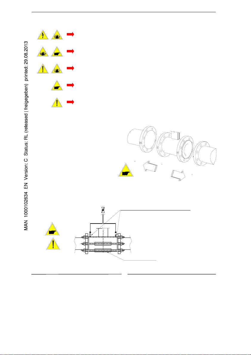
SAFETY
GENERAL INFORMATION ON THE SENSORS INSTALLATION
o
Flow direction
Before installing the sensor checkthe
direction of the liquid in the piping.
The sign of the flow rate is positive,
when the flow direction is from – to +
as printed on the tag plate.
If the device is mounted in the reverse
normal flow direction, the sign of the
flow rate can be corrected by changing
the sign of the coefficient KA.
o Installation (Method recommended for ALL THE SENSOR WITH EYEBOLT)
Before using the instrument, always make a secure
connection to the ground
Avoid any attempt to repair the instrument. If the instrument
is not functioning properly, please call the nearest assistance
service
Pay maximum attention during the operations
ATTENTION !!!
DANGER !!!
?
he eye-bolt are measured to sustain
exclusively the weight of the meter
Centring cylinders
N.B.: For sensor S054 we recommend the use of centring cylinders
4
+
ESENS_FULLBORE_05.doc
Page 5
SENSOR FOR ELECTROMAGNETIC FLOW METER – MANUAL
A
g
g
g
g
g
g
A
A
g
g
f
A
g
y
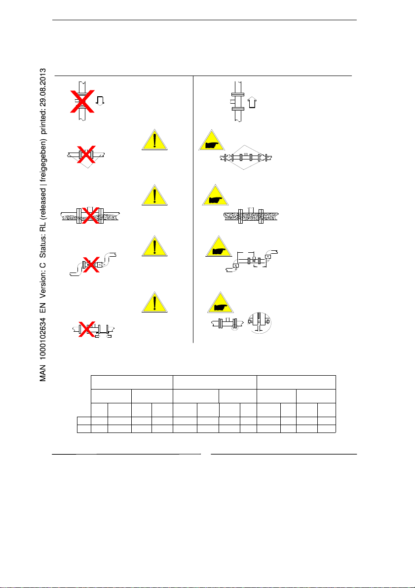
o Shrewdness and precautions
NO YES
For vertical installations with
descending flow direction
contact the manufacturer
LONG PIPE
void the installation of the
sensor in a lon
without an
same
pipe,
support of the
NTI VIBRATION JOINTS
LONG PIPE
void operatingwhen the
pipe is partially empty
void the installation next to
bows in pipes and respect
min. inlet and outlet sections
3 X DN
2 X DN
Avoid the approach of the
e and counter flange
flan
the closing force o
usin
the nuts
GASKET THICKNESS + 4mm
OPERATING TEMPERATURES
EBONITE LINING PP LINING PTFE LINING
Liquid Temp.
Min. Max Min. Max Min. Max Min. Max Min. Max Min. Max
° C 0 80 -5 60 0 60 0 60 -20 130 -10 60
° F 30 176 23 140 32 140 32 140 -4 266 14 140
Ambient
Temp.
Liquid Temp.
Ambient
Temp.
Liquid Temp.
For vertical installations is
preferable an ascendin
For installations on lon
pipes, please use the
anti vibration joints
Durin
operation, the pipe
must be either completely full
of liquid, or completely empty
Install the sensor at a min.
distance to bows in pipes and
hydraulic accessories
htening the nuts,
Before ti
place both the flan
and device as near to
as possible.
Ambient
Temp.
flow
es of pipe
ether
5
ESENS_FULLBORE_05.doc
Page 6
SENSOR FOR ELECTROMAGNETIC FLOW METER – MANUAL
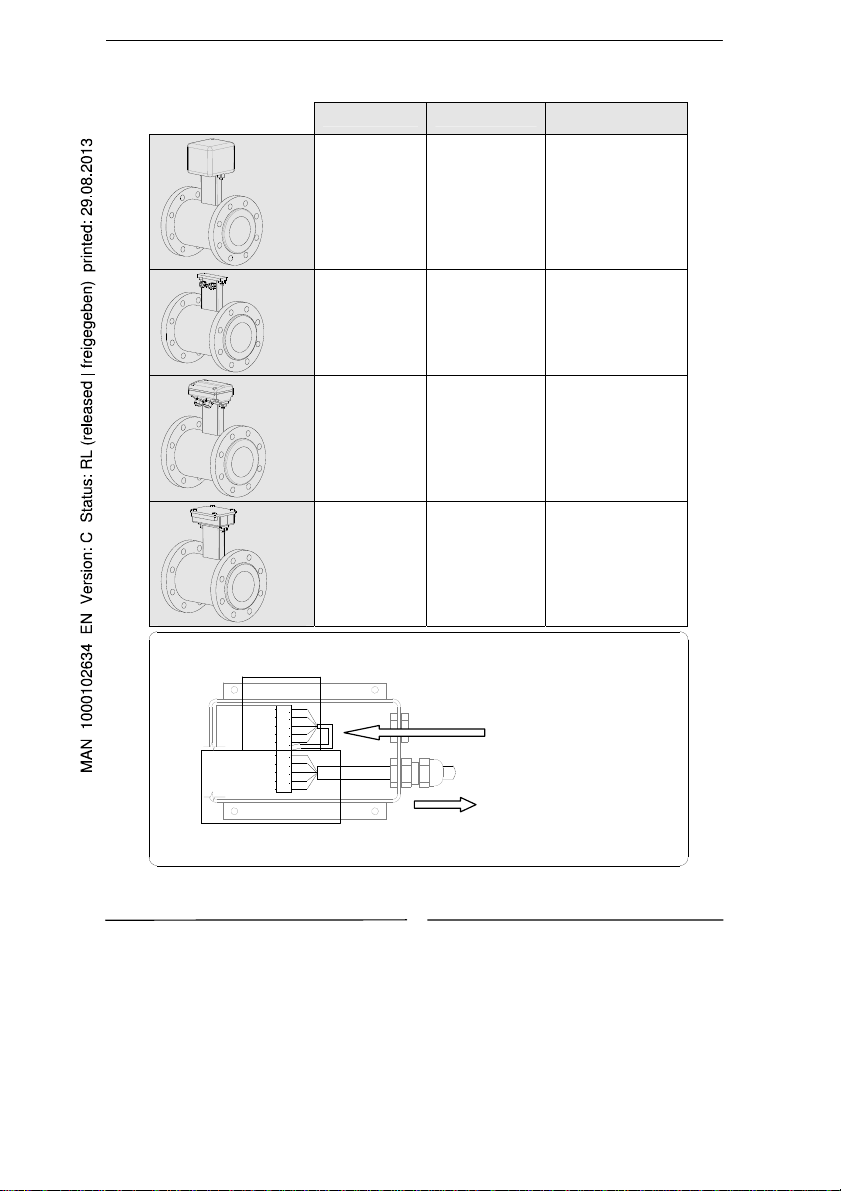
ELECTRICAL CONNECTIONS OF SENSOR TO TRANSMITTER
(CONNECTIONS TO TRANSMITTER: SEE RELATED MANUAL)
VERSION SUITABLE FOR
SENSOR’S
CONNECTION
COMPACT
ALL SENSORS
MODEL
NO CONNECTIONS
SEPARATE
WITHOUT
JUNCTIONS-
BOX
STAINLESS
STEEL MODEL
NO CONNECTIONS
REQUIRED
(CABLE ALREADY
CONNECTED AND
POTTED)
SEPARATE
WITH
JUNCTIONS-
BOX
ALL CARBON
STEEL MODELS
NO CONNECTIONS
REQUIRED
(CABLE ALREADY
CONNECTED AND
POTTED)
SEPARATE
WITH
PREAMPLIFIER
ALL SENSORS
MODEL
SEE BELOW
Cavo 1
Cavo 2
Cavo 3
Cavo 12
Cavo 13
Cavo 6
Cavo 7
Cavo 8
Cavo 9
Cavo 10
123456789
10
CABLE FROM INSIDE THE
SENSOR (PINS 1 – 5 ) ALREADY
CONNECTED
CABLE C014 TO THE
CONVERTER (PINS 6 – 10)
6
ESENS_FULLBORE_05.doc
Page 7

SENSOR FOR ELECTROMAGNETIC FLOW METER – MANUAL
GROUNDING INSTRUCTIONS
For correct operation of the meter, it is NECESSARY that the sensor and the
liquid are equipotential, so ALWAYS connect the sensor and converter to
ground:
o
Grounding with metallic pipe
Sensors with ground socket
on the connection box
Wafer sensors Flanged sensors
METALLIC
RING
o Grounding with insulating pipe
INSULATING GASKET
If the sensor is mounted on a pipe made of an insulating material,
If the sensor has to be mounted on a
do one of the following:
pipe made of an insulating material
- Install a metallic ring between the sensor flange and the
is necessary:
pipe counter flange,
- or use a sensor with the additional grounding electrode.
- Install two metallic ring between
the sensor flanges and the counter
flanges of the pipe lin e or:
- Use a sensor with the additional
grounding electrode
Grounding when there is a cathodic protection over the pipe
oo
METALLIC RING
INSULATING GASKET
ISOIL
If the sensor is mounted on a pipe with a cathode protection, do the
If the sensor must be install
following:
in the piping with a chatode
- use insulating bushes to isolate the bolts,
protection, is necessary:
- insert insulating gaskets on both sides of the rings to
ground the metallic rings and hence the liquid.
INSULATING
BUSH
- using insulating bushes to isolate
the bolts
- Grounding metallic rings should be
provided to ground the liquid using
insulating gasket between the rings
- IMPORTANT :
- IMPORTANT :
The ripple of DC power source used
The ripple of DC power
for cathodic protection
source used for
shall be = 0
cathodic protection
must be 0.
7
ESENS_FULLBORE_05.doc
Page 8
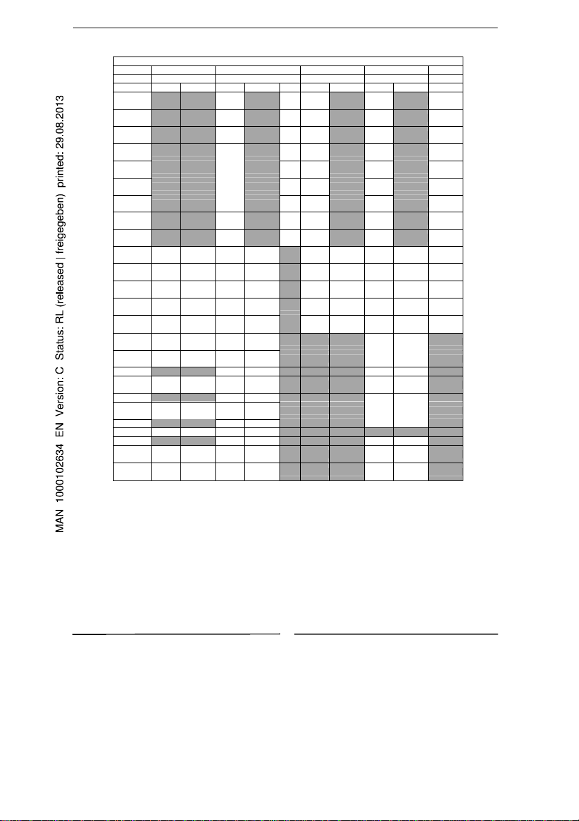
TORQUES (Nm) FOR SENSOR BOLTS (FLANGED & WAFER)
Kpa 1000 1600 2500 4000 6400
psi 140 260 350 600 1000
DN PTFE EBON. PTFE EBON. PP PTFE EBON. PTFE EBON. EBON.
25
32
40
50
65
80
100
125
150
200 148 432
250 123 359
300 142 415
350 172 502
400 217 632
450 194 564
500 224 652
550 (379) (1105) [608] [1772]
600 323 942
650 (429) (1251) [753] [2195]
700 356 1040
750 (451) (1315) [1105] [3223]
800 476 1388 549 1603
850 (563) (1642) [1373] [4006]
900 450 1312
1000 582 1699
OPERATIVE PRESSURE
25
(21)
43
(26)
53
(32)
68
(60)
90
(78)
53
(89)
59
(70)
77
(94)
108
(106)
99
288
(148)
(433)
140
408
(156)
(455)
175
510
(234)
(683)
205
598
(325)
(946)
282
821
(312)
(911)
281
981
(336)
(926)
382
1113
(317)
(924)
568
1658
(463)
(1350)
421
1230
(503)
(1468)
519
1515
(618)
(1803)
721
2105
(736)
(2146)
o Tighten uniformly in an alternating pattern
o The torque listed in tab are applicable to flanges:
EN1092-1, DIN 2501, BS 4504, ANSI B16.5 , JIS
o Use gaskets acc. to DIN 2690
o For DN > 1000 contact the manufacturer
o (***)= ANSI 150
o [***]= ANSI 300
NOTE FOR 3A APPROVED SENSORS
SENSOR FOR ELECTROMAGNETIC FLOW METER – MANUAL
19 25
28 43
36 53
52 68
75 45
41 53
56 83
71 112
106 135
134 391
204 595
201 588
324 945
426 1243
[398] [1161]
[465] [1356]
[774] [2258]
[947] [2761]
[1408] [4106]
[1598] [4662]
8
25
[32]
43
[40]
53
[63]
68
[35]
45
[53]
53
[68]
83
[94]
112
[130]
135
[113]
178
520
[178]
[519]
267
780
[185]
[540]
278
812
[275]
[803]
422
1231
[318]
[927]
619
1805
[411]
[1198]
ESENS_FULLBORE_05.doc
39
[32]
53
[40]
72
[63]
81
[35]
58
[53]
62
[68]
87
[94]
148
[130]
217
[113]
816
[519]
1124
[540]
1108
[803]
1684
[927]
2180
[1198]
Page 9
SENSOR FOR ELECTROMAGNETIC FLOW METER – MANUAL
V
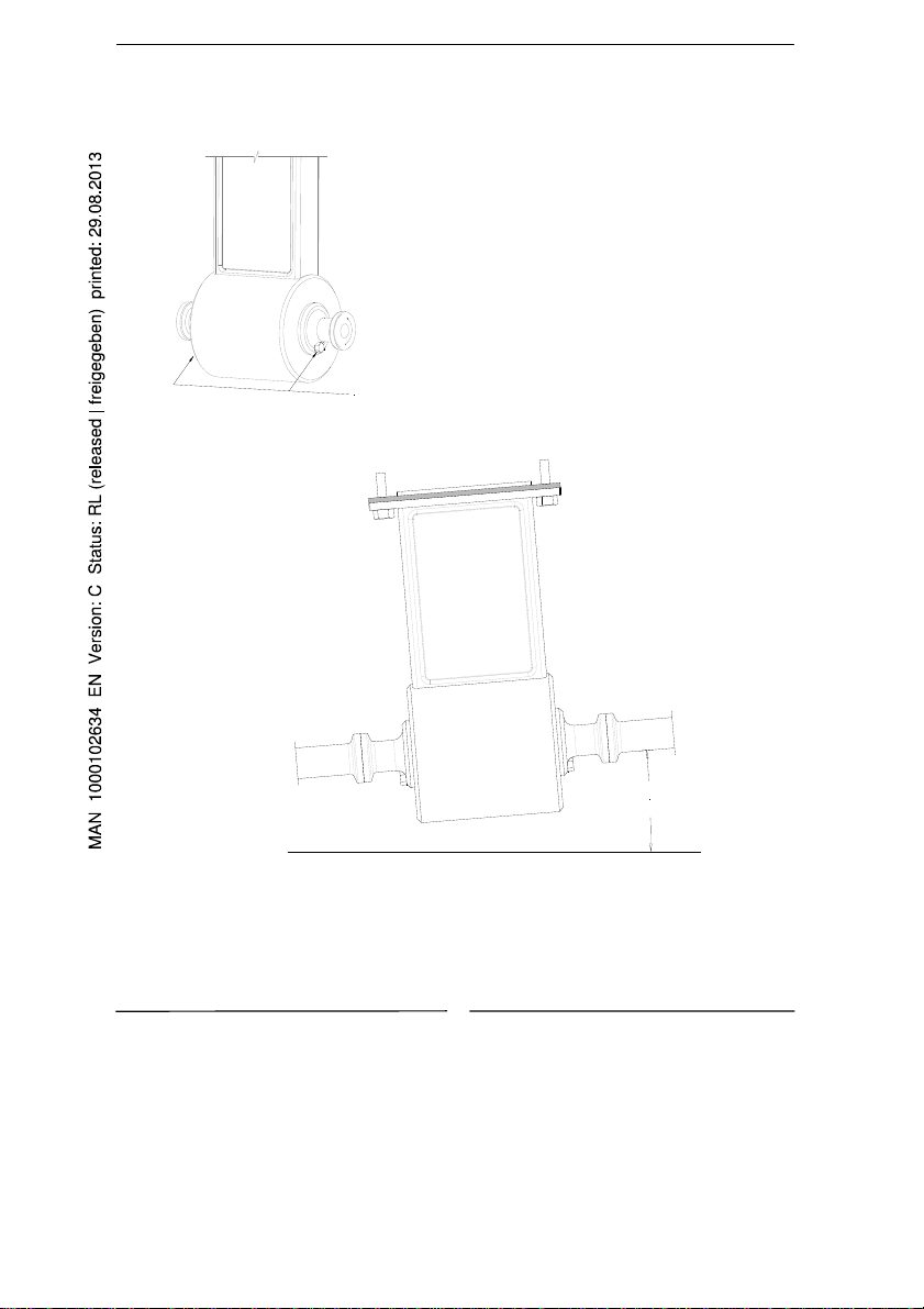
erify periodically the sensor’s seals integrity: with
piping full of liquid, unscrew the Inspection
screws (see drawing aside) and verify the total
absence of liquid from inspection hole!
After the above operation, REMEMBER to close
again the holes.
In case of leakage contact immediately our
Customer Service.
Inspection
screw
3°
When flowmeter is installed horizontally, ensure minimum angle of 3° for self draining purposes
9
ESENS_FULLBORE_05.doc
Page 10

SENSOR FOR ELECTROMAGNETIC FLOW METER – MANUAL
10
ESENS_FULLBORE_05.doc
Page 11

SENSOR FOR ELECTROMAGNETIC FLOW METER – MANUAL
11
ESENS_FULLBORE_05.doc
Page 12

SENSOR FOR ELECTROMAGNETIC FLOW METER – MANUAL
12
ESENS_FULLBORE_05.doc
Page 13

ELEKTROMAGNETISCHES DURCHFLUSSMESSGERÄT
„FULL BORE“-SENSOREN
INSTALLATIONSANLEITUNG
Page 14

SENSOR FÜR ELEKTROMAGNETISCHES DURCHFLUSSMESSGERÄT – HANDBUCH
INHALTSVERZEICHNIS
EINLEITUNG ......................................................................................... 3
INBETRIEBNAHME UND WARTUNG DER GERÄTE .................................... 3
SICHERHEIT ......................................................................................... 4
ALLGEMEINE INFORMATIONEN ZUR INSTALLATION DER SENSOREN ....... 4
BETRIEBSTEMPERATUREN ..................................................................... 5
ELEKTRISCHE VERBINDUNGEN ZWISCHEN SENSOR UND TRANSMITTER . 6
ERDUNGSANWEISUNGEN ...................................................................... 7
DREHMOMENTE (Nm) FÜR DIE SENSORBOLZEN (FLANSCH /
ZWISCHENFLANSCH) ............................................................................. 8
HINWEIS FÜR SENSOREN MIT 3A-ZULASSUNG ....................................... 9
2
DE_ESENS_FULLBORE_05.doc
Page 15

SENSOR FÜR ELEKTROMAGNETISCHES DURCHFLUSSMESSGERÄT – HANDBUCH
EINLEITUNG
- Dieses Handbuch ist integraler Bestandteil des Gerätes. Lesen Sie die hierin
enthaltenen Anweisungen sorgfältig durch, da sie wichtige Hinweise zur
sicheren Verwendung und zur Wartung enthalten.
- Änderungen der technischen Daten der in diesem Handbuch genannten
Produkte sind ohne Vorankündigung vorbehalten.
- Das Durchflussmessgerät muss für den Zweck verwendet werden, für den
es entwickelt wurde. Bei unsachgemäßer Verwendung, Manipulationen des
Gerätes oder seiner Komponenten oder Einsatz von Ersatzteilen anderer
Hersteller verfällt sofort jeglicher Garantieanspruch.
- Der Hersteller ist nur haftbar, wenn das Gerät in seiner
Originalkonfiguration und -einstellung verwendet wird.
- Das Durchflussmessgerät nimmt Messungen an Flüssigkeiten mit einer
Leitfähigkeit von über 5µS/cm vor; es besteht aus einem Sensor (in dieser
Anleitung beschrieben) und einem Transmitter, für letzteren siehe das
entsprechende Handbuch.
- Wenn der Sensor in der Kompaktversion mit Transmitter geliefert wird,
bitte beachten, dass die Betriebstemperaturgrenzwerte restrictiver sind.
Für details siehe die jeweiligen Handbücher.
- Bei Transport, Auspacken und Handhabung des Durchflussmessers
vorsichtig und sorgfältig vorgehen.
- Bei längerfristiger Lagerung und beim Transport den Originalbehälter an
einem trockenen Ort lagern, dabei nicht mehr als 3 Packungen
übereinander stapeln. Für Lagerung und Transport können Paletten
verwendet werden (im Fall von Holzkisten: nicht stapeln).
- Zur Reinigung des Gerätes nur ein feuchtes Tuch verwenden, und für die
Wartung/Reparaturen den Kundendienst kontaktieren.
- Bei der Entsorgung des Gerätes und der Verpackung die gesetzlichen
Bestimmungen strikt einhalten.
- Die Vervielfältigung dieses Handbuchs und jeglicher mit diesem Gerät
gelieferten Software ist verboten.
INBETRIEBNAHME UND WARTUNG DER GERÄTE
- Vor Inbetriebnahme des Gerätes immer eine geeignete sichere
Erdungsverbindung sicherstellen, wie auf Seite 6 angegeben.
- Überprüfen Sie in regelmäßigen Abständen: die Unversehrtheit der Kabel,
den festen Sitz der Dichtelemente (Kabelmuffen, Abdeckungen usw.), die
mechanische Befestigung des Gerätes an der Rohrleitung oder der
Wandhalterung.
3
DE_ESENS_FULLBORE_05.doc
Page 16

SENSOR FÜR ELEKTROMAGNETISCHES DURCHFLUSSMESSGERÄT – HANDBUCH
V
A
SICHERHEIT
LLGEMEINE INFORMATIONEN ZUR INSTALLATION DER SENSOREN
or Installation des Sensors die
Strömungsrichtung in der Rohrleitung
beachten.
Das Vorzeichen des Durchflusses ist
positiv, wenn die Strömungsrichtung
von – nach + verläuft, wie auf dem
Typenschild angegeben.
Wenn das Vorzeichen des
Durchflusses nach der Installation
gewechselt werden muss, reicht es,
das Vorzeichen des Koeffizienten KA
zu wechseln
Vor Einsatz des Gerätes immer eine sichere
Erdungsverbindung herstellen
o
Strömungsrichtung
Nicht versuchen, das Gerät zu reparieren. Wenn das Gerät
nicht korrekt arbeitet, wenden Sie sich bitte an den
nächstgelegenen Kundendienst
Während des Betriebs maximale Aufmerksamkeit aufwenden
ACHTUNG!!!
GEFAHR!!!
?
o Installation (Empfohlene Methode für ALLE SENSOREN MIT RINGBOLZEN)
Die Ringbolzen sind so bemessen, dass sie
nur das Gewicht des Messgerätes tragen
Hinweis: Für Sensor S054 empfehlen wir die Verwendung von Zentrierzylindern
Zentrierzylinder
4
DE_ESENS_FULLBORE_05.doc
+
Page 17

SENSOR FÜR ELEKTROMAGNETISCHES DURCHFLUSSMESSGERÄT – HANDBUCH
o Korrekter Einbau und Vorsichtsmaßnahmen
NEIN JA
Für senkrechte Installationen
mit Strömungsrichtung nach
unten wenden Sie sich bitte
an den Hersteller
LANGE
ROHRLEITUNG
Eine Installation des Sensors
in einer langen Rohrleitung
ohne Unterstützung
vermeiden
SCHWINGUNGSDÄMPFENDE DICHTUNGEN
LANGE ROHRLEITUNG
Betrieb mit teilweise leerer
Rohrleitung vermeiden
Installation in der Nähe von
Krümmungen und
Hydraulikzubehör vermeiden
3 X DN
2 X DN
BETRIEBSTEMPERATUREN
Die Flansche von Rohrleitung
und Sensor nicht durch das
Festziehen der Muttern
annähern
DICKE DER DICHTUNG + 4 mm
HARTGUMMI-AUSKLEIDUNG PP-AUSKLEIDUNG PTFE-AUSKLEIDUNG
Flüssigkeits-
Temp.
Min. Max. Min. Max. Min. Max. Min.
°C 0 80 -5 60 0 60 0 60 -20 130 -10 60
°F 30 176 23 140 32 140 32 140 -4 266 14 140
Umgebungs-
Temp.
Flüssigkeits-
Temp.
Umgebungs-
Temp.
Max
.
Flüssigkeits-
Temp.
Min.
Für senkrechte Installationen
ist die Strömungsrichtung
nach oben vorzuziehen
Für Installationen an langen
Rohrleitungen bitte
schwingungsdämpfende
Dichtungen verwenden
Im Betrieb muss die
Rohrleitung ganz mit
Flüssigkeit gefüllt oder völlig
leer sein
Den Sensor nicht in der Nähe
von Krümmungen und
Hydraulikzubehör installieren
Vor dem Festziehen der
Muttern den Flansch der
Rohrleitung so weit wie
möglich dem Flansch des
Sensors nähern
Umgebungs-
Temp.
Max
Min. Max.
.
5
DE_ESENS_FULLBORE_05.doc
Page 18

SENSOR FÜR ELEKTROMAGNETISCHES DURCHFLUSSMESSGERÄT – HANDBUCH
R
ELEKTRISCHE VERBINDUNGEN ZWISCHEN SENSOR UND TRANSMITTER
(ANSCHLUSS DES TRANSMITTERS: SIEHE EIGENES HANDBUCH)
VERSION GEEIGNET FÜR SENSOR-ANSCHLUSS
KOMPAKT
SEPARAT OHNE
ANSCHLUSSBOX
SEPARAT MIT
ANSCHLUSSBOX
SEPARAT MIT
VORVERSTÄRKER
ALLE
SENSOR-MODELLE
EDELSTAHL-MODELL
ALLE
KARBONSTAHL-
MODELLE
ALLE
SENSOR-MODELLE
KEINE ANSCHLÜSSE
KEINE ANSCHLÜSSE
ERFORDERLICH
(KABEL SCHON
ANGESCHLOSSEN UND
ABGEDICHTET)
KEINE ANSCHLÜSSE
ERFORDERLICH
(KABEL SCHON
ANGESCHLOSSEN UND
ABGEDICHTET)
SIEHE UNTEN
Cavo 1
Cavo 2
Cavo 3
Cavo 12
Cavo 13
Cavo 6
Cavo 7
Cavo 8
Cavo 9
Cavo 10
123456789
10
KABEL VOM SENSORINNEREN
(PINS 1–5 ) SCHON
ANGESCHLOSSEN
KABEL C014 ZUM TRANSMITTE
(PINS 6–10)
6
DE_ESENS_FULLBORE_05.doc
Page 19

SENSOR FÜR ELEKTROMAGNETISCHES DURCHFLUSSMESSGERÄT – HANDBUCH
A
ERDUNGSANWEISUNGEN
Für den korrekten Betrieb des Durchflussmessgerätes ist es NOTWENDIG, dass
der Sensor und die Flüssigkeit dasselbe Potential haben, schließen Sie daher
IMMER den Sensor und den Transmitter an Erdpotential an:
o
Erdung mit Metallrohr
Sensors with ground socket
Sensoren mit
on the connection box
Erdungsanschluss an der
nschlussbox
Wafer sensors Flanged sensors
ZwischenflanschVersion
Flansch-Version
ISOLIERDICHTUNG
METALLIC
METALL-
RING
RING
o Erdung mit Isolierrohr
INSULATING GASKET
Wenn der Sensor in einer Rohrleitung
If the sensor has to be mounted on a
pipe made of an insulating material
aus isolierendem Material installiert
is necessary:
werden muss, ist eine der folgenden
Maßnahmen notwendig:
- Zwei Metallringe zwischen den
- Install two metallic ring between
Sensorflanschen und den
the sensor flanges and the counter
flanges of the pipe lin e or:
Gegenflanschen der Rohrleitung
installieren oder:
- Use a sensor with the additional
grounding electrode
- Einen Sensor mit zusätzlicher
Erdungselektrode verwenden
oo
INSULATING GASKET
ISOLIERDICHTUNG
METALLIC RING
METALLRING
Erdung bei kathodischem Schutz über die Rohrleitung
- using insulating bushes to isolate
- Isolierhülsen zur Isolierung der
the bolts
Bolzen verwenden
- Grounding metallic rings should be
- Zur Erdung der Flüssigkeit sollten
provided to ground the liquid using
geerdete Metallringe installiert
insulating gasket between the rings
werden, dabei zwischen den
- IMPORTANT :
Ringen Isolierdichtungen
The ripple of DC power source used
- WICHTIG:
for cathodic protection
Die Welligkeit der für den
shall be = 0
kathodischen Schutz
ISOIL
If the sensor must be install
Wenn der Sensor in einer
in the piping with a chatode
Rohrleitung mit kathodischem
protection, is necessary:
Schutz installiert werden muss,
sind die folgenden Maßnahmen
notwendig:
INSULATING
ISOLIERHÜLSE
BUSH
verwendeten DC-Stromquelle
sollte 0 sein
7
DE_ESENS_FULLBORE_05.doc
Page 20

SENSOR FÜR ELEKTROMAGNETISCHES DURCHFLUSSMESSGERÄT – HANDBUCH
DREHMOMENTE (Nm) FÜR DIE SENSORBOLZEN (FLANSCH /
ZWISCHENFLANSCH)
25
(21)
43
(26)
53
(32)
68
(60)
90
(78)
53
(89)
59
(70)
77
(94)
108
(106)
99
(148)
140
(156)
175
(234)
205
(325)
282
(312)
281
(336)
382
(317)
568
(463)
421
(503)
519
(618)
721
(736)
(433)
(455)
(683)
(946)
(911)
(926)
1113
(924)
1658
(1350)
1230
(1468)
1515
(1803)
2105
(2146)
BETRIEBSDRUCK
19 25
28 43
36 53
52 68
75 45
41 53
56 83
71 112
106 135
288
134 391
408
204 595
510
201 588
598
324 945
821
426 1243
981
[398] [1161]
[465] [1356]
[774] [2258]
[947] [2761]
[1408] [4106]
[1598] [4662]
25
[32]
43
[40]
53
[63]
68
[35]
45
[53]
53
[68]
83
[94]
112
[130]
135
[113]
178
[178]
267
[185]
278
[275]
422
[318]
619
[411]
520
[519]
780
[540]
812
[803]
1231
[927]
1805
[1198]
39
[32]
53
[40]
72
[63]
81
[35]
58
[53]
62
[68]
87
[94]
148
[130]
217
[113]
816
[519]
1124
[540]
1108
[803]
1684
[927]
2180
[1198]
kPa 1000 1600 2500 4000 6400
psi 140 260 350 600 1000
DN PTFE HARTG. PTFE HARTG. PP PTFE HARTG. PTFE HARTG. HARTG.
25
32
40
50
65
80
100
125
150
200 148 432
250 123 359
300 142 415
350 172 502
400 217 632
450 194 564
500 224 652
550 (379) (1105) [608] [1772]
600 323 942
650 (429) (1251) [753] [2195]
700 356 1040
750 (451) (1315) [1105] [3223]
800 476 1388 549 1603
850 (563) (1642) [1373] [4006]
900 450 1312
1000 582 1699
o Gleichmäßig abwechselnd über Kreuz festziehen
o Anzuwendende Drehmomente für die folgenden Flanschtypen:
EN1092-1, DIN 2501, BS 4504, ANSI B16.5, JIS
o Die Verwendung von Dichtungen nach DIN 2690 wird empfohlen
o Für DN > 1000 wenden Sie sich bitte an den Hersteller
o (***) = ANSI 150
o [***] = ANSI 300
8
DE_ESENS_FULLBORE_05.doc
Page 21

A
g
HINWEIS FÜR SENSOREN MIT 3
Inspektions-
Inspection
schraube
screw
Bei horizontaler Installation des Durchflussmess
um eine Selbstentleerung zu ermöglichen.
SENSOR FÜR ELEKTROMAGNETISCHES DURCHFLUSSMESSGERÄT – HANDBUCH
-ZULASSUNG
Regelmäßig die Unversehrtheit der
Sensordichtungen überprüfen: Bei ganz mit
Flüssigkeit gefüllter Rohrleitung die
Inspektionsschrauben (siehe nebenstehende
Zeichnung) lösen, dabei muss die Kontrolle
ergeben, dass keinerlei Flüssigkeit aus dem
Inspektionsloch austritt!
Nach dem o.g. Vorgang DARAN DENKEN, die
Löcher wieder zu verschließen.
Im Fall von Flüssigkeitsaustritt wenden Sie sich
sofort an unseren Kundendienst.
3°
erätes einen Neigungswinkel von mindestens 3°,
9
DE_ESENS_FULLBORE_05.doc
Page 22

SENSOR FÜR ELEKTROMAGNETISCHES DURCHFLUSSMESSGERÄT – HANDBUCH
10
DE_ESENS_FULLBORE_05.doc
Page 23

SENSOR FÜR ELEKTROMAGNETISCHES DURCHFLUSSMESSGERÄT – HANDBUCH
11
DE_ESENS_FULLBORE_05.doc
Page 24

SENSOR FÜR ELEKTROMAGNETISCHES DURCHFLUSSMESSGERÄT – HANDBUCH
12
DE_ESENS_FULLBORE_05.doc
Page 25

MANUEL D’INSTALLATION
CAPTEURS À PASSAGE
DÉBITMÈTRE ÉLECTROMAGNÉTIQUE
INTÉGRAL
Page 26

CAPTEUR POUR DÉBITMÈTRE ÉLECTROMAGNÉTIQUE – MANUEL
TABLE DES MATIÈRES
INTRODUCTION .................................................................................... 3
DÉMARRAGE ET ENTRETIEN DES INSTRUMENTS .................................... 3
SÉCURITÉ : ........................................................................................... 4
INFORMATIONS GÉNÉRALES SUR L'INSTALLATION DU CAPTEUR ............ 4
TEMPÉRATURES DE FONCTIONNEMENT ................................................. 5
BRANCHEMENTS ÉLECTRIQUES ENTRE LE CAPTEUR ET
LE
TRANSMETTEUR ............................................................................... 6
INSTRUCTIONS DE MISE A LA TERRE ..................................................... 7
COUPLES DE SERRAGE (Nm) POUR LES BOULONS DU
CAPTEUR (BRIDES ET ENTRE-BRIDES) ................................................... 8
REMARQUE CONCERNANT LES CAPTEURS HOMOLOGUÉS 3A .................. 9
2
FR_ESENS_FULLBORE_05.doc
Page 27

CAPTEUR POUR DÉBITMÈTRE ÉLECTROMAGNÉTIQUE – MANUEL
INTRODUCTION
- Le présent manuel fait partie intégrante du produit. Lisez attentivement les
instructions qu’il contient car elles donnent des indications importantes
pour une utilisation et un entretien en toute sécurité.
- Les informations techniques et produits correspondants du manuel peuvent
être modifiés sans avertissement préalable.
- Le débitmètre doit être utilisé dans le but pour lequel il a été conçu. Toute
utilisation inadéquate, modification non autorisée de l’appareil ou de ses
pièces, ainsi que tout remplacement d’un ou plusieurs des composants
d’origine invalident automatiquement la garantie.
- La responsabilité du fabricant est engagée uniquement si l’appareil est
utilisé dans sa configuration et avec ses réglages d’origine.
- Le débitmètre effectue des mesures de liquides dont la conductivité est
supérieure à 5µS/cm ; il se compose d’un capteur (décrit dans ce manuel)
et d’un transmetteur (pour ce dernier, voir le manuel fourni).
- Si le capteur est ajouté au transmetteur en version compacte, il est
recommandé d’envisager une plage de températures d’exploitation plus
restreinte, ou de consulter les manuels correspondants.
- Transportez, déballez et manipulez le débitmètre avec précauti on.
- En cas de stockage prolongé et lors du transport, placez l’appareil dans son
emballage d’origine, à l’abri de l’humidité, et n’empilez pas plus de 3
paquets les uns au-dessus des autres. Le stockage et le transport sur
palettes est possible (si l’emballage est une caisse en bois, ne pas empiler
les caisses).
- L’appareil doit être nettoyé exclusivement avec un linge humide. Pour les
opérations de maintenance et les réparations, contactez le service clientèle.
- Pour la mise au rebut de l’appareil et de l’emballage, respectez la
réglementation en vigueur.
- La reproduction du présent manuel et de tout logiciel fourni avec
l'instrument est interdite.
DÉMARRAGE ET ENTRETIEN DES INSTRUMENTS
- Avant de démarrer l’instrument, établissez systématiquement une
connexion de mise à la terre sécurisée comme indiqué page 7.
- Vérifiez périodiquement : l’intégrité des câbles, le serrage des éléments
d'étanchéité (passe-câbles, couvercles, etc.) et la fixation mécanique de
l’instrument sur la conduite ou le support mural.
3
FR_ESENS_FULLBORE_05.doc
Page 28

CAPTEUR POUR DÉBITMÈTRE ÉLECTROMAGNÉTIQUE – MANUEL
V
SÉCURITÉ :
Avant d’utiliser l’instrument, établissez systématiquement une
connexion de mise à la terre sécurisée.
N’essayez jamais de réparer vous-même l’instrument. Si
l’instrument ne fonctionne pas correctement, contactez le
service d’assistance le plus proche.
Soyez extrêmement attentifs durant les opérations.
ATTENTION !!!
DANGER !!!
INFORMATIONS GÉNÉRALES SUR L'INSTALLATION DU CAPTEUR
o
Sens du débit
Avant d’installer le capteur,
déterminez le sens d’écoulement du
liquide dans la conduite.
Le signe du débit est positif lorsque
le sens du débit va de – vers +,
comme indiqué sur la plaque
signalétique.
Si l’appareil est monté à l’envers, le
signe du débit peut être corrigé en
modifiant le signe du coefficient KA.
?
o Installation (méthode recommandée pour TOUS LES CAPTEURS AVEC BOULON À
ŒIL)
Les boulons à œil sont dimensionnés pour
supporter uniquement le poids du débitmètre.
N.B. : Pour les capteurs S054, nous recommandons l’utilisation de vérins de
centrage.
érins de centrage
4
FR_ESENS_FULLBORE_05.doc
+
Page 29

CAPTEUR POUR DÉBITMÈTRE ÉLECTROMAGNÉTIQUE – MANUEL
j
o Conseils et précautions
NON OUI
Pour les installations
verticales avec sens de débit
descendant, contactez le
fabricant.
Pour les installations
verticales, il est préférable
d’avoir un débit ascendant.
CONDUITE LONGUE
Évitez d’installer le capteur
dans une longue conduite
sans support.
JOINTS ANTI-VIBRATIONS
CONDUITE LONGUE
Évitez un fonctionnement
avec une conduite en partie
vide.
Évitez une installation à
proximité de coudes ou de
composants hydrauliques.
3 X DN
2 X DN
TEMPÉRATURES DE FONCTIONNEMENT
°C 0 80 -5 60 0 60 0 60 -20 130 -10 60
°F 30 176 23 140 32 140 32 140 -4 266 14 140
Évitez de rapprocher la bride
et la contre-bride sous l’effet
de la force de serrage des
écrous.
LINING ÉBONITE LINING PP LINING PTFE
Temp. du
liquide
Min. Max. Min. Max. Min. Max. Min. Max. Min. Max. Min. Max.
Temp.
ambiante
ÉPAISSEUR DE JOINT + 4 mm
Temp. du
liquide
Temp.
ambiante
Temp. du
liquide
Pour les installations sur une
longue conduite, utilisez des
oints anti-vibrations.
Durant le fonctionnement, la
conduite doit être entièrement
remplie de liquide ou
complètement vide.
Installez le capteur à l'écart
des coudes et des
composants hydrauliques.
Avant de serrer les écrous,
rapprochez autant que
possible la bride de la
conduite de la bride du
capteur.
Temp.
ambiante
5
FR_ESENS_FULLBORE_05.doc
Page 30

CAPTEUR POUR DÉBITMÈTRE ÉLECTROMAGNÉTIQUE – MANUEL
(
)
R
BRANCHEMENTS ÉLECTRIQUES ENTRE LE CAPTEUR ET LE TRANSMETTEUR
(BRANCHEMENTS VERS LE TRANSMETTEUR : VOIR LE MANUEL CORRESPONDANT)
VERSION
COMPACTE
SÉPARÉE SANS
BOÎTE DE
JONCTION
SÉPARÉE AVEC
BOÎTE DE
JONCTION
SÉPARÉE AVEC
PRÉAMPLIFICATEUR
COMPATIBLE
AVEC
TOUS LES
MODÈLES DE
CAPTEURS
MODÈLE INOX
MODÈLES EN
ACIER CARBONE
MODÈLES DE
CAPTEURS
TOUS LES
TOUS LES
BRANCHEMENT DU
CAPTEUR
AUCUN
BRANCHEMENT
AUCUN
BRANCHEMENT
REQUIS
(CÂBLE DÉJÀ
CONNECTÉ ET
MOULÉ)
AUCUN
BRANCHEMENT
REQUIS
(CÂBLE DÉJÀ
CONNECTÉ ET
MOULÉ)
VOIR CI-DESSOUS
Cavo 1
Cavo 2
Cavo 3
Cavo 12
Cavo 13
Cavo 6
Cavo 7
Cavo 8
Cavo 9
Cavo 10
123456789
10
CÂBLE À PARTIR DE L'INTÉRIEU
DU CAPTEUR (BROCHES 1 – 5 )
DÉJÀ CONNECTÉ
CÂBLE C014 VERS LE
TRANSMETTEUR
BROCHES 6 –10
6
FR_ESENS_FULLBORE_05.doc
Page 31

CAPTEUR POUR DÉBITMÈTRE ÉLECTROMAGNÉTIQUE – MANUEL
T
É
INSTRUCTIONS DE MISE A LA TERRE
Pour un fonctionnement correct du débitmètre, il est IMPÉRATIF que
le capteur et le liquide aient le même potentiel : par conséquent, vous
devez TOUJOURS mettre à la terre le capteur et le transmetteur.
o
Mise à la terre avec conduite métallique
Sensors with ground socket
Capteurs avec prise de terre
on the connection box
sur le boîtier de connexion
Wafer sensors Flanged sensors
Capteurs avec entrebrides
Capteurs à brides
o Mise à la terre avec conduite isolée
METALLIC
ANNEAU
M
TALLIQUE
INSULATING GASKET
JOINT ISOLAN
RING
Si le capteur doit être monté sur une
If the sensor has to be mounted on a
pipe made of an insulating material
conduite en matériau isolant, il est
is necessary:
nécessaire :
- Install two metallic ring between
- d’installer deux anneaux
the sensor flanges and the counter
métalliques entre les brides du
flanges of the pipe lin e or:
capteur et les contre-brides de la
conduite, ou
- Use a sensor with the additional
grounding electrode
- d'utiliser un capteur avec une
électrode de mise à la terre
supplémentaire.
Mise à la terre avec une protection cathodique sur la conduite
oo
INSULATING GASKET
JOINT ISOLANT
ISOIL
METALLIC RING
ANNEAU MÉTALLIQUE
If the sensor must be install
Si le capteur doit être installé
in the piping with a chatode
sur une conduite avec
protection, is necessary:
protection cathodique, il est
nécessaire :
INSULATING
MANCHON
BUSH
ISOLANT
- using insulating bushes to isolate
- d’utiliser des manchons isolants
the bolts
pour isoler les boulons,
- Grounding metallic rings should be
- d’insérer un joint isolant de part et
provided to ground the liquid using
d’autre des anneaux métalliques
insulating gasket between the rings
pour mettre à la terre les anneaux
- IMPORTANT :
et donc le liquide.
The ripple of DC power source used
- IMPORTANT :
for cathodic protection
L’ondulation de la source
shall be = 0
d’alimentation DC utilisée pour
la protection cathodique doit
être = 0
7
FR_ESENS_FULLBORE_05.doc
Page 32

CAPTEUR POUR DÉBITMÈTRE ÉLECTROMAGNÉTIQUE – MANUEL
COUPLES DE SERRAGE (Nm) POUR LES BOULONS DU CAPTEUR
(BRIDES ET ENTRE-BRIDES)
Kpa 1000 1600 2500 4000 6400
psi 140 260 350 600 1000
DN PTFE ÉBON. PTFE ÉBON. PP PTFE ÉBON. PTFE ÉBON. ÉBON.
25
32
40
50
65
80
100
125
150
200 148 432
250 123 359
300 142 415
350 172 502
400 217 632
450 194 564
500 224 652
550 (379) (1105) [608] [1772]
600 323 942
650 (429) (1251) [753] [2195]
700 356 1040
750 (451) (1315) [1105] [3223]
800 476 1388 549 1603
850 (563) (1642) [1373] [4006]
900 450 1312
1000 582 1699
PRESSION DE SERVICE
25
19 25
(21)
43
28 43
(26)
53
36 53
(32)
68
52 68
(60)
90
75 45
(78)
53
41 53
(89)
59
56 83
(70)
77
71 112
(94)
108
106 135
(106)
99
288
(148)
(433)
140
408
(156)
(455)
175
510
(234)
(683)
205
598
(325)
(946)
282
821
(312)
(911)
281
981
(336)
(926)
382
1113
(317)
(924)
568
1658
(463)
(1350)
421
1230
(503)
(1468)
519
1515
(618)
(1803)
721
2105
(736)
(2146)
134 391
204 595
201 588
324 945
426 1243
[398] [1161]
[465] [1356]
[774] [2258]
[947] [2761]
[1408] [4106]
[1598] [4662]
25
[32]
43
[40]
53
[63]
68
[35]
45
[53]
53
[68]
83
[94]
112
[130]
135
[113]
178
[178]
267
[185]
278
[275]
422
[318]
619
[411]
o Serrer de manière homogène et en croix.
o Les couples de serrage indiqués entre parenthèses s’appliquent aux brides :
EN 1092-1, DIN 2501, BS 4504, ANSI B16.5, JIS
o Utiliser des joints selon DIN 2690.
o Pour DN > 1000, consulter le fabricant.
o (***)= ANSI 150
o [***]= ANSI 300
8
39
[32]
53
[40]
72
[63]
81
[35]
58
[53]
62
[68]
87
[94]
148
[130]
217
[113]
520
816
[519]
[519]
780
1124
[540]
[540]
812
1108
[803]
[803]
1231
1684
[927]
[927]
1805
2180
[1198]
[1198]
FR_ESENS_FULLBORE_05.doc
Page 33

Q
A
V
g
REMAR
UE CONCERNANT LES CAPTEURS HOMOLOGUÉS3
Vis
Inspection
d'inspection
screw
Si le débitmètre est installé à l’horizontale, prévoyez un an
vidange.
CAPTEUR POUR DÉBITMÈTRE ÉLECTROMAGNÉTIQUE – MANUEL
érifiez régulièrement l’intégrité des joints du
capteur : avec une conduite remplie de liquide,
dévissez les vis d’inspection (voir schéma cicontre) et assurez-vous de l’absence totale de
liquide dans le trou d’inspection.
Une fois cette opération terminée, N’OUBLIEZ PAS
de refermer les trous.
En cas de fuite, contactez immédiatement notre
service clientèle.
3°
le minimum de 3° pour l’auto-
9
FR_ESENS_FULLBORE_05.doc
Page 34

CAPTEUR POUR DÉBITMÈTRE ÉLECTROMAGNÉTIQUE – MANUEL
10
FR_ESENS_FULLBORE_05.doc
Page 35

CAPTEUR POUR DÉBITMÈTRE ÉLECTROMAGNÉTIQUE – MANUEL
11
FR_ESENS_FULLBORE_05.doc
Page 36

CAPTEUR POUR DÉBITMÈTRE ÉLECTROMAGNÉTIQUE – MANUEL
12
FR_ESENS_FULLBORE_05.doc
 Loading...