

Page 1

We reserve the right to make technical changes without notice.
Technische Änderungen vorbehalten.
Sous réserve de modifications techniques.
www.burkert.com
© 2010-2012 Bürkert SAS
Operating Instructions 1208/2_EU-ML_00563875_ORIGINAL_FR
Type S030
INLINE fitting
Operating Instructions
Bedienungsanleitung
Manuel d'utilisation
2
1. ABOUT THIS MANUAL ...........................................................3
2. INTENDED USE ..........................................................................5
3. BASIC SAFETY INFORMATION .........................................6
4. GENERAL INFORMATION .....................................................9
5. DESCRIPTION .......................................................................... 10
6. TECHNICAL DATA ..................................................................11
7. INSTALLATION ......................................................................... 31
8. MAINTENANCE ........................................................................ 41
9. SPARE PARTS AND ACCESSORIES ........................... 43
10. PACKAGING, TRANSPORT ............................................... 50
11. STORAGE ................................................................................... 51
12. DISPOSAL OF THE PRODUCT ....................................... 52
English
3
1. ABOUT THIS MANUAL
This manual describes the entire life cycle of the fitting. Please
keep this manual in a safe place, accessible to all users and
any new owners.
This manual contains important safety information.
Failure to comply with these instructions can lead to
hazardous situations.
• This manual must be read and understood.
Symbols used
danger
Warns against an imminent danger.
• Failure to observe this warning can result in death or in
serious injury.
Warning
Warns against a potentially dangerous situation.
• Failure to observe this warning can result in serious
injury or even death.
English
3
Page 2
4
attention
Warns against a possible risk.
• Failure to observe this warning can result in substantial
or minor injuries.
note
Warns against material damage.
• Failure to observe this warning may result in damage
to the fitting or system.
Indicates additional information, advice or
important recommendations.
Refers to information contained in this manual or in
other documents.
→ Indicates a procedure to be carried out.
English
5
2. INTENDED USE
Use of fittings S030 that does not comply with the
instructions could present risks to people, nearby
installations and the environment.
• The S030 fitting is intended to measure the flow rate
of clean fluids in the piping thanks to its paddle wheel.
The S030 fitting may be combined to an electronic module for displaying, monitoring or controlling
the flow rate, or a transmitter fitted with a bajonett
connection.
• Use this fitting in compliance with the specifications
and conditions of commissioning and use given in the
contractual documents, in this user manual and in the
user manual for the device which is inserted into it.
• Safe and trouble-free operation of the fitting depends
on its proper transport, storage and installation, as well
as careful operation and maintenance.
• Only use this fitting as intended.
Restraints
Observe any existing restraints when the fitting is exported.
English
5
6
3. BASIC SAFETY INFORMATION
This safety information does not take into account:
• any contingencies or occurences that may arise during
installation, use and maintenance of the devices.
• the local safety regulations for which the operating company
is responsible including the staff in charge of installation
and maintenance.
Danger due to high pressure in the installation.
Danger due to high temperatures of the fluid.
Danger due to the nature of the fluid.
Various dangerous situations
• Prevent any unintentional power supply switch-on.
• Ensure that installation and maintenance work are
carried out by qualified, authorised personnel in
possession of the appropriate tools.
• Guarantee a set or controlled restarting of the process, after a power supply interruption.
English
7
Various dangerous situations
• Observe the general technical rules when installing
and using the fitting.
• Use the fitting only if in perfect working order and
in compliance with the instructions provided in the
instruction manual.
• Do not use the fittings in PVC or PP in explosive
atmospheres.
• Do not use this fitting to measure gas flow rates.
• Do not use fluid that is incompatible with the materials
from which the fitting is made.
• Do not use this fitting in an environment incompatible
with the materials from which it is made.
• Do not subject the fitting to mechanical loads (by placing
objects on top of it or by using it as a step, for example).
• Do not make any external modifications to the device. Do
not paint any part of the fitting.
English
7
Page 3

8
note
The fitting may be damaged by the fluid in contact
with.
• Systematically check the chemical compatibility of the
component materials of the fitting and the fluids likely
to come into contact with it (for example: alcohols,
strong or concentrated acids, aldehydes, alkaline
compounds, esters, aliphatic compounds, ketones,
halogenated aromatics or hydrocarbons, oxidants and
chlorinated agents).
English
9
4. GENERAL INFORMATION
To contact the manufacturer of the device use following
address:
Bürkert SAS
Rue du Giessen
BP 21
F-67220 TRIEMBACH-AU-VAL
The addresses of our international branches can be found
on the Internet at: www.burkert.com
Warranty conditions
The condition governing the legal warranty is the conforming
use of the S030 in observance of the operating conditions
specified in this manual.
Information on the Internet
You can find the user manuals and technical data sheets
regarding the type S030 at: www.burkert.com
English
9
10
5. DESCRIPTION
Area of application
The S030 fitting is intended to measure the flow rate of clean
fluids in DN6 to DN65 pipes thanks to its paddle-wheel. It
must be combined with an electronic device (indicator, flow
threshold detector or transmitter) which converts the pulse
frequency due to paddle-wheel rotation.
The electronic device can be removed without opening the
piping or stopping the process.
Measuring principle
The fluid flowing in the piping makes the paddle-wheel turn.
The paddle-wheel rotational frequency f is proportional to
the flow rate.
English
11
6. TECHNICAL DATA
Conditions of use
The fluid temperatures and pressures may be
restricted by the electronic device mounted on the
fitting: refer to the relevant manual.
Ambient temperature depends on the device mounted
on the S030. Refer to the relevant
manual.
Pressure class PN16 (or PN40 on request) for metal
fittings.
PN 10 for plastic fittings, depends on
fluid temperature, see Fig. 1.
Fluid temperature depends on the material from which
the S030 fitting and the paddle-wheel
are made, see the following table.
Paddle-wheel
material
Body fitting material Fluid temperature
PP • Stainless steel
• Brass
• PVDF
• PP
+0 °C...+80 °C
• PVC +0 °C...+50 °C
English
11
Page 4

12
Paddle-wheel
material
Body fitting material Fluid temperature
PVDF • Stainless steel
• Brass
• PVDF
-15 °C...+100 °C
• PP +0 °C...+80 °C
• PVC +0 °C...+50 °C
A (Type SE30 Ex)
10
9
8
7
6
5
4
3
2
1
0
-30 -10 +10 +30 +50 +70 +90 +110
16
15
14
13
12
11
P [bar]
T [°C]
Metal
PVDF
PVDF
PVC+PP
PVC
PP
Fluid temperature
Fluid pressure
Fig. 1: Fluid pressure / temperature dependency curves
for fittings used on their own
English
13
Conformity to the pressure
directive
The S030 fitting complies with article 3 of §3 from 97/23/
CE directive.
Acc. to the 97/23/CE pressure directive, the device can
only be used in the following cases (depending on max.
pressure, pipe diameter and fluid):
Type of fluid Conditions
Fluid group 1 § 1.3.a only DN ≤ 25
Fluid group 2 § 1.3.a DN ≤ 32
or DN > 32 and PNxDN ≤ 1000
Fluid group 1 § 1.3.b PNxDN ≤ 2000
Fluid group 2 § 1.3.b DN ≤ 200
Certificates available
• Certificate 3.1
• Certificate 2.2
• Roughness certificate
• Calibration certificate
• FDA approval (with EPDM seal), S030 in stainless steel
only
English
13
14
General technical data
Max. Fluid viscosity 300 cSt
Type of fluid Clean, neutral or slightly aggressive
Rate of solid particles in
the fluid
max. 1 %
Max. particle size 0,5 mm
Measurement range of the
flow rate in the pipe
0,3 to 10 m/s
Accuracy, with standard K
factor
≤ ±(0.5 % of the full scale +
2.5 % of the measured value)*
Linearity ≤ ± 0,5 % of the full scale
(10 m/s)*
Repeatability ± 0,4 % of the measured value*
* determined in the following reference conditions: medium =
water, water and ambient temperatures 20 °C, min. upstream and
downstream distances respected, appropriate pipe dimensions.
Diameters available
The diameters available depend on the design of the S030
fitting.
Refer to the graph on page 32 to determine the
appropriate DN of the pipe and fitting.
English
15
Design of the S030 fitting connections DN available
Internal threads
DN15 to DN50
External threads acc. to G, NPT or Rc, in
stainless steel or brass
DN06 to DN50
External threads acc. to SMS 1145, in
stainless steel
DN25 to DN50
Weld ends, in stainless steel
DN08 to DN65
Clamp
DN08 to DN65
Flanges
DN15 to DN50
True-union
DN08 to DN50
Spigot, in PVC, PP or PVDF
DN15 to DN50
Materials
Sensor holder
Paddle-wheel
Axis
Seal
Body
Fig. 2: Sectional drawing of the S030 fitting
Component Material
Seal FKM
EPDM with FDA agreement on request
English
15
Page 5

16
Component Material
Body Stainless steel (316L - 1.4404)
Brass (CuZn39Pb2)
PVC, PP, PVDF
Screws Stainless steel (316L - 1.4404)
Paddle-wheel PVDF
PP on request
Shaft and bearings Ceramics (Al
2O3
)
Table 1: Dimensions of the fittings with internal threads
acc. to G, Rc or NPT in stainless steel or brass
DN [mm] P [mm] A [mm] D [inch] L [mm]
15 34,5 84,0 G 1/2
NPT 1/2
Rc 1/2
16,0
17,0
15,0
20 32,0 94,0 G 3/4
NPT 3/4
Rc 3/4
17,0
18,3
16,3
25 32,2 104,0 G 1
NPT 1
Rc 1
23,5
18,0
18,0
32 35,8 119,0 G 1 1/4
NPT 1 1/4
Rc 1 1/4
23,5
21,0
21,0
40 39,6 129,0 G 1 1/2
NPT 1 1/2
Rc 1 1/2
23,5
20,0
19,0
English
17
DN [mm] P [mm] A [mm] D [inch] L [mm]
50 45,7 148,5 G 2
NPT 2
Rc 2
27,5
24,0
24,0
A
L
D
P
Table 2: Dimensions of the fittings with external threads
acc. to G, NPT or Rc in stainless steel, brass,
PVC or PVDF
DN
[mm]P [mm]
A [mm] D [inch] [mm] L [mm]
06 29,5 90,0 G 1/4 or 1/2 - 14,0
08 29,5 90,0 1/2* M 16 x 1,5 14,0
15 34,5 84,0 G 3/4 - 11,5
20 32,0 94,0 G 1 - 13,5
25 32,2 104,0 G 1 1/4 - 14,0
32 35,8 119,0 G 1 1/2 - 18,0
40 39,6 129,0 - M 55 x 2 19,0
50 45,7 148,5 - M 64 x 2 20,0
English
17
18
DN
[mm]P [mm]
A [mm] D [inch] [mm] L [mm]
A
L
D
P
Table 3: Dimensions of the fittings with external threads
acc. to SMS 1145, in stainless steel
DN [mm] P [mm] A [mm] D
25 32,0 130 M 40 x 1/6
40 35,8 164 M 60 x 1/6
50 39,6 173 M 70 x 1/6
A
P
D
English
19
Table 4: Dimensions of the fitting with weld ends acc.
to EN ISO 1127/ISO 4200, SMS 3008,
BS 4825/ASME BPE and DIN 11850 Rg2, in
stainless steel
DN
[mm]P [mm]
A [mm] Standard D [mm] s
[mm]
08 -
-
29,5
-
-
90,0
EN ISO 1127 / ISO 4200
SMS 3008
ASME BPE
DIN 11850 Rg2
-
-
13,00
-
-
1,50
15 34,5
-
34,5
84,0
-
84,0
EN ISO 1127 / ISO 4200
SMS 3008
ASME BPE
DIN 11850 Rg2
21,30
-
19,0
1,60
-
1,50
20 32,0
34,5
34,5
94,0
84,0
84,0
EN ISO 1127 / ISO 4200
SMS 3008
ASME BPE
DIN 11850 Rg2
26,9
19,05
23,00
1,60
1,65
1,50
25 32,2
32,0
32,0
32,0
104,0
94,0
94,0
94,00
EN ISO 1127 / ISO 4200
SMS 3008
BS 4825/ASME BPE
DIN 11850 Rg2
33,70
25,00
25,40
29,00
2,00
1,20
1,65
1,50
32 35,8
32,2
32,2
119,0
104,0
104,0
EN ISO 1127 / ISO 4200
SMS 3008
BS 4825/ASME BPE
DIN 11850 Rg2
42,40
32,00
35,00
2,00
1,65
1,50
40 39,6
35,8
35,8
35,8
129,0
119,0
119,0
119,0
EN ISO 1127 / ISO 4200
SMS 3008
BS 4825/ASME BPE
DIN 11850 Rg2
48,30
38,00
38,10
41,00
2,00
1,20
1,65
1,50
English
19
Page 6

20
DN
[mm]P [mm]
A [mm] Standard D [mm] s
[mm]
50 45,7
39,6
39,6
39,6
148,5
128,0
128,0
128,0
EN ISO 1127 / ISO 4200
SMS 3008
BS 4825/ASME BPE
DIN 11850 Rg2
60,30
51,00
50,80
53,00
2,60
1,20
1,65
1,50
65 -
45,7
45,7
-
147,0
147,0
-
EN ISO 1127 / ISO 4200
SMS 3008
BS 4825/ASME BPE
DIN 11850 Rg2
63,50
63,50
-
1,60
1,65
-
A
P
s
D
English
21
Table 5: Dimensions of the Clamp fittings in stainless
steel acc. to:
a) ISO for pipes acc. to EN ISO 1127/
ISO 4200,
b) SMS 3017/ISO 2852*,
c) BS 4825/ASME BPE* or,
d) DIN 32676
* Available with an internal roughness of Ra = 0.8 µm
DN [mm] P [mm] A [mm] Stan-
dard
D2
[mm]
D1
[mm]
D [mm]
08 -
29,5
-
125
a
b
c
d
-
-
10,0
-
-
27,5
-
-
34,0
15 34,5
-
29,5
130
-
119
a
b
c
d
18,10
-
16,00
27,5
-
27,5
34,0
-
34,0
20 32,0
34,5
34,5
150
119
119
a
b
c
d
23,70
15,75
20,00
43,5
19,6
27,5
50,5
25,0
34,0
25 32,2
32,0
32,0
32,0
160
129
129
136
a
b
c
d
29,70
22,60
22,10
26,00
43,5
43,5
43,5
43,5
50,5
50,5
50,5
50,5
32 35,8
-
-
-
180
-
-
-
a
b
c
d
38,40
-
-
-
43,5
-
-
-
50,5
-
-
-
English
21
22
40 39,6
35,8
35,8
35,8
200
161
161
161
a
b
c
d
44,30
35,60
34,80
38,00
56,5
43,5
43,5
43,5
64,0
50,5
50,5
50,5
50 45,7
39,6
39,6
39,6
230
192
192
170
a
b
c
d
55,10
48,60
47,50
50,00
70,5
56,5
56,5
56,5
77,5
64,0
64,0
64,0
65 -
45,7
45,7
-
216
216
-
a
b
c
d
60,30
60,20
-
70,5
70,5
-
77,5
77,5
-
D
P
2D
1D
A
Table 6: Dimensions, in mm, of the fitting with flanges
acc. to EN1092-1 (ISO PN16), ANSI B16-51988 or JIS 10 K in stainless steel
DN P A Stan-
dard
L Z D2 D1 D
15 34,5 130
130
152
EN
ANSI
JIS
23,5 4x14.0
4x15.8
4x15.0
45,0
34,9
51,0
65,0
60,3
70,0
95,0
89,0
95,0
20 32,0 150
150
178
EN
ANSI
JIS
28,5 4x14.0
4x15.8
4x15.0
58,0
42,9
56,0
75,0
69,8
75,0
105,0
99,0
100,0
English
23
25 32,2 160
160
216
EN
ANSI
JIS
28,5 4x14.0
4x15.8
4x19.0
68.,0
50,8
67,0
85,0
79,4
90,0
115,0
108,0
125,0
32 35,8 180
180
229
EN
ANSI
JIS
31,0 4x18.0
4x15.8
4x19.0
78,0
63,5
76,0
100,0
88,9
100,0
140,0
117,0
135,0
40 39,6 200
200
241
EN
ANSI
JIS
36,0 4x18.0
4x15.8
4x19.0
88,0
73,0
81,0
110,0
98,4
105,0
150,0
127,0
140,0
50 45.7 230
230
267
EN
ANSI
JIS
41.0 4x18.0
4x19.0
4x19.0
102,0
92,1
96,0
125,0
120,6
120,0
165,0
152,0
155,0
A
L
D2
D1
D
Z
P
Table 7: Dimensions of the true-union fittings acc. to
DIN 8063, ASTM D 1785/76 or acc. to JIS K in
PVC, DIN 16962 in PP or acc. to ISO 10931
in PVDF
* only available in PVC
DN
[mm]P [mm]
A [mm] Standard A1
[mm]
A2
[mm]D [mm]
D1
[mm]
08* 29,5 122,0
-
-
DIN/ISO
ASTM
JIS
92
-
-
90
-
-
12,00
-
-
-
-
-
English
23
Page 7
24
DN
[mm]P [mm]
A [mm] Standard A1
[mm]
A2
[mm]D [mm]
D1
[mm]
15 34,5 128,0
130,0
129,0
DIN/ISO
ASTM
JIS
96 90 20,00
21,30
18,40
43
20 32,0 144,0
145,6
145,0
DIN/ISO
ASTM
JIS
106 100 25,00
26,70
26,45
53
25 32,2 160,0
161,4
161,0
DIN/ISO
ASTM
JIS
116 110 32,00
33,40
32,55
60
32 35,8 168,0
170,0
169,0
DIN/ISO
ASTM
JIS
116 110 40,00
42,20
38,60
74
40 39,6 188,0
190,2
190,0
DIN/ISO
ASTM
JIS
127 120 50,00
48,30
48,70
83
50 45,7 212,0
213,6
213,0
DIN/ISO
ASTM
JIS
136 130 63,00
60,30
60,80
103
A
A1
A2
P
D
1D
English
25
Table 8: Dimensions of the spigot fittings acc. to
DIN 8063 in PVC, acc. to DIN 16962 in PP or
acc. to ISO 10931 in PVDF
DN
[mm]P [mm]A [mm]
Standard L [mm] D
[mm]H [mm]
15 34,5 90
85
85
DIN 8063
DIN 16962
ISO 10931
16,5
14,0
14,0
20 17,5
20 32,0 100
92
92
DIN 8063
DIN 16962
ISO 10931
20,0
16,0
16,0
25 17,5
25 32,2 110
95
95
DIN 8063
DIN 16962
ISO 10931
23,0
18,0
18,0
32 21,5
32 35,8 110
100
100
DIN 8063
DIN 16962
ISO 10931
27,5
20,0
20,0
40 27,5
40 39,6 120
106
106
DIN 8063
DIN 16962
ISO 10931
30,0
23,0
23,0
50 31,5
50 45,7 130
110
110
DIN 8063
DIN 16962
ISO 10931
37,0
27,0
27,0
63 39,5
English
25
26
DN
[mm]P [mm]A [mm]
Standard L [mm] D
[mm]H [mm]
PH
D
L
A
K factors (pulse/litre)
The K factors have all been determined under the following
reference conditions: fluid = water, water and room temperatures of 20°C, minimum upstream and downstream
distances respected, appropriate pipe dimensions.
If the S030 fitting is combined with an electronic
device which does not automatically convert the
K factors, make the conversion using one of the
following formulae:
K factor in pulse/US gallon = K factor in pulse/litre
x 3.785 to obtain a flow rate value in US gallon/
time unit
K factor in pulse/UK gallon = K factor in pulse/litre
x 4,546 to obtain a flow rate value in UK gallon/
time unit
English
27
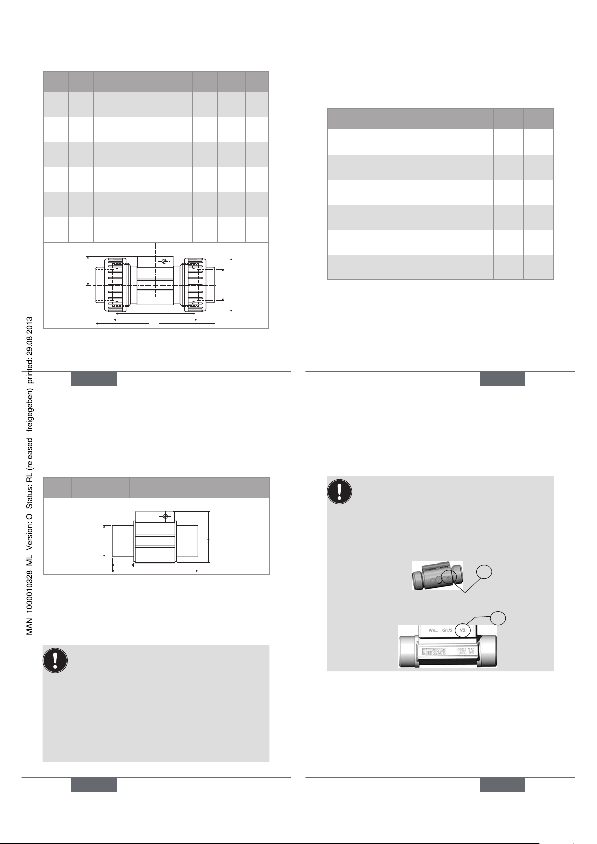
Two versions of the S030 in DN15 and DN20
exist, having different K factors.
Only version 2, identified by the "v2" marking, is
available from March 2012. The "v2" marking can
be found:
• on the bottom of the DN15 or DN20 fitting in
plastic:
V2
• on the side of the DN15 or DN20 fitting in metal:
V2
English
27
Page 8
28
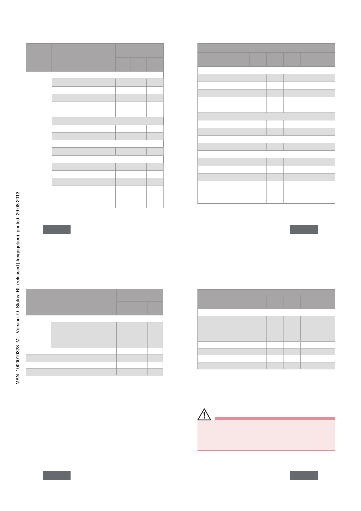
Material Type of connections and
standard
K factors (pulse/
litre)
DN6 DN8 DN15
Stainless steel
Weld ends acc. to:
SMS 3008
-
- -
BS 4825 / ASME BPE
-
- -
DIN 11850 Rg2
-
278 106
EN ISO 1127 / ISO
4200
-
- 106
External threads acc. to:
SMS 1145
-
- -
G
440
278 106
Internal threads acc. to:
G, Rc, NPT
-
- 106
Clamp acc. to:
SMS 3017 / ISO 2852 - - BS 4825 / ASME BPE - - DIN 32676 - 278 106
ISO (pipe EN ISO 1127/
ISO 4200)
- - 106
English
29
K factors (pulse/litre)
DN15
v2
1)
DN20 DN20
v2
1)
DN25 DN32 DN40 DN50 DN65
- - - 66,9 - 31,1 19,9 11,4
- 106 74,5 66,9 49,0 31,1 19,9 11,4
74,5 106 74,5 66,9 49,0 31,1 19,9 74,5 66,5 - 49,0 31,8 19,8 11,4 -
- - - 66,9 - 31,1 19,9 74,5 66,5 - 49,0 31,8 19,8 11,4 -
74,5 66,5 - 49,0 31,8 19,8 11,4 -
- - - 66,9 - 31,1 19,9 11,4
- 106 74,5 66,9 - 31,1 19,9 11,4
74,5 106 74,5 66,9 - 31,1 19,9 74,5 66,5 - 49,0 31,8 19,8 11,4 -
1)
See page 27.
English
29
30
Material
Type of connections and
standard
K factors (pulse/
litre)
DN6 DN8 DN15
Stainless
steel
Flanges acc. to:
EN 1092-1 (ISO PN16)
ANSI B16-5-1998
JIS 10K
440
- 106
Brass
All 440
278 106
PVC
All 440
278 116
PP
All -
- 110
PVDF
All 440
278 118
English
31
K factors (pulse/litre)
DN15
v2
1)
DN20
DN20
v2
1)
DN25 DN32 DN40 DN50 DN65
74,5 66,5 - 49,0 31,8 19,8 11,4 -
74,5 66,5 - 49,0 31,8 19,8 11,4 84,7 75,3 - 52,9 28,5 17,3 10,2 89,9 74,2 - 52,9 28,4 17,4 10,1 90,3 78,0 - 57,0 31,7 19,0 10,9 -
1)
See page 27
7. INSTALLATION
Safety instructions
danger
Risk of injury due to high pressure in the installation.
• Stop the circulation of fluid, cut-off the pressure
and drain the pipe before loosening the process
connections.
English
31
Page 9
32
danger
Risk of injury due to high fluid temperatures.
• Use safety gloves to handle the fitting.
• Stop the circulation of fluid and drain the pipe before
loosening the process connections.
Risk of injury due to the nature of the fluid.
• Respect the prevailing regulations on accident prevention and safety relating to the use of hazardous
products.
Warning
Risk of injury due to non-conforming installation.
• Fluidic installation can only be carried out by qualified
and authorised personnel with the appropriate tools.
• Observe the installation instructions for the measuring
device inserted into the fitting.
Risk of injury due to an uncontrolled restart.
• Ensure that the restart of the installation is controlled
after any interventions on it.
English
33
Warning
Risk of injury if the fluid pressure/ temperature
dependency is not respected.
• Take into account the fluid pressure/ temperature
dependency according to the materials from which the
fitting is made and to the measuring device used (see
the relevant user manual).
• Comply with the Pressure Directive 97/23/EC.
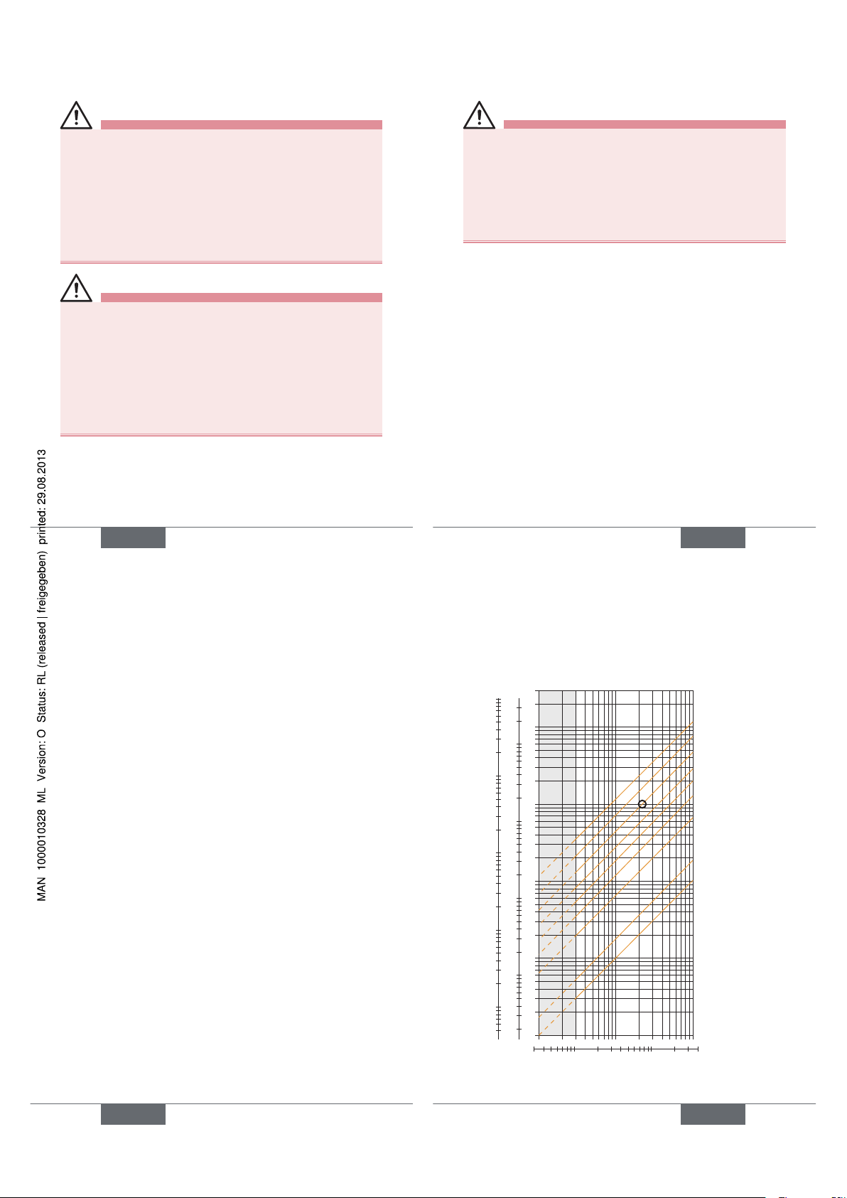
→ Select an appropriate fitting regarding to the flow
velocity and the flow rate of the fluid in the piping, see
the following charts:
The graph is used to determine the DN of the pipe and the
fitting appropriate to the application, according to the fluid
velocity and the flow rate.
English
33
34
Selection example:
- Specification: if the nominal flow is 10 m
3
/h the dimensioning of the optimal flow rate must be contained in 2 to
3m/s
- Answer: on the chart, the intersection of flow rate and
flow velocity gives the appropriate diameter, DN40 or
DN50 for fittings with *.
* For fittings:
- with external threads according to SMS 1145,
- with weld-ends according to SMS 3008, BS 4825 /
ASME BPE or DIN 11850 Rg2
- Clamp according to SMS 3017 / ISO 2852 or BS 4825 /
ASME BPE or DIN 32676
English
35
0.1 0.3 0.5 1 3
5
10
0.01
0.02
0.05
0.1
0.2
0.5
1
2
5
10
20
50
100
200
m
3
/h
0.2
0.5
1
2
5
10
20
50
100
200
500
1000
2000
3000
l/min
0.3 0.5 1 3 5 10
30
m/s
fps
gpm
0.05
0.1
0.2
0.5
1
2
5
10
20
50
100
200
500
1000
DN65
DN50 (DN65)*
DN40 (DN50)*
DN32 (DN40)*
DN25 (DN32)*
DN20 (DN25)*
DN15 (DN15 or
DN20)*
DN08
DN06
flow rate
Fluid velocity
English
35
Page 10
36
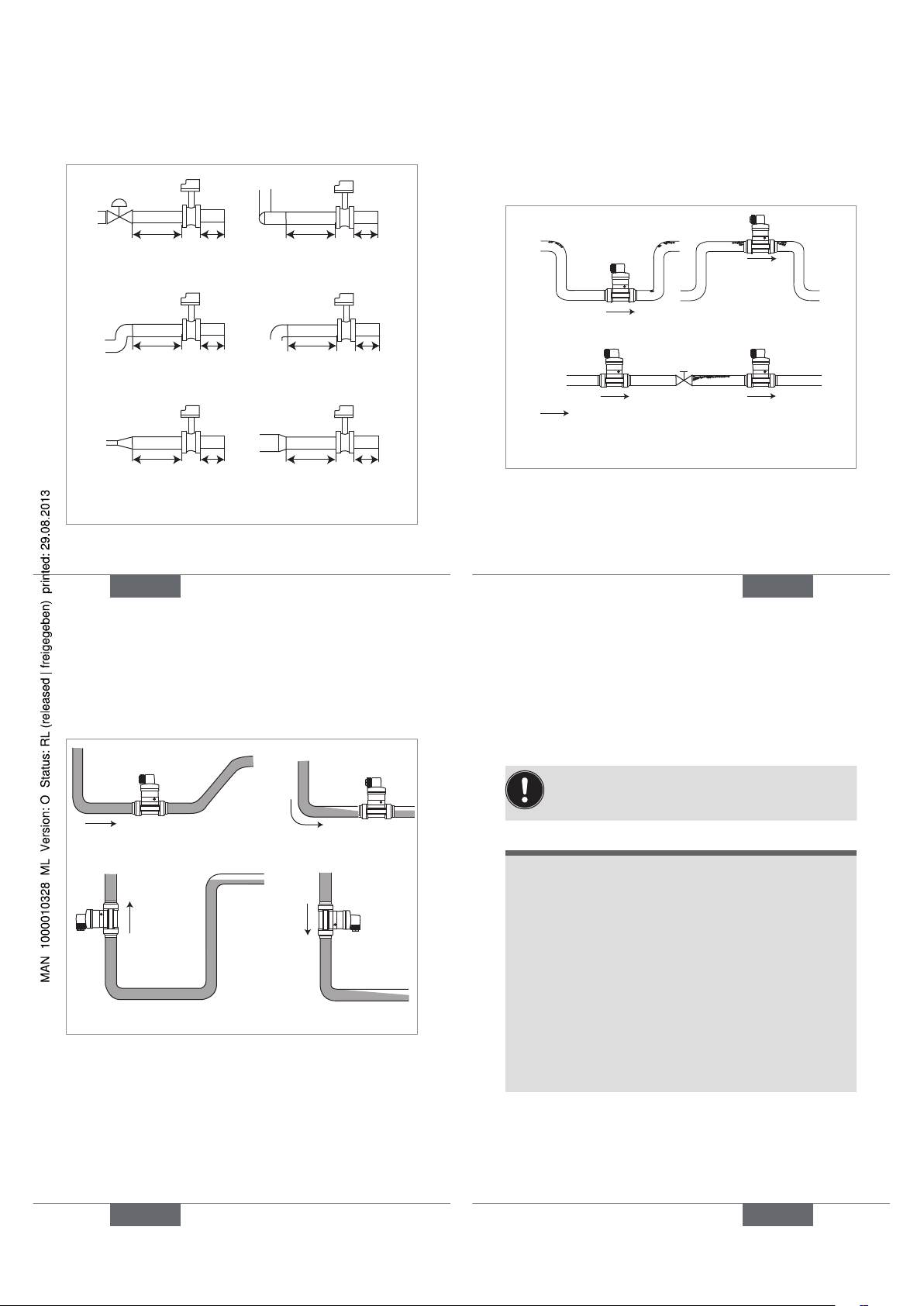
→ Install the fitting on the pipe to comply with the
upstream and downstream distances defined by
standard EN ISO 5167-1 (see Fig. 3).
50 x DN 5 x DN
40 x DN 5 x DN
25 x DN 5 x DN 20 x DN 5 x DN
18 x DN 5 x DN 15 x DN 5 x DN
With control valve
Pipe with 2 elbows
at 90°
Pipe with 2 elbows at 90°
in 3 dimensions
Pipe with 1 elbow at 90°
or 1 T-piece
With pipe expansion
With pipe
reduction
Fig. 3: Upstream and downstream distances depending
on the design of the pipes.
English
37
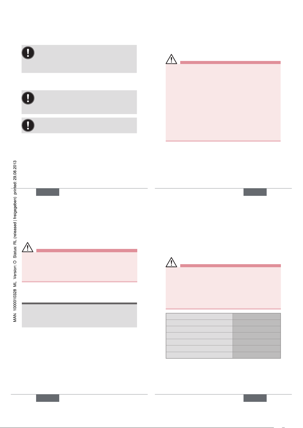
→ Use a flow conditioner, if necessary, to obtain the best
accuracy.
→ Prevent the formation of air bubbles in the pipe (see
Fig. 4).
→ Ensure the pipe is always filled with liquid (see Fig. 5).
Correct
Correct
Incorrect
Incorrect
Direction of fluid flow
Fig. 4: Additional recommendations on installation
English
37
38
Correct
Incorrect
Correct Incorrect
Fig. 5: Additional recommendations on installation
English
39
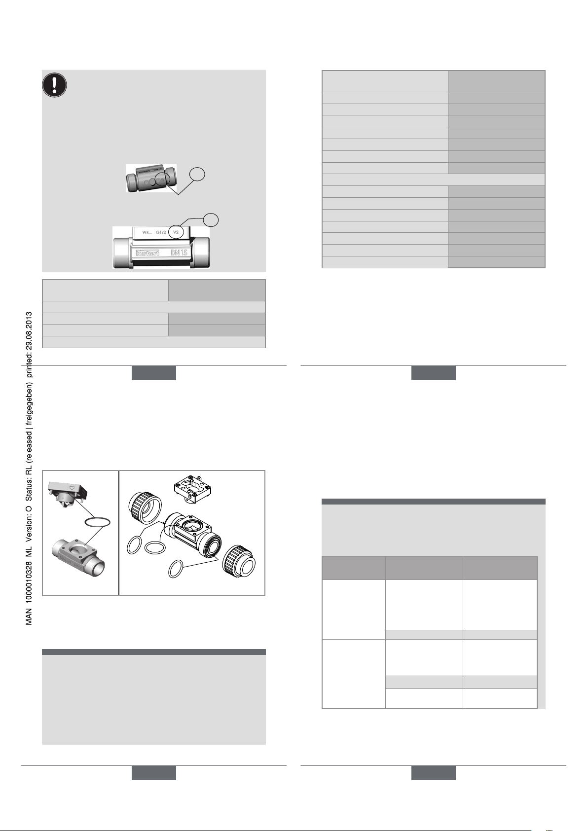
Installing a fitting with weld ends
Follow the previously described general installation
recommendations.
note
The seal on the fitting with weld-end connections
may be damaged during welding.
→ Before welding the weld-ends, unscrew the 4 tigh-
tening screws.
→ Remove the sensor holder.
→ Remove the seal.
→ Weld the weld-ends.
→ After welding, correctly replace the seal in the
groove.
→ Replace the sensor holder.
→ Tighten the 4 screws in an alternating pattern, app-
lying a nominal tightening torque of 1,5 Nm.
English
39
Page 11
40
Installing a Clamp fitting
→ Make sure the seals are in good condition.
→ Place seals adapted to the process (temperature,
fluid type) in the grooves of the Clamp fitting.
→ Fix the Clamp fitting to the pipe by means of a clamp collar.
Installing a flange fitting
→ Make sure the seals are in good condition.
→ Place seals adapted to the process (temperature,
fluid type) in the grooves of each connection.
Make sure the seal remains in the groove while
tightening the flange.
→ Tighten the flange to fix the fitting to the pipe.
English
41
8. MAINTENANCE
Safety instructions
danger
Risk of injury due to high pressure in the installation.
• Stop the circulation of fluid, cut-off the pressure
and drain the pipe before loosening the process
connections.
Risk of injury due to high fluid temperatures.
• Use safety gloves to handle the fitting.
• Stop the circulation of fluid and drain the pipe before
loosening the process connections.
• Keep all easily flammable fluid or material away from the
fitting.
Risk of injury due to the nature of the fluid.
• Respect the prevailing regulations on accident prevention and safety relating to the use of aggressive fluids.
English
41
42
Warning
Risk of injury due to non-conforming maintenance.
• Maintenance must only be carried out by qualified and
skilled staff with the appropriate tools.
• Ensure that the restart of the installation is controlled
after any interventions.
Cleaning
note
The fitting may be damaged by the cleaning product.
• Clean the fitting with a cloth dampened with water or
a detergent compatible with the materials the fitting is
made of.
English
43
9. SPARE PARTS AND
ACCESSORIES
attention
Risk of injury and/or damage caused by the use of
unsuitable parts.
Incorrect accessories and unsuitable spare parts may
cause injuries and damage the fitting and the surrounding area.
• Use only original accessories and original spare parts
from Bürkert.
Accessories Order code
Certificate
Certificate 3.1
440 790
Certificate 2.2
440 789
Roughness certificate
444 898
Calibration certificate
550 676
FDA approval
449 788
English
43
Page 12
44
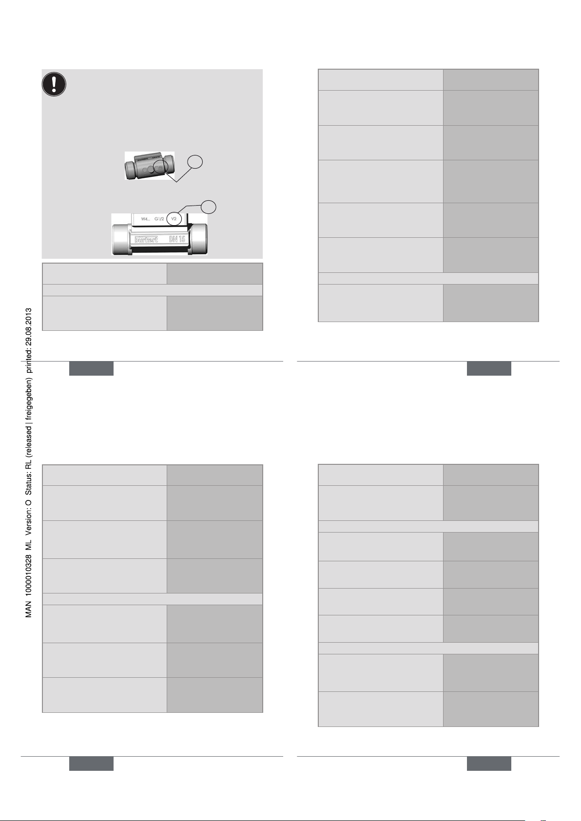
Two versions of the S030 in DN15 and DN20
exist, having different K factors.
Only version 2, identified by the "v2" marking, is
available from March 2012. The "v2" marking can
be found:
• on the bottom of the DN15 or DN20 fitting in
plastic:
V2
• on the side of the DN15 or DN20 fitting in metal:
V2
Spare parts Order code
Sensor holder in stainless steel
With PVDF paddle-wheel, FKM
seal, screws and certificate, for
DN06, DN08, DN15 v2 and
DN20 v2
448 678
English
45
Spare parts Order code
With PVDF paddle-wheel, FKM
seal, screws and certificate, for
DN15 (except DN15 v2 and
DN20 v2) to DN65
432 306
With PVDF paddle-wheel, EPDM
seal, screws and certificate, for
DN15 (except DN15 v2 and
DN20 v2) to DN65
432 305
With PVDF paddle-wheel, EPDM
seal, screws and certificate, internal roughness =0,8 µm for DN15
(except DN15 v2 and DN20 v2) to
DN65
434 149
With PVDF paddle-wheel, EPDM
seal, screws and certificate, for
DN06, DN08, DN15 v2 and
DN20 v2
554 896
With PP paddle-wheel, EPDM seal,
screws and certificate, for DN15
(except DN15 v2 and DN20 v2) to
DN65.
449 425
Sensor holder in brass
With PVDF paddle-wheel, FKM
seal, screws and certificate, for
DN06, DN08, DN15 v2 and
DN20 v2
448 677
English
45
46
Spare parts Order code
With PVDF paddle-wheel, FKM
seal, screws and certificate, for
DN15 (except DN15 v2 and
DN20 v2) to DN65
432 304
With PVDF paddle-wheel, EPDM
seal, screws and certificate, for
DN15 (except DN15 v2 and
DN20 v2) to DN65
432 303
With PP paddle-wheel, EPDM seal,
screws and certificate, for DN15
(except DN15 v2 and DN20 v2) to
DN65.
449 866
Sensor holder in PVC
With PVDF paddle-wheel, FKM
seal, screws and certificate, for
DN06, DN08, DN15 v2 and
DN20 v2
448 674
With PVDF paddle-wheel, FKM
seal, screws and certificate, for
DN15 (except DN15 v2 and
DN20 v2) to DN65
432 298
With PVDF paddle-wheel, EPDM
seal, screws and certificate, for
DN15 (except DN15 v2 and
DN20 v2) to DN65
432 297
English
47
Spare parts Order code
With PP paddle-wheel, EPDM seal,
screws and certificate, for DN15
(except DN15 v2 and DN20 v2) to
DN65.
443 982
Sensor holder in PP
With PVDF paddle-wheel, FKM
seal, screws and certificate, for
DN15 to DN65.
432 300
With PVDF paddle-wheel, EPDM
seal, screws and certificate, for
DN15 to DN65.
432 299
With PP paddle-wheel, FKM seal,
screws and certificate, for DN15
to DN65.
552 881
With PP paddle-wheel, EPDM seal,
screws and certificate, for DN15
to DN65.
443 983
Sensor holder in PVDF
With PVDF paddle-wheel, FKM
seal, screws and certificate, for
DN06, DN08, DN15 v2 and
DN20 v2
448 676
With PVDF paddle-wheel, FKM
seal, screws and certificate, for
DN15 (except DN15 v2 and
DN20 v2) to DN65
432 302
English
47
Page 13

48
Spare parts Order code
With PVDF paddle-wheel, EPDM
seal, screws and certificate, for
DN15 (except DN15 v2 and
DN20 v2) to DN65
432 301
Two versions of the S030 in DN15 and DN20
exist, having different K factors.
Only version 2, identified by the "v2" marking, is
available from March 2012. The "v2" marking can
be found:
• on the bottom of the DN15 or DN20 fitting in
plastic:
V2
• on the side of the DN15 or DN20 fitting in metal:
V2
English
49
Spare parts Order code
Set of O-rings (DN6 to DN65) for metal fittings
FKM
426 340
EPDM
426 341
Set of O-rings in FKM for plastic fittings
DN08
448 679
DN15
431 555
DN20
431 556
DN25
431 557
DN32
431 558
DN40
431 559
DN50
431 560
Set of O-rings in EPDM for plastic fittings
DN08
448 680
DN15
431 561
DN20
431 562
DN25
431 563
DN32
431 564
DN40
431 565
DN50
431 566
English
49
50
Metal fitting
Plastic fitting
Fig. 6: Position of O-rings in an S030 fitting
10. PACKAGING, TRANSPORT
attention
Damage due to transport
• Transport may damage an insufficiently protected part.
• Transport the fitting in shock-resistant packaging and
away from humidity and dirt.
• Do not expose the fitting to temperatures that may
exceed the admissible storage temperature range.
English
51
11. STORAGE
attention
Poor storage can damage the fitting.
• Store the fitting in a dry place away from dust.
• Storage temperature of the S030 fitting:
Paddle-wheel
material
Body fitting material Storage
temperature
PP • Stainless steel
• Brass
• PVDF
• PP
-15 °C...+80 °C
• PVC -15 °C...+60 °C
PVDF • Stainless steel
• Brass
• PVDF
-15 °C...+100 °C
• PP -15 °C...+80 °C
• PVC -15 °C...+60 °C
English
51
Page 14

52
12. DISPOSAL OF THE PRODUCT
attention
Damage to the environment caused by products
contaminated by fluids.
• Dispose of the fitting and its packaging in an environmentally-friendly way.
• Keep to the existing provisions on the subject of waste
disposal and environmental protection.
English
53
English
53
54
English
Page 15

We reserve the right to make technical changes without notice.
Technische Änderungen vorbehalten.
Sous réserve de modifications techniques.
www.burkert.com
© 2010-2012 Bürkert SAS
Operating Instructions 1208/2_EU-ML_00563875_ORIGINAL_FR
Type S030
INLINE-Fitting
Bedienungsanleitung
Deutsch
2
1. DIE BEDIENUNGSANLEITUNG ......................................... 3
2. BESTIMMUNGSGEMÄSSE VERWENDUNG................5
3. GRUNDLEGENDE SICHERHEITSHINWEISE ..............6
4. ALLGEMEINE HINWEISE .......................................................9
5. BESCHREIBUNG .................................................................... 10
6. TECHNISCHE DATEN .......................................................... 11
7. INSTALLATION ......................................................................... 31
8. WARTUNG .................................................................................. 41
9. ERSATZTEILE UND ZUBEHÖR ....................................... 43
10. VERPACKUNG, TRANSPORT ........................................... 50
11. LAGERUNG ................................................................................51
12. ENTSORGUNG ........................................................................ 52
deutsch
3
1. DIE BEDIENUNGSANLEITUNG
Die Bedienungsanleitung beschreibt den gesamten Lebenszyklus des Fittings. Bewahren Sie diese Anleitung so auf,
dass sie für jeden Benutzer zugänglich ist und jedem neuen
Eigentümer des Fittings wieder zur Verfügung steht.
Diese Bedienungsanleitung enthält wichtige Informationen zur Sicherheit!
Das Nichtbeachten dieser Hinweise kann zu gefährlichen
Situationen führen.
• Diese Bedienungsanleitung muss gelesen und verstanden werden.
Darstellungsmittel
Gefahr!
Warnt vor einer unmittelbaren Gefahr!
• Bei Nichteinhaltung sind Tod oder schwere Verletzungen die Folge.
deutsch
Page 16

4
WarnunG!
Warnt vor einer möglicherweise gefährlichen
Situation!
• Bei Nichteinhaltung drohen schwere Verletzungen
oder Tod.
VOrSIChT!
Warnt vor einer möglichen Gefährdung!
• Nichtbeachtung kann mittelschwere oder leichte Verletzungen zu Folge haben.
hInWeIS!
Warnt vor Sachschäden!
• Bei Nichtbeachtung kann das Fitting oder die Anlage
beschädigt werden.
bezeichnet wichtige Zusatzinformationen, Tipps
und Empfehlungen.
verweist auf Informationen in dieser Bedienungsanleitung oder in anderen Dokumentationen.
→ markiert einen Arbeitsschritt, den Sie ausführen
müssen.
deutsch
5
2. BESTIMMUNGSGEMÄSSE
VERWENDUNG
Bei nicht bestimmungsgemäßem Einsatz dieses
Fittings können Gefahren für Personen, Anlagen in
der Umgebung und die Umwelt entstehen.
• Mit dem Fitting S030 kann aufgrund des integrierten
Flügelrads der Durchfluss gemessen werden. Das
Fitting S030 kann mit Elektronikmodulen zur Anzeige,
Überwachung und Kontrolle oder mit Transmittern
verbunden werden, die mit einem Bajonett-Anschlusssystem ausgestattet sind.
• Für den Einsatz sind die in den Vertragsdokumenten
und dieser Bedienungsanleitung und in der
Bedienungsanleitung des eingesteckten Geräts
spezifizierten zulässigen Daten, Betriebs- und
Einsatzbedingungen zu beachten.
• Zum sicheren und problemlosen Einsatz des Fittings
müssen Transport, Lagerung und Installation ordnungsgemäß erfolgen, außerdem müssen Betrieb und
Wartung sorgfältig durchgeführt werden.
• Achten Sie immer darauf, dieses Fitting auf ordnungsgemäße Weise zu verwenden.
Beschränkungen
Beachten Sie bei der Ausfuhr des Fittings gegebenenfalls
bestehende Beschränkungen.
deutsch
6
3. GRUNDLEGENDE
SICHERHEITSHINWEISE
Diese Sicherheitshinweise berücksichtigen keine
• Zufälligkeiten und Ereignisse, die bei Montage, Betrieb und
Wartung der Geräte auftreten können.
• Ortsbezogenen Sicherheitsbestimmungen, für deren
Einhaltung, auch in Bezug auf das Installations- und Wartungspersonal, der Betreiber verantwortlich ist.
Gefahr durch hohen Druck in der Anlage!
Gefahr durch hohe Flüssigkeitstemperaturen!
Gefahr aufgrund der Art der Flüssigkeit!
Allgemeine Gefahrensituationen.
• Die Anlage nicht unbeabsichtigt betätigen.
• Installations- und Instandhaltungsarbeiten dürfen
nur von autorisiertem Fachpersonal mit geeignetem
Werkzeug ausgeführt werden.
• Nach einer Unterbrechung der elektrischen Versorgung ist ein definierter oder kontrollierter Wiederanlauf
des Prozesses zu gewährleisten.
deutsch
7
Allgemeine Gefahrensituationen.
• Bei der Einsatzplanung und dem Betrieb des Fittings
die allgemeinen Regeln der Technik einhalten.
• Betreiben Sie das Fitting nur in einwandfreiem Zustand
und unter Beachtung der Bedienungsanleitung.
• Die Fittings aus PVC oder PP nicht in einer explosionsfähigen Atmosphäre verwenden.
• Dieses Fitting nicht zur Messung eines Gasdurchflusses
verwenden.
• Keine Flüssigkeit verwenden, die sich nicht mit den
Werkstoffen verträgt, aus denen das Fitting besteht.
• Dieses Fitting nicht in einer Umgebung verwenden, die
mit den Materialien, aus denen es besteht, inkompatibel
ist.
• Belasten Sie das Fitting nicht mechanisch (z. B. durch
Ablage von Gegenständen oder als Trittstufe).
• Nehmen Sie keine äußerlichen Veränderungen an den
Gehäusen vor. Keinen Teil des Fittings lackieren.
deutsch
Page 17

8
hInWeIS!
Das Fitting kann durch das Medium beschädigt
werden.
• Kontrollieren Sie systematisch die chemische
Verträglichkeit der Werkstoffe, aus denen das Fitting
besteht, und der Flüssigkeiten, die mit diesem in
Berührung kommen können (zum Beispiel: Alkohole,
starke oder konzentrierte Säuren, Aldehyde, Basen,
Ester, aliphatische Verbindungen, Ketone, aromatische
oder halogenierte Kohlenwasserstoffe, Oxidations- und
chlorhaltige Mittel).
deutsch
9
4. ALLGEMEINE HINWEISE
Sie können mit dem Hersteller des Fittings unter folgender
Adresse Kontakt aufnehmen:
Bürkert SAS
Rue du Giessen
BP 21
F-67220 TRIEMBACH-AU-VAL
Die Kontaktdaten der Niederlassungen befinden sich im
Internet unter: www.burkert.com
Gewährleistung
Voraussetzung für die Gewährleistung ist der
bestimmungsgemäße Gebrauch des S030 unter
Beachtung der im vorliegenden Handbuch spezifizierten
Einsatzbedingungen.
Informationen im Internet
Bedienungsanleitungen und Datenblätter zum Typ S030
finden Sie im Internet unter: www.buerkert.de
deutsch
10
5. BESCHREIBUNG
Vorgesehener Einsatzbereich
Mit dem Fitting S030 kann aufgrund des integrierten Flügelrads der Durchfluss in Rohrleitungen mit DN6 bis DN65
gemessen werden. Es muss in Verbindung mit einem Elektronikmodul zur Erfassung/Konvertierung der durch die Rotation
des Flügelrads erzeugten Impulsfrequenz verwendet werden
(Anzeige, Kontrollgerät oder Transmitter).
Das Elektronikmodul kann ohne Öffnung der Rohrleitung
oder Unterbrechung des Prozesses ersetzt werden.
Messprinzip
Die in der Rohrleitung strömende Flüssigkeit führt zur Drehung
des Flügelrads. Die Rotationsfrequenz f dieses Flügelrads ist
zum Durchfluss proportional.
deutsch
11
6. TECHNISCHE DATEN
Betriebsbedingungen
Die Temperatur und der Druck der Flüssigkeit
können durch das verwendete Elektronikmodul
eingeschränkt sein, siehe die entsprechende
Bedienungsanleitung.
Umgebungstemperatur
(im Betrieb)
je nach verwendetem Elektronikmodul;
siehe jeweilige Bedienungsanleitung
Druckklasse PN16 (oder PN40 auf Anforderung)
für die Fittings aus Metall.
PN10 für die Fittings aus Kunststoff, je
nach Temperatur der Flüssigkeit, siehe
Bild 1.
Flüssigkeitstemperatur je nach Werkstoffe des Flügelrads
und des Gehäuses des Fittings; siehe
nächste Tabelle.
FlügelradWerkstoff
Werkstoff des
Fittinggehäuses
Flüssigkeitstemperatur
PP • Edelstahl
• Messing
• PVDF
• PP
+0 °C...+80 °C
• PVC +0 °C...+50 °C
deutsch
Page 18

12
FlügelradWerkstoff
Werkstoff des
Fittinggehäuses
Flüssigkeitstemperatur
PVDF • Edelstahl
• Messing
• PVDF
-15 °C...+100 °C
• PP +0 °C...+80 °C
• PVC +0 °C...+50 °C
A (Type SE30 Ex)
10
9
8
7
6
5
4
3
2
1
0
-30 -10 +10 +30 +50 +70 +90 +110
16
15
14
13
12
11
P [bar]
T [°C]
Metall
PVDF
PVDF
PVC+PP
PVC
PP
Flüssigkeitstemperatur
Flüssigkeits-Druck
Bild 1: Druck-Temperatur-Abhängigkeitskurven der
Flüssigkeit, für die Fittings S030 selbst
deutsch
13
Einhaltung der
Druckgeräterichtlinie
Das Fitting S030 entspricht den Anforderungen von Artikel
3§3 der Druckgeräterichtlinie 97/23/EG.
Gemäß der Druckgeräterichtlinie 97/23/EG darf das
Produkt (in Abhängigkeit vom Höchstdruck, dem DN der
Leitung und der Art der Flüssigkeit) nur in den folgenden
Fällen verwendet werden:
Art der Flüssigkeit Voraussetzungen
Flüssigkeitsgruppe 1
Kap. 1.3.a
nur DN ≤ 25
Flüssigkeitsgruppe 2
Kap. 1.3.a
DN ≤ 32
oder DN > 32 und PNxDN ≤ 1000
Flüssigkeitsgruppe 1
Kap. 1.3.b
PNxDN ≤ 2000
Flüssigkeitsgruppe 2
Kap. 1.3.b
DN ≤ 200
Verfügbare Zertifikate
• Zertifikat 3.1
• Zertifikat 2.2
• Zertifikat bezüglich Rauigkeit
• Kalibrierzertifikat
deutsch
14
• FDA-Zulassung (mit EPDM-Dichtung), nur S030 aus
Edelstahl
Allgemeine Daten
Max. Viskosität der Flüssigkeit
300 cSt
Art der Flüssigkeit Sauber, neutrale oder leicht ag-
gressive Flüssigkeit
Gehalt an Feststoffen in
der Flüssigkeit
max. 1 %
Max. Partikelgröße 0,5 mm
Durchflussmessbereich in
der Rohrleitung
0,3 bis 10 m/s
Genauigkeit, mit standard
K-Faktor
≤ ±(0.5 % des Messbe-
reichsendes + 2.5 % des
Messwertes)*
Linearität ≤ ± 0,5 % des Messbe-
reichsendes (10 m/s)*
Wiederholbarkeit ± 0,4 % des Messwertes*
* unter den folgenden Referenzbedingungen bestimmt: Flüssigkeit
= Wasser, Wasser- und Umgebungstemperatur von 20 °C,
Berücksichtigung der Mindestein- und -auslaufstrecken, angepasste Rohrleitungsabmessungen.
deutsch
15
Verfügbare Durchmesser
Die verfügbaren Durchmesser hängen von der Bauform
des Fittings S030 ab.
Siehe die Diagramme auf Seite 32 zur Auswahl
des geeigneten Fitting-Durchmessers.
Bauform der Anschlüsse des Fittings
S030
Verfügbare DN
Innengewinde
DN15 bis DN50
Außengewinde: nach G, NPT oder Rc aus
Edelstahl oder Messing
DN06 bis DN50
Außengewinde: nach SMS 1145 aus
Edelstahl
DN25 bis DN50
Stutzen aus Edelstahl
DN08 bis DN65
Clamp
DN08 bis DN65
Flansch
DN15 bis DN50
Muffen und Überwurfmutter
DN08 bis DN50
Stutzen aus PVC, PP oder PVDF
DN15 bis DN50
deutsch
Page 19

16
Werkstoffe
Sensor-Armatur
Flügelrad
Achse
Dichtung
Gehäuse
Bild 2: Querschnitt eines Fittings S030
Bauteil Werkstoff
Dichtung FKM
EPDM mit FDA-Zulassung auf Anfrage
Gehäuse Edelstahl (316L - 1.4404)
Messing (CuZn39Pb2)
PVC, PP, PVDF
Schrauben Edelstahl (316L - 1.4404)
Flügelrad PVDF
PP auf Anfrage
Achse und Lager Keramik (Al
2O3
)
Tabelle 1: Abmessungen der Fittings mit G-, NPT-, oder
Rc-Außengewinde-Anschlüssen aus Edelstahl
oder Messing
deutsch
17
DN [mm] P [mm] A [mm] D [Zoll] L [mm]
15 34,5 84,0 G 1/2
NPT 1/2
Rc 1/2
16,0
17,0
15,0
20 32,0 94,0 G 3/4
NPT 3/4
Rc 3/4
17,0
18,3
16,3
25 32,2 104,0 G 1
NPT 1
Rc 1
23,5
18,0
18,0
32 35,8 119,0 G 1 1/4
NPT 1 1/4
Rc 1 1/4
23,5
21,0
21,0
40 39,6 129,0 G 1 1/2
NPT 1 1/2
Rc 1 1/2
23,5
20,0
19,0
50 45,7 148,5 G 2
NPT 2
Rc 2
27,5
24,0
24,0
A
L
D
P
Tabelle 2: Abmessungen der Fittings mit G-, NPT-, oder
Rc-Außengewinde-Anschlüssen aus Edelstahl,
Messing, PVC oder PVDF
deutsch
18
DN
[mm]P [mm]
A [mm] D [Zoll] [mm] L [mm]
06 29,5 90,0 G 1/4 oder
1/2
- 14,0
08 29,5 90,0 1/2* M 16 x 1,5 14,0
15 34,5 84,0 G 3/4 - 11,5
20 32,0 94,0 G 1 - 13,5
25 32,2 104,0 G 1 1/4 - 14,0
32 35,8 119,0 G 1 1/2 - 18,0
40 39,6 129,0 - M 55 x 2 19,0
50 45,7 148,5 - M 64 x 2 20,0
A
L
D
P
Tabelle 3: Abmessungen der Fittings mit Außengewinde-
Anschlüssen nach SMS 1145 aus Edelstahl
DN [mm] P [mm] A [mm] D
25 32,0 130 M 40 x 1/6
40 35,8 164 M 60 x 1/6
50 39,6 173 M 70 x 1/6
deutsch
19
DN [mm] P [mm] A [mm] D
A
P
D
Tabelle 4: Abmessungen der Fittings mit Stutzen
nach EN ISO 1127/ISO 4200, SMS 3008,
BS 4825/ASME BPE und DIN 11850 Reihe 2
aus Edelstahl
DN
[mm]P [mm]
A [mm] Norm D [mm] s
[mm]
08 -
-
29,5
-
-
90,0
EN ISO 1127 / ISO 4200
SMS 3008
ASME BPE
DIN 11850 Reihe 2
-
-
13,00
-
-
1,50
15 34,5
-
34,5
84,0
-
84,0
EN ISO 1127 / ISO 4200
SMS 3008
ASME BPE
DIN 11850 Reihe 2
21,30
-
19,0
1,60
-
1,50
20 32,0
34,5
34,5
94,0
84,0
84,0
EN ISO 1127 / ISO 4200
SMS 3008
ASME BPE
DIN 11850 Reihe 2
26,9
19,05
23,00
1,60
1,65
1,50
25 32,2
32,0
32,0
32,0
104,0
94,0
94,0
94,00
EN ISO 1127 / ISO 4200
SMS 3008
BS 4825/ASME BPE
DIN 11850 Reihe 2
33,70
25,00
25,40
29,00
2,00
1,20
1,65
1,50
deutsch
Page 20

20
DN
[mm]P [mm]
A [mm] Norm D [mm] s
[mm]
32 35,8
32,2
32,2
119,0
104,0
104,0
EN ISO 1127/ISO 4200
SMS 3008
BS 4825/ASME BPE
DIN 11850 Reihe 2
42,40
32,00
35,00
2,00
1,65
1,50
40 39,6
35,8
35,8
35,8
129,0
119,0
119,0
119,0
EN ISO 1127 / ISO 4200
SMS 3008
BS 4825/ASME BPE
DIN 11850 Reihe 2
48,30
38,00
38,10
41,00
2,00
1,20
1,65
1,50
50 45,7
39,6
39,6
39,6
148,5
128,0
128,0
128,0
EN ISO 1127 / ISO 4200
SMS 3008
BS 4825/ASME BPE
DIN 11850 Reihe 2
60,30
51,00
50,80
53,00
2,60
1,20
1,65
1,50
65 -
45,7
45,7
-
147,0
147,0
-
EN ISO 1127 / ISO 4200
SMS 3008
BS 4825/ASME BPE
DIN 11850 Reihe 2
63,50
63,50
-
1,60
1,65
-
A
P
s
D
deutsch
21
Tabelle 5: Abmessungen der Fittings mit Clamp-
Anschlüssen aus Edelstahl nach
a) ISO für Rohr nach EN ISO 1127/ISO 4200,
b) SMS 3017/ISO 2852*,
c) BS 4825/ASME BPE* oder,
d) DIN 32676
* Verfügbar mit Innenrauigkeit Ra = 0.8 µm
DN [mm] P [mm] A [mm] Norm D2
[mm]
D1
[mm]
D [mm]
08 -
29,5
-
125
a
b
c
d
-
-
10,0
-
-
27,5
-
-
34,0
15 34,5
-
29,5
130
-
119
a
b
c
d
18,10
-
16,00
27,5
-
27,5
34,0
-
34,0
20 32,0
34,5
34,5
150
119
119
a
b
c
d
23,70
15,75
20,00
43,5
19,6
27,5
50,5
25,0
34,0
25 32,2
32,0
32,0
32,0
160
129
129
136
a
b
c
d
29,70
22,60
22,10
26,00
43,5
43,5
43,5
43,5
50,5
50,5
50,5
50,5
32 35,8
-
-
-
180
-
-
-
a
b
c
d
38,40
-
-
-
43,5
-
-
-
50,5
-
-
-
deutsch
22
40 39,6
35,8
35,8
35,8
200
161
161
161
a
b
c
d
44,30
35,60
34,80
38,00
56,5
43,5
43,5
43,5
64,0
50,5
50,5
50,5
50 45,7
39,6
39,6
39,6
230
192
192
170
a
b
c
d
55,10
48,60
47,50
50,00
70,5
56,5
56,5
56,5
77,5
64,0
64,0
64,0
65 -
45,7
45,7
-
216
216
-
a
b
c
d
60,30
60,20
-
70,5
70,5
-
77,5
77,5
-
D
P
2D
1D
A
Tabelle 6: Abmessungen, in mm, der Fittings mit Flansch-
Anschlüssen nach EN1092-1 (ISO PN16),
ANSI B16-5-1988 oder JIS 10 K aus Edelstahl
DN P A Norm L Z D2 D1 D
15 34,5 130
130
152
EN
ANSI
JIS
23,5 4x14.0
4x15.8
4x15.0
45,0
34,9
51,0
65,0
60,3
70,0
95,0
89,0
95,0
20 32,0 150
150
178
EN
ANSI
JIS
28,5 4x14.0
4x15.8
4x15.0
58,0
42,9
56,0
75,0
69,8
75,0
105,0
99,0
100,0
25 32,2 160
160
216
EN
ANSI
JIS
28,5 4x14.0
4x15.8
4x19.0
68.,0
50,8
67,0
85,0
79,4
90,0
115,0
108,0
125,0
deutsch
23
32 35,8 180
180
229
EN
ANSI
JIS
31,0 4x18.0
4x15.8
4x19.0
78,0
63,5
76,0
100,0
88,9
100,0
140,0
117,0
135,0
40 39,6 200
200
241
EN
ANSI
JIS
36,0 4x18.0
4x15.8
4x19.0
88,0
73,0
81,0
110,0
98,4
105,0
150,0
127,0
140,0
50 45.7 230
230
267
EN
ANSI
JIS
41.0 4x18.0
4x19.0
4x19.0
102,0
92,1
96,0
125,0
120,6
120,0
165,0
152,0
155,0
A
L
D2
D1
D
Z
P
Tabelle 7: Abmessungen der Fittings mit Muffen- und
Überwurfmutter-Anschlüssen nach DIN
8063, ASTM D 1785/76 oder JIS K aus PVC,
DIN 16962 aus PP oder ISO 10931 aus PVDF
* Ausschließlich aus PVC verfügbar
DN
[mm]P [mm]
A [mm] Norm A1
[mm]
A2
[mm]D [mm]
D1
[mm]
08* 29,5 122,0
-
-
DIN/ISO
ASTM
JIS
92
-
-
90
-
-
12,00
-
-
-
-
-
15 34,5 128,0
130,0
129,0
DIN/ISO
ASTM
JIS
96 90 20,00
21,30
18,40
43
deutsch
Page 21

24
DN
[mm]P [mm]
A [mm] Norm A1
[mm]
A2
[mm]D [mm]
D1
[mm]
20 32,0 144,0
145,6
145,0
DIN/ISO
ASTM
JIS
106 100 25,00
26,70
26,45
53
25 32,2 160,0
161,4
161,0
DIN/ISO
ASTM
JIS
116 110 32,00
33,40
32,55
60
32 35,8 168,0
170,0
169,0
DIN/ISO
ASTM
JIS
116 110 40,00
42,20
38,60
74
40 39,6 188,0
190,2
190,0
DIN/ISO
ASTM
JIS
127 120 50,00
48,30
48,70
83
50 45,7 212,0
213,6
213,0
DIN/ISO
ASTM
JIS
136 130 63,00
60,30
60,80
103
A
A1
A2
P
D
1D
deutsch
25
Tabelle 8: Abmessungen der Stutzen-Anschlüssen nach
DIN 8063 aus PVC, DIN 16962 aus PP oder
ISO 10931 aus PVDF
DN
[mm]P [mm]A [mm]
Norm L [mm] D
[mm]H [mm]
15 34,5 90
85
85
DIN 8063
DIN 16962
ISO 10931
16,5
14,0
14,0
20 17,5
20 32,0 100
92
92
DIN 8063
DIN 16962
ISO 10931
20,0
16,0
16,0
25 17,5
25 32,2 110
95
95
DIN 8063
DIN 16962
ISO 10931
23,0
18,0
18,0
32 21,5
32 35,8 110
100
100
DIN 8063
DIN 16962
ISO 10931
27,5
20,0
20,0
40 27,5
40 39,6 120
106
106
DIN 8063
DIN 16962
ISO 10931
30,0
23,0
23,0
50 31,5
50 45,7 130
110
110
DIN 8063
DIN 16962
ISO 10931
37,0
27,0
27,0
63 39,5
deutsch
26
DN
[mm]P [mm]A [mm]
Norm L [mm] D
[mm]H [mm]
PH
D
L
A
K-Faktor (in Pulse/Liter)
Die K-Faktoren wurden alle unter den folgenden Referenzbedingungen bestimmt: Flüssigkeit = Wasser, Wasserund Umgebungstemperatur von 20 °C, Berücksichtigung
der Mindestein- und -auslaufstrecken, angepasste
Rohrleitungsabmessungen.
Wenn das Fitting S030 mit einem Elektronikmodul
verbunden ist, das die K-Faktoren nicht automatisch umrechnet, die Umrechnung mit einer der
folgenden Formeln durchführen:
deutsch
27
K-Faktor in Pulse/US-Gallone = K-Faktor in Pulse/
Liter x 3,785 zur Umrechnung des Durchflusses in
US-Gallonen/Zeiteinheit
K-Faktor in Pulse/UK-Gallone = K-Faktor in Pulse/
Liter x 4,546 zur Umrechnung des Durchflusses in
UK-Gallonen/Zeiteinheit
Jeweils zwei Versionen der Fittings S030 mit
DN15 und DN20 mit verschiedenen K-Faktoren
sind vorhanden.
Nur die Version 2 mit der Markierung "v2" ist ab
März 2012 verfügbar. Die Markierung "v2" befindet
sich
• auf der Unterseite eines DN15 oder DN20 aus
Kunststoff:
V2
• auf der Seite eines DN15 oder DN20 aus Metall:
V2
deutsch
Page 22

28
Werkstoff Typ der Anschlüsse und
Norm
K-Faktor (in Pulse/
Liter)
DN6 DN8 DN15
Edelstahl
Stutzen nach:
SMS 3008
-
- -
BS 4825 / ASME BPE
-
- -
DIN 11850 Reihe 2
-
278 106
EN ISO 1127 / ISO
4200
-
- 106
Außengewinde nach:
SMS 1145
-
- -
G
440
278 106
Innengewinde nach:
G, Rc, NPT
-
- 106
Clamp nach:
SMS 3017 / ISO 2852 - - BS 4825 / ASME BPE - - DIN 32676 - 278 106
ISO (Rohrleitung EN ISO
1127/ISO 4200)
- - 106
deutsch
29
K-Faktor (Pulse/Liter)
DN15
v2
1)
DN20 DN20
v2
1)
DN25 DN32 DN40 DN50 DN65
- - - 66,9 - 31,1 19,9 11,4
- 106 74,5 66,9 49,0 31,1 19,9 11,4
74,5 106 74,5 66,9 49,0 31,1 19,9 74,5 66,5 - 49,0 31,8 19,8 11,4 -
- - - 66,9 - 31,1 19,9 74,5 66,5 - 49,0 31,8 19,8 11,4 -
74,5 66,5 - 49,0 31,8 19,8 11,4 -
- - - 66,9 - 31,1 19,9 11,4
- 106 74,5 66,9 - 31,1 19,9 11,4
74,5 106 74,5 66,9 - 31,1 19,9 74,5 66,5 - 49,0 31,8 19,8 11,4 -
1)
Siehe Seite 27.
deutsch
30
Werkstoff
Typ der Anschlüsse und
Norm
K-Faktor (Pulse/
Liter)
DN6 DN8 DN15
Edelstahl
Flansch nach:
EN 1092-1 (ISO PN16)
ANSI B16-5-1998
JIS 10K
440
- 106
Messing
Alle 440
278 106
PVC
Alle 440
278 116
PP
Alle -
- 110
PVDF
Alle 440
278 118
deutsch
31
K-Faktor (Pulse/Liter)
DN15
v2
1)
DN20
DN20
v2
1)
DN25 DN32 DN40 DN50 DN65
74,5 66,5 - 49,0 31,8 19,8 11,4 -
74,5 66,5 - 49,0 31,8 19,8 11,4 84,7 75,3 - 52,9 28,5 17,3 10,2 89,9 74,2 - 52,9 28,4 17,4 10,1 90,3 78,0 - 57,0 31,7 19,0 10,9 -
1)
Siehe Seite 27
7. INSTALLATION
Sicherheitshinweise
Gefahr!
Verletzungsgefahr durch hohen Druck in der Anlage!
• Vor dem Lösen der Prozessanschlüsse die Anlage
druckfrei schalten und die Flüssigkeitszirkulation
stoppen.
deutsch
Page 23

32
Gefahr!
Verletzungsgefahr durch hohe
Flüssigkeitstemperaturen!
• Das Fitting nur mit Schutzhandschuhen anfassen.
• Vor dem Lösen der Prozessanschlüsse die Flüssigkeitszirkulation stoppen und die Rohrleitung leeren.
Verletzungsgefahr aufgrund der Art der Flüssigkeit!
• Beachten Sie die Regeln, die auf dem Gebiet der
Unfallverhütung und der Sicherheit in Kraft sind und
die sich auf die Verwendung gefährlicher Produkte
beziehen.
WarnunG!
Verletzungsgefahr bei unsachgemäßer Installation!
• Flüssigkeitsanlagen dürfen nur durch autorisiertes
Fachpersonal und mit geeignetem Werkzeug installiert
werden!
• Die Installationshinweise des verwendeten Messgerätes beachten.
Verletzungsgefahr durch unkontrollierten
Wiederanlauf!
• Nach jedem Eingriff an der Anlage einen kontrollierten
Wiederanlauf gewährleisten.
deutsch
33
WarnunG!
Verletzungsgefahr durch Nichteinhalten der DruckTemperatur-Abhängigkeit der Flüssigkeit.
• Je nach Art der Werkstoffen des Fittings und dem
verwendeten Messgerät (siehe die entsprechende
Bedienungsanleitung) die Druck-TemperaturAbhängigkeit der Flüssigkeit beachten.
• Die Druckgeräterichtlinie 97/23/EG berücksichtigen.
→ Ein für die Geschwindigkeit und den Durchfluss der in
Ihrer Anlage strömenden Flüssigkeit geeignetes Fitting
auswählen, siehe die folgenden Rechner:
Dieses Diagramm ermöglicht die Bestimmung des für die
Anwendung je nach Fließgeschwindigkeit und Durchfluss
geeigneten DN für Rohrleitung und Fitting.
deutsch
34
Auswahlbeispiel:
• Spezifikation: wenn der Nenndurchfluss 10 m
3
/h beträgt,
liegt die optimale Ablaufgeschwindigkeit zwischen 2 und
3 m/s
• Lösung: Der Schnittpunkt zwischen Durchfluss und
Geschwindigkeit der Flüssigkeit im Diagramm führt zum
geeigneten Durchmesser, DN40 oder DN50, für die in
den jeweiligen Normen* erwähnten Fittings.
* Für die Fittings
• mit Außengewinde-Anschlüssen nach SMS 1145
• mit Stutzen-Anschlüssen nach SMS 3008, BS 4825/
ASME BPE oder DIN 11850 Reihe 2
• mit Clamp-Anschlüssen nach SMS 3017 / ISO 2852,
BS 4825 / ASME BPE oder DIN 32676
deutsch
35
0.1 0.3 0.5 1 3
5
10
0.01
0.02
0.05
0.1
0.2
0.5
1
2
5
10
20
50
100
200
m
3
/h
0.2
0.5
1
2
5
10
20
50
100
200
500
1000
2000
3000
l/min
0.3 0.5 1 3 5 10
30
m/s
fps
gpm
0.05
0.1
0.2
0.5
1
2
5
10
20
50
100
200
500
1000
DN65
DN50 (DN65)*
DN40 (DN50)*
DN32 (DN40)*
DN25 (DN32)*
DN20 (DN25)*
DN15 (DN15 oder
DN20)*
DN08
DN06
Durchfluss
Fließgeschwindigkeit
deutsch
Page 24

36
→ Das Fitting so in der Rohrleitung installieren, dass
die durch die Norm EN ISO 5167-1 definierten Mindestein- und –auslaufstrecken eingehalten werden
(siehe Bild 3).
50 x DN 5 x DN
40 x DN 5 x DN
25 x DN 5 x DN 20 x DN 5 x DN
18 x DN 5 x DN 15 x DN 5 x DN
Mit Regelventil
Rohrleitung mit 2
90°-Krümmern
Rohrleitung mit 2 90°-Krümmern
in 3 Dimensionen
Rohrleitung mit 1 90°-
Krümmer oder 1 T-Stück
Mit Rohraufweitung
Mit
Rohrreduzierung
Bild 3: Mindestein- und -auslaufstrecken je nach Aufbau
der Rohrleitungen.
deutsch
37
→ Gegebenenfalls einen Strömungsgleichrichter ver-
wenden, um die Messgenauigkeit zu verbessern.
→ Die Bildung von Luftblasen in der Rohrleitung ver-
meiden (siehe Bild 4).
→ Das korrekte Befüllen der Rohrleitung gewährleisten
(siehe Bild 5).
Richtig
Richtig
Falsch
Falsch
Fließrichtung
Bild 4: Zusätzliche Installationsempfehlungen
deutsch
38
Richtig
Falsch
Richtig Falsch
Bild 5: Zusätzliche Installationsempfehlungen
deutsch
39
Installation der Fittings mit Stutzen
Die beschriebenen allgemeinen Installationsempfehlungen einhalten.
hInWeIS!
Die Dichtung des Fittings mit Stutzen-Anschlüssen
kann beim Schweißen beschädigt werden.
→ Vor dem Verschweißen der Stutzen die 4 Befesti-
gungsschrauben der Armatur lösen.
→ Die Armatur abnehmen.
→ Die Dichtung abnehmen.
→ Die Anschlüsse anschweißen.
→ Nach Anschweißen des Fittings an die Leitung die
Dichtung richtig in die Rille zurücksetzen.
→ Die Armatur wieder anbringen.
→ Die 4 Schrauben über Kreuz mit einem Drehmoment
von 1,5 Nm festziehen.
deutsch
Page 25

40
Installation der Fittings mit
Clamp-Anschlüssen
→ Den ordnungsgemäßen Zustand der Dich-
tungen kontrollieren.
→ Geeignete Dichtungen in die Rillen der Clamp-
Anschlüsse je nach dem Prozess (in Temperatur
und Flüssigkeitsart) einsetzen.
→ Die Clamp-Anschlüsse mittels einer Rohrschelle an die
Leitung befestigen.
Installation eines Fittings mit
Flansch-Anschlüssen
→ Den ordnungsgemäßen Zustand der Dich-
tungen kontrollieren.
→ Setzen Sie jeweils eine je nach dem Prozess
(in Temperatur und Flüssigkeitsart) geeignete
Dichtung in die Rillen der Anschlüsse ein.
Gewissern Sie sich, dass die Dichtung während
Befestigung der Flansch in der Rille bleibt.
→ Flansch befestigen, um das Fitting an die Leitung
anzubringen.
deutsch
41
8. WARTUNG
Sicherheitshinweise
Gefahr!
Verletzungsgefahr durch hohen Druck in der Anlage!
• Vor dem Lösen der Prozessanschlüsse die Anlage
druckfrei schalten und die Flüssigkeitszirkulation
stoppen.
Verletzungsgefahr durch hohe
Flüssigkeitstemperaturen!
• Das Fitting nur mit Schutzhandschuhen anfassen.
• Vor dem Lösen der Prozessanschlüsse die Flüssigkeitszirkulation stoppen und die Rohrleitung leeren.
• Leicht brennbare Materialien und Medien vom Fitting
fernhalten.
Verletzungsgefahr aufgrund der Art der Flüssigkeit!
• Beachten Sie die Regeln, die auf dem Gebiet der
Unfallverhütung und der Sicherheit in Kraft sind und
die sich auf die Verwendung gefährlicher Produkte
beziehen.
deutsch
42
WarnunG!
Gefahr durch unsachgemäße Wartungsarbeiten!
• Wartungsarbeiten dürfen nur durch autorisiertes Fachpersonal und mit geeignetem Werkzeug durchgeführt
werden!
• Nach jedem Eingriff an der Anlage einen kontrollierten
Wiederanlauf gewährleisten.
Wartung und Reinigung
hInWeIS!
Das Fitting kann durch Reinigungsmittel beschädigt
werden.
• Das Fitting nur mit einem Tuch oder Lappen reinigen,
der leicht mit Wasser oder mit einem Mittel befeuchtet
ist, das sich mit den Werkstoffen des Fittings verträgt.
deutsch
43
9. ERSATZTEILE UND ZUBEHÖR
VOrSIChT!
Verletzungsgefahr, Sachschäden durch ungeeignete
Teile!
Falsches Zubehör und ungeeignete Ersatzteile können
Verletzungen und Schäden am Fitting und dessen
Umgebung verursachen.
• Verwenden Sie nur Originalzubehör sowie Originalersatzteile der Fa. Bürkert.
Zubehör Bestellnummer
Zertifikat
Zertifikat 3.1
440 790
Zertifikat 2.2
440 789
Zertifikat bezüglich Rauigkeit
444 898
Kalibrierzertifikat
550 676
FDA-Zulassung
449 788
deutsch
Page 26

44
Jeweils zwei Versionen der Fittings S030 mit
DN15 und DN20 mit verschiedenen K-Faktoren
sind vorhanden.
Nur die Version 2 mit der Markierung "v2" ist ab
März 2012 verfügbar. Die Markierung "v2" befindet
sich
• auf der Unterseite eines DN15 oder DN20 aus
Kunststoff:
V2
• auf der Seite eines DN15 oder DN20 aus Metall:
V2
Ersatzteile Bestellnummer
Sensor-Armatur aus Edelstahl
Mit Flügelrad aus PVDF, Dichtung
aus FKM, Schrauben und Zertifikat,
für DN06, DN08, DN15 v2 und
DN20 v2
448 678
deutsch
45
Ersatzteile Bestellnummer
Mit Flügelrad aus PVDF, Dichtung
aus FKM, Schrauben und Zertifikat,
für DN15 (außer DN15 v2 und
DN20 v2) bis DN65
432 306
Mit Flügelrad aus PVDF, Dichtung
aus EPDM, Schrauben und Zertifikat, für DN15 (außer DN15 v2 und
DN20 v2) bis DN65
432 305
Mit Flügelrad aus PVDF, Dichtung
aus EPDM, Schrauben und Zertifikat, Innenrauigkeit = 0,8 µm für
DN15 (außer DN15 v2 und DN20
v2) bis DN65
434 149
Mit Flügelrad aus PP, Dichtung aus
EPDM, Schrauben und Zertifikat,
für DN06, DN08, DN15 v2 und
DN20 v2
554 896
Mit Flügelrad aus PP, Dichtung aus
EPDM, Schrauben und Zertifikat,
für DN15 (außer DN15 v2 und
DN20 v2) bis DN65.
449 425
Sensor-Armatur aus Messing
Mit Flügelrad aus PVDF, Dichtung
aus FKM, Schrauben und Zertifikat,
für DN06, DN08, DN15 v2 und
DN20 v2
448 677
deutsch
46
Ersatzteile Bestellnummer
Mit Flügelrad aus PVDF, Dichtung
aus FKM, Schrauben und Zertifikat,
für DN15 (außer DN15 v2 und
DN20 v2) bis DN65
432 304
Mit Flügelrad aus PVDF, Dichtung
aus EPDM, Schrauben und Zertifikat, für DN15 (außer DN15 v2 und
DN20 v2) bis DN65
432 303
Mit Flügelrad aus PP, Dichtung aus
EPDM, Schrauben und Zertifikat,
für DN15 (außer DN15 v2 und
DN20 v2) bis DN65.
449 866
Sensor-Armatur aus PVC
Mit Flügelrad aus PVDF, Dichtung
aus FKM, Schrauben und Zertifikat,
für DN06, DN08, DN15 v2 und
DN20 v2
448 674
Mit Flügelrad aus PVDF, Dichtung
aus FKM, Schrauben und Zertifikat,
für DN15 (außer DN15 v2 und
DN20 v2) bis DN65
432 298
Mit Flügelrad aus PVDF, Dichtung
aus EPDM, Schrauben und Zertifikat, für DN15 (außer DN15 v2 und
DN20 v2) bis DN65
432 297
Mit Flügelrad aus PP, Dichtung aus
EPDM, Schrauben und Zertifikat,
für DN15 (außer DN15 v2 und
DN20 v2) bis DN65.
443 982
deutsch
47
Ersatzteile Bestellnummer
Sensor-Armatur aus PP
Mit Flügelrad aus PVDF, Dichtung
aus FKM, Schrauben und Zertifikat,
für DN15 bis DN65.
432 300
Mit Flügelrad aus PVDF, Dichtung
aus FKM, Schrauben und Zertifikat,
für DN15 bis DN65.
432 299
Mit Flügelrad aus PP, Dichtung aus
FKM, Schrauben und Zertifikat, für
DN15 bis DN65.
552 881
Mit Flügelrad aus PP, Dichtung aus
EPDM, Schrauben und Zertifikat,
für DN15 bis DN65.
443 983
Sensor-Armatur aus PVDF
Mit Flügelrad aus PVDF, Dichtung
aus FKM, Schrauben und Zertifikat,
für DN06, DN08, DN15 v2 und
DN20 v2
448 676
Mit Flügelrad aus PVDF, Dichtung
aus FKM, Schrauben und Zertifikat,
für DN15 (außer DN15 v2 und
DN20 v2) bis DN65
432 302
Mit Flügelrad aus PVDF, Dichtung
aus EPDM, Schrauben und Zertifikat, für DN15 (außer DN15 v2 und
DN20 v2) bis DN65
432 301
deutsch
Page 27
48
Jeweils zwei Versionen der Fittings S030 mit
DN15 und DN20 mit verschiedenen K-Faktoren
sind vorhanden.
Nur die Version 2 mit der Markierung "v2" ist ab
März 2012 verfügbar. Die Markierung "v2" befindet
sich
• auf der Unterseite eines DN15 oder DN20 aus
Kunststoff:
V2
• auf der Seite eines DN15 oder DN20 aus Metall:
V2
Ersatzteile Bestellnummer
Satz O-Ringe (DN6 bis DN65) für Fittings aus Edelstahl
FKM
426 340
EPDM
426 341
Satz O-Ringe aus FKM für Fittings aus Kunststoff
deutsch
49
Ersatzteile Bestellnummer
DN08
448 679
DN15
431 555
DN20
431 556
DN25
431 557
DN32
431 558
DN40
431 559
DN50
431 560
Satz O-Ringe aus EPDM für Fittings aus Kunststoff
DN08
448 680
DN15
431 561
DN20
431 562
DN25
431 563
DN32
431 564
DN40
431 565
DN50
431 566
deutsch
50
Fitting aus Metall
Fitting aus Kunststoff
Bild 6: Dichtungsposition bei einem Fitting S030
10. VERPACKUNG, TRANSPORT
VOrSIChT!
Transportschäden!
• Ein unzureichend geschütztes Fitting kann durch den
Transport beschädigt werden.
• Transportieren Sie das Fitting vor Nässe und Schmutz
geschützt in einer stoßfesten Verpackung.
• Das Fitting keinen Temperaturen außerhalb des zulässigen Temperaturbereichs für die Lagerung aussetzen.
deutsch
51
11. LAGERUNG
VOrSIChT!
Falsche Lagerung kann Schäden am Fitting
verursachen!
• Lagern Sie das Fitting trocken und staubfrei!
• Lagerungstemperatur des Fittings S030:
FlügelradWerkstoff
Werkstoff des
Fittinggehäuses
Lagerungstemperatur
PP • Edelstahl
• Messing
• PVDF
• PP
-15 °C...+80 °C
• PVC -15 °C...+60 °C
PVDF • Edelstahl
• Messing
• PVDF
-15 °C...+100 °C
• PP -15 °C...+80 °C
• PVC -15 °C...+60 °C
deutsch
Page 28

52
12. ENTSORGUNG
VOrSIChT!
Umweltschäden durch Teile, die durch Flüssigkeiten
kontaminiert wurden!
• Entsorgen Sie das Fitting und die Verpackung
umweltgerecht.
• Geltende Entsorgungsvorschriften und Umweltbestimmungen einhalten!
deutsch
53
deutsch
54
deutsch
Page 29

We reserve the right to make technical changes without notice.
Technische Änderungen vorbehalten.
Sous réserve de modifications techniques.
www.burkert.com
© 2010-2012 Bürkert SAS
Operating Instructions 1208/2_EU-ML_00563875_ORIGINAL_FR
Type S030
Raccord INLINE
Manuel utilisateur
Français
2
1. À PROPOS DE CE MANUEL ................................................ 3
2. UTILISATION CONFORME ...................................................5
3. CONSIGNES DE SÉCURITÉ DE BASE ..........................6
4. INFORMATIONS GÉNÉRALES ............................................9
5. DESCRIPTION .......................................................................... 10
6. CARACTÉRISTIQUES TECHNIQUES ..........................11
7. INSTALLATION ......................................................................... 31
8. MAINTENANCE ........................................................................ 41
9. PIÈCES DE RECHANGE ET ACCESSOIRES ........... 43
10. EMBALLAGE, TRANSPORT ............................................... 49
11. STOCKAGE ................................................................................50
12. ELIMINATION DU PRODUIT ............................................. 51
français
3
1. À PROPOS DE CE MANUEL
Ce manuel décrit le cycle de vie complet du raccord. Conservez-le de sorte qu‘il soit accessible à tout utilisateur et à
disposition de tout nouveau propriétaire.
Ce manuel contient des informations importantes
relatives à la sécurité.
Le non-respect de ces consignes peut entraîner des
situations dangereuses.
• Ce manuel doit être lu et compris.
Symboles utilisés
danger
Met en garde contre un danger imminent.
• Son non-respect peut entraîner la mort ou de graves
blessures.
avertissement
Met en garde contre une situation éventuellement
dangereuse.
• Son non-respect peut entraîner de graves blessures,
voire la mort.
français
Page 30
4
attention
Met en garde contre un risque éventuel.
• Son non-respect peut entraîner des blessures légères
ou de gravité moyenne.
remarque
Met en garde contre des dommages matériels.
• Son non-respect peut entraîner des dommages sur le
raccord ou l'installation.
désigne des informations supplémentaires, des
conseils ou des recommandations importants
pour votre sécurité et le fonctionnement parfait de
l'appareil inséré dans le raccord.
renvoie à des informations contenues dans ce
manuel ou dans d'autres documents.
→ indique une opération à effectuer.
français
5
2. UTILISATION CONFORME
L'utilisation non conforme du raccord type S030
peut présenter des dangers pour les personnes, les
installations proches et l'environnement.
• Le raccord S030 permet de mesurer, grâce à son
ailette intégrée, le débit de fluides propres dans des
conduites. Le raccord S030 peut être associé à des
modules électroniques d'affichage, de surveillance, de
contrôle ou des transmetteurs pourvus d'un système
de raccordement à baïonnette.
• Utiliser ce raccord conformément aux caractéristiques
et conditions de mise en service et d'utilisation
indiquées dans les documents contractuels, dans
ce manuel utilisateur et dans le manuel utilisateur du
module électronique monté sur le raccord.
• L'utilisation en toute sécurité et sans problème du
raccord repose sur un transport, un stockage et une
installation corrects ainsi que sur une utilisation et une
maintenance effectuées avec soin.
• Veiller à toujours utiliser ce raccord de façon
conforme.
Restrictions
Respecter les restrictions éventuelles lorsque le raccord
est exporté.
français
6
3. CONSIGNES DE SÉCURITÉ
DE BASE
Ces consignes de sécurité ne tiennent pas compte :
• des imprévus pouvant survenir lors de l‘installation, de
l‘utilisation et de l‘entretien des appareils.
• des prescriptions de sécurité locales que l‘exploitant
est tenu de faire respecter par le personnel chargé de
l‘installation et de l‘entretien.
Danger dû à la pression élevée dans l'installation.
Danger dû à des températures élevées du fluide.
Danger dû à la nature du fluide.
Situations dangereuses diverses
• Empêcher toute mise sous tension involontaire de
l'installation.
• Veiller à ce que les travaux d'installation et de
maintenance soient effectués par du personnel qualifié
et habilité, disposant des outils appropriés.
• Garantir un redémarrage défini et contrôlé du process,
après une coupure de l‘alimentation électrique.
français
7
Situations dangereuses diverses
• Respecter les règles générales de la technique lors de
l‘implantation et de l‘utilisation du raccord.
• N‘utiliser le raccord qu‘en parfait état et en tenant
compte des indications du manuel utilisateur.
• Ne pas utiliser les raccords en PVC ou en PP en atmosphère explosible.
• Ne pas utiliser ce raccord pour la mesure de débit de gaz.
• Ne pas utiliser de fluide incompatible avec les matériaux
composant le raccord.
• Ne pas utiliser ce raccord dans un environnement incompatible avec les matériaux qui le composent.
• Ne pas soumettre le raccord à des contraintes mécaniques (par ex. en y déposant des objets ou en l‘utilisant
comme marchepied).
• N‘apporter aucune modification extérieure au corps. Ne
peindre ni laquer aucune partie du raccord.
français
Page 31
8
remarque
Le raccord peut être endommagé au contact de certains fluides.
• Vérifier systématiquement la compatibilité chimique
des matériaux composant le raccord et les produits
susceptibles d’entrer en contact avec celui-ci (par
exemple : alcools, acides forts ou concentrés,
aldéhydes, bases, esters, composés aliphatiques,
cétones, aromatiques ou hydrocarbures halogénés,
oxydants et agents chlorés).
français
9
4. INFORMATIONS GÉNÉRALES
Le fabricant de l‘appareil peut être contacté à l‘adresse
suivante :
Bürkert SAS
Rue du Giessen
BP 21
F-67220 TRIEMBACH-AU-VAL
Les adresses des filiales internationales sont disponibles
sur internet sous : www.burkert.com
Conditions de garantie
La condition pour bénéficier de la garantie légale est
l‘utilisation conforme du raccord S030 dans le respect des
conditions d‘utilisation spécifiées dans le présent manuel.
Informations sur internet
Retrouvez sur internet les manuel utilisateur et fiche technique
relatifs au type S030 sous : www.burkert.fr
français
10
5. DESCRIPTION
Secteur d‘application
Le raccord S030 permet de mesurer, grâce à son ailette
intégrée, le débit de fluides propres dans des canalisations
de DN6 à DN65. Il doit être associé à un module électronique d’acquisition/conversion de la fréquence des impulsions liées à la rotation de l’ailette (indicateur, contrôleur ou
transmetteur).
Le module électronique peut être remplacé sans ouvrir la
canalisation ni interrompre le process.
Principe de fonctionnement
Le fluide circulant dans la canalisation fait tourner l’ailette. La
fréquence de rotation f de cette ailette est proportionnelle
au débit.
français
11
6. CARACTÉRISTIQUES
TECHNIQUES
Conditions d‘utilisation
La température et la pression du fluide peuvent
être limitées par le module électronique associé :
se référer au manuel correspondant.
Température ambiante
(en fonctionnement)
Dépend du module électronique
associé, voir manuel correspondant.
Classe de pression PN16 (ou PN40 sur demande) pour
les raccords en métal.
PN10 pour les raccords en matière
plastique, dépend de la température
du fluide, voir Fig. 1.
Température du fluide Dépend des matériaux du corps du
raccord et de l’ailette, voir tableau
ci-dessous.
Matériau ailette Matériau du corps du
raccord
Température du
fluide
PP • acier inoxydable
• laiton
• PVDF
• PP
+0 °C...+80 °C
• PVC +0 °C...+50 °C
français
Page 32

12
Matériau ailette Matériau du corps du
raccord
Température du
fluide
PVDF • acier inoxydable
• laiton
• PVDF
-15 °C...+100 °C
• PP +0 °C...+80 °C
• PVC +0 °C...+50 °C
A (Type SE30 Ex)
10
9
8
7
6
5
4
3
2
1
0
-30 -10 +10 +30 +50 +70 +90 +110
16
15
14
13
12
11
P [bar]
T [°C]
Métal
PVDF
PVDF
PVC+PP
PVC
PP
Température du fluide
Pression du fluide
Fig. 1 : Courbe de dépendance température-pression du
fluide pour le raccord S030 seul
français
13
Conformité à la directive pression
Le raccord S030 est conforme aux exigences de l’article
3§3 de la directive pression 97/23/CE.
Selon la directive pression 97/23/CE, le produit ne peut
être utilisé que dans les cas suivants (en fonction de la
pression max., du DN de la conduite et du type de fluide) :
Type de fluide Conditions
Fluide groupe 1 §
1.3.a
DN ≤ 25 uniquement
Fluide groupe 2 §
1.3.a
DN ≤ 32
ou DN > 32 et PNxDN ≤ 1000
Fluide groupe 1 §
1.3.b
PNxDN ≤ 2000
Fluide groupe 2 §
1.3.b
DN ≤ 200
Certificats disponibles
• Certificat 3.1
• Certificat 2.2
• Certificat de rugosité
• Certificat d‘étalonnage
• Agrément FDA (avec joint EPDM), uniquement pour
raccord S030 en acier inoxydable
français
14
Caractéristiques générales
Viscosité max. du fluide 300 cSt
Type de fluide Propre, neutre ou légèrement
agressif
Taux de particules solides
dans le fluide
max. 1 %
Taille max. des particules 0,5 mm
Plage de mesure du débit
dans la canalisation
0,3 à 10 m/s
Précision, avec facteur K
standard
≤ ±(0.5 % de la pleine échelle +
2.5 % de la valeur mesurée)*
Linéarité ≤ ± 0,5 % de la pleine échelle
(10 m/s)*
Répétabilité ± 0,4 % de la valeur mesurée*
* dans les conditions de référence suivantes : fluide = eau, températures de l’eau et ambiante de 20 °C, distances amont et aval
minimales respectées, dimensions des conduites adaptées.
Diamètres disponibles
Les diamètres disponibles dépendent de la finition du
raccord S030.
Consulter les abaques à la page 32 pour
déterminer le DN du raccord adapté.
français
15
Finition des embouts du raccord S030 DN disponibles
Taraudés
DN15 à DN50
Filetés selon G, NPT ou Rc en acier
inoxydable ou en laiton
DN06 à DN50
Filetés selon SMS 1145, en acier inoxydable
DN25 à DN50
À souder, en acier inoxydable
DN08 à DN65
Clamp
DN08 à DN65
À brides
DN15 à DN50
Union
DN08 à DN50
À souder ou à coller, en PVC, PP ou PVDF
DN15 à DN50
Matériaux
Armature
Ailette
Axe
Joint
Corps
Fig. 2 : Coupe d’un raccord S030
Élément Matériau
Joint FKM
EPDM avec agrément FDA sur demande
français
Page 33

16
Élément Matériau
Corps Acier inoxydable (316 L - 1.4404)
Laiton (CuZn39Pb2)
PVC, PP, PVDF
Vis Acier inoxydable (316 L - 1.4404)
Ailette PVDF
PP sur demande
Axe et paliers Céramique (Al
2O3
)
Table 1 : Dimensions des raccords à embouts taraudés
G, Rc ou NPT en acier inoxydable ou laiton
DN [mm] P [mm] A [mm] D [pouce] L [mm]
15 34,5 84,0 G 1/2
NPT 1/2
Rc 1/2
16,0
17,0
15,0
20 32,0 94,0 G 3/4
NPT 3/4
Rc 3/4
17,0
18,3
16,3
25 32,2 104,0 G 1
NPT 1
Rc 1
23,5
18,0
18,0
32 35,8 119,0 G 1 1/4
NPT 1 1/4
Rc 1 1/4
23,5
21,0
21,0
40 39,6 129,0 G 1 1/2
NPT 1 1/2
Rc 1 1/2
23,5
20,0
19,0
français
17
DN [mm] P [mm] A [mm] D [pouce] L [mm]
50 45,7 148,5 G 2
NPT 2
Rc 2
27,5
24,0
24,0
A
L
D
P
Table 2 : Dimensions des raccords à embouts filetés G,
NPT ou Rc en acier inoxydable, laiton, PVC ou
PVDF
DN
[mm]P [mm]
A [mm] D [pouce] [mm] L [mm]
06 29,5 90,0 G 1/4 ou 1/2 - 14,0
08 29,5 90,0 1/2* M 16 x 1,5 14,0
15 34,5 84,0 G 3/4 - 11,5
20 32,0 94,0 G 1 - 13,5
25 32,2 104,0 G 1 1/4 - 14,0
32 35,8 119,0 G 1 1/2 - 18,0
40 39,6 129,0 - M 55 x 2 19,0
50 45,7 148,5 - M 64 x 2 20,0
français
18
DN
[mm]P [mm]
A [mm] D [pouce] [mm] L [mm]
A
L
D
P
Table 3 : Dimensions des raccords à embouts filetés
selon SMS 1145, en acier inoxydable
DN [mm] P [mm] A [mm] D
25 32,0 130 Rd 40 x 1/6"
40 35,8 164 Rd 60 x 1/6"
50 39,6 173 Rd 70 x 1/6"
A
P
D
français
19
Table 4 : Dimensions des raccords à embouts à souder
selon EN ISO 1127/ISO 4200, SMS 3008,
BS 4825/ASME BPE et DIN 11850 Série 2,
en acier inoxydable.
DN
[mm]
P
[mm]
A
[mm]
Norme D
[mm]
s
[mm]
08 -
-
29,5
-
-
90,0
EN ISO 1127 / ISO 4200
SMS 3008
ASME BPE
DIN 11850 Série 2
-
-
13,00
-
-
1,50
15 34,5
-
34,5
84,0
-
84,0
EN ISO 1127 / ISO 4200
SMS 3008
ASME BPE
DIN 11850 Série 2
21,30
-
19,0
1,60
-
1,50
20 32,0
34,5
34,5
94,0
84,0
84,0
EN ISO 1127 / ISO 4200
SMS 3008
ASME BPE
DIN 11850 Série 2
26,9
19,05
23,00
1,60
1,65
1,50
25 32,2
32,0
32,0
32,0
104,0
94,0
94,0
94,00
EN ISO 1127 / ISO 4200
SMS 3008
BS 4825/ ASME BPE
DIN 11850 Série 2
33,70
25,00
25,40
29,00
2,00
1,20
1,65
1,50
32 35,8
32,2
32,2
119,0
104,0
104,0
EN ISO 1127 / ISO 4200
SMS 3008
BS 4825/ ASME BPE
DIN 11850 Série 2
42,40
32,00
35,00
2,00
1,65
1,50
40 39,6
35,8
35,8
35,8
129,0
119,0
119,0
119,0
EN ISO 1127 / ISO 4200
SMS 3008
BS 4825/ ASME BPE
DIN 11850 Série 2
48,30
38,00
38,10
41,00
2,00
1,20
1,65
1,50
français
Page 34

20
DN
[mm]
P
[mm]
A
[mm]
Norme D
[mm]
s
[mm]
50 45,7
39,6
39,6
39,6
148,5
128,0
128,0
128,0
EN ISO 1127 / ISO 4200
SMS 3008
BS 4825/ ASME BPE
DIN 11850 Série 2
60,30
51,00
50,80
53,00
2,60
1,20
1,65
1,50
65 -
45,7
45,7
-
147,0
147,0
-
EN ISO 1127 / ISO 4200
SMS 3008
BS 4825/ ASME BPE
DIN 11850 Série 2
63,50
63,50
-
1,60
1,65
-
A
P
s
D
français
21
Table 5 : Dimensions des raccords Clamp en acier
inoxydable selon:
a) ISO pour canalisation EN ISO 1127/
ISO 4200,
b) SMS 3017/ISO 2852*,
c) BS 4825/ASME BPE* ou,
d) DIN 32676
* disponible avec une rugosité interne Ra = 0.8 µm
DN [mm] P [mm] A [mm] Norme D2
[mm]
D1
[mm]
D [mm]
08 -
29,5
-
125
a
b
c
d
-
-
10,0
-
-
27,5
-
-
34,0
15 34,5
-
29,5
130
-
119
a
b
c
d
18,10
-
16,00
27,5
-
27,5
34,0
-
34,0
20 32,0
34,5
34,5
150
119
119
a
b
c
d
23,70
15,75
20,00
43,5
19,6
27,5
50,5
25,0
34,0
25 32,2
32,0
32,0
32,0
160
129
129
136
a
b
c
d
29,70
22,60
22,10
26,00
43,5
43,5
43,5
43,5
50,5
50,5
50,5
50,5
32 35,8
-
-
-
180
-
-
-
a
b
c
d
38,40
-
-
-
43,5
-
-
-
50,5
-
-
-
français
22
40 39,6
35,8
35,8
35,8
200
161
161
161
a
b
c
d
44,30
35,60
34,80
38,00
56,5
43,5
43,5
43,5
64,0
50,5
50,5
50,5
50 45,7
39,6
39,6
39,6
230
192
192
170
a
b
c
d
55,10
48,60
47,50
50,00
70,5
56,5
56,5
56,5
77,5
64,0
64,0
64,0
65 -
45,7
45,7
-
216
216
-
a
b
c
d
60,30
60,20
-
70,5
70,5
-
77,5
77,5
-
D
P
2D
1D
A
Table 6 : Dimensions, en mm, des raccords à brides
selon EN1092-1 (ISO PN16), ANSI B16-51988 ou JIS 10 K en acier inoxydable
DN P A Norme L Z D2 D1 D
15 34,5 130
130
152
EN
ANSI
JIS
23,5 4x14,0
4x15,8
4x15,0
45,0
34,9
51,0
65,0
60,3
70,0
95,0
89,0
95,0
20 32,0 150
150
178
EN
ANSI
JIS
28,5 4x14,0
4x15,8
4x15,0
58,0
42,9
56,0
75,0
69,8
75,0
105,0
99,0
100,0
25 32,2 160
160
216
EN
ANSI
JIS
28,5 4x14,0
4x15,8
4x19,0
68.,0
50,8
67,0
85,0
79,4
90,0
115,0
108,0
125,0
français
23
32 35,8 180
180
229
EN
ANSI
JIS
31,0 4x18,0
4x15,8
4x19.0
78,0
63,5
76,0
100,0
88,9
100,0
140,0
117,0
135,0
40 39,6 200
200
241
EN
ANSI
JIS
36,0 4x18,0
4x15,8
4x19,0
88,0
73,0
81,0
110,0
98,4
105,0
150,0
127,0
140,0
50 45.7 230
230
267
EN
ANSI
JIS
41.0 4x18,0
4x19,0
4x19,0
102,0
92,1
96,0
125,0
120,6
120,0
165,0
152,0
155,0
A
L
D2
D1
D
Z
P
Table 7 : Dimensions des raccords union selon DIN
8063, ASTM D 1785/76 ou JIS K en PVC,
DIN 16962 en PP ou ISO 10931 en PVDF
* uniquement disponible en PVC
DN
[mm]
P
[mm]
A
[mm]
Norme A1
[mm]
A2
[mm]
D
[mm]
D1
[mm]
08* 29,5 122,0
-
-
DIN / ISO
ASTM
JIS
92
-
-
90
-
-
12,00
-
-
-
-
-
15 34,5 128,0
130,0
129,0
DIN / ISO
ASTM
JIS
96 90 20,00
21,30
18,40
43
français
Page 35

24
DN
[mm]
P
[mm]
A
[mm]
Norme A1
[mm]
A2
[mm]
D
[mm]
D1
[mm]
20 32,0 144,0
145,6
145,0
DIN / ISO
ASTM
JIS
106 100 25,00
26,70
26,45
53
25 32,2 160,0
161,4
161,0
DIN / ISO
ASTM
JIS
116 110 32,00
33,40
32,55
60
32 35,8 168,0
170,0
169,0
DIN / ISO
ASTM
JIS
116 110 40,00
42,20
38,60
74
40 39,6 188,0
190,2
190,0
DIN / ISO
ASTM
JIS
127 120 50,00
48,30
48,70
83
50 45,7 212,0
213,6
213,0
DIN / ISO
ASTM
JIS
136 130 63,00
60,30
60,80
103
A
A1
A2
P
D
1D
français
25
Table 8 : Dimensions des raccords à souder ou à coller
selon DIN 8063 en PVC, DIN 16962 en PP ou
ISO 10931 en PVDF
DN
[mm]
P
[mm]
A
[mm]
Norme L
[mm]
D
[mm]H [mm]
15 34,5 90
85
85
DIN 8063
DIN 16962
ISO 10931
16,5
14,0
14,0
20 17,5
20 32,0 100
92
92
DIN 8063
DIN 16962
ISO 10931
20,0
16,0
16,0
25 17,5
25 32,2 110
95
95
DIN 8063
DIN 16962
ISO 10931
23,0
18,0
18,0
32 21,5
32 35,8 110
100
100
DIN 8063
DIN 16962
ISO 10931
27,5
20,0
20,0
40 27,5
40 39,6 120
106
106
DIN 8063
DIN 16962
ISO 10931
30,0
23,0
23,0
50 31,5
50 45,7 130
110
110
DIN 8063
DIN 16962
ISO 10931
37,0
27,0
27,0
63 39,5
français
26
DN
[mm]
P
[mm]
A
[mm]
Norme L
[mm]
D
[mm]H [mm]
PH
D
L
A
Facteurs K (en imp/l)
Les facteurs K ont tous été déterminés dans les conditions
de référence suivantes : fluide = eau, températures de l’eau
et ambiante de 20 °C, distances amont et aval minimales
respectées, dimensions des conduites adaptées.
Si le raccord S030 est associé à un module électronique qui ne convertit pas automatiquement les
facteurs K, effectuer la conversion avec l'une des
formules ci-après :
Facteur K en imp/gallon US = facteur K en imp/l
x 3,785 pour obtenir un débit en gallon US / unité
de temps
Facteur K en imp/gallon UK = facteur K en imp/l
x 4,546 pour obtenir un débit en gallon UK / unité
de temps
français
27
Le raccord S030 en DN15 et DN20 existe en 2
versions, ayant des facteurs K différents.
Seule la version 2, identifiée par le marquage "v2",
est disponible à partir de mars 2012. Le marquage
"v2" se trouve :
• sur le dessous du raccord DN15 ou DN20 en
plastique :
V2
• sur le côté du raccord DN15 ou DN20 en
métal :
V2
français
Page 36

28
Matériau Type d‘embouts et norme Facteurs K (imp/l)
DN6 DN8 DN15
Acier inoxydable
À souder selon :
SMS 3008
-
- -
BS 4825 / ASME BPE
-
- -
DIN 11850 Série 2
-
278 106
EN ISO 1127 /
ISO 4200
-
- 106
Filetés selon :
SMS 1145
-
- -
G
440
278 106
Taraudés selon :
G, Rc, NPT
-
- 106
Clamp selon :
SMS 3017 / ISO 2852 - - BS 4825 / ASME BPE - - DIN 32676 - 278 106
ISO (pour conduites
EN ISO 1127 /
ISO 4200)
- - 106
français
29
Facteurs K (imp/l)
DN15
v2
1)
DN20 DN20
v2
1)
DN25 DN32 DN40 DN50 DN65
- - - 66,9 - 31,1 19,9 11,4
- 106 74,5 66,9 49,0 31,1 19,9 11,4
74,5 106 74,5 66,9 49,0 31,1 19,9 74,5 66,5 - 49,0 31,8 19,8 11,4 -
- - - 66,9 - 31,1 19,9 74,5 66,5 - 49,0 31,8 19,8 11,4 -
74,5 66,5 - 49,0 31,8 19,8 11,4 -
- - - 66,9 - 31,1 19,9 11,4
- 106 74,5 66,9 - 31,1 19,9 11,4
74,5 106 74,5 66,9 - 31,1 19,9 74,5 66,5 - 49,0 31,8 19,8 11,4 -
1)
Voir page 27.
français
30
Matériau Type d‘embouts et normes
Facteurs K (imp/l)
DN6 DN8 DN15
Acier
inoxydable
À brides selon :
EN 1092-1 (ISO PN16)
ANSI B16-5-1998
JIS 10K
440
- 106
Laiton
Toutes 440
278 106
PVC
Toutes 440
278 116
PP
Toutes -
- 110
PVDF
Toutes 440
278 118
français
31
Facteurs K (imp/l)
DN15
v2
1)
DN20
DN20
v2
1)
DN25 DN32 DN40 DN50 DN65
74,5 66,5 - 49,0 31,8 19,8 11,4 -
74,5 66,5 - 49,0 31,8 19,8 11,4 84,7 75,3 - 52,9 28,5 17,3 10,2 89,9 74,2 - 52,9 28,4 17,4 10,1 90,3 78,0 - 57,0 31,7 19,0 10,9 -
1)
Voir page 27
7. INSTALLATION
Consignes de sécurité
danger
Risque de blessure dû à la pression élevée dans
l'installation.
• Stopper la circulation du fluide, couper la pression et
purger la canalisation avant de desserrer les raccordements au process.
français
Page 37

32
danger
Risque de blessure dû à des températures élevées
du fluide.
• Utiliser des gants de protection pour saisir l‘appareil.
• Stopper la circulation du fluide et purger la canalisation avant de desserrer les raccordements au process.
Risque de blessure dû à la nature du fluide.
• Respecter la réglementation en vigueur en matière
de prévention des accidents et de sécurité relative à
l‘utilisation de produits dangereux.
avertissement
Risque de blessure dû à une installation non
conforme.
• L'installation fluidique ne peut être effectuée que par
du personnel habilité et qualifié, disposant des outils
appropriés.
• Respecter les consignes d'installation de l'appareil de
mesure inséré dans le raccord.
Risque de blessure dû à un redémarrage incontrôlé.
• Garantir un redémarrage contrôlé de l‘installation,
après toute intervention sur celle-ci.
français
33
avertissement
Risque de blessure en cas de non respect de la
dépendance température - pression du fluide.
• Tenir compte de la dépendance température-pression
du fluide selon la nature des matériaux du raccord et
de celle de l‘appareil de mesure utilisé (voir le manuel
utilisateur de l‘appareil utilisé).
• Tenir compte de la directive pression 97/23/CE.
→ Sélectionner un raccord adapté à la vitesse et au débit
du fluide circulant dans votre installation, se reporter
aux abaques ci-dessous :
Ces abaques permettent de déterminer le DN de la
conduite et du raccord approprié à l’application, en
fonction de la vitesse du fluide et du débit.
français
34
Exemple :
- Spécification : si le débit nominal est de 10 m
3
/h, le
dimensionnement de la vitesse d’écoulement optimale doit
être compris entre 2 et 3 m/s
-Solution : l’intersection du débit et de la vitesse du fluide
dans le diagramme mène au diamètre approprié, DN40 ou
DN50 pour les raccords mentionnés par*.
* Pour les raccords :
- à embouts filetés selon SMS 1145
- à embouts à souder selon SMS 3008, BS 4825 /
ASME BPE ou DIN 11850 Série 2
- Clamp selon SMS 3017 / ISO 2852 ou BS 4825 /
ASME BPE ou DIN 32676
français
35
0.1 0.3 0.5 1 3
5
10
0.01
0.02
0.05
0.1
0.2
0.5
1
2
5
10
20
50
100
200
m
3
/h
0.2
0.5
1
2
5
10
20
50
100
200
500
1000
2000
3000
l/min
0.3 0.5 1 3 5 10
30
m/s
fps
gpm
0.05
0.1
0.2
0.5
1
2
5
10
20
50
100
200
500
1000
DN65
DN50 (DN65)*
DN40 (DN50)*
DN32 (DN40)*
DN25 (DN32)*
DN20 (DN25)*
DN15 (DN15 ou
DN20)*
DN08
DN06
débit
Vitesse du fluide
français
Page 38

36
→ Installer le raccord sur la conduite de sorte que les dis-
tances amont et aval minimales, définies par la norme
EN ISO 5167-1, soient respectées (voir Fig. 3).
50 x DN 5 x DN
40 x DN 5 x DN
25 x DN 5 x DN 20 x DN 5 x DN
18 x DN 5 x DN 15 x DN 5 x DN
Avec vanne de régulation
Conduite avec 2
coudes de 90°
Conduite avec 2 coudes
de 90° en 3 dimensions
Conduite avec 1 coude
de 90° ou 1 élément en T
Avec élargisseur de
conduite
Avec rétrécisseur
de conduite
Fig. 3 : Distances amont et aval en fonction de la
conception des conduites.
français
37
→ Utiliser si nécessaire un conditionneur d'écoulement
pour améliorer la précision des mesures.
→ Eviter la formation de bulles d’air dans la conduite (voir
Fig. 4).
→ Remplir la conduite en liquide (voir Fig. 5).
correct
correct
incorrect
incorrect
Sens d'écoulement du fluide
Fig. 4 : Recommandations additionnelles d'installation
français
38
Correct
Incorrect
Correct Incorrect
Fig. 5 : Recommandations additionnelles d’installation
français
39
Installation des raccords à embouts
à souder
Respecter les recommandations d'installation
décrites précédemment.
remarque
Le joint du raccord à embouts à souder peut être
endommagé lors du soudage.
→ Avant de souder les embouts à souder, dévisser les
4 vis de fixation de l'armature.
→ Retirer l'armature.
→ Retirer le joint d'étanchéité.
→ Souder les embouts.
→ Après soudage, replacer correctement le joint
d'étanchéité dans la gorge.
→ Replacer l'armature.
→ Visser les 4 vis en croix en appliquant un couple de
serrage de 1,5 Nm.
français
Page 39

40
Installation des raccords à embouts
Clamp
→ Vérifier le bon état des joints.
→ Placer des joints adaptés au process (tempé-
rature, fluide) dans les gorges du raccord Clamp.
→ Fixer le raccord Clamp sur la canalisation à l'aide d'un
collier de serrage.
Installation d'un raccord à embouts à
brides
→ Vérifier le bon état des joints.
→ Placer un joint adapté au process (température,
fluide) dans la gorge de chaque embout.
S'assurer que le joint reste en place dans la gorge
au moment du serrage de la bride.
→ Serrer la bride pour fixer le raccord sur la canalisation.
français
41
8. MAINTENANCE
Consignes de sécurité
danger
Risque de blessure dû à la pression élevée dans
l'installation.
• Stopper la circulation du fluide, couper la pression et
purger la canalisation avant de desserrer les raccordements au process.
Risque de blessure dû à des températures élevées
du fluide.
• Utiliser des gants de protection pour saisir le raccord.
• Stopper la circulation du fluide et purger la canalisation avant de desserrer les raccordements au process.
• Tenir éloigné du raccord toute matière et tout fluide
facilement inflammable.
Risque de blessure dû à la nature du fluide.
• Respecter la réglementation en vigueur en matière
de prévention des accidents et de sécurité relative à
l'utilisation de fluides agressifs.
français
42
avertissement
Danger dû à une maintenance non conforme.
• Ces travaux doivent être effectués uniquement par
du personnel qualifié et habilité, disposant des outils
appropriés.
• Garantir un redémarrage contrôlé de l'installation,
après toute intervention.
Entretien et nettoyage
remarque
Le raccord peut être endommagé par le produit de
nettoyage.
• Nettoyer le raccord avec un chiffon légèrement imbibé
d‘eau ou d‘un produit compatible avec les matériaux
qui le composent.
français
43
9. PIÈCES DE RECHANGE ET
ACCESSOIRES
attention
Risque de blessure et de dommage matériel dus à
l'utilisation de pièces inadaptées.
Un mauvais accessoire ou une pièce de rechange inadaptée peuvent entraîner des blessures et endommager
le raccord et son environnement.
• N'utiliser que les accessoires et pièces détachées
d'origine de la société Bürkert.
Accessoires
Référence de
commande
Certificat
Certificat 3.1
440 790
Certificat 2.2
440 789
Certificat de rugosité
444 898
Certificat d'étalonnage
550 676
Agrément FDA
449 788
français
Page 40

44
Le raccord S030 en DN15 et DN20 existe en 2
versions, ayant des facteurs K différents.
Seule la version 2, identifiée par le marquage "v2",
est disponible à partir de mars 2012. Le marquage
"v2" se trouve :
• sous le raccord DN15 ou DN20 en plastique :
V2
• sur le côté du raccord DN15 ou DN20 en
métal :
V2
Pièces de rechange Référence de commande
Armature du capteur en acier inoxydable
Avec ailette en PVDF, joint FKM,
vis et certificat, pour DN06, DN08,
DN15 v2 et DN20 v2
448 678
Avec ailette en PVDF, joint FKM,
vis et certificat, pour DN15 (sauf
DN15 v2 et DN20 v2) à DN65
432 306
français
45
Pièces de rechange Référence de commande
Avec ailette en PVDF, joint EPDM,
vis et certificat, pour DN15 (sauf
DN15 v2 et DN20 v2) à DN65
432 305
Avec ailette en PVDF, joint EPDM,
vis et certificat, rugosité int.=0,8
µm pour DN15 (sauf DN15 v2 et
DN20 v2) à DN65
434 149
Avec ailette en PP, joint EPDM,
vis et certificat pour DN06, DN08,
DN15 v2 et DN20 v2
554 896
Avec ailette en PP, joint EPDM,
vis et certificat pour DN15 (sauf
DN15 v2 et DN20 v2) à DN65.
449 425
Armature du capteur en laiton
Avec ailette en PVDF, joint FKM,
vis et certificat pour DN06, DN08,
DN15 v2 et DN20 v2
448 677
Avec ailette en PVDF, joint FKM,
vis et certificat pour DN15 (sauf
DN15 v2 et DN20 v2) à DN65.
432 304
Avec ailette en PVDF, joint EPDM,
vis et certificat pour DN15 (sauf
DN15 v2 et DN20 v2) à DN65.
432 303
Avec ailette en PP, joint EPDM,
vis et certificat pour DN15 (sauf
DN15 v2 et DN20 v2) à DN65.
449 866
français
46
Pièces de rechange Référence de commande
Armature du capteur en PVC
Avec ailette en PVDF, joint FKM,
vis et certificat pour DN06, DN08,
DN15 v2 et DN20 v2
448 674
Avec ailette en PVDF, joint FKM,
vis et certificat pour DN15 (sauf
DN15 v2 et DN20 v2) à DN65.
432 298
Avec ailette en PVDF, joint EPDM,
vis et certificat pour DN15 (sauf
DN15 v2 et DN20 v2) à DN65.
432 297
Avec ailette en PP, joint EPDM,
vis et certificat pour DN15 (sauf
DN15 v2 et DN20 v2) à DN65.
443 982
Armature du capteur en PP
Avec ailette en PVDF, joint FKM, vis
et certificat pour DN15 à DN65.
432 300
Avec ailette en PVDF, joint EPDM,
vis et certificat pour DN15 à DN65.
432 299
Avec ailette en PP, joint FKM, vis et
certificat pour DN15 à DN65.
552 881
Avec ailette en PP, joint EPDM, vis
et certificat pour DN15 à DN65.
443 983
Armature du capteur en PVDF
Avec ailette en PVDF, joint FKM,
vis et certificat pour DN06, DN08,
DN15 v2 et DN20 v2
448 676
français
47
Pièces de rechange Référence de commande
Avec ailette en PVDF, joint FKM,
vis et certificat pour DN15 (sauf
DN15 v2 et DN20 v2) à DN65.
432 302
Avec ailette en PVDF, joint EPDM,
vis et certificat pour DN15 (sauf
DN15 v2 et DN20 v2) à DN65.
432 301
Le raccord S030 en DN15 et DN20 existe en 2
versions, ayant des facteurs K différents.
Seule la version 2, identifiée par le marquage "v2",
est disponible à partir de mars 2012. Le marquage
"v2" se trouve :
• sous le raccord DN15 ou DN20 en plastique :
V2
• sur le côté du raccord DN15 ou DN20 en
métal :
V2
français
Page 41

48
Pièces de rechange Référence de commande
Jeu de joints toriques (DN6 à DN65) pour raccords métalliques
FKM
426 340
EPDM
426 341
Jeu de joints toriques en FKM pour raccords plastiques
DN08
448 679
DN15
431 555
DN20
431 556
DN25
431 557
DN32
431 558
DN40
431 559
DN50
431 560
Jeu de joints toriques en EPDM pour raccords plastiques
DN08
448 680
DN15
431 561
DN20
431 562
DN25
431 563
DN32
431 564
DN40
431 565
DN50
431 566
français
49
Raccord en métal
Raccord en plastique
Fig. 6 : Emplacement des joints sur un raccord S030
10. EMBALLAGE, TRANSPORT
attention
Dommages dûs au transport
•
Le transport peut endommager une pièce insuffisamment
protégée.
• Transporter le raccord dans un emballage résistant aux
chocs, à l'abri de l'humidité et des impuretés.
• Ne pas exposer le raccord à des températures pouvant
entraîner un dépassement de la plage de température de
stockage.
français
50
11. STOCKAGE
attention
Un mauvais stockage peut endommager le raccord.
• Stocker le raccord dans un endroit sec et à l'abri de la
poussière.
• Température de stockage du raccord S030 :
Matériau ailette Matériau du corps
du raccord
Température de
stockage
PP • Acier inoxydable
• Laiton
• PVDF
• PP
-15 °C...+80 °C
• PVC -15 °C...+60 °C
PVDF • Acier inoxydable
• Laiton
• PVDF
-15 °C...+100 °C
• PP -15 °C...+80 °C
• PVC -15 °C...+60 °C
français
51
12. ELIMINATION DU PRODUIT
attention
Dommages à l'environnement causés par des pièces
contaminées par des fluides.
• Eliminer le raccord et l‘emballage dans le respect de
l‘environnement.
• Respecter les prescriptions en vigueur en matière
d'élimination des déchets et de protection de
l'environnement.
français
 Loading...