

Page 1
Type S020
Insertion fitting
Insertion Fitting
Raccord à insertion
Operating Instructions
Bedienungsanleitung
Manuel d‘utilisation
Page 2

We reserve the right to make technical changes without notice.
Technische Änderungen vorbehalten.
Sous réserve de modifications techniques.
© Bürkert SAS, 2012 - 2013
Operating Instructions 1311/4_EU-ML 00565449 ORIGINAL_FR
Page 3

Type S020
Table of Contents
1. ABOUT THESE OPERATING INSTRUCTIONS .................................5
1.1. Symbols used .......................................................................................5
2. INTENDED USE ................................................................................................6
3. BASIC SAFETY INFORMATION ...............................................................6
4. GENERAL INFORMATION ...........................................................................7
4.1. Manufacturer's address and international contacts .........7
4.2. Warranty conditions ...........................................................................7
4.3. Information on the Internet ............................................................7
5. DESCRIPTION ...................................................................................................8
5.1. Area of application .............................................................................8
6. TECHNICAL DATA ...........................................................................................8
6.1. Conditions of use ................................................................................8
6.2. Available certificates .........................................................................8
6.3. General technical data .....................................................................9
6.3.1. Diameters available ...............................................................9
6.3.2. Materials .................................................................................. 9
6.3.3. Dimensions of T fittings .....................................................10
6.3.4. Dimensions of spigots ........................................................17
6.3.5. Dimensions of the saddles ................................................19
6.3.6. Dimensions of the measurement chamber ....................19
6.4. K factors ................................................................................................ 20
6.4.1. Terms of reference ..............................................................20
6.4.2. Calculation of K factors (in pulse/litre) for
saddles, fusion spigots, welding sockets with
radius or screw-ons ............................................................20
6.4.3. K factors (in pulse/litre) for T fittings used with
a 8041 or 8045 with a G2'' nut .......................................21
6.4.4. K factors (in pulse/litre) for T fittings and welding sockets used with a 8041 or a 8045 with
clamp connection ................................................................23
6.4.5. K factors (in pulse/litre) for T fittings used with
a 8020, 8024, 8025 or 8026 ..........................................23
6.4.6. K factors (in pulse/litre) for saddles ................................25
6.4.7. K factors (in pulse/l) of the fusion spigots and
welding sockets with radius for measuring
devices with a G2'' nut .......................................................26
6.4.8. K factors (in pulse/litre) for screw-ons ...........................28
7. INSTALLATION AND COMMISSIONING ...........................................29
7.1. Safety instructions...........................................................................29
7.2. Installation onto the pipe .............................................................30
7.2.1. Recommandations for installing the S020 fitting
on the pipe ............................................................................30
7.2.2. Installing a T fitting ..............................................................32
English
3
Page 4

7.2.3. Installing saddles .................................................................33
7.2.4. Installing a welding socket with radius, for mea-
suring devices with a G2'' nut ..........................................34
7.2.5. Installing a welding socket, for measuring
devices with a clamp connection ....................................34
7.2.6. Installing a fusion spigot (PE, PP or PVDF) ..................36
7.2.7. Installing a screw-on in plastic (PP, PVC, PE) .............37
7.2.8. Installing the measurement chamber ..............................38
7.2.9. Graph - pipe DN - fluid velocity - flow rate ...................39
8. MAINTENANCE .............................................................................................. 40
8.1. Safety instructions...........................................................................40
8.2. Cleaning ................................................................................................ 40
9. SPARE PARTS AND ACCESSORIES ................................................. 41
10. PACKAGING, TRANSPORT, STORAGE .......................................... 44
11. DISPOSAL OF THE FITTING ................................................................44
English
4
Page 5
Type S020
About these operating instructions
1. ABOUT THESE OPERATING
INSTRUCTIONS
These operating instructions describe the entire life cycle of the fitting.
Please keep these operating instructions in a safe place, accessible to
all users and any new owners.
These operating instructions contains important safety
information.
Failure to comply with these instructions can lead to hazardous
situations.
• These operating instructions must be read and understood.
1.1. Symbols used
danger
Warns against an imminent danger.
• Failure to observe this warning can result in death or in serious
injury.
Warning
Warns against a potentially dangerous situation.
• Failure to observe this warning can result in serious injury or
even death.
attention
Warns against a possible risk.
• Failure to observe this warning can result in substantial or minor
injuries.
note
Warns against material damage.
• Failure to observe this warning may result in damage to the
fitting or system.
Indicates additional information, advice or important
recommendations.
Refers to information contained in this manual or in other
documents.
→ Indicates a procedure to be carried out.
English
5
Page 6
Type S020
Intended use
2. INTENDED USE
Use of insertion fittings that does not comply with the instructions could present risks to people, nearby installations
and the environment.
• The S020 fitting is intended for installation in a pipe, of an
insertion device.
• Use this fitting in compliance with the specifications and conditions of commissioning and use given in the contractual documents, in these operating instructions and in the user manual for
the device which is inserted into it.
• Safe and trouble-free operation of the fitting depends on its
proper transport, storage and installation, as well as careful
operation and maintenance.
• Only use this fitting as intended.
→ Observe any existing restraints when the fitting is exported.
3. BASIC SAFETY INFORMATION
This safety information does not take into account:
• any contingencies or occurences that may arise during installation,
use and maintenance of the devices.
• the local safety regulations for which the operating company is res-
ponsible including the staff in charge of installation and maintenance.
Danger due to high pressure in the installation.
Danger due to high temperatures of the fluid.
Danger due to the nature of the fluid.
Various dangerous situations
To avoid injury take care:
• to prevent any unintentional power supply switch-on.
• to ensure that installation and maintenance work are
carried out by qualified, authorised personnel in possession of
the appropriate tools.
• to guarantee a set or controlled restarting of the process, after a
power supply interruption.
• to use the fitting only if in perfect working order and in compliance with the instructions provided in these operating
instructions.
6
English
Page 7
Type S020
General information
4. GENERAL INFORMATION
Various dangerous situations (cont'd)
To avoid injury take care:
• to observe the general technical rules when installing and using
the fitting.
• not to use this fitting in explosive atmospheres.
• not to use fluid that is incompatible with the materials from which
the fitting is made.
• not to use this fitting in an environment incompatible with the
materials from which it is made.
• not to subject the fitting to mechanical loads (by placing objects
on top of it or by using it as a step, for example).
• not to make any internal or external modifications to the fitting.
note
The fitting may be damaged by the fluid in contact with.
• Systematically check the chemical compatibility of the component materials of the fitting and the fluids likely to come into
contact with it (for example: alcohols, strong or concentrated
acids, aldehydes, alkaline compounds, esters, aliphatic compounds, ketones, halogenated aromatics or hydrocarbons,
oxidants and chlorinated agents).
4.1. Manufacturer's address and international contacts
To contact the manufacturer of the fitting, use following address:
Bürkert SAS
Rue du Giessen
BP 21
F-67220 TRIEMBACH-AU-VAL
The addresses of our international branches can be found on the
last pages of these operating instructions.
They can also be found on the Internet at: www.burkert.com
4.2. Warranty conditions
The condition governing the legal warranty is the conforming use of
the S020 in observance of the operating conditions specified in this
manual.
4.3. Information on the Internet
You can find the operating instructions and the technical data sheet
regarding the type S020 at: www.burkert.com
English
7
Page 8
Type S020
Description
5. DESCRIPTION
5.1. Area of application
The S020 fitting simplifies the installation of insertion devices for measuring flow, pH, oxidation reduction potential (REDOX) or conductivity
on DN6 to DN400 pipes.
The fitting S020 is available in various versions for the installation of
measuring devices with a G2'' nut or measuring devices with a clamp
process connection.
The S020 measuring chamber is used:
• on the one hand, to install an insertion device for measuring the
pH, the oxidation reduction potential or the conductivity in a pipe
• and, on the other hand, to guarantee that the measurement sensor
is fully covered by the fluid.
6. TECHNICAL DATA
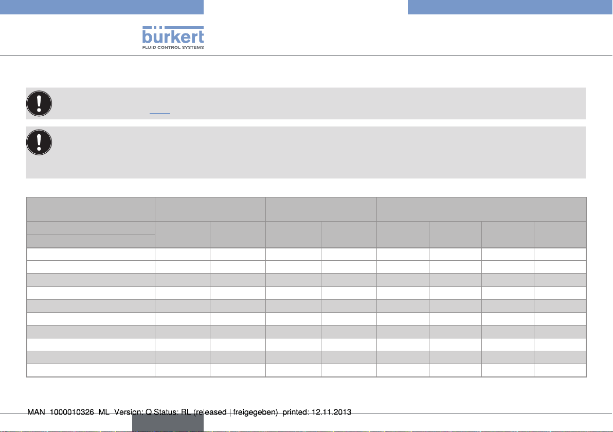
6.1. Conditions of use
Fluid
temperature
Ambient
temperature
Pressure
class
6.2. Available certificates
• Certificate 3.1, S020 in stainless steel only
• Certificate 2.2
• Surface roughness certificate
• Calibration certificate
• FDA approval (with EPDM seal), S020 in stainless steel only
depends on the device inserted and the material
from which the S020 fitting is made. Refer to the
operating instructions for the device and to the temperature/fluid pressure dependency curve in Fig. 5.
If the ranges are different, use the most restrictive
range.
depends on the device inserted into the S020.
Refer to the related operating instructions.
depends on the device inserted and the material
from which the S020 fitting is made. Refer to the
operating instructions for the device and to the temperature/fluid pressure dependency curve in Fig. 5.
If the pressure classes are different, take the lowest
value into account.
8
English
Page 9
Type S020
Technical data
6.3. General technical data
6.3.1. Diameters available
The diameters available depend on the design of the S020 fitting.
Consult the technical data sheets for the S020 fittings and
the device inserted to determine the appropriate DN.
Table 1: Diameters available depending on the design of the fitting
Design of the S020 DN available
T fittings for measuring devices with
a G2'' nut
T fittings for measuring devices with
a clamp process connection
Welding socket with radius, for measuring devices with a G2'' nut
Plastic fusion spigot DN65 to DN400
Screw-on
1)
Welding socket for measuring
devices with clamp connection
Saddle
1)
1)
Only for the flow measurement.
DN6 to DN65
DN32 to DN100
DN50 to DN350
DN100 to DN400
DN32 to DN100
DN50 to DN200
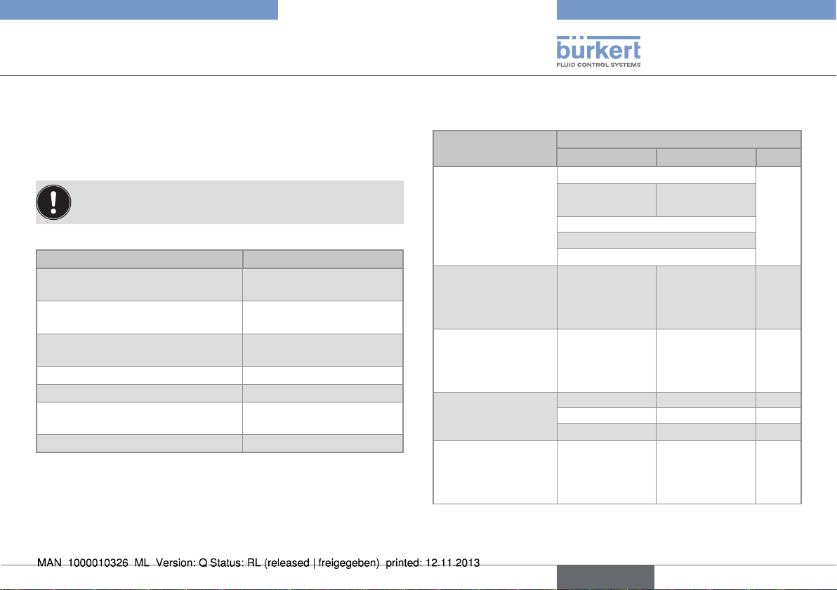
6.3.2. Materials
Table 2: Materials depending on the design of the S020 fitting
Design of the S020 Materials
Body Adapter Seal
T fittings for measuring devices with a
G2'' nut
T fittings for measuring devices with
a clamp process
connection
Welding socket with
radius, for measuring
devices with a G2''
nut
Fusion spigot
Welding socket
for measuring
devices with clamp
connection
Stainless steel (316L - 1.4404) FKM
Brass Stainless steel
(316L - 1.4404)
or
EPDM
PVC
PP
PVDF
Stainless steel
- -
(316L )
Stainless steel
- -
(316L - 1.4404)
PE - PP - PVDF - -
Stainless steel
- -
(316L )
English
9
Page 10
Type S020
Technical data
Screw-on
PVC - -
PE - -
PP - Saddle PP PVC EPDM
Measurement
chamber
Stainless steel
(316L - 1.4404)
- -
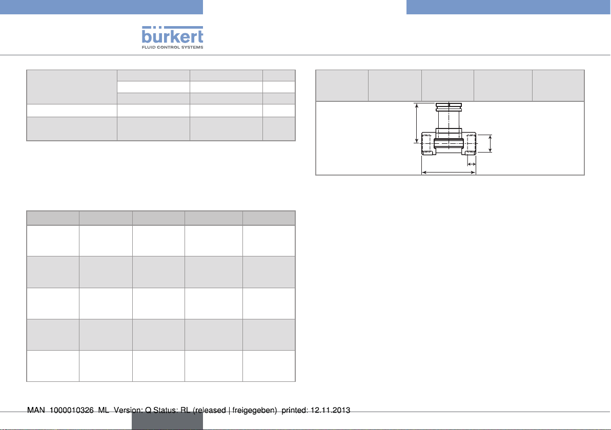
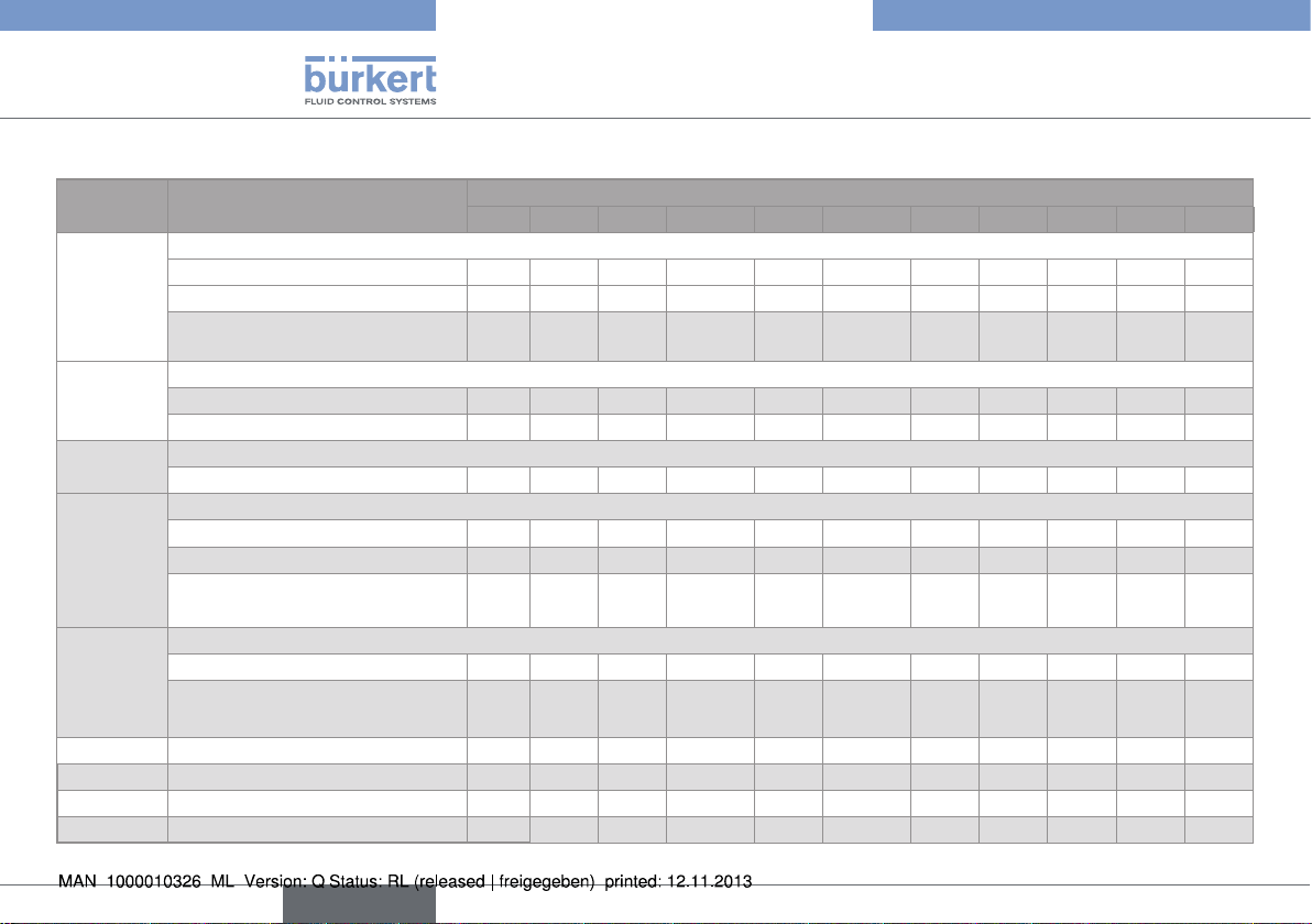
6.3.3. Dimensions of T fittings
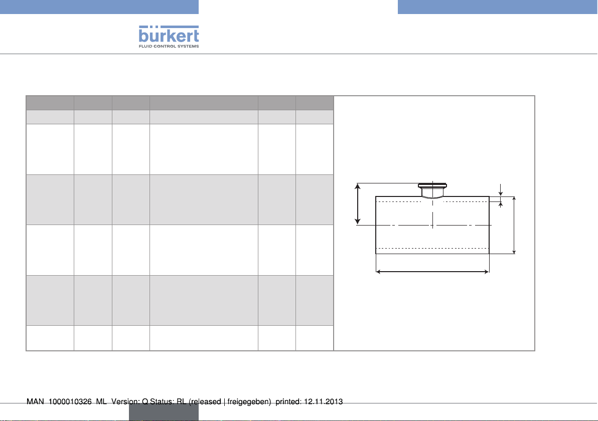
Table 3: Dimensions of the S020 fitting with internal thread
connections acc. to G, Rc or NPT, in stainless steel or
brass, for measuring devices with a G2'' nut
DN [mm] P [mm] A [mm] D [inch] L [mm]
15 80.3 84.0 G 1/2
NPT 1/2
Rc 1/2
20 77.8 94.0 G 3/4
NPT 3/4
Rc 3/4
25 78.0 104.0 G 1
NPT 1
Rc 1
32 81.6 119.0 G 1 1/4
NPT 1 1/4
Rc 1 1/4
40 85.4 129.0 G 1 1/2
NPT 1 1/2
Rc 1 1/2
16.0
17.0
15.0
17.0
18.3
16.3
23.5
18.0
18.0
23.5
21.0
21.0
23.5
20.0
19.0
50 91.5 148.5 G 2
NPT 2
Rc 2
P
L
A
27.5
24.0
24.0
D
10
English
Page 11
Type S020
Technical data
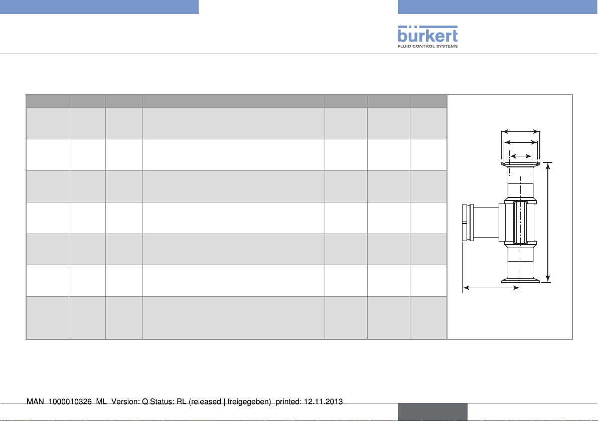
Table 4: Dimensions of the S020 fitting with external thread
connections acc. to G, in stainless steel, brass (DN15 to
50) or PVC (DN6 and 8 only), for measuring devices with
a G2'' nut
DN
[mm]
6 75.3 90.0 G 1/2 14.0
8 75.3 90.0 G 1/2 14.0
15 80.3 84.0 G 3/4 11.5
20 77.8 94.0 G 1 13.5
25 78.0 104.0 G 1 1/4 14.0
32 81.6 119.0 G 1 1/2 18.0
40 85.4 129.0 M55 x 2 19.0
50 91.5 148.5 M64 x 2 20.0
P
[mm]
A
[mm]
D
[inch]
L
[mm]
P
D
L
A
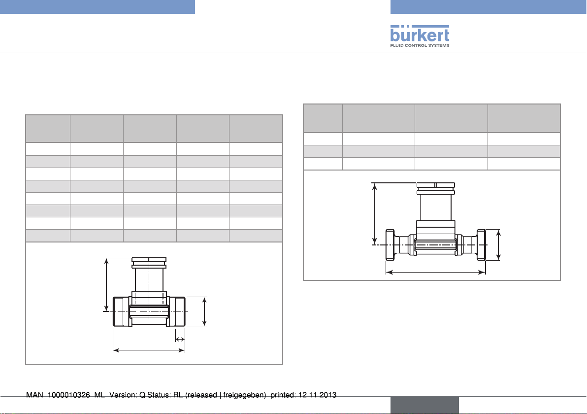
Table 5: Dimensions of the S020 fitting with external thread
connections acc. to SMS 1145, in stainless steel, for
measuring devices with a G2'' nut
DN
[mm]P[mm]
25 77.8 130 Rd40 x 1/6"
40 81.6 164 Rd60 x 1/6"
50 85.4 173 Rd70 x 1/6"
A
[mm]
D
[inch]
P
D
A
English
11
Page 12
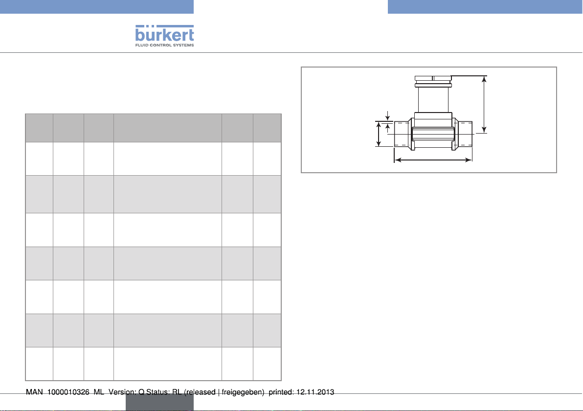
Table 6: Dimensions of the S020 fitting with welding end
connections acc. to EN ISO 1127 / ISO 4200, SMS 3008
or BS 4825/ASME BPE, in stainless steel, for measuring
devices with a G2'' nut
DN
[mm]P[mm]A[mm]
15 80.3
-
-
20 77.8
-
83.3
25 78.0
77.8
77.8
32 81.6
-
78.0
40 85.4
81.6
81.6
50 91.5
85.4
85.4
65 -
91.5
91.5
84.0
-
-
94.0
-
84.0
104.0
94.0
94.0
119.0
-
104.0
129.0
119.0
119.0
148.5
128.0
128.0
-
147.0
147.0
Standard D
EN ISO 1127 / ISO 4200
SMS 3008
ASME BPE
EN ISO 1127 / ISO 4200
SMS 3008
ASME BPE
EN ISO 1127 / ISO 4200
SMS 3008
BS 4825 / ASME BPE
EN ISO 1127 / ISO 4200
SMS 3008
BS 4825 / ASME BPE
EN ISO 1127 / ISO 4200
SMS 3008
BS 4825 / ASME BPE
EN ISO 1127 / ISO 4200
SMS 3008
BS 4825 / ASME BPE
EN ISO 1127 / ISO 4200
SMS 3008
BS 4825 / ASME BPE
[mm]s[mm]
21.30
-
-
26.90
-
19.05
33.70
25.00
25.40
42.40
-
32.00
48.30
38.00
38.10
60.30
51.00
50.80
-
63.50
63.50
1.60
-
-
1.60
-
1.65
2.00
1.20
1.65
2.00
-
1.65
2.00
1.20
1.65
2.60
1.20
1.65
-
1.60
1.65
Type S020
Technical data
s
H
P
�A
12
English
Page 13
Type S020
Technical data
Table 7: Dimensions of the S020 fitting with Clamp connections acc. to ISO (for pipes according to EN ISO 1127 / ISO 4200), SMS 3017/
ISO 2852
DN [mm]
P [mm] A [mm] Standard D2 [mm] D1 [mm] D [mm]
15 80.3
-
-
20 77.8
-
80.3
25 78.0
77.8
77.8
32 81.6
-
-
40 85.4
81.6
81.6
50 91.5
85.4
85.4
65 -
91.5
91.5
1)
Available with an internal roughness of Ra = 0.8 μm
1)
or BS 4825/ASME BPE1), in stainless steel, for measuring devices with a G2'' nut
130.0
-
-
150.0
-
119.0
160.0
129.0
129.0
180.0
-
-
200.0
161.0
161.0
230.0
192.0
192.0
-
216.0
216.0
ISO (pipe EN ISO 1127 / ISO 4200)
SMS 3017 / ISO 2852
ASME BPE
ISO (pipe EN ISO 1127 / ISO 4200)
SMS 3017 / ISO 2852
ASME BPE
ISO (pipe EN ISO 1127 / ISO 4200)
SMS 3017 / ISO 2852
BS 4825 / ASME BPE
ISO (pipe EN ISO 1127 / ISO 4200)
SMS 3017 / ISO 2852
BS 4825 / ASME BPE
ISO (pipe EN ISO 1127 / ISO 4200)
SMS 3017 / ISO 2852
BS 4825 / ASME BPE
ISO (pipe EN ISO 1127 / ISO 4200)
SMS 3017 / ISO 2852
BS 4825 / ASME BPE
ISO (pipe EN ISO 1127 / ISO 4200)
SMS 3017 / ISO 2852
BS 4825 / ASME BPE
18.10
-
-
23.70
-
15.75
29.70
22.60
22.10
38.4
-
-
44.3
35.6
34.8
55.1
48.6
47.5
-
60.3
60.2
27.5
-
-
43.5
-
19.6
43.5
43.5
43.5
43.5
-
-
56.5
43.5
43.5
70.5
56.5
56.5
-
70.5
70.5
34.0
-
-
50.5
-
25.0
50.5
50.5
50.5
50.5
-
-
64.0
50.5
50.5
77.5
64.0
64.0
-
77.5
77.5
D
D1
D2
A
P
English
13
Page 14
Type S020
Technical data
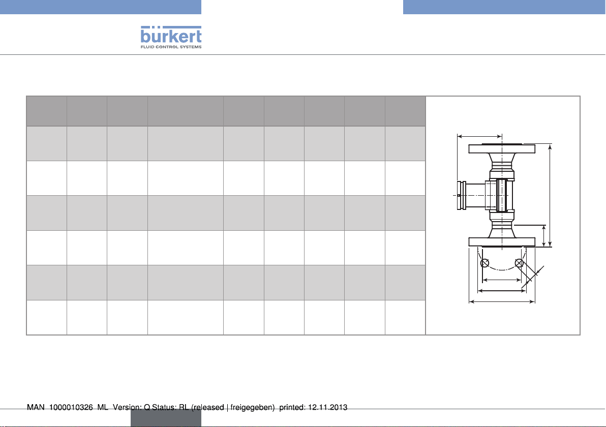
Table 8: Dimensions of the S020 fitting with flange connections acc. to EN1092-1 (ISO PN16), ANSI B16-5-1988 or JIS 10K, in stainless
steel, for measuring devices with a G2'' nut
DN
[mm]P[mm]A[mm]
15 80.3
80.3
80.3
20 77.8
77.8
77.8
25 78.0
78.0
78.0
32 81.6
81.6
81.6
40 85.4
85.4
85.4
50 91.5
91.5
91.5
130.0
130.0
152.0
150.0
150.0
178.0
160.0
160.0
216.0
180.0
180.0
229.0
200.0
200.0
241.0
230.0
230.0
267.0
Standard L
DIN
ANSI
JIS
DIN
ANSI
JIS
DIN
ANSI
JIS
DIN
ANSI
JIS
DIN
ANSI
JIS
DIN
ANSI
JIS
[mm]Z[mm]D2[mm]D1[mm]D[mm]
23.5
23.5
23.5
28.5
28.5
28.5
28.5
28.5
28.5
31.0
31.0
31.0
36.0
36.0
36.0
41.0
41.0
41.0
4x14.0
4x15.8
4x15.0
4x14.0
4x15.8
4x15.0
4x14.0
4x15.8
4x19.0
4x18.0
4x15.8
4x19.0
4x18.0
4x15.8
4x19.0
4x18.0
4x19.0
4x19.0
45.0
34.9
51.0
58.0
42.9
56.0
68.0
50.8
67.0
78.0
63.5
76.0
88.0
73.0
81.0
102.0
92.1
96.0
65.0
60.3
70.0
75.0
69.8
75.0
85.0
79.4
90.0
100.0
88.9
100.0
110.0
98.4
105.0
125.0
120.6
120.0
95.0
89.0
95.0
105.0
99.0
100.0
115.0
108.0
125.0
140.0
117.0
135.0
150.0
127.0
140.0
165.0
152.0
155.0
P
A
L
D2
Z
D1
D
14
English
Page 15
Type S020
A
Technical data
Table 9: Dimensions of the S020 fitting with true union connections acc. to DIN 8063, ASTM D 1785/76 or JIS K in PVC, acc. to
DIN 16962 in PP or acc. to ISO 10931 in PVDF, for measuring devices with a G2'' nut
DN
[mm]P[mm]D[mm]ADIN/ISO ASTM JISD1DIN/ISO ASTM JIS
15
15
20
20
25
25
1)
1)
1)
80.4
81.44374
77.8
81.45374
78.0
81.46074
128
148
144
154
160
160
130.0-129
-
145.6-145
-
161.4-161
-
20
20
25
25
32
32
21.3-18.40-90
26.7-26.45-100
33.4-32.55-110
A2
[mm]A1[mm]
11096116
106
110
116
116
110
116
D
D1
A2
A1
A
32 81.4 74 168 170.0 169 40 42.2 38.60 110 116
40 85.2 83 188 190.2 190 50 48.3 48.70 120 127
50 91.5 103 212 213.6 213 63 60.3 60.80 130 136
1)
Specific fitting for analytical sensors
P
Table 10: Dimensions of the S020 fitting with spigot connections acc. to DIN 8063 in PVC, acc. to DIN 16962 in PP or acc. to ISO 10931 in
PVDF, for measuring devices with a G2'' nut
DN
[mm]
15 80.4 17.5 90 85 20 16.5 14
P
[mm]
H
[mm]
A [mm]
DIN 8063 DIN 16962
ISO 10931
D [mm] L [mm]
DIN 8063 DIN 16962
ISO 10931
PH
20 77.8 17.5 100 92 25 20 16
25 78.0 21.5 110 95 32 23 18
D
32 81.4 27.5 110 100 40 27.5 20
40 85.2 31.5 120 106 50 30 23
50 91.5 39.5 130 110 63 37 27
L
English
15
Page 16
Type S020
P
Technical data
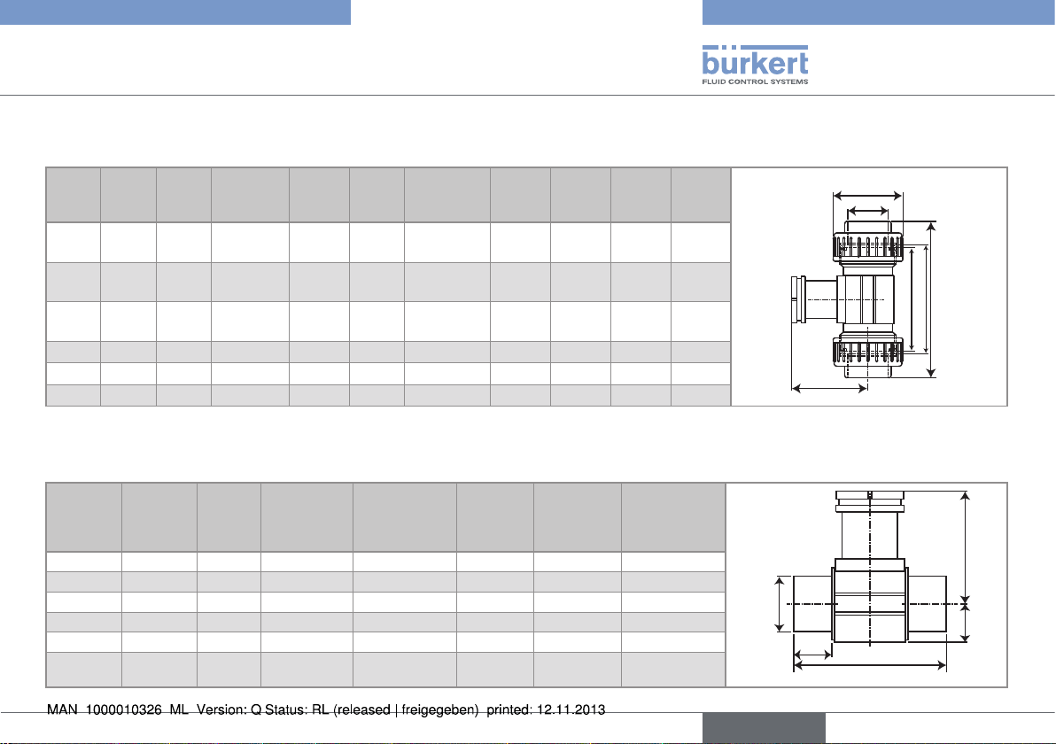
Table 11: Dimensions of the S020 fitting with welding end connections acc. to EN ISO 1127 / ISO 4200, SMS 3008, BS 4825/ASME BPE
or DIN 11850 range 2, for measuring devices with a clamp connection
DN [mm] P [mm] A [mm] Standard D [mm] S [mm]
32 - 130 EN ISO 1127 / ISO 4200 42.4 2
40 - 130 EN ISO 1127 / ISO 4200 48.3 2
42.5 110 SMS 3008 38 1.2
43.7 120.6 BS 4825 / ASME BPE 38.1 1.65
- 120 DIN 11850 range 2 41 1.5
50 - 180 EN ISO 1127 / ISO 4200 60.3 2
49.3 164 SMS 3008 51 1.2
S
50.6 146 BS 4825 / ASME BPE 50.8 1.65
- 160 DIN 11850 range 2 53 1.5
D
65 - 220 EN ISO 1127 / ISO 4200 76.1 2
54.4 210 SMS 3008 63.5 1.5
55.4 158.8 BS 4825 / ASME BPE 63.5 1.65
- 210 DIN 11850 range 2 70 2
A
80 - 260 EN ISO 1127 / ISO 4200 88.9 2.3
60.7 220 SMS 3008 76.1 1.6
62 171.5 BS 4825 / ASME BPE 76.2 1.65
- 260 DIN 11850 range 2 85 2
100 73.8
77.1
209.6 BS 4825 / ASME BPE 101.6 2.11
310 DIN 11850 range 2 104 2
16
English
Page 17
Type S020
Technical data
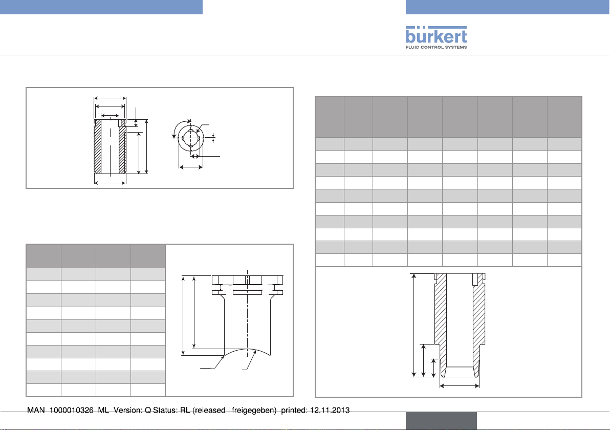
6.3.4. Dimensions of spigots
ø 49
ø 45
ø27.6
G1-1/2"
Fig. 1: Dimensions of screw-ons DN65 to DN400, in PVC, PE or PP
(in mm), for measuring devices with a G2'' nut
Table 12: Dimensions of the welding sockets with radius, in
stainless steel, for measuring devices with a G2" nut
DN
[mm]A[mm]B[mm]R[mm]
50 56.6 61.6 30.2
65 54.5 58.6 36.7
80 53.1 56.4 44.5
100 50.7 53.2 57.2
125 48.2 50.3 70.7
150 45.7 47.4 84.2
200 41.0 42.3 109.6
250 73.6 74.7 136.6
300 67.8 68.7 162.0
350 63.9 64.7 177.8
11.5
73
93
90°
B
45
A +0.1
R4 (4x)
3
16.2
R0.5
R
Table 13: Dimensions of the fusion spigots, in PE, PP or PVDF, for
measuring devices with a G2" nut
DN
[mm]H[mm]PEH1
[mm]
H2
[mm]
PP
H1
[mm]
H2
[mm]
PVDF
H1
[mm]
H2
[mm]
65 72.5 13 - 13 - 10.4 80 72.5 15.6 - 15.6 - 12.5 100 72.5 19 5 19 5 15.2 6
125 102 24.2 8 - - - 150 102 27.7 10 27.7 10 - 200 102 38.9 16 38.9 16 - 250 102 48.4 21 48.4 21 - 300 102 54.5 24 54.5 24 - 350 102 61.3 28 61.3 28 - 400 102 69.1 31.5 - - - -
H
H1
H2
ø39
English
17
Page 18
Type S020
H
Ø
50,5
H
Technical data
Table 14: Dimensions of the welding sockets acc. to EN ISO 1127 / ISO 4200, SMS 3008, BS 4825/ASME BPE or DIN 11850 range 2, for
measuring devices with a clamp connection
DN [mm] H [mm] Standard
32 - ISO 4200
40 21.7 SMS 3008
1
23.7 BS 4825 / ASME BPE
- DIN 11850 range 2
- ISO 4200
50 21.7 SMS 3008
23.7 BS 4825 / ASME BPE
- DIN 11850 range 2
Welding socket acc. to SMS 3008, DIN 11850 Range 2 and ISO 4002
- ISO 4200
65 19.7 SMS 3008
19.7 BS 4825 / ASME BPE
- DIN 11850 range 2
- ISO 4200
1
Ø 50.5
80 19.7 SMS 3008
19.7 BS 4825 / ASME BPE
- DIN 11850 range 2
- ISO 4200
100 19.7 SMS 3008
19.7 BS 4825 / ASME BPE
19.7 DIN 11850 range 2
Welding socket acc. to BS 4825/ASME BPE
18
English
Page 19
Type S020
Technical data
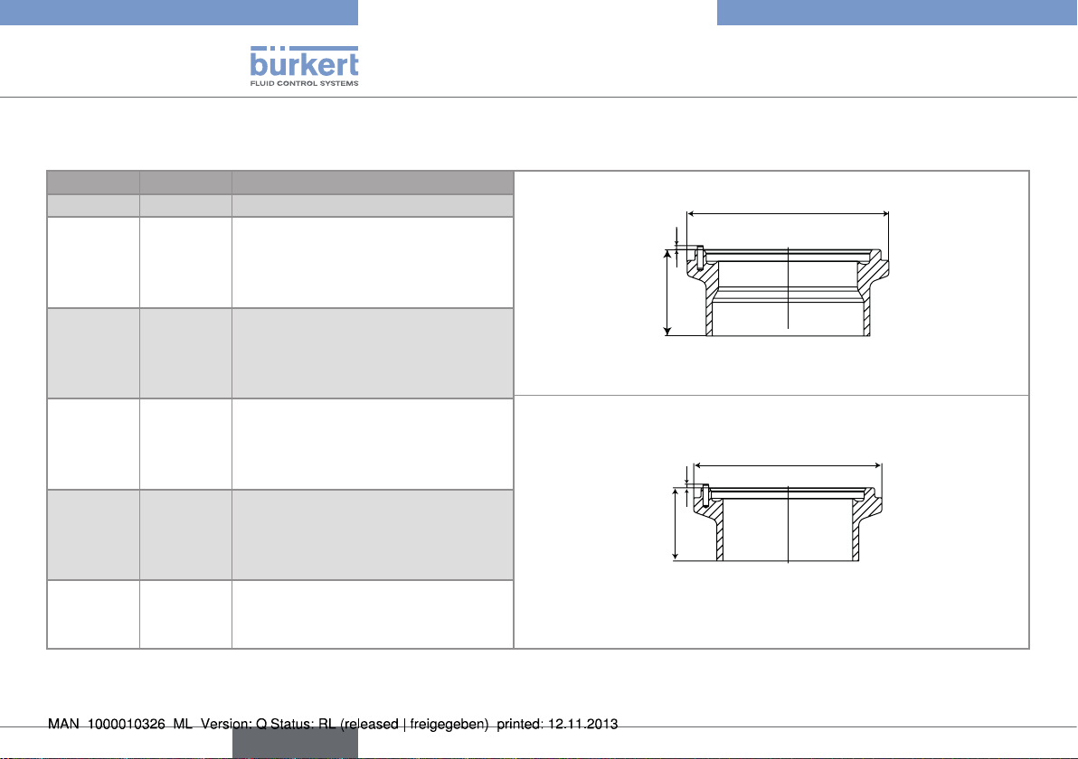
6.3.5. Dimensions of the saddles
Table 15: Dimensions of the saddles in PP/PVC
DN
[mm]D[mm]P[mm]D1[mm]H[mm]
50 116 116.0 63 155.0
65 129 115.0 75 160.0
80 144 119.0 90 171.0
100 166 124.0 110 187.0
110 181 120.0 125 191.0
125 196 127.0 140 205.0
150 216 137.0 160 225.0
180 266 161.0 200 271.0
200 290 173.0 225 297.0
D1
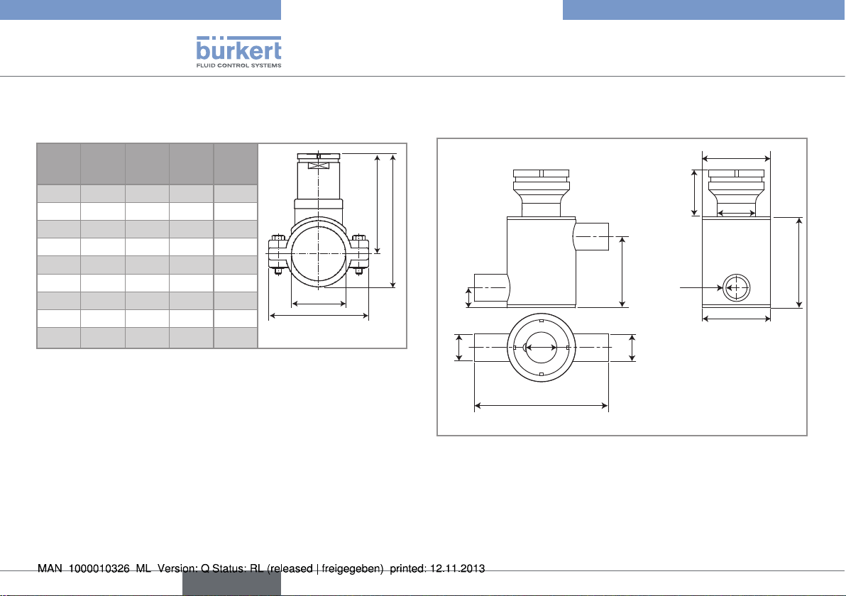
6.3.6. Dimensions of the measurement
chamber
ø 60.3
P
H
62.6
D
17.6
G 1/2
ø 27
G 1/2
118
Fig. 2: Dimensions of the measurement chamber (in mm)
41
ø 33.6
80.2
2.70
ø 60
19
English
Page 20
Type S020
Technical data
6.4. K factors
6.4.1. Terms of reference
The K factors have all been determined under the following terms
of reference: fluid = water, water and room temperatures of 20°C,
minimum upstream and downstream distances respected, appropriate pipe dimensions.
6.4.2. Calculation of K factors (in pulse/
litre) for saddles, fusion spigots,
welding sockets with radius or
screw-ons
The calculation does not apply to T fittings or welding
sockets for measuring devices with a clamp connection.
In addition to the terms of reference mentioned above, the K factors
for saddles, fusion spigots, welding sockets with radius and screwons have been determined as a function of the external diameter
(D
) and the wall thickness (s
material
tables.
) of the pipe given in the
material
→ When the dimensions of the pipe are slightly different from
dimensions D and s given in the tables, recalculate the K factor
using one of the following formulae:
These formulae can only be applied if the dimensions of the
pipe vary by +/-5% compared with the theoretical dimensions given in the tables.
2
d
Kn = Kt x
t
2
d
n
Fig. 3: Fitting used with a paddle-wheel flowmeter
2
d
Kn = Kt x
n
2
d
t
Fig. 4: Fitting used with an electromagnetic flowmeter
Kn = recalculated K factor
= K factor given in the table
K
t
= D
d
t
= internal diameter of the pipe
d
n
material
- 2s
= theoretical internal diameter of the pipe
material
calculated using the values D
s
given in the tables, for each fitting
material
material (D
the pipe and s
pipe)
= external diameter of
material
= thickness of the
material
material
and
20
English
Page 21
Type S020
Technical data
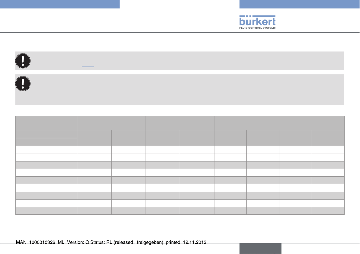
6.4.3. K factors (in pulse/litre) for T fittings used with a 8041 or 8045 with a G2'' nut
We advise not to use a type 8041 or 8045 measuring device in an S020 fitting in brass as drifts in measurement may occur.
If the measuring device does not automatically convert the K factor, use the following conversion formulae before setting the parameters of the device:
• K factor in pulse/US gallon = K factor in pulse/litre x 3.785
• K factor in pulse/UK gallon = K factor in pulse/litre x 4.546
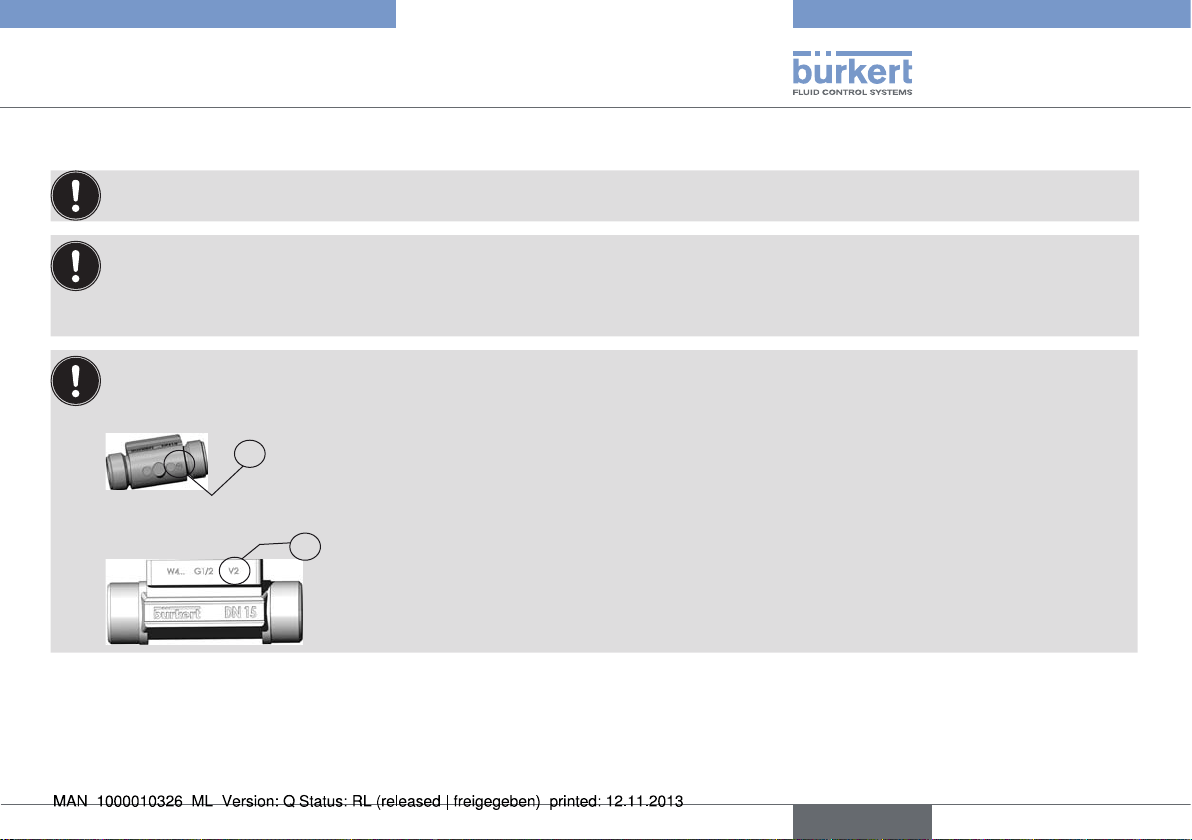
Two versions of the S020 in DN15 and DN20 exist, having different K factors.
Only version 2, identified by the "v2" marking, is available from March 2012. The "v2" marking can be found:
• on the bottom of the DN15 fitting in plastic:
V2
• on the side of the DN15 or DN20 fitting in metal:
V2
English
21
Page 22
Type S020
Technical data
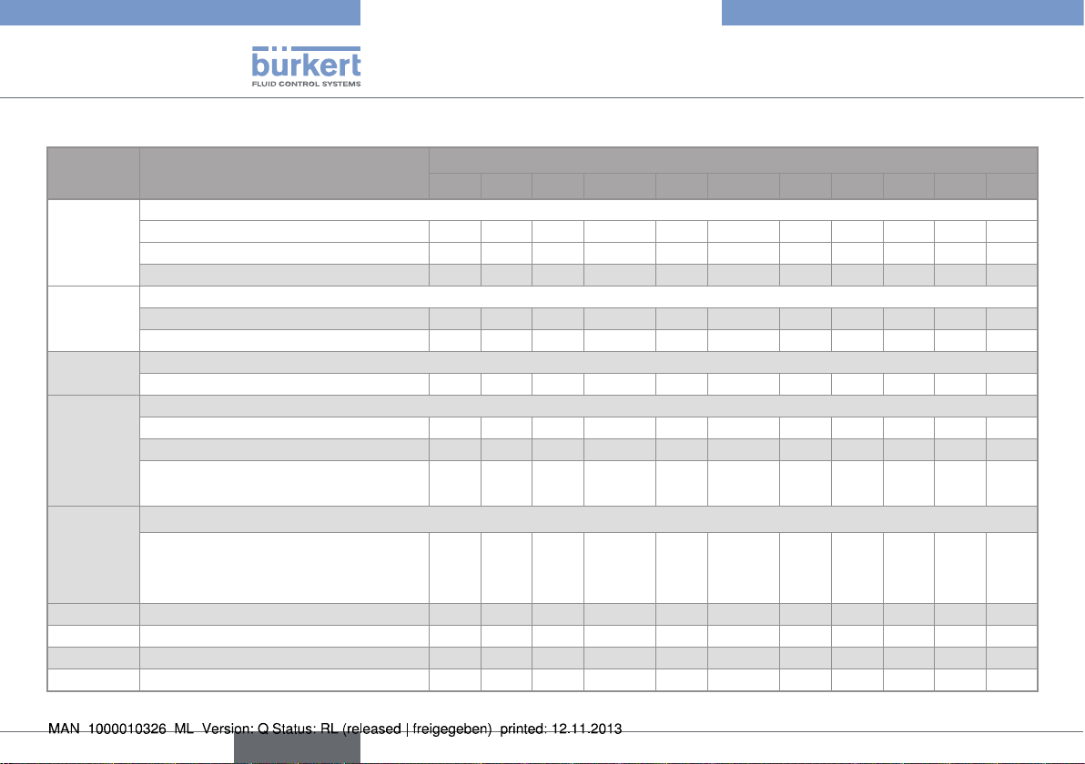
Table 16: K factors depending on the connections and standards and materials of the T fittings used with a 8041 or 8045 with G2" nut
Material Type of connection and standard
Stainless
steel
Stainless
steel
Stainless
steel
Stainless
steel
Stainless
steel
Brass all - - - - 1,98 - 2,85 4,32 6,68 11,3 PVC all 0,310 0,470 1,33 1,33 1,45 - 2,26 4,29 7,30 12,5 PP all - - 1,29 1,37 1,44 - 2,21 4,30 7,16 12,2 PVDF all - - 1,21 1,22 1,37 - 2,04 4,03 6,88 11,5 -
welding ends
• acc. to SMS 3008 - - - - - - 1,98 - 4,32 6,68 11,3
• acc. to BS 4825 / ASME BPE - - - - 1,69 1,75 1,98 2,85 4,32 6,68 11,3
• acc. to EN ISO 1127 / ISO 4200 - - 1,69 1,75 1,98 - 2,85 4,32 6,68 11,3 external threads
• acc. to SMS 1145 - - - - - - 1,98 - 4,32 6,68 -
• G 0,355 0,530 1,69 1,75 1,98 - 2,85 4,32 6,68 11,3 internal threads
• G, Rc, NPT 0,355 0,530 1,69 1,75 1,98 - 2,85 4,32 6,68 11,3 Clamp
• acc. to SMS 3017 / ISO 2852 - - - - - - 1,98 - 4,32 6,68 11,3
• acc. to BS 4825 / ASME BPE - - - - 1,69 1,75 1,98 - 4,32 6,68 11,3
• acc. to ISO (for pipes acc. to
EN ISO 1127 / ISO 4200)
flanges
• acc. to EN1092-1 (ISO PN16)
• acc. to ANSI B16-5-1998
• acc. to JIS 10K
K factor [Pulse/litre]
DN6 DN8 DN15 DN15 v2 DN20 DN20 v2 DN25 DN32 DN40 DN50 DN65
- - 1,69 1,75 1,98 - 2,85 4,32 6,68 11,3 -
- - 1,69 1,75 1,98 - 2,85 4,32 6,68 11,3 -
22
English
Page 23
Type S020
Technical data
6.4.4. K factors (in pulse/litre) for T
fittings and welding sockets used
with a 8041 or a 8045 with clamp
connection
Table 17: K factors of the T fittings for measuring devices with clamp
connection
Type of connection
and standard
acc. to SMS 3008 5.23 10.4 15.9 24.7 acc. to BS 4825 /
ASME BPE
acc. to DIN 11850
range 2
acc. to ISO 4200 - - - - -
DN40 DN50 DN65 DN80 DN100
5.33 10.4 16.7 25.7 50.3
- - - - 52.7
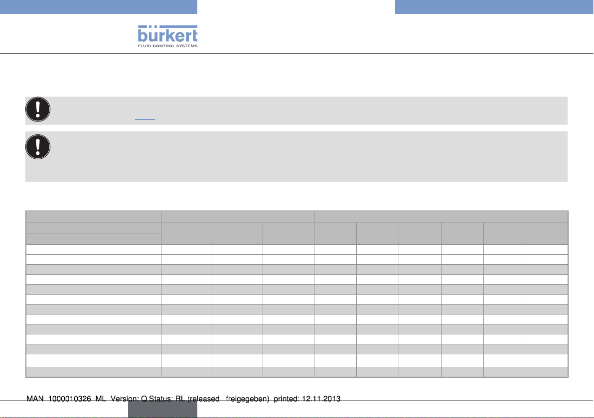
6.4.5. K factors (in pulse/litre) for T fittings
used with a 8020, 8024, 8025 or
8026
If the measuring device does not automatically convert the K
factor, use the following conversion formulae before setting
the parameters of the device:
• K factor in pulse/US gallon = K factor in pulse/litre x 3.785
• K factor in pulse/UK gallon = K factor in pulse/litre x 4.546
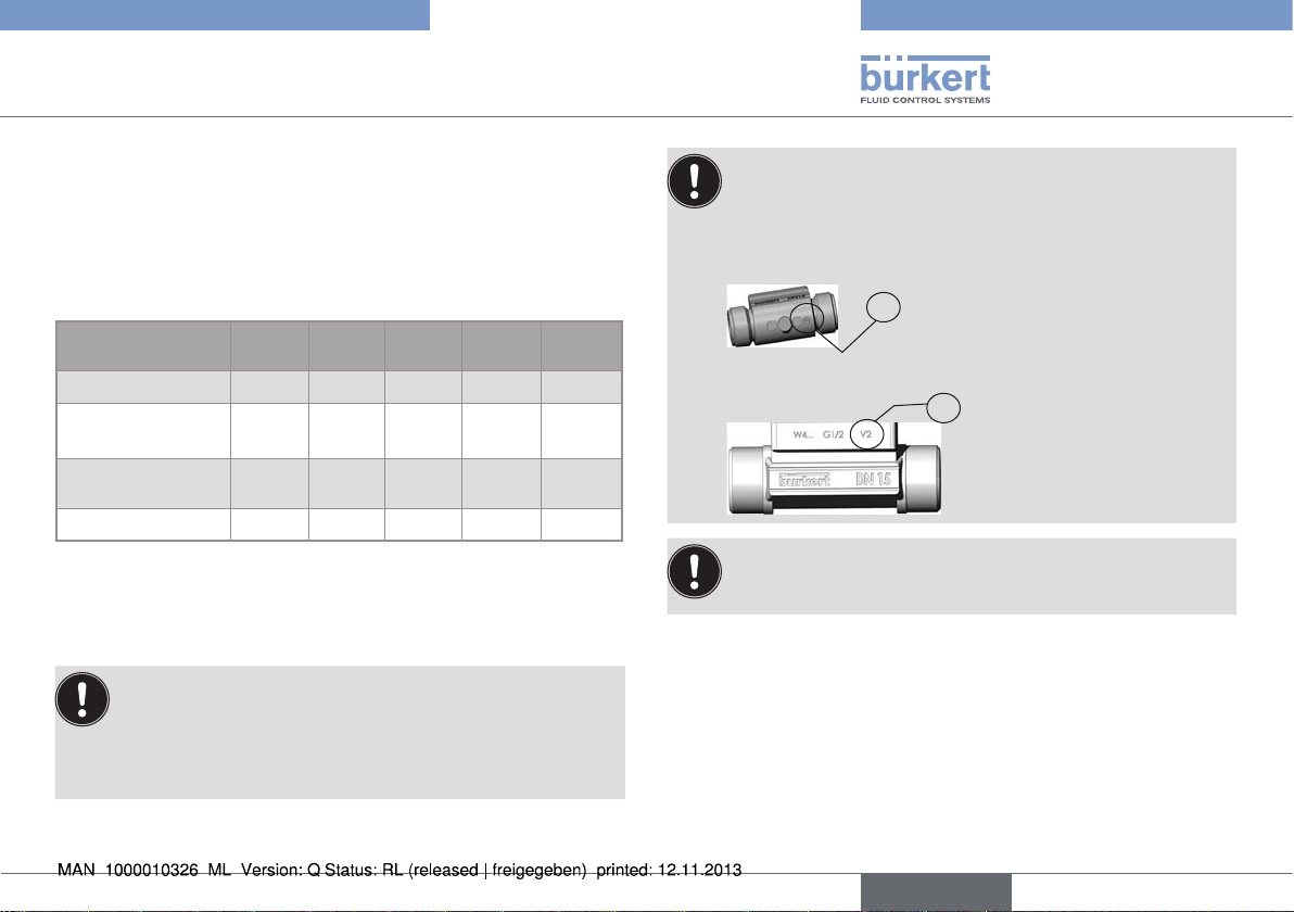
Two versions of the S020 in DN15 and DN20 exist, having
different K factors.
Only version 2, identified by the "v2" marking, is available
from March 2012. The "v2" marking can be found:
• on the bottom of the DN15 fitting in plastic:
V2
• on the side of the DN15 or DN20 fitting in metal:
V2
Do not use a fitting S020 in sizes DN6, DN8, DN15, DN15
Version 2 (V2) or DN20 Version 2 (V2) with a paddle-wheel
flowmeter types 8020, 8024, 8025, 8026.
English
23
Page 24
Type S020
Technical data
Table 18: K factors depending on the connections and standards and materials of the T fittings used with a 8020, 8024, 8025 or 8026
Material Type of connection and standard
Stainless
steel
Stainless
steel
Stainless
steel
Stainless
steel
Stainless
steel
Brass all - - - - 64,0 - 48,3 30,9 19,5 11,2 PVC all - - - - 81,1 - 56,6 29,9 18,6 10,7 PP all - - - - 75,1 - 53,6 29,0 17,4 10,3 PVDF all - - - - 81,2 - 60,3 31,9 19,4 11,1 -
welding ends
• acc. to SMS 3008 - - - - - - 64,0 - 30,9 19,5 11,2
• acc. to BS 4825 / ASME BPE - - - - - - 64,0 48,3 30,9 19,5 11,2
• acc. to EN ISO 1127 / ISO
4200
external threads
• acc. to SMS 1145 - - - - - - 64,0 - 30,9 19,5 -
• G - - - - 64,0 - 48,3 30,9 19,5 11,2 -
internal threads
• G, Rc, NPT - - - - 64,0 - 48,3 30,9 19,5 11,2 -
Clamp
• acc. to SMS 3017 / ISO 2852 - - - - - - 64,0 - 30,9 19,5 11,2
• acc. to BS 4825 / ASME BPE - - - - - - 64,0 - 30,9 19,5 11,2
• acc. to ISO (for pipes acc. to
EN ISO 1127 / ISO 4200)
flanges
• acc. to EN1092-1 (ISO PN16) - - - - 64,0 - 48,3 30,9 19,5 11,2 -
• acc. to ANSI B16-5-1998
• acc. to JIS 10K
K factor [Pulse/litre]
DN6 DN8 DN15 DN15 v2 DN20 DN20 v2 DN25 DN32 DN40 DN50 DN65
- - - - 64,0 - 48,3 30,9 19,5 11,2 -
- - - - 64,0 - 48,3 30,9 19,5 11,2 -
- - - - 64,0 - 48,3 30,9 19,5 11,2
24
English
Page 25
Type S020
Technical data
6.4.6. K factors (in pulse/litre) for saddles
When the dimensions of the pipe are slightly different from dimensions D and s given in the table, recalculate the K factor using one of
the formulae in chap. 6.4.2.
If the measuring device does not automatically convert the K factor, use the following conversion formulae before setting the parameters of the device:
• K factor in pulse/US gallon = K factor in pulse/litre x 3.785
• K factor in pulse/UK gallon = K factor in pulse/litre x 4.546
Table 19: K factors, external diameters and theoretical cross-sections of saddles
Measuring device
inserted
Material of the pipe
DN
50 14,2 (L) 15,6 (L) 10,4 (L) 9,28 (L) 63 4,7 63 5,8
65 11,2 (L) 12,3 (L) 14,5 (L) 12,9 (L) 75 5,5 75 6,9
80 7,37 (L) 7,80 (L) 21,3 (L) 20,4 (L) 90 6,6 90 8,2
100 4,83 (L) 5,29 (L) 33,0 (L) 30,4 (L) 110 8,1 110 10
110 3,45 (L) - 44,7 (L) - 125 9,2 - 125 2,55 (L) 3,10 (L) 63,7 (L) 52,1 (L) 140 10,3 140 12,8
150 1,67 (L) 2,03 (L) 137 (L) 78,8 (L) 160 6,2 160 14,6
180 1,08 (L) 1,37 (L) 197 (L) 116 (L) 200 9,6 200 18,2
200 0,80 (L) 1,07 (L) 290 (L) 147 (L) 225 8,6 225 20,5
(L): long sensor version
8020, 8024, 8025, 8026 8041, 8045 External diameters and theoretical cross-sections
PVC PE / PP PVC PE / PP
D
PVC
[mm]
s
PVC
[mm]
D
PP
[mm]
s
PP
[mm]
English
25
Page 26
Type S020
Technical data
6.4.7. K factors (in pulse/l) of the fusion spigots and welding sockets with radius for
measuring devices with a G2'' nut
When the dimensions of the pipe are slightly different from dimensions D and s given in the table, recalculate the K factor using one of
the formulae in chap. 6.4.2.
If the measuring device does not automatically convert the K factor, use the following conversion formulae before setting the parameters of the device:
• K factor in pulse/US gallon = K factor in pulse/litre x 3.785
• K factor in pulse/UK gallon = K factor in pulse/litre x 4.546
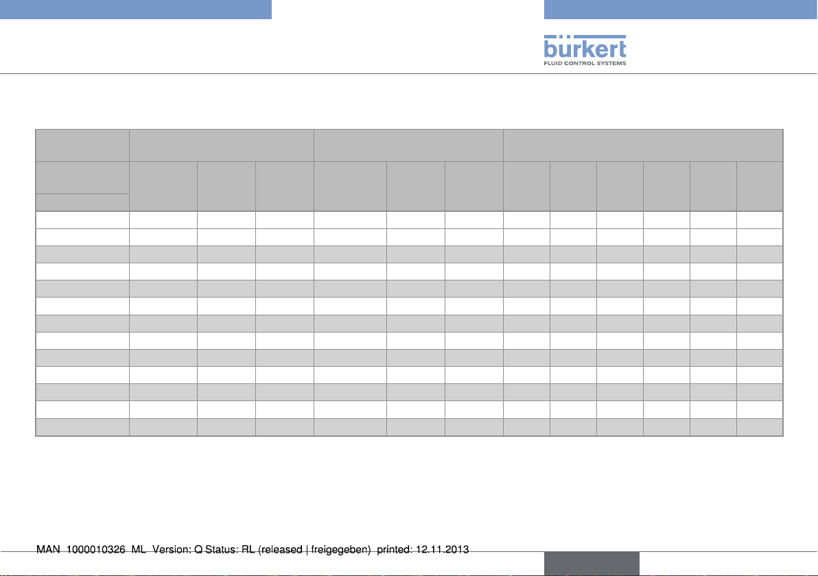
Table 20: K factors, external diameters and theoretical cross sections of the welding sockets with radius, for measuring devices with a G2''
nut, and of the fusion spigots in plastic, used with a 8020, 8024, 8025 or 8026
Measuring device inserted 8020, 8024, 8025, 8026 External diameters and theoretical cross-sections
Material of the pipe
DN
50 13,0 (C) - - 60,3 2,0 - - - 65 7,86 (C) 8,32 (C) 5,53 (C) 76,1 2,9 75 6,9 75 2,5
80 5,52 (C) 5,49 (C) 3,65 (C) 88,9 3,2 90 8,2 90 2,8
100 3,20 (C) 3,51 (C) 2,34 (C) 114,3 3,6 110 10 110 3,5
110 - - - - - - - - 125 2,00 (C) 2,66 (L) - 139,7 4 140 12,8 - 150 1,32 (C) 2,12 (L) - 168,3 4,5 160 14,6 - 180 - - - - - 200 18,2 - 200 0,72 (C) 0,98 (L) - 219,1 6,3 225 20,5 - 250 0,50 (L) 0,63 (L) - 273 7,7 280 25,5 - 300 0,35 (L) 0,42 (L) - 323,9 9,5 315 28,7 - -
350 0,26 (L) 0,30 (L) - 355,6 10,1 355 32,3 - 400 - 0,23 (L) - - - 400 36,4 - -
Stainless
steel
PE / PP PVDF
D
steel
[mm]
s
steel
[mm]
D
PE/PP
[mm]
s
PE/PP
[mm]
D
PVDF
[mm]
s
PVDF
[mm]
26
English
Page 27
Type S020
Technical data
Table 21: K factors, external diameters and theoretical cross-sections of welding sockets with radius and fusion spigots, in plastic, used with a
8041 or a 8045 with G2'' nut
Measuring
device inserted
Material of the
pipe
DN
8041, 8045 with sensor in
stainless steel
Stainless
steel
PE / PP PVDF
8041, 8045 with sensor in PVDF
Stainless
steel
PE / PP PVDF
External diameters and theoretical
cross-sections
D
steel
[mm]
s
[mm]
steel
D
PE/PP
[mm]
s
PE/PP
[mm]
50 11,6 (C) - - 13,8 (C) - - 60,3 2,0 - - - -
65 20,0 (C) 17,8 (C) 24,1 (C) 24,0 (C) 21,3 (C) 28,9 (C) 76,1 2,9 75 6,9 75 2,5
80 28,5 (C) 25,6 (C) 40,8 (C) 33,2 (C) 30,7 (C) 48,9 (C) 88,9 3,2 90 8,2 90 2,8
100 49,2 (C) 38,1 (C) 70,5 (C) 60,5 (C) 45,7 (C) 84,5 (C) 114,3 3,6 110 10 110 3,5
110 - - - - - - - - - - - 125 78,0 (C) 81,7 (L) - 93,6 (C) 81,7 (L) - 139,7 4 140 12,8 - 150 98,4 (C) 103 (L) - 118 (C) 103 (L) - 168,3 4,5 160 14,6 - 180 - - - - - - - - 200 18,2 - 200 210 (C) 224 (L) - 252 (C) 224 (L) - 219,1 6,3 225 20,5 - 250 311 (L) 347 (L) - 311 (L) 347 (L) - 273 7,7 280 25,5 - 300 447 (L) 510 (L) - 447 (L) 510 (L) - 323,9 9,5 315 28,7 - 350 609 (L) 705 (L) - 609 (L) 705 (L) - 355,6 10,1 355 32,3 - 400 - 931 (L) - - 931 (L) - - - 400 36,4 - -
(C): short sensor version
(L): long sensor version
D
PVDF
[mm]
s
PVDF
[mm]
English
27
Page 28
Type S020
Technical data
6.4.8. K factors (in pulse/litre) for screw-ons
When the dimensions of your pipe are slightly different from dimensions D and s given in the table, recalculate the K factor using one
of the formulae in chap. 6.4.2.
If the measuring device does not automatically convert the K factor, use the following conversion formulae before setting the parameters of the device:
• K factor in pulse/US gallon = K factor in pulse/litre x 3.785
• K factor in pulse/UK gallon = K factor in pulse/litre x 4.546
Table 22: K factors, external diameters and theoretical cross-sections of screw-ons
Measuring device inserted 8020, 8024, 8025, 8026 8041, 8045
Material of the pipe
DN
PVC PP / PE PVC PP / PE
100 4,83 (L) 5,29 (L) 33,0 (L) 30,4 (L) 110 8,1 110 10
110 3,45 (L) - 44,7 (L) - 125 9,2 125 11,4
125 2,55 (L) 3,10 (L) 63,7 (L) 52,1 (L) 140 10,3 140 12,8
150 1,67 (L) 2,12 (L) 137 (L) 78,8 (L) 160 6,2 160 14,6
180 1,08 (L) 1,37 (L) 197 (L) 116 (L) 200 9,6 200 18,2
200 0,80 (L) 1,07 (L) 290 (L) 147 (L) 225 8,6 225 20,5
250 - 0,63 (L) - 347 (L) - - 280 25,5
300 - 0,42 (L) - 510 (L) - - 315 28,7
350 - 0,30 (L) - 705 (L) - - 355 32,3
400 - 0,23 (L) - 931 (L) - - 400 36,4
(L): long sensor version
28
English
External diameters and theoretical
cross-sections
D
PVC
[mm]
s
PVC
[mm]
D
PE/PP
[mm]
s
PE/PP
[mm]
Page 29
Type S020
Installation and commissioning
7. INSTALLATION AND
COMMISSIONING
7.1. Safety instructions
danger
Risk of injury due to high pressure in the installation.
• Stop the circulation of fluid, cut off the pressure and drain the
pipe before loosening the process connections.
Risk of injury due to high fluid temperatures.
• Use safety gloves to handle the fitting.
• Stop the circulation of fluid and drain the pipe before loosening
the process connections.
Risk of injury due to the nature of the fluid.
• Respect the prevailing regulations on accident prevention and safety
relating to the use of hazardous products.
Warning
Risk of injury due to non-conforming installation.
• Fluidic installation can only be carried out by qualified and authorised personnel with the appropriate tools.
• Observe the installation instructions for the measuring device
inserted into the fitting.
Risk of injury due to an uncontrolled restart.
• Ensure that the restart of the installation is controlled after any
interventions on it.
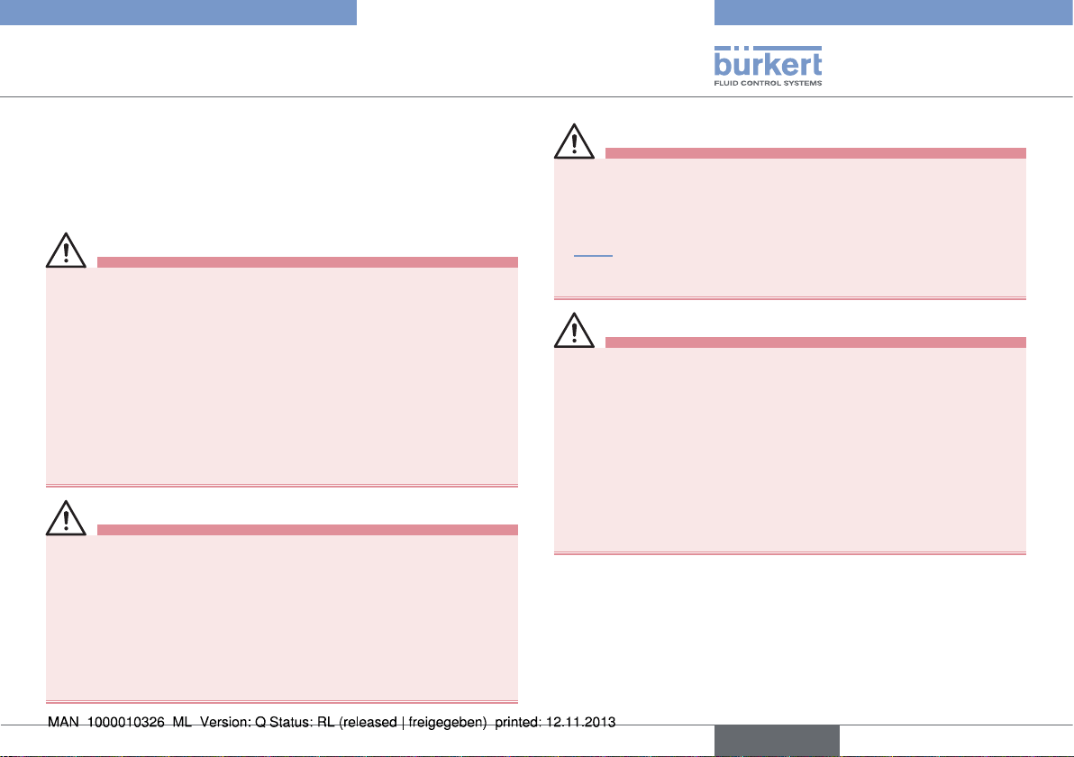
Warning
Risk of injury if the fluid pressure / temperature dependency
is not respected.
• Take into account the fluid pressure / temperature dependency
according to the materials from which the fitting is made (see
Fig. 5) and to the measuring device used (see the relevant user
manual).
• Comply with the Pressure Directive 97/23/EC.
Warning
Danger due to non-conforming commissioning.
Non-conforming commissioning may lead to injuries and damage
the fitting and its surroundings.
• Before commissioning, make sure that the staff in charge have
read and fully understood the contents of these operating
instructions.
• In particular, observe the safety recommendations and intended
use.
• The installation must only be commissioned by suitably trained
staff.
English
29
Page 30
Type S020
Installation and commissioning
P (bar)
16
15
14
13
12
PVDF
11
10
9
8
PVC + PP
7
6
5
4
3
2
1
0
-20 0 +20 +40 +60 +80 +100 +120
1)
Except DN100 for measuring devices with clamp connection
Metal
(PN16)
PVC (PN10)
PP (PN10)
1)
DN100 for measuring
devices with clamp connection
(PN10)
PVDF (PN10)
+150
T (°C)
Fig. 5: Fluid pressure / temperature dependency curves for T
fittings used on their own
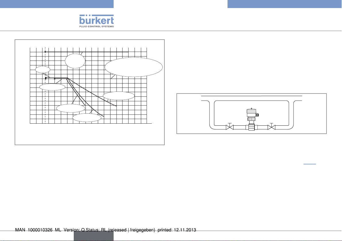
7.2. Installation onto the pipe
7.2.1. Recommandations for installing the
S020 fitting on the pipe
→ To measure the pH or the oxidation reduction potential, install
a U-shaped bypass in order to prevent the electrode drying out
and to allow calibration without stopping the process.
Fig. 6: Bypass installation of the fitting
→ For measuring the flow and depending on the design of the
pipes, respect the minimum distances in accordance with the
standard EN ISO 5167-1, from which the diagrams in Fig. 7 are
excerpted.
30
English
Page 31

Type S020
Installation and commissioning
bubbles in the pipe and the pipe filling system on the measuring
device.
50 x DN 5 x DN
With regulating valve Pipe with 2 elbows at 90° in 3
40 x DN 5 x DN
dimensions
25 x DN 5 x DN 20 x DN 5 x DN
Pipe with 2 elbows at 90° Pipe with 1 elbow at 90° or 1
T-piece
18 x DN 5 x DN 15 x DN 5 x DN
With pipe expansion With pipe reduction
Fig. 7: Upstream and downstream distances depending on the
design of the pipes.
→ To measure the flow, use a flow conditioner, if necessary, to
obtain the best accuracy.
→ For all types of measurement, respect the following additional
assembly conditions to ensure that the measuring device operates correctly (Fig. 8 and Fig. 9) and prevent the formation of air
Correct
Incorrect
Flow direction
Correct
Fig. 8: Additional recommendations on installation
Incorrect
English
31
Page 32

Type S020
Installation and commissioning
7.2.2. Installing a T fitting
Follow the recommendations on installation described in
chap. 7.2.1.
Correct
Flow direction
Flow direction
Correct
Fig. 9: Additional recommendations on installation
32
English
Incorrect
Incorrect
note
The seal on the fitting with welding end connections may be
damaged during welding.
Version for measuring devices with a G2'' nut:
• Before welding the welding ends, remove the adapter from the
fitting by unscrewing the 4 screws and remove the seal.
• After welding, correctly put the seal in the groove and the adapter
on the fitting, tighten the 4 screws, applying a nominal tightening
torque of 2 Nm.
Version for measuring devices with a clamp connection:
• Before welding the welding ends, remove the seal.
• After welding, correctly replace the seal in the groove.
→ Install the fitting by turning one of the polarising slots opposite
the flow direction.
Page 33

Type S020
Installation and commissioning
Polarizing pin for the
8045 with clamp
connection
Pipe
Polarizing slot
for the 8045
with G2" nut
Pipe
7.2.3. Installing saddles
Seal
Screws
32 mm
Nut
Pipe
Fig. 11: Installing saddles
→ Drill a hole 32 mm
in diameter in the
pipe.
→ Insert the seal pro-
vided in the saddle
groove.
→ Fix the saddle to
the pipe.
→ Insert the nuts into
their housing.
→ Insert the screws
into the nuts and
tighten them.
Fig. 10: Installing a T fitting
English
33
Page 34

Type S020
α
α
Installation and commissioning
7.2.4. Installing a welding socket with
radius, for measuring devices with a
G2'' nut
→ Drill a hole 28 mm in
diameter in the pipe.
→ Position the oblong
internal polarising
Internal polarising
slot
External polarising
slots
slot opposite the flow
direction.
→ Align 2 of the 4 external
polarizing slots (a < 3°)
in the axis of the pipe.
→ Weld around the entire
Weld
Fig. 12: Installing a welding socket with radius
circumference of the
welding socket with
radius.
7.2.5. Installing a welding socket, for
measuring devices with a clamp
connection
The welding socket can be installed:
• either on a T fitting with a short branch, installed into the pipe,
• or on the pipe which has previously been drilled and extruded to
shape a T fitting with a short branch.
→ Respect the following dimensions to drill and extrude the pipe:
DN Standard H D
32 ISO4200 38.4
40 SMS 3008 3.0 35.6
BS 4828 / ASME BPE 2.5 34.8
DIN 11850 range 2 3.0 38
ISO4200 38.4
50 SMS 3008 3.0 35.6
BS 4828 / ASME BPE 2.5 34.8
DIN 11850 range 2 3.5 38
ISO4200 38.4
65 SMS 3008 3.0 35.6
BS 4828 / ASME BPE 4.0 34.8
DIN 11850 range 2 4.0 38
ISO4200 38.4
34
English
Page 35

Type S020
Ø
D
Installation and commissioning
80 SMS 3008 4.0 35.6
BS 4828 / ASME BPE 4.5 34.8
DIN 11850 range 2 4.5 38
ISO4200 38.4
100 SMS 3008
1)
BS 4828 / ASME BPE 5.5 34.8
DIN 11850 range 2 6.5 38
±1
H
1)
Depending on the pipe, refer to line BS 4828/ASME BPE or DIN
11850 range 2 of DN100
DN L Standards
32 - ISO 4200
40 23.5 SMS 3008
BS 4825 / ASME
24.6
BPE
- DIN 11850 range 2
- ISO 4200
50 23.8 SMS 3008
BS 4825 / ASME
25.2
BPE
- DIN 11850 range 2
- ISO 4200
65 22.6 SMS 3008
BS 4825 / ASME
23.6
BPE
- DIN 11850 range 2
- ISO 4200
80 23.0 SMS 3008
BS 4825 / ASME
23.9
BPE
- DIN 11850 range 2
- ISO 4200
1)
100
SMS 3008
BS 4825 / ASME
23.0
BPE
25.1 DIN 11850 range 2
→ Make sure length L cor-
responds to the DN and
standard of the socket used,
if not the K factors given in
Table 17 are not correct.
L
English
35
Page 36

Type S020
α
α
Installation and commissioning
Marking of the flow
direction
Polarizing pin
Flow direction
→ Position the pola-
rizing pin opposite
the flow direction.
→ Align the polarizing
pin (a < 3°) in the
α
α
Polarising pin
axis of the pipe.
→ Tip 4 points at 90°
from each other.
→ Weld around the
entire circumference of the fusion
spigot.
Fig. 13: Installing a welding socket, for measuring devices with a
clamp connection
7.2.6. Installing a fusion spigot (PE, PP or
PVDF)
→ Drill a hole 40 mm in dia-
meter in the pipe.
→ Position the oblong
internal polarising slot
Internal polarising slot
External polarising slots
opposite the flow direction.
→ Align 2 of the 4 external
polarizing slots (a < 3°) in
the axis of the pipe.
→ Weld around the entire cir-
Weld
Fig. 14: Installing a fusion spigot (PE, PP or PVDF)
cumference of the fusion
spigot.
36
English
Page 37

Type S020
α
α
Installation and commissioning
7.2.7. Installing a screw-on in plastic (PP,
PVC, PE)
G 1-1/2''
ø 45
→ Drill a hole 45 mm in dia-
meter in the pipe.
→ Thread to G 1 1/2’’.
→ Screw on the spigot until it
L
G 1-1/2"
reaches length L (see Table
23) corresponding to the
DN of the pipe so that the K
factors given in Table 22 are
respected.
→ Use an appropriate sealing
material (PTFE tape, for
example).
→ When L is reached, slightly
unscrew or continue to
Internal polarising slot
External
polarising
slots
screw until 2 of the 4 polarising slots are aligned in
the axis of the pipe and the
oblong internal polarising
slot is positioned opposite
the flow direction.
DN of the screw-on
Length L to be screwed (in mm)
PVC PP / PE
100 69,3
110 57,8 -
125 57,3 57
150 57,3 57
180 61,3 61,3
200 60,8 60,8
250 - 53,6
300 - 47,5
350 - 40,7
400 - 32,9
Table 23: Lengths L to be screwed to insert flowmeters 8020, 8024,
8025, 8026, 8041 and 8045, depending on the material
of the screw-on
Fig. 15: Installing a screw-on (PP, PVC, or PE)
English
37
Page 38

7.2.8. Installing the measurement
chamber
→ Install the measurement
chamber in the main pipe or in
the bypass.
→ Pay attention to the flow
direction of the fluid.
→ Screw the G 1/2'' connections
to the pipe.
Fig. 16: Installing the measurement chamber
Type S020
Installation and commissioning
38
English
Page 39

Type S020
Installation and commissioning
7.2.9. Graph - pipe DN - fluid velocity - flow rate
The graph is used to determine the DN of the pipe and the fitting appropriate to the application, according to the fluid velocity and the flow rate.
m/s
0.01
0.1 0.3 0.5 1 3 5 10
fps
30
Fluid velocity
0.3 0.5 1 3 5 10
DN 400
DN 350
DN 300
DN 250
DN 200
DN 150
DN 125
DN 100
DN 80 (DN100)*
DN 65 (DN80)*
DN 50 (DN65)*
DN 40 (DN50)*
DN 32 (DN40)*
DN 25 (DN32)*
DN 20 (DN25)*
DN 15 (DN15 ou DN20)*
DN 08
DN 06
/h
3
m
5000
2000
1000
500
200
100
50
20
10
5
1
2
0.5
0.2
0.1
0.05
0.02
Flow rate
l/min
100000
US gpm
50000
20000
30000
10000
20000
5000
10000
2000
5000
1000
3000
2000
500
1000
200
500
100
200
50
100
20
50
10
20
10
1
2
5
0.5
0.2
0.5
0.1
0.2
0.05
English
* For the following fittings:
• external thread connections acc. to SMS 1145,
BS 4825 / ASME BPE or DIN 1850 range 2,
• with weld end connections acc. to SMS 3008,
BS 4825 / ASME BE or DIN 32676
• with clamp connections acc. to SMS 3017 / ISO 2852,
39
1
2
5
Page 40

Type S020
Maintenance
8. MAINTENANCE
8.1. Safety instructions
danger
Risk of injury due to high pressure in the installation.
• Stop the circulation of fluid, cut off the pressure and drain the
pipe before loosening the process connections.
Risk of injury due to high fluid temperatures.
• Use safety gloves to handle the fitting.
• Stop the circulation of fluid and drain the pipe before loosening
the process connections.
• Keep all easily flammable fluid or material away from the fitting.
Risk of injury due to the nature of the fluid.
• Respect the prevailing regulations on accident prevention and
safety relating to the use of aggressive fluids.
Warning
Risk of injury due to non-conforming maintenance.
• Maintenance must only be carried out by qualified and skilled
staff with the appropriate tools.
• Ensure that the restart of the installation is controlled after any
interventions.
8.2. Cleaning
note
The fitting may be damaged by the cleaning product.
• Clean the fitting with a cloth dampened with water or a detergent compatible with the materials the fitting is made of.
40
English
Page 41

Type S020
Spare parts and accessories
9. SPARE PARTS AND
ACCESSORIES
attention
Risk of injury and/or damage caused by the use of unsuitable
parts.
Incorrect accessories and unsuitable spare parts may cause
injuries and damage the fitting and the surrounding area.
• Use only original accessories and original spare parts from
Bürkert.
Accessory Order code
Certificate
Certificate 3.1 (S020 in stainless steel)
Certificate 2.2
Surface roughness certificate
Calibration certificate (S020 combined with
the flowmeter inserted)
FDA approval
440790
440789
444898
550676
449788
Spare part Order code
Adapter (with 4 screws) (Fig. 17)
in stainless steel
in PVC
in PP
in PVDF
Set of O-ring seals (DN6 to DN65) for
adapter in stainless steel
FKM (5 parts)
EPDM (5 parts)
Fig. 17: Adapter with 4 screws
555484
561175
561176
561177
428971
428972
English
41
Page 42

Type S020
Spare parts and accessories
Spare part Order code
Set of seals (DN6 to DN65) for adapter in
plastic (Fig. 18)
FKM (1 O-ring seal and 1 flat seal)
EPDM (1 O-ring seal and 1 flat seal)
561043
561044
Fig. 18: Set of seals for adapter in plastic
Spare part Order code
Plug fitted with an O-ring seal in FKM, nut
in PC and snap ring (all DNs) (Fig. 19)
in stainless steel
in PVC
in PP
438755
438754
627614
Plug
O-ring seal in FKM
Snap ring
Nut in PC
Fig. 19: Plug with O-ring seal, nut and snap ring
Spare part Order code
O-ring seal in EPDM with FDA agreement, for
730837
a T fitting or a welding socket for devices with
a clamp connection (see Fig. 20)
O-ring seal in FEP with FDA agreement, for a
730839
T fitting or a welding socket for devices with a
clamp connection (see Fig. 20)
Clamp (see Fig. 20)
Plug for T fittings or welding sockets for mae-
731164
565200
suring devices with a clamp connection (see
Fig. 20)
42
English
Page 43

Type S020
Spare parts and accessories
Plug
Clamp
O-ring seal
Fig. 20: Plug, clamp and seal for an S020 for measuring devices
with a clamp connection
Spare part Order code
Set of 2 O-ring seals for the end pieces +
1 flat seal and 1 O-ring seal for the adapter
(T fittings with true union connection only)
(Fig. 21)
FKM - DN8
FKM - DN15
FKM - DN20
FKM - DN25
448679
431555
431556
431557
Spare part Order code
FKM - DN32
FKM - DN40
FKM - DN50
EPDM - DN8
EPDM - DN15
EPDM - DN20
EPDM - DN25
EPDM - DN32
EPDM - DN40
EPDM - DN50
O-ring
seals
431558
431559
431560
448680
431561
431562
431563
431564
431565
431566
O-ring or flat seal
Fig. 21: Seals for a fitting with true union connection
English
43
Page 44

Type S020
Packaging, Transport, storage
10. PACKAGING, TRANSPORT,
STORAGE
attention
Damage due to transport
Transport may damage an insufficiently protected part.
• Transport the fitting in shock-resistant packaging and away
from humidity and dirt.
• Do not expose the fitting to temperatures that may exceed the
admissible storage temperature range.
Poor storage can damage the fitting.
• Store the fitting in a dry place away from dust.
• Storage temperature -15 to +60°C.
Damage to the environment caused by products contaminated by fluids.
• Dispose of the fitting and its packaging in an environmentallyfriendly way.
• Keep to the existing provisions on the subject of waste disposal
and environmental protection.
11. DISPOSAL OF THE FITTING
→
Dispose of the fitting and its packaging in an environmentallyfriendly way.
note
Damage to the environment caused by products contaminated by fluids.
• Keep to the existing provisions on the subject of waste disposal
and environmental protection.
note
Comply with the national and/or local regulations which
concern the area of waste disposal.
44
English
Page 45

Typ S020
Inhaltsverzeichnis
1. DIE BEDIENUNGSANLEITUNG ...............................................................5
1.1. Darstellungsmittel ..............................................................................5
2. BESTIMMUNGSGEMÄSSE VERWENDUNG ......................................6
3. GRUNDLEGENDE SICHERHEITSHINWEISE ....................................6
4. ALLGEMEINE HINWEISE .............................................................................7
4.1. Herstelleradresse und internationale Kontaktadressen 7
4.2. Gewährleistung ....................................................................................7
4.3. Informationen im Internet ...............................................................7
5. BESCHREIBUNG .............................................................................................8
5.1. Vorgesehener Einsatzbereich ......................................................8
6. TECHNISCHE DATEN ...................................................................................8
6.1. Betriebsbedingungen .......................................................................8
6.2. Verfügbare Zertifikate .......................................................................8
6.3. Allgemeine Technische Daten .....................................................9
6.3.1. Verfügbare Durchmesser .....................................................9
6.3.2. Werkstoffe ..............................................................................9
6.3.3. Abmessungen der T-Fittings ............................................10
6.3.4. Abmessungen der Stutzen ................................................17
6.3.5. Abmessungen der Anschluss-Schellen .........................19
6.3.6. Abmessungen der Messkammer .....................................19
6.4. K-Faktoren ...........................................................................................20
6.4.1. Referenzbedingungen ........................................................20
6.4.2. Berechnung der K-Faktoren (in Pulse/Liter)
der Anschluss-Schellen, Schweißstutzen oder
Einschraubstutzen ...............................................................20
6.4.3. K-Faktoren (in Pulse/Liter) der T-Fittings mit
einem Messgerät Typ 8041 oder 8045 mit
G2''-Überwurfmutter ...........................................................21
6.4.4. K-Faktoren (in Pulse/Liter) der T-Fittings und
der Schweißstutzen mit einem Messgerät 8041
oder 8045 mit Clamp-Anschluss ....................................23
6.4.5. K-Faktoren (in Pulse/Liter) der T-Fittings mit
einem Messgerät Typ 8020, 8024, 8025 oder 8026 23
6.4.6. K-Faktoren (in Pulse/Liter) der Anschluss-Schellen ...25
6.4.7. K-Faktoren (in Pulse/Liter) der Schweißstutzen
für Messgeräte mit G2''-Überwurfmutter .......................26
6.4.8. K-Faktoren (in Pulse/Liter) der Einschraubstutzen ......28
7. INSTALLATION UND INBETRIEBNAHME ........................................29
7.1. Sicherheitshinweise ....................................................................... 29
7.2. Fluidischer Anschluss ................................................................... 30
7.2.1. Empfehlungen für die Montage des Fittings
S020 in die Rohrleitung .....................................................30
7.2.2. Installation eines T-Fittings ................................................32
7.2.3. Installation der Anschluss-Schellen ................................33
deutsch
3
Page 46

7.2.4. Installation eines Schweißstutzen mit Radius,
für Messgeräte mit G2''-Überwurfmutter .......................34
7.2.5. Installation eines Schweißstutzens für Messge-
räte mit Clamp-Anschluss .................................................34
7.2.6. Installation eines Schweißstutzens aus
Kunststoff (PE, PP oder PVDF) .......................................36
7.2.7. Installation eines Einschraubstutzens aus
Kunststoff (PP, PVC, PE) ............................................................37
7.2.8. Installation der Messkammer ............................................38
7.2.9. Ermittlung der DN der Rohrleitung - Fließges-
chwindigkeit - Durchfluss ..................................................39
8. WARTUNG ........................................................................................................40
8.1. Sicherheitshinweise ....................................................................... 40
8.2. Reinigung ............................................................................................. 40
9. ERSATZTEILE UND ZUBEHÖR ............................................................. 41
10. VERPACKUNG, TRANSPORT, LAGERUNG ..................................44
11. ENTSORGUNG DES GERÄTES .......................................................... 44
deutsch
4
Page 47

Typ S020
Die Bedienungsanleitung
1. DIE BEDIENUNGSANLEITUNG
Die Bedienungsanleitung beschreibt den gesamten Lebenszyklus
des Fittings. Bewahren Sie diese Anleitung so auf, dass sie für jeden
Benutzer zugänglich ist und jedem neuen Eigentümer des Fittings
wieder zur Verfügung steht.
Diese Bedienungsanleitung enthält wichtige Informationen
zur Sicherheit!
Das Nichtbeachten dieser Hinweise kann zu gefährlichen Situationen führen.
• Diese Bedienungsanleitung muss gelesen und verstanden
werden.
1.1. Darstellungsmittel
Gefahr!
Warnt vor einer unmittelbaren Gefahr!
• Bei Nichteinhaltung sind Tod oder schwere Verletzungen die
Folge.
WarnunG!
Warnt vor einer möglicherweise gefährlichen Situation!
• Bei Nichteinhaltung drohen schwere Verletzungen oder Tod.
VOrSIChT!
Warnt vor einer möglichen Gefährdung!
• Nichtbeachtung kann mittelschwere Verletzungen oder leichte
Verletzungen zu Folge haben.
hInWeIS!
Warnt vor Sachschäden!
• Bei Nichtbeachtung kann das Fitting oder die Anlage beschädigt werden.
bezeichnet wichtige Zusatzinformationen, Tipps und
Empfehlungen.
verweist auf Informationen in dieser Bedienungsanleitung
oder in anderen Dokumentationen.
→ markiert einen Arbeitsschritt, den Sie ausführen müssen.
deutsch
5
Page 48

Typ S020
Bestimmungsgemässe Verwendung
2. BESTIMMUNGSGEMÄSSE
VERWENDUNG
Bei nicht bestimmungsgemäßem Einsatz dieses Fittings
können Gefahren für Personen, Anlagen in der Umgebung
und die Umwelt entstehen.
• Das Fitting S020 dient zur Installation eines Insertion-Gerätes in
eine Rohrleitung.
• Für den Einsatz sind die in den Vertragsdokumenten und der
Bedienungsanleitung spezifizierten zulässigen Daten, Betriebsund Einsatzbedingungen zu beachten.
• Zum sicheren und problemlosen Einsatz des Fittings müssen
Transport, Lagerung und Installation ordnungsgemäß erfolgen,
außerdem müssen Betrieb und Wartung sorgfältig durchgeführt
werden.
• Achten Sie immer darauf, dieses Fitting auf ordnungsgemäße
Weise zu verwenden.
→ Beachten Sie bei der Ausfuhr des Fittings gegebenenfalls beste-
hende Beschränkungen.
3. GRUNDLEGENDE SICHERHEITSHINWEISE
Diese Sicherheitshinweise berücksichtigen keine:
• Zufälligkeiten und Ereignisse, die bei Montage, Betrieb und Wartung
der Geräte auftreten können.
• Ortsbezogenen Sicherheitsbestimmungen, für deren Einhaltung,
auch in Bezug auf das Installations- und Wartungspersonal, der
Betreiber verantwortlich ist.
Gefahr durch hohen Druck in der Anlage!
Gefahr durch hohe Flüssigkeitstemperaturen!
Gefahr aufgrund der Art der Flüssigkeit!
Allgemeine Gefahrensituationen.
Zum Schutz vor Verletzungen ist zu beachten,
• dass die Anlage nicht unbeabsichtigt betätigt werden kann.
• Installations- und Instandhaltungsarbeiten dürfen nur von autorisiertem Fachpersonal mit geeignetem Werkzeug ausgeführt
werden.
• Nach einer Unterbrechung der elektrischen Versorgung ist ein
definierter oder kontrollierter Wiederanlauf des Prozesses zu
gewährleisten.
• Betreiben Sie das Fitting nur in einwandfreiem Zustand und
unter Beachtung der Bedienungsanleitung.
6
deutsch
Page 49

Typ S020
Allgemeine Hinweise
4. ALLGEMEINE HINWEISE
Allgemeine Gefahrensituationen (Folge).
Zum Schutz vor Verletzungen ist zu beachten,
• Bei der Einsatzplanung und dem Betrieb des Fittings die allgemeinen Regeln der Technik einhalten.
• Dieses Fitting nicht in einem explosionsgefährdeten Bereich
verwenden.
• Keine Flüssigkeit verwenden, die sich nicht mit den Werkstoffen
verträgt, aus denen das Fitting besteht.
• Dieses Fitting nicht in einer Umgebung verwenden, die mit den
Werkstoffen, aus denen es besteht, inkompatibel ist.
• Belasten Sie das Fitting nicht mechanisch (z. B. durch Ablage von
Gegenständen oder als Trittstufe).
• Nehmen Sie keine äußerlichen oder innerlichen Veränderungen
am Fitting vor.
hInWeIS!
Das Fitting kann durch die Flüssigkeit beschädigt werden.
• Kontrollieren Sie systematisch die chemische Verträglichkeit der
Werkstoffe, aus denen das Fitting besteht, und der Flüssigkeiten, die mit diesem in Berührung kommen können (zum Beispiel:
Alkohole, starke oder konzentrierte Säuren, Aldehyde, Basen,
Ester, aliphatische Verbindungen, Ketone, aromatische oder
halogenierte Kohlenwasserstoffe, Oxidations- und chlorhaltige
Mittel).
4.1. Herstelleradresse und internationale Kontaktadressen
Sie können mit dem Hersteller des Fittings unter folgender Adresse
Kontakt aufnehmen:
Bürkert SAS
Rue du Giessen
BP 21
F-67220 TRIEMBACH-AU-VAL
Die internationale Kontaktadressen finden Sie auf den letzten Seiten
dieser Bedienungsanleitung.
Außerdem im Internet unter: www.burkert.com
4.2. Gewährleistung
Voraussetzung für die Gewährleistung ist der bestimmungsgemäße Gebrauch des S020 unter Beachtung der im vorliegenden
Handbuch spezifizierten Einsatzbedingungen.
4.3. Informationen im Internet
Bedienungsanleitungen und Datenblätter zum Typ S020 finden Sie im
Internet unter: www.buerkert.de
deutsch
7
Page 50

Typ S020
Beschreibung
5. BESCHREIBUNG
5.1. Vorgesehener Einsatzbereich
Mit dem Fitting S020 können Geräte für die Messung von Durchfluss,
pH, Redoxpotential (REDOX) oder Leitfähigkeit leicht an Rohrleitungen
von DN6 bis DN400 installiert werden.
Das Fitting S020 ist in verschiedenen Ausführungen für die Installation
der Messgeräte mit G2''-Überwurfmutter oder der Messgeräte mit
Sensor mit Clamp-Anschluss verfügbar.
Die Messkammer S020 ermöglicht
• einerseits die Installation eines Sensors zur Messung von pH,
Redoxpotential oder Leitfähigkeit in einer Rohrleitung
• und garantiert andererseits, dass der Messsensor von der Flüssigkeit umspült wird.
6. TECHNISCHE DATEN
6.1. Betriebsbedingungen
Flüssigkeitstemperatur
UmgebungsTemperatur
Druckklasse
6.2. Verfügbare Zertifikate
• Zertifikat 3.1, nur S020 aus Edelstahl
• Zertifikat 2.2
• Zertifikat bezüglich Rauigkeit
• Kalibrierzertifikat
• FDA-Zulassung (mit EPDM-Dichtung), nur S020 aus Edelstahl
abhängig vom verwendeten Gerät und vom Werkstoff des Fittings S020. Siehe das Handbuch des
Gerätes und die Druck-Temperatur-Kurve der Flüssigkeit in Bild 5. Wenn die Bereiche unterschiedlich
sind, den Bereich, der am meisten einschränkt,
verwenden.
abhängig vom verwendeten Gerät. Siehe das entsprechende Handbuch.
abhängig vom verwendeten Gerät und vom Werkstoff des Fittings S020. Siehe das Handbuch
des Gerätes und die Druck-Temperatur-Kurve der
Flüssigkeit in Bild 5. Wenn die Druck-Grenzwerte
unterschiedlich sind, den geringsten Maximaldruck
nicht überschreiten.
8
deutsch
Page 51

Typ S020
Technische Daten
6.3. Allgemeine Technische Daten
6.3.1. Verfügbare Durchmesser
Die verfügbaren Durchmesser hängen von der Bauform des Fittings
S020 ab.
Siehe die Datenblätter der Fittings S020 und des verwendeten Gerätes, um den passenden DN zu ermitteln.
Tab. 1: Verfügbare Durchmesser je nach Bauform des Fittings
Bauform des S020 Verfügbare DN
T-Fittings für Messgeräte mit
G2''-Überwurfmutter
T-Fittings für Messgeräte mit
Clamp-Anschluss
Schweißstutzen mit Radius, für
Messgeräte mit G2''-Überwurfmutter
Schweißstutzen aus Kunststoff DN65 bis DN400
Einschraubstutzen
1)
Schweißstutzen für Messgeräte mit
Clamp-Anschluss
Anschluss-Schellen
1)
Nur zur Durchflussmessung.
1)
DN6 bis DN65
DN32 bis DN100
DN50 bis DN350
DN100 bis DN400
DN32 bis DN100
DN50 bis DN200
6.3.2. Werkstoffe
Tab. 2: Werkstoffe je nach Bauform des Fittings S020
Bauform des S020 Werkstoffe
Gehäuse Zwischenstutzen Dichtung
T-Fittings für
Messgeräte mit
G2''-Überwurfmutter
T-Fittings für
Messgeräte mit
Clamp-Anschluss
Schweißstutzen
mit Radius, für
Messgeräte mit
G2''-Überwurfmutter
Schweißstutzen
Schweißstutzen
für Messgeräte mit
Clamp-Anschluss
Einschraubstutzen
Anschluss-Schellen PP PVC EPDM
Edelstahl (316L - 1.4404) FKM
Messing Edelstahl (316L
- 1.4404)
oder
EPDM
PVC
PP
PVDF
Edelstahl
- -
(316L )
Edelstahl
- -
(316L
- 1.4404)
PE - PP - -
PVDF - -
Edelstahl
- -
(316L )
PVC - -
PE - PP - -
deutsch
9
Page 52

Typ S020
Technische Daten
Messkammer Edelstahl
- -
(316L
- 1.4404)
6.3.3. Abmessungen der T-Fittings
Tab. 3: Abmessungen des Fittings S020 mit G-, Rc- oder NPT-
Innengewinde-Anschlüssen aus Edelstahl oder Messing,
für Messgeräte mit G2''-Überwurfmutter
DN [mm] P [mm] A [mm] D [Zoll] L [mm]
15 80.3 84.0 G 1/2
NPT 1/2
Rc 1/2
20 77.8 94.0 G 3/4
NPT 3/4
Rc 3/4
25 78.0 104.0 G 1
NPT 1
Rc 1
32 81.6 119.0 G 1 1/4
NPT 1 1/4
Rc 1 1/4
40 85.4 129.0 G 1 1/2
NPT 1 1/2
Rc 1 1/2
50 91.5 148.5 G 2
NPT 2
Rc 2
16.0
17.0
15.0
17.0
18.3
16.3
23.5
18.0
18.0
23.5
21.0
21.0
23.5
20.0
19.0
27.5
24.0
24.0
P
D
L
A
10
deutsch
Page 53

Typ S020
Technische Daten
Tab. 4: Abmessungen des Fittings S020 mit G Außengewinde-
Anschlüssen aus Edelstahl, Messing (DN15 bis 50) oder PVC
(nur DN6 und 8), für Messgeräte mit G2''-Überwurfmutter
DN
[mm]
6 75.3 90.0 G 1/2 14.0
8 75.3 90.0 G 1/2 14.0
15 80.3 84.0 G 3/4 11.5
20 77.8 94.0 G 1 13.5
25 78.0 104.0 G 1 1/4 14.0
32 81.6 119.0 G 1 1/2 18.0
40 85.4 129.0 M55 x 2 19.0
50 91.5 148.5 M64 x 2 20.0
P
[mm]
A
[mm]
D
[Zoll]
L
[mm]
P
D
L
A
Tab. 5: Abmessungen des Fittings S020 mit Außengewinde-
Anschlüssen nach SMS1145 aus Edelstahl, für
Messgeräte mit G2''-Überwurfmutter
DN
[mm]P[mm]
25 77.8 130 Rd40 x 1/6"
40 81.6 164 Rd60 x 1/6"
50 85.4 173 Rd70 x 1/6"
A
[mm]
D
[Zoll]
P
D
A
deutsch
11
Page 54

Tab. 6: Abmessungen des Fittings S020 mit Schweißstutzen-
Anschlüssen nach EN ISO 1127 / ISO 4200, SMS 3008
oder BS 4825/ASME BPE aus Edelstahl, für Messgeräte
mit G2''-Überwurfmutter
DN
[mm]P[mm]A[mm]
15 80.3
-
-
20 77.8
-
83.3
25 78.0
77.8
77.8
32 81.6
-
78.0
40 85.4
81.6
81.6
50 91.5
85.4
85.4
65 -
91.5
91.5
84.0
-
-
94.0
-
84.0
104.0
94.0
94.0
119.0
-
104.0
129.0
119.0
119.0
148.5
128.0
128.0
-
147.0
147.0
Norm D
EN ISO 1127 / ISO 4200
SMS 3008
ASME BPE
EN ISO 1127 / ISO 4200
SMS 3008
ASME BPE
EN ISO 1127 / ISO 4200
SMS 3008
BS 4825 / ASME BPE
EN ISO 1127 / ISO 4200
SMS 3008
BS 4825 / ASME BPE
EN ISO 1127 / ISO 4200
SMS 3008
BS 4825 / ASME BPE
EN ISO 1127 / ISO 4200
SMS 3008
BS 4825 / ASME BPE
EN ISO 1127 / ISO 4200
SMS 3008
BS 4825 / ASME BPE
[mm]s[mm]
21.30
-
-
26.90
-
19.05
33.70
25.00
25.40
42.40
-
32.00
48.30
38.00
38.10
60.30
51.00
50.80
-
63.50
63.50
1.60
-
-
1.60
-
1.65
2.00
1.20
1.65
2.00
-
1.65
2.00
1.20
1.65
2.60
1.20
1.65
-
1.60
1.65
Typ S020
Technische Daten
s
H
�A
P
12
deutsch
Page 55

Typ S020
Technische Daten
Tab. 7: Abmessungen des Fittings S020 mit Clamp-Anschlüssen nach ISO (für Rohrleitungen nach EN ISO 1127 / ISO 4200),
SMS 3017/ISO 2852
DN [mm]
15 80.3
20 77.8
25 78.0
32 81.6
40 85.4
50 91.5
65 -
1)
Verfügbar mit Innenrauigkeit Ra = 0,8 μm
P [mm] A [mm] Norm D2 [mm] D1 [mm] D [mm]
130.0
-
-
-
-
150.0
-
80.3
-
119.0
160.0
77.8
77.8
129.0
129.0
180.0
-
-
-
-
200.0
81.6
81.6
161.0
161.0
230.0
85.4
85.4
192.0
192.0
-
91.5
91.5
216.0
216.0
1)
oder BS 4825/ASME BPE 1), aus Edelstahl, für Messgeräte mit G2''-Überwurfmutter
ISO (Rohrleitung EN ISO 1127 / ISO 4200)
SMS 3017 / ISO 2852
ASME BPE
ISO (Rohrleitung EN ISO 1127 / ISO 4200)
SMS 3017 / ISO 2852
ASME BPE
ISO (Rohrleitung EN ISO 1127 / ISO 4200)
SMS 3017 / ISO 2852
BS 4825 / ASME BPE
ISO (Rohrleitung EN ISO 1127 / ISO 4200)
SMS 3017 / ISO 2852
BS 4825 / ASME BPE
ISO (Rohrleitung EN ISO 1127 / ISO 4200)
SMS 3017 / ISO 2852
BS 4825 / ASME BPE
ISO (Rohrleitung EN ISO 1127 / ISO 4200)
SMS 3017 / ISO 2852
BS 4825 / ASME BPE
ISO (Rohrleitung EN ISO 1127 / ISO 4200)
SMS 3017 / ISO 2852
BS 4825 / ASME BPE
18.10
-
-
23.70
-
15.75
29.70
22.60
22.10
38.4
-
-
44.3
35.6
34.8
55.1
48.6
47.5
-
60.3
60.2
27.5
-
-
43.5
-
19.6
43.5
43.5
43.5
43.5
-
-
56.5
43.5
43.5
70.5
56.5
56.5
-
70.5
70.5
34.0
-
-
50.5
-
25.0
50.5
50.5
50.5
50.5
-
-
64.0
50.5
50.5
77.5
64.0
64.0
-
77.5
77.5
D
D1
D2
P
A
deutsch
13
Page 56

Typ S020
Technische Daten
Tab. 8: Abmessungen des Fittings S020 mit Flansch-Anschlüssen nach EN1092-1 (ISO PN16), ANSI B16-5-1988 und JIS 10K, aus
Edelstahl, für Messgeräte mit G2''-Überwurfmutter
DN
[mm]P[mm]A[mm]
15 80.3
80.3
80.3
20 77.8
77.8
77.8
25 78.0
78.0
78.0
32 81.6
81.6
81.6
40 85.4
85.4
85.4
50 91.5
91.5
91.5
130.0
130.0
152.0
150.0
150.0
178.0
160.0
160.0
216.0
180.0
180.0
229.0
200.0
200.0
241.0
230.0
230.0
267.0
Norm L
DIN
ANSI
JIS
DIN
ANSI
JIS
DIN
ANSI
JIS
DIN
ANSI
JIS
DIN
ANSI
JIS
DIN
ANSI
JIS
[mm]Z[mm]D2[mm]D1[mm]D[mm]
23.5
23.5
23.5
28.5
28.5
28.5
28.5
28.5
28.5
31.0
31.0
31.0
36.0
36.0
36.0
41.0
41.0
41.0
4x14.0
4x15.8
4x15.0
4x14.0
4x15.8
4x15.0
4x14.0
4x15.8
4x19.0
4x18.0
4x15.8
4x19.0
4x18.0
4x15.8
4x19.0
4x18.0
4x19.0
4x19.0
45.0
34.9
51.0
58.0
42.9
56.0
68.0
50.8
67.0
78.0
63.5
76.0
88.0
73.0
81.0
102.0
92.1
96.0
65.0
60.3
70.0
75.0
69.8
75.0
85.0
79.4
90.0
100.0
88.9
100.0
110.0
98.4
105.0
125.0
120.6
120.0
95.0
89.0
95.0
105.0
99.0
100.0
115.0
108.0
125.0
140.0
117.0
135.0
150.0
127.0
140.0
165.0
152.0
155.0
P
A
L
D2
Z
D1
D
14
deutsch
Page 57

Typ S020
A
Technische Daten
Tab. 9: Abmessungen des Fittings S020 mit Muffen- und Überwurfmutter-Anschlüssen nach DIN 8063, ASTM D 1785/76 oder JIS K aus
PVC, nach DIN 16962 aus PP oder nach ISO 10931 aus PVDF, für Messgeräte mit G2''-Überwurfmutter
DN
[mm]P[mm]D[mm]ADIN/ISO ASTM JISD1DIN/ISO ASTM JIS
15
15
20
20
25
25
1)
1)
1)
80.4
81.44374
77.8
81.45374
78.0
81.46074
128
148
144
154
160
160
130.0-129
-
145.6-145
-
161.4-161
-
20
20
25
25
32
32
21.3-18.40-90
26.7-26.45-100
33.4-32.55-110
A2
[mm]A1[mm]
11096116
106
110
116
116
110
116
D
D1
A2
A1
32 81.4 74 168 170.0 169 40 42.2 38.60 110 116
40 85.2 83 188 190.2 190 50 48.3 48.70 120 127
50 91.5 103 212 213.6 213 63 60.3 60.80 130 136
1)
Spezifisches Fitting für Analysesensoren
P
Tab. 10: Abmessungen des Fittings S020 mit Stutzen-Anschlüssen nach DIN 8063 aus PVC, nach DIN 16962 aus PP oder nach
ISO 10931 aus PVDF, für Messgeräte mit G2''-Überwurfmutter
DN
[mm]
P
[mm]
H
[mm]
A [mm]
DIN 8063 DIN 16962
ISO 10931
D [mm] L [mm]
DIN 8063 DIN 16962
ISO 10931
15 80.4 17.5 90 85 20 16.5 14
20 77.8 17.5 100 92 25 20 16
25 78.0 21.5 110 95 32 23 18
D
32 81.4 27.5 110 100 40 27.5 20
40 85.2 31.5 120 106 50 30 23
50 91.5 39.5 130 110 63 37 27
L
A
PH
deutsch
15
Page 58

Typ S020
P
Technische Daten
Tab. 11: Abmessungen des Fittings S020 mit Schweißstutzen-Anschlüssen nach EN ISO 1127 / ISO 4200, SMS 3008, BS 4825/
ASME BPE, oder DIN 11850 Reihe 2, für Messgeräte mit Clamp-Anschluss
DN [mm] P [mm] A [mm] Norm D [mm] S [mm]
32 - 130 EN ISO 1127 / ISO 4200 42.4 2
40 - 130 EN ISO 1127 / ISO 4200 48.3 2
42.5 110 SMS 3008 38 1.2
43.7 120.6 BS 4825 / ASME BPE 38.1 1.65
- 120 DIN 11850 Reihe 2 41 1.5
50 - 180 EN ISO 1127 / ISO 4200 60.3 2
49.3 164 SMS 3008 51 1.2
50.6 146 BS 4825 / ASME BPE 50.8 1.65
- 160 DIN 11850 Reihe 2 53 1.5
65 - 220 EN ISO 1127 / ISO 4200 76.1 2
54.4 210 SMS 3008 63.5 1.5
55.4 158.8 BS 4825 / ASME BPE 63.5 1.65
- 210 DIN 11850 Reihe 2 70 2
A
80 - 260 EN ISO 1127 / ISO 4200 88.9 2.3
60.7 220 SMS 3008 76.1 1.6
62 171.5 BS 4825 / ASME BPE 76.2 1.65
- 260 DIN 11850 Reihe 2 85 2
100 73.8
77.1
209.6 BS 4825 / ASME BPE 101.6 2.11
310 DIN 11850 Reihe 2 104 2
S
D
16
deutsch
Page 59

Typ S020
Technische Daten
6.3.4. Abmessungen der Stutzen
ø 49
ø 45
ø27.6
G1-1/2"
Bild 1: Abmessungen der Einschraubstutzen DN65 bis DN400 aus PVC,
PE oder PP (in mm), für Messgeräte mit G2''-Überwurfmutter
Tab. 12: Abmessungen der Edelstahl-Schweißstutzen mit Radius,
für Messgeräte mit G2"-Überwurfmutter
DN
[mm]A[mm]B[mm]R[mm]
50 56.6 61.6 30.2
65 54.5 58.6 36.7
80 53.1 56.4 44.5
100 50.7 53.2 57.2
125 48.2 50.3 70.7
150 45.7 47.4 84.2
200 41.0 42.3 109.6
250 73.6 74.7 136.6
300 67.8 68.7 162.0
350 63.9 64.7 177.8
11.5
73
93
90°
B
45
A +0.1
R4 (4x)
3
16.2
R0.5
R
Tab. 13: Abmessungen der Schweißstutzen, aus PE, PP oder
PVDF, für Messgeräte mit G2"-Überwurfmutter
DN
[mm]H[mm]PEH1
[mm]
H2
[mm]
PP
H1
[mm]
H2
[mm]
PVDF
H1
[mm]
H2
[mm]
65 72.5 13 - 13 - 10.4 80 72.5 15.6 - 15.6 - 12.5 100 72.5 19 5 19 5 15.2 6
125 102 24.2 8 - - - 150 102 27.7 10 27.7 10 - 200 102 38.9 16 38.9 16 - 250 102 48.4 21 48.4 21 - 300 102 54.5 24 54.5 24 - 350 102 61.3 28 61.3 28 - 400 102 69.1 31.5 - - - -
H
H1
H2
ø39
deutsch
17
Page 60

Typ S020
H
Ø
50,5
H
Technische Daten
Tab. 14: Abmessungen der Schweißstutzen nach EN ISO 1127 / ISO 4200, SMS 3008, BS 4825/ASME BPE, oder DIN 11850 Reihe 2,
für Messgeräte mit Clamp-Anschluss
DN [mm] H [mm] Norm
32 - ISO 4200
40 21.7 SMS 3008
1
23.7 BS 4825 / ASME BPE
- DIN 11850 Reihe 2
- ISO 4200
50 21.7 SMS 3008
23.7 BS 4825 / ASME BPE
- DIN 11850 Reihe 2
Schweißstutzen nach SMS 3008, DIN 11850 reihe 2 oder ISO 4002
- ISO 4200
65 19.7 SMS 3008
19.7 BS 4825 / ASME BPE
- DIN 11850 Reihe 2
- ISO 4200
1
Ø 50.5
80 19.7 SMS 3008
19.7 BS 4825 / ASME BPE
- DIN 11850 Reihe 2
- ISO 4200
100 19.7 SMS 3008
19.7 BS 4825 / ASME BPE
19.7 DIN 11850 Reihe 2
Schweißstutzen nach BS 4825/ASME BPE
18
deutsch
Page 61

Typ S020
Technische Daten
6.3.5. Abmessungen der
Anschluss-Schellen
Tab. 15: Abmessungen der Anschluss-Schellen aus PP/PVC
DN
[mm]D[mm]P[mm]D1[mm]H[mm]
50 116 116.0 63 155.0
65 129 115.0 75 160.0
80 144 119.0 90 171.0
100 166 124.0 110 187.0
110 181 120.0 125 191.0
125 196 127.0 140 205.0
150 216 137.0 160 225.0
180 266 161.0 200 271.0
200 290 173.0 225 297.0
D1
D
6.3.6. Abmessungen der Messkammer
ø 60.3
41
ø 33.6
P
H
62.6
17.6
ø 27
G 1/2
118
2.70
ø 60
G 1/2
Bild 2: Abmessungen der Messkammer (in mm)
80.2
19
deutsch
Page 62

Typ S020
Technische Daten
6.4. K-Faktoren
6.4.1. Referenzbedingungen
Die K-Faktoren wurden alle unter den folgenden Referenzbedingungen bestimmt: Flüssigkeit = Wasser, Wasser- und Umgebungstemperatur von 20 °C, Berücksichtigung der Mindestein- und -auslaufstrecken, angepasste Rohrleitungsabmessungen.
6.4.2. Berechnung der K-Faktoren
(in Pulse/Liter) der AnschlussSchellen, Schweißstutzen oder
Einschraubstutzen
Diese Berechnung gilt nicht für T-Fittings weder für Edelstahl-Schweißstutzen für Messgeräte mit Clamp-Anschluss.
Außer den oben erwähnten Referenzbedingungen wurden die
K-Faktoren der Anschluss-Schellen, Edelstahl-Schweißstutzen mit
Radius, Schweißstutzen und Einschraubstutzen mittels den in den
Tabellen angegebenen Rohrleitungs-Außendurchmessern (D
und -Wandungsdicken (s
Werkstoff
) bestimmt.
Werkstoff
→ Falls die Abmessungen der verwendeten Rohrleitung leicht
von den in den Tabellen angegebenen Abmessungen D bzw.
s abweichen, muss der K-Faktor gemäß einer der folgenden
Formeln neu berechnet werden:
Diese Formeln können nur bei Rohrleitungen verwendet
werden, deren Durchmesser nicht mehr als +/- 5% von den
angegebenen theoretischen Werten abweicht.
2
d
Kn = Kt x
t
2
d
n
Bild 3: Bei Verwendung des Fittings mit einem Flügelrad-Durchflusssensor
2
d
Kn = Kt x
n
2
d
t
Bild 4: Bei Verwendung des Fittings mit einem elektromagne-
tischen Durchflusssensor
Kn = neu berechneter K-Faktor
= in der Tabelle angegebener K-Faktor
K
d
t
= D
t
Werkstoff
- 2s
= theoretischer Innendurchmesser der
Werkstoff
Rohrleitung, berechnet anhand der in
)
den Tabellen für jeden Fitting-Werkstoff
angegebenen Werte D
s
(D
Werkstoff
der Rohrleitung und s
Werkstoff
dungsdicke der Rohrleitung)
= Innendurchmesser der verwendeten Rohrleitung
d
n
Werkstoff
= Außendurchmesser
Werkstoff
und
= Wan-
20
deutsch
Page 63

Typ S020
Technische Daten
6.4.3. K-Faktoren (in Pulse/Liter) der T-Fittings mit einem Messgerät Typ 8041 oder 8045
mit G2''-Überwurfmutter
Wir raten davon ab, ein Messgerät des Typs 8041 oder 8045 in einem Fitting S020 aus Messing zu verwenden, da hierbei Messabweichungen auftreten können.
Wenn das Messgerät die K-Faktoren nicht automatisch umrechnet, die Umrechnung mit einer der folgenden Formeln durchführen:
• K-Faktor in Pulse/US-Gallone = K-Faktor in Pulse/Liter x 3,785 zur Umrechnung des Durchflusses in US-Gallonen/Zeiteinheit
• K-Faktor in Pulse/UK-Gallone = K-Faktor in Pulse/Liter x 4,546 zur Umrechnung des Durchflusses in UK-Gallonen/Zeiteinheit
Jeweils zwei Versionen der Fittings S020 mit DN15 und DN20 mit verschiedenen K-Faktoren sind vorhanden.
Nur die Version 2 mit der Markierung "v2" ist ab März 2012 verfügbar. Die Markierung "v2" befindet sich
• auf der Unterseite eines DN15 aus Kunststoff:
V2
• auf der Seite eines DN15 oder DN20 aus Metall:
V2
deutsch
21
Page 64

Typ S020
Technische Daten
Tab. 16: K-Faktoren in Abhängigkeit des Anschlusstyps, der Anschluss-Norm und der Werkstoffe der T-Fittings mit einem Messgerät 8041
oder 8045 mit G2"-Überwurfmutter
Werkstoff Typ der Anschlüsse und Norm
Edelstahl Schweißstutzen
• nach SMS 3008 - - - - - - 1,98 - 4,32 6,68 11,3
• nach BS 4825 / ASME BPE - - - - 1,69 1,75 1,98 2,85 4,32 6,68 11,3
• nach EN ISO 1127 / ISO 4200 - - 1,69 1,75 1,98 - 2,85 4,32 6,68 11,3 -
Edelstahl Außengewinde
• nach SMS 1145 - - - - - - 1,98 - 4,32 6,68 -
• G 0,355 0,530 1,69 1,75 1,98 - 2,85 4,32 6,68 11,3 -
Edelstahl Innengewinde
• G, Rc, NPT 0,355 0,530 1,69 1,75 1,98 - 2,85 4,32 6,68 11,3 -
Edelstahl Clamp
• nach SMS 3017 / ISO 2852 - - - - - - 1,98 - 4,32 6,68 11,3
• nach BS 4825 / ASME BPE - - - - 1,69 1,75 1,98 - 4,32 6,68 11,3
• nach ISO (für Rohrleitungen nach
EN ISO 1127 / ISO 4200)
Edelstahl Flansch
• nach EN1092-1 (ISO PN16)
• nach ANSI B16-5-1998
• nach JIS 10K
Messing Alle - - - - 1,98 - 2,85 4,32 6,68 11,3 PVC Alle 0,310 0,470 1,33 1,33 1,45 - 2,26 4,29 7,30 12,5 PP Alle - - 1,29 1,37 1,44 - 2,21 4,30 7,16 12,2 PVDF Alle - - 1,21 1,22 1,37 - 2,04 4,03 6,88 11,5 -
K-Faktor [Pulse/Liter]
DN6 DN8 DN15 DN15 v2 DN20 DN20 v2 DN25 DN32 DN40 DN50 DN65
- - 1,69 1,75 1,98 - 2,85 4,32 6,68 11,3 -
- - 1,69 1,75 1,98 - 2,85 4,32 6,68 11,3 -
22
deutsch
Page 65

Typ S020
Technische Daten
6.4.4. K-Faktoren (in Pulse/Liter) der
T-Fittings und der Schweißstutzen
mit einem Messgerät 8041 oder
8045 mit Clamp-Anschluss
Tab. 17: K-Faktoren der T-Fittings mit einem Messgerät mit
Clamp-Anschluss
Typ der
Anschlüsse und
Norm
nach SMS 3008 5.23 10.4 15.9 24.7 nach BS 4825 /
ASME BPE
nach DIN 11850
Reihe 2
nach ISO 4200 - - - - -
DN40 DN50 DN65 DN80 DN100
5.33 10.4 16.7 25.7 50.3
- - - - 52.7
6.4.5. K-Faktoren (in Pulse/Liter) der
T-Fittings mit einem Messgerät Typ
8020, 8024, 8025 oder 8026
Wenn das Messgerät die K-Faktoren nicht automatisch umrechnet,
die Umrechnung mit einer der folgenden Formeln durchführen:
• K-Faktor in Pulse/US-Gallone = K-Faktor in Pulse/Liter x 3,785
zur Umrechnung des Durchflusses in US-Gallonen/Zeiteinheit
• K-Faktor in Pulse/UK-Gallone = K-Faktor in Pulse/Liter x 4,546
zur Umrechnung des Durchflusses in UK-Gallonen/Zeiteinheit
Jeweils zwei Versionen der Fittings S020 mit DN15 und
DN20 mit verschiedenen K-Faktoren sind vorhanden.
Nur die Version 2 mit der Markierung "v2" ist ab März 2012
verfügbar. Die Markierung "v2" befindet sich
• auf der Unterseite eines DN15 aus Kunststoff:
V2
• auf der Seite eines DN15 oder DN20 aus Metall:
V2
Kein Fitting S020 mit DN6, DN8, DN15, DN15 Version 2
(V2) oder DN20 Version 2 (V2) mit den Flügelrad-Durchflussmessgeräten 8020, 8024, 8025, 8026 verwenden.
deutsch
23
Page 66

Typ S020
Technische Daten
Tab. 18: K-Faktoren in Abhängigkeit des Anschlusstyps, der Anschluss-Norm und der Werkstoffe der T-Fittings mit einem Messgerät 8020,
8024, 8025 oder 8026
Werkstoff Typ der Anschlüsse und Norm
Edelstahl Schweißstutzen
• nach SMS 3008 - - - - - - 64,0 - 30,9 19,5 11,2
• nach BS 4825 / ASME BPE - - - - - - 64,0 48,3 30,9 19,5 11,2
• nach EN ISO 1127 / ISO 4200 - - - - 64,0 - 48,3 30,9 19,5 11,2 -
Edelstahl Außengewinde
• nach SMS 1145 - - - - - - 64,0 - 30,9 19,5 -
• G - - - - 64,0 - 48,3 30,9 19,5 11,2 -
Edelstahl Innengewinde
• G, Rc, NPT - - - - 64,0 - 48,3 30,9 19,5 11,2 -
Edelstahl Clamp
• nach SMS 3017 / ISO 2852 - - - - - - 64,0 - 30,9 19,5 11,2
• nach BS 4825 / ASME BPE - - - - - - 64,0 - 30,9 19,5 11,2
• nach ISO (für Rohrleitungen
nach EN ISO 1127 / ISO 4200)
Edelstahl Flansch
• nach EN1092-1 (ISO PN16) - - - - 64,0 - 48,3 30,9 19,5 11,2 -
• nach ANSI B16-5-1998
• nach JIS 10K
Messing Alle - - - - 64,0 - 48,3 30,9 19,5 11,2 PVC Alle - - - - 81,1 - 56,6 29,9 18,6 10,7 PP Alle - - - - 75,1 - 53,6 29,0 17,4 10,3 PVDF Alle - - - - 81,2 - 60,3 31,9 19,4 11,1 -
K-Faktor [Pulse/Liter]
DN6 DN8 DN15 DN15 v2 DN20 DN20 v2 DN25 DN32 DN40 DN50 DN65
- - - - 64,0 - 48,3 30,9 19,5 11,2 -
- - - - 64,0 - 48,3 30,9 19,5 11,2
24
deutsch
Page 67

Typ S020
Technische Daten
6.4.6. K-Faktoren (in Pulse/Liter) der Anschluss-Schellen
Falls die Abmessungen der verwendeten Rohrleitung leicht von den in der Tabelle angegebenen Abmessungen D bzw. s abweichen,
muss der K-Faktor mit einer der Formeln in Kap. 6.4.2 neu berechnet werden.
Wenn das Messgerät die K-Faktoren nicht automatisch umrechnet, die Umrechnung mit einer der folgenden Formeln durchführen:
• K-Faktor in Pulse/US-Gallone = K-Faktor in Pulse/Liter x 3,785 zur Umrechnung des Durchflusses in US-Gallonen/Zeiteinheit
• K-Faktor in Pulse/UK-Gallone = K-Faktor in Pulse/Liter x 4,546 zur Umrechnung des Durchflusses in UK-Gallonen/Zeiteinheit
Tab. 19: K-Faktoren, Außendurchmesser und theoretische Querschnitte der Fittings mit Anschlussschelle
Messgerätetyp 8020, 8024, 8025, 8026 8041, 8045 Außendurchmesser und theoretische Querschnitte
Rohrleitungswerkstoff
DN
50 14,2 (L) 15,6 (L) 10,4 (L) 9,28 (L) 63 4,7 63 5,8
65 11,2 (L) 12,3 (L) 14,5 (L) 12,9 (L) 75 5,5 75 6,9
80 7,37 (L) 7,80 (L) 21,3 (L) 20,4 (L) 90 6,6 90 8,2
100 4,83 (L) 5,29 (L) 33,0 (L) 30,4 (L) 110 8,1 110 10
110 3,45 (L) - 44,7 (L) - 125 9,2 - 125 2,55 (L) 3,10 (L) 63,7 (L) 52,1 (L) 140 10,3 140 12,8
150 1,67 (L) 2,03 (L) 137 (L) 78,8 (L) 160 6,2 160 14,6
180 1,08 (L) 1,37 (L) 197 (L) 116 (L) 200 9,6 200 18,2
200 0,80 (L) 1,07 (L) 290 (L) 147 (L) 225 8,6 225 20,5
(L): Langversion des Sensors
PVC PE / PP PVC PE / PP
D
PVC
[mm]
s
PVC
[mm]
D
PP
[mm]
s
PP
[mm]
deutsch
25
Page 68

Typ S020
Technische Daten
6.4.7. K-Faktoren (in Pulse/Liter) der Schweißstutzen für Messgeräte mit
G2''-Überwurfmutter
Falls die Abmessungen der verwendeten Rohrleitung leicht von den in der Tabelle angegebenen Abmessungen D bzw. s abweichen,
muss der K-Faktor mit einer der Formeln in Kap. 6.4.2 neu berechnet werden.
Wenn das Messgerät die K-Faktoren nicht automatisch umrechnet, die Umrechnung mit einer der folgenden Formeln durchführen:
• K-Faktor in Pulse/US-Gallone = K-Faktor in Pulse/Liter x 3,785 zur Umrechnung des Durchflusses in US-Gallonen/Zeiteinheit
• K-Faktor in Pulse/UK-Gallone = K-Faktor in Pulse/Liter x 4,546 zur Umrechnung des Durchflusses in UK-Gallonen/Zeiteinheit
Tab. 20: K-Faktoren, Außendurchmesser und theoretische Querschnitte der Edelstahl-Schweißstutzen mit Radius für Messgeräte mit G2''-
Überwurfmutter, und der Schweißstutzen aus Kunststoff, mit einem 8020, 8024, 8025 oder 8026
Messgerätetyp 8020, 8024, 8025, 8026 Außendurchmesser und theoretische Querschnitte
Rohrleitungswerkstoff
DN
50 13,0 (C) - - 60,3 2,0 - - - 65 7,86 (C) 8,32 (C) 5,53 (C) 76,1 2,9 75 6,9 75 2,5
80 5,52 (C) 5,49 (C) 3,65 (C) 88,9 3,2 90 8,2 90 2,8
100 3,20 (C) 3,51 (C) 2,34 (C) 114,3 3,6 110 10 110 3,5
110 - - - - - - - - 125 2,00 (C) 2,66 (L) - 139,7 4 140 12,8 - 150 1,32 (C) 2,12 (L) - 168,3 4,5 160 14,6 - 180 - - - - - 200 18,2 - 200 0,72 (C) 0,98 (L) - 219,1 6,3 225 20,5 - 250 0,50 (L) 0,63 (L) - 273 7,7 280 25,5 - 300 0,35 (L) 0,42 (L) - 323,9 9,5 315 28,7 - -
350 0,26 (L) 0,30 (L) - 355,6 10,1 355 32,3 - 400 - 0,23 (L) - - - 400 36,4 - -
Edelstahl PE / PP PVDF
D
Stahl
[mm]
s
Stahl
[mm]
D
PE/PP
[mm]
s
PE/PP
[mm]
D
PVDF
[mm]
s
PVDF
[mm]
26
deutsch
Page 69

Typ S020
Technische Daten
Tab. 21: K-Faktoren, Außendurchmesser und theoretische Querschnitte der Schweißstutzen mit Radius und der Schweißstutzen aus
Kunststoff für 8041 oder 8045 Messgeräte mit G2''-Überwurfmutter
Messgerätetyp 8041, 8045 mit Edelstahlsensor 8041, 8045 mit PVDF-Sensor
Rohrleitungs-
werkstoff
Edelstahl PE / PP PVDF Edelstahl PE / PP PVDF
DN
Außendurchmesser und theoretische
Querschnitte
D
Stahl
[mm]
s
[mm]
Stahl
D
PE/PP
[mm]
s
PE/PP
[mm]
50 11,6 (C) - - 13,8 (C) - - 60,3 2,0 - - - -
65 20,0 (C) 17,8 (C) 24,1 (C) 24,0 (C) 21,3 (C) 28,9 (C) 76,1 2,9 75 6,9 75 2,5
80 28,5 (C) 25,6 (C) 40,8 (C) 33,2 (C) 30,7 (C) 48,9 (C) 88,9 3,2 90 8,2 90 2,8
100 49,2 (C) 38,1 (C) 70,5 (C) 60,5 (C) 45,7 (C) 84,5 (C) 114,3 3,6 110 10 110 3,5
110 - - - - - - - - - - - 125 78,0 (C) 81,7 (L) - 93,6 (C) 81,7 (L) - 139,7 4 140 12,8 - 150 98,4 (C) 103 (L) - 118 (C) 103 (L) - 168,3 4,5 160 14,6 - 180 - - - - - - - - 200 18,2 - 200 210 (C) 224 (L) - 252 (C) 224 (L) - 219,1 6,3 225 20,5 - 250 311 (L) 347 (L) - 311 (L) 347 (L) - 273 7,7 280 25,5 - 300 447 (L) 510 (L) - 447 (L) 510 (L) - 323,9 9,5 315 28,7 - 350 609 (L) 705 (L) - 609 (L) 705 (L) - 355,6 10,1 355 32,3 - 400 - 931 (L) - - 931 (L) - - - 400 36,4 - -
(C): Kurzversion des Sensors
(L): Langversion des Sensors
D
PVDF
[mm]
s
PVDF
[mm]
deutsch
27
Page 70

Typ S020
Technische Daten
6.4.8. K-Faktoren (in Pulse/Liter) der Einschraubstutzen
Falls die Abmessungen der verwendeten Rohrleitung leicht von den in der Tabelle angegebenen Abmessungen D bzw. s abweichen,
muss der K-Faktor mit einer der Formeln in Kap. 6.4.2 neu berechnet werden.
Wenn das Messgerät die K-Faktoren nicht automatisch umrechnet, die Umrechnung mit einer der folgenden Formeln durchführen:
• K-Faktor in Pulse/US-Gallone = K-Faktor in Pulse/Liter x 3,785 zur Umrechnung des Durchflusses in US-Gallonen/Zeiteinheit
• K-Faktor in Pulse/UK-Gallone = K-Faktor in Pulse/Liter x 4,546 zur Umrechnung des Durchflusses in UK-Gallonen/Zeiteinheit
Tab. 22: K-Faktoren, Außendurchmesser und theoretische Querschnitte der Einschraubstutzen
Messgerätetyp 8020, 8024, 8025, 8026 8041, 8045
Rohrleitungswerkstoff
DN
100 4,83 (L) 5,29 (L) 33,0 (L) 30,4 (L) 110 8,1 110 10
110 3,45 (L) - 44,7 (L) - 125 9,2 125 11,4
125 2,55 (L) 3,10 (L) 63,7 (L) 52,1 (L) 140 10,3 140 12,8
150 1,67 (L) 2,12 (L) 137 (L) 78,8 (L) 160 6,2 160 14,6
180 1,08 (L) 1,37 (L) 197 (L) 116 (L) 200 9,6 200 18,2
200 0,80 (L) 1,07 (L) 290 (L) 147 (L) 225 8,6 225 20,5
250 - 0,63 (L) - 347 (L) - - 280 25,5
300 - 0,42 (L) - 510 (L) - - 315 28,7
350 - 0,30 (L) - 705 (L) - - 355 32,3
400 - 0,23 (L) - 931 (L) - - 400 36,4
(L): Langversion des Sensors
28
PVC PP / PE PVC PP / PE
deutsch
Außendurchmesser und theoretische
Querschnitte
D
PVC
[mm]
s
PVC
[mm]
D
PE/PP
[mm]
s
PE/PP
[mm]
Page 71

Typ S020
Installation und Inbetriebnahme
7. INSTALLATION UND
INBETRIEBNAHME
7.1. Sicherheitshinweise
Gefahr!
Verletzungsgefahr durch hohen Druck in der Anlage!
• Vor dem Lösen der Prozessanschlüsse die Anlage druckfrei
schalten und die Flüssigkeitszirkulation stoppen.
Verletzungsgefahr durch hohe Flüssigkeitstemperaturen!
• Das Fitting nur mit Schutzhandschuhen anfassen.
• Vor dem Lösen der Prozessanschlüsse die Flüssigkeitszirkulation
stoppen und die Rohrleitung leeren.
Verletzungsgefahr aufgrund der Art der Flüssigkeit!
• Beachten Sie die Regeln, die auf dem Gebiet der Unfallverhütung
und der Sicherheit in Kraft sind und die sich auf die Verwendung
gefährlicher Produkte beziehen.
WarnunG!
Verletzungsgefahr bei unsachgemäßer Installation!
• Flüssigkeitsanlagen dürfen nur durch autorisiertes Fachpersonal
und mit geeignetem Werkzeug installiert werden!
• Die Installationshinweise des verwendeten Messgerätes beachten.
Verletzungsgefahr durch unkontrollierten Wiederanlauf!
• Nach jedem Eingriff an der Anlage einen kontrollierten Wiederanlauf gewährleisten.
WarnunG!
Verletzungsgefahr durch Nichteinhalten der Druck-Temperatur-Abhängigkeit der Flüssigkeit.
• Je nach Art der Werkstoffe des Fittings (siehe Bild 5) und dem
verwendeten Messgerät (siehe die entsprechende Bedienungsanleitung) die Druck-Temperatur-Abhängigkeit der Flüssigkeit
beachten.
• Die Druckgeräterichtlinie 97/23/EG berücksichtigen.
WarnunG!
Verletzungsgefahr bei unsachgemäßer Inbetriebnahme!
Nicht sachgemäßer Betrieb kann zu Verletzungen sowie Schäden
am Fitting und seiner Umgebung führen.
• Vor der Inbetriebnahme muss gewährleistet sein, dass der Inhalt
der Bedienungsanleitung dem Bedienungspersonal bekannt ist
und vollständig verstanden wurde.
• Besonders zu beachten sind die Sicherheitshinweise und die
bestimmungsgemäße Verwendung.
• Die Anlage darf nur durch ausreichend geschultes Personal in
Betrieb genommen werden.
deutsch
29
Page 72

Typ S020
Installation und Inbetriebnahme
P (bar)
16
15
14
13
12
PVDF
11
10
9
8
PVC + PP
7
6
5
4
3
2
1
0
-20 0 +20 +40 +60 +80 +100 +120
1)
Außer DN100 für Messgeräte mit Clamp-Anschluss
Metall
(PN16)
PVC (PN10)
PP (PN10)
1)
DN100 für Messgeräte mit
Clamp-Anschluss (PN10)
PVDF (PN10)
+150
T (°C)
Bild 5: Druck-Temperatur-Abhängigkeitskurven der Flüssigkeit,
für die verwendeten T-Fittings selbst
7.2. Fluidischer Anschluss
7.2.1. Empfehlungen für die Montage des
Fittings S020 in die Rohrleitung
→ Zur Messung von pH oder Redoxpotential einen Bypass in Form
eines «U» installieren, um das Austrocknen der Elektrode zu vermeiden und die Kalibrierung zu ermöglichen, ohne den Prozess
zu unterbrechen.
Bild 6: Installation des Fittings im Bypass
→ Das Fitting so in der Rohrleitung installieren, dass die durch die
Norm EN ISO 5167-1 definierten Mindestein- und –auslaufstrecken eingehalten werden (siehe Bild 7).
30
deutsch
Page 73

Typ S020
Installation und Inbetriebnahme
9), die Bildung von Luftblasen in der Rohrleitung zu vermeiden
und das korrekte Befüllen der Rohrleitung am Messgerät zu
gewährleisten.
50 x DN 5 x DN
Mit Regelventil Rohrleitung mit 2 90°-Krümmern in 3
40 x DN 5 x DN
Dimensionen
25 x DN 5 x DN 20 x DN 5 x DN
Rohrleitung mit 2 90°-Krümmern Rohrleitung mit 1 90°-Krümmer oder
1 T-Stück
18 x DN 5 x DN 15 x DN 5 x DN
Mit Rohrerweiterung Mit Rohrverengung
Bild 7: Mindestein- und -auslaufstrecken je nach Aufbau der
Rohrleitungen.
→ Zur Durchflussmessung ggf. einen Strömungsgleichrichter ver-
wenden, um die Messgenauigkeit zu verbessern.
→ Bei der Verwendung für alle Messverfahren die folgenden
zusätzlichen Montagebedingungen beachten, um eine korrekte
Funktion des Messgerätes zu gewährleisten (Bild 8 und Bild
Richtig
Falsch
Fließrichtung
Richtig
Bild 8: Zusätzliche Installationsempfehlungen
Falsch
deutsch
31
Page 74

Typ S020
Installation und Inbetriebnahme
7.2.2. Installation eines T-Fittings
Die in Kap. 7.2.1 beschriebenen Installationsempfehlungen
einhalten.
Richtig
Fließrichtung
Fließrichtung
Richtig
Bild 9: Zusätzliche Installationsempfehlungen
32
Falsch
Falsch
deutsch
hInWeIS!
Die Dichtung des Fittings mit Schweißanschlüssen kann beim
Schweißen beschädigt werden.
Bei einer Ausführung für Messgeräte mit G2''-Überwurfmutter:
• Vor dem Schweißen der Schweißanschlüsse den Zwischenstutzen des Fittings durch Lösen der 4 Schrauben demontieren
und die Dichtung herausnehmen.
• Nach dem Schweißen die Dichtung wieder korrekt in die Rille
einsetzen und den Zwischenstutzen mit den 4 Schrauben über
Kreuz mit einem Nenndrehmoment von 2 Nm festziehen.
Bei einer Ausführung für Messgeräte mit Clamp-Anschluss:
• Vor dem Schweißen der Schweißanschlüsse die Dichtung
herausnehmen.
• Nach dem Schweißen die Dichtung wieder korrekt in die Rille
einsetzen.
→ Das Fitting so installieren, dass eins der Unverwechselbarkeitse-
lemente gegen die Fließrichtung zeigt.
Page 75

Typ S020
Installation und Inbetriebnahme
Unverwechselbarkeitsstift bei einem 8045 mit
Clamp-anschluss
Rohrleitung
Unverwechselbarkeitselement
bei einem 8045
mit G2"-Überwurfmutter
Rohrleitung
7.2.3. Installation der Anschluss-Schellen
→ Ein Loch mit
32 mm Durchmesser in die
Rohrleitung
bohren.
→ Die mitgelieferte
Dichtung in die
Aufnahme der
Schelle einsetzen.
Dichtung
Schrauben
32 mm
→ Die Anschluss-
schelle an der
Rohrleitung
befestigen.
→ Die Muttern in
ihre Aufnahmen
Überwurfmutter
Rohrleitung
Bild 11: Installation der Anschluss-Schellen
einsetzen.
→ Die Schrauben
in die Muttern
schrauben und
festziehen.
Bild 10: Installation eines T-Fittings
deutsch
33
Page 76

Typ S020
α
α
Installation und Inbetriebnahme
7.2.4. Installation eines Schweißstutzen
mit Radius, für Messgeräte mit
G2''-Überwurfmutter
→ Ein Loch mit 28 mm
Durchmesser in die
Rohrleitung bohren.
→ Längliche interne Unver-
wechselbarkeitselement
Internes Unverwechselbarkeitselement
Externe Unverwechselbarkeitselemente
gegen die Flüssigkeitsrichtung ausrichten.
→ 2 der 4 externen Unver-
wechselbarkeitselemente (a < 3°) auf die
Rohrleitungsachse
ausrichten.
→ Den ganzen Umfang
Schweißnaht
Bild 12: Installation eines Edelstahl-Schweißstutzens mit Radius
des Stutzens
festschweißen.
7.2.5. Installation eines Schweißstutzens
für Messgeräte mit
Clamp-Anschluss
Der Schweißstutzen kann wie folgt installiert werden:
• entweder auf ein kurzes T-Fitting,
• oder auf eine Rohrleitung, die durch Bohren und Fließen in ein
kurzes T verformt wird.
→ Bei dem Bohren-Fließen der Rohrleitung auf die folgenden
Abmessungen achten:
DN Norm H D
32 ISO4200 38.4
40 SMS 3008 3.0 35.6
BS 4828/ASME BPE 2.5 34.8
DIN 11850 Reihe 2 3.0 38
ISO4200 38.4
50 SMS 3008 3.0 35.6
BS 4828/ASME BPE 2.5 34.8
DIN 11850 Reihe 2 3.5 38
ISO4200 38.4
34
deutsch
Page 77

Typ S020
Installation und Inbetriebnahme
65 SMS 3008 3.0 35.6
BS 4828/ASME BPE 4.0 34.8
DIN 11850 Reihe 2 4.0 38
ISO4200 38.4
80 SMS 3008 4.0 35.6
BS 4828/ASME BPE 4.5 34.8
DIN 11850 Reihe 2 4.5 38
ISO4200 38.4
100 SMS 3008
1)
BS 4828/ASME BPE 5.5 34.8
DIN 11850 Reihe 2 6.5 38
D
Ø
1)
Je nach Rohrleitung sich auf die Linie BS 4828/ASME BPE oder
±1
H
DIN 11850 Reihe 2 des DN100 beziehen
DN L Normen
32 - ISO 4200
40 23.5 SMS 3008
BS 4825 / ASME
24.6
BPE
- DIN 11850 Reihe 2
- ISO 4200
50 23.8 SMS 3008
BS 4825 / ASME
25.2
BPE
- DIN 11850 Reihe 2
- ISO 4200
65 22.6 SMS 3008
BS 4825 / ASME
23.6
BPE
- DIN 11850 Reihe 2
- ISO 4200
80 23.0 SMS 3008
BS 4825 / ASME
23.9
BPE
- DIN 11850 Reihe 2
- ISO 4200
1)
100
SMS 3008
BS 4825 / ASME
23.0
BPE
25.1 DIN 11850 Reihe 2
→ Maß L je nach DN und Norm
des verwendeten Stutzens
prüfen, damit der in Tab. 17
angegebene K-Faktor passt.
L
deutsch
35
Page 78

Typ S020
α
α
Installation und Inbetriebnahme
→ Unverwech-
Fließrichtungsmarke
Unverwech-
selbarkeitsstift
Fließrichtung
selbarkeitsstift
gegen die Flüssigkeitsrichtung
ausrichten.
→ Unverwech-
selbarkeitsstift
α
α
Unverwechselbarkeitselement
(a < 3°) auf die
Rohrleitungsachse
ausrichten.
→ 4 mal mit einem
Winkel von 90°
punkten.
→ Den ganzen
Umfang des
Stutzens
Bild 13: Installation eines Schweißstutzens für Messgeräte mit
Clamp-Anschluss
festschweißen.
7.2.6. Installation eines Schweißstutzens
aus Kunststoff (PE, PP oder PVDF)
→ Ein Loch mit 40 mm
Durchmesser in die Rohrleitung bohren.
→ Längliches internes Unver-
Internes
Unverwechselbarkeitselement
Externe Unverwechselbarkeitselemente
wechselbarkeitselement
gegen die Flüssigkeitsrichtung ausrichten.
→ 2 der 4 externen Unver-
wechselbarkeitselemente
(a < 3°) auf die Rohrleitungsachse ausrichten.
→ Den ganzen Umfang des
Schweißnaht
Bild 14: Installation eines Schweißstutzens aus Kunststoff (PE, PP
oder PVDF)
Stutzens festschweißen.
36
deutsch
Page 79

Typ S020
α
α
Installation und Inbetriebnahme
7.2.7. Installation eines Einschraubstutzens
aus Kunststoff (PP, PVC, PE)
G 1-1/2''
ø 45
→ Ein Loch mit 45 mm Durch-
messer in die Rohrleitung
bohren.
→ Innengewinde G 1 1/2’’
schneiden.
→ Den Stutzen je nach DN der
L
G 1-1/2"
Rohrleitung bis zur Länge L
(siehe Tab. 23) einschrauben,
damit die in der Tab. 22
angegebenen K-Faktoren
eingehalten werden.
→ Ein geeignetes Dichtungs-
material verwenden (z. B.
PTFE-Streifen).
→ Wenn L erreicht ist, etwas
Internes
Unverwechselbarkeitselement
Externe
Unverwech-
Bild 15: Installation eines Einschraubstutzens aus Kunststoff (PP,
PVC oder PE)
selbarkeitselemente
zurück- oder weiterschrauben, bis 2 der 4 Unverwechselbarkeitselemente
auf die Rohrleitungsachse
ausgerichtet sind und das
interne, längliche Unverwechselbarkeitselement gegen die
Flüssigkeit ausgerichtet ist.
DN des
Schraubstutzens
100 69,3
110 57,8 -
125 57,3 57
150 57,3 57
180 61,3 61,3
200 60,8 60,8
250 - 53,6
300 - 47,5
350 - 40,7
400 - 32,9
Tab. 23: Schraublängen L zum Einsetzen der Durchfluss-
messgeräte 8020, 8024, 8025, 8026, 8041 und 8045 je
nach Werkstoff des Stutzens
Schraublänge L (in mm)
PVC PP / PE
deutsch
37
Page 80

7.2.8. Installation der Messkammer
→ Die Messkammer im Hauptrohr
oder in einem Bypass
installieren.
→ Die korrekte Fließrichtung
beachten.
→ Die G 1/2'' Anschlüsse an die
Rohrleitung schrauben.
Bild 16: Installation der Messkammer
Typ S020
Installation und Inbetriebnahme
38
deutsch
Page 81

Typ S020
Installation und Inbetriebnahme
7.2.9. Ermittlung der DN der Rohrleitung - Fließgeschwindigkeit - Durchfluss
Dieses Diagramm ermöglicht die Bestimmung des für die Anwendung je nach Fließgeschwindigkeit und Durchfluss geeigneten DN für Rohrleitung
und Fitting.
m/s
DN 400
DN 350
DN 300
DN 250
DN 200
DN 150
DN 125
DN 100
DN 80 (DN100)*
DN 65 (DN80)*
DN 50 (DN65)*
DN 40 (DN50)*
DN 32 (DN40)*
DN 25 (DN32)*
DN 20 (DN25)*
DN 15 (DN15 ou DN20)*
DN 08
DN 06
/h
3
m
5000
2000
1000
500
200
100
50
20
10
5
1
2
0.5
0.2
0.1
0.05
0.02
fps
30
Fließgeschwindigkeit
0.1 0.3 0.5 1 3 5 10
0.3 0.5 1 3 5 10
0.01
l/min
100000
Durchfluss
20000
US gpm
30000
50000
10000
20000
5000
10000
2000
5000
1000
3000
2000
500
1000
200
500
100
200
50
100
20
50
10
20
5
5
10
1
2
deutsch
2
0.5
1
0.2
0.5
0.1
0.2
0.05
* Für die Fittings
• mit Außengewinde-Anschlüssen nach SMS 1145,
• mit Schweißstutzen-Anschlüssen nach SMS 3008,
BS 4825 / ASME BPE oder DIN 1850 Reihe2,
• mit Clamp-Anschlüssen nach SMS 3017 / ISO 2852,
BS 4825 / ASME BPE oder DIN 32676
39
Page 82

Typ S020
Wartung
8. WARTUNG
8.1. Sicherheitshinweise
Gefahr!
Verletzungsgefahr durch hohen Druck in der Anlage!
• Vor dem Lösen der Prozessanschlüsse die Anlage druckfrei
schalten und die Flüssigkeitszirkulation stoppen.
Verletzungsgefahr durch hohe Flüssigkeitstemperaturen!
• Das Fitting nur mit Schutzhandschuhen anfassen.
• Vor dem Lösen der Prozessanschlüsse die Flüssigkeitszirkulation stoppen und die Rohrleitung leeren.
• Leicht brennbare Materialien und Medien vom Fitting fernhalten.
Verletzungsgefahr aufgrund der Art der Flüssigkeit!
• Beachten Sie die Regeln, die auf dem Gebiet der Unfallverhütung und der Sicherheit in Kraft sind und die sich auf die
Verwendung gefährlicher Produkte beziehen.
WarnunG!
Gefahr durch unsachgemäße Wartungsarbeiten!
• Wartungsarbeiten dürfen nur durch autorisiertes Fachpersonal
und mit geeignetem Werkzeug durchgeführt werden!
• Nach jedem Eingriff an der Anlage einen kontrollierten Wiederanlauf gewährleisten.
8.2. Reinigung
hInWeIS!
Das Fitting kann durch Reinigungsmittel beschädigt werden.
• Das Fitting nur mit einem Tuch oder Lappen reinigen, der leicht
mit Wasser oder mit einem Mittel befeuchtet ist, das sich mit
den Werkstoffen des Fittings verträgt.
40
deutsch
Page 83

Typ S020
Ersatzteile und Zubehör
9. ERSATZTEILE UND ZUBEHÖR
VOrSIChT!
Verletzungsgefahr, Sachschäden durch ungeeignete Teile!
Falsches Zubehör und ungeeignete Ersatzteile können Verletzungen und Schäden am Fitting und dessen Umgebung
verursachen.
• Verwenden Sie nur Originalzubehör sowie Originalersatzteile
der Fa. Bürkert.
Zubehör Bestellnummer
Zertifikat
Zertifikat 3.1 (S020 aus Edelstahl)
Zertifikat 2.2
Zertifikat bezüglich Rauigkeit
Kalibrierzertifikat (S020 in Verbindung mit dem
eingefügten Durchflussmessgerät)
FDA-Zulassung
440790
440789
444898
550676
449788
Ersatzteil Bestellnummer
Zwischenstutzen (mit 4 Schrauben) (Bild 17)
aus Edelstahl
aus PVC
aus PP
aus PVDF
Satz O-Ring-Dichtungen (DN6 bis DN65)
für Zwischenstutzen aus Edelstahl
FKM (5 Stück)
EPDM (5 Stück)
Bild 17: Zwischenstutzen mit 4 Schrauben
555484
561175
561176
561177
428971
428972
deutsch
41
Page 84

Typ S020
Ersatzteile und Zubehör
Ersatzteil Bestellnummer
Satz Dichtungen (DN6 bis DN65) für Zwi-
schenstutzen aus Kunststoff (Bild 18)
FKM (1 O-Ring-Dichtung und 1
561043
Flachdichtung)
EPDM (1 O-Ring-Dichtung und 1
561044
Flachdichtung)
Bild 18: Satz Dichtungen für Zwischenstutzen aus Kunststoff
Ersatzteil Bestellnummer
Stopfen mit O-Ring-Dichtung aus FKM,
Überwurfmutter aus PC und Sprengring
(alle DN) (Bild 19)
aus Edelstahl
aus PVC
aus PP
438755
438754
627614
Stopfen
O-Ring-Dichtung aus FKM
Sprengring
Überwurfmutter aus PC
Bild 19: Stopfen mit O-Ring-Dichtung, Befestigungsmutter und
Sprengring
Ersatzteil Bestellnummer
O-Ring-Dichtung aus EPDM mit FDA-
730837
Zulassung, für T-Fittings oder Schweißstutzen
für Messgeräte mit Clamp-Anschluss (siehe
Bild 20)
O-Ring-Dichtung aus FEP mit FDA-
730839
Zulassung, für T-Fittings oder Schweißstutzen
für Messgeräte mit Clamp-Anschluss (siehe
Bild 20)
Clamp-Schelle (siehe Bild 20)
Stopfen für T-Fittings oder Schweißstutzen
731164
565200
für Messgeräte mit Clamp-Anschluss (siehe
Bild 20)
42
deutsch
Page 85

Typ S020
Ersatzteile und Zubehör
Stopfen
Clamp-Schelle
O-Ring-Dichtung
Bild 20: Stopfen, Clamp-Schelle und O-Ring-Dichtung der S020
für Messgeräte mit Clamp-Anschluss
Ersatzteil Bestellnummer
Satz mit 2 O-Ring-Dichtungen für die
Anschlüsse + 1 Flachdichtung und 1
O-Ring-Dichtung für den Zwischenstutzen
(nur Fittings mit Muffen- und Überwurfmutter-Anschlüssen) (Bild 21)
FKM - DN8
FKM - DN15
FKM - DN20
448679
431555
431556
Ersatzteil Bestellnummer
FKM - DN25
FKM - DN32
FKM - DN40
FKM - DN50
EPDM - DN8
EPDM - DN15
EPDM - DN20
EPDM - DN25
EPDM - DN32
EPDM - DN40
EPDM - DN50
O-Ring-
Dichtungen
431557
431558
431559
431560
448680
431561
431562
431563
431564
431565
431566
O-Ring- oder
Flachdichtung
Bild 21: Dichtungen eines Fittings mit Muffen- und
Überwurfmutter-Anschlüssen
deutsch
43
Page 86

Typ S020
Verpackung, Transport, Lagerung
10. VERPACKUNG, TRANSPORT,
LAGERUNG
VOrSIChT!
Transportschäden!
Ein unzureichend geschütztes Fitting kann durch den Transport
beschädigt werden.
• Transportieren Sie das Fitting vor Nässe und Schmutz geschützt
in einer stoßfesten Verpackung.
• Das Fitting keinen Temperaturen außerhalb des zulässigen Temperaturbereichs für die Lagerung aussetzen.
Falsche Lagerung kann Schäden am Fitting verursachen!
• Lagern Sie das Fitting trocken und staubfrei!
• Lagerungstemperatur: -15 bis +60 °C.
Umweltschäden durch von Medien kontaminierte Geräteteile.
• Fitting und Verpackung umweltgerecht entsorgen!
• Geltende Entsorgungsvorschriften und Umweltbestimmungen
einhalten.
11. ENTSORGUNG DES GERÄTES
→
Fitting und Verpackung umweltgerecht entsorgen!
hInWeIS!
Umweltschäden durch von Medien kontaminierte Geräteteile.
• Geltende Entsorgungsvorschriften und Umweltbestimmungen
einhalten.
Hinweis!
Beachten Sie die nationalen Abfallbeseitigungsvorschriften.
44
deutsch
Page 87

Type S020
Table des matières
1. À PROPOS DE CE MANUEL ......................................................................5
1.1. Symboles utilisés ................................................................................5
2. UTILISATION CONFORME..........................................................................6
3. CONSIGNES DE SÉCURITÉ DE BASE ................................................6
4. INFORMATIONS GÉNÉRALES ..................................................................7
4.1. Adresse du fabricant et contacts internationaux ...............7
4.2. Conditions de garantie .....................................................................7
4.3. Informations sur internet ................................................................7
5. DESCRIPTION ...................................................................................................8
5.1. Secteur d'application ........................................................................8
6. CARACTÉRISTIQUES TECHNIQUES ...................................................8
6.1. Conditions d'utilisation .....................................................................8
6.2. Certificats disponibles......................................................................8
6.3. Caractéristiques techniques générales ..................................9
6.3.1. Diamètres disponibles .......................................................... 9
6.3.2. Matériaux ................................................................................. 9
6.3.3. Dimensions des raccords en T ........................................10
6.3.4. Dimensions des manchons ...............................................17
6.3.5. Dimensions des colliers de prise en charge .................19
6.3.6. Dimensions de la chambre de mesure ...........................19
6.4. Facteurs K ............................................................................................ 20
6.4.1. Conditions de référence ....................................................20
6.4.2. Calcul des facteurs K (en imp./l) des colliers
de prise en charge, manchons à souder ou
manchons à visser ..............................................................20
6.4.3. Facteurs K (en imp./l) des raccords en T utilisés
avec un 8041 ou un 8045, avec écrou G2" .................21
6.4.4. Facteurs K (en imp./l) des raccords en T et
manchons à souder utilisés avec un 8041 ou
un 8045 avec raccordement clamp ................................23
6.4.5. Facteurs K (en imp./l) des raccords en T utilisés
avec un 8020, 8024, 8025 ou 8026 .............................23
6.4.6. Facteurs K (en imp./l) des colliers de prise en
charge ....................................................................................25
6.4.7. Facteurs K (en imp./l) des manchons à souder
pour appareils de mesure avec écrou G2'' ...................26
6.4.8. Facteurs K (en imp./l) des manchons à visser..............28
7. INSTALLATION ET MISE EN SERVICE .............................................. 29
7.1. Consignes de sécurité .................................................................. 29
7.2. Installation sur la canalisation .................................................. 30
7.2.1. Recommandations d'installation du raccord
S020 sur la conduite ..........................................................30
7.2.2. Installation d'un raccord en T ...........................................32
7.2.3. Installation d’un collier de prise en charge ....................33
français
3
Page 88

7.2.4. Installation d’un manchon à souder avec cour-
bure, pour appareil de mesure avec écrou G2" ...........34
7.2.5. Installation d'un manchon à souder pour appa-
reil de mesure avec raccordement clamp .....................34
7.2.6. Installation d’un manchon à souder en matière
plastique (PE, PP ou PVDF) .............................................36
7.2.7. Installation d’un manchon à visser en matière
plastique (PP, PVC, PE) ....................................................37
7.2.8. Installation de la chambre de mesure .............................38
7.2.9. Abaques DN de la conduite - vitesse du fluide -
débit .......................................................................................39
8. MAINTENANCE .............................................................................................. 40
8.1. Consignes de sécurité .................................................................. 40
8.2. Nettoyage .............................................................................................40
9. PIÈCES DE RECHANGE ET ACCESSOIRES ................................. 41
10. EMBALLAGE, TRANSPORT, STOCKAGE ...................................... 44
11. ÉLIMINATION DE L'APPAREIL .............................................................44
français
4
Page 89

Type S020
À propos de ce manuel
1. À PROPOS DE CE MANUEL
Ce manuel décrit le cycle de vie complet du raccord. Conservez-le
de sorte qu’il soit accessible à tout utilisateur et à disposition de tout
nouveau propriétaire.
Ce manuel contient des informations importantes relatives à
la sécurité.
Le non-respect de ces consignes peut entraîner des situations
dangereuses.
• Ce manuel doit être lu et compris.
1.1. Symboles utilisés
danger
Met en garde contre un danger imminent.
• Son non-respect peut entraîner la mort ou de graves blessures.
avertissement
Met en garde contre une situation éventuellement
dangereuse.
• Son non-respect peut entraîner de graves blessures, voire la
mort.
attention
Met en garde contre un risque éventuel.
• Son non-respect peut entraîner des blessures légères ou de
gravité moyenne.
remarque
Met en garde contre des dommages matériels.
• Son non-respect peut entraîner des dommages sur le raccord
ou l‘installation.
désigne des informations supplémentaires, des conseils ou
des recommandations importants.
renvoie à des informations contenues dans ce manuel ou
dans d‘autres documents.
→ indique une opération à effectuer.
français
5
Page 90

Type S020
Utilisation conforme
2. UTILISATION CONFORME
L‘utilisation non conforme des raccords à insertion peut
présenter des dangers pour les personnes, les installations
proches et l'environnement.
• Le raccord S020 est destiné à l'installation dans une canalisation d'un appareil à insertion.
• Utiliser ce raccord conformément aux caractéristiques et
conditions de mise en service et d'utilisation indiquées dans les
documents contractuels, dans ce manuel utilisateur et dans le
manuel utilisateur de l'appareil qui y est inséré.
• L'utilisation en toute sécurité et sans problème du raccord
repose sur un transport, un stockage et une installation corrects
ainsi que sur une utilisation et une maintenance effectuées avec
soin.
• Veiller à toujours utiliser ce raccord de façon conforme.
→ Respecter les restrictions éventuelles lorsque le raccord est
exporté.
3. CONSIGNES DE SÉCURITÉ DE BASE
Ces consignes de sécurité ne tiennent pas compte :
• des imprévus pouvant survenir lors de l’installation, de l’utilisation et
de l’entretien des appareils.
• des prescriptions de sécurité locales que l’exploitant est tenu de faire
respecter par le personnel chargé de l’installation et de l’entretien.
Danger dû à la pression élevée dans l'installation.
Danger dû à des températures élevées du fluide.
Danger dû à la nature du fluide.
Situations dangereuses diverses
Pour éviter toute blessure, veiller à :
• empêcher toute mise sous tension involontaire de l'installation.
• ce que les travaux d'installation et de maintenance soient
effectués par du personnel qualifié et habilité, disposant des
outils appropriés.
• garantir un redémarrage défini et contrôlé du process, après
une coupure de l'alimentation électrique.
• n'utiliser le raccord qu'en parfait état et en tenant compte des
indications du manuel utilisateur.
6
français
Page 91

Type S020
Informations générales
4. INFORMATIONS GÉNÉRALES
Situations dangereuses diverses (suite)
Pour éviter toute blessure, veiller à :
• respecter les règles générales de la technique lors de l'implantation et de l'utilisation du raccord.
• Ne pas utiliser ce raccord en atmosphère explosible.
• Ne pas utiliser de fluide incompatible avec les matériaux composant le raccord.
• Ne pas utiliser ce raccord dans un environnement incompatible
avec les matériaux qui le composent.
• Ne pas soumettre le raccord à des charges mécaniques (par ex.
en y déposant des objets ou en l'utilisant comme marchepied).
• N'apporter aucune modification extérieure au corps. Ne peindre
aucune partie du raccord.
remarque
Le raccord peut être endommagé par le fluide en contact.
• Vérifier systématiquement la compatibilité chimique des matériaux composant le raccord et les produits susceptibles d’entrer
en contact avec celui-ci (par exemple : alcools, acides forts ou
concentrés, aldéhydes, bases, esters, composés aliphatiques,
cétones, aromatiques ou hydrocarbures halogénés, oxydants et
agents chlorés).
4.1. Adresse du fabricant et contacts internationaux
Le fabricant du raccord peut être contacté à l'adresse suivante :
Bürkert SAS
Rue du Giessen
BP 21
F-67220 TRIEMBACH-AU-VAL
Les adresses des filiales internationales figurent sur les dernières
pages de ce manuel.
Elles sont aussi disponibles sur internet sous : www.burkert.com
4.2. Conditions de garantie
La condition pour bénéficier de la garantie légale est l’utilisation
conforme du S020 dans le respect des conditions d’utilisation spécifiées dans le présent manuel.
4.3. Informations sur internet
Retrouvez sur internet les manuel utilisateur et fiche technique relatifs
au type S020 sous : www.burkert.fr
français
7
Page 92

Type S020
Description
5. DESCRIPTION
5.1. Secteur d'application
Le raccord S020 permet une installation simple des appareils à
insertion pour la mesure de débit, de pH, de potentiel d’oxydo-réduction
(REDOX) ou de conductivité, sur des conduites de DN6 à DN400.
Le raccord S020 est disponible en différentes versions pour l'installation d'appareils de mesure avec écrou G2'' ou d'appareils de mesure
équipés d'un capteur avec raccordement clamp.
La chambre de mesure S020 permet :
• d’une part, d’installer un appareil à insertion de mesure du pH,
du potentiel d’oxydo-réduction ou de conductivité dans une
canalisation
• d’autre part, de garantir que la sonde de mesure baigne dans le
fluide.
6. CARACTÉRISTIQUES TECHNIQUES
6.1. Conditions d'utilisation
Température
du fluide
Température
ambiante
Classe de
pression
6.2. Certificats disponibles
• Certificat 3.1, uniquement S020 en acier inoxydable
• Certificat 2.2
• Certificat de rugosité
• Certificat d'étalonnage
• Agrément FDA (avec joint EPDM), uniquement S020 en acier
inoxydable
dépend de l'appareil inséré et du matériau du
raccord S020. Se référer au manuel de l'appareil et
à la courbe de dépendance température-pression
du fluide de la Fig. 5. Si les plages sont différentes,
utiliser la plage la plus restrictive.
dépend de l'appareil inséré dans le S020. Se
référer au manuel correspondant.
dépend de l'appareil inséré et du matériau du
raccord S020. Se référer au manuel de l'appareil et
à la courbe de dépendance température-pression
du fluide de la Fig. 5. Si les classes de pression
sont différentes, tenir compte de la plus faible.
8
français
Page 93

Type S020
Caractéristiques techniques
6.3. Caractéristiques techniques générales
6.3.1. Diamètres disponibles
Les diamètres disponibles dépendent de la finition du raccord S020.
Consulter les fiches techniques des raccords S020 et de
l'appareil inséré pour déterminer le DN adapté.
Tab. 1 : Diamètres disponibles en fonction de la finition du raccord
Finition du S020 DN disponibles
Raccords en T pour appareils de
mesure avec écrou G2''
Raccords en T pour appareils de
mesure avec raccordement clamp
Manchons à souder avec courbure,
pour appareils de mesure avec
écrou G2''
Manchons à souder en plastique DN65 à DN400
Manchons à visser
1)
Manchon à souder pour appareils de
mesure avec raccordement clamp
Colliers de prise en charge
1)
Uniquement pour la mesure du débit.
1)
DN6 à DN65
DN32 à DN100
DN50 à DN350
DN100 à DN400
DN32 à DN100
DN50 à DN200
6.3.2. Matériaux
Tab. 2 : Matériaux en fonction de la finition du raccord S020
Finition du S020 Matériaux
Corps Rehausse Joint
Raccords en T pour
appareils de mesure
avec écrou G2''
Raccords en T pour
appareils de mesure
avec raccordement
clamp
Manchons à souder
avec courbure, pour
appareils de mesure
avec écrou G2''
Manchons à souder
Manchon à souder
pour appareils de
mesure avec raccordement clamp
Acier inoxydable (316L - 1.4404) FKM
Laiton Acier inoxydable
(316L - 1.4404)
PVC
PP
PVDF
Acier inoxydable
- -
(316L)
Acier inoxydable
- -
(316L - 1.4404)
PE - PP - PVDF - -
Acier inoxydable
- -
(316L)
ou
EPDM
français
9
Page 94

Type S020
Caractéristiques techniques
Manchons à visser
PVC - -
PE - -
PP - Collier de prise en charge PP PVC EPDM
Chambre de mesure Acier inoxydable
- -
(316L - 1.4404)
6.3.3. Dimensions des raccords en T
Tab. 3 : Dimensions du raccord S020 avec embouts taraudés
selon G, Rc ou NPT, en acier inoxydable ou laiton, pour
appareils de mesure avec écrou G2''
DN [mm] P [mm] A [mm] D [pouce] L [mm]
15 80.3 84.0 G 1/2
NPT 1/2
Rc 1/2
20 77.8 94.0 G 3/4
NPT 3/4
Rc 3/4
25 78.0 104.0 G 1
NPT 1
Rc 1
32 81.6 119.0 G 1 1/4
NPT 1 1/4
Rc 1 1/4
40 85.4 129.0 G 1 1/2
NPT 1 1/2
Rc 1 1/2
16.0
17.0
15.0
17.0
18.3
16.3
23.5
18.0
18.0
23.5
21.0
21.0
23.5
20.0
19.0
50 91.5 148.5 G 2
NPT 2
Rc 2
P
L
A
27.5
24.0
24.0
D
10
français
Page 95

Type S020
Caractéristiques techniques
Tab. 4 : Dimensions du raccord S020 avec embouts filetés selon G,
en acier inoxydable, laiton (DN15 à 50) ou PVC (uniquement
DN6 et 8), pour appareils de mesure avec écrou G2''
DN
[mm]
6 75.3 90.0 G 1/2 14.0
8 75.3 90.0 G 1/2 14.0
15 80.3 84.0 G 3/4 11.5
20 77.8 94.0 G 1 13.5
25 78.0 104.0 G 1 1/4 14.0
32 81.6 119.0 G 1 1/2 18.0
40 85.4 129.0 M55 x 2 19.0
50 91.5 148.5 M64 x 2 20.0
P
[mm]
A
[mm]
D
[pouce]
L
[mm]
P
D
L
A
Tab. 5 : Dimensions du raccord S020 avec embouts filetés selon
SMS1145, en acier inoxydable, pour appareils de mesure
avec écrou G2''
DN
[mm]P[mm]
25 77.8 130 Rd40 x 1/6"
40 81.6 164 Rd60 x 1/6"
50 85.4 173 Rd70 x 1/6"
A
[mm]
D
[pouce]
P
D
A
français
11
Page 96

Tab. 6 : Dimensions du raccord S020 avec embouts à souder
selon EN ISO 1127 / ISO 4200, SMS 3008 ou BS 4825/
ASME BPE, en acier inoxydable, pour appareils de
mesure avec écrou G2''
DN
[mm]P[mm]A[mm]
15 80.3
-
-
20 77.8
-
83.3
25 78.0
77.8
77.8
32 81.6
-
78.0
40 85.4
81.6
81.6
50 91.5
85.4
85.4
65 -
91.5
91.5
84.0
-
-
94.0
-
84.0
104.0
94.0
94.0
119.0
-
104.0
129.0
119.0
119.0
148.5
128.0
128.0
-
147.0
147.0
Norme D
EN ISO 1127 / ISO 4200
SMS 3008
ASME BPE
EN ISO 1127 / ISO 4200
SMS 3008
ASME BPE
EN ISO 1127 / ISO 4200
SMS 3008
BS 4825 / ASME BPE
EN ISO 1127 / ISO 4200
SMS 3008
BS 4825 / ASME BPE
EN ISO 1127 / ISO 4200
SMS 3008
BS 4825 / ASME BPE
EN ISO 1127 / ISO 4200
SMS 3008
BS 4825 / ASME BPE
EN ISO 1127 / ISO 4200
SMS 3008
BS 4825 / ASME BPE
[mm]s[mm]
21.30
-
-
26.90
-
19.05
33.70
25.00
25.40
42.40
-
32.00
48.30
38.00
38.10
60.30
51.00
50.80
-
63.50
63.50
1.60
-
-
1.60
-
1.65
2.00
1.20
1.65
2.00
-
1.65
2.00
1.20
1.65
2.60
1.20
1.65
-
1.60
1.65
Type S020
Caractéristiques techniques
s
P
H
�A
12
français
Page 97

Type S020
Caractéristiques techniques
Tab. 7 : Dimensions du raccord S020 avec embouts Clamp selon ISO (pour conduites selon EN ISO 1127 / ISO 4200), SMS 3017/
ISO 2852
DN [mm]
P [mm] A [mm] Norme D2 [mm] D1 [mm] D [mm]
15 80.3
-
-
20 77.8
-
80.3
25 78.0
77.8
77.8
32 81.6
-
-
40 85.4
81.6
81.6
50 91.5
85.4
85.4
65 -
91.5
91.5
1)
Disponibles avec une rugosité interne Ra = 0,8 μm
1)
ou BS 4825/ASME BPE1), en acier inoxydable, pour appareils de mesure avec écrou G2''
130.0
-
-
150.0
-
119.0
160.0
129.0
129.0
180.0
-
-
200.0
161.0
161.0
230.0
192.0
192.0
-
216.0
216.0
ISO (conduite EN ISO 1127 / ISO 4200)
SMS 3017 / ISO 2852
ASME BPE
ISO (conduite EN ISO 1127 / ISO 4200)
SMS 3017 / ISO 2852
ASME BPE
ISO (conduite EN ISO 1127 / ISO 4200)
SMS 3017 / ISO 2852
BS 4825 / ASME BPE
ISO (conduite EN ISO 1127 / ISO 4200)
SMS 3017 / ISO 2852
BS 4825 / ASME BPE
ISO (conduite EN ISO 1127 / ISO 4200)
SMS 3017 / ISO 2852
BS 4825 / ASME BPE
ISO (conduite EN ISO 1127 / ISO 4200)
SMS 3017 / ISO 2852
BS 4825 / ASME BPE
ISO (conduite EN ISO 1127 / ISO 4200)
SMS 3017 / ISO 2852
BS 4825 / ASME BPE
18.10
-
-
23.70
-
15.75
29.70
22.60
22.10
38.4
-
-
44.3
35.6
34.8
55.1
48.6
47.5
-
60.3
60.2
27.5
-
-
43.5
-
19.6
43.5
43.5
43.5
43.5
-
-
56.5
43.5
43.5
70.5
56.5
56.5
-
70.5
70.5
34.0
-
-
50.5
-
25.0
50.5
50.5
50.5
50.5
-
-
64.0
50.5
50.5
77.5
64.0
64.0
-
77.5
77.5
D
D1
D2
P
A
français
13
Page 98

Type S020
Caractéristiques techniques
Tab. 8 : Dimensions du raccord S020 avec embouts à brides selon EN1092-1 (ISO PN16), ANSI B16-5-1988 ou JIS 10K, en acier
inoxydable, pour appareils de mesure avec écrou G2''
DN
[mm]P[mm]A[mm]
15 80.3
80.3
80.3
20 77.8
77.8
77.8
25 78.0
78.0
78.0
32 81.6
81.6
81.6
40 85.4
85.4
85.4
50 91.5
91.5
91.5
130.0
130.0
152.0
150.0
150.0
178.0
160.0
160.0
216.0
180.0
180.0
229.0
200.0
200.0
241.0
230.0
230.0
267.0
Norme L
DIN
ANSI
JIS
DIN
ANSI
JIS
DIN
ANSI
JIS
DIN
ANSI
JIS
DIN
ANSI
JIS
DIN
ANSI
JIS
[mm]Z[mm]D2[mm]D1[mm]D[mm]
23.5
23.5
23.5
28.5
28.5
28.5
28.5
28.5
28.5
31.0
31.0
31.0
36.0
36.0
36.0
41.0
41.0
41.0
4x14.0
4x15.8
4x15.0
4x14.0
4x15.8
4x15.0
4x14.0
4x15.8
4x19.0
4x18.0
4x15.8
4x19.0
4x18.0
4x15.8
4x19.0
4x18.0
4x19.0
4x19.0
45.0
34.9
51.0
58.0
42.9
56.0
68.0
50.8
67.0
78.0
63.5
76.0
88.0
73.0
81.0
102.0
92.1
96.0
65.0
60.3
70.0
75.0
69.8
75.0
85.0
79.4
90.0
100.0
88.9
100.0
110.0
98.4
105.0
125.0
120.6
120.0
95.0
89.0
95.0
105.0
99.0
100.0
115.0
108.0
125.0
140.0
117.0
135.0
150.0
127.0
140.0
165.0
152.0
155.0
P
A
L
D2
Z
D1
D
14
français
Page 99

Type S020
A
Caractéristiques techniques
Tab. 9 : Dimensions du raccord union S020 selon DIN 8063, ASTM D 1785/76 ou JIS K en PVC, selon DIN 16962 en PP ou selon
ISO 10931 en PVDF, pour appareils de mesure avec écrou G2''
DN
[mm]P[mm]D[mm]ADIN/ISO ASTM JISD1DIN/ISO ASTM JIS
15
15
20
20
25
25
1)
1)
1)
80.4
81.44374
77.8
81.45374
78.0
81.46074
128
148
144
154
160
160
130.0-129
-
145.6-145
-
161.4-161
-
20
20
25
25
32
32
21.3-18.40-90
26.7-26.45-100
33.4-32.55-110
A2
[mm]A1[mm]
11096116
106
110
116
116
110
116
D
D1
A2
A1
A
32 81.4 74 168 170.0 169 40 42.2 38.60 110 116
40 85.2 83 188 190.2 190 50 48.3 48.70 120 127
50 91.5 103 212 213.6 213 63 60.3 60.80 130 136
1)
Raccord spécifique pour l'analyse
P
Tab. 10 : Dimensions du raccord S020 avec embouts à coller ou à souder selon DIN 8063 en PVC, selon DIN 16962 en PP ou selon
ISO 10931 en PVDF, pour appareils de mesure avec écrou G2''
DN
[mm]
P
[mm]
H
[mm]
A [mm]
DIN 8063 DIN 16962
ISO 10931
D [mm] L [mm]
DIN 8063 DIN 16962
ISO 10931
15 80.4 17.5 90 85 20 16.5 14
20 77.8 17.5 100 92 25 20 16
25 78.0 21.5 110 95 32 23 18
D
32 81.4 27.5 110 100 40 27.5 20
40 85.2 31.5 120 106 50 30 23
50 91.5 39.5 130 110 63 37 27
L
PH
français
15
Page 100

Type S020
P
Caractéristiques techniques
Tab. 11 : Dimensions du raccord S020 à embouts à souder, selon EN ISO 1127 / ISO 4200, SMS 3008, BS 4825/ASME BPE, ou
DIN 11850 Série 2, pour appareils de mesure avec raccordement clamp
DN [mm] P [mm] A [mm] Norme D [mm] S [mm]
32 - 130 EN ISO 1127 / ISO 4200 42.4 2
40 - 130 EN ISO 1127 / ISO 4200 48.3 2
42.5 110 SMS 3008 38 1.2
43.7 120.6 BS 4825/ASME BPE 38.1 1.65
- 120 DIN 11850 Série 2 41 1.5
50 - 180 EN ISO 1127 / ISO 4200 60.3 2
49.3 164 SMS 3008 51 1.2
50.6 146 BS 4825/ASME BPE 50.8 1.65
- 160 DIN 11850 Série 2 53 1.5
65 - 220 EN ISO 1127 / ISO 4200 76.1 2
54.4 210 SMS 3008 63.5 1.5
55.4 158.8 BS 4825/ASME BPE 63.5 1.65
- 210 DIN 11850 Série 2 70 2
A
80 - 260 EN ISO 1127 / ISO 4200 88.9 2.3
60.7 220 SMS 3008 76.1 1.6
62 171.5 BS 4825/ASME BPE 76.2 1.65
- 260 DIN 11850 Série 2 85 2
100 73.8
77.1
209.6 BS 4825/ASME BPE 101.6 2.11
310 DIN 11850 Série 2 104 2
S
D
16
français
 Loading...