

Page 1
®
BUSH HOG
MATERIAL HANDLING
REPAIR PARTS MANUAL
MODEL: BUSH HOG BACKHOE
BH650, BH750, BH850, BH950
SECTION: 14
P.O. Box 1039 • Selma, AL 36702 1039
(334) 872 6261 • (334) 874 2700
Parts Ordering 1 800 304 2836
Fax 1 800 572 1784
www.bushhog.com
Page 2

BUSH HOG / MATERIAL HANDLING REPAIR PARTS MANUAL
BUSH HOG BACKHOE
BH650, BH750, BH850, BH950
CONTENT PAGE
3-Point Lift Kit ...............................................................................................................................................14-6-1
Boom, Dipperstick & Related Parts .....................................................................................14-2-1 through 14-2-4
Buckets ............................................................................................................................................14-3-1, 14-3-2
Closed Center Kit .......................................................................................................................................14-11-5
Console ........................................................................................................................................................14-1-1
Control Handles............................................................................................................................................14-1-1
Control Valve .......................................................................................................................14-9-1 through 14-9-7
Flow Divider Kit ..........................................................................................................................................14-11-4
Foot Pad Kit..................................................................................................................................................14-5-1
Hydraulic Cylinders..........................................................................................................14-10-1 through 14-10-7
Hydraulic Fittings for Dipperstick, Boom & Bucket ..............................................................14-7-1 through 14-7-3
Hydraulic Fittings for Swing & Stabilizer ..........................................................................................14-8-1, 14-8-2
Hydraulic Pump..........................................................................................................................................14-11-2
Main Frame......................................................................................................................................14-4-1, 14-4-2
PTO Pump Kit ............................................................................................................................................14-11-1
Power Beyond Kit.......................................................................................................................................14-11-3
Seat and Seat Frame ..................................................................................................................................14-1-2
Stabilizer ..........................................................................................................................................14-5-1, 14-5-2
Swing Frame....................................................................................................................................14-4-1, 14-4-2
Subframe Adaptor Kits .....................................................................................................................Section 14-13
SEPTEMBER, 2003
ALPHABETICAL INDEX
Page 3
BUSH HOG / MATERIAL HANDLING REPAIR PARTS MANUAL
2
20
6
10
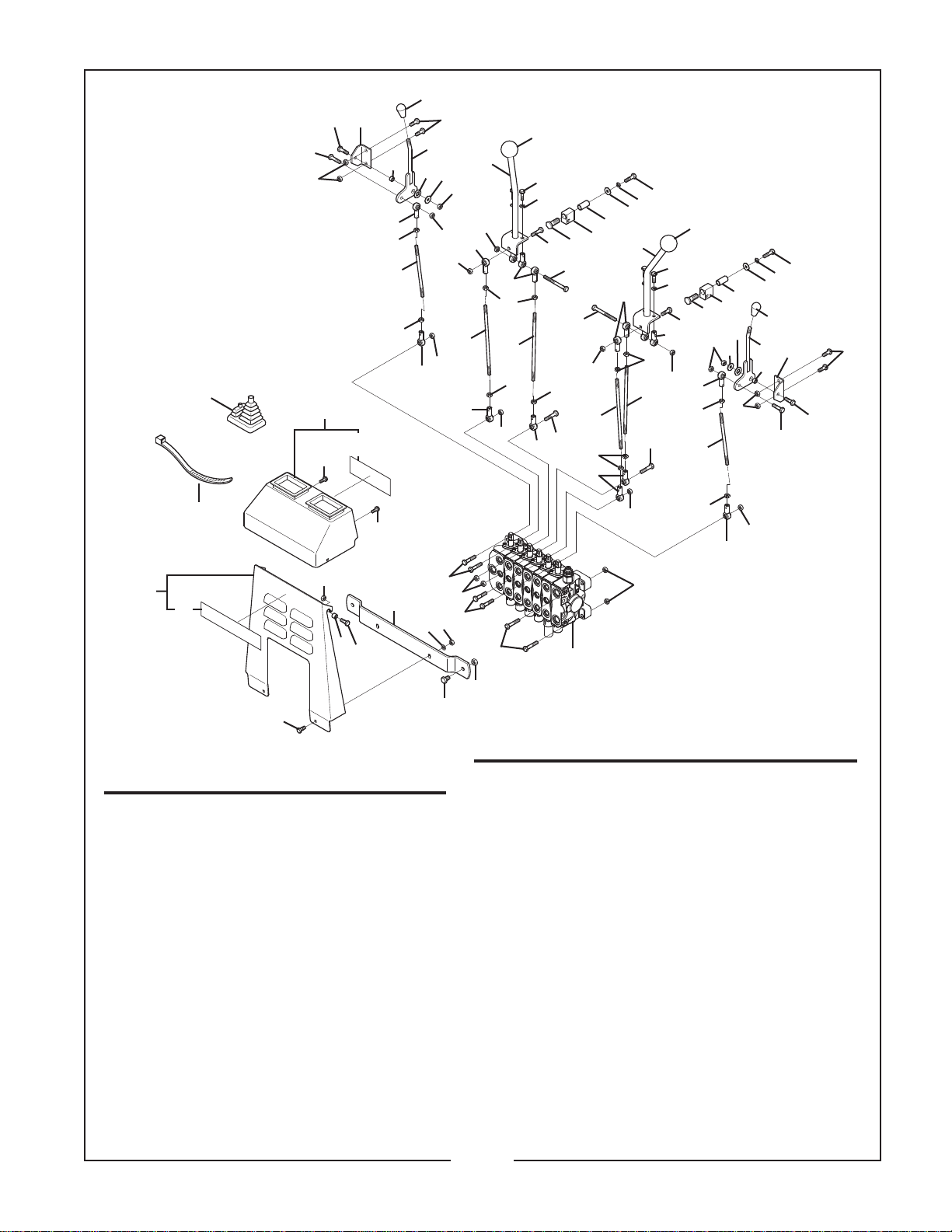
CONSOLE & CONTROLS
Model BH650, BH750, BH850, BH950
41
34
40
12
21
15
31
22
16
23
28
17
27
10
5
10
10
11
10
19
23
21
26
10
10
21
15
18
16
29
23
JULY, 2007
2
4
30
24
33
6
14
14
10
16
19
13
16
23
21
25
6
4
5
29
31
32
6
4
5
28
20
6
11
2
18
13
15
21
10
2
4
6
15
21
22
33
10
24
30
17
5
10
42
12
38
39
REF. PART
NO. NO.
1 –––– 2 Capscrew 5/16” x 3/4”
2 15004 6 Capscrew 5/16” x 1” NF
3 15602 6 Locknut 5/16”
4 –––– 6 Lockwasher 5/16”
5 –––– 6 Flatwasher 5/16”
6 19080 4 Capscrew 5/16” x 1-1/4” NF
7 –––– 2 Capscrew 3/8” x 3/4”
8 –––– 4 Capscrew 5/16” x 1-3/4”
9 20363 2 Locknut 3/8”
10 20962 12 Locknut 5/16” NF
11 44219 6 Capscrew 5/16” x 7/8” NF
12 44381 4 Capscrew, 1/4” x 3/4”
13 44541 6 Capscrew 5/16” x 1-1/2” NF
14 44829 2 Capscrew 5/16” x 3-1/4” NF
15 44890 6 Jam Nut 5/16” NF
16 44891 6 Jam Nut 5/16” LH NF
17 44903 2 Washer, Belleville 1/2” x 1”
18 50032785 2 Control Rod 8.63”
19 50032786 2 Control Rod 9.19”
20 50032788 2 Mounting Plate
QTY. DESCRIPTION
10
36
37
11
1
Washer Head, Self-Tapping
5
13
10
13
3
9
7
REF. PART
10
3
8
NO. NO.
21 50032790 4 Spherical Rod End, RH
22 50032792 2 Control Rod 6.81”
23 50032793 6 Spherical Rod End, LH
24 50032794 2 Swivel Block
25 50032795 1 Control Handle Weldment, LH
26 50032796 1 Control Handle Weldment, RH
27 50032797 1 Stabilizer Control Handle, RH
28 50032798 2 Small Knob
29 50032799 2 Control Handle Knob
30 50032805 2 Oilite Bearing 1/2” x 5/8” x 1-1/4”
31 50032807 2 Handle Bushing
32 50032809 1 Stabilizer Control Handle, LH
33 50032924 2 Pivot Bolt
34 50033325 1 Console Cover w/ Decal (All Models)
35 50032997 1 Hydraulic Valve, BH650, BH750
36 50033182 1 Valve Guard
37 50033196 2 Bushing, Front Cover
38 50033328 1 Front Cover w/ Decal (All Models)
39 50057094 1 Decal, Bush Hog
40 50102297 1 Decal, Directional Valve
41 50032993 2 Double Boot
42 50033322 2 Cable Tie
35
QTY. DESCRIPTION
50102278 1 Hydraulic Valve, BH850, BH950
16
10
23
14-1-1
Page 4
BUSH HOG / MATERIAL HANDLING REPAIR PARTS MANUAL
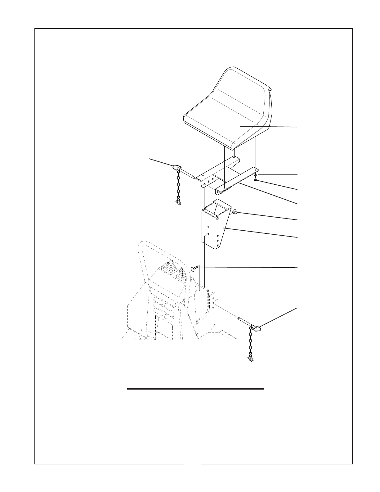
SEAT AND SEAT MOUNT
Model BH650, BH750, BH850, BH950
8
JULY, 2007
6
2
1
5
REF. PART
NO. NO.
1 –––– 4 Capscrew 5/16” x 3/4”
2 –––– 4 Lockwasher 5/16”
3 44534 1 Carriage Bolt 3/8” x 1-3/4”
4 50032777 1 Seat Bracket Weldment
5 50032782 1 Seat Rail Weldment
6 50032832 1 Seat
7 50033136 1 Seat Lock Knob
8 50033137 2 Seat Pin
QTY. DESCRIPTION
7
4
3
8
14-1-2
Page 5
BUSH HOG / MATERIAL HANDLING REPAIR PARTS MANUAL
40
39
26
1
2
25
39
45
24
13
38
30
37
31
38
10
37
44
23
21
35
22
JULY, 2007
39
45
12
5
37
27
38
43
2
42
37
5
15
36
9
4
16
31
5
19
17
4
41
39
11
28
39
1
2
6
3
20
29
4
45
5
4
18
1
38
4
35
32
5
5
See Bucket
and Related
Parts.
33
34
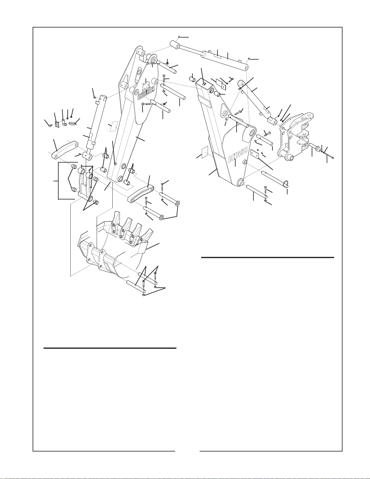
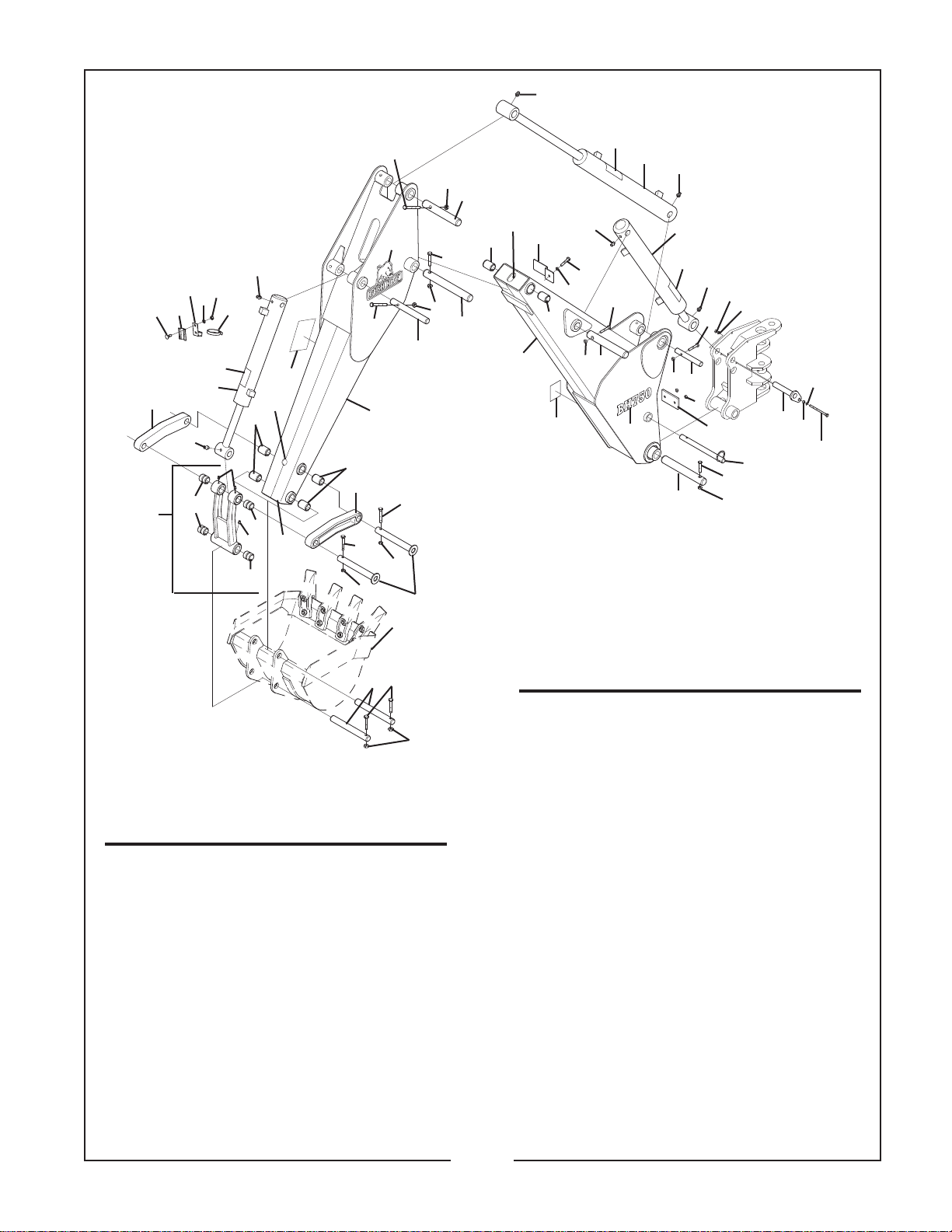
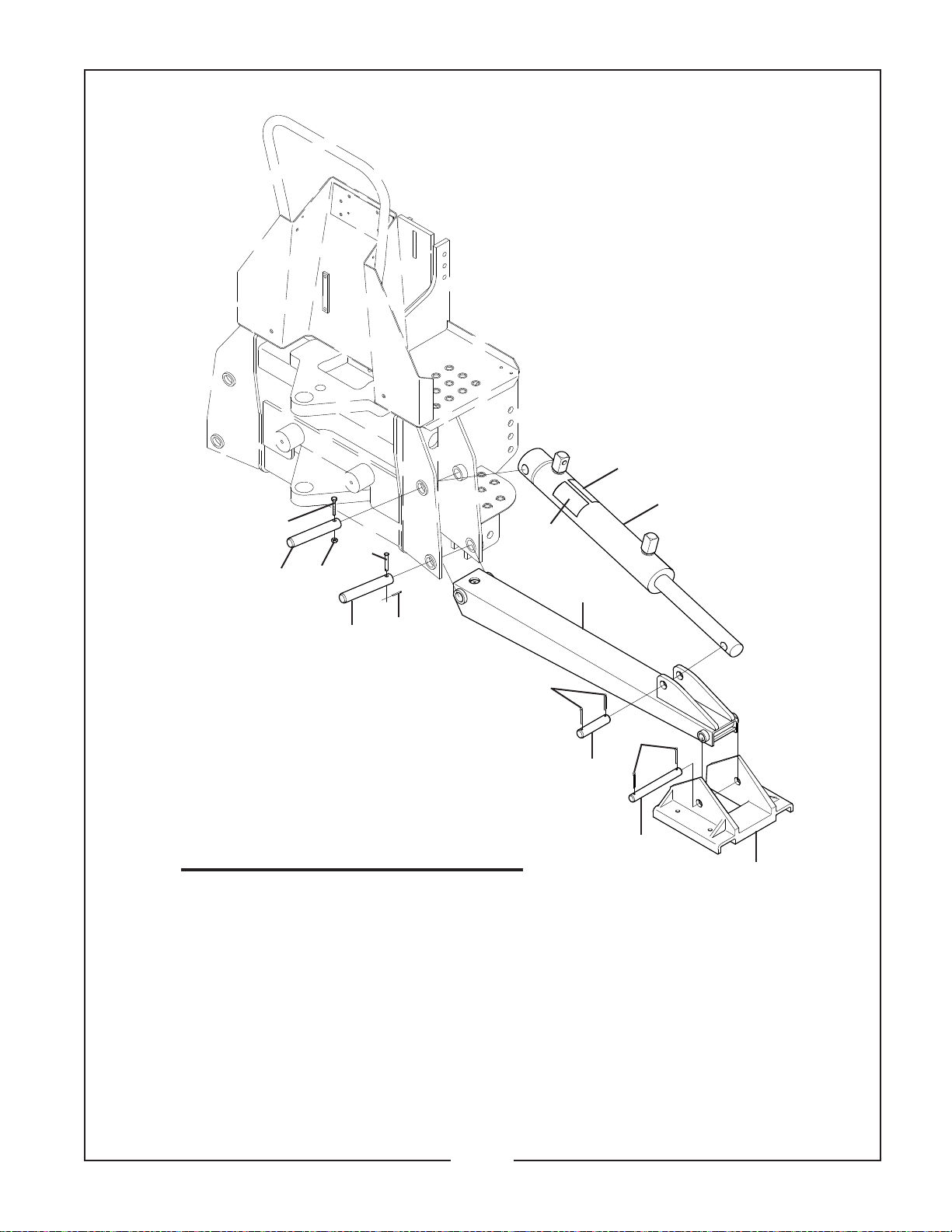
BOOM, DIPPERSTICK
& RELATED PARTS
MODEL BH650
REF. PART
NO. NO.
1 15602 5 Locknut 5/16”
2 –––– 4 Lockwasher 5/16”
3 –––– 1 Flatwasher 5/16”
4 –––– 5 Capscrew 3/8” x 2-1/2”
5 20363 10 Locknut 3/8”
6 50032807 1 Handle Bushing
7 50032982 2 Pin Weldment, Upper Link
8 50032998 1 Fastener Pin 1” x 8”
9 50033326 1 Boom Weldment w/ Decals
10 50033327 1 Dipper Stick w/ Decals
11 50033515 1 Boom Cylinder w/ Decal
12 50033513 1 Dipper Stick Cylinder w/ Decal
13 50033514 1 Bucket Cylinder w/ Decal
14 50032990 1 Pin 1.00 x 9.44”
15 50032988 1 Pin, 1.00 x 8.69”
QTY. DESCRIPTION
31
8
14
7
REF. PART
NO. NO.
16 50033222 1 Pin, 1.00 x 8.00”
17 50032986 1 Pin, 1.00 x 7.88”
18 50032989 1 Pin, 1.00 x 7.06”
19 50032985 1 Pin, 1.00 x 10.19”
20 50032994 1 Pin Weldment, Boom
21 50033135 1 Guide Link, RH
22 50033133 1 Guide Link, LH
23 50033192 1 Bucket Link Assembly
24 50033218 1 Hose Clamp
25 50033219 1 SMV Adapter
26 50101986 1 Bar, Sign Mount
27 50102295 1 Decal, Important
28 50033115 1 Plate, Hose Retention
29 –––– 1 Capscrew 5/16” x 4-3/4”
30 50033364 1 Decal, Warning
31 –––– 3 Capscrew 3/8” x 2-1/4”
32 50032987 2 Pin 1.00 x 8.06”
33 –––– 2 Capscrew 3/8” x 2-1/4”
34 20363 2 Locknut 3/8”
35 50033112 4 Bushing 1-1/4” x 1” x 1-3/8”
36 50033051 2 Decal, Model 650
37 50032976 6 Bushing 1-1/4” x 1 x 1.75
38 449 6 Grease Fitting
39 50028063 5 Grease Fitting
40 50057414 2 Bush Hog Decal
41 50033361 1 Grease Fitting 45°
42 50033188 1 Hose Clamp
43 –––– 1 Capscrew 5/16” x 3/4”
44 –––– 6 Carriage Bolt 5/16” X 3/4”
45 50100238 3 Decal, Warning
QTY. DESCRIPTION
5
14-2-1
Page 6
BUSH HOG / MATERIAL HANDLING REPAIR PARTS MANUAL
JULY, 2007
39
4
40
39
26
1
2
35
24
44
13
38
30
38
37
35
38
38
35
QTY. DESCRIPTION
37
22
4
5
31
10
5
See Bucket
and Related
Parts.
33
32
17
4
7
34
43
25
21
39
23
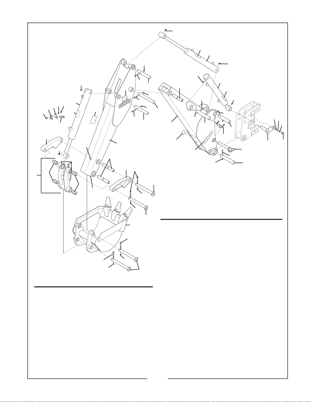
REF. PART
NO. NO.
1 15602 5 Locknut 5/16”
2 –––– 4 Lockwasher 5/16”
3 –––– 1 Flatwasher 5/16”
4 –––– 5 Capscrew 3/8” x 2-1/2”
5 20363 10 Locknut 3/8”
6 50032807 1 Handle Bushing
7 50032982 2 Pin Weldment, Upper Link
8 50032998 1 Fastener Pin 1” x 8”
9 50033524 1 Boom Weldment w/ Decal
10 50033526 1 Dipper Stick w/ Decal
11 50033528 1 Boom Cylinder w/ Decal
12 50033529 1 Dipper Stick Cylinder w/ Decal
13 50033530 1 Bucket Cylinder w/ Decal
14 50033158 1 Pin 1.25 x 9.56”
15 50033159 1 Pin, 1.25 x 8.50”
16 50033161 1 Pin, 1.25 x 7.93”
17 50033171 1 Pin, 1.00 x 8.12”
44
12
39
5
16
38
41
37
31
5
19
9
37
27
39
42
2
4
15
5
36
14
11
44
39
1
2
5
18
4
1
28
8
31
5
20
3
6
29
BOOM, DIPPERSTICK
& RELATED PARTS
MODEL BH750
REF. PART
NO. NO.
18 50033160 1 Pin, 1.25 x 6.81”
19 50033162 1 Pin, 1.25 x 10.19”
20 50033174 1 Pin Weldment, Boom
21 50033205 1 Guide Link, RH
22 50033207 1 Guide Link, LH
23 50033210 1 Bucket Link Assembly
24 50033218 1 Hose Clamp
25 50033219 1 SMV Adapter
26 50101986 1 Bar, Sign Mount
27 50102295 1 Decal, Important
28 50033115 1 Plate,Hose Retention
29 –––– 1 Capscrew 5/16” x 5”
30 50033364 1 Decal, Warning
31 –––– 3 Capscrew 3/8” x 2-1/4”
32 50032987 2 Pin 1.00 x 8.00”
33 –––– 2 Capscrew 3/8” x 2-1/4”
34 20363 2 Locknut 3/8”
35 50033112 4 Bushing 1-1/4” x 1” x 1-3/8”
36 50033216 2 Decal, Model BH750
37 50032976 6 Bushing 1-1/4” x 1 x 1.75
38 449 6 Grease Fitting
39 50028063 6 Grease Fitting
40 50057414 2 Bush Hog Decal
41 50033188 1 Hose Clamp
42 –––– 1 Capscrew 5/16” x 3/4”
43 –––– 2 Carriage Bolt 5/16” X 3/4”
44 50100238 3 Decal, Warning
QTY. DESCRIPTION
14-2-2
Page 7
BUSH HOG / MATERIAL HANDLING REPAIR PARTS MANUAL
JULY, 2007
38
29
25
25
29
19,20
41,42,10
39
8
17
38
24
16
23
22
13
7
21
20
39
38
26
42
41
27
15
40
3
30
5
29
28
38
31
30
31
35
1
32
31
34
19
11
20
19
20
12
19
11
4
6
14
33
19
2
37
20
9
36
18
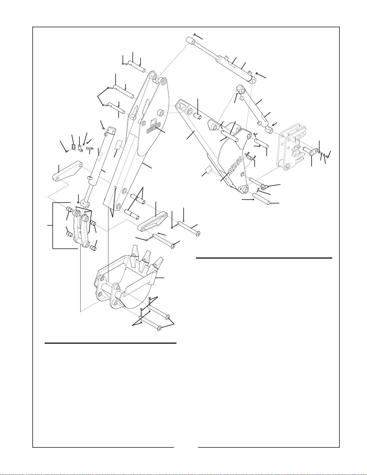
BOOM, DIPPERSTICK
& RELATED PARTS
20
MODEL BH850
43
20
REF. PART
NO. NO.
1 50033459 1 Dipperstick w/ Decals
2 50033460 1 Boom w/ Decals
3 50033168 1 R.H. Guide Link
4 50033260 1 L.H. Guide Link
5 50033166 1 Bucket Link Assembly
6 –––– 2 Capscrew 3/8” x 3” Gr.5
7 50101970 1 Pin 1.50 x 9.02”
8 50101968 1 Pin 1.50 x 7.13”
9 50101966 1 Pin 1.50 x 9.06”
10 50102233 1 Hose Clamp
11 50101964 2 Pin 1.25 x 8.61”
12 50101949 1 Pin 1.25 x 10.68”
13 50101981 1 Plated Pin Assembly
14 50101962 4 Plated Link Pin
15 50101986 1 Bar Sign Mount
16 50102230 1 Spacer Bushing
QTY. DESCRIPTION
20
20
see Note
43
14
14
REF. PART
NO. NO.
17 –––– 1 Capscrew 1/2 x 3” G8
18 50020921 2 Locknut 1/2”
19 –––– 5 Capscrew 3/8” x 2-3/4” G5
20 20363 11 Locknut 3/8”
21 –––– 1 Capscrew 1/2 x 1” Gr.5
22 –––– 1 Lockwasher 1/2”
23 –––– 1 Flatwasher 1/2”
24 50102241 1 Hitch Pin
25 50033483 2 Dipper/Boom Cylinder w/ Decal
26 50033484 1 Bucket Cylinder w/ Decal
27 50033219 1 SMV Adapter
28 50033218 1 Hose Clamp
29 50100238 3 Decal, Caution
30 50101778 4 Spring Bushing 2.25”
31 449 5 Grease Fitting
32 50101780 2 Spring Bushing, 7.25”
33 50101781 1 Spring Bushing 6.5”
34 50057414 2 Decal, Bush Hog
35 50033364 1 Decal, Warning
36 50033426 2 Decal, Model Number
37 50102295 1 Decal, Important
38 50028063 4 Grease Fitting
39 50102565 2 Grease Fitting
40 –––– 2 Carriage Bolt 5/16” x 3/4”
41 –––– 3 Lockwasher 5/16”
42 15528 3 Locknut 5/16”
43 –––– 2 Capscrew 3/8” x 2-1/4”
Note: See separate parts listing for bucket parts.
QTY. DESCRIPTION
14-2-3
Page 8
BUSH HOG / MATERIAL HANDLING REPAIR PARTS MANUAL
11
21
22
13
22
JULY, 2007
41
17
27
42
7
41
39
30
16
38
3
5
REF. PART
35
NO. NO.
1 50033491 1 Dipper Stick w/ Decals
2 50033493 1 Boom w/ Decals
3 50033262 1 R.H. Guide Link
4 50033264 1 L.H. Guide Link
5 50033215 1 Bucket Link Assembly
6 50033364 1 Decal, Warning
7 –––– 4 Capscrew 3/8” x 3”
8 50101970 1 Pin 1.50” x 9.02”
9 50101968 1 Pin 1.50” x 7.13”
10 50101966 1 Pin 1.50” x 9.06”
11 50102418 1 Pin 1.50” x 8.60”
12 50101964 1 Pin 1.25” x 8.61”
13 50102419 1 Pin 1.50” x 10.68”
14 50102420 1 Plated Pin Assembly
15 50101962 4 Plated Link Pin
16 50101986 1 Bar Sign Mount
40
17
31
41
34
35
QTY. DESCRIPTION
22
12
6
28
43
34
7
22
1
4
37
22
see Note
45
7
15
14-2-4
33
2
32
22
15
REF. PART
NO. NO.
Note: See separate parts listing for bucket parts.
27
15
42
21
10
22
36
22
29,39,40
20
BOOM, DIPPERSTICK
21
17
41
18
23
9
26
19
8
14
25
24
& RELATED PARTS
MODEL BH950
QTY. DESCRIPTION
17 50100238 3 Decal, Caution
18 50102230 1 Spacer Bushing
19 –––– 1 Capscrew 1/2” x 3”
20 50020921 1 Locknut 1/2”
21 –––– 3 Capscrew 3/8” x 2-3/4”
22 20363 11 Locknut 3/8”
23 –––– 1 Capscrew 1/2” x 1”
24 –––– 1 Lockwasher 1/2”
25 –––– 1 Flatwasher 1/2”
26 50102241 1 Hitch Pin
27 50033495 2 Dipper/Boom Cylinder w/ Decal
28 50033496 1 Bucket Cylinder w/ Decal
29 50102233 1 Hose Clamp
30 50033219 1 SMV Adaptor
31 50033218 1 Hose Clamp
32 50102295 1 Important Decal
33 50101998 1 Spring Bushing
34 449 6 Grease Fitting
35 50101778 4 Spring Bushing 2.25”
36 50033427 2 Decal, Model BH950
37 50057414 2 Decal, Bush Hog
38 –––– 2 Carriage Bolt 5/16” x 3/4”
39 –––– 4 Lockwasher 5/16”
40 15528 4 Locknut 5/16”
41 50028063 4 Grease Fitting
42 50102565 2 Grease Fitting
43 50101780 2 Spring Bushing
44 50101998 1 Spring Bushing
45 –––– 2 Capscrew 3/8” x 2-1/4”
Page 9
BUSH HOG / MATERIAL HANDLING REPAIR PARTS MANUAL
SEPTEMBER, 2003
3
4
2
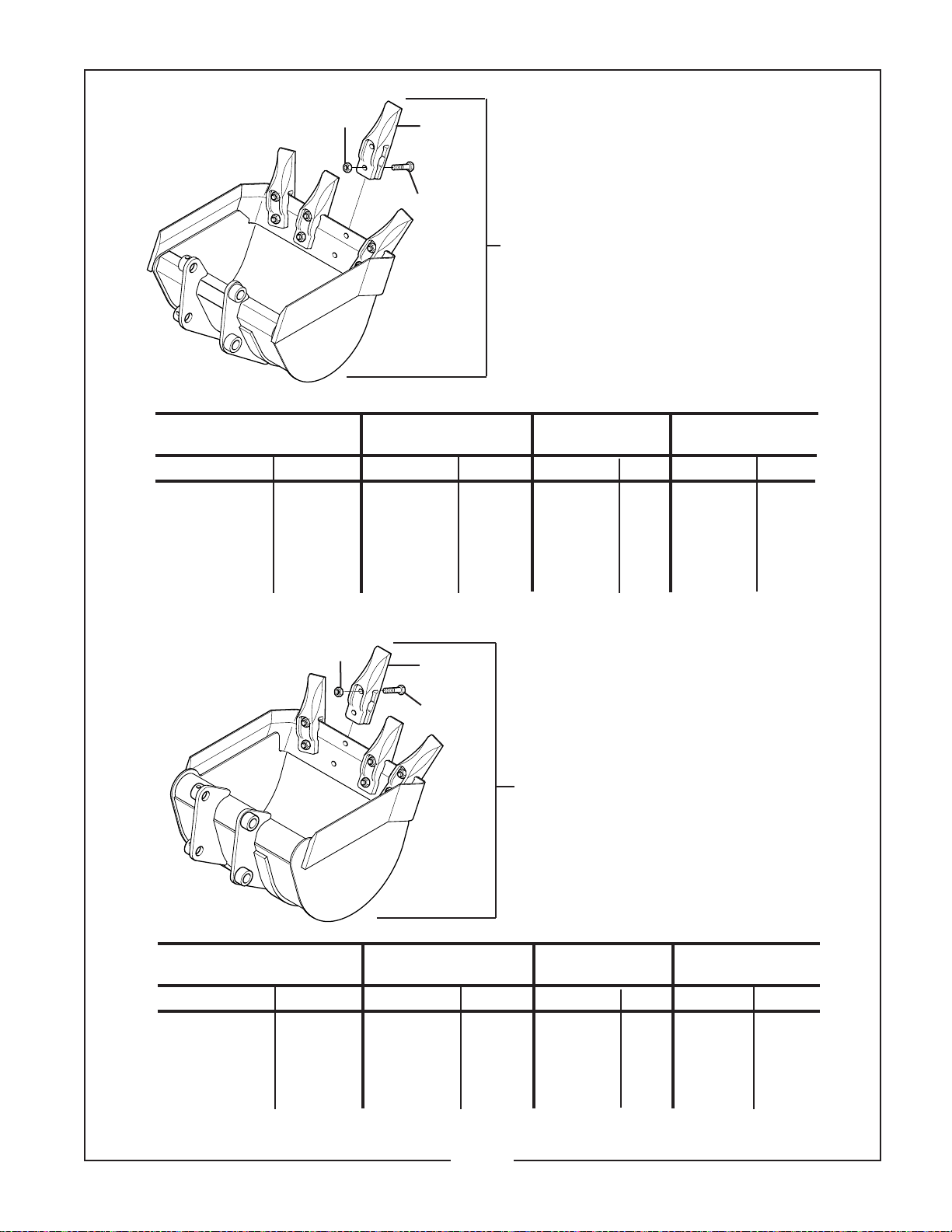
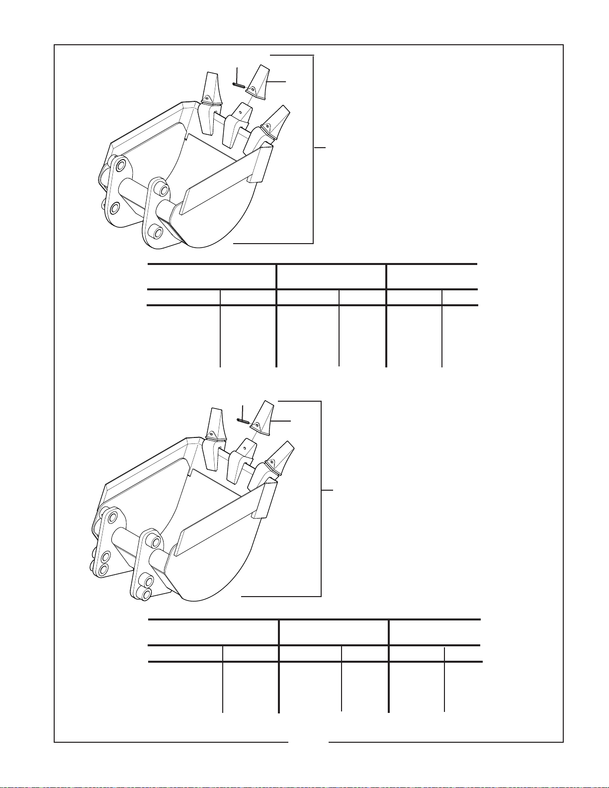
REGULAR DUTY BUCKETS
For Models: BH650, BH750
1
Ref. No. 1 Ref. No. 2 Ref. No. 3 Ref. No. 4
Bucket Assembly HHCS 1/2” X 1-3/4” Gr.5 Locknut 1/2” Gr.C Digging Point
Description Part No. No. Qty. No. Qty. No. Qty.
9” Regular Duty 50032946 –––– 4 9161600 4 50032927 2
12” Regular Duty 50032951 –––– 6 9161600 6 50032927 3
16” Regular Duty 50032939 –––– 6 9161600 6 50032927 3
18” Regular Duty 50032956 –––– 8 9161600 8 50032927 4
20” Regular Duty 50032961 –––– 8 9161600 8 50032927 4
24” Regular Duty 50032966 –––– 8 9161600 8 50032927 4
36” Regular Duty 50032971 –––– 12 9161600 12 50032927 6
3
4
2
COMMERCIAL DUTY BUCKETS
For Models: BH650, BH750
1
Ref. No. 1 Ref. No. 2 Ref. No. 3 Ref. No. 4
Bucket Assembly HHCS 1/2” X 1-3/4” Gr.5 Locknut 1/2” Gr.C Digging Point
Description Part No. No. Qty. No. Qty. No. Qty.
9” Commercial 50033005 –––– 4 9161600 4 50032927 2
12” Commercial 50033009 –––– 6 9161600 6 50032927 3
16” Commercial 50033013 –––– 6 9161600 6 50032927 3
18” Commercial 50033017 –––– 8 9161600 8 50032927 4
20” Commercial 50033021 –––– 8 9161600 8 50032927 4
24” Commercial 50033025 –––– 8 9161600 8 50032927 4
14-3-1
Page 10
BUSH HOG / MATERIAL HANDLING REPAIR PARTS MANUAL
2
Ref. No. 1 Ref. No. 2 Ref. No. 3
Bucket Assembly Roll Pin 3/8” x 2-1/4” Tooth Tip
Description Part No. No. Qty. No. Qty.
12” Regular Duty 50102487 50009171 3 50101997 3
16” Regular Duty 50102486 50009171 3 50101997 3
18” Regular Duty 50102485 50009171 3 50101997 3
20” Regular Duty 50102484 50009171 4 50101997 4
24” Regular Duty 50102301 50009171 4 50101997 4
36” Regular Duty 50102499 50009171 6 50101997 6
SEPTEMBER, 2003
3
REGULAR DUTY BUCKETS
1
For Models: BH850, BH950
2
3
COMMERCIAL DUTY BUCKETS
For Models: BH850, BH950
1
Ref. No. 1 Ref. No. 2 Ref. No. 3
Bucket Assembly Roll Pin 3/8” x 2-1/4” Tooth Tip
Description Part No. Part No. Qty. Part No. Qty.
12” Commercial 50102483 50009171 3 50101997 3
16” Commercial 50102482 50009171 3 50101997 3
18” Commercial 50102481 50009171 3 50101997 3
20” Commercial 50102480 50009171 4 50101997 4
24” Commercial 50102300 50009171 4 50101997 4
14-3-2
Page 11
BUSH HOG / MATERIAL HANDLING REPAIR PARTS MANUAL
November, 2004
12
12A
27
28
11
28
25
6
18
17
29
7
10
14
25
6
11
13
5 3 4 16
10
26
1
9
8
15
14
1
2
20
2
24
22
19
21
27
23
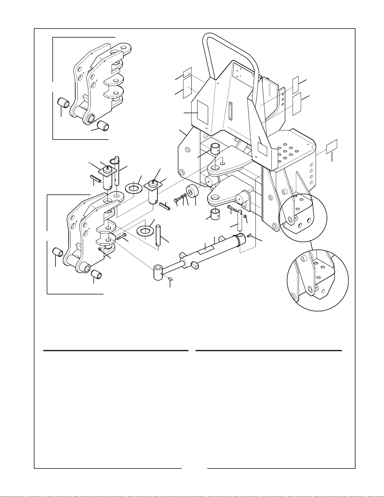
MAIN FRAME, SWING FRAME & RELATED PARTS
Model BH650, BH750
S/N 3-00001 and Above
REF. PART
NO. NO.
1 –––– 4 Capscrew 5/16” x 2”
2 15602 13 Locknut 5/16”
3 –––– 2 Lockwasher 3/8”
4 –––– 2 Flatwasher 3/8”
5 –––– 2 Capscrew 3/8” x 1”
6 44824 2 Roll Pin 1/2” x 2-1/2”
7 50033323 1 Mainframe w/ Decals, BH650
50033650 1 Mainframe w/ Decals, BH750
8 50033512 2 Swing Cylinder w/ Decal
9 50032923 2 Pin, 1.00 x 4.56”
10 50033030 2 Bearing, Garlock
11 50032917 2 Swing Pin Weldment
12 50032841 1 Swing Frame Assembly, BH650
12A 50033145 1 Swing Frame Assembly, BH750
13 50033190 2 Pin, 1.00 x 4.66”
14 50102244 2 Flatwasher 1-3/4” Narrow, Hard
QTY. DESCRIPTION
Old Style Mainframe
S/N Below 3-00001
REF. PART
NO. NO.
15 50033247 1 Fast Pin 1.00 x 4.50”
16 50101785 2 Rubber Bumper
17 50102292 1 Decal, Danger
18 50102293 1 Decal, Warning
19 50102294 1 Caution Decal, BH650
50033476 1 Caution Decal, BH750
20 50102296 1 Decal, Important
21 50033282 1 Decal, Inlet-Outlet
22 50033366 1 Decal, Warning
23 50028063 2 Grease Fitting
24 50033361 2 Grease Fitting
25 449 2 Grease Fitting
26 50100238 2 Decal, Caution
27 50032976 2 Bushing 1-1/4 x 1 x 1.75”
28 50033096 2 Bushing 1-1/2” x 1-1/4” x 1-3/4”
29 50033364 1 Decal, Warning
14-4-1
QTY. DESCRIPTION
Page 12
BUSH HOG / MATERIAL HANDLING REPAIR PARTS MANUAL
November, 2004
20
17
1A
29
27
22
16
18
15
19
23
11
13
4
9
6
16
15
23
6
1
10
12
24
7
8
7
9
5
14
10
25
3
21
2
28
27
26
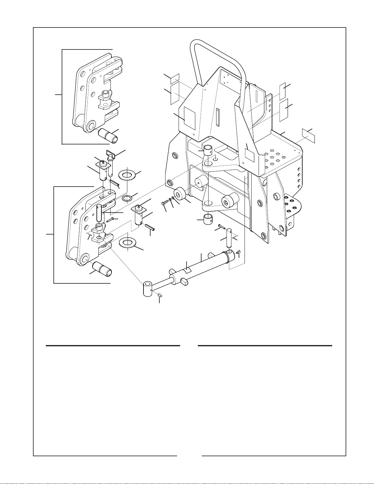
MAIN FRAME, SWING FRAME & RELATED PARTS
Models BH850, BH950
REF. PART
NO. NO.
1 50101897 1 Swing Assembly, BH850
1A 50102408 1 Swing Assembly, BH950
2 50033473 1 Mainframe w/ Decals, BH850
50033649 1 Mainframe w/ Decals, BH950
3 50033366 1 Decal, Warning
4 50101985 2 Pin 1.13 x 4.65
5 50102271 2 Pin 1.13 x 5.22
6 50101976 2 Swing Pin Weldment
7 50033030 2 Garlock Ox Bushing
8 50101785 2 Rubber Bumper
9 50020592 4 Clevis Pin 5/16” x 2”
10 15662 4 Cotter Pin 1/8” x 1”
11 –––– 2 Capscrew 3/8” x 1-1/4”
12 –––– 2 Flatwasher 3/8”
13 –––– 2 Lockwasher 3/8”
14 50033482 2 Swing Cylinder Assy.
QTY. DESCRIPTION
REF. PART
NO. NO.
15 50102244 2 Flatwasher 1-3/4”
16 44824 2 Roll Pin 1/2” x 2-1/2”
17 50102292 1 Danger Decal
18 50102289 1 Hitch Pin 1” x 4-1/4”
19 50102291 3 Shim Washer
20 50102293 1 Warning Decal
21 50102523 1 Caution Decal, BH850
50033477 1 Caution Decal, BH950
22 50102296 1 Important Decal
23 449 2 Grease Fitting
24 50100238 2 Decal, Caution
25 50033361 2 Grease Fitting
26 50028063 2 Grease Fitting
27 50101782 1 Spring Bushing
28 50102522 1 Hydraulic Decal
29 50033364 1 Decal, Warning
QTY. DESCRIPTION
14-4-2
Page 13
BUSH HOG / MATERIAL HANDLING REPAIR PARTS MANUAL
SEPTEMBER, 2003
13
7
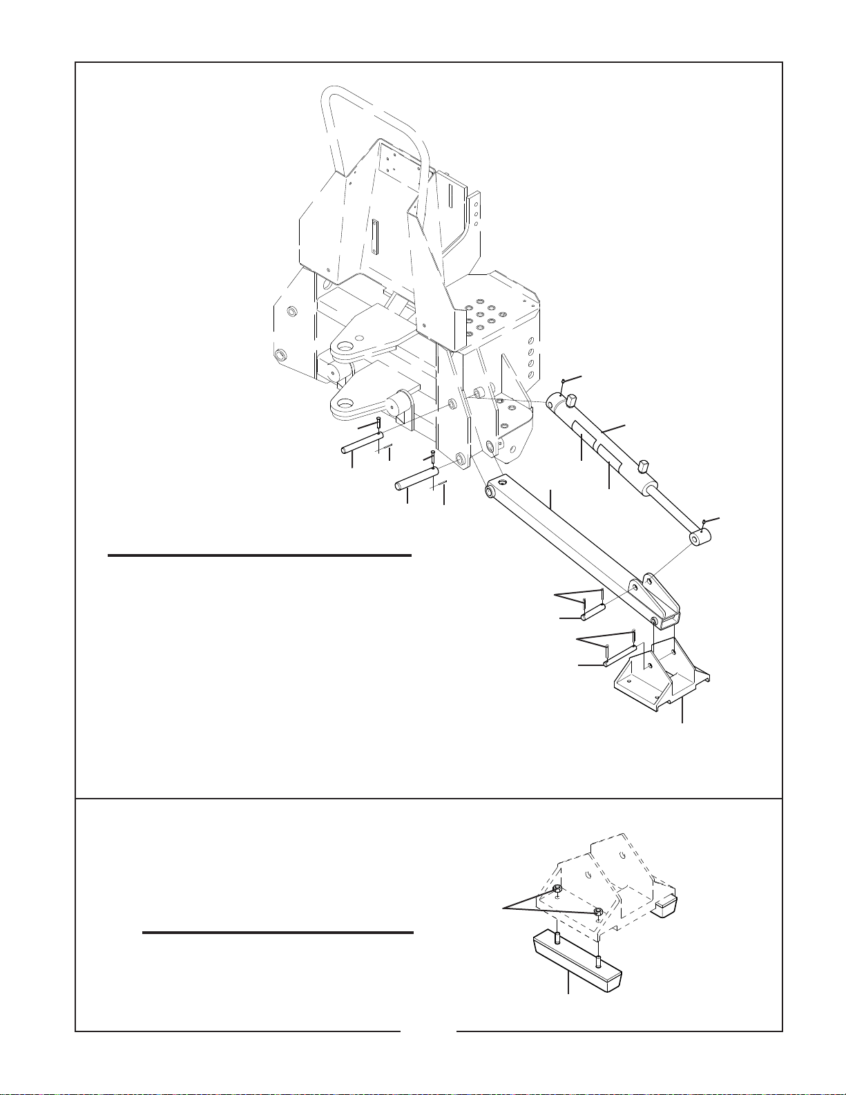
STABILIZER
3
Model BH650, BH750
REF. PART
NO. NO.
1 15474 4 Cotter Pin 1/4” x 1-3/4”
2 50033324 2 Stabilizer Cylinder w/ Decals
3 50032991 2 Pin 3/4” x 6-1/2”
4 50033179 2 Pin 5/8” x 5-3/8”
5 50033198 2 Stabilizer Foot
6 50032811 2 Stabilizer Weldment
7 97406 2 Clevis Pin 5/16” x 1-1/2”
8 50033478 2 Pin, 1” x 6-1/2”
9 21020614 4 Cotter Pin 3/16” x 1-1/2”
10 50033567 2 Clevis Pin 5/16” x 1-3/4”
11 21020310 4 Cotter Pin 3/32” x 1”
12 50032992 2 Pin, 3/4” x 3-5/8”
13 50028063 4 Grease Fitting
14 50102298 2 Decal, Important
15 50100238 2 Decal, Caution
QTY. DESCRIPTION
11
2
10
8
11
15
6
14
13
9
12
1
4
5
50033330 FOOT PAD KIT
Model BH650, BH750, BH850, BH950
REF. PART
NO. NO.
1 50033224 4 Foot Pad
2 20363 8 Lock Nut 3/8”
QTY. DESCRIPTION
2
1
14-5-1
Page 14
BUSH HOG / MATERIAL HANDLING REPAIR PARTS MANUAL
12
6
13
2
November, 2004
11
1
10
5
2
8
STABILIZER
Model BH850, BH950
REF. PART
NO. NO.
1 50033475 2 Stabilizer Cylinder w/ Decals
2 50102245 4 Pin 1-1/8” x 7”
3 50101974 2 Pin .88” x 7.37”
4 50033173 2 Stabilizer Foot
5 50101890 2 Stabilizer Weldment
6 50020592 2 Clevis Pin 5/16” x 2”
7 20167 8 Cotter Pin 3/16” x 2”
8 15662 2 Cotter Pin 1/8” x 1”
9 50101972 2 Pin, 1” x 4-1/8”
10 50102298 2 Decal, Important
11 50100238 2 Decal, Caution
12 –––– 2 Capscrew 5/16” x 2”
13 15602 2 Lock Nut 5/16”
QTY. DESCRIPTION
7
7
9
3
4
14-5-2
Page 15
BUSH HOG / LAND MAINTENANCE REPAIR PARTS MANUAL
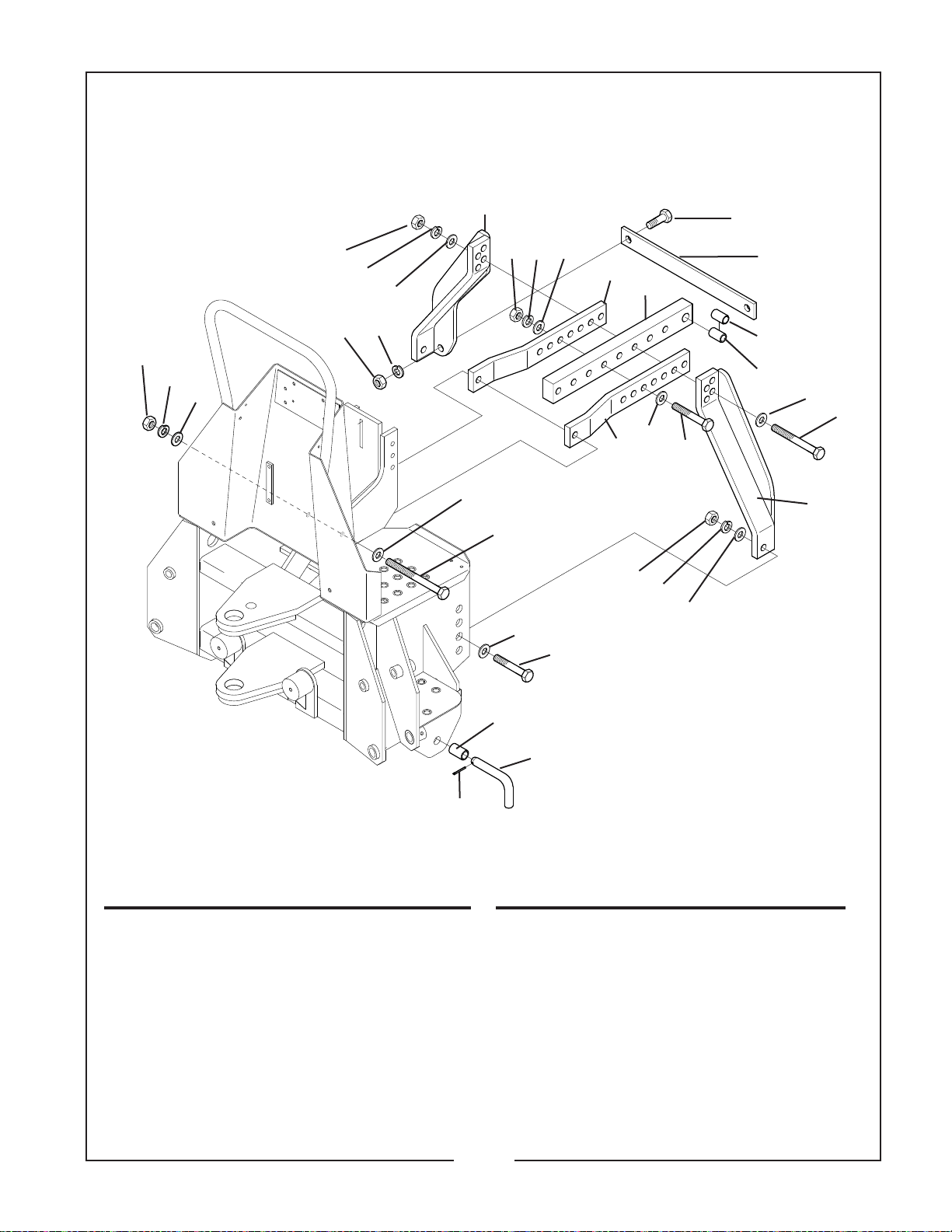
50033068 3-POINT LIFT KIT
Model BH650, BH750, BH850, BH950
November, 2004
14
12
11
14
12
15 13
11
11
1
14 12
16
21
11
19
20
3
4
11
3
23
18
21
22
10
6
5
11
17
2
REF. PART
NO NO
1 50101936 1 3-Point Mount Weldment, RH
2 50101937 1 3-Point Mount Weldment, LH
3 50101941 2 3-Point Angle Mount
4 50101942 1 3-Point Mount
5 50032830 1 Bushing 1” OD x 3/4” ID x 1.62”
6 50032831 1 Bushing 1” OD x 13/16” ID x 1.62”
7 50032834 2 3-Point Lower Bushing
8 50032825 2 3-Point Plated Pin
9 50005860 2 Cotter Pin .148”
10 50101943 1 Bar, Mount
11 –––– 10 Flatwasher 3/4”
12 –––– 5 Lockwasher 3/4”
QTY. DESCRIPTION
7
9
REF. PART
NO NO
13 –––– 2 Lockwasher 1/2”
14 92816 5 Hex Nut 3/4” NF
15 15507 2 Hex Nut 1/2” NF
16 44935 1 Capscrew 3/4” x 7-1/2” G8 NF
17 44934 1 Capscrew 3/4” x 6” NF
18 44826 1 Capscrew 3/4” x 4-1/2” G8 NF
19 44933 2 Capscrew 7/8” x 2-1/2” G8 NF
20 44032 2 Capscrew 1/2” x 1-1/2” NF
21 –––– 4 Flatwasher 7/8”
22 –––– 2 Lockwasher 7/8”
23 –––– 2 Hex Nut 7/8” NF
14-6-1
8
QTY. DESCRIPTION
Page 16

Page 17
BUSH HOG / MATERIAL HANDLING REPAIR PARTS MANUAL
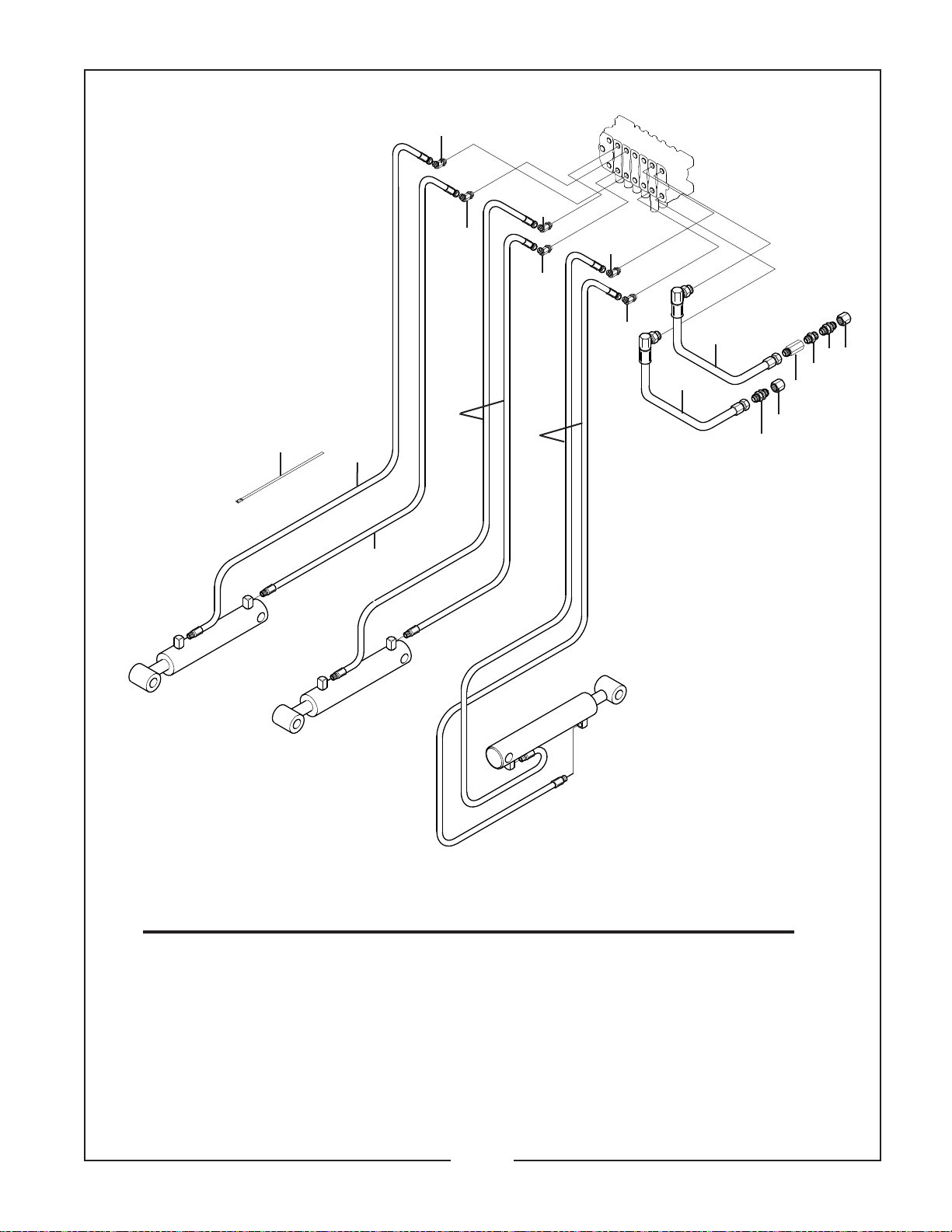
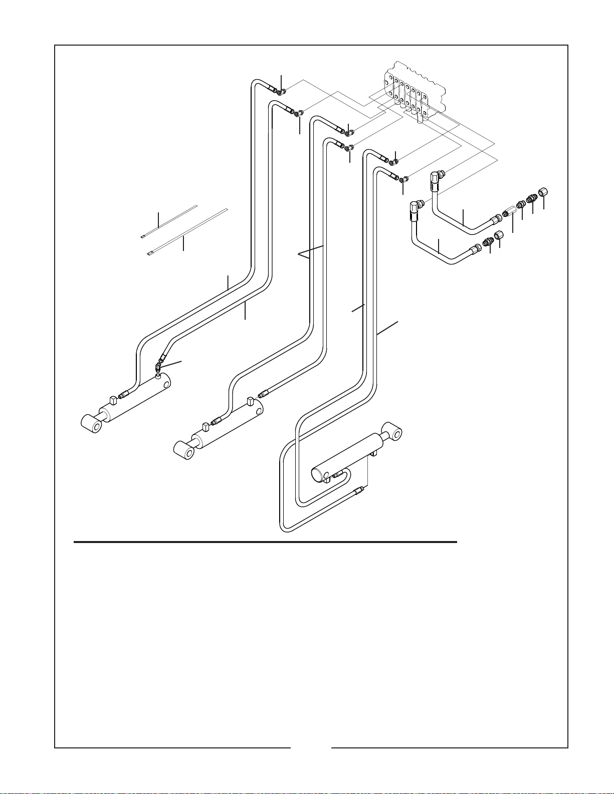
HYDRAULIC FITTINGS
FOR DIPPERSTICK,
BOOM & BUCKET
Model BH650
4
10
November, 2004
1
1
1
1
8
7
1
1
6
11
2
6
2
3
5
11
9
Bucket
Dipperstick
Boom
REF. PART
NO. NO.
1 25H41174 6 45° Elbow 9/16” JICM x 9/16” ORBM
2 25H47052 2 Straight Bulkhead Union 3/4” JICM
3 25H47624 1 Straight Adapter 3/4” JICF Swivel x 3/4” ORBM
4 50020573 3 Nylon Cable Tie
5 50033047 1 Check Valve
6 50033127 2 Hydraulic Hose .875” ORBM 90° Swivel x 3/4” JICF Swivel x 20”
7 50033118 2 Hydraulic Hose w/ Sleeve 9/16” JICF Swivel x 9/16” ORBM Swivel x 59” (Boom)
8 50033119 2 Hydraulic Hose w/ Sleeve 9/16” JICF Swivel x 9/16” ORBM Swivel x 68” (Dipperstick)
9 50033200 1 Hydraulic Hose w/ Sleeve 9/16” JICF Swivel x 9/16” ORBM Swivel x 98” (Bucket)
10 50033120 1 Hydraulic Hose w/ Sleeve 9/16” JICF Swivel x 9/16” ORBM Swivel x 114” (Bucket)
11 50033705 2 3/4” – 16 JIC Cap, Shipping
QTY. DESCRIPTION
14-7-1
Page 18
BUSH HOG / MATERIAL HANDLING REPAIR PARTS MANUAL
SEPTEMBER, 2003
1
1
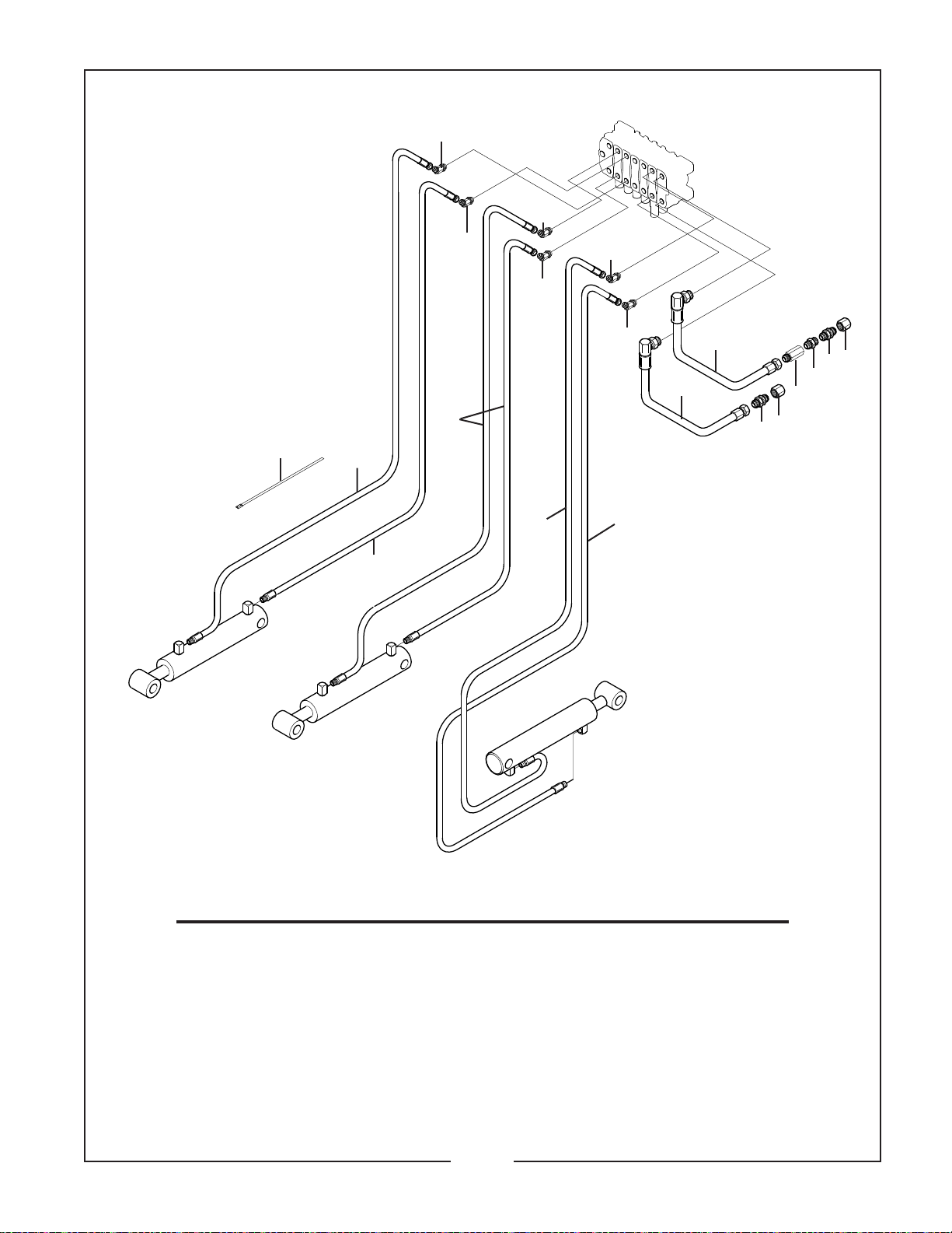
HYDRAULIC FITTINGS
FOR DIPPERSTICK,
BOOM & BUCKET
Model BH750
4
Bucket
10
1
1
8
11
9
1
1
7
6
12
2
6
2
3
5
12
Dipperstick
Boom
REF. PART
NO. NO.
1 25H41174 6 45° Elbow 9/16” JICM x 9/16” ORBM
2 25H47052 2 Straight Bulkhead Union 3/4” JICM
3 25H47624 1 Straight Adapter 3/4” JICF Swivel x 3/4” ORBM
4 25H47571 3 Nylon Cable Tie
5 50033047 1 Check Valve
6 50033127 2 Hydraulic Hose .875 ORBM 90° Swivel x 3/4” JICF Swivel x 20”
7 50033211 1 Hydraulic Hose w/ Sleeve 9/16” JICF Swivel x 9/16” ORBM Swivel x 81”
8 50033212 2 Hydraulic Hose w/ Sleeve 9/16” JICF Swivel x 9/16” ORBM Swivel x 82.50”
9 50033213 1 Hydraulic Hose w/ Sleeve 9/16” JICF Swivel x 9/16” ORBM Swivel x 113”
10 50033214 1 Hydraulic Hose w/ Sleeve 9/16” JICF Swivel x 9/16” ORBM Swivel x 131”
11 50033244 1 Hydraulic Hose w/ Sleeve 9/16” JICF Swivel x 9/16” ORBM Swivel x 74”
12 50033705 2 3/4” – 16 JIC Cap, Shipping
QTY. DESCRIPTION
14-7-2
Page 19
BUSH HOG / MATERIAL HANDLING REPAIR PARTS MANUAL
November, 2004
1
HYDRAULIC FITTINGS
FOR DIPPERSTICK,
BOOM & BUCKET
Model BH850, BH950
13
4
12
10
1
1
1
8
11
9
1
1
7
6
14
2
6
2
3
5
14
Bucket
Dipperstick
Boom
REF. PART
NO. NO.
1 25H41174 6 45° Elbow 9/16” OMR-9/16” JMR
2 25H47052 2 Straight Bulkhead Union 3/4” JIC
3 25H47624 1 Straight Adapter 3/4” OMS 3/4” JFR
4 50020573 3 Nylon Cable Tie, 30.62” Long
5 50033047 1 Check Valve
6 50101832 2 Hydraulic Hose .875 ORBM Swivel x 3/4” JICF Swivel x 25.88”
7 50101833 1 Hydraulic Hose w/ Sleeve 9/16” JICF Swivel x 3/4” ORBM Swivel x 76.32”
8 50101834 2 Hydraulic Hose w/ Sleeve 9/16” JICF Swivel x 3/4” ORBM Swivel x 85.32” (BH850)
50102252 2 Hydraulic Hose w/ Sleeve 9/16” JICF Swivel x 3/4” ORBM Swivel x 95.32” (BH950)
9 50101836 1 Hydraulic Hose w/ Sleeve 9/16” JICF Swivel x 3/4” JICF Swivel x 115.03” (BH850)
50102250 1 Hydraulic Hose w/ Sleeve 9/16” JICF Swivel x 3/4” JICF Swivel x 125” (BH950)
10 50101835 1 Hydraulic Hose w/ Sleeve 9/16” JICF Swivel x 3/4” ORBM Swivel x 130.35” (BH850)
50102249 1 Hydraulic Hose w/ Sleeve 9/16” JICF Swivel x 3/4” ORBM Swivel x 152” (BH950)
11 50102049 1 Hydraulic Hose w/ Sleeve 9/16” JICF Swivel x 3/4” ORBM Swivel x 74.32” (BH850)
50102251 1 Hydraulic Hose w/ Sleeve 9/16” JICF Swivel x 3/4” ORBM Swivel x 81.32” (BH950)
12 25H43808 1 45° Fitting 3/4” JICM x 3/4” ORBM
13 25H47571 4 Nylon Cable Tie, 14.50” Long
14 50033705 2 Shipping Cap, 3/4” – 16 JIC
QTY. DESCRIPTION
14-7-3
Page 20

Page 21
BUSH HOG / MATERIAL HANDLING REPAIR PARTS MANUAL
6
6
6
6
4
3
4
3
SEPTEMBER, 2003
6
6
2
1
7
Swing
5
Stabilizer
5
Swing
Stabilizer
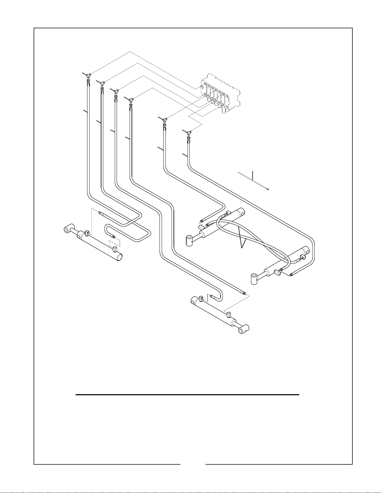
HYDRAULIC FITTINGS
FOR SWING & STABILIZER
Model BH650, BH750
REF. PART
NO. NO.
1 50033121 1 Hydraulic Hose, 9/16” - 18 ORBM x 9/16” - 18 JICF x 28”
2 50033122 1 Hydraulic Hose, 9/16” - 18 ORBM x 9/16” - 18 JICF x 24”
3 50033123 2 Hydraulic Hose, 9/16” - 18 ORBM x 9/16” - 18 JICF x 33”
4 50033124 2 Hydraulic Hose, 9/16” - 18 ORBM x 9/16” - 18 JICF x 41”
5 50033125 2 Hydraulic Hose, 9/16” - 18 ORBM x 9/16” - 18 ORBM x 17-1/2”
6 53338 6 90° Elbow 9/16” OMR x 9/16” JMR
7 25H47571 3 Nylon Cable Tie
QTY. DESCRIPTION
14-8-1
Page 22
BUSH HOG / MATERIAL HANDLING REPAIR PARTS MANUAL
4
4
4
4
2
2
2
2
SEPTEMBER, 2003
4
4
1
1
5
Swing
Stabilizer
3
Swing
Stabilizer
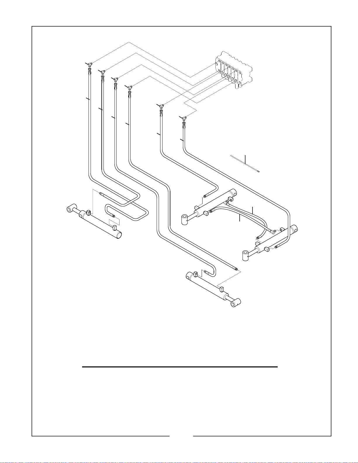
HYDRAULIC FITTINGS
FOR SWING & STABILIZER
Model BH850, BH950
REF. PART
NO. NO.
1 50033713 2 Hydraulic Hose, 9/16” ORBM Rigid x 9/16” JICF Swivel x 30”
2 50101841 4 Hydraulic Hose, 9/16” ORBM Swivel x 9/16” JICF Swivel x 54.78”
3 50033709 2 Hydraulic Hose, 9/16” ORBM Rigid x 9/16” ORBM Swivel x 23.75”
4 53338 6 90° Elbow 9/16” JICM x 9/16” ORBM
5 25H47571 4 Nylon Cable Tie
QTY. DESCRIPTION
14-8-2
Page 23
BUSH HOG / MATERIAL HANDLING REPAIR PARTS MANUAL
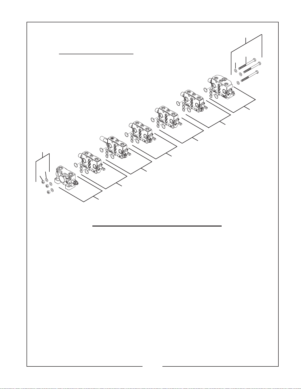
50032997 CONTROL VALVE
For Models BH650, BH750
50102278 CONTROL VALVE
For Model BH850, BH950
Manufactured by Walvoil
7
JULY, 2007
7
8
9
6
5
2
4
10
9
2
1
REF. PART
NO. NO.
1 50033297 1 Inlet Section
2 50033293 2 Bucket Section & L.H. Stabilizer Section
3 50033295 1 Boom Section, BH650, BH750
50102832 1 Boom Section, BH850, BH950
4 50033294 1 Swing Section, BH650, BH750
50102833 1 Swing Section, BH850, BH950
5 50033292 1 Dipperstick Section
6 50033291 1 R.H. Stabilizer Section
7 50033305 1 Tie Bolt Kit (8–10)
8 –––– 3 Bolt M10 x 12”
9 –––– 6 Washer M10
10 –––– 3 Nut M10
50033304 1 Seal Kit
–––– 1 Parbak 13.76 x 1.35
–––– 2 O-Ring NBR 8.73 x 1.78
–––– 6 O-Ring NBR 11.3 x 2.4
–––– 1 O-Ring NBR 12.4 x 1.78
–––– 12 O-Ring NBR 14 x 2, 70 SH
–––– 18 O-Ring NBR 17.17 x 1.78
–––– 12 O-Ring NBR 26.7 x 1.78
–––– 8 O-Ring NBR 15.6 x 1.78
–––– 3 O-Ring NBR 19.18 x 2.46
–––– 6 Dust Cover 14 x 3.5
3
QTY. DESCRIPTION
Note: See following pages for parts listings for individual valve sections.
14-9-1
Page 24
BUSH HOG / MATERIAL HANDLING REPAIR PARTS MANUAL
3
SEPTEMBER, 2003
2
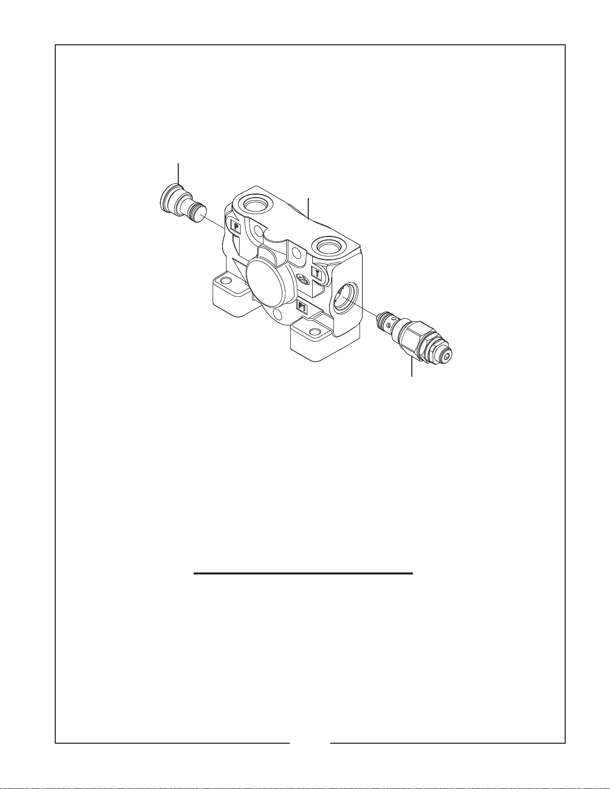
50033297 INLET SECTION
For Control Valve 50032997 (BH650 & BH750)
and Control Valve 50102278 (BH850& BH950)
REF. PART
NO NO
1 50033320 1 Main Relief Valve
2 50033319 1 Inlet Cover
3 50033321 1 Plug
50033298 1 Seal Kit
–––– 1 Parbak
–––– 2 O-Ring 12.4 x 1.78 NBR
–––– 2 O-Ring 19.18 x 2.46 NBR
–––– 2 O-Ring 14 x 1.78 NBR
–––– 1 BKC 2050 Ring
QTY. DESCRIPTION
1
14-9-2
Page 25
BUSH HOG / MATERIAL HANDLING REPAIR PARTS MANUAL
SEPTEMBER, 2003
13
14
15
10
9
8
7
12
6
11
5
8
9
4
3
1
2
2
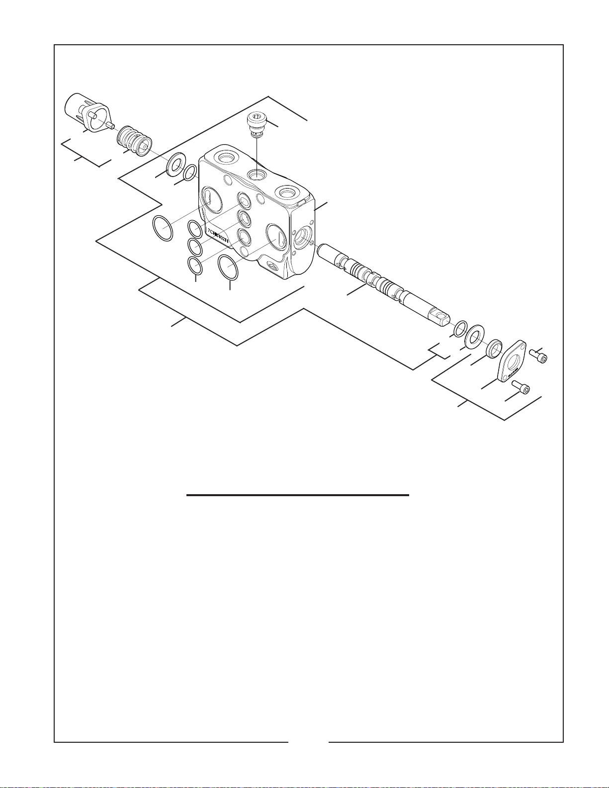
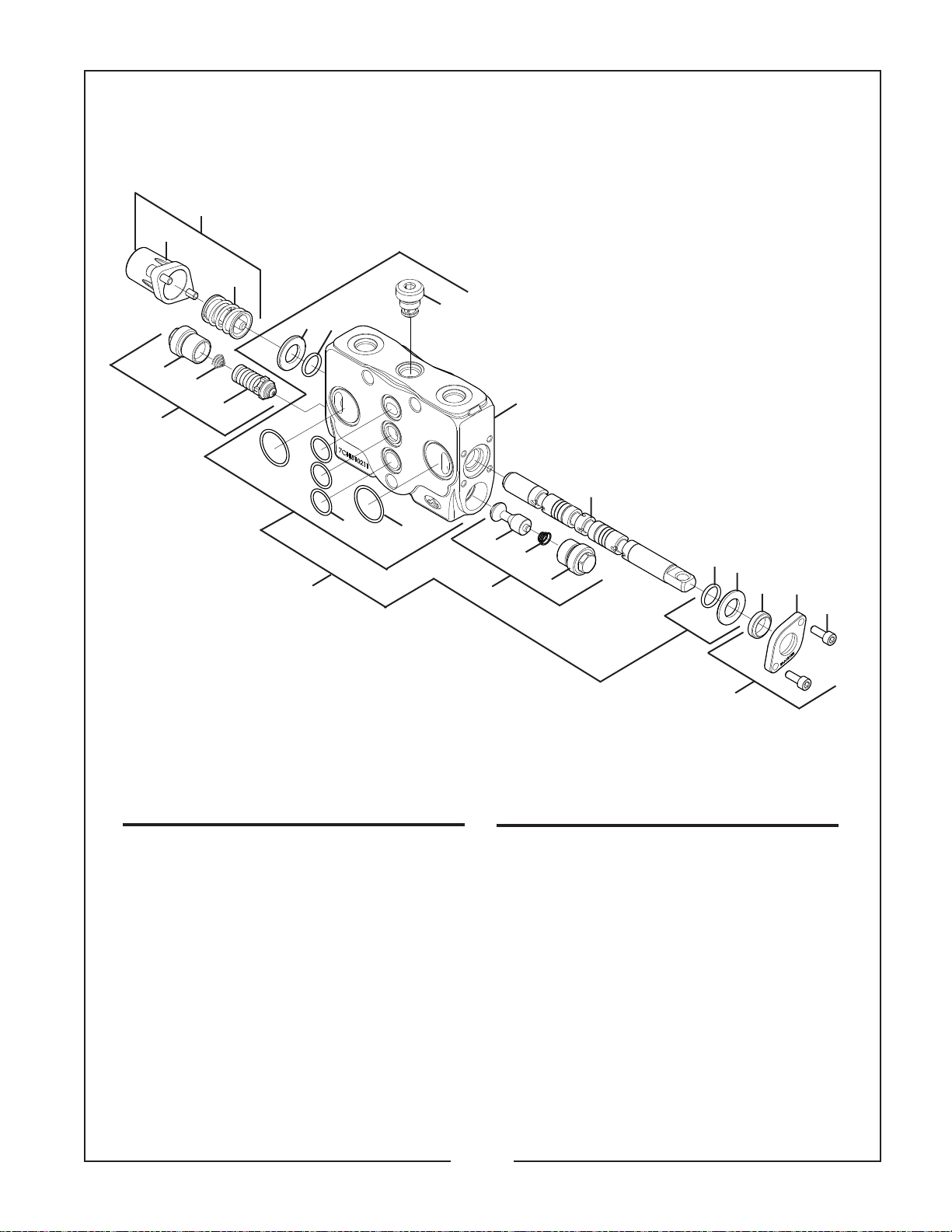
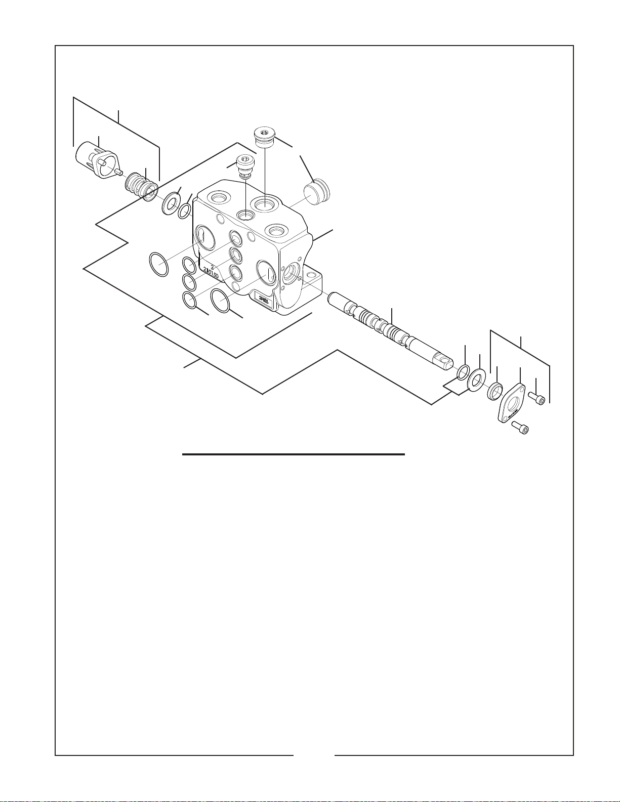
50033293 BUCKET SECTION
For Control Valve 50032997 (BH650 & BH750)
and Control Valve 50102278 (BH850& BH950)
REF. PART
NO. NO.
1 50033306 1 Upper Dust Cap, Valve
2 –––– 2 Screw, M5 x 14 - 8.8
3 –––– 1 Flange
4 –––– 1 Dust Cover
5 50033310 1 Spool
6 50033316 1 Working Section Assembly
7 –––– 1 Working Section
8 –––– 2 O-Ring Seal 14 x 2 NBR 70 SH
9 –––– 2 Seal 14 x 25.5 x 2.3
10 –––– 1 VR Kit
11 –––– 2 O-Ring Seal 26.7 x 1.78 NBR
12 –––– 3 O-Ring Seal 17.7 x 1.78 NBR
13 50033309 1 Spool Control Kit
14 –––– 1 End Cap Kit
15 –––– 1 Spool Control Kit
16 50033299 1 Seal Kit
–––– 1 O-Ring Seal 11.3 x 2.4 NBR
–––– 2 O-Ring Seal 14 x 2 NBR 70 SH
–––– 3 O-Ring Seal 17.17 x 1.78 NBR
–––– 2 O-Ring Seal 26.7 x 1.78 NBR
–––– 1 Dust Cover 14 x 3.5
QTY. DESCRIPTION
14-9-3
Page 26
BUSH HOG / MATERIAL HANDLING REPAIR PARTS MANUAL
SEPTEMBER, 2003
19
18
20
21
22
23
8
7
5
6
14
10
13
11
17
15
16
12
24
27
26
25
9
13
14
4
3
2
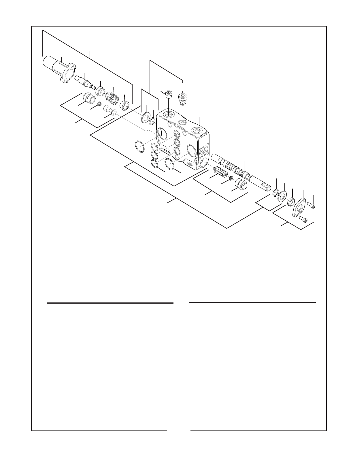
50033295 BOOM SECTION
For Control Valve 50032997 (BH650 & BH750)
50102832 BOOM SECTION
for Control Valve 50102278 (BH850 & BH950)
REF. PART
NO. NO.
1 50033306 1 Upper Dust Cap
2 –––– 2 Screw M5 x 14 – 8.8
3 –––– 1 Flange
4 –––– 1 Dust Cover 14 x 3.5
5 50033313 1 Shutter Assembly
6 –––– 1 Shutter
7 –––– 1 Valve Spring
8 –––– 1 Valve Plug
9 50033317 1 Spool
10 50033315 1 Orifice 2mm (BH650, BH750)
50102835 1 Orifice 2.4mm (BH850, BH950)
11 50033318 1 Working Section Assembly
12 –––– 1 Working Section SAE 6
13 –––– 2 O-Ring 14 x 2 NBR 70SH
14 –––– 2 Seal 14 x 25.5 x 2.3
15 –––– 1 VR Kit
16 –––– 2 O-Ring 26.7 x 1.78 NBR
17 –––– 3 O-Ring 17.17 x 1.78 NBR
QTY. DESCRIPTION
1
REF. PART
NO. NO.
18 50033312 1 Float Kit
19 –––– 1 End Cap Kit
20 –––– 1 Position Pin
21 –––– 1 Bushing
22 –––– 1 Spring
23 –––– 1 Bushing
24 50033314 1 Work Port
25 –––– 1 Valve Plug
26 –––– 1 Valve Spring
27 –––– 1 Relief Valve 175 BAR
50033300 1 Seal Kit
–––– 1 O-Ring 11.3 x 2.4 NBR
–––– 2 O-Ring 14 x 2 NBR 70SH
–––– 3 O-Ring 17.17 x 1.78 NBR
–––– 2 O-Ring 26.7 x 1.78 NBR
–––– 2 O-Ring 15.6 x 1.78 NBR
–––– 1 Dust Cover 14 x 3.5
QTY. DESCRIPTION
14-9-4
Page 27
BUSH HOG / MATERIAL HANDLING REPAIR PARTS MANUAL
14
15
SEPTEMBER, 2003
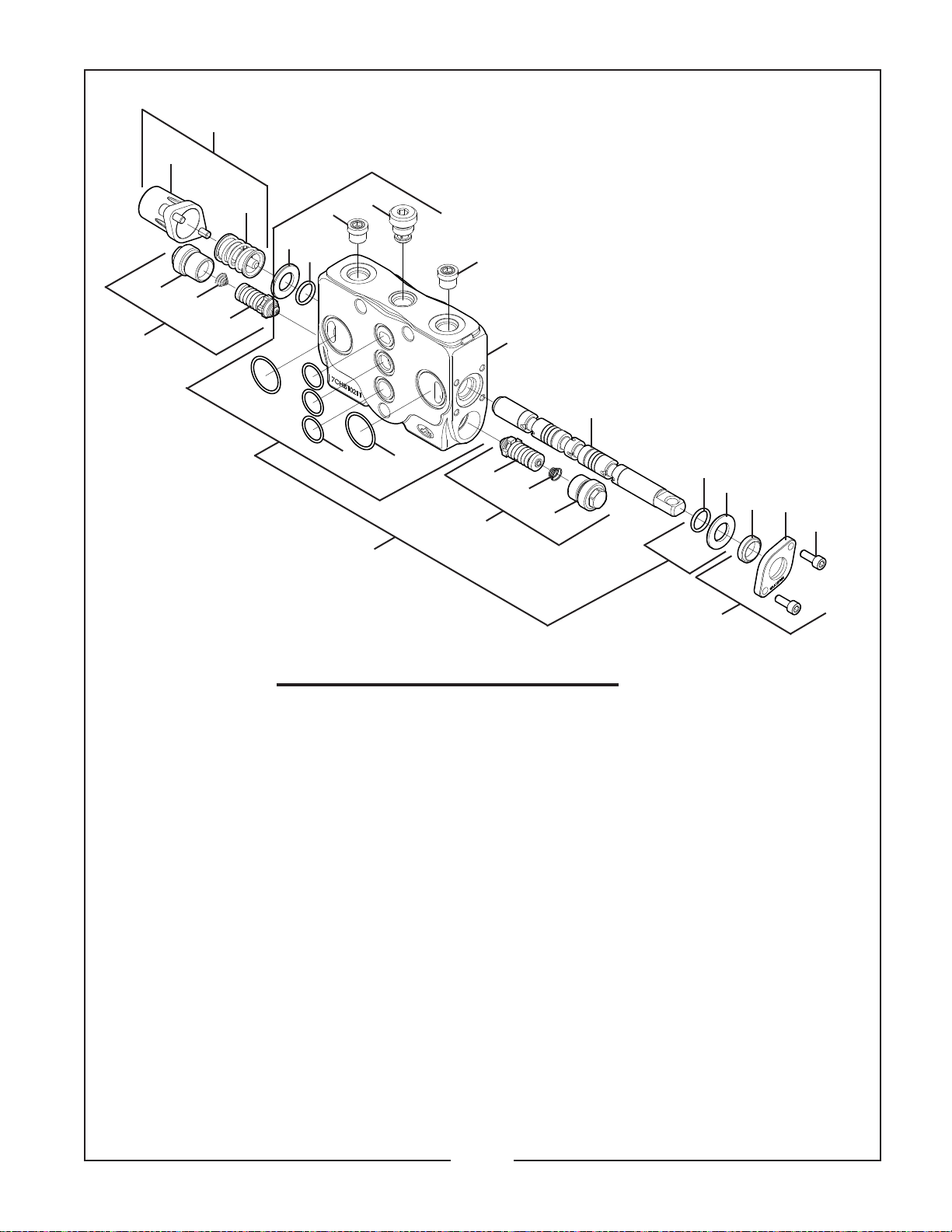
50033294 SWING SECTION
For Control Valve 50032997 (BH650, BH750)
17
18
19
20
16
10
11
6
50102833 SWING SECTION
For Control Valve 50102278 (BH850 & BH950)
9
13
12
7
17
20
6
8
5
9
19
18
10
4
3
2
1
REF. PART
NO. NO.
1 50033306 1 Upper Dust Cap Assembly
2 –––– 2 Screw M5 x 14 – 8.8
3 –––– 1 Flange
4 –––– 1 Dust Cover
5 50033310 1 Spool
6 50033315 2 Orifice 2mm (BH850, BH950)
7 50033311 1 Working Section Assembly
8 –––– 1 Working Section SAE 67
9 –––– 2 O-Ring 14 x 2 NBR 70 SH
10 –––– 2 Seal 14 x 25.5 x 2.3
11 –––– 1 VR Kit
12 –––– 2 O-Ring 26.7 x 1.78 NBR
13 –––– 3 O-Ring 17.7 x 1.78 NBR
14 50033309 1 Spool Control Kit
15 –––– 1 End Cap Kit
16 –––– 1 Spool Control Kit
17 50033314 2 Work Port Relief Assembly
18 –––– 2 Valve Plug
19 –––– 2 Valve Spring
20 –––– 3 Relief Valve 175 BAR
50033301 1 Seal Kit
–––– 1 O-Ring 11.3 x 2.4 NBR
–––– 2 O-Ring 14.2 x 70SH
–––– 3 O-Ring 17.7 x 1.78 NBR
–––– 2 O-Ring 26.7 x 1.78 NBR
–––– 2 O-Ring 15.6 x 1.78 NBR
–––– 1 Dust Cover 14 x 3.5
QTY. DESCRIPTION
14-9-5
Page 28
BUSH HOG / MATERIAL HANDLING REPAIR PARTS MANUAL
50033292 DIPPER STICK SECTION
For Control Valve 50032997 (BH650 & BH750)
and Control Valve 50102278 (BH850 & BH950)
17
18
19
SEPTEMBER, 2003
20
21
22
23
10
13
12
16
15
14
11
9
6
7
5
8
12
13
4
3
2
1
REF. PART
NO. NO.
1 50033306 1 Upper Dust Cap
2 –––– 2 Screw M5 x 14 - 8.8
3 –––– 1 Flange
4 –––– 1 Dust Cover
5 50033313 1 Shutter Assembly
6 –––– 1 Shutter
7 –––– 1 Valve Spring
8 –––– 1 Valve Plug
9 50033310 1 Spool
10 50033311 1 Working Section Assembly
11 –––– 1 Working Section (SAE 6)
12 –––– 2 O-Ring 14 x 2 NBR 70SH
13 –––– 2 Seal 14 x 25.5 x 2.3
14 –––– 1 VR Kit
15 –––– 2 O-Ring 26.7 x 1.78 NBR
16 –––– 3 O-Ring 17.17 x 1.78 NBR
QTY. DESCRIPTION
REF. PART
NO. NO.
17 50033309 1 Spool Control Kit
18 –––– 1 End Cap Kit
19 –––– 1 Spool Control Kit
20 50033314 1 Work Port Relief
21 –––– 1 Valve Plug
22 –––– 1 Valve Spring
23 –––– 1 Relief Valve 175 BAR
50033303 1 Seal Kit
–––– 1 O-Ring 11.3 x 2 NBR
–––– 2 O-Ring 14 x 2 NBR 70 SH
–––– 3 O-Ring 17.17 x 1.78 NBR
–––– 2 O-Ring 26.7 x 1.78 NBR
–––– 2 O-Ring 15.6 x 1.78 NBR
–––– 1 Dust Cover 14 x 3.5
14-9-6
QTY. DESCRIPTION
Page 29
BUSH HOG / MATERIAL HANDLING REPAIR PARTS MANUAL
14
15
16
10
11
9
SEPTEMBER, 2003
50033291 R.H. STABILIZER SECTION
For Control Valve 50032997 (BH650 & BH750)
and Control Valve 50102278 (BH850 & BH950)
6
8
5
13
7
REF. PART
NO. NO.
1 50033306 1 Upper Dust Cap
2 –––– 2 Screw, M5 x 14 – 8.8
3 –––– 1 Flange
4 –––– 1 Dust Cover 14 x 3.5
5 50033310 1 Spool
6 25H50798 2 Valve Plug (SAE 10)
7 50033307 1 R.H. Stabilizer Working Section
8 –––– 1 Working Section
9 –––– 2 O-Ring 14 x 2 NBR 70 SH
10 –––– 2 Seal 14 x 25.5 x 2.3
11 –––– 1 VR Kit
12 –––– 2 O-Ring 26.7 x 1.78 NBR
13 –––– 3 O-Ring 17.17 x 1.78 NBR
14 50033309 1 Spool Control Kit
15 –––– 1 End Cap Kit
16 –––– 1 Spool Control Kit
12
QTY. DESCRIPTION
50033302 1 Seal Kit
–––– 1 O-Ring 11.3 x 2.4 NBR
–––– 2 O-Ring 14 x 2 NBR
–––– 3 O-Ring 17.17 x 1.78 NBR
–––– 2 O-Ring 26.7 x 1.78 NBR
–––– 2 O-Ring 19.18 x 2.46 NBR
–––– 1 Dust Cover 14 x 3.5
9
10
1
4
3
2
14-9-7
Page 30

Page 31

BUSH HOG / MATERIAL HANDLING REPAIR PARTS MANUAL
50033513 DIPPER STICK CYLINDER
SEPTEMBER, 2003
For Model BH650
9
10
2
REF. PART
NO. NO.
1 50028064 2 Shipping Plug
2 50029363 1 Nut
3 50033351 1 Head
4 50033350 1 Retainer Nut
5 50028063 1 Lube Fitting
6 50029364 1 Retaining Ring
7 50033348 1 Rod Assembly
8 50033367 1 Tube Assembly
9 50033361 1 Lube Fitting
QTY. DESCRIPTION
8
1
7
15
REF. PART
NO. NO.
50033344 1 Seal Kit (10–14)
10 –––– 1 Piston Assembly
11 –––– 1 O-Ring
12 –––– 1 Back-Up
13 –––– 1 Wiper
14 –––– 1 U-Cup
15 50100238 1 Decal, Caution
11
12
6
13
3
14
4
QTY. DESCRIPTION
5
50033514 BUCKET CYLINDER
1
5
2
9
REF. PART
NO. NO.
1 50028064 2 Shipping Plug
2 50029363 1 Nut
3 50033351 1 Head
4 50033350 1 Retainer Nut
5 50028063 2 Lube Fitting
6 50029364 1 Retaining Ring
7 50033354 1 Rod Assembly
8 50033353 1 Tube Assembly
QTY. DESCRIPTION
7
For Model BH650
REF. PART
NO. NO.
9 –––– 1 Piston Assembly
10 –––– 1 O-Ring
11 –––– 1 Back-Up
12 –––– 1 Wiper
13 –––– 1 U-Cup
14 50100238 1 Decal, Caution
11
8
14
50033344 1 Seal Kit (9–13)
10
QTY. DESCRIPTION
6
12
13
4
3
5
14-10-1
Page 32

BUSH HOG / MATERIAL HANDLING REPAIR PARTS MANUAL
50033512 SWING CYLINDER
SEPTEMBER, 2003
For Model BH650, BH750
10
9
2
REF. PART
NO. NO.
1 50028064 3 Shipping Plug
2 50032490 1 Nut
3 50033360 1 Head
4 50020734 2 Set Screw
5 50028063 1 Lube Fitting
6 50032489 1 Retaining Ring
7 50033359 1 Rod Assembly
8 50033358 1 Tube Assembly
9 50033361 1 Lube Fitting
QTY. DESCRIPTION
7
11
8
REF. PART
NO. NO.
50033345 1 Seal Kit (10–14)
10 –––– 1 Piston Assembly
11 –––– 1 O-Ring
12 –––– 1 Back-Up
13 –––– 1 Wiper
14 –––– 1 U-Cup
15 50100238 1 Decal, Caution
3
15
1
QTY. DESCRIPTION
12
6
5
4
13
14
50033515 BOOM CYLINDER
9
8
7
5
REF. PART
NO. NO.
1 50028064 2 Shipping Plug
2 50029363 1 Nut
3 50033351 1 Head
4 50033350 1 Retainer Nut
5 50028063 2 Lube Fitting
6 50029364 1 Retaining Ring
7 50033348 1 Rod Assembly
8 50033347 1 Tube Assembly
2
QTY. DESCRIPTION
For Model BH650
REF. PART
1
14
NO. NO.
50033344 1 Seal Kit (9–13)
9 –––– 1 Piston Assembly
10 –––– 1 O-Ring
11 –––– 1 Back-Up
12 –––– 1 Wiper
13 –––– 1 U-Cup
14 50100238 1 Decal, Caution
11
10
3
6
12
13
4
QTY. DESCRIPTION
5
14-10-2
Page 33

BUSH HOG / MATERIAL HANDLING REPAIR PARTS MANUAL
50033324 STABILIZER CYLINDER
5
7
For Model BH650, BH750
8
SEPTEMBER, 2003
1
10
6
11
5
2
9
REF. PART
NO. NO.
1 50028064 2 Shipping Plug
2 50029363 1 Nut
3 50033357 1 Head
4 50020734 2 Set Screw
5 50028063 2 Lube Fitting
6 50029364 1 Retaining Ring
7 50033356 1 Rod Assembly
8 50033355 1 Tube Assembly
QTY. DESCRIPTION
50033528 BOOM CYLINDER
9
8
15
14
REF. PART
NO. NO.
9 –––– 1 Piston Assembly
10 –––– 1 O-Ring
11 –––– 1 Back-Up
12 –––– 1 Wiper
13 –––– 1 U-Cup
14 50102298 1 Decal, Important
15 50100238 1 Decal, Caution
For Model BH750
7
1
12
34
QTY. DESCRIPTION
50033346 1 Seal Kit (9–13)
10 11
6
13
12
5
2
5
REF. PART
NO. NO.
1 50028064 2 Shipping Plug
2 50028055 1 Nut
3 50033545 1 Head
4 50026167 1 Retainer Nut
5 50028063 2 Lube Fitting
6 50028062 1 Retaining Ring
7 50033547 1 Rod Assembly
8 50033546 1 Tube Assembly
QTY. DESCRIPTION
14
REF. PART
NO. NO.
50033544 1 Seal Kit (9–13)
9 –––– 1 Piston Assembly
10 –––– 1 O-Ring
11 –––– 1 Back-Up
12 –––– 1 Wiper
13 –––– 1 U-Cup
14 50100238 1 Caution Decal
14-10-3
13
3
4
QTY. DESCRIPTION
Page 34

BUSH HOG / MATERIAL HANDLING REPAIR PARTS MANUAL
50033529 DIPPERSTICK CYLINDER
SEPTEMBER, 2003
For Model BH750
5
REF. PART
NO. NO.
1 50028064 2 Shipping Plug
2 50028055 1 Nut
3 50033545 1 Head
4 50026167 1 Retainer Nut
5 50028063 2 Lube Fitting
6 50028062 1 Retaining Ring
7 50033549 1 Rod Assembly
8 50033548 1 Tube Assembly
9
2
QTY. DESCRIPTION
8
7
REF. PART
1
14
NO. NO.
9 –––– 1 Piston Assembly
10 –––– 1 O-Ring
11 –––– 1 Back-Up
12 –––– 1 Wiper
13 –––– 1 U-Cup
14 50100238 1 Caution Decal
10 11
3
50033544 1 Seal Kit (9–13)
6
12
13
4
QTY. DESCRIPTION
5
50033530 BUCKET CYLINDER
1
5
9
REF. PART
NO. NO.
1 50028064 2 Shipping Plug
2 50029363 1 Nut
3 50033551 1 Head
4 50102555 1 Retainer Nut
5 50028063 2 Lube Fitting
6 50030239 1 Retaining Ring
7 50033553 1 Rod Assembly
8 50033552 1 Tube Assembly
QTY. DESCRIPTION
For Model BH750
7
8
14 13
REF. PART
NO. NO.
50033550 1 Seal Kit (9–13)
9 –––– 1 Piston Assembly
10 –––– 1 O-Ring
11 –––– 1 Back-Up
12 –––– 1 Wiper
13 –––– 1 U-Cup
14 50100238 1 Caution Decal
10 11
32
6
4
QTY. DESCRIPTION
5
12
14-10-4
Page 35

BUSH HOG / MATERIAL HANDLING REPAIR PARTS MANUAL
50033482 SWING CYLINDER
November, 2004
For Model BH850 & BH950
2
3
REF. PART
NO. NO.
1 50028064 2 Shipping Plug
2 50033361 1 Lube Fitting
3 50029363 1 Nut
3 50102556 1 Head
4 50102555 1 Retainer Nut
6 50028063 1 Lube Fitting
7 50030239 1 Retaining Ring
8 50102554 1 Rod Assembly
9 50102553 1 Tube Assembly
QTY. DESCRIPTION
14
9
REF. PART
NO. NO.
10 –––– 1 U-Cup
11 –––– 1 Wiper
12 –––– 1 Back Up
13 –––– 1 O-Ring
14 –––– 1 Piston Assembly
15 50100238 1 Caution Decal
1
8
15
50102559 1 Seal Kit (10–14)
4
12
7
13
10
5
QTY. DESCRIPTION
6
11
50033475 STABILIZER CYLINDER
7
2
REF. PART
NO. NO.
1 50028064 2 Shipping Plug
2 50234129 1 Nut
3 50102562 1 Head
4 50020655 1 Retaining Ring
5 50102561 1 Rod Assembly
6 50102560 1 Tube Assembly
7 50028063 1 Lube Fitting
QTY. DESCRIPTION
13
For Model BH850
14
6
1
5
15
REF. PART
NO. NO.
50102564 1 Seal Kit (7–12)
8 –––– 1 U-Cup
9 –––– 2 Set Screw
10 –––– 1 Wiper
11 –––– 1 Back-up
12 –––– 1 O-Ring
13 –––– 1 Piston
14 50102298 1 Decal, Important
15 50100238 1 Decal, Caution
12
11
4
10
983
QTY. DESCRIPTION
14-10-5
Page 36

BUSH HOG / MATERIAL HANDLING REPAIR PARTS MANUAL
50033483 DIPPER / LIFT CYLINDER
SEPTEMBER, 2003
For Model BH850
9
3
REF. PART
NO. NO.
1 50102571 2 Shipping Plug
2 50028063 1 Lube Fitting
3 12293 1 Nut
4 50102570 1 Head
5 50102569 1 Retainer Nut
6 50028070 1 Retaining Ring
7 50102567 1 Rod Assembly
8 50102566 1 Tube Assembly
9 50102565 1 Lube Fitting
QTY. DESCRIPTION
14
1
8
7
15
REF. PART
NO. NO.
10 –––– 1 U-Cup
11 –––– 1 Wiper
12 –––– 1 Back-up
13 –––– 1 O-Ring
14 –––– 1 Piston Assembly
15 50100238 1 Decal, Caution
4
50102572 1 Seal Kit (10–14)
13
12
6
11
10
5
QTY. DESCRIPTION
2
50033484 BUCKET CYLINDER
8
2
REF. PART
NO. NO.
1 50102571 2 Shipping Plug
2 12293 1 Nut
3 50102575 1 Head
4 50026167 1 Retainer Nut
5 50028062 1 Retaining Ring
6 50102574 1 Rod Assembly
7 50102573 1 Tube Assembly
8 50028063 2 Lube Fitting
QTY. DESCRIPTION
13
For Model BH850
7
6
14
REF. PART
NO. NO.
9 –––– 1 U-Cup
10 –––– 1 Wiper
11 –––– 1 Back-up
12 –––– 1 O-Ring
13 –––– 1 Piston Assembly
14 50100238 1 Decal, Caution
1
3
50102576 1 Seal Kit (9-13)
11
12
5
9
4
QTY. DESCRIPTION
10
14-10-6
Page 37

BUSH HOG / MATERIAL HANDLING REPAIR PARTS MANUAL
50033495 DIPPER / LIFT CYLINDER
SEPTEMBER, 2003
For Model BH950
2
3
REF. PART
NO. NO.
1 50102571 2 Shipping Plug
2 50102565 1 Lube Fitting
3 12293 1 Nut
4 50102580 1 Head
5 50020654 1 Retainer Nut
6 50028063 1 Lube Fitting
7 50020655 1 Retaining Ring
8 50102578 1 Rod Assembly
9 50102577 1 Tube Assembly
QTY. DESCRIPTION
14
1
9
8
15
REF. PART
NO. NO.
10 –––– 1 U-Cup
11 –––– 1 Wiper
12 –––– 1 Back-up
13 –––– 1 O-Ring
14 –––– 1 Piston Assembly
15 50100238 1 Decal, Caution
4
50102581 1 Seal Kit (10–14)
13
12
7
11
10
5
QTY. DESCRIPTION
6
50033496 BUCKET CYLINDER
8
2
REF. PART
NO. NO.
1 50102571 2 Shipping Plug
2 12293 1 Nut
3 50102575 1 Head
4 50026167 1 Retainer Nut
5 50028062 1 Retaining Ring
6 50102583 1 Rod Assembly
7 50102582 1 Tube Assembly
8 50028063 2 Lube Fitting
QTY. DESCRIPTION
13
For Model BH950
7
6
14
REF. PART
NO. NO.
9 –––– 1 U-Cup
10 –––– 1 Wiper
11 –––– 1 Back-up
12 –––– 1 O-Ring
13 –––– 1 Piston Assembly
14 50100238 1 Decal, Caution
1
3
50102576 1 Seal Kit (9-13)
11
12
5
9
4
QTY. DESCRIPTION
10
14-10-7
Page 38

Page 39

BUSH HOG / MATERIAL HANDLING REPAIR PARTS MANUAL
November, 2004
31
26
34
22
20
1, 6, 4
2
5
24
23
33
17
18
16
2
7
5
27
15
28
21
7
10
31
26
19
11
8
29
3
14
9
30
12
9
13
REF. PART
NO. NO.
1 ––– 2 Capscrew 1/4” x 3/4” G5
2 –––– 4 Capscrew 3/8” x 1”
3 –––– 2 Capscrew 1/2” x 1-1/2”
4 –––– 2 Flatwasher 1/4”
5 –––– 4 Flatwasher 3/8”
6 –––– 2 Lockwasher 1/4”
7 –––– 4 Lockwasher 3/8”
8 –––– 2 Lockwasher 1/2”
9 –––– 2 Hex Nut 5/16”
10 –––– 4 Hex Nut 3/8”
11 –––– 2 Hex Nut 1/2”
12 50018489 1 Hydraulic Pump, 6 GPM
50032933 1 Hydraulic Pump, 8 GPM
13 50033250 1 PTO Adapter
14 44900 2 Set Screw 5/16” x 3/4”
15 50032930 1 Filter Base & Element
16 50032752 1 Hydraulic Reservoir
17 50033202 1 Fill Tube Assembly
18 50033128 1 Breather Cap w/ Dipstick
19 50033060 1 Suction Hose 1” ID x 30” Long
14
QTY. DESCRIPTION
32
20
50033035 PTO PUMP KIT, 6 GPM
25
For BH650 & BH750
50033037 PTO PUMP KIT, 8 GPM
For BH750, BH850 & BH950
REF. PART
NO. NO.
20 50033059 2 Hose Clamp 3/4” to 1-1/2” ID
21 50033061 1 Return Hose 3/4” ID x 24” Long
22 50033062 1 Hose 3/4” – 16 JICF x 36”
23 50028240 1 Hose, 3/4”–16 JICF x 28”
24 50033058 1 90° Adapter, 1” MNPT x 1” Beaded Tube
25 50033064 1 90° Adapter,
26 50033065 2 90° Adapter,
27 50007232 1 90° Male Elbow, 3/4” NPT x 3/4”–16 JIC
28 25H40576 2 90° Adapter 3/4”–16 JICM x F Swivel
29 61471 1 90° Male Adapter,
30 50033278 1 Straight Adapter,
31 50033066 2 Hose Clamp 11/16” to 1-1/4” ID
32 50033248 1 Torque Plate
33 50033187 1 1” NPT 45° Street Elbow
34 50032929 1 Filter Element
QTY. DESCRIPTION
1-5/16” ORBM x 1” Beaded Tube
3/4” MNPT x 3/4” Beaded Tube
1.06”–12 ORB x 3/4”–16 JIC
1-5/8” ORBM x 1-5/16” ORBF
14-11-1
Page 40

BUSH HOG / MATERIAL HANDLING REPAIR PARTS MANUAL
50018489 HYDRAULIC PUMP, 6 GPM
For Models BH650 & BH750 using the 50033373 PTO Pump Kit, 6 GPM
50032933 HYDRAULIC PUMP, 8 GPM
For Models BH750, BH850 & BH950 using the 50033434 PTO Pump Kit, 8 GPM
SEPTEMBER, 2003
13
8
9
15
4
1
11
2
6
5
3
7
REF. PART
NO. NO.
1 ** 1 Frontplate Assembly
2 ** 1 Backplate Assembly
3 ** 1 Body Assembly
4 ** 1 Drive Gear Assembly 7/8” Straight Extended Keyed Shaft
5 ** 1 Idler Gear Assembly
6 * 1 Wear Plate
7 * 2 O-Ring
8 * 1 Shaft Seal
9 * 1 Washer
10 * 1 Bearing Seal
11 * 1 Molded O-Ring
12 * 1 Backup Gasket
13 ** 4 Cap Screw
14 ** 4 Cap Screw
15 ** 1 Key
16 50033608 1 Seal Kit
QTY. DESCRIPTION
10
12
7
14
*Not sold separately; order seal kit.
**Not sold separately; order complete pump.
14-11-2
Page 41

BUSH HOG / MATERIAL HANDLING REPAIR PARTS MANUAL
Remove Port “C” plug and install
power beyond plug inside port.
1
2
SEPTEMBER, 2003
Backhoe valve
Hose supplied by customer
To pressure port of
accessory control valve
50033038 POWER BEYOND KIT
For BH650, BH750, BH850, BH950
REF. PART
NO. NO.
1 50033045 1 Power Beyond / Closed Center Plug
2 25H40475 1 90° Male Adapter 7/8”–14 ORB x 3/4”–16 JIC
3 50033229 1 Instruction Sheet
QTY. DESCRIPTION
3
14-11-3
Page 42

BUSH HOG / MATERIAL HANDLING REPAIR PARTS MANUAL
Pressure line
from Skid Steer
1
To Backhoe Bulkhead
“Pressure” connection
10
10
SEPTEMBER, 2003
3
FLOW DIVIDER VALVE
TO BACKHOE MOUNTING
5
9
8
Return Line
to Skid Steer
To Backhoe Bulkhead
“Tank” connection
7
Return Line
to Skid Steer
11
8
6
7
11
7
To Backhoe Bulkhead
“Tank” connection
To Backhoe Bulkhead
“Pressure” connection
7
1
Pressure line
from Skid Steer
10
FLOW DIVIDER VALVE TO SKID
STEER ADAPTER MOUNTING
50033040 FLOW DIVIDER KIT
For Models BH650, BH750, BH850, BH950
REF. PART
NO. NO.
1 –––– 3 Capscrew 5/16” x 2-1/2”
*2 –––– 2 Capscrew 5/8” x 1”
3 15602 3 Locknut 5/16”
*4 –––– 2 Lockwasher 5/8”
5 50033069 1 Flow Divider Valve
*6 50033554 1 Male Adapter 1.06”–12 ORB x 7/8”–14 JIC
7 25H45930 2 45° Adapter, 3/4”–16 JIC M x F Swivel
8 25H51635 1 90° Adapter, 7/8”–14 JIC M x F Swivel
9 50033071 1 Swivel Run Tee, 7/8”–14 JIC M x M x F Swivel
10 50033072 3 90° Male Adapter, 1.06”–12 ORB x 7/8”–14 JIC
11 50033073 2 Hydraulic Hose, 3/4”–16 x 7/8”–14 JIC F Swivel x 24”
*12 50102917 1 Valve Mount Plate
QTY. DESCRIPTION
9
10
5
3
12
4
2
*Ref. #2, 4, 6, 12 are used only when mounting Flow Divider valve to Skid Steer adaptor.
14-11-4
Page 43

BUSH HOG / MATERIAL HANDLING REPAIR PARTS MANUAL
SEPTEMBER, 2003
Remove port “C” plug and install
closed center plug inside port.
Re-install Port “C” plug.
BACKHOE VALVE
1
2
TANK
PRESSURE
TO TRACTOR
RESERVOIR
BACKHOE BULKHEAD
CONNECTORS
7
HOSES SUPPLIED
BY CUSTOMER
4
6
5
9
6
TRACTOR
COUPLER TIPS
8
3
5
50033039 CLOSED CENTER KIT
For BH750, BH850, BH950
REF. PART
NO. NO.
1 50033045 1 Power Beyond / Closed Center Plug
2 50033046 1 Relief Valve Cartridge
3 50033050 1 Restrictor, 1/2” M NPT x 1/2” F NPT, .095 Orifice
4 25H42789 1 Hydraulic Hose, 3/4”–16 JIC F Swivel Ends x 24”
5 25H48499 2 Pipe Nipple, 1/2” NPT Close
6 25D25683 2 Male Adapter, 1/2” NPT x 3/4”–16 JIC
7 97343 1 Male Adapter, 3/8” NPT x 3/4”–16 JIC
8 50033225 1 Adaptor, 1/2” F NPT x 3/4”–16 M JIC
9 50033053 1 Relief Valve
QTY. DESCRIPTION
14-11-5
Page 44

Page 45

BUSH HOG / MATERIAL HANDLING REPAIR PARTS MANUAL
IMPORTANT
IMPROPER HYDRAULIC HOOK-
UP CAN CAUSE SERIOUS
DAMAGE TO VALVE
•
REFER TO ATTACHING KIT OR
PTO PUMP KIT MANUAL FOR
PROPER HYDRAULIC HOOK-UP.
•
NEVER PRESSURIZE RETURN
PORT OF VALVE OR RESTRICT
RETURN HOSE.
•
ALWAYS MOVE TRACTOR
3-POINT HITCH CONTROL TO
FULLY LOWERED POSTION
WHILE BACKHOE IS
MOUNTED TO TRACTOR.
50102296
To avoid serious injury or death:
Do not operate this backhoe unless
it is rigidly attached to the tactor using
the appropriate factory - provided
mounting kit. Do not mount backhoe
on a 3-point "Quick Attaching Coupler".
50102293
CRUSHING HAZARD
DANGER
DO NOT OPERATE 3 POINT RIGID MOUNT
BACKHOE UNLESS HITCH AND STAB LIZER
BARS ARE INSTALLED PROPERLY. FAILURE TO
DO SO MAY RESULT IN SERIOUS INJURY OR
DEATH FROM BACKHOE BE NG THRUST
UPWARD BY DIGGING FORCES CRUSHING
OPERATOR.
OPERATOR S AREA (SHADED AREA OF 40"
RAD US FROM SEAT TO 10" BEHIND SEAT)
MUST BE FREE FROM ALL OBSTRUCTIONS.
USE ONLY SPECIAL HITCH PARTS SUPPLIED
WITH BACKHOE. SEE OPERATOR S MANUAL
FOR PROPER ASSEMBLY AND ADJUSTMENT
OF HITCH.
10" MN
40" MIN
RADOUS
TOP LINK
STABILIZER BARS
50102292
50033414 DECAL KIT FOR BH650
50033541 DECAL KIT FOR BH750
50033458 DECAL KIT FOR BH850
50033506 DECAL KIT FOR BH950
OCTOBER, 2003
50102298
50102296
50102293
50102295
50033282
50102297
50102292
50100238
50033366
12115
50033364
50036633
50102294 (BH650)
50033476 (BH750)
50102523 (BH850)
50033477 (BH950)
14-12-1
BH650
50033051
BH750
50033216
BH850
50033426
BH950
50033427
Page 46

Page 47

BUSH HOG / MATERIAL HANDLING REPAIR PARTS MANUAL
CAUTON: e ore e v ng t a to se t st p engne ock ra e e eve h d au c
pr ss re ad emo e key
CAUTON: o ot aow by t nd rs n work r a
NS ALLATON NOTES
• Remve l mon ng b a kt f om rte Re e t F g 1 n P ge 2 o nu e t a a l omp n n s h ve een cued)
• Clan h e ded o es n he r c or r me w th t p of he r pe s ze Pa nt u t a d/ r d bis
in he he ds m y ca se ots o msa gn r n t t g tn c r e ty
• Ths m un ng t hs b th an ad a d me i f se e s nu e ha t e po er s en s a e u ed n he o r ct
lc t o s ( e er o Fg 2 on a e 2 as n ad o i e t yn co e t as nes)
• Leve l mou tng a dw re o se u tl out ng i is om l t ly n a l d
• At r he m un ng t n t l t o is om ee gt n a l adw e to h sp c i ao s g v n n t e b l t r ue h rt
onP ge 6
• At r he r t h u and en ae ev r 4 ho r f r he r t d y o o ea i n al mo n ng adw re h ud be h ck d
fr p o er r ue pe fc ins
age 1
101 04
0203
nt u i n Sh e No 50 4 940
F R RACTOR MODE S
JOHN DEERE®770 90
FORMOUNT NG
Bush Hog 650 / 750 BackHoe
Gr at Bend 2 65 / 175 B ckHoe
BUSH HOG / GREAT BEND
SUBFRAME ATTACHNG KIT 500415 4
U i g Bush Hg M 46 L ad r Gr at B nd 2 25 Lo der
50045936 SUBFRAME KIT
For Bush Hog Backhoe Models BH650, BH750
Used on Ford/New Holland TC35, TC35A, TC35D, TC35DA, TC40, TC40A,TC40D,
TC40DA, TC45, TC45A, TC45D & TC45DA Tractors
and Case/IH D35, DX35, D40, DX40, D45 & DX45 Tractors
with Bush Hog 2346 QT Loader or Great Bend 284 Loader.
11
7
25
26
21
19
JUNE, 2008
24
3
22
11
8
Bush Hog
4
16
Loader Mount
10
17
REF. PART
NO. NO. QTY. DESCRIPTION
1 45017 4 Capscrew 1/2” NF x 3-1/2” Gr.5 ZP NF
2 15032 6 Capscrew 5/8” NF x 2” Gr.5 ZP
3 15046 2 Capscrew 7/8” NF x 2” Gr.5
4 –––– 2 Capscrew 7/8” NC x 2-1/2” Gr.5 ZP
5 20964 4 Locknut 1/2” NF CP Center
6 44743 6 Hex Nut 5/8” NF CP
7 44061 2 Hex Nut 7/8” NF CP Class 2B
8 –––– 2 Hex Nut 7/8” CP
9 –––– 6 Lockwasher 5/8” CP
10 50032825 2 3 Point Lower Pin
11 –––– 4 Lockwasher 7/8” CP
12 50020926 8 Fatwasher 1/2” SAE Hardened ZP
13 0461086 2 Hair Pin Clip #6
14 50034866 2 Spacer
15 50034867 2 Front Hanger Weldment
16 50045934 1 R.H. Frame Rail Weldment
17 50045935 1 L.H. Frame Rail Weldment
18 50034870 2 Lock Pin
19 50035322 1 Brace R.H.
20 50034862 1 Cross Support Weldment
21 50005860 2 Cotter, Hair Pin
22 50034865 1 Brace, L.H.
23 50034873 1 Instruction Sheet
24 44896 2 Capscrew 3/4” x 2” NF
25 –––– 2 Lockwasher 3/4”
26 44897 2 Hex Nut 3/4” NF
6
9
12
14
5
12
1
13
20
15
18
2
23
14-13-1
Page 48

BUSH HOG / MATERIAL HANDLING REPAIR PARTS MANUAL
CA TI N: Be oe l av ng r c or s at s op e g ne lo k b ake r l e e hy ra lc
pe su e nd r move ey
CA TI N: Do No al w b s an e s n wo k a ea
INSTALLATION NOTES
• Rmo e a l m u t ng ac es r m ca e (R er o Fg 1 on ag 2 to sue h t a co poe ts a e ben n l d d)
• Ce n t r ad d h l s in he ac o f ame i h a ap o t e pop r s e P i t r st nd o de r s
nt e t r ad may c u e bo s to m ain or ot gh en or c ly
• T s mo ni g kt as oh s ndrd nd m r c a t n rs I s re h t he r p r as ne s re se in h co et
oa ons Re e t Fg on Pge 2 s an id o d n f ng c r ct a en r )
• La e a l mo ni g h r wa e l os un l mo n i g kt s c mpe ey nsa ed
• Aer e mou i g kt s aa on s cmp ee i hen l h rwa e o he s e ic t ns i en n he o t oq e c a t
on ae 6
• Aer e fs ho r a d hen tr e ey 4 h u s or e fs day f pea on ll mu t g had ae s oud e c ec ed
or r p r o q e sp c cao s
Pae 1
0/ 1 04
70 03
Is r c on het No 00 1 40
FOR TRAC OR MODELS
JOHN DEERE®770 790
ORMO NT NG
Bush Hog 50 / 50 Ba kHoe
Great Bend 2165 / 2175 BackHoe
BUSH HOG / GREAT BEND
SUBFRAME ATTACHNG KT 50 41534
Usng Bu h Hog M1 6 Loa er G e t Be d 125 oa er
for Bush Hog Backhoe Models BH650 and BH750
Kubota L2900, L3010, L3300, L3410, L3600, L3710, L4200, L4310
Use with Bush Hog 2246 QT Loader or
JUNE, 2008
50036453 SUBFRAME KIT
used on Tractor Models
Great Bend 244 Loader
11 21
4
25
27
26
5
23
13
22
11
8
3
1
REF. PART
NO. NO.
QTY. DESCRIPTION
1 44893 6 Capscrew 5/8” x 1-1/2” Gr.5 ZP NF
2 44930 6 Capscrew 5/8” x 2-3/4” Gr.5 ZP NF
3 44894 4 Capscrew 3/4” x 1-1/2” Gr.5 ZP NF
4 15046 2 Capscrew 7/8” x 2” Gr.5 ZP NF
5 –––– 2 Capscrew 7/8” x 2” Gr.5 ZP
6 44743 10 Hex Nut 5/8” NF
7 44897 4 Hex Nut 3/4” NF
8 –––– 4 Hex Nut 7/8” CP
9 –––– 10 Lockwasher 5/8” CP
10 –––– 4 Lockwasher 3/4” ZP
11 –––– 6 Lockwasher 7/8” CP
12 0461086 2 Pin Clip #6
13 50034919 2 Brace
14 50034921 2 Shim 1/2”
15 50034920 2 Shim 5/8”
16 50034870 2 Lock Pin
17 50034903 1 R.H. Frame Rail Weldment
18 50034904 1 L.H. Frame Rail Weldment
19 50034907 1 Rear Hanger Weldment
20 50034911 1 Front Mount Weldment
21 44061 2 Hex Nut 7/8” NF
22 20571 2 Flatwasher 7/8”
23 20132 2 Capscrew 7/8” x 3” Gr.5
24 50034923 1 Instruction Sheet
25 44896 2 Capscrew 3/4” x 2” NF
26 –––– 2 Lockwasher 3/4”
27 44897 2 Hex Nut 3/4” NF
10
13
8
11
17
Loader Mount
7
6
19
9
18
20
12
2
14
15
16
9 6
24
14-13-2
Page 49

BUSH HOG / MATERIAL HANDLING REPAIR PARTS MANUAL
C UTON: B fo e ea ing acor eat s op ngne l ck bake ei ve hy r ul c
re su e and emove ey
C UTON: Do N t a l w ys a des in w rk a ea
INSTALLATION NOTES
• Rmo e a l out g b a kes om ca e ( eer o Fg 1 o Pa e 2 t i s re h t l c mpo e t ha e b en n l d d)
• Ce n hr a ed h l s n t e t a t r f a e wi h a ap f he p o er i e P nt rs an /o de rs
n he hr a s may au e bo s o mi a gn or ot gh n co r c y
• h s mo nng k ha bo h t nd d and e rc a t n rs I s re at he op r a t nes re s d i t e c re t
oa ons R f r o F g 2 on P ge 2 s an i to d n f ng or c f s e es)
• ea e a l m un ng h r wae oo e un l mo n i g kt s c mpe ey ns led
• Ae t e mo ni g k i sa a on s c mp te i hen l h r wa e o he pe fa i ns i en n he ot o q e c at
nPa e 6
• Ae t e f s ho r nd h n a tr ve y 4 ous o t e f s d y of p r t n l mou i g h r wae s o ld e c e ked
o p opr oq e s ec c t os
Pge 1
0/ 1 04
72 03
Is uc on he t No 00 1 40
FORTRA TOR MODELS
JOHN DEERE®7 0 790
ORMOUNT NG
Bu h Hog 650 / 750 B ckHoe
Great Bend 2165 / 21 5 BackHoe
BUSH HOG / GREAT BEND
SUBFRAME ATTACHING KT 5 041534
Usng B sh Hog M1 6 Lo der G e t Be d 21 5 Loa er
50036454 SUBFRAME KIT
for Bush Hog Backhoe Models BH650 and BH750
Kubota L3600, L3710, L4200, L4310
Use with Bush Hog 2346 QT Loader
12
28
7
27
11
Used on Tractor Models
or Great Bend 284 Loader
4
3
14
JUNE, 2008
29
14
4
18
12
8
26
2
1
25
REF. PART
NO. NO.
QTY. DESCRIPTION
1 44893 4 Capscrew 5/8” x 1-1/2” Gr.5 ZP NF
2 44894 4 Capscrew 3/4” x 1-1/2” Gr.5 ZP NF
3 15046 2 Capscrew 3/4” x 2” Gr.5 ZP NF
4 20260 2 Capscrew 7/8” x 2” Gr.5 ZP
5 44334 4 Capscrew M12 x 1.25 x 30mm Gr.8.8 ZP
6 44743 10 Hex Nut 5/8” NF
7 44897 4 Hex Nut 3/4” NF
8 19503 4 Hex Nut 7/8” CP
9 –––– 4 Lockwasher 1/2” CP
10 –––– 10 Lockwasher 5/8” CP
11 –––– 4 Lockwasher 3/4” ZP
12 –––– 4 Lockwasher 7/8” CP
13 0461086 2 Hair Pin Clip #6
14 50034919 2 Brace
15 50034870 2 Lock Pin
16 50034903 1 R.H. Frame Rail Weldment
17 50034904 1 L.H. Frame Rail Weldment
18 50034907 1 Rear Hanger Weldment
12 8
16
Tractor
Frame
7
11
6
10
17
19
23
9
5
24
*
20
REF. PART
NO. NO.
QTY. DESCRIPTION
19 25H51894 2 Spacer 2”
20 50034957 4 Shim, 3/16”
21 50034947 1 Support Bracket Weldment
22 50034951 1 Front Mount Weldment
23 –––– 4 Flatwasher 1/2”
24 44821 4 Capscrew M12 x 1.25 x 100 Gr.8.8
25 15032 6 Capscrew 5/8” x 2” Gr.5 ZP NF
26 20571 2 Flatwasher 7/8”
27 20132 2 Capscrew 7/8” x 3” Gr.5 ZP
28 44061 2 Hex Nut 7/8” NF
29 50034959 1 Instruction Sheet
Loader Mount Components
*
13
15
10 6
21
13
15
22
14-13-3
Page 50

BUSH HOG / MATERIAL HANDLING REPAIR PARTS MANUAL
AUTON: B f re ea i g ac or eat top ngne l ck b ake ei ve h dr u ic
r ssu e and emo e ey
AUTON: Do N t a l w ysa de s in w rk a ea
NSTALLATION NOTES
• Rmo e a l out g b a kes om ca e ( eer o ig 1 n Pa e 2 o i s re ht l c mpne t ha e b en n ud d)
• C an h ea ed h l s n t e t a t r r me w th a ap f he p o er i e a nt us an / r dbrs
n he h ea s may au e b l s o mi a gn o no t g t n co ec y
• h s mo nng i h s boh t n ad an mer c a enrs nsr t at e popr a tn rs re s d n t e c r et
oa o s R f r o F g 2 on P ge 2 s an d to en y ng or c f s e es)
• ea e a l m un ng h r wae oo e un l m un ng k t s omp ee y n t led
• fe t e mo n ng i i sa a on s omp te ghe al a dw re o he pe f ains ve in h bot r ue ha t
nPa e 6
• fe t e is h ur nd h n a er ve y 4 o rs o t e i s d y o op r t n l mo ni g h r wa e so l be c e k d
o p o er o q e s ei c to s
Pge 1
0/ 1 04
72 03
nsu t o Sh et o 0 41 40
FOR TR CTOR MODELS
OHN DEERE®7 0 790
FORMOUNT NG
B sh Hog650 / 750 BackHoe
Great Be d 2165 / 21 5 Bac Hoe
BUSH HOG / GREAT BEND
SUBFRAME ATTACHING KT 0041534
Usng B sh Hog M 46 Lo der Gre t Be d 21 5 Loa er
for Bush Hog Backhoe Models BH650 and BH750
Ford/NewHolland 1530, 1630, 1725, 1925, TC25, TC250, TC29, TC290, TC33, TC330
Case/IH D25, DX25, D29, DX29, D33, DX33
With Bush Hog 2246QT Loader or Great Bend 244 Loader
JUNE, 2008
50036455 SUBFRAME KIT
used on Tractor Models
20 24
31
30
23
29
7
20 21
13
4
19
28
11
17
REF. PART
NO. NO.
QTY. DESCRIPTION
1 50035372 1 Front Mount Weldment
2 50035365 1 Rail Weldment R.H.
3 50035366 1 Rail Weldment L.H.
4 50035379 1 Rear Axle Weldment R.H.
5 50035380 1 Rear Axle Weldment L.H.
6 50035355 1 Angle
7 50035356 2 Brace
8 50034870 2 Lock Pin
9 0461086 2 Hair Pin
10 15032 6 Capscrew 5/8” x 2” - NF Gr.5
11 ––––––– 6 Lockwasher 5/8”
12 92500 2 Hex Nut 5/8” - NF
13 20260 2 Capscrew 7/8” x 2” Gr.5
14 ––––––– 2 Lockwasher 7/8”
15 ––––––– 2 Hex Nut 7/8”
16 50035520 1 Instruction Sheet
17 44394 8 Capscrew m12 x 1.75 x 30 Gr 8.8
18 15806 10 Lockwasher 1/2”
19 20132 2 Capscrew 7/8” x 3” Gr.5
20 ––––––– 4 Lockwasher 7/8”
15
14
25
27
5
2
22
6
18
26
3
10
11
REF. PART
NO. NO.
QTY. DESCRIPTION
21 ––––––– 2 Hex Nut 7/8”
22 44895 2 Capscrew m16 x 2 x 30 Gr. 8.8
23 15046 2 Capscrew 7/8” x 2 - NF Gr.5
24 44061 2 Hex Nut 7/8” NF
25 ––––––– 2 Capscrew 1/2” x 1-1/4” Gr.5
26 ––––––– 2 Hex Nut 1/2”
27 ––––––– 2 Flatwasher 1/2”
28 ––––––– 2 Flatwasher 7/8”
29 44896 2 Capscrew 3/4” x 2”
30 –––– 2 Lockwasher 3/4”
31 44897 2 Hex Nut 3/4” NF
16
8
9
1
12
14-13-4
Page 51

BUSH HOG / MATERIAL HANDLING REPAIR PARTS MANUAL
CAUTON: B f re ea i g tac or eat t p ng ne ock b a e ei ve h dr u ic
pr ss re and emo e key
CAUTON: Do N t a ow by ta de s n w rk rea
NSTALLATON NOTES
• emve a mo ni g b a kts om c ae Re e to ig 1 n Pa e 2 o ns re at l c mp n ns h ve b en c ued)
• lan hea ed o es n t e t a t r r me w th a ap f he ro er ze a nt us a d / r d bis
n he h e ds may a se b l s o m sa gn o no tg t n co ec y
• h s m unng i h s bth anad a d me ic sen s n u e t a t e p o er a en rs e usd n t e c re t
cao s R f r o F g 2 on age as a ad t i e t yng o ec f s e es)
• e ve a l ou t ng adwa e oo e u t l m un ng k t s omp e ly nt l d
• fe t e mo n ng i ns laon s om l te gh n al a dw re o he p c i a on g v n in e bo t r ue ha t
n Pge 6
• fe t e i t h ur nd h n a er v ry 4 ors r he i t d y o op r i n l mo n ng h r wae ho d be hek d
o p o er o q e s ei c t ns
Pge 1
101 04
72 03
nt u t n Sh et o 0 41 40
FOR T ACTOR MODE S
OHN DEERE®70 7 0
FOR MOUNTNG
Bush Hog 650 / 750 BackHoe
Gre t B nd 21 5 / 2 75 BakHoe
BUSH HOG / GREAT BEND
SUBFRAME ATTACHING KT 50041534
U i g ush Hog M 46 L ader Gr at B nd 21 5 Lo der
for Bush Hog Backhoe Models BH650 and BH750
Used on Kubota B1700, B2100, B2400, B2410, B7300, B7400, B7500 Tractors
with Bush Hog 1846QT Loader, Great Bend 220 Loader,
or Kubota factory designed loader mount.
AUGUST, 2005
50036456 SUBFRAME KIT
14
10 11
20
19
25 19 26
18
21 16
21 16
12 13
10 11
REF. PART
NO NO
QTY. DESCRIPTION
1 92517 2 Cotter pin 3/16 x 1-1/4” Hd.
2 50035549 1 Frame Rail Weld. R.H.
3 50035550 1 Frame Rail Weld. L.H.
4 50035553 1 Cross Bar Weld.
5 50035558 1 Axle Hanger Weld. R.H.
6 50035559 1 Axle Hanger Weld. L.H.
7 50035563 2 Link Weldment.
8 50035566 1 Front Mount Weldment
9 44893 4 Capscrew 5/8” x 1-1/2” NF Gr. 5
10 ––––––– 10 Lockwasher 5/8”
11 92500 10 Hex Nut 5/8” NF
12 15031 6 Capscrew 5/8” x 1-3/4” NF Gr.5
13 50035571 1 Rear Mount Weld. L.H.
14 50035572 1 Rear Mount Weld. R.H.
15 15056 8 Capscrew 1/2” x 1-3/4” NF Gr.5
16 15806 18 Lockwasher 1/2”
17 15507 8 Hex Nut 1/2” NF
18 15046 4 Capscrew 7/8” x 2” NF Gr.5
19 15824 6 Lockwasher 7/8”
20 44061 4 Hex Nut 7/8” NF
21 44281 10 Capscrew M12 x 1.75 x 35 Gr. 8.8
22 0461086 2 Clip #6
23 92517 2 Cotter Pin 3/16” x 1-1/4”
24 50035540 2 Lock Pin
25 20897 2 Capscrew 7/8” x 4-1/2” Gr.5
26 19503 2 Hex Nut 7/8”
27 50035575 1 Instruction Sheet (Bush Hog)
12
14-13-5
2
4
15
5
16
17
6
7
3
Kubota Loader
1
Mount
10 11
8
9
24
22
23
27
Page 52

BUSH HOG / MATERIAL HANDLING REPAIR PARTS MANUAL
C UTON: Be o e ea ing r cor eat sop ng ne l ck b ake r l e e hy r ulc
re su e nd emove ey
C UTON: Do No al w ysane s in wo k a ea
INSTALLATION NOTES
• Rmo e a l m u t g b ac es om c ae ( eer o Fg 1 on ae 2 to s re h t a c mpo e ts a e b en n l d d)
• Ce n t r a ed h ls i th t a t r fam wi h a ap f t e p op r i e P nt r st nd o de rs
n te hr a s may au e bo s o mi ai n or ot gh en or c ly
• T s mo ni g k has oh t nd r and erc a t n rs I s re ht he r p r a t nes re s d in e c r et
oa ons Re r o Fg 2 on P ge 2 s an i to d n f ng o r ct see s)
• La e a l m un ng h r wa e oo e un l mo n i g kt s c mpe ey ns led
• Ae t e mo n ig k t sa a on s c mp ee i hen l h r wa e o he pe fc i ns i en n he ot oq e c at
nPa e 6
• Ae t e f s ho r nd he a tr e e y 4 ous o t e f s da of p r ton ll ou t g h r wae s o ld e c e ked
o p opr oq e s ec ca o s
Pge 1
0/ 1 04
72 03
Is uc on he t No 00 1 40
FOR TRA TOR MODELS
JOHN DEERE®7 0 790
OR M UNTNG
Bu h Hog 650 750 B ckHoe
Great Bend 2165 / 2175 BackHoe
BUSH HOG / GREAT BEND
SUBFRAME ATTACHING KT 5 041534
Usng B sh Hog M1 6 Lo der nd / or Ge t Be d 125 oa er
Used on Kubota B2710HSD Tractor w/ Kubota LA401 Loader,
Kubota B2710 & B2910 Tractor w/ Bush Hog 1846 QT Loader
Kubota B7800 with Kubota LA402 Loader, Bush Hog 1846 QT Loader
AUGUST, 2005
50036457 SUBFRAME KIT
for Bush Hog Backhoe Models BH650 and BH750
Kubota B2910 Tractor w/ Kubota LA402 Loader,
or Great Bend 220 Loader,
or Great Bend 224 Loader
14
20
19
18
12
21 16
25 19 26
12 13
21 16
10 11
6
REF. PART
NO NO
QTY. DESCRIPTION
1 92517 2 Cotter pin 3/16 x 1-1/4” Hd.
2 50035577 1 Frame Rail Weld. R.H.
3 50035578 1 Frame Rail Weld. L.H.
4 50035553 1 Cross Bar Weld.
5 50035558 1 Axle Hanger Weld. R.H.
6 50035559 1 Axle Hanger Weld. L.H.
7 50035563 2 Link Weldment.
8 50035582 1 Front Mount Weldment
9 44893 4 Capscrew 5/8” x 1-1/2” NF Gr. 5
10 ––––––– 10 Lockwasher 5/8”
11 92500 10 Hex Nut 5/8” NF
12 15031 6 Capscrew 5/8” x 1-3/4” NF Gr.5
13 50035571 1 Rear Mount Weld. L.H.
14 50035572 1 Rear Mount Weld. R.H.
15 15056 8 Capscrew 1/2” x 1-3/4” NF Gr.5
16 15806 18 Lockwasher 1/2”
17 15507 8 Hex Nut 1/2” NF
18 15046 4 Capscrew 7/8” x 2” NF Gr.5
19 15824 6 Lockwasher 7/8”
20 44061 4 Hex Nut 7/8” NF
21 44281 10 Capscrew M12 x 1.75 x 35 Gr. 8.8
22 0461086 2 Clip #6
23 92517 2 Cotter Pin 3/16” x 1-1/4”
24 50035540 2 Lock Pin
25 20897 2 Capscrew 7/8” x 4-1/2” Gr.5
26 19503 2 Hex Nut 7/8”
27 50035585 1 Instruction Sheet (Bush Hog)
10 11
3
16
17
4
15
10 11
24
5
Kubota Loader
2
Mount
Bush Hog
Loader
Mount
7
1
8
22
23
9
27
14-13-6
Page 53

BUSH HOG / MATERIAL HANDLING REPAIR PARTS MANUAL
CAUTON: e ore e v ng t a to se t st p engne ock ra e e eve h d au c
pes ure a d emo e key
CAUTON: o Not a ow by t nd rs n work r a
NS ALLATON NOTES
• Remve l mon ng b a k s fom r te Re e t Fg 1 n P ge 2 o n u e t a al omp n ns h ve ee i cu ed)
• Clan h e ded o es n he r c or r me w th t p of he r pe s ze Pa nt u t a d/ r d bis
in he h e ds m y ca se o ts o m s lgn r n t t h en c r e t y
• Ths m un ng t hs b t san ad a d me i f se e s n u e ha t e po er sen s ae u ed n he or ct
lc t o s ( e er o Fg 2 o Pae 2 as n a d o i e t yn co e t as nes)
• Leve l mou tng a dw re o se u tl out ng i is om l t ly n a l d
• At r he m un ng t n t l t o is om ee gt n a l adw e to h sp c i ao s g v n n t e b l t r ue h rt
on Pge 6
• At r he r t h u and en ae ev r 4 ho r f r he r t ay o o ea on a l mo n ng a dw re hu d be hck d
fr p o e t r ue pe f a i ns
age 1
101 04
0203
nt u i n Sh e No 50 4 940
F R RACTOR MODLS
JOHN DEERE®770 90
FOR MOUN ING
Bush Hog 650 / 750 BackHoe
Gr at Bend 165 2175 B ckHoe
BUSH HOG / GREAT BEND
SUBFRAME ATTACHNG KIT 50041 34
U i g Bush Hg M146 L ad r and / r Gr at B nd 2 25 Lo der
for Bush Hog Backhoe Models BH650 and BH750
used on Kubota L4610 Tractors
with Bush Hog 2346 QT Loader
12
28
50036458 SUBFRAME KIT
or Great Bend 284 Loader
Note: Will not fit Cab Models
22
29
20
5
JUNE, 2008
5
19
11
25
12
13
14
8
3
REF. PART
NO. NO.
QTY. DESCRIPTION
1 50035590 1 Front Mount Weldment
2 50035593 1 Rail Weldment R.H.
3 50035594 1 Rail Weldment L.H.
4 50034907 1 Rear Hanger Weld.
5 50034919 2 Brace
6 50034870 2 Lock Pin
7 0461086 2 Pin Clip #6
8 44893 10 Capscrew 5/8” x 1-1/2” NF Gr.5
9 19486 10 Lockwasher 5/8”
10 44743 10 Hex Nut 5/8” NF
11 20260 2 Capscrew 7/8” x 2” Gr.5
12 ––––– 6 Lockwasher 7/8”
13 19503 4 Hex Nut 7/8”
14 44894 4 Capscrew3/4” x 1-1/2” NF Gr.5
15 ––––– 4 Lockwasher 3/4”
16 92816 4 Hex Nut 3/4” NF
17 50035586 1 Cross Brace
18 20864 4 Capscrew 1/2’’ x 3” Gr.5
19 20132 2 Capscrew 7/8” x 3” Gr.5
20 15046 2 Capscrew 7/8” x 2” NF Gr.5
21 ––––– 4 Hex Nut 1/2”
22 44061 2 Hex Nut 7/8” NF
23 ––––– 4 Lockwasher 1/2”
24 ––––– 8 Flatwasher 1/2”
25 ––––– 2 Flatwasher 7/8”
26 50035600 1 Instruction Sheet
27 44896 2 Capscrew 3/4” x 2”
28 –––– 2 Lockwasher 3/4”
29 44897 2 Hex Nut 3/4” NF
27
15
16
10
9
10
24
18
Bush Hog Loader Mount
12
13
2
4
9
17
21
23
24
1
6
8
7
26
14-13-7
Page 54

BUSH HOG / MATERIAL HANDLING REPAIR PARTS MANUAL
CAUTON Beore e vng t a t r se t s op en ine ock ra e e eve yd au c
pes ure a d em ve ky
CAUTON Do Not low by t nd rs n wo k r a
NSTALLATON NOTES
• Remve l mon ng b cks f om r te Re r o Fg on P ge 2 o n ue t a al om on n s h ve e n ic u e )
• Cean h e ded oes n he r cor ame w h a t p of he r pe s ze Pa nt u t a dor d b is
in he he ds m y ca se ots o ms l gn r n t i h en c re t y
• Ths m u tng t h s b t sa da d ad me c fse e s n ue ha t e po er see s ae u ed n he or ct
lc t o s ( e er o ig 2 o Pa e 2 as n ad o de t y g co e t a t ne )
• Leve l mou tng a dw re o se u t mou tng i is om lt l i s al d
• At r he m un ng t n t l t n is om ee gt n a l ad a e to e sp c ca o s gv n n t e b l t que h rt
onP ge 6
• At r he r t ou and en ae ev r 4 ho s f r he r t ay o oe a on a l mon ng a dw re h u d be h c ed
fr p o e t r ue pe f a i ns
ag 1
10 / 4
02 3
nt u i n S ee No 5 04 9 0
OR RACTOR MOD LS
JOHN DEERE®770 90
FORMOUN ING
Bush H g 650 / 750 BackHoe
Geat Bend 165 2175 B ckHoe
BUSH HOG / GREAT BEND
SUBFRAME ATTACHNG KIT 50041 34
U i g Bush Hg M146 L ad r and or Gr at B nd 2 25 Lo der
50036460 SUBFRAME KIT
for Bush Hog Backhoe Models BH650 and BH750
Use with Bush Hog 2246 QT Loader
JULY, 2007
used on Tractor Models
Kioti LK2554 /3054
or Great Bend 244 Loader
12
20
19
5
5
13
21
12
11
15
18
14
8
3
REF. PART
NO. NO.
QTY. DESCRIPTION
1 50035613 1 Front Mount Weldment
2 50034903 1 Rail Weldment R.H.
3 50034904 1 Rail Weldment L.H.
4 50035607 1 Rear Hanger Weld.
5 50034919 2 Brace
6 50034870 2 Lock Pin
7 0461086 2 Pin Clip #6
8 44893 4 Capscrew 5/8” x 1-1/2” NF Gr.5
9 ––––– 10 Lockwasher 5/8”
10 44743 10 Hex Nut 5/8” NF
11 20260 2 Capscrew 7/8” x 2” Gr.5
12 ––––– 6 Lockwasher 7/8”
13 19503 4 Hex Nut 7/8”
14 44894 4 Capscrew3/4” x 1-1/2” NF Gr.5
15 ––––– 4 Lockwasher 3/4”
16 44897 4 Hex Nut 3/4” NF
17 15032 6 Capscrew 5/8” x 2” NF Gr.5
18 20132 2 Capscrew 7/8” x 3” Gr.5
19 15046 2 Capscrew 7/8” x 2” NF Gr.5
20 44061 2 Hex Nut 7/8” NF
21 ––––– 2 Flatwasher 7/8”
22 50035615 1 Instruction Sheet
16
13
12
2
4
10
9
17
7
1
9
6
10
22
14-13-8
Page 55

BUSH HOG / MATERIAL HANDLING REPAIR PARTS MANUAL
CAUTON: B f re ea i g tac or eat t p ng ne ock b a e ei ve h dr u ic
pr ss re and emo e key
CAUTON: Do N t a ow by ta de s n w rk rea
NSTALLATON NOTES
• emve a mo ni g b a kts om c ae Re e to ig 1 n Pa e 2 o ns re at l c mp n ns h ve b en c ued)
• lan hea ed o es n t e t a t r r me w th a ap f he ro er ze a nt us a d / r d bis
n he h e ds may a se b l s o m sa gn o no tg t n co ec y
• h s m unng i h s bth anad a d me ic sen s n u e t a t e p o er a en rs e usd n t e c re t
cao s R f r o F g 2 on age as a ad t i e t yng o ec f s e es)
• e ve a l ou t ng adwa e oo e u t l m un ng k t s omp e ly nt l d
• fe t e mo n ng i ns laon s om l te gh n al a dw re o he p c i a on g v n in e bo t r ue ha t
nP ge 6
• fe t e i t h ur nd h n a er v ry 4 ors r he i t d y o op r i n l mo n ng h r wae ho d be hek d
o p o er o q e s ei c t ns
Pge 1
101 04
72 03
nt u t n Sh et o 0 41 40
FORT ACTOR MODE S
OHN DEERE®70 7 0
FORMOUNT NG
Bush Hog 650 / 750 BackHoe
Gre t B nd 21 5 / 2 75 BakHoe
BUSH HOG / GREAT BEND
SUBFRAME ATTACHING KT 50041534
U i g ush Hog M 46 L ader and / r Gr at B nd 21 5 Lo der
for Bush Hog Backhoe Models BH650 and BH750
Ford / New Holland 2120 &3415
Use with Bush Hog 2246 QT or 2346 QT Loader
Ford / New Holland 7309 Loader Mount
JUNE, 2008
50036461 SUBFRAME KIT
used on Tractor Models
20
19
27
29
28
21
15
6
5
22
12
16
17
REF. PART
NO. NO.
QTY. DESCRIPTION
9
1 50034903 1 Frame Rail Weld. R.H.
2 50034904 1 Frame Rail Weld L.H.
3 50035618 2 Hanger Weld.
4 59934862 1 Cross Support Weld.
5 50035620 2 Rear Hanger
6 50034865 1 Brace L.H.
7 50034870 2 Lock Pins
8 0461086 2 Pin #6
9 15032 10 Capscrew 5/8” x 2” NF Gr.5
10 ––––– 10 Lockwasher 5/8”
11 44743 10 Hex Nut 5/8” NF
12 44896 4 Capscrew 3/4” x 2” NF Gr.5
13 ––––– 4 Lockwasher 3/4”
14 44897 4 Hex Nut 3/4” NF
15 ––––– 2 Capscrew 7/8” x 2” Gr.5
16 ––––– 6 Lockwasher 7/8”
13
18
17
16
14
1
25 - 2346QT
Loader Only
11
10
2
23
24
11
8
10
7
9
REF. PART
NO. NO.
QTY. DESCRIPTION
17 ––––– 4 Hex Nut 7/8”
18 50035322 1 Brace R.H.
19 44061 2 Hex Nut 7/8” NF
20 15046 2 Capscrew 7/8” x 2” NF Gr.5
21 20132 2 Capscrew 7/8” x 3” NF Gr.5
22 20571 2 Flatwasher 7/8”
23 44099 6 Lockwasher M16
24 44793 6 Capscrew M16 x 2 x 70 Gr.8.8
25 50035619 6 Spacer
26 50035621 1 Instruction Seet
27 44896 2 Capscrew 3/4” x 2”
28 –––– 2 Lockwasher 3/4”
29 44897 2 Hex Nut 3/4” NF
26
Loader
Fasteners
Loader
Bracket
3
4
14-13-9
Page 56

10
CAUTON: B f re e vng t aco se t t p engne ock b a e e i ve h dau ic
pr ss re and emo e key
CAUTON: Do ot a ow by t nde s n ork r a
NSTALLATON NOTES
• emve l mon i g ba k t fom c te Ree to g 1 n P ge 2 o ns r t at l c mp n ns h ve een c u ed)
• lan he ded o es n t e r cor r me wth a p of he ro er ze ant u t a d/ r d b is
n he h e ds may a se b l s o m sa gn o no tg t n c r e ty
• h s m unng t hs b th an ad a d me ic see s nu e t a t e p o er a en r ae u ed n he c r ct
cao s (R er o F g 2 on ag 2 as n ad o i e ty ng o ec f se e s)
• e ve a mou t ng adw re o se u t l m un ng i is omp t ly n t l d
• f r he m un ng i ns laon s om l e g t n al a dwre o he p c i aon g vn i t e bo t r ue hat
nP ge 6
• f r he i t h ur nd h n a er v ry ho rs r he r t d y o op ain al mo n ng h r w re ho d be he kd
rp o er rue s e fc ins
Pge 1
101 04
0203
nt u t n Sh e No 50 4 940
FOR T ACTOR MODE S
®70 7 0
FORMOUNT NG
Bush Hog 650 / 750 BackHoe
Gr at Bend 2 65 / 175 Ba kHoe
BUSH HOG / GREAT BEND
SUBFRAME ATTACHING KT 500415 4
U i g ush H g M 46 L ad r Gr at B nd 2 25 Lo der
AUGUST, 2005
50033557 SUBFRAME KIT
for Bush Hog Backhoe Models BH650 & BH750
Used on John Deere 770 and 790 Tractors
with Bush Hog 1846 QT
or Great Bend 220 Loaders
8
20
3
23
2
10
7
4
22
14
20
19
REF. PART
NO. NO.
QTY. DESCRIPTION
1 15032 4 Capscrew 5/8” x 2” Gr.5 NF
2 20132 2 Capscrew 7/8” x 3” Gr. 5
3 15046 4 Capscrew 7/8” x 2” Gr. 5 NF
4 44326 4 Capscrew M16 x 2 x 50 Gr.8.8
5 44398 6 Capscrew M16 x 2 x 60 Gr.8.8
6 44743 4 Hex Nut 5/8 NF
7 19503 2 Hex Nut 7/8”
8 44061 4 Hex Nut 7/8” NF
9 19486 4 Lockwasher 5/8”
10 15824 6 Lockwasher 7/8”
11 44308 6 Flatwasher m16
12 0461086 2 Hair Pin Clip #6
13 50035997 2 Guide Plate
14 50034996 1 Rear Hanger R.H.
15 50035995 1 Rear Hanger L.H.
16 50035999 1 Hanger Weldment
17 50036000 1 Front Hanger Weld.
18 50036002 1 Frame Rail Weld. R.H.
19 50036001 1 Frame Rail Weld. L.H.
20 50035998 2 Brace
21 50034870 2 Lock Pin
22 44099 10 Lockwasher M16
23 20571 2 Flatwasher 7/8”
24 50036004 1 Instruction Sheet
10 8
15
22
16
11
JOHN DEERE
LOADER MOUNT
3
5
TRACTOR
REAR
TRACTOR
PIN
PLATE
12
BUSH HOG
LOADER MOUNT
17
21
6
9
1
13
24
14-13-10
Page 57

BUSH HOG / MATERIAL HANDLING REPAIR PARTS MANUAL
CAUTON: B f re ea i g tac or eat t p ng ne ock b a e ei ve h dr u ic
pr ss re and emo e key
CAUTON: Do N t a ow by t nde s n ork rea
NSTALLATON NOTES
• emve a mo ni g b a kts om c ae Re e to ig 1 n Pa e 2 o ns r t at l c mp n ns h ve b en c u ed)
• lan hea ed o es n t e t a or r me wth a ap f he ro er ze ant us a d/ r d b is
n he h e ds may a se b l s o m sa gn o no tg t n co ec y
• h s m unng i h s bth anad a d me ic sen s n u e t a t e p o er a en r a e us d n t e cr e t
cao s (R f r o Fg 2 on ag 2 as n a d o i e t yng o ec f s e es)
• e ve a l ou t ng adwa e oo e u t l m un ng k is omp e ly n t ld
• f r he mo n ng i ns laon s om l te g t n al a dw re o he p c i a on g v n in e bo t r ue ha t
nP ge 6
• f r he i t h ur nd h n a er v ry 4 o rs r he i t d y o opr in a l mo nng h r wa e ho d be hek d
rp o er o ue s e i c t ns
Pge 1
101 04
72 03
nt u t n Sh e No 50 4 940
FOR T ACTOR MODE S
®70 7 0
FOR MOUNTNG
BushHog 650 / 750 BackHoe
Gre t B nd 21 5 / 2 75 BakHoe
BUSH HOG / GREAT BEND
SUBFRAME ATTACHING KT 500415 4
U i g ush Hog M 46 L ader and / r Gr at B nd 21 5 Lo der
for Bush Hog Backhoe Models BH650 and BH750
Cub Cadet 7000, 7200 and 7205
Use with Bush Hog 1846 QT Loader
2
19
15
5
7
50036462 SUBFRAME KIT
used on Tractor Models
19
17
9
12
AUGUST, 2005
Loader Mount
Hardware & Loader Mount
13
3
18 7 17
16
10
REF. PART
NO NO
QTY. DESCRIPTION
1 44893 4 Capscrew 5/8” x 1-1/2” Gr. 5 NF
2 15046 2 Capscrew 7/8” x 2” Gr. 5 NF
3 44433 4 Capscrew M14 x 2 x 45 Gr. 8.8
4 44743 4 Hex Nut 5/8” NF
5 44061 6 Hex Nut 7/8” NF
6 19486 4 Lockwasher 5/8”
7 15824 6 Lockwasher 7/8”
8 0461086 2 Pin Clip #6
9 50036017 1 R H Frame Rail Weldment
10 50036016 1 L H Frame Rail Weldment
11 50036027 1 Front Mount Weldment
12 50036031 1 R H Guide Weldment
13 50036030 1 L H Guide Weldment
14 50036020 2 Lock Pin
15 20132 2 Capscrew 7/8” x 3” Gr.5
16 20260 2 Capscrew 7/8” x 2” Gr.5
17 19503 4 Hex Nut 7/8”
18 20571 2 Flatwasher 7/8”
19 50036018 2 Brace
20 50036032 1 Instruction Sheet
6
4
11
6
14
1
8
14
20
14-13-11
Page 58

BUSH HOG / MATERIAL HANDLING REPAIR PARTS MANUAL
C UTON: B fo e ea i g ac or eat s op ngne l ck b ake ei ve hy r u ic
re su e and emove ey
C UTON: Do N t a l w ys a des in w rk a ea
INSTALLATION NOTES
• Rmo e a l out g b a kes om ca e ( eer o ig 1 n Pa e 2 o i s re ht l c mpne t ha e b en n ud d)
• C an hr a ed h l s n t e t a t r r me wi h a ap f he p o er i e ant us an /o de rs
n he hea s may au e b ls o mi a gn or ot gh n co r c y
• h s mo nng i ha bo h t na d and e rc at n rs ns re at h pop r a t n rs re s d i te c r e t
oa ons R f r o F g 2 on P ge 2 s an d to en f ng o r c f se e s)
• ea e a l m un ng h r wae oo e un l m un ng k t s c mp ee y n t led
• Ae t e mo nng k i s a a on s omp te ghen l h dwre o he pe f ai ns ven n he o t o ue cat
nPa e 6
• Ae t e f s ho r nd h n a tr ve y 4 ous o t e is dy of p r t n l mou i g h r wa e so ld e c e ked
o p op r o q e s ec c to s
Pge 1
0/ 1 04
72 03
Is u t on het o 00 1 40
FOR TRA TOR MODELS
JOHN DEERE®7 0 790
ORMOUNT NG
Bu h Hog 650 / 750 B ckHoe
Great Bend 2165 / 21 5 BackHoe
BUSH HOG / GREAT BEND
SUBFRAME ATTACHING KT 5 041534
Usng B sh Hog M1 6 Lo der nd / or re t Be d 21 5 Loa er
JUNE, 2008
50036476 SUBFRAME KIT
for Bush Hog Backhoe Models BH650 and BH750
12
16
29
28
16
35
31
36
4
19
For BH650 Backhoe on Ford / New Holland 1320, 1520 & TC30 Tractors
with Bush Hog 1846 QT,
Ford / New Holland 7108 or 7308,
or GB220 Loader Mount
For BH650 & BH750 Backhoes on Ford / New Holland 1620 & 1715 Tractors
with Bush Hog 1846 QT or 2246 QT Loader Mount or
Ford / New Holland 7108 or 7308 Loader Mount
For BH650 & BH750 Backhoes on Ford / New Holland
1530, 1630, 1725, 1925, TC25, TC25D,
TC29, TC29D, TC33, TC33D Tractors
with Ford / New Holland Model 7108 or 7308 Loader Mount
30
For BH650 & BH750 Backhoes on
Case / IH D25, DX25, D29, DX29, D33 & DX33 Tractors
with Case / IH L130 Loader
19
12
16
33
1
17
26
21
23
34
5
15
11
7
Loader Mount
Hardware
14
13
25
8
24
13
9
27
18
14
3
10
3
32
6
27
REF. PART
NO. NO.
QTY. DESCRIPTION
1 –––– 2 Capscrew 1/2” x 1-1/4” Gr.5 ZP
2 50036039 1 Front Mount Weldment
3 15032 10 Capscrew 5/8” x 2” NF Gr.5 ZP
4 44896 4 Capscrew 3/4” x 2” NF Gr.5 ZP
5 –––– 4 Capscrew 7/8” x 2” Gr.5 ZP
6 44326 6 Capscrew M16 x 2 x 50 Gr.8.8 ZP
7 44895 2 Capscrew M16 x 2 x 30 Gr.8.8 ZP
8 44394 8 Capscrew M12 x 1.75 x 30 Gr.8.8 ZP
9 –––– 2 Hex Nut 1/2” ZP
10 44743 10 Hex Nut 5/8’ NF CP
11 44897 4 Hex Nut 3/4” NF ZP
12 –––– 4 Hex Nut 7/8” ZP
13 –––– 10 Lockwasher 1/2” CP
14 –––– 10 Lockwasher 5/8” ZP
15 –––– 4 Lockwasher 3/4” ZP
16 –––– 6 Lockwasher 7/8”
17 –––– 2 Flatwasher 1/2” ZP
18 0461086 2 Hair Pin Clip #6
19 50034919 2 Brace
20 50034870 2 Lock Pin
21 50034903 1 R.H. Frame Rail Weldment
14-13-12
22
18
REF. PART
NO. NO.
20
QTY. DESCRIPTION
2
22 50034904 1 L.H. Frame Rail Weldment
23 50036040 2 Rear Hanger
24 50035355 1 Angle
25 50035379 1 R.H. Rear Axle Weldment
26 50035380 1 L.H. Rear Axle Weldment
27 50036041 2 Hanger
28 –––––– 2 Capscrew 7/8” x 3” Gr.5
29 –––––– 2 Flatwasher 7/8”
30 15046 2 Capscrew 7/8” x 2” Gr. 5 NF
31 44061 2 Hex Nut 7/8” NF
32 44099 6 Lockwasher M16
33 50036042 1 Instruction Sheet
34 44896 2 Capscrew 3/4” x 2”
35 –––– 2 Lockwasher 3/4”
36 44897 2 Hex Nut 3/4” NF
20
14
10
Page 59

50036477 SUBFRAME KIT
CAU IO : Beo e l av ng r ct r s at sop e gi e o k br ke r l e e yd au c
pes u e nd r move k y
CAU IO : Do Not low b s and rs n wo k a ea
INSTALLATON NOTES
• Re ove l m un ng rc e s r m a e R f r o Fg 1 on age 2 o nu e ha al om o ens av be n nc de )
• Ce n t r ad d ho e in he aco f ame w h a ap o t e pop r s ze P i t r st nd or eb s
n te t r ads m y c use o s to ms l n or nt i hen o re ly
• Tis out g kt as o h sa d rd nd m t c as ne s sue h t he r pe fs e es a e u ed n he o ect
oc i ns Ree to ig 2 n Pa e 2 a an ad o d ni i g c r et a t n r )
• Lave l mon i g ha dw r l ose ni mou t g k t s com e ey i s a ed
• Aer he ou t g k t n a l in s c mp ee t hen l h rwa e o t e s e i c to s g en n he b t oq e ch t
on age 6
• Aer he st o r a d t en f e e e y 4 h us or he st ay f o e aon al m u tng a dw e sh ud b ch c ed
or r pe t que p c i a ons
Pae 1
010 / 4
02 3
sr c on S e t No 5 0 190
ORTRAC OR MO ELS
®770 790
FOR MOU TI G
Bush Hog 6 0 / 7 0 Bac Hoe
Geat Bend 2165 / 2175 BackHoe
BUSH HOG GREAT BEND
SUBFRAME ATACH NG KIT 500 1534
Usng Bu h og M146 oa er G ea Bend 125 L ad r
for Bush Hog Backhoe Models BH650 and BH750
used on Tractor Models
Kubota L3000
Use with Bush Hog 2246 QT Loader
or Great Bend 244 Loader
8
6
Tractor
22
Tractor Plate
Hardware
JUNE, 2008
21
2
20
8
11
5 10
15
REF. PART
NO. NO.
QTY. DESCRIPTION
1 15032 4 Capscrew 5/8” NF x 2” Gr.5
2 15086 4 Capscrew 7/8” NF x 2” Gr.5
3 44898 2 Capscrew 7/8” NF x 3” Gr.5
4 15509 4 Nut 5/8” NF
5 20571 2 Flatwasher 7/8”
6 44061 6 Nut 7/8” NF
7 19486 4 Lockwasher 5/8”
8 15824 8 Lockwasher 7/8”
9 0461086 2 Hair Pin Clip #6
10 20132 2 Capsrew 7/8” NC x 3” Gr.5
11 19503 2 Nut 7/8” NC
12 50036020 2 Lockpin
13 50036053 2 Brace
14 50036066 1 R.H. Frame Rail Weldment
15 50036067 1 L.H. Frame Rail Weldment
16 50036052 1 R.H. Axle Hanger Weldment
17 50036051 1 L.H. Axle Hanger Weldment
18 50036058 1 Front Mount Weldment
19 50036068 1 Instruction Sheet
20 44896 2 Capscrew 3/4” x 2”
21 –––– 2 Lockwasher 3/4”
22 44897 2 Hex Nut 3/4” NF
13
3
1
14-13-13
6
17
8
Loader
Mount
Loader
14
Hardware
16
Tractor
Hardware
9
18
12
7 4
19
Page 60

BUSH HOG / MATERIAL HANDLING REPAIR PARTS MANUAL
CAUTON Beore e vng t a to se t st p en ine ock ra e e eve yd au c
pes ure a d em ve key
CAUTON Do Not low by t nd rs n work r a
NSTALLATON NOTES
• Remve l mon ng b cks f om r te Re e o Fg on Pge 2 o n u e ta al om on ns h ve ee i cu e )
• Cean h e ded oes n he r cor ame w h a t p of he r pe s ze Pa nt u t a dor d b is
in he h e ds m y ca se o ts o m s lgn r n t i h en c r et y
• Ths m u tng t h s b t sa da d ad me i f s ee s n ue ha t e p o er see s ae u ed n he or ct
lc t o s ( e er o Fg 2 o Pae 2 as n a d o de t y n co e t as ne s)
• Leve l mou tng a dw re o se u t mou tng i is om lt ly sal d
• At r he m unng t nt l to is om e e g t n al a d ae to h sp c cao s gv n n t e b l t que h rt
onP ge 6
• At r he r t h u and en ae ev r 4 ho s f r he r t ay o oe a on a l mon ng a dw re h u d be h ck d
fr p o e t r ue pe f a i ns
age 1
10 /04
0203
nt u i n S ee No 50 4 940
OR RACTOR MOD LS
®770 90
FOR MOUN ING
Bush Hog 650 / 750 BackHoe
Geat Bend 165 2175 B ckHoe
BUSH HOG / GREAT BEND
SUBFRAME ATTACHNG KIT 50041 34
U i g Bush Hg M146 L ad r and or Gr at B nd 2 25 Lo der
50036478 SUBFRAME KIT
for Bush Hog Backhoe Models BH650 and BH750
Use with Bush Hog 2246 QT Loader
6
9
JUNE, 2008
used on Tractor Models
Kubota L2050, L2350, L2500
or Great Bend 244 Loader
22
21
2
20
13
8 11
9
5
15
REF. PART
NO. NO.
QTY. DESCRIPTION
1 44893 4 Capscrew 5/8” x 1-1/2” Gr.5 ZP NF
2 15046 2 Capscrew 7/8” x 2” Gr.5 ZP NF
3 44896 2 Capscrew 7/8” x 3” Gr.5 ZP NF
4 44743 4 Hex Nut 5/8” NF
5 –––– 2 Hex Nut 7/8”
6 44601 4 Hex Nut 7/8” NF CP
7 –––– 4 Lockwasher 5/8” CP
8 –––– 2 Flatwasher 7/8”
9 –––– 6 Lockwasher 7/8” CP
10 0461086 2 Hair Pin Clip #6
11 –––– 2 Capscrew 7/8” x 3” Gr.5 ZP
12 50036020 2 Lock Pin
13 50036289 2 Brace
14 50036076 1 R.H. Frame Rail Weldmnet
15 50036077 1 L.H. Frame Rail Weldment
16 50036052 1 R.H. Axle Hanger Weldment
17 50036051 1 L.H. Axle Hanger Weldment
18 50036288 1 Front Lock Weldment
19 50036290 1 Instruction Sheet
20 44896 2 Capscrew 3/4” x 2”
21 –––– 2 Lockwasher 3/4”
22 44897 2 Hex Nut 3/4” NF
Tractor
Hardware
3
9 6
16
Tractor Plate
Tractor Axle
17
Loader Mount
14
10
4
12
7
10
1
18
12
19
14-13-14
Page 61

MATERIAL HANDLING REPAIR PARTS MANUAL
C UTON B f re ev n ta t r ea sop ngne o k b a e r l ve yd u ic
pe s re nd em ve ey
C UTON Do N t l ow y t n e s i wo k a ea
NSTALLATON NO ES
R l t b k t f t Rf t F 1 P 2 t h t l t h b ld d)
Cl h dd hl th t t f h t f h P t t / d b
h h d b t t l t t tl
Th t k h b h t d d d t f t I th h f t d th t
l t Rf t F 2 P 2 d t d f f t )
L ll t hd l t l t k t tl l d
At h t t tl t lt t ht l h d t h f t h b t h t
P 6
At h f h d h t 4 h f th f t d f t l t h d h d b h kd
f t f t
P 1
10 / 4
02 3
I t t Sh t N 0 4 90
OR TR CT R MOD LS
®
70 790
OR MOU TNG
B shHog 650/ 50Bac Hoe
Ge t Bend 2 65 / 2 75 Bac Hoe
BUSHHOG /G EAT BEND
SUB RAME ATTACHNG KIT 5 04 534
sng B sh og M 46 oder a d / r
Ge t B nd 15 Lo d r
JUNE, 2008
50033556 SUBFRAME KIT
for Bush Hog Backhoe Models BH650 & BH750
Used on Ford / NewHolland 1720 / 1920 Tractors
with Bush Hog 2246QT Loader
and Ford / New Holland 7108 / 7308
and Ford / NewHolland 1920 Tractors
with Bush Hog 2346QT Loader
13
17
38
17
37
36
41
43
42
6
36
20
36
24
5
4
40
With Bush Hog 2246 QT & 2346QT Loaders
With Ford/NewHolland 7108 & 7308 Loaders
Ford/New Holland 1920
and
Ford/New Holland 1720/1920
23
16 12
20
15 11
17
Ford/NewHolland 1720
With Bush Hog 2246QT Loader
37
Loader Mount Hardware
10
14
18
7 34
18
1
22
Loader Mount Hardware
34
8
34
28
25
35
9
3 or 7
2
39
26
33
32
31
30
REF. PART
NO. NO.
QTY. DESCRIPTION
1 ––––– 2 Capscrew 1/2” x 1-1/2” Gr.5
2 ––––– 4 Capscrew 1/2” x 4” Gr.5
3 44398 6 Capscrew m16 x 2.0 x 60 Gr.8.8
(For New Holland Loader)
4 15032 4 Capscrew 5/8” x 2” Gr.5 NF
5 44896 4 Capscrew 3/4” x 2” Gr.5 NF
6 ––––– 2 Capscrew 7/8” x 3” Gr.5
7 44326 6 Capscrew M16 x 2 x 50 Gr. 8.8
(For Bush Hog Loader)
8 44103 2 Capscrew M16 x 2 x 40 Gr. 8.8
9 44394 8 Capscrew M12 x 1.75 x 30 Gr. 8.8
10 ––––– 6 Hex Nut 1/2”
11 44743 10 Hex Nut 5/8” NF
12 44897 4 Hex Nut 3/4” NF
13 19503 2 Hex Nut 7/8”
14 ––––– 6 Lockwasher 1/2”
15 ––––– 10 Lockwasher 5/8”
16 ––––– 4 Lockwasher 3/4”
17 ––––– 8 Lockwasher 7/8”
18 ––––– 4 Flatwasher 1/2”
19 0461086 2 Hair Pin #6
20 50034919 2 Brace
21 50034870 2 Lock Pin
22 50034903 1 R.H Frame Weldment
23 50034904 1 L.H. Frame Weldment
14-13-15
27
14
10
15 11
REF. PART
NO. NO.
QTY. DESCRIPTION
24 50036040 2 Rear Hanger
25 50036320 1 Angle
26 50036321 2 Side Guide
27 50036319 2 Clamp
28 50036308 1 R.H. Rear Axle Bracket
29 50036309 1 L.H. Rear Axle Bracket
30 50036300 1 Front Mount Weldment
31 50036318 1 Front Bracket Weldment
32 50036313 1 R.H. Front Hanger Weld.
33 50036314 1 L.H. Front Hanger Weld.
34 44099 8 Lockwasher M16
35 44200 8 Lockwasher M12
36 15046 4 Capscrew 7/8” x 2” Gr.5 NF
37 44061 4 Hex Nut 7/8” NF
38 20571 2 Flatwasher 7/8”
39 44893 6 Capscrew 5/8” x 1-1/2” Gr.5 NF
40 50036322 1 Instruction Sheet
41 44896 2 Capscrew 3/4” x 2”
42 –––– 2 Lockwasher 3/4”
43 44897 2 Hex Nut 3/4” NF
19
21
Page 62

BUSH HOG / MATERIAL HANDLING REPAIR PARTS MANUAL
CAUTON Beore e vng t a to se t st p en ine ock ra e e eve yd au c
pes ure a d em ve key
CAUTON Do Not low by t nd rs n work r a
NSTALLATON NOTES
• Remve l mon ng b a k s fom r te Re e o F g on P ge 2 o n ue t a a l om on n s h ve ee i c u e)
• Cean h e ded oes n he r cor ame w h a t p of he r pe s ze Pa nt u t a dor d b is
in he h e ds m y ca se o ts o m s lgn r n t i h en c r et y
• Ths m u tng t h s b t sa da d ad me i f s ee s n ue ha t e p o er see s ae u ed n he or ct
lc t o s ( e er o Fg 2 o Pae 2 as n a d o de t y n co e t as ne s)
• Leve l mou tng a dw re o se u t mou tng i is om lt ly sal d
• At r he m un ng t n t l t o is om ee gt n a l ad a e to h sp c ca o s gv n n t e b l t que h rt
onP ge 6
• At r he r t h u and en ae ev r 4 ho s f r he r t ay o oe a on a l mon ng a dw re h u d be h ck d
fr po e t r ue pe fai ns
age 1
10 /04
0203
nt u i n S ee No 50 4 940
OR RACTOR MOD LS
®770 90
FORMOUN ING
BushHog 650 / 750 BackHoe
Geat Bend 165 2175 B ckHoe
BUSHHOG / GREAT BEND
SUBFRAME ATTACHNG KIT 50041 34
U i g Bush Hg M146 L ad r and or Gr at B nd 2 25 Lo der
For John Deere 870, 970, 990, 1070 Tractors
with John Deere 430, 440 or Bush Hog 2346QT Loaders
BACKHOE
MAINFRAME
9
11
2
26
25
19
9
12
3
16
BH650 & BH750 BACKHOE
50045602 SUBFRAME KIT
19
24
11
9
4
15
10
8
17
5
1
TRACTOR
AXLE
18
BUSH HOG
MOUNT ONLY
14
JUNE, 2008
JOHN DEERE
LOADER MOUNT
6
7
21
BUSH HOG
LOADER MOUNT
REF. PART
1
NO. NO. QTY. DESCRIPTION
1 15032 10 Capscrew 5/8” x 2” NF
2 15046 2 Capscrew 7/8” x 2” G5 ZP
3 20132 2 Capscrew 7/8” X 3” G5 ZP
4 300 2 Capscrew 7/8” x 3” G5 NF
5 44911 6 Capscrew, Flanged, M12 x 1.75 x 40 G10.9 ZP
6 44926 6 Capscrew M16 x 2 x 65 G10.9 ZP
7 44814 6 Flatwasher 5/8” SAE Hardened ZP
8 19486 10 Lockwasher 5/8” CP
9 15824 6 Lockwasher 7/8” ZP
10 44743 10 Hex Nut 5/8” NF CP
11 44061 4 Hex Nut 7/8” NF CP
12 19503 2 Hex Nut 7/8” CP
13 0461086 2 Pin Clip #6
14 50036348 2 Spacer (Bush Hog Loader Mount Only)
15 50045599 1 Frame Rail R.H.
16 50045600 1 Frame Rail L.H.
17 50036353 1 Axle Hanger R.H.
18 50036352 1 Axle Hanger L.H.
19 50035998 1 Brace
20 50034870 2 Lock Pin
21 50036349 2 Front Hanger Plate
22 50036354 1 Front Mount
23 50045601 1 Instruction Sheet
24 44896 2 Capscrew 3/4” x 2”
25 –––– 2 Lockwasher 3/4”
26 44897 2 Hex Nut 3/4” NF
7
6
21
22
13
20
8
10
23
14-13-16
Page 63

BUSH HOG / MATERIAL HANDLING REPAIR PARTS MANUAL
C UTON: B fo e ea ing acor eat s op ngne l ck bake ei ve hy r ul c
re su e and emove ey
C UTON: Do No al w ysade s in w rk a ea
INSTALLATION NOTES
• Rmo e a l m u t g b a kes om c ae ( eer o Fg 1 o Pa e 2 t i s re h t l c mpo e t ha e b en n l d d)
• Ce n hr a ed h l s n t e t a t r f am wi h a ap f he p o er i e P nt r s and o de r s
nt e hr a s may au e bo s o mi ai n or ot gh en or c y
• T s mo nng k ha boh t nd r and e rc a t n rs I s re at he op r a t nes re s d i t e c re t
oa ons R f r o F g 2 on P ge 2 s an i to d n f ng or ct s e es)
• La e a l m un ng h r wa e oo e un l mo n i g kt s c mpe ey ns led
• Ae t e mo ni g k i sa a on s c mp te i hen l h r wa e o he pe fa i ns i en n he ot o q e c at
nPa e 6
• Ae t e f s ho r nd h n a tr ve y 4 ous o t e f s da of p r ton l mou i g h r wae s o ld e c e ked
o p opr oq e s ec c t os
Pge 1
0/ 1 04
72 03
Is uc on he t No 00 1 40
FORTRA TOR MODELS
JOHN DEERE®7 0 790
OR M UNTNG
Bu h Hog 650 / 750 B ckHoe
Great Bend 2165 / 2175 BackHoe
BUSH HOG / GREAT BEND
SUBFRAME ATTACHING KT 5 041534
Usng B sh Hog M1 6 Lo der nd / or Ge t Be d 21 5 oa er
For John Deere 870, 970, 990, 1070 Tractors
BACKHOE
MAINFRAME
8
12
36
41
23
3
27
26
BH650 & BH750 BACKHOES
50045604 SUBFRAME KIT
with Bush Hog 2246QT Loaders
23
12
8
7
10
TRACTOR
AXLE
JUNE, 2008
4
12
9
15
17
16
6
1
REF. PART
NO. NO. QTY. DESCRIPTION
1 15032 10 Capscrew 5/8” x 2” G5 ZP NF
2 15046 2 Capscrew 7/8” x 2” G5 ZP NF
3 20132 2 Capscrew 7/8” X 3” G5 ZP
4 300 2 Capscrew 7/8” x 3” G5 ZP NF
5 44326 4 Capscrew M16 x 2 x 50 G8.8 ZP
6 44911 6 Capscrew, Flanged, M12 x 1.75 x 40 G10.9 ZP
7 44743 10 Hex Nut 5/8” NF CP
8 44061 4 Hex Nut 7/8” NF CP
9 19503 2 Hex Nut 7/8”
10 19486 10 Lockwasher 5/8”
11 44099 4 Lockwasher M16 CP
12 15824 6 Lockwasher 7/8”
13 0461086 2 Jack Clip Pin
14 50036386 1 Front Mount
15 50045599 1 Frame Rail R.H.
16 50045600 1 Frame Rail L.H.
17 50036353 1 Axle Hanger R.H.
18 50036352 1 Axle Hanger L.H.
19 50034870 2 Lock Pin
20 50036394 1 Stop R.H.
21 25H40396 2 Spacer
22 50036397 1 Stop L.H.
23 50035998 2 Brace
24 50045603 1 Instruction Sheet
25 44896 2 Capscrew 3/4” x 2”
26 –––– 2 Lockwasher 3/4”
27 44897 2 Hex Nut 3/4” NF
18
BUSH HOG
LOADER MOUNT
22
21
11
1
5
20
14
19
10
7
13
24
14-13-17
Page 64

BUSH HOG / MATERIAL HANDLING REPAIR PARTS MANUAL
CAU ION Be ore e v ng ra t r se t sop en ie ock r ke re eve ydau c
pes ure a d rem ve k y
CAU ION Do Not l ow b st nd rs n wo k ar a
NSTALLATON NOTES
• Remve l mon ng r c e s f m r te Re r o F g 1 on P ge 2 o n ue t a al om on n s h ve e n ic u e )
• Cean h e d d hoes n he r cor ame w h a t p of he r pe s ze Pa nt u t a d or eb s
in he h e ds m y c use o ts o m sl gn r n t i h en c r e t y
• Ths m u tn kt as b h s a dad nd me c f s e es n ue ha he po e f se es a e u ed n he o r ct
lc t ns (e er o ig 2 n Pa e 2 as n a d o de iy g c re t a t ne )
• Leve l mou t g ha dw re o se n i mou tng i i com lt y is al d
• At r he m u tng t n t l t n i co pe e t g en a had a e to e s ec ca o s gv n n t e b l o que hrt
on Pge 6
• At r he r t ou a d t en fe e ey 4 h u s fr he r t ay f o e aon al m un ng adw re h ud be h c ed
fr rpe t r ue p cf a ons
ae 1
10 / 4
02 3
n r ci n S ee No 5 04 9 0
OR RACTOR MOD LS
®770 90
FOR MOUN ING
Bush Hog 650 / 750 BackHoe
Geat Bend 2165 / 2175 BackHoe
BUSH HOG / GREAT BEND
SUBFRAME ATTACHNG KIT 5004 534
sng Bush H g M146 oad r G eat end 2 25 L ad r
For John Deere 870, 970, 990, 1070 Tractors
with Bush Hog M246 & Great Bend 2130 Loaders
BACKHOE
MAINFRAME
10
7
20
15
22
21
2
BH650 & BH750 BACKHOES
50045606 SUBFRAME KIT
4
15
7
10
6
9
JUNE, 2008
TRACTOR
AXLE
10
8
3
12
13
REF. PART
NO. NO. QTY. DESCRIPTION
1 15032 10 Capscrew 5/8” x 2” NF ZP
2 20132 2 Capscrew 7/8” x 3” G5 ZP
3 300 2 Capscrew 7/8” X 3” G5 ZP NF
4 15046 2 Capscrew 7/8” x 2” G5 ZP NF
5 44911 6 Capscrew, Flanged, M12 x 1.75 x 40 G10.9 ZP
6 44743 10 Hex Nut 5/8” NF CP
7 44061 4 Hex Nut 7/8” NF CP Class 2B
8 19503 2 Hex Nut 7/8” CP
9 19486 10 Lockwasher 5/8” CP
10 15824 6 Lockwasher 7/8” CP
11 0461086 2 Jack Pin Clip
12 50045599 1 Frame Rail R.H.
13 50045600 1 Frame Rail L.H.
14 50034870 2 Lock Pin
15 50035998 2 Brace
16 50036353 1 Axle Hanger R.H.
17 50036352 1 Axle Hanger L.H.
18 50036403 1 Front Mount
19 50045605 1 Instruction Sheet
20 44896 2 Capscrew 3/4” x 2”
21 –––– 2 Lockwasher 3/4”
22 44897 2 Hex Nut 3/4” NF
17
LOADER MOUNT
16
5
1
1
14
11
18
9
6
19
14-13-18
Page 65

BUSH HOG / MATERIAL HANDLING REPAIR PARTS MANUAL
CAU ION Be ore e v ng ra t r se t sop en ie ock r ke re eve ydau c
pes ure a d rem ve k y
CAU ION Do Not l ow b st nd rs n wo k ar a
NSTALLATON NOTES
• Remve l mon ng r c e s f m r te Re r o F g 1 on P ge 2 o n ue t a al om on n s h ve e n ic u e )
• Cean h e d d hoes n he r cor ame w h a t p of he r pe s ze Pa nt u t a d or eb s
in he heds m y c use o ts o ms l gn r n t i h en c re t y
• Ths m u tn kt as b h s a dad nd me c f s e es n ue ha he po e f se es a e u ed n he o r ct
lc t ns (e er o ig 2 n Pa e 2 as n a d o de iy g c re t a t ne )
• Leve l mou t g ha dw re o se n i mou tng i i com lt y is al d
• At r he m u tng t n t l t n i co pe e t g en a had a e to e s ec ca o s gv n n t e b l o que hrt
on Pge 6
• At r he r t ou a d t en fe e ey 4 h u s fr he r t ay f o e aon al m un ng adw re h ud be h c ed
fr r pe t rue p c f aons
ae 1
10 / 4
02 3
n r ci n S ee No 5 04 9 0
OR RACTOR MOD LS
JOHN DEERE®770 90
FOR MOUN ING
Bush Hog 650 / 750 BackHoe
Geat Bend 2165 / 2175 BackHoe
BUSH HOG / GREAT BEND
SUBFRAME ATTACHNG KIT 5004 534
sng Bush H g M146 oad r G eat end 2 25 L ad r
For Ford / New Holland TC35, TC35D, TC40, TC40D, TC45, TC45D,
TC35A, TC35DA, TC40A, TC40DA, TC45A, TC45DA
or Case / IH D35, D35X, D40, DX40, D45, DX45 Tractors
17
2
BH650 & BH750 BACKHOE
50045939 SUBFRAME KIT
with Bush Hog M246 Loader
or Great Bend 2130 Loader
Note: Replaced by 50054077 Subframe Kit
13
1
2
16
JULY, 2007
20
13
3
15
11
REF. PART
NO. NO.
QTY. DESCRIPTION
1 –––– 2 Hex Nut 7/8” CP
2 –––– 4 Lockwasher 7/8” CP
3 –––– 2 Capscrew 7/8” x 2-1/2”” G5 ZP
4 44743 10 Hex Nut 5/8” NF CP
5 –––– 14 Lockwasher 5/8” CP
6 15032 6 Capscrew 5/8” x 2” NF G5 ZP
7 0461086 2 Cotter Pin
8 50036446 1 Front Hanger Weldment, R.H.
9 50036450 1 Front Hanger Weldment, L.H.
10 50045934 1 Frame Rail Weldment, R.H.
11 50045935 1 Frame Rail Weldment, L.H.
12 50034870 2 Lock Pin
13 50036439 2 Brace
14 50036443 1 Cross Support Weldment
15 50032825 2 3 Point Lower Pin
16 15046 2 Capscrew 7/8” x 2” NF G5 ZP
17 44061 2 Hex Nut 7/8” NF CP
18 44924 4 Capscrew M16 x 2 x 130 G10.9 ZP
19 44923 4 Capscrew 5/8” x 3” G5 ZP NF
20 50005860 2 Cotter Pin
21 –––– 4 Flatwasher 5/8” ZP
22 44308 4 Flatwasher M16 ZP
23 50036442 1 Instruction Sheet
Loader Mount
10
Loader
Mount
4
5
19
21
8
4
5
12
9
22
5
18
7
14
6
23
14-13-19
Page 66

BUSH HOG / MATERIAL HANDLING REPAIR PARTS MANUAL
CAU ION Be ore e v ng ra t r se t sop en ie ock r ke re eve ydau c
pes ure a d rem ve k y
CAU ION Do Not l ow b st nd rs n wo k ar a
NSTALLATON NOTES
• Remve l mon ng r c e s f m r te Re r o F g 1 on P ge 2 o n ue t a al om on n s h ve e n ic u e )
• Cean h e d d hoes n he r cor ame w h a t p of he r pe s ze Pa nt u t a d or eb s
in he heds m y c use o ts o ms l gn r n t i h en c re t y
• Ths m u tn kt as b h s a dad nd me c f s e es n ue ha he po e f se es a e u ed n he o r ct
lc t ns (e er o ig 2 n Pa e 2 as n a d o de iy g c re t a t ne )
• Leve l mou t g ha dw re o se n i mou tng i i com lt y is al d
• At r he m u tng t n t l t n i co pe e t g en a had a e to e s ec ca o s gv n n t e b l o que hrt
onP ge 6
• At r he r t ou a d t en fe e ey 4 h u s fr he r t ay f o e aon al m un ng adw re h ud be h c ed
fr r pe t rue p c f aons
ae 1
10 / 4
02 3
n r ci n S ee No 5 04 9 0
OR RACTOR MOD LS
JOHN DEERE®770 90
FORMOUN ING
Bush Hog 650 / 750 BackHoe
Geat Bend 2165 / 2175 BackHoe
BUSH HOG / GREAT BEND
SUBFRAME ATTACHNG KIT 5004 534
sng Bush H g M146 oad r and or Geat end 2 25 L ad r
Used on Ford / New Holland TC35, TC35A, TC35D, TC35DA, TC40, TC40A,
TC40D, TC40DA, TC45, TC45A, TC45D & TC45DA Tractors
with Ford / New Holland 16LA & 17LA Loader Mounts.
and Case / H D35, DX35, D40, DX40, D45 & DX45 Tractors
JULY, 2007
50046630 SUBFRAME ATTACHING KIT
For Bush Hog BH650, BH750, BH850
and Great Bend 2165, 2175, 2185
with Case / IH L160 Loader Mount.
Note: Replaced by 50054077 Subframe Kit
8
9
15
17
16
13
REF. PART
NO. NO. QTY. DESCRIPTION
1 15032 6 Capscrew 5/8” x 2” NF Gr.5 ZP
2 15046 2 Capscrew 7/8” x 2” NF Gr.5 ZP
3 –––– 2 Capscrew 7/8” x 2-1/2” Gr.5 ZP
4 44743 6 Hex Nut 5/8” NF CP
5 50034862 1 Cross Support Weldment
6 –––– 2 Hex Nut 7/8” CP
7 –––– 6 Lockwasher 5/8” CP
8 44061 2 Hex Nut 7/8” NF CP Class 2B
9 –––– 4 Lockwasher 7/8” CP
10 0461086 2 Cotter Pin
11 50036436 2 Front Hanger Weldment
12 50045934 1 R.H. Frame Rail Weldment
13 50045935 1 L.H. Frame Rail Weldment
14 50034870 2 Lock Pin
15 50036439 2 Brace
16 50032825 2 3 Point Lower Pin
17 50005860 2 Cotter, Hair Pin
18 50036435 1 Instruction Sheet
15
2
6
9
12
3
New Holland Loader
Mount & Hardware
11
11
4
7
5
14
10
1
18
14-13-20
Page 67

BUSH HOG / MATERIAL HANDLING REPAIR PARTS MANUAL
CA TON: Be o e l avng r cor s at sop e g ne lo k b ake r l e e hy ra l c
pe su e nd r move ey
CA TON: Do No al w ysane s in wo k a ea
INSTALLATION NOTES
• Rmo e a l m u t n b ac es r m ca e (R er o Fg 1 on ae 2 to sue h t a co poe ts a e ben n l d d)
• Ce n t r ad d h l s in he a to fame i h a ap o t e p opr s e Pi t r st ndo de rs
nt et r a s may c u e bo s to m a i n or ot ghen o r cly
• T s mo ni g kt as oh s ndrd nd m r c a t n rs I s re h t he r p r as ne s re s d in e coe t
oa ons Re r o Fg on P ge 2 s an id o d n f ng c r ct a enr )
• La e a l m un ng h r wa e l o e un l mo ni g k t s c mp ee y ns aed
• Aer e moni g k t sa a on s c mpe e i h en l h r wae o he s e i c i ns i en n he o t o q e ca t
o Pa e 6
• Aer e fs ho r a d hen tr e ey 4 ou s or e fs da of pe t on ll ou t g ha d a e s ou d e c eced
or r p r oq e sp c ca o s
Pae 1
0/ 1 04
70 03
Is uc on he t No 00 1 40
FORTRAC OR MODELS
JOHNDEERE®770 790
OR MO NTNG
Bush Hog 650 750 Ba kHoe
GreatBend 2165 / 2175 BackHoe
BUSHHOG / GREAT BEND
SUBFRAME ATTACHNG KT 50 41534
Usng Bu h Hog M1 6 Loa er a d / or Ge t Be d 125 oa er
50036463 SUBFRAME KIT
For Bush Hog Backhoe Models BH650 & BH750
Used on New Holland 1530, 1630, 1725, 1925, TC25, TC25D,
TC29, TC29D, TC33, TC33D, 1520 & TC30 Tractors
or Case / IH D25, DX25, D29, DX29, D33, DX33 Tractors
with Bush Hog M246 Loader
& Great Bend 2130 Loader
Bush Hog Loader
Mount Hardware
AUGUST, 2005
26
Bush Hog Loader
Mount Assembly
11
15
15
11
4
23
11
15
3
17
27
5
23
1
22
27
16
21
5
19
6
30
14
7
12
25
13
9
8
2
20
29
31
28
18
24
13
9
REF. PART
NO. NO.
QTY. DESCRIPTION
1 –––– 2 Capscrew 1/2” x 1-1/4” G5
2 15032 6 Capscrew 5/8” x 2” G5 NF
3 44920 5 Capscrew 5/8” x 2-1/2” G8 NF
4 15046 2 Capscrew 7/8” x 2” G5 NF
5 –––– 4 Capscrew 7/8” x 2” G5
6 44895 4 Capscrew M16 x 2 x 30 G8.8
7 44394 8 Capscrew M12 x 1.75 x 30 G8.8
8 –––– 2 Hex Nut 1/2”
9 44743 10 Hex Nut 5/8” NF
10 44061 2 Hex Nut 7/8” NF
11 –––– 4 Hex Nut 7/8”
12 –––– 2 Lockwasher 1/2”
13 –––– 6 Lockwasher 5/8”
14 44200 8 Lockwasher M12
15 –––– 6 Lockwasher 7/8”
16 –––– 2 Flatwasher 1/2”
REF. PART
NO. NO.
14-13-21
QTY. DESCRIPTION
17 –––– 4 Flatwasher 5/8”
18 0461086 2 Hair Pin Clip #6
19 50036427 1 R.H. Frame Rail Weldment
20 50036428 1 L.H. Frame Rail Weldment
21 50035379 1 R.H. Rear Axle Weldment
22 50035380 1 L.H. Rear Axle Weldment
23 50034919 2 Brace
24 50034870 2 Lock Pin
25 50036410 1 Angle
26 50036411 1 Rear Mount Plate
27 50036412 4 Shim
28 50036429 1 Front Mount Weldment
29 50034957 2 Shim
30 40099 2 Lockwasher M16
31 50036431 1 Instruction Sheet
Page 68

BUSH HOG / MATERIAL HANDLING REPAIR PARTS MANUAL
C UTON: Be o e eav ng r c or s at s op e gne l ck b ake r l e e hy ra lc
re su e nd r move ey
C UTON: Do No al w ysane s in wo k a ea
INSTALLATION NOTES
• Rmo e a l m u t n b ac es om c ae ( eer o Fg 1 on ae 2 to sue h t a c mpo e ts a e b en n l d d)
• Ce n t r a ed h ls in h t a t r f am wih a ap f t e pop r i e P nt r st nd o de rs
nt e t r a s may au e bo s t mi a i n or ot ghen o r cly
• T s mo ni g k has oh s nd r and m r c a t n rs I s re h t he r pr a t nes re s d in e co e t
oa ons Re r o Fg 2 on P ge 2 s an id o d n f ng or ct s en s)
• La e a l m un ng h r wa e l o e un l mo ni g k t s c mp ee y ns aed
• Aer e moni g k t sa a on s c mpe e i h en l h r wae o he pe f c i ns i en n he o t o qe c a t
o Pa e 6
• Aer e fs ho r nd he a t r ee y 4 ous o t e f s da of p r ton ll ou t g ha wae so ld e c e ked
o p op r o q e s ec ca os
Pge 1
0/ 1 04
72 03
Is uc on he t No 00 1 40
FOR TRA TOR MODELS
JOHNDEERE®7 0 790
ORM UNT NG
Bush Hog 650 750 Ba kHoe
Great Bend 2165 / 2175 BackHoe
BUSHHOG / GREAT BEND
SUBFRAME ATTACHING KT 5 041534
Usng B sh Hog M1 6 Lo der nd / or Ge t Be d 125 oa er
Used on Kubota L2050, L2350, L2500, L2600 & L3000 Tractors
15
11
6
5
50033579 SUBFRAME KIT
For Bush Hog BH650 & BH750 Backhoes
with Bush Hog M146 & M246 Loaders
Tractor Hardware
18
22
9
15
11
AUGUST, 2005
15
4
10
20
27
2 (Kubota L3000 Only)
3 (Kubota L2050, L2350,
L2500, L2600 Only)
REF. PART
NO. NO.
QTY. DESCRIPTION
1 20110 4 Capscrew 1/2” x 2” Gr.5
2 15032 4 Capscrew 5/8” x 2” NF Gr.5
3 15033 4 Capscrew 5/8” x 2-1/2” NF Gr.5
4 44929 2 Capscrew 7/8” x 2-1/2” NF Gr. 5
5 15046 2 Capscrew 7/8” x 2 NF Gr.5
6 –––– 2 Capscrew 7/8” x 3” Gr.5
7 8151600 4 Hex Nut 1/2”
8 44743 4 Hex Nut 5/8” NF
9 –––– 8 Flatwasher 1/2”
10 19503 2 Hex Nut 7/8”
11 44061 4 Hex Nut 7/8” NF
12 15806 4 Lockwasher 1/2”
13 19486 4 Lockwasher 5/8”
14 146 4 Lockwasher 3/4”
21
REF. PART
19
Loader Hardware
Loader Mount
Tractor
Hardware
7
25
12
24
23
16
NO. NO.
17
QTY. DESCRIPTION
13
8
15 15824 6 Lockwasher 7/8”
16 0461086 2 Hair Pin #6
17 50036020 2 Lock Pin
18 50036053 2 Brace
19 50036066 1 RH Frame Rail Weld.
20 50036067 1 LH Frame Rail Weld.
21 50036052 1 RH Axle Hanger
22 50036051 1 LH Axle Hanger
23 50033569 1 Front Mount Weld.
24 50033576 1 Spacer
25 50033578 2 Guide Block - Long
26 50033577 1 Guide Block - Short
27 50033581 1 Instruction Sheet
25 (M146)
26 (M246)
1
14-13-22
Page 69

BUSH HOG / MATERIAL HANDLING REPAIR PARTS MANUAL
CAU IO : Beo e l av ng r ct r s at sop e gi e o k br ke r l e e hyda lc
pes u e nd r move k y
CAU IO : Do Not low b s and rs n wo k a ea
INSTALLATON NOTES
• Re ove l m un ng rc e s r m a e R f r o Fg 1 on age 2 o nu e ha al om o ens av be n nc de )
• Ce n t r ad d ho e in he aco f ame w h a ap o t e pop r s ze P i t r st nd or eb s
n te t r ads m y c use o s to ms in or n t i hen o re ly
• Tis out g kt as o h sa d rd nd m t c as ne s sue h t he r pe fs e es a e u ed n he o ect
oc i ns Ree to ig 2 n Pa e 2 a an ad o d ni i g c r et a t n r )
• Lave l mon i g ha dw r l ose ni mo nt g k t s com e ey i s a ed
• Aer he ou t g k t n a l in s c mp ee t hen l h r wa e o t e s e i c to s g en n he b t oq e ch t
on age 6
• Aer he st o r a d t en f r eey 4 h u s or he st ay f o ea on a l m u tng ad ae shu d b ch c ed
or r pe o que pc i a ons
Pae 1
010 / 4
702 3
sr c on S e t No 5 0 190
FOR TRAC OR MO ELS
JOHN D ERE®770 790
FOR MOU TI G
Bush Hog 6 0 / 7 0 Bac Hoe
Geat Bend 2165 / 2175 BackHoe
BUSH HOG GREAT BEND
SUBFRAME ATACH NG KIT 500 1534
Usng Bu h Hog M146 oa er a d or Gea Bend 125 L adr
50033609 SUBFRAME KIT
For Bush Hog BH650 & BH750 Backhoes
Used on Kubota L2900, L3010, L3300, L3410 Tractors
with Bush Hog M246 Loader
and Great Bend 2130 Loader
21
10
26
25
22
10
7
20
4
12
14
JUNE, 2008
24
3
12
7
10
Loader Mount
6
9
15
2
1
REF. PART
NO. NO. QTY. DESCRIPTION
1 44893 4 Capscrew 5/8” x 1-1/2” G5 NF
2 44894 4 Capscrew 3/4” x 1-1/2” G5 NF
3 15046 2 Capscrew 7/8” x 2” G5 NF
4 –––– 2 Capscrew 7/8” x 2” G5
5 44743 10 Hex Nut 5/8” NF
6 44897 4 Hex Nut 3/4” NF
7 –––– 4 Hex Nut 7/8”
8 –––– 10 Lockwasher 5/8”
9 –––– 4 Lockwasher 3/4”
10 –––– 6 Lockwasher 7/8”
11 0461086 2 Hair Pin Clip #6
12 50034919 2 Brace
13 50034870 2 Lock Pin
14 50034907 1 Rear Hanger Weldment
15 50033610 1 R.H. Frame Rail Weldment
16 50033614 1 L.H. Frame Rail Weldment
17 50033615 1 Front Mount Weldment
18 50033621 2 Spacer
19 15032 6 Capscrew 5/8” x 2” NF Gr.5
20 –––– 2 Flatwasher 7/8”
21 44061 2 Hex Nut 7/8” NF
22 –––– 2 Capscrew 7/8” x 3”
23 50033625 1 Instruction Sheet
24 44896 2 Capscrew 3/4” x 2”
25 –––– 2 Lockwasher 3/4”
26 44897 2 Hex Nut 3/4” NF
5
8
19
13
11
18
16
18
17
8
5
23
14-13-23
Page 70

BUSH HOG / MATERIAL HANDLING REPAIR PARTS MANUAL
C UTON: Be o e eav ng r c or s at s op e gne l ck b ake r l e e hy ra lc
re su e nd r move ey
C UTON: Do No al w ysane s in wo k a ea
INSTALLATION NOTES
• Rmo e a l m u t n b ac es om c ae ( eer o Fg 1 on ae 2 to sue h t a c mpo e ts a e b en n l d d)
• Ce n t r a ed h ls in h t a t r f am wih a ap f t e pop r i e P nt r st nd o de rs
n te t r a s may au e bo s t mi ai n or ot gh en or c ly
• T s mo ni g k has oh s nd r and m r c a t n rs I s re h t he r pr a t nes re s d in e co e t
oa ons Re r o Fg 2 on P ge 2 s an id o d n f ng or ct s en s)
• La e a l m un ng h r wa e l o e un l mo ni g k t s c mp ee y ns aed
• Aer e moni g k t sa a on s c mpe e i h en l h r wae o he pe f c i ns i en n he o t o qe c a t
o Pa e 6
• Aer e fs ho r nd he a t r ee y 4 ous o t e f s da of p r ton ll ou t g ha wae so ld e c e ked
o p opr oq e s ec ca o s
Pge 1
0/ 1 04
72 03
Is uc on he t No 00 1 40
FORTRA TOR MODELS
JOHN DEERE®7 0 790
OR M UNTNG
Bush Hog 650 750 Ba kHoe
Great Bend 2165 / 2175 BackHoe
BUSH HOG / GREAT BEND
SUBFRAME ATTACHING KT 5 041534
Usng B sh Hog M1 6 Lo der nd / or Ge t Be d 125 oa er
For Bush Hog Backhoes BH650 & BH750
Used on Kubota L2900, L3010, L3300, L3410,
With Kubota LA480, LA481, LA680 & LA681 Loader Mounts
JUNE, 2008
50033633 SUBFRAME KIT
L3600, L3710, L4200 & L4310 Tractors
11
21
23
4
25
13
24
5
18
11
8
20
3
1
17
REF. PART
NO. NO. QTY. DESCRIPTION
1 44893 4 Capscrew 5/8” x 1-1/2” Gr.5 ZP NF
2 15031 6 Capscrew 5/8” x 1-3/4” Gr.5 ZP NF
3 44894 4 Capscrew 3/4” x 1-1/2” Gr.5 ZP NF
4 15046 2 Capscrew 7/8” x 2” Gr.5 ZP NF
5 –––– 2 Capscrew 7/8” x 2” Gr.5 ZP
6 –––– 10 Hex Nut 5/8” NF
7 –––– 4 Hex Nut 3/4” NF
8 –––– 4 Hex Nut 7/8” CP
9 –––– 10 Lockwasher 5/8” CP
10 –––– 4 Lockwasher 3/4” ZP
11 –––– 6 Lockwasher 7/8” CP
12 461086 2 Hair Pin Clip #6
13 50034919 2 Brace
14 50034957 2 Shim 3/16”
15 50034870 2 Lock Pin
16 50034903 1 R.H. Frame Rail Weldment
17 50034904 1 L.H. Frame Weldment
18 50034907 1 Rear Hanger Weldment
19 50033627 1 Front Mount Weldment
20 –––– 2 Capscrew 7/8” x 3”
21 44061 2 Hex Nut 7/8” NF
22 50033631 1 Instruction Sheet
23 44896 2 Capscrew 3/4” x 2”
24 –––– 2 Lockwasher 3/4”
25 44897 2 Hex Nut 3/4” NF
13
8
11
16
7
Loader Mount
10
6
9
14
2
12
15
19
9
6
22
14-13-24
Page 71

BUSH HOG / MATERIAL HANDLING REPAIR PARTS MANUAL
C UTON: Be o e eav ng r c or s at s op e gne l ck b ake r l e e hy ra lc
re su e nd r move ey
C UTON: Do No al w ysane s in wo k a ea
INSTALLATION NOTES
• Rmo e a l m u t n b ac es om c ae ( eer o Fg 1 on ae 2 to sue h t a c mpo e ts a e b en n l d d)
• Ce n t r a ed h ls in h t a t r f am wih a ap f t e pop r i e P nt r st nd o de rs
n te t r a s may au e bo s t mi ai n or ot gh en or c ly
• T s mo ni g k has oh s nd r and m r c a t n rs I s re h t he r pr a t nes re s d in e co e t
oa ons Re r o Fg 2 on P ge 2 s an id o d n f ng or ct s en s)
• La e a l m un ng h r wa e l o e un l mo ni g k t s c mp ee y ns aed
• Aer e moni g k t sa a on s c mpe e i h en l h r wae o he pe f c i ns i en n he o t o qe c a t
o Pa e 6
• Aer e fs ho r nd he a t r ee y 4 ous o t e f s da of p r ton ll ou t g ha wae so ld e c e ked
o p op r o q e s ec ca os
Pge 1
0/ 1 04
72 03
Is uc on he t No 00 1 40
FORTRA TOR MODELS
JOHN DEERE®7 0 790
OR M UNTNG
Bush Hog 650 750 Ba kHoe
Great Bend 2165 / 2175 BackHoe
BUSH HOG / GREAT BEND
SUBFRAME ATTACHING KT 5 041534
Usng B sh Hog M1 6 Lo der nd / or Ge t Be d 125 oa er
22
11
AUGUST, 2005
50042627 SUBFRAME KIT
For Bush Hog BH650 & BH750 Backhoes
Used on Kubota L3130, L3430, L3830 Tractors
with Bush Hog M246,
Kubota LA513 and LA273,
and Great Bend 2130 Loaders
Replaced by 50045927 Subframe Kit
5
13
11
8
4
5
10
3
1
REF. PART
NO. NO.
QTY. DESCRIPTION
1 44893 4 Capscrew 5/8” x 1-1/2” Gr5 NF
2 15031 6 Capscrew 5/8” x 1-3/4” Gr5 NF
3 44894 4 Capscrew 3/4” x 1-1/2” NF
4 20132 4 Capscrew 7/8” x 3” Gr5
5 15046 4 Capscrew 7/8” x 2” Gr5 NF
6 44743 10 Hex Nut 5/8” NF
7 44897 4 Hex Nut 3/4” NF
8 –––– 2 Hex Nut 7/8”
9 –––– 10 Lockwasher 5/8”
10 –––– 4 Lockwasher 3/4”
11 –––– 6 Lockwasher 7/8”
12 461086 2 Hair Pin Clip #6
13 50034919 2 Brace
14 44212 6 Capscrew M16 x 1.5 x 60 Gr8.8
15 50034870 2 Lock Pin
16 50042603 1 Frame Rail Weldment R.H.
17 50042604 1 Frame Rail Weldment L.H.
18 50042605 1 Rear Hanger Weldment
19 50044760 1 Front Hanger Weldment R.H.
20 50042607 1 Front Hanger Weldment L.H.
21 50042608 1 Front Mount Weldment
22 44061 4 Hex Nut 7/8” NF
23 44099 6 Lockwasher M16
24 –––– 2 Flatwasher 7/8”
25 50042628 1 Instruction Sheet
13
22
11
7
16
18
6
9
2
21
17
23
14
9
6
12
20
19
15
25
14-13-25
Page 72

BUSH HOG / MATERIAL HANDLING REPAIR PARTS MANUAL
C UTON: Be o e eav ng r c or s at s op e gne l ck b ake r l e e hy ra lc
re su e nd r move ey
C UTON: Do No al w ysane s in wo k a ea
INSTALLATION NOTES
• Rmo e a l m u t n b ac es om c ae ( eer o Fg 1 on ae 2 to sue h t a c mpo e ts a e b en n l d d)
• Ce n t r a ed h ls in h t a t r f am wih a ap f t e pop r i e P nt r st nd o de rs
nt e t r a s may au e bo s t mi a i n or ot ghen o r cly
• T s mo ni g k has oh s nd r and m r c a t n rs I s re h t he r pr a t nes re s d in e co e t
oa ons Re r o Fg 2 on P ge 2 s an id o d n f ng or ct s en s)
• La e a l m un ng h r wa e l o e un l mo ni g k t s c mp ee y ns aed
• Aer e moni g k t sa a on s c mpe e i h en l h r wae o he pe f c i ns i en n he o t o qe c a t
o Pa e 6
• Aer e fs ho r nd he a t r ee y 4 ous o t e f s da of p r ton ll ou t g ha wae so ld e c e ked
o p op r o q e s ec ca os
Pge 1
0/ 1 04
72 03
Is uc on he t No 00 1 40
FOR TRA TOR MODELS
JOHN DEERE®7 0 790
OR M UNTNG
Bush Hog 650 750 Ba kHoe
Great Bend 2165 / 2175 BackHoe
BUSH HOG / GREAT BEND
SUBFRAME ATTACHING KT 5 041534
Usng B sh Hog M1 6 Lo der G e t Be d 125 oa er
50033718 LOWER HITCH KIT
For Bush Hog BH650 & BH750 Backhoes
AUGUST, 2005
6
8
4
7
3
5
1
REF. PART
NO. NO. QTY. DESCRIPTION
1 50033719 1 Left Hitch Weldment
2 50033721 1 Right Hitch Weldment
3 50005860 2 Cotter Pin .148
4 50033728 2 Lower Pin
5 19503 2 Hex Nut 7/8”
6 01162850 2 Capscrew 7/8” x 5” G5 ZP
7 15824 2 Lockwasher 7/8”
8 50033725 2 Spacer
9 50033729 1 Instruction Sheet
5
7
8
6
3
2
4
9
14-13-26
Page 73

BUSH HOG / MATERIAL HANDLING REPAIR PARTS MANUAL
C UTON: Be o e eav ng r c or s at s op e gne l ck b ake r l e e hy ra lc
re su e nd r move ey
C UTON: Do No al w ysane s in wo k a ea
INSTALLATION NOTES
• Rmo e a l m u t n b ac es om c ae ( eer o Fg 1 on ae 2 to sue h t a c mpo e ts a e b en n l d d)
• Ce n t r a ed h ls in h t a t r f am wih a ap f t e pop r i e P nt r st nd o de rs
nt e t r a s may au e bo s t mi a i n or ot ghen o r cly
• T s mo ni g k has oh s nd r and m r c a t n rs I s re h t he r pr a t nes re s d in e co e t
oa ons Re r o Fg 2 on P ge 2 s an id o d n f ng or ct s en s)
• La e a l m un ng h r wa e l o e un l mo ni g k t s c mp ee y ns aed
• Aer e moni g k t sa a on s c mpe e i h en l h r wae o he pe f c i ns i en n he o t o qe c a t
o Pa e 6
• Aer e fs ho r nd he a t r ee y 4 ous o t e f s da of p r ton ll ou t g ha wae so ld e c e ked
o p op r o q e s ec ca os
Pge 1
0/ 1 04
72 03
Is uc on he t No 00 1 40
FORTRA TOR MODELS
JOHN DEERE®7 0 790
ORM UNT NG
BushHog 650 750 Ba kHoe
Great Bend 2165 / 2175 BackHoe
BUSH HOG / GREAT BEND
SUBFRAME ATTACHING KT 5 041534
Usng B sh Hog M1 6 Lo der G e t Be d 125 oa er
50036461 SUBFRAME KIT
For Bush Hog Backhoe Models BH650 and BH750
Used on Ford / New Holland 2120 & 3415 Tractors
with Bush Hog 2246 QT or 2346 QT Loader Mounts
or Ford / New Holland 2309 Loader Mount
JUNE, 2008
20
27
15
21
16
19
6
29
28
5
22
16
17
REF. PART
NO. NO.
QTY. DESCRIPTION
12
9
1 50034903 1 Frame Rail Weld. R.H.
2 50034904 1 Frame Rail Weld L.H.
3 50035618 2 Hanger Weld.
4 59934862 1 Cross Support Weld.
5 50035620 2 Rear Hanger
6 50034865 1 Brace L.H.
7 50034870 2 Lock Pins
8 0461086 2 Pin #6
9 15032 10 Capscrew 5/8” x 2” NF Gr.5
10 ––––– 10 Lockwasher 5/8”
11 44743 10 Hex Nut 5/8” NF
12 44896 4 Capscrew 3/4” x 2” NF Gr.5
13 ––––– 4 Lockwasher 3/4”
14 44897 4 Hex Nut 3/4” NF
15 ––––– 2 Capscrew 7/8” x 2” Gr.5
16 ––––– 6 Lockwasher 7/8”
17 ––––– 4 Hex Nut 7/8”
18 50035322 1 Brace R.H.
13
18
14
10
26
17
16
1
25 - 2346 QT
11
Loader Only
Loader
2
Bracket
23
24
Loader
11
10
8
Fasteners
3
7
9
REF. PART
NO. NO.
QTY. DESCRIPTION
19 44061 2 Hex Nut 7/8” NF
20 15046 2 Capscrew 7/8” x 2” NF Gr.5
21 20132 2 Capscrew 7/8” x 3” NF Gr.5
22 20571 2 Flatwasher 7/8”
23 44099 6 Lockwasher M16
24 44793 6 Capscrew M16 x 2 x 70 Gr.8.8
25 50035619 6 Spacer
26 50035621 1 Instruction Sheet
27 44896 2 Capscrew 3/4” x 2” NF
28 –––– 2 Lockwasher 3/4”
29 44897 2 Hex Nut 3/4” NF
4
14-13-27
Page 74

BUSH HOG / MATERIAL HANDLING REPAIR PARTS MANUAL
C UTON: B fo e ea i g ac or eat top ng ne l ck b ake e i ve hy r uic
re su e and emove ey
C UTON: Do N t a l w ys a des in w rk a ea
INSTALLATION NOTES
• Rmo e a l out g b a kes om ca e ( eer o ig 1 n Pa e 2 o i s re ht l c mpne t ha e b en n ud d)
• C an hr a ed h l s n t e t a t r r me wi h a ap f he p o er i e ant us an /o de rs
n he h ea s may au e b l s o mi a gn or ot g t n co r c y
• h s mo nng i ha bo h t na d and e rc at n rs ns re at h pop r a t n rs re s d n t e c re t
oa ons R f r o F g 2 on P ge 2 s an d to en f ng o r c f se e s)
• ea e a l m un ng h r wae oo e un l m un ng k t s c mp ee y n t led
• Ae t e mo nng k i s a a on s omp te ghen l h dwre o he pe f ai ns ven n he o t o ue cat
nPa e 6
• Ae t e f s h ur nd h n a tr ve y 4 ous o t e is dy of p r t n l mou i g h r wa e so ld e c e k d
o p op r o q e s ec c to s
Pge 1
0/ 1 04
72 03
Is u t on het o 00 1 40
FOR TRA TOR MODELS
OHN DEERE®7 0 790
ORMOUNT NG
Bu h Hog 650 / 750 B ckHoe
Great Bend 2165 / 21 5 BackHoe
BUSH HOG / GREAT BEND
SUBFRAME ATTACHING KT 0041534
Usng B sh Hog M1 6 Lo der nd / or re t Be d 21 5 Loa er
For Bush Hog Backhoe Models BH650 & BH750
Used on Kubota L2050, L2350, L2350 & L2600 Tractors
with Bush Hog 1846 QT or Great Bend 224 Loader Mount
BACKHOE
MAINFRAME
9
JUNE, 2008
50043895 SUBFRAME KIT
6
27
26
25
2
11
8
13
9
5
15
REF. PART
NO. NO. QTY. DESCRIPTION
1 15032 4 Capscrew 5/8” x 2” NF Gr. 5
2 15046 2 Capscrew 7/8” x 2” NF Gr. 5
3 44929 2 Capscrew 7/8” x 2 1/2” NF Gr. 5
4 44743 4 Hex Nut 5/8” NF
5 –––– 2 Hex Nut 7/8” NC CP
6 44061 4 Hex Nut 7/8” NF CP
7 –––– 4 Lockwasher 5/8” CP
8 –––– 2 Flatwasher 7/8” ZP
9 15824 6 Lockwasher 7/8” CP
10 0461086 2 Hair Pin Clip #6
11 -------- 2 Capscrew 7/8” x 3” NC Gr. 5 ZP
12 50036020 2 Lock Pin
13 50036053 2 Brace
14 50036066 1 Frame Rail R.H.
15 50036067 1 Frame Rail L.H.
16 50036052 1 Axle Hanger R.H.
17 50036051 1 Axle Hanger L.H.
18 50043899 1 Front Mount
19 50043898 1 Instruction Sheet
20 50043900 1 Belly Mount
21 44330 2 Capscrew M12 x 1.25 x 40 G8.8 ZP
22 44343 2 Capscrew M12 x 1.25 x 45 G8.8 ZP
23 44269 4 Flatwasher M12 ZP
24 44200 4 Lockwasher M12 ZP
25 44896 2 Capscrew 3/4” x 2” NF
26 –––– 2 Lockwasher 3/4”
27 44897 2 Hex Nut 3/4” NF
TRACTOR
PLATE
TRACTOR
AXLE
6
9
17
20
14
3
4
11
23
24
22
23
24
TRACTOR
HARDWARE
21
18
12
4
7
10
10
1
12
19
14-13-28
Page 75

BUSH HOG / MATERIAL HANDLING REPAIR PARTS MANUAL
CAUTON Beore e vi g ac or s at st p ng ne lo k br ke e i ve hyd au c
pr ssue nd rem ve key
CAUTON Do Not a ow bysan ers n work rea
NSTALLATON NOTES
• Rem ve l mou t g r c e s f om c ae ( eer o Fg 1 n Pa e 2 to n ue ha a l c mp ne ts ave een cud d)
• Cean hea ed h ls in he r cor r me wi h a t p of he p o er s e Pant us an /o deb s
nthe h e ds may c use ots o mi a gn or ot i h en co ec ly
• T is m unng i has oh s a dad a d me rc ase e s n u e t at he r pe f sen rs re sed n he ore t
oct ns (R f r o Fg 2 n Pa e 2 as an id o d n iy ng or c f sen r )
• L ave l moun ng h rdw re o se unl mo n ing i is ompe e y nsa ed
• At r he mo n ng k t n a l t n is omp te i h en a ha dw re o he s ec ca o s gven n he o t o que ha t
onP ge 6
• At r he r t h ur nd hen fe ev ry 4 ous or he r t d y of p r ton al mo n ng h r wae sh u d be he ked
or ro er oq e s ec i a ons
Pae 1
0/ 1/4
702 3
Is r c on S ee No 00 19 0
FOR TRACTOR MODELS
JOHN DEERE®7 0 790
FOR MOUNTNG
Bush Hog 650 / 750 Bac Hoe
GreatBend 2165 / 21 5 BackHoe
BUSH HOG / GREAT BEND
SUBFRAME AT ACHING KT 500415 4
Usng Bush Hog M1 6 Loa er and / or G ea Bend 21 5 Loa er
For Bush Hog Backhoe Models BH650 & BH750
Used on Kubota L2050, L2350, L2500, L2600, L3000 Tractors
BACKHOE
MAINFRAME
4
5
16
21
50033656 SUBFRAME KIT
with Kubota LA450S Loader
TRACTOR
HARDWARE
JUNE, 2008
TRACTOR
PLATE
17
20
19
9
5
18
REF. PART
NO. NO. QTY. DESCRIPTION
1 44743 4 Hex Nut 5/8” NF CP
2 –––– 4 Lockwasher 5/8” CP
3 15032 4 Capscrew 5/8” x 2” NF Gr. 5 ZP
4 44061 4 Hex Nut 7/8” NF CP
5 –––– 6 Lockwasher 7/8” CP
6 44929 2 Capscrew 7/8” x 2 1/2” NF G5 ZP
7 0461086 2 Hair Pin #6
8 50036020 2 Lock Pin
9 50036053 2 Brace
10 50036067 1 Frame Rail L.H.
11 50036066 1 Frame Rail R.H.
12 50036052 1 Axle Hanger R.H.
13 50036051 1 Axle Hanger L.H.
14 50033651 1 Front Mount Weldment
15 50043893 1 Instruction Sheet
16 15046 2 Capscrew 7/8” x 2” NF G5 ZP
17 –––– 2 Capscrew 7/8” x 3” NC G5 ZP
18 –––– 2 Hex Nut 7/8” NC ZP
19 44896 2 Capscrew 3/4” x 2” NF
20 –––– 2 Lockwasher 3/4”
21 44897 2 Hex Nut 3/4” NF
4
5
TRACTOR AXLE
11
6
12
LOADER
HARDWARE
13
3
10
TRACTOR
HARDWARE
7
8
LOADER
MOUNT
2
14
1
15
14-13-29
Page 76

BUSH HOG / MATERIAL HANDLING REPAIR PARTS MANUAL
CAUTON B fo e l avng tac or eat s op eng ne l ck b ake re eve hdr ul c
pess re and r move k y
CAUTON Do Not low by ta de s in wo k ar a
NSTALLATON NOTES
• R move l mo ni g b a kes r m r te Reer o Fg 1 on P ge 2 o i s re h t a l omp n n s ha e be n i cu ed)
• Ce n t re ded o es n the ac or ame w th a ap o the r per i e P i t ru t a d/ r de r s
n t e t re ds may au e bo s to m sa gn o not ghen c r e ty
• T s mou tng t hs boh s ndrd nd me ic at ne s n ue ha t e p op r f se e s ae us d in he or ct
oa i ns Reer o Fg 2 on P ge 2 as n ad to d n f i g c r et f s e es)
• L a e al mou t ng h r wae l ose u t l m un i g kt s com l t ly ns a ed
• A er he m un ng i i s aa i n s com ee ghen l h rd ae to he pe fc t o s gv n in he o t o q e ch rt
nPage 6
• A er he r t our nd h n a t r ee y 4 ho rs o t e f st ay o op r t n ll m un ng ar wa e s oud be h ck d
or r pe t r ue s e i c to s
Pge 1
1/ 104
72 03
ns ucon S e t No 50 41 40
FOR TRAC OR MODE S
®770 790
OR MOUN ING
Bush Hog 650 / 750 BackHoe
Geat Bend 2165 / 2175 BackHoe
BUSH HOG / GREAT BEND
SUBFRAME ATTACHNG KT 5 041534
Usng Bu h og M46 Lo der Gre t Bend 225 Lo der
For Bush Hog BH650 & BH750 Backhoes
Used on Massey Ferguson 1240, 1250, 1260 Tractors,
with Massey Ferguson 1246 or AGCO SL46 Loaders
BACKHOE
MAINFRAME
7
10
31
30
25
26
28
50033687 SUBFRAME KIT
AGCO ST35, ST40 Tractors
EXISTING
TRACTOR
HARDWARE
7
10
29
16
TRACTOR
PLATES
JUNE, 2008
TRACTOR REAR AXLE
LOADER BRACKET
10
27
18
EXISTING TRACTOR
HARDWARE
REF. PART
NO. NO. QTY. DESCRIPTION
1 15032 4 Capscrew 5/8” x 2” NF
2 –––– 2 Capscrew 3/4” x 2” G5 ZP
3 44898 2 Capscrew 7/8” x 3” NF
4 44433 4 Capscrew M14 x 2 x 45 G8.8 ZP
5 44743 2 Hex Nut 5/8” NF
6 19517 2 Hex Nut 3/4” NF ZP
7 44061 4 Hex Nut 7/8” NF CP
8 –––– 4 Lockwasher 5/8”
9 –––– 2 Lockwasher 3/4” ZP
10 –––– 6 Lockwasher 7/8”
12 0461086 2 Hair Pin Clip #6
15 50034870 2 Lock Pin
16 50033686 2 Brace
17 50033685 1 Frame Rail R.H.
18 50033684 1 Frame Rail L.H.
19 50033683 1 Axle Hanger R.H.
20 50033682 1 Axle Hanger L.H.
21 50033681 1 Front Mount
22 50033680 2 Front Hanger
23 50020933 4 Lockwasher 9/16” PLT
24 50041941 1 Instruction Sheet
25 –––– 2 Capscrew 7/8” x 3” NC G5 ZP
26 –––– 2 Flatwasher 7/8” SAE ZP
27 19503 2 Hex Nut 7/8” NC
28 15046 2 Capscrew 7/8” x 2” NF G5 ZP
29 44896 2 Capscrew 3/4” x 2” NF
30 –––– 2 Lockwasher 3/4”
31 44897 2 Hex Nut 3/4” NF
3
19
20
17
22
1
23
6
9
4
2
12
15
21
8
5
24
14-13-30
Page 77

BUSH HOG / MATERIAL HANDLING REPAIR PARTS MANUAL
AUTON: B f re ea i g tac or eat top ng ne l ck b a e e i ve h dr uic
r ss re and emo e key
AUTON: Do N t a ow bys a des in w rk rea
NSTALLATION NOTES
• emoe a mou i g b a k ts om c ae Re e to ig 1 n Pa e 2 o i s re at l c mp ne s ha e b en n ud d)
• lan hea ed o es n t e t a t r r me w th a ap f he po er i e a nt us an /r d b is
n he h ea s may a se b l s o mi a gn o no t g t n co ec y
• h s mo nng i h s bth t n a d ad me rc a en rs n u e t at e p op r a t n rs r us d n t e c r e t
oa o s R f r o F g 2 on age 2 s an d to en yng o r c f se e s)
• ea e a l m un ng h r wae oo e u t l m un ng kt s ompe ey n t l d
• fe t e mo n ng i i sa a on s om l te gh n a l adw re o he p cf a ons v n in e bo t r ue hat
n Pae 6
• fe t e is h ur nd h n a er v ry 4 o rs o t e i t dy o op r in l mo n i g h rwa e ho d be he kd
o p o er o q e s ei c t ns
Pge 1
0/ 1 04
72 03
nsu t n Shet o 0 41 40
FOR TR CTOR MODE S
OHN DEERE®70 7 0
FORMOUNT NG
Bush Hog 650 / 750 BackHoe
Gre t B nd 21 5 / 2 75 BacH e
BUSH HOG / GREAT BEND
SUBFRAME ATTACHING KT 0041534
U ing B sh Hog M46 Lo der Gr at B nd 21 5 Lo der
50041534 SUBFRAME KIT
For BH650 & BH750 Backhoes
Used on John Deere 770 & 790 Tractors
with Bush Hog M146 or Great Bend 2125 Loader Mounts
13
AUGUST, 2005
10
2
BACKHOE
MAINFRAME
3
13
9
5
11
17
23
22
REF. PART
NO. NO. QTY. DESCRIPTION
1 15032 4 Capscrew 5/8” x 2” NF Gr. 5
2 15046 2 Capscrew 7/8” x 2” NF Gr. 5
3 –––– 2 Capscrew 7/8” x 2” NC Gr. 5
4 300 2 Capscrew 7/8” x 3” NF Gr. 5
5 44326 4 Capscrew M16 x 2 50 Gr. 8.8
6 44398 6 Capscrew M16 x 2 x 60 Gr. 8.8
7 44743 4 Hex Nut 5/8” NF
8 50034870 2 Lock Pin
9 –––– 2 Hex Nut 7/8”
10 44061 4 Hex Nut 7/8” NF
11 –––– 18 Lockwasher 5/8”
13 –––– 6 Lockwasher 7/8”
14 –––– 6 Flatwasher 5/8”
15 0461086 2 Hair Pin Clip #6
16 50035997 2 Guide Plate
17 50035996 1 Rear Hanger R.H.
18 50035995 1 Rear Hanger L.H.
19 50041531 1 Hanger
20 50036000 1 Front Hanger
21 50036002 1 Frame Rail R.H.
22 50036001 1 Frame Rail L.H.
23 50035998 2 Brace
24 50041940 1 Instruction Sheet
23
10
21
13
18
14
11
19
4
6
TRACTOR
REAR
TRACTOR
PLATE
PIN
20
8
1
15
16
7
11
16
LOADER
MOUNT
24
14-13-31
Page 78

BUSH HOG / MATERIAL HANDLING REPAIR PARTS MANUAL
CAU ION Be ore e v ng ra t r se t sop en ie ock r ke re eve ydau c
pes ure a d rem ve k y
CAU ION Do Not l ow b st nd rs n wo k ar a
NSTALLATON NOTES
• Remve l mon ng r c e s f m r te R fr o Fg 1 on P ge 2 o n u e ha al om on n s h ve e n ic u e )
• Cean h e d d hoes n he r cor ame w h a t p of he r pe s ze Pa nt u t a d or eb s
in he heds m y c use o ts o ms l gn r n t i h en c re t y
• Ths m u tn kt as b h s a dad nd me c f s e es n ue ha he po e f se es a e u ed n he o r ct
lc t ns (e er o ig 2 n Pa e 2 as n a d o de iy g c re t a t n r )
• Leve l mou t g ha dw re o se n i mou tng i i com lt y is aed
• At r he m u tn k t n t l t n i co p ee t g en a had ae t t e s ec ca o s gv n n t e b t oque h rt
onP ge 6
• At r he r t ou a d t en fe e ey 4 h u s fr he r t ay f o e aon al m un ng adw re h ud be h c ed
fr rpe t r ue p cf a ons
ae 1
10 / 4
02 3
n r ci n S ee No 5 04 9 0
OR RACTOR MOD LS
JOHN DEERE®770 90
FOR MOUN ING
Bush Hog 650 / 750 BackHoe
Geat Bend 2165 / 2175 BackHoe
BUSHHOG / GREAT BEND
SUBFRAME ATTACHNG KIT 5004 534
sng Bush H g M146 oad r G eat end 2 25 L ad r
For Bush Hog BH650, BH750, BH850 Backhoes
Used on Ford / New Holland 1530, 1630, 1725, 1925, TC25, TC25D,
TC29, TC29D, TC29DA, TC30, TC33, TC33D,
Case IH D25, DX25, D29, DX29, D33 and DX33 tractors
50045926 SUBFRAME KIT
with Bush Hog M246 and
Great Bend 2130 Loader
26
Bush Hog Loader Mount
Hardware
JUNE, 2008
Bush Hog Loader
Mount Assembly
10
32
15
23
35
36
4
34
5
21
31
7
20
33
REF. PART
NO. NO. QTY. DESCRIPTION
1 –––– 2 Capscrew 1/2” x 1-1/4” Gr.5 ZP
2 15032 6 Capscrew 5/8” x 2” NF Gr.5 ZP
3 44920 4 Capscrew 5/8” x 2-1/2” Gr.8 NF ZP
4 15046 2 Capscrew 7/8” x 2” Gr.5 NF ZP
5 –––– 2 Capscrew 7/8” x 2-1/2” Gr.5 ZP
6 44895 2 Capscrew M16 x 2 x 30 Gr.8.8 ZP
7 44394 8 Capscrew M12 x 1.75 x 30 Gr.8.8
8 –––– 2 Hex Nut 1/2” CP
9 44743 10 Hex Nut 5/8” NF
10 44061 2 Hex Nut 7/8” NF CP Class 2B
11 –––– 2 Hex Nut 7/8” CP
12 –––– 2 Lockwasher 1/2” CP
13 –––– 6 Lockwasher 5/8” CP
14 –––– 8 Lockwasher M12 ZP
15 –––– 4 Lockwasher 7/8” CP
16 –––– 2 Flatwasher 1/2” ZP
17 –––– 4 Flatwasher 5/8” ZP
18 0461086 2 Jack Clip Pin
14
23
3
17
15
11
27
27
16
1
22
19
6
13
25
12
13
9
8
2
29
28
24
9
13
18
REF. PART
NO. NO. QTY. DESCRIPTION
19 50045922 1 R.H. Frame Rail Weldment
20 50045921 1 L.H. Frame Rail Weldment
21 50035379 1 R.H. Rear Axle Weldment
22 50035380 1 L.H. Rear Axle Weldment
23 50034919 2 Brace
24 50034870 2 Lock Pin
25 50036410 1 Angle
26 50036411 1 Rear Mount Plate
27 50036412 4 Shim
28 50036429 1 Front Mount Weldment
29 50034957 2 Shim Plate
31 50032825 2 3 Point Lower Pin
32 50005860 2 Cotter, Hair Pin
33 50036431 1 Instruction Sheet
34 44896 2 Capscrew 3/4” x 2” NF
35 –––– 2 Lockwasher 3/4”
36 44897 2 Hex Nut 3/4” NF
14-13-32
Page 79

BUSH HOG / MATERIAL HANDLING REPAIR PARTS MANUAL
CAU ION Be oe l av ng ra t r sat s op en i e o k br ke re eve ydau c
pes u e a d r m ve ky
CAU ION Do Not l ow b sand rs n wok a ea
INSTALLATON NOTES
• Re ove l m un ng rc e s r m r e R f r o F g 1 on P ge 2 o n ue ha al om o ens ave e n nc de)
• Ce n the d d ho es n he r c or ame w h a t p o th pr p r sze Pa t ru t nd or eb s
in h t r ads m y c use o t to ms l gn r n t i h en or e ty
• Tis out g kt as o h sa da d nd m t c ase es su e h t he r pe f se e s ae u ed n he o r ct
oc i ns Ree to ig 2 n Pa e 2 as n ad o d ni i g c r e t a t n r)
• Lave l mo ni g ha dw re ose n i mou tng t s com l ey i sa ed
• At r he m ut g kt n al in s c mpe e t g en a had a e o t e s ec c t os g en n he b t o qu ch rt
on age 6
• At r he r t ou a d t en fe e ey 4 h u s or he r t ay f o ea on a l m un ng a dw r sh u d b ch ced
fr r pe t rue p c i a ons
Pae 1
010 / 4
02 3
n r con S e t No 5 049 0
OR TRACT R MO ELS
JOHN DEERE®770 790
FOR MOUN I G
Bush Hog 6 0 / 7 0 BackHoe
Geat Bend 2165 / 2175 BackHoe
BUSH HOG GREAT BEND
SUBFRAME ATACH NG KIT 5004 534
Usng Bu h og M146 oa er G ea Bend 125 L ad r
22
11
JUNE, 2008
50045927 SUBFRAME KIT
For Bush Hog BH650, BH750 & BH850 Backhoes
Used on Kubota L3130, L3240, L3430, L3540, L3830, L3940, L4240,
L4330, L4630, L4740, L5030, L5040, L5240, L5740 Tractors
with Kubota LA513, LA514, LA723, LA724, LA853, LA854
and Bush Hog M246, M300, 2045, 3045
or Great Bend 2130, 2133, 2045, 3045 Loader Mounts
5
28
27
26
13
24
4
10
8
3
1
REF. PART
NO. NO. QTY. DESCRIPTION
1 44893 4 Capscrew 5/8 x 1-1/2” Gr.5 NF ZP
2 15031 6 Capscrew 5/8” x 1-3/4” Gr.5 NF ZP
3 44894 4 Capscrew 3/4” x 1-1/2” Gr.5 NF ZP
4 —— 2 Capscrew 7/8” x 2-1/2” Gr.5 ZP
5 15046 2 Capscrew 7/8” x 2” Gr.5 NF ZP
6 44743 10 Hex Nut 5/8” NF CP
7 44897 4 Hex Nut 3/4” NF CP
8 50032825 2 3 Point Lower Pin
9 —— 10 Lockwasher 5/8” CP
10 —— 4 Lockwasher 3/4” ZP
11 —— 4 Lockwasher 7/8” CP
12 461086 2 Hair Pin Clip #6
13 50034919 2 Brace
14 44212 6 Capscrew M16 x 1.5 x 60 Gr 8.8 ZP
15 50034870 2 Lock Pin
16 50045928 1 Frame Rail Weldment R.H.
17 50045929 1 Frame Rail Weldment L.H.
18 50042605 1 Rear Hanger Weldment
13
22
11
7
16
6
9
17
2
21
23
14
9
6
12
20
15
20 50042607 2 Front Hanger Weldment
21 50042608 1 Front Mount Weldment
22 44061 2 Hex Nut 7/8” NF CP Class 2B
—— 2 Hex Nut 7/8” CP
23 —— 6 Lockwasher 5/8” CP
24 50005860 2 Cotter, Hair Pin
25 50042628 1 Instruction Sheet
26 44896 2 Capscrew 3/4” x 2” NF
27 –––– 2 Lockwasher 3/4”
28 44897 2 Hex Nut 3/4” NF
25
14-13-33
Page 80

BUSH HOG / MATERIAL HANDLING REPAIR PARTS MANUAL
CAU ION Be oe l av ng ra t r sat s op en i e o k br ke re eve ydau c
pes u e a d r m ve ky
CAU ION Do Not l ow b sand rs n wok a ea
INSTALLATON NOTES
• Re ove l m un ng rc e s r m r e R f r o F g 1 on P ge 2 o n ue ha al om o ens ave e n nc de)
• Ce n the d d ho es n he r c or ame w h a t p o th pr p r sze Pa t ru t nd or eb s
in h t r ads m y c use o t to ms l gn r n t i h en or e ty
• Tis out g kt as o h sa da d nd m t c ase es su e h t he r pe f se e s ae u ed n he o r ct
oc i ns Ree to ig 2 n Pa e 2 as n ad o d ni i g c r e t a t n r)
• Lave l mo ni g ha dw re ose n i mou tng t s com l ey i sa ed
• At r he m u t g k t n a l in s c mp ee t g en a had ae o t e s ec c to s g en n he b t o qu ch rt
on age 6
• At r he r t ou a d t en fe e ey 4 h u s or he r t ay f o ea on a l m un ng a dw r sh u d b ch ced
fr r pe t rue p c i a ons
Pae 1
010 / 4
02 3
n r con S e t No 5 049 0
OR TRACT R MO ELS
®770 790
FORMOUN I G
BushHog 6 0 / 7 0 BackHoe
Geat Bend 2165 / 2175 BackHoe
BUSH HOG GREAT BEND
SUBFRAME ATACH NG KIT 5004 534
Usng Bu h og M146 oa er a d or G ea Bend 125 L ad r
For Bush Hog BH650, BH750 & BH850 Backhoes
Used on Ford /New Holland 1530, 1630, 1725, 1925, TC25, TC29, TC33, TC25D, TC29D, TC33D
& Case/ IH D25, D29, D33, DX25, DX29, DX33 Tractors
with Bush Hog M146 or Great Bend 2125 Loader
AUGUST, 2005
50045899 SUBFRAME KIT
BACKHOE
MAINFRAME
10
15
33
31
23
4
21
5
14
20
7
REF. PART
NO. NO. QTY. DESCRIPTION
1 –––– 2 Capscrew 1/2” x 1 1/4” Gr. 5 ZP
3 15033 6 Capscrew 5/8” x 2 1/2” Gr. 5 NF ZP
4 44929 2 Capscrew 7/8” x 2 1/2” Gr. 5 NF ZP
5 50032825 2 3 Point Lower Pin
6 44895 2 Capscrew M16 x 2 x 30 G8.8 ZP
7 44394 8 Capscrew M12 x 1.75 x 30 G8.8 ZP
8 –––– 2 Hex Nut 1/2” CP
9 44743 6 Hex Nut 5/8” NF CP
10 44061 4 Hex Nut 7/8” NF CP Class 2B
12 –––– 2 Lockwasher 1/2” CP
13 –––– 26 Lockwasher 5/8” CP
14 44200 8 Lockwasher M12 ZP
15 –––– 4 Lockwasher 7/8” CP
16 –––– 2 Flatwasher 1/2” ZP
18 0461086 2 Hair Pin Clip #6
19 50045922 1 R.H. Frame Rail
20 50045921 1 L.H. Frame Rail
21 50035379 1 R.H. Rear Axle
22 50035380 1 L.H. Rear Axle
23 50034919 2 Brace
24 50034870 2 Lock Pin
25 50043892 1 Angle
26 50036411 1 Rear Mount Plate
27 50034957 4 Shim Plate
28 50043888 1 Front Mount
30 50043891 2 Support Plate
31 50005860 2 Cotter, Hair Pin
32 44403 8 Capscrews M16 x 2 x 55 G8.8 ZP
33 15046 2 Capscrew 7/8” x 2” NF ZP
34 50043885 1 Instruction Sheet
26
LOADER
HARDWARE
23
10
15
1
16
22
19
6
13
25
12
8
9
13
32
13
30
27
27
18
24
28
3
34
14-13-34
Page 81

BUSH HOG / MATERIAL HANDLING REPAIR PARTS MANUAL
CAU IO : Beo e l av ng r ct r s at sop en i e o k br ke r l e e yd au c
pes u e nd r m ve k y
CAU IO : Do Not low b s and rs n wo k a ea
INSTALLATON NOTES
• Re ove l m un ng rc e s r m a e R f r o Fg 1 on P ge 2 o n u e ha al om o ens av be n nc de )
• Ce n t r ad d ho e in he r co f ame w h a t p o t e pop r s ze P i t r st nd or eb s
nt e t r ads m y c use o s to m s l n or n t i hen or e ly
• Tis out g kt as o h sa d rd nd m t c as ne s sue h t he r pe fs e es a e u ed n he o ect
oc i ns Ree to ig 2 n Pa e 2 a an ad o d ni i g c r et a t n r )
• Lave l mon i g ha dw r l ose ni mou tn k t s com e ey i s a ed
• Aer he m u t g kt n al i n s c mpe e t h en l ha wa e o t e s e i c to s g en n he b t o q e ch t
on age 6
• Aer he rt o r a d t en fe e ey 4 h u s or he st ay f o ea on a l m unng a dw e sh u d b ch c ed
or r pe t que p c i a ons
Pae 1
010 / 4
02 3
n r con S e t No 5 019 0
OR TRAC OR MO ELS
JOHN DE R®770 790
FORMOU TI G
Bush Hog 6 0 / 7 0 BackHoe
Geat Bend 2165 / 2175 BackHoe
BUSH HOG GREAT BEND
SUBFRAME ATACH NG KIT 500 1534
Usng Bu h og M146 oa er G ea Bend 125 L ad r
50046671 SUBFRAME ADAPTER KIT
For Bush Hog BH650& BH750 Backhoes
Used on Kubota L2800, L3400 Tractors
with Bush Hog M246 or Great Bend 2130 Loader Mount
BACKHOE
MAINFRAME
10
21
26
JUNE, 2008
25
27
3
12
10
7
22
20
12
4
14
2
1
REF. PART
NO. NO. QTY DESCRIPTION
1 44893 4 Capscrew 5/8” x 1 1/2” NF G5 ZP
2 44894 4 Capscrew 3/4” x 1 1/2” NF G5 ZP
3 15046 2 Capscrew 7/8” x 2” Gr. 5 ZP
4 20104 2 Capscrew 7/8” x 2 1/2” G5 ZP
5 44743 10 Hex Nut 5/8” NF CP
6 44897 4 Hex Nut 3/4” NF CP
7 19503 2 Hex Nut 7/8” CP
8 19486 10 Lockwasher 5/8” CP
9 146 4 Lockwasher 3/4” ZP
10 15824 2 Lockwasher 7/8” CP
11 0461086 2 Jack Clip Pin
12 50034919 2 Brace
13 50034870 2 Lock Pin
14 50034907 1 Rear Hanger Weldment
15 50033610 1 RH Frame Rail Weldment
16 50033614 1 LH Frame Rail Weldment
17 50046667 1 Front Mount Weldment
18 50033621 2 Spacer
19 15032 6 Capscrew 5/8” x 2” NF G5 ZP
20 20571 2 Flatwasher 7/8” ZP
21 44061 2 Hex Nut 7/8” NF CP Class 2B
22 20132 2 Capscrew 7/8” x 3” G5 ZP
23 50046647 2 Shim
24 50046672 1 Instruction Sheet
25 44896 2 Capscrew 3/4” x 2” NF
26 –––– 2 Lockwasher 3/4”
27 44897 2 Hex Nut 3/4” NF
7
10
9
6
23
5
8
15
19
11
LOADER
MOUNT
18
13
16
18
8
17
5
24
14-13-35
Page 82

BUSH HOG / MATERIAL HANDLING REPAIR PARTS MANUAL
CAU ION Be ore e v ng ra t r se t sop en ie ock r ke re eve ydau c
pes ure a d rem ve k y
CAU ION Do Not l ow b st nd rs n wo k ar a
NSTALLATON NOTES
• Remve l mon ng r c e s f m r te R fr o Fg 1 on P ge 2 o n u e ha al om on n s h ve e n ic u e )
• Cean h e d d hoes n he r cor ame w h a t p of he r pe s ze Pa nt u t a d or eb s
in he h e ds m y c use o ts o m sl gn r n t i h en c r e t y
• Ths m u tn kt as b h s a dad nd m t c f se e s n u e ha he p o e f se e s ae u ed n he or ct
lc t ns (e er o ig 2 n Pa e 2 as n a d o de iy g c re t a t n r )
• Leve l mo nt g ha dw re o se n i mou tng i s com l t y i s a ed
• At r he m u tn k t n t l t n i co p ee t g en a had ae t t e s ec ca o s gv n n t e b t oque h rt
onP ge 6
• At r he r t ou a d t en fe e ey 4 h u s fr he r t ay f o e aon al m un ng adw re h ud be h c ed
fr rpe t r ue p cf a ons
ae 1
10 / 4
02 3
n r ci n S ee No 5 04 9 0
OR RACTOR MOD LS
JOHN DEERE®770 90
FORMOUN ING
BushHog 650 / 750 BackHoe
Geat Bend 2165 / 2175 BackHoe
BUSH HOG / GREAT BEND
SUBFRAME ATTACHNG KIT 5004 534
sng Bush H g M146 oad r and or Geat end 2 25 L ad r
Used on Kubota L2800, L3400 Tractors
with Bush Hog 650 or Great Bend 2165 Loader Mount
11
22
28
27
BACKHOE
MAINFRAME
13
23
25
50049326 SUBFRAME KIT
Bush Hog BH650 Backhoe
4
5
7
18
10
13
26
8
11
JUNE, 2008
16
3
1
17
REF. PART
NO. NO. QTY. DESCRIPTION
1 44893 8 Capscrew 5/8” x 1-1/2” NF G5 ZP
3 44894 4 Capscrew 3/4” x 1-1/2” NF G5 ZP
4 15046 2 Capscrew 7/8” x 2” NF G5 ZP
5 —— 2 Capscrew 7/8” x 2-1/2” G5 ZP
6 44743 8 Hex Nut 5/8” NF CP
7 44897 4 Hex Nut 3/4” NF CP
8 —— 2 Hex Nut 7/8” CP
9 —— 14 Lockwasher 5/8” CP
10 —— 4 Lockwasher 3/4” ZP
11 —— 4 Lockwasher 7/8” CP
12 0461086 2 Jack Clip Pin
14 44212 6 Capscrew M16 x 1.5 x 60 G8.8 ZP
13 50034919 2 Brace
15 50034870 2 Lock Pin
16 50049270 1 R.H. Frame Rail Weldment
17 50049271 1 L.H. Frame Rail Weldment
18 50049329 1 Rear Hanger Weldment
19 50049274 1 Front Hanger Weldment R.H.
20 50049273 1 Front Hanger Weldment L.H.
21 50049275 1 Front Mount Weldment
22 44061 2 Hex Nut 7/8” NF CP Class 2B
23 50005860 2 Cotter, Hair Pin
24 50049328 1 Instruction Sheet
25 50032825 2 3 Point Lower Pin
26 44896 2 Capscrew 3/4” x 2” NF
27 –––– 2 Lockwasher 3/4”
28 44897 2 Hex Nut 3/4” NF
6
9
20
6
9
21
1
9
14
12
19
15
24
14-13-36
Page 83

BUSH HOG / MATERIAL HANDLING REPAIR PARTS MANUAL
CAU ION Be oe l av ng ra t r sat s op en i e o k br ke re eve ydau c
pes u e a d r m ve ky
CAU ION Do Not l ow b sand rs n wok a ea
INSTALLATON NOTES
• Re ove l m un ng rc e s r m r e R f r o F g 1 on P ge 2 o n ue ha al om o ens ave e n nc de)
• Ce n the d d ho es n he r c or ame w h a t p o t e pr p r sze Pa t rut nd or eb s
in h t r ads m y c use ot to m s lgn r n t i h en ore t y
• Tis out g kt as o h sa d rd nd m t c ase e s sue h t he r pe fs e es a e u ed n he o r ct
oc i ns Ree to ig 2 n Pa e 2 as n ad o d ni i g c r e t a t n r)
• Lave l mo ni g ha dw re ose n i mou tng t s com l ey i sa ed
• At r he m u t g k t n a l in s c mp ee t g en a had ae o t e s ec c to s g en n he b t o q e ch rt
on age 6
• At r he r t ou a d t en fe e ey 4 h u s or he st ay f o ea on al m un ng a dw r sh ud b ch c ed
fr rpe t r ue p c i a ons
Pae 1
010 / 4
02 3
n r con S e t No 5 049 0
OR TRAC OR MO ELS
JOHN DEERE®770 790
FORMOUN I G
Bush Hog 6 0 / 7 0 BackHoe
Geat Bend 2165 / 2175 BackHoe
BUSH HOG GREAT BEND
SUBFRAME ATACH NG KIT 5004 534
Usng Bu h og M146 oa er a d or G ea Bend 125 L ad r
with BH M300, GB 2153, MFG 1530 or AGCO SL48A Loader Mounts
2
1
25
BACKHOE
MAINFRAME
7
8
50053587 SUBFRAME KIT
Bush Hog 650, 750, 850 Backhoes
Used on Massey Ferguson 1547-FWA, 1552-FWA
Agco ST47A-FWA, ST52A-FWA Tractors
26
24
3
18
17
16
18
15
14
20
JUNE, 2008
6
19
REF. PART
NO. NO. QTY. DESCRIPTION
1 —— 2 Hex Nut 7/8” CP
2 —— 2 Lockwasher 7/8” CP
3 —— 2 Capscrew 7/8” x 2” G5 ZP
4 0461086 2 Jack Clip Pin
5 50034870 2 Lock Pin
6 50049412 4 Spacer Bushing
7 50005860 2 Cotter, Hair Pin
8 50032825 2 3-Point Lower Pin
9 50053597 1 Instruction Sheet
10 —— 4 Hex Nut 5/8” CP G5 CP
11 —— 4 Lockwasher 5/8” CP
12 —— 4 Capscrew 5/8” x 1-3/4” G5 ZP
13 50053576 1 Front Mount Weldment
14 50053565 1 Front Hanger Weldment
15 —— 2 Hex Nut 7/8” CP
16 —— 2 Lockwasher 7/8” CP
17 —— 2 Capscrew 7/8” x 2-1/2” G5 ZP
18 50034919 2 Brace
19 50053589 1 L.H. Rail Weldment
20 50053588 1 R.H. Rail Weldment
21 44332 4 Capscrew M12 x 1.75 x 110
22 44200 4 Lockwasher M12
23 44269 4 Flatwasher M12
24 44896 2 Capscrew 3/4” x 2” NF
25 –––– 2 Lockwasher 3/4”
26 44897 2 Hex Nut 3/4” NF
12
11
10
23
22
21
13
4
5
9
14-13-37
Page 84

BUSH HOG / MATERIAL HANDLING REPAIR PARTS MANUAL
CAU ION Be oe l av ng ra t r sat s op en i e o k br ke re eve ydau c
pes u e a d r m ve ky
CAU ION Do Not l ow b sand rs n wok a ea
INSTALLATON NOTES
• Re ove l m un ng rc e s r m r e R f r o F g 1 on P ge 2 o n ue ha al om o ens ave e n nc de)
• Ce n the d d ho es n he r c or ame w h a t p o th pr p r sze Pa t ru t nd or eb s
in h t r ads m y c use o t to ms l gn r n t i h en or e ty
• Tis out g kt as o h sa da d nd m t c ase es su e h t he r pe f se e s ae u ed n he o r ct
oc i ns Ree to ig 2 n Pa e 2 as n ad o d ni i g c r e t a t n r)
• Lave l mo ni g ha dw re ose n i mou tng t s com l ey i sa ed
• At r he m u t g k t n a l in s c mp ee t g en a had ae o t e s ec c to s g en n he b t o qu ch rt
on age 6
• At r he r t ou a d t en fe e ey 4 h u s or he r t ay f o ea on a l m un ng a dw r sh u d b ch ced
fr r pe t rue p c i a ons
Pae 1
010 / 4
02 3
n r con S e t No 5 049 0
OR TRACT R MO ELS
JOHN DEERE®770 790
FORMOUN I G
Bush Hog 6 0 / 7 0 BackHoe
Geat Bend 2165 / 2175 BackHoe
BUSHHOG GREAT BEND
SUBFRAME ATACH NG KIT 5004 534
Usng Bu h og M146 oa er G ea Bend 125 L ad r
Used on Massey Ferguson 1429, 1433, 1440 (Shuttle Shift Transmission only) Tractors
with BH M246, GB 2130 or MFG 1525 Loader Mounts
11
10
19
BACKHOE
MAINFRAME
3
14
13
JUNE, 2008
50054038 SUBFRAME KIT
Bush Hog 650 Backhoe
18
20
9
3
2
5
17
4
6
7
1
REF. PART
NO. NO. QTY. DESCRIPTION
1 50054039 1 Subframe Weldment
2 50054033 2 Front Mount Weldment
3 50053993 2 Brace
4 44200 4 Lockwasher M12 ZP
5 —— 2 Capscrew 7/8” x 2-1/2” G5 ZP
6 —— 2 Lockwasher 7/8” CP
7 —— 2 Hex Nut 7/8” CP
8 50054041 1 Instruction Sheet
9 —— 2 Capscrew 7/8” x 2” G5 ZP
10 —— 2 Lockwasher 7/8” CP
11 —— 2 Hex Nut 7/8” CP
12 50034870 2 Lock Pin
13 50032825 2 3-Point Lower Pin
14 50005860 2 Cotter, Hair Pin
15 0461086 2 Jack Clip Pin
16 44314 4 Capscrew M12 x 1.5 x 50 G8.8 ZP
17 44269 4 Flatwasher M12 ZP
18 44896 2 Capscrew 3/4” x 2” NF
19 –––– 2 Lockwasher 3/4”
20 44897 2 Hex Nut 3/4” NF
16
15
12
8
14-13-38
Page 85

BUSH HOG / MATERIAL HANDLING REPAIR PARTS MANUAL
CAU ION Be oe l av ng ra t r sat s op en i e o k br ke re eve ydau c
pes u e a d r m ve ky
CAU ION Do Not l ow b sand rs n wok a ea
INSTALLATON NOTES
• Re ove l m un ng rc e s r m r e R f r o F g 1 on P ge 2 o n ue ha al om o ens ave e n nc de)
• Ce n the d d ho es n he r c or ame w h a t p o th pr p r sze Pa t ru t nd or eb s
in h t r ads m y c use o t to ms l gn r n t i h en or e ty
• Tis out g kt as o h sa da d nd m t c ase es su e h t he r pe f se e s ae u ed n he o r ct
oc i ns Ree to ig 2 n Pa e 2 as n ad o d ni i g c r e t a t n r)
• Lave l mo ni g ha dw re ose n i mou tng t s com l ey i sa ed
• At r he m u t g k t n a l in s c mp ee t g en a had ae o t e s ec c to s g en n he b t o qu ch rt
on age 6
• At r he r t ou a d t en fe e ey 4 h u s or he r t ay f o ea on a l m un ng a dw r sh u d b ch ced
fr r pe t rue p c i a ons
Pae 1
010 / 4
02 3
n r con S e t No 5 049 0
OR TRACT R MO ELS
JOHN DEERE®770 790
FORMOUN I G
Bush Hog 6 0 / 7 0 BackHoe
Geat Bend 2165 / 2175 BackHoe
BUSH HOG GREAT BEND
SUBFRAME ATACH NG KIT 5004 534
Usng Bu h og M146 oa er a d or G ea Bend 125 L ad r
Used on Massey Ferguson 1533-FWA, 1540-FWA,
Agco ST34A-FWA, ST41A-FWA Tractors
with Bush Hog M246 and Great Bend 2130 Loader Mounts
4
6
JUNE, 2008
50053554 SUBFRAME KIT
Bush Hog 650 Backhoe
18
16
17
7
BACKHOE
MAINFRAME
5
12
13
3
1
REF. PART
NO. NO. QTY. DESCRIPTION
1 50053496 1 Subframe Weldment
2 50053548 1 Instruction Sheet
3 50032825 2 3-Point Lower Pin
4 —— 2 Lockwasher 7/8” CP
5 50005860 2 Cotter, Hair Pin
6 —— 2 Hex Nut 7/8” CP
7 —— 2 Capscrew 7/8” x 2-1/2” G5 ZP
8 —— 4 Capscrew 5/8” x 3” G5 ZP
9 50034870 2 Lock Pin
10 0461086 2 Jack Clip Pin
11 50053511 2 Front Mount Plate
12 50034919 2 Brace
13 —— 2 Capscrew 7/8” x 2-1/2” G5 ZP
14 —— 2 Lockwasher 7/8” CP
15 —— 2 Hex Nut 7/8” CP
16 44896 2 Capscrew 3/4” x 2” NF
17 –––– 2 Lockwasher 3/4”
18 44897 2 Hex Nut 3/4” NF
14
13
15
11
8
Existing
Hardware
10
9
2
14-13-39
Page 86

BUSH HOG / MATERIAL HANDLING REPAIR PARTS MANUAL
CA TI N: Be oe l av ng r c or s at s op e g ne lo k b ake r l e e hy ra lc
pe su e nd r move ey
CA TI N: Do No al w b s an e s n wo k a ea
INSTALLATION NOTES
• Rmo e a l m u t ng ac es r m ca e (R er o Fg 1 on ag 2 to sue h t a co poe ts a e ben n l d d)
• Ce n t r ad d h l s in he ac o f ame i h a ap o t e pop r s e P i t r st nd o de r s
nt e t r ad may c u e bo s to m ain or ot gh en or c ly
• T s mo ni g kt as oh s ndrd nd m r c a t n rs I s re h t he r p r as ne s re se in h co et
oa ons Re e o F g on P ge 2 s an id o dn f ng c r ct a en r)
• La e a l mo n ng h r wa e l os un l mo ni g k t s c mp ee y ns aed
• Aer e moui g k t sa a on s c mpe e i h en l h r wae o he s e i c t ns i en n he o t o q e ca t
on a e 6
• Aer e fs ho r a d hen tr e ey 4 h u s or e fs day f pe t on ll m u t g ha d ae s ou d e c ec ed
or r p r o q e sp c cao s
Pae 1
0/ 1 04
70 03
Is r c on het No 00 1 40
FOR TRAC OR MODELS
JOHN DEERE®770 790
ORMO NT NG
Bush Hog 50 / 50 Ba kHoe
Great Bend 2165 / 2175 BackHoe
BUSH HOG / GREAT BEND
SUBFRAME ATTACHNG KT 50 41534
Usng Bu h Hog M1 6 Loa er a d / or Ge t Be d 125 oa er
Used on Massey Ferguson 1533-FWA, 1540-FWA,
with MFG 1525 or AGCO SL46A Loader Mount
9
10
JUNE, 2008
50053873 SUBFRAME KIT
Bush Hog BH650 Backhoe
Agco ST34A, ST41A Tractors
21
19
20
15
17
BACKHOE
MAINFRAME
4
8
15
16
3
1
REF. PART
NO. NO. QTY. DESCRIPTION
1 50053496 1 Subframe Weldment
2 50053882 1 Instruction Sheet
3 50032825 2 3-Point Lower Pin
4 50005860 2 Cotter, Hair Pin
5 50049412 4 Spacer Bushing
6 50034870 2 Lock Pin
7 0461086 2 Jack Clip Pin
8 —— 2 Capscrew 7/8” x 2” G5 ZP
9 —— 2 Lockwasher 7/8” CP
10 —— 2 Hex Nut 7/8” CP
11 44332 4 Capscrew M12 x 1.75 x 110 G8.8 ZP
12 33269 4 Flatwasher M12 ZP
13 44200 4 Lockwasher M12 ZP
14 50053565 2 Front Hanger Weldment
15 50034919 2 Brace
16 —— 2 Capscrew 7/8” x 2-1/2” G5 ZP
17 —— 2 Lockwasher 7/8” CP
18 —— 2 Hex Nut 7/8” CP
19 44896 2 Capscrew 3/4” x 2” NF
20 –––– 2 Lockwasher 3/4”
21 44897 2 Hex Nut 3/4” NF
18
5
14
12
13
11
7
6
2
14-13-40
Page 87

BUSH HOG / MATERIAL HANDLING REPAIR PARTS MANUAL
CAU ION Be oe l av ng ra t r sat s op en i e o k br ke re eve ydau c
pes u e a d r m ve ky
CAU ION Do Not l ow b sand rs n wok a ea
INSTALLATON NOTES
• Re ove l m un ng rc e s r m r e R f r o F g 1 on P ge 2 o n ue ha al om o ens ave e n nc de)
• Ce n the d d ho es n he r c or ame w h a t p o th pr p r sze Pa t ru t nd or eb s
in h t r ads m y c use o t to ms l gn r n t i h en or e ty
• Tis out g kt as o h sa da d nd m t c ase es su e h t he r pe f se e s ae u ed n he o r ct
oc i ns Ree to ig 2 n Pa e 2 as n ad o d ni i g c r e t a t n r)
• Lave l mo ni g ha dw re ose n i mou tng t s com l ey i sa ed
• At r he m u t g k t n a l in s c mp ee t g en a had ae o t e s ec c to s g en n he b t o qu ch rt
on age 6
• At r he r t ou a d t en fe e ey 4 h u s or he r t ay f o ea on a l m un ng a dw r sh u d b ch ced
fr r pe t rue p c i a ons
Pae 1
010 / 4
02 3
n r con S e t No 5 049 0
OR TRACT R MO ELS
JOHN DEERE®770 790
FORMOUN I G
Bush Hog 6 0 / 7 0 BackHoe
Geat Bend 2165 / 2175 BackHoe
BUSHHOG GREAT BEND
SUBFRAME ATACH NG KIT 5004 534
Usng Bu h og M146 oa er G ea Bend 125 L ad r
Bush Hog BH650 & BH750 Backhoes
with Bush Hog M246 & M300, GB 2130/2133
BACKHOE
MAINFRAME
2
7
50053869 SUBFRAME KIT
Used on Kubota L4400 Tractors
or Kubota LA703 Loader Mounts
6
20
19
18
14
JUNE, 2008
13
1
10
14
15
12
REF. PART
NO. NO. QTY. DESCRIPTION
1 5005860 2 Cotter, Hair Pin
2 —— 2 Lockwasher 7/8” CP
3 44200 4 Lockwasher M12 ZP
4 44333 4 Capscrew M12 x 1.25 x 55 G8.8 ZP
5 —— 4 Flatwasher 1/2” SAE HRD ZP
6 —— 2 Hex Nut 7/8” CP
7 —— 2 Capscrew 7/8” x 2” G5 ZP
8 50034870 2 Lock Pin
9 0461086 2 Jack Clip Pin
10 50032825 2 3 Point Lower Pin
11 50053870 1 Instruction Sheet
12 50053654 1 Subframe Weldment
13 50061814 1 Center Support Weldment
14 50034919 2 Brace
15 —— 2 Capscrew 7/8” x 2-1/2” G5 ZP
16 —— 2 Lockwasher 7/8” CP
17 —— 2 Hex Nut 7/8” CP
18 44896 2 Capscrew 3/4” x 2” NF
19 –––– 2 Lockwasher 3/4”
20 44897 2 Hex Nut 3/4” NF
16
17
5
3
4
9
8
11
14-13-41
Page 88

BUSH HOG / MATERIAL HANDLING REPAIR PARTS MANUAL
AUTON: B f re ea i g tac or eat top ng ne l ck b ake e i ve h dr uic
r ssu e and emo e key
AUTON: Do N t a ow ys a des in w rk aea
NSTALLATION NOTES
• emoe a mou i g b a k ts om c ae ( eer o ig 1 n Pa e 2 o i s re h t l c mpne s hae b en n ud d)
• lan hea ed h es n t e ta t r r me w th a ap f he p o er i e ant us an / r d brs
n he hea s may au e b ls o mi a gn o no tg t n co ec y
• h s mo nng i h s boh t n ad a d mer c a enrs ns e t at e p op r a t n rs re s d n t e cr e t
oa o s R f r o F g 2 on age 2 s an d to en yng o r c f se e s)
• ea e a l m un ng h r wae oo e u t l m un ng kt s ompe ey n t l ed
• fe t e mo n ng i i sa a on s om l te gh e a l adw re o he p cf a ons ve in h bo t r ue hat
nPa e 6
• fe t e is h ur nd h n a er v ry 4 o rs o t e i s d y o op rt n l mo ni g h r wae ho l be c ek d
o p o er o q e s ei c t ns
Pge 1
0/ 1 04
72 03
nsu t o Sh et o 0 41 40
FOR TR CTOR MODELS
OHN DEERE®70 790
FOR MOUNTNG
Bush Hog 650 / 750 BackHoe
Great Be d 2165 / 2 75 Bac Hoe
BUSH HOG / GREAT BEND
SUBFRAME ATTACHING KT 0041534
Usng B sh Hog M 46 Lo der nd / or Gre t B nd 21 5 Loa er
Used on New Holland TC25, TC25D, TC29, TC29D, TC29DA, TC30, TC33, TC33D, TC33DA,
Case / IH D25, D29, D33, DX25, DX29, DX33 Tractors
with Bush Hog M146, GB 2125, NHF 14LA, 240TL & CIH LX114 Loader Mounts
50053926 SUBFRAME KIT
Bush Hog BH650 Backhoe
1
2
JUNE, 2008
BACKHOE
MAINFRAME
14
6
7
16
REF. PART
NO. NO. QTY. DESCRIPTION
1 —— 2 Hex Nut 7/8” CP
44897 2 Hex Nut 3/4” NF
2 —— 2 Lockwasher 7/8” CP
–––– 2 Lockwasher 3/4”
3 —— 2 Capscrew 7/8” x 2” G5 ZP
44896 2 Capscrew 3/4” x 2” NF
4 44233 4 Lockwasher M14 ZP
5 44264 4 Capscrew M14 x 1.5 x 35 G8.8 ZP
6 5005860 2 Cotter, Hair Pin
7 50032825 2 3 Point Lower Pin
8 0461086 2 Jack Clip Pin
9 50034870 2 Lock Pin
10 50053928 1 Instruction Sheet
11 —— 2 Hex Nut 7/8” CP
12 —— 2 Lockwasher 7/8” CP
13 —— 2 Capscrew 7/8” x 2-1/2” G5 ZP
14 50034919 2 Brace
15 50053922 1 Front Mount Weldment
16 50053914 1 Subframe Weldment
17 44896 2 Capscrew 3/4” x 2” NF
18 –––– 2 Lockwasher 3/4”
19 44897 2 Hex Nut 3/4” NF
13
3
14
4
5
15
11
12
8
9
11
14-13-42
Page 89

BUSH HOG / MATERIAL HANDLING REPAIR PARTS MANUAL
CAU IO : Beo e l av ng r c or s at s op e gi e o k br ke r l e e hyd a lc
pes u e nd r move k y
CAU IO : Do Not low b s an ers n wo k a ea
INSTALLATION NOTES
• Re ov al m un ng rc e s r m a e R f r o Fg 1 on age 2 o nu e ha al om o ens av be n nc de )
• Ce n t r ad d ho e in he aco f ame w h a ap o t e pop r s ze P i t r st nd or eb s
nt e t r ads m y c us bo s to m s i n or n t i hen o r c ly
• Tis out g kt as o h sa d rd nd m t c as ne s sue h t he r pe fs e es a e u ed n he o ect
oc i ns Ree to g 2 n Pa e 2 a an ad o d n i ig c re t at n r )
• Lave l mon i g ha d ar l ose n i mo nt g kt s co p ee y i s a ed
• Aer he ou t g k t n a ai n s cmp ee t hen l hr wa e o t e s e i c to s g en n he ot o q e c at
on age 6
• Aer he st o r a d t en f r eey 4 h u s or he st ay f pea on a l m u tng ad ae shu d e ch c ed
or r p r oque p c ia ons
Pae 1
010 / 4
702 3
sr c on S e t No 5 0 190
FOR TRAC OR MO ELS
JOHN D ERE®770 790
FORMOU TI G
Bush Hog 6 0 / 7 0 Bac Hoe
Geat Bend 2165 / 2175 BackHoe
BUSH HOG / GREAT BEND
SUBFRAME ATACH NG KIT 500 1534
Usng Bu h Hog M146 oa er a d or Gea Bend 125 L adr
Bush Hog BH650, BH750 & BH850 Backhoes
with Bush Hog M300, GB 2133 or NHF 18LA, C/IH LX118 Loader Mounts
BACKHOE
MAINFRAME
1
2
19
18
14
3
14
50053950 SUBFRAME KIT
Used on New Holland TC48, TC55,
Case / IH DX48, DX55 Tractors
for NHF or CIH Tractor with BH M300 Loader,
15
10
9
JUNE, 2008
Front Mount Weldment
NHF or CIH Tractor with GB 2133 Loader.
5
11
4
16
REF. PART
NO. NO. QTY.DESCRIPTION
1 —— 2 Hex Nut 7/8” CP
2 —— 2 Lockwasher 7/8” CP
3 —— 2 Capscrew 7/8” x 2” G5 ZP
4 5005860 2 Cotter, Hair Pin
5 50032825 2 3 Point Lower Pin
6 0461086 2 Jack Clip Pin
7 50034870 2 Lock Pin
8 50053952 1 Instruction Sheet
9 —— 2 Hex Nut 7/8” CP
10 —— 2 Lockwasher 7/8” CP
11 —— 2 Capscrew 7/8” x 2-1/2” G5 ZP
12 50053964 1 L.H. Spacer Plate
13 50053963 1 R.H. Spacer Plate
14 50034919 2 Brace
15 50053960 1 Front Mount Weldment
16 50053953 1 Subframe Weldment
17 44896 2 Capscrew 3/4” x 2” NF
18 –––– 2 Lockwasher 3/4”
19 44897 2 Hex Nut 3/4” NF
17
13
12
R.H. & L.H. Spacer Plates
for NHF Tractor with 18LA Loader,
CIH Tractor with LX118 Loader.
6
7
8
14-13-43
Page 90

BUSH HOG / MATERIAL HANDLING REPAIR PARTS MANUAL
CAUTON Beo e e vng t ac or s at s op engne lo k br ke e i ve hy ra l c
pr ssue nd r m ve key
CAUTON Do Not low bys an ers n work rea
NSTALLATON NOTES
• R move l mou i g b ac es rom r te ( eer o Fg 1 on Pa e 2 o su e ha al omp ne ts ae be n i cud d)
• Ce n he ded h l s in he r c or r me wi h a apof he ro er i e P int u t an /o de rs
nt e h e ds may au e bots o msa gn or ot i hen c rec y
• T is m u tng i has o h sa da d a d mer c a t nes n u e t at he r pe f sen rs re s d in he o r ct
oa i ns (R f r o Fg 2 n Pa e 2 as an d to dn iy g coec f sen r )
• L ave l moun ng h rd are o se u t l mo nig t is omp ee y ns a ed
• A er he m un ng k i sa ai n is om l te i h en a ha dw re o he s e i c t o s gv n in he ot o que hat
on age 6
• A er he r t h ur nd hen f e ev ry 4 ou s or he r t ay o op r ton al m un ng h r wae s ou d be he k d
or r pe t r ue s ec caons
Pge 1
0/ 104
72 03
Is ucon S ee No 00 1 40
FOR TRACTOR MODELS
®70 790
FOR MOUNTNG
Bush Hog 650 / 750 B ckHoe
Gre t Bend 2165 / 175 BackHoe
BUSH HOG / GREAT BEND
SUBFRAME ATTACHING KT 50041 34
Usng Bush H g M 46 Loa er and / r G ea Bend 2 25 Loa er
f
Bush Hog BH 650, BH750, BH850 Backhoes
For Kubota M5040, M6040, M7040 Tractors
with Bush Hog M346 & 3545, GB 2136 & 3545 or Kubota LA1153 Loader Mounts
1
10
6
5
2
9
12
10
50063010 SUBFRAME KIT
BACKHOE
MAINFRAME
12
1
JUNE, 2008
17
16
15
16
17
15
3
4
11
14
REF. PART
NO. NO. QTY. DESCRIPTION
1 44061 4 Hex Nut 7/8” CP NF
2 50032825 2 3 Point Lower Pin
3 44869 2 Capscrew 3/4” x 2” NF G5 ZP
4 15046 2 Capscrew 7/8” x 2” NF G5 ZP
5 146 2 Lockwasher 3/4” (665H / 652 Only)
6 44897 2 Hex Nut 3/4” NF CP (665H / 652 Only)
7 50034870 2 Lock Pin
8 50063018 1 Instruction Sheet
9 50005860 2 Cotter, Hair Pin
10 15824 4 Lockwasher 7/8” CP
11 44929 2 Capscrew 7/8” x 2-1/2” G5 ZP
12 50034919 2 Brace
13 0461086 2 Jack Clip Pin
14 50063011 1 Subframe Weldment
15 50063016 2 Front Hanger Plate
16 44100 4 Lockwasher M20 CP
17 45211 4 Capscrew M20 x 1.5 x 65 G10.9 ZP
13
7
8
14-13-44
Page 91

BUSH HOG / MATERIAL HANDLING REPAIR PARTS MANUAL
CA TI N: Be oe l av ng r c or s at s op e g ne o k bake r le e hyd a l c
pe su e nd r move ey
CA TI N: Do No alow b s an ers n wo k a ea
INSTALLATION NOTES
• Rmo e a l m u t ng r c e s r m ca e (R f r o Fg 1 on ag 2 to sue h t a com o en s a e be n n l d d)
• Ce n t r ad d ho s in he aco f ame ih a ap o t e p op r s e Pi t r st nd or e r s
n te t r ad may c u e bo s to m a i n or ot ghen o r cly
• Ti mo ni g k t as o h sa d rd nd m t c a t nes I s re h t he r p r as nes a e se in h co e t
oa i ns Ree t F g 2 n P ge 2 s an id o d n f i g c re t a en r )
• La e a l mo ni g h rd a e l os un l mo ni g k t s c mp e ey nsa ed
• Aer h mou i g kt s a ai n s c mp e e i hen l h r wa e o t e s e i c t ns i en n he o t o qe c a t
on a e 6
• Aer h f st o r a d hen t r e ey 4 h u s or e f s day f pe a on a l mu t n had a e s oud e c ec ed
or r p r oqu sp c i a o s
Pae 1
0/ 0/ 4
702 3
Is r c on het No 5 0 19 0
FORTRAC OR MODELS
JOHN DEERE®770 790
F R MO NT NG
Bush Hog 50 / 50 Ba kHoe
Geat Bend 2165 / 2175 BackHoe
BUSH HOG / GREAT BEND
SUBFRAME ATTACHNG KT 50 41534
Usng Bu h Hog M1 6 Loa er a d / or Gea Bend 125 oad r
BH650, BH750, BH850 Backhoes
Used on New Holland TC35, TC35A, TC35D, TC35DA, TC35DA, TC40, TC40D,
TC40DA, TC45, TC45A, TC45D, TC45DA;
Case / IH D35, DX35, D40, DX40,D45, DX45 Tractors
with Bush Hog M246, M300, GB 2130, 2133 or NHF 16LA, 17LA, CIH L160 Loader Mounts
JUNE, 2008
50054077 SUBFRAME KIT
7
8
19
18
17
6
BACKHOE
MAINFRAME
12
5
4
13
10
REF. PART
NO. NO. QTY. DESCRIPTION
1 50054083 1 Instruction Sheet
2 50034870 2 Lock Pin
3 0461086 2 Jack Clip Pin
4 50032825 2 3 Point Lower Pin
5 5005860 2 Cotter, Hair Pin
6 —— 2 Capscrew 7/8” x 2” G5 ZP
7 —— 2 Lockwasher 7/8” CP
8 —— 2 Hex Nut 7/8” CP
9 —— 2 Capscrew 5/8” x 3” G8 ZP
10 50054078 1 Subframe Weldment
11 50054092 2 Front Mount Plate
12 50034919 2 Brace
13 —— 2 Capscrew 7/8” x 2-1/2” G5 ZP
14 —— 2 Lockwasher 7/8” CP
15 —— 2 Hex Nut 7/8” CP
16 50054086 1 Front Mount Weldment
17 44896 2 Capscrew 3/4” x 2” NF
18 –––– 2 Lockwasher 3/4”
19 44897 2 Hex Nut 3/4” NF
Existing
Loader’s
Hardware
for NHF or CIH Tractors with BH M246, M300 Loaders
NHF or CIH Tractors with GB 2130, 2133 Loaders.
16
Front Mount Weldment
12
9
15
14
11
Front Mount Plates
for NHF Tractors with 16LA, 17LA Loaders
CIH Tractor with L160 Loader.
3
2
1
14-13-45
Page 92

BUSH HOG / MATERIAL HANDLING REPAIR PARTS MANUAL
CAUTON: ef re e vng t a to se t t p eng ne ock ba e e eve h dau ic
pr ss re and emo e key
CAUTON: o ot aow by t ndes n work r a
NS ALLATON NOTES
• emve l mon i g ba k t fom r te Ree to g 1 n P ge 2 o ns e tat l omp n ns h ve een cu ed)
• lan he ded o es n he r c or r me w th a p of he r pe s ze Pant u t a d/ r dbis
n he he ds ma ca se b ts o msa gn r no tg t n c r et y
• h s m unng t hs b th an ad a d me i f se e s nu e t a t e p o er a en r a e u ed n he c r ct
ct o s (R er o Fg 2 on a e 2 as n a d o i e t yng o ec ase e s)
• e ve a mou t ng adw re o se u t l m un ng i is omp t ly n t l d
• f r he m un ng t ns lt on s om l e g t n a l a dw r to he p c ia o s gv n i t e b l t r ue h rt
n Pge 6
• f r he r t h ur nd h n a er vry ho r f r he r t d y o o e ai n a l mo n ng h dwre h ud be he k d
r po er r ue pe fc ins
age 1
101 04
0203
nt u i n Sh e No 50 4 940
FOR RACTOR MODE S
JOHN DEERE®770 7 0
FOR MOUNTNG
BushHog 650 / 750 BackHoe
Gr at Bend 2 65 / 175 Ba kHoe
BUSH HOG / GREAT BEND
SUBFRAME ATTACHING KIT 5004154
U i g Bush Hg M 46 L ad r and / r Gr at B nd 2 25 Lo der
Used on Cub Cadet 7530, 7332 Tractors
with Bush Hog M246, 2045 / Great Bend 2130, 2045
Backhoe
Mainframe
15
16
50054201 SUBFRAME KIT
BH 650 Backhoe
and Cub Cadet 833 Loader Mounts
22
21
23
24
6
7
17
25
26
27
3
3
5
23
22
21
2
Mounting Kit
Hardware
14
Mounting Kit
Hardware
20
19
18
22
JUNE, 2008
13
4
6
7
1
REF. PART
NO. NO. QTY. DESCRIPTION
1 50054202 1 Subframe Weldment
2 50054203 1 Draw Bar Bracket
3 50054206 2 Brace Bar
4 25H41175 2 Spacer
5 —— 2 Capscrew 7/8” x 2-1/2” G5 ZP
6 —— 4 Lockwasher 7/8” CP
7 —— 4 Hex Nut 7/8” CP
8 50054204 1 R.H. Hanger Plate
9 50054205 1 L.H. Hanger Plate
10 50034870 2 Lock Pin
11 0461086 2 Jack Clip Pin
12 50054208 1 Instruction Sheet
13 45183 2 Capscrew M14 x 2.0 x 60 G8.8 ZP
14 —— 2 Capscrew 1/2” x 2” G5 ZP
15 50032825 2 3-Point Lower Pin
16 50005860 2 Cotter, Hair Pin
17 —— 2 Capscrew 7/8” x 2” G5 ZP
18 44243 2 Capscrew M12 x 1.75 x 40 G8.8 Z
19 44200 2 Lockwasher M12 ZP
20 —— 2 Flatwasher 1/2” SAE HRD ZP
21 45253 6 Capscrew M14 x 2.0 x 35 G8.8 ZP
22 44233 6 Lockwasher M14 ZP
23 —— 6 Flatwasher 9/16” NRD HRD ZP
24 2850005 2 .44 x 1.75 Klik Pin
25 44896 2 Capscrew 3/4” x 2” NF
26 –––– 2 Lockwasher 3/4”
27 44897 2 Hex Nut 3/4” NF
10
12
9
8
11
14-13-46
Page 93

BUSH HOG / MATERIAL HANDLING REPAIR PARTS MANUAL
CAUTON: ef re e vng t a to se t t p eng ne ock ba e e eve h dau ic
pr ss re and emo e key
CAUTON: o ot aow by t ndes n work r a
NS ALLATON NOTES
• emve l mon i g ba k t fom r te Ree to g 1 n P ge 2 o ns e tat l omp n ns h ve een cu ed)
• lan he ded o es n he r c or r me w th a p of he r pe s ze Pant u t a d/ r dbis
n he he ds ma ca se b ts o msa gn r no tg t n c r et y
• h s m unng t hs b th an ad a d me i f se e s nu e t a t e p o er a en r a e u ed n he c r ct
ct o s (R er o Fg 2 on a e 2 as n a d o i e t yng o ec ase e s)
• e ve l mou tng a dw re o se u tl m un ng i is omp t ly n t l d
• f r he m un ng t n t l t on s om l e g t n al a dw r to he p ci a o s gv n n t e b l t rue h rt
nP ge 6
• f r he r t h u and hn a er v ry ho r f r he r t dy o o ea i n al mo n ng h dwre hu d be hek d
r po er r ue pe fc ins
age 1
101 04
0203
nt u i n Sh e No 50 4 940
FOR RACTOR MODE S
®770 7 0
FOR MOUNTNG
BushHog 650 / 750 BackHoe
Gr at Bend 2 65 / 175 B ckHoe
BUSHHOG / GREAT BEND
SUBFRAME ATTACHING KIT 5004154
U i g Bush Hg M 46 L ad r and / r Gr at B nd 2 25 Lo der
Used on Cub Cadet 7260, 7265, 7300, 7305
with Bush Hog M246, 2045 / Great Bend 2130, 2045
JUNE, 2008
50054180 SUBFRAME KIT
Bush Hog BH650, BH750
Mahindra 2615;
and Mahindra ML106 Loader Mounts
11
14
15
8
9
2
24
23
17
22
6
18
8
9
8
7
9
1
REF. PART
NO. NO. QTY. DESCRIPTION
1 50054183 1 Subframe Weldment
2 50054169 1 R.H. Axle Hanger Weldment
3 50054170 1 L.H. Axle Hanger Weldment
4 50054225 1 Center Support Weldment
5 50054182 1 Instruction Sheet
6 50054196 2 Brace
7 —— 2 Capscrew 7/8” x 2-1/2” G5 ZP
8 —— 6 Lockwasher 7/8” CP
9 —— 6 Hex Nut 7/8” CP
10 50054194 2 Mount Plate
11 50054171 2 Hanger Spacer
12 50034870 2 Lock Pin
13 0461086 2 Jack Clip Pin
14 44233 12 Lockwasher M14 ZP
15 45183 8 Capscrew M14 x 2.0 x 60 G8.8 ZP
16 44327 4 Capscrew M14 x 2.0 x 50 G8.8 ZP
17 —— 2 Capscrew 7/8” x 2” G5 ZP
18 —— 2 Capscrew 7/8” x 2-3/4” G5 ZP
19 —— 4 Capscrew 1/2” x 1-1/2” G5 ZP
20 —— 4 Lockwasher 1/2” CP
21 —— 4 Hex Nut 1/2” CP
22 44896 2 Capscrew 3/4” x 2” NF
23 –––– 2 Lockwasher 3/4”
24 44897 2 Hex Nut 3/4” NF
Existing
03
11
Fasteners
Existing Loader
Center Support
(Bush Hog & Great Bend)
Existing
Fasteners
21
14
20
15
6
19
10
Mounting Bracket
Bush Hog & Great Bend
(Part of Loader Bracket Kit)
16
14
13
4
Center Support
12
(use with Mahindra
ML KL106 Loader Kit)
5
14-13-47
Page 94

BUSH HOG / MATERIAL HANDLING REPAIR PARTS MANUAL
CAU ION Be ore e v ng ra t r se t sop en ie ock r ke re eve ydau c
pes ure a d rem ve k y
CAU ION Do Not l ow b st nd rs n wo k ar a
NSTALLATON NOTES
• Remve l mon ng r c e s f m r te R fr o Fg 1 on P ge 2 o n u e ha al om on n s h ve e n ic u e )
• Cean h e d d hoes n he r cor ame w h a t p of h pr pr s ze Pa nt u t ndor eb s
in he h e ds m y c use o ts o m sl gn r n t i h en c r e t y
• Ths m u t g kt as b h s a dad nd m t c f se e s n u e h t he po e fs e es a e u ed n he o r ct
lc t ns (e er o ig 2 n Pa e 2 as n a d o de iy g c re t a t n r )
• Leve l mo nt g ha dw re o se n i mou tng t s coml t y isa ed
• At r he m u tn k t n t l t n i co p ee t g en a had ae t t e s ec ca o s gv n n t e b t oqu ch rt
on Pge 6
• At r he r t ou a d t en fe e ey 4 h u s fr he r t ay f o e aon al m un ng adw re h ud be h c ed
fr rpe t r ue p cf a ons
ae 1
10 / 4
02 3
n r con S ee No 5 04 9 0
OR RACTOR MOD LS
JOHN DEERE®770 90
FORMOUN ING
Bush Hog 650 / 750 BackHoe
Geat Bend 2165 / 2175 BackHoe
BUSH HOG / GREAT BEND
SUBFRAME ATACH NG KIT 5004 534
sng Bush og M146 oad r and or Geat end 2 25 L ad r
Used on John Deere 3120, 3320, 3520, 3720 Tractors
with John Deere 300X & 300CX Loader Mounts
BACKHOE
MAINFRAME
JUNE, 2008
50055976 SUBFRAME KIT
Bush Hog BH650, BH750
17
18
12
16
15
19
20
2
6
7
13
REF. PART
NO. NO. QTY. DESCRIPTION
1 50055977 1 Subframe Weldment
2 50053993 2 Brace
3 50055982 1 Front Mount
4 50055979 1 Instruction Sheet
5 —— 2 Capscrew 7/8” x 2-1/2” G5 ZP
6 —— 2 Lockwasher 7/8” CP
7 —— 2 Hex Nut 7/8” CP
8 44386 4 Capscrew M12 x 1.75 x 80 G8.8 ZP
9 44200 4 Lockwasher M12 ZP
10 44269 4 Flatwasher M12 ZP
11 0461086 2 Jack Clip Pin
12 50005860 2 Cotter Hair Pin
13 50032825 2 3-Point Lower Pin
14 50034870 2 Lock Pin
15 —— 2 Hex Nut 7/8” CP
16 —— 2 Lockwasher 7/8” CP
17 —— 2 Capscrew 7/8” x 2” G5 ZP
18 44896 2 Capscrew 3/4” x 2” NF
19 –––– 2 Lockwasher 3/4”
20 44897 2 Hex Nut 3/4” NF
5
3
10
9
8
1
11
14
4
14-13-48
Page 95

BUSH HOG / MATERIAL HANDLING REPAIR PARTS MANUAL
AUTON: B f re ea i g tac or eat top ng ne l ck b a e e i ve h dr uic
r ss re and emo e key
AUTON: Do N t a ow bys a des in w rk rea
NSTALLATION NOTES
• emoe a mou i g b a k ts om c ae Re e to ig 1 n Pa e 2 o i s re at l c mp ne s ha e b en n ud d)
• lan hea ed o es n t e t a t r r me w th a ap f he po er i e a nt us an /r d b is
n he h ea s may a se b l s o mi a gn o no t g t n co ec y
• h s mo nng i h s bth t n a d ad me rc a en rs n u e t at e p op r a t n rs r us d n t e c r e t
oa o s R f r o F g 2 on age 2 s an d to en yng o r c f se e s)
• ea e a l m un ng h r wae oo e u t l m un ng kt s ompe ey n t l d
• fe t e mo n ng i i sa a on s om l te gh n a l adw re o he p cf a ons v n in e bo t r ue hat
nPa e 6
• fe t e is h ur nd h n a er v ry 4 o rs o t e i t dy o op r in l mo n i g h rwa e ho d be he kd
o p oer oq e s e i c t ns
Pge 1
0/ 1 04
72 03
nsu t n Shet o 0 41 40
FOR TR CTOR MODE S
OHN DEERE®70 7 0
FOR MOUNTNG
Bush Hog 650 / 750 BackHoe
Gre t B nd 21 5 / 2 75 BacH e
BUSH HOG / GREAT BEND
SUBFRAME ATTACHING KT 0041534
U ing B sh Hog M46 Lo der nd / r Grat B nd 21 5 Lo der
Bush Hog BH650, BH750 Backhoes
Used on John Deere 4120, 4320, 4520 & 4720 Tractors
with John Deere 400X & 400CX Loader Mounts
BACKHOE
MAINFRAME
JUNE, 2008
50056072 SUBFRAME KIT
16
21, 22, 23
17
15
14
5
3
6
18
REF. PART
NO. NO. QTY. DESCRIPTION
1 50056073 1 Subframe Weldment
2 50056075 1 Instruction Sheet
3 50034919 2 Brace
4 —— 2 Capscrew 7/8” x 2-1/2” G5 ZP
5 —— 2 Lockwasher 7/8” CP
6 —— 2 Hex Nut 7/8” CP
7 50056078 1 Front Mount
8 44253 2 Capscrew M14 x 2.0 x 35 G8.8 ZP
9 44394 2 Capscrew M12 x 1.75 x 30 G8.8 ZP
10 44233 2 Lockwasher M14 ZP
11 44200 2 Lockwasher M12 ZP
12 44263 2 Flatwasher M14 ZP
13 44269 2 Flatwasher M12 ZP
14 —— 2 Hex Nut 7/8” CP
15 —— 2 Lockwasher 7/8” CP
16 —— 2 Capscrew 7/8” x 2” G5 ZP
17 50005860 2 Cotter Hair Pin
18 50032825 2 3-Point Lower Pin
19 0461086 2 Jack Clip Pin
20 50034870 2 Lock Pin
21 44896 2 Capscrew 3/4” x 2” NF
22 –––– 2 Lockwasher 3/4”
23 44897 2 Hex Nut 3/4” NF
4
7
12
13
11
9
1
10
8
19
20
2
14-13-49
Page 96

BUSH HOG / MATERIAL HANDLING REPAIR PARTS MANUAL
AUTON: B f re ea i g tac or eat top ng ne l ck b ake e i ve h dr uic
r ssu e and emo e key
AUTON: Do N t a ow ys a des in w rk aea
NSTALLATION NOTES
• emoe a mou i g b a k ts om c ae ( eer o ig 1 n Pa e 2 o i s re h t l c mpne s hae b en n ud d)
• lan hea ed h es n t e ta t r r me w th a ap f he p o er i e ant us an / r d brs
n he hea s may au e b ls o mi a gn o no tg t n co ec y
• h s mo nng i h s boh t n ad a d mer c a enrs ns e t at e p op r a t n rs re s d n t e cr e t
oa o s R f r o F g 2 on age 2 s an d to en yng o r c f se e s)
• ea e a l m un ng h r wae oo e u t l m un ng kt s ompe ey n t l ed
• fe t e mo n ng i i sa a on s om l te gh e a l adw re o he p cf a ons ve in h bo t r ue hat
n Pae 6
• fe t e is h ur nd h n a er v ry 4 o rs o t e i s d y o op rt n l mo ni g h r wae ho l be c ek d
o p oer oq e s e i c t ns
Pge 1
0/ 1 04
72 03
nsu t o Sh et o 0 41 40
FOR TR CTOR MODELS
®70 790
FOR MOUNTNG
Bush Hog 650 / 750 BackHoe
Great Be d 2165 / 2 75 Bac Hoe
BUSH HOG / GREAT BEND
SUBFRAME ATTACHING KT 0041534
Usng B sh Hog M 46 Lo der nd / or Gre t B nd 21 5 Loa er
Bush Hog BH650, BH750 Backhoes
BACKHOE
MAINFRAME
JUNE, 2008
50056100 SUBFRAME KIT
Used on Kioti DK45S Tractor
with Bush Hog M346, 3545;
Great Bend 2136, 3545;
Kioti KL451 & KL1470S Loader Mounts
13
18, 19, 20
11
4
12
6
7
14
15
REF. PART
NO. NO. QTY. DESCRIPTION
1 50056101 1 Subframe Weldment
2 50056103 1 Instruction Sheet
3 50056149 1 Front Mount
4 50034919 2 Brace
5 —— 2 Capscrew 7/8” x 2-1/2” G5 ZP
6 —— 2 Lockwasher 7/8” CP
7 —— 2 Hex Nut 7/8” CP
8 44334 4 Capscrew M12 x 1.25 x 30 G8.8 ZP
9 44200 4 Lockwasher M12 ZP
10 44269 4 Flatwasher M12 ZP
11 —— 2 Hex Nut 7/8” CP
12 —— 2 Lockwasher 7/8” CP
13 —— 2 Capscrew 7/8” x 2” G5 ZP
14 50005860 2 Cotter Hair Pin
15 50032825 2 3-Point Lower Pin
16 0461086 2 Jack Clip Pin
17 50034870 2 Lock Pin
18 44896 2 Capscrew 3/4” x 2” NF
19 –––– 2 Lockwasher 3/4”
20 44897 2 Hex Nut 3/4” NF
3
5
10
9
8
1
16
17
2
14-13-50
Page 97

BUSH HOG / MATERIAL HANDLING REPAIR PARTS MANUAL
CA TI N: Be oe l av ng r c or s at s op e g ne o k br ke r l e e hyda l c
pe su e nd r move ey
CA TI N: Do No alow b s an ers n wo k a ea
INSTALLATION NOTES
• Rmo e a l m u t ng r c e s r m ca e (R f r o Fg 1 on ag 2 to nu e h t a com o ens a e be n n l de )
• Ce n t r ad d ho s in he aco f ame ih a ap o t e p op r s e Pi t r st nd or e r s
n te t r ads ay cu e bo s to m a i n or ot gh en or c ly
• Ti mou i g k t as o h sa d rd nd m t c a t nes I s re h t he r p r ase es a e sed n he o ect
oa i ns Ree t F g 2 n P ge 2 s an id o d n f i g c re t a en r )
• La e a l mo ni g h rd a e l os un l mo ni g k t s c mp e ey nsa ed
• Aer h mou i g kt s a ai n s c mp e e i hen l h r wa e o t e s e i c t ns i en n he o t o qe c a t
on a e 6
• Aer h f st o r a d hen t r e ey 4 h u s or e f s day f pe a on a l mu t n had a e s oud e c ec ed
or r p r oqu sp c i a o s
Pae 1
010 / 4
702 3
Is r c on het No 5 0 19 0
FOR TRAC OR MODELS
JOHN DEERE®770 790
F RMO NTNG
Bush Hog 50 / 50 Bac Hoe
Geat Bend 2165 / 2175 BackHoe
BUSH HOG / GREAT BEND
SUBFRAME ATTACHNG KT 50 41534
Usng Bu h Hog M1 6 Loa er a d / or Gea Bend 125 oad r
Bush Hog BH650, BH750 & BH850 Backhoes
Used on Branson 3820i, 4220i, 4720i Tractors
BACKHOE
MAINFRAME
JUNE, 2008
50056294 SUBFRAME KIT
with Branson BL20S Loader Mounts
8
18, 19, 20
3
10
9
6
7
13
12
1
REF. PART
NO. NO. QTY. DESCRIPTION
1 50056295 1 Subframe Weldment
2 50056272 1 Front Mount
3 50053993 2 Brace
4 50056271 1 Instruction Sheet
5 —— 2 Capscrew 7/8” x 2-1/2” G5 ZP
6 —— 2 Lockwasher 7/8” CP
7 —— 2 Hex Nut 7/8” CP
8 —— 2 Capscrew 7/8” x 2” G5 ZP
9 —— 2 Lockwasher 7/8” CP
10 —— 2 Hex Nut 7/8” CP
11 50034870 2 Lock Pin
12 50032825 2 3-Point Lower Pin
13 50005860 2 Cotter Hair Pin
14 0461086 2 Jack Clip Pin
15 44200 4 Lockwasher M12 ZP
16 44394 4 Capscrew M12 x 1.75 x 30 G8.8 ZP
17 50056297 1 Instruction Sheet
18 44896 2 Capscrew 3/4” x 2” NF
19 –––– 2 Lockwasher 3/4”
20 44897 2 Hex Nut 3/4” NF
5
2
15
16
14
11
4
14-13-51
Page 98

BUSH HOG / MATERIAL HANDLING REPAIR PARTS MANUAL
CA TI N: Be oe l av ng r c or s at s op e g ne o k br ke r l e e hyda l c
pe su e nd r move ey
CA TI N: Do No alow b s an ers n wo k a ea
INSTALLATION NOTES
• Rmo e a l m u t ng r c e s r m ca e (R f r o Fg 1 on ag 2 to nu e h t a com o ens a e be n n l de )
• Ce n t r ad d ho s in he aco f ame ih a ap o t e p op r s e Pi t r st nd or e r s
n te t r ads ay cu e bo s to m a i n or ot gh en or c ly
• Ti mou i g k t as o h sa d rd nd m t c a t nes I s re h t he r p r ase es a e sed n he o ect
oa i ns Ree t F g 2 n P ge 2 s an id o d n f i g c re t a en r )
• La e a l mo ni g h rd a e l os un l mo ni g k t s c mp e ey nsa ed
• Aer h mou i g kt s a ai n s c mp e e i hen l h r wa e o t e s e i c t ns i en n he o t o qe c a t
on ae 6
• Aer h f st o r a d hen t r e ey 4 h u s or e f s day f pe a on a l mu t n had a e s oud e c ec ed
or r p r oqu sp c i a o s
Pae 1
010 / 4
702 3
Is r c on het No 5 0 19 0
FOR TRAC OR MODELS
JOHN DEERE®770 790
F RMO NTNG
Bush Hog 50 / 50 Bac Hoe
Geat Bend 2165 / 2175 BackHoe
BUSH HOG / GREAT BEND
SUBFRAME ATTACHNG KT 50 41534
Usng Bu h Hog M1 6 Loa er a d / or Gea Bend 125 oad r
Bush Hog BH650 & BH750 Backhoes
with Bush Hog 2045, Great Bend 2045, John Deere 430, 300X and 300CX Loader Mounts
Backhoe
Mainframe
JUNE, 2008
50056173 SUBFRAME KIT
Used on John Deere 990 Tractor
12
17, 18, 19
11
10
13
4
6
7
14
1
REF. PART
NO. NO. QTY. DESCRIPTION
1 50056174 1 Subframe Weldment
2 50056176 1 Instruction Sheet
3 50056310 2 Front Mount Plate
4 50034919 2 Brace
5 —— 2 Capscrew 7/8” x 2-1/2” G5 ZP
6 —— 2 Lockwasher 7/8” CP
7 —— 2 Hex Nut 7/8” CP
8 44398 6 Capscrew M16 x 2.0 x 60 G8.8 ZP
9 —— 6 Lockwasher 5/8” CP
10 —— 2 Hex Nut 7/8” CP
11 —— 2 Lockwasher 7/8” CP
12 —— 2 Capscrew 7/8” x 2” G5 ZP
13 50005860 2 Cotter Hair Pin
14 50032825 2 3-Point Lower Pin
15 0461086 2 Jack Clip Pin
16 50034870 2 Lock Pin
17 44896 2 Capscrew 3/4” x 2” NF
18 –––– 2 Lockwasher 3/4”
19 44897 2 Hex Nut 3/4” NF
8
3
9
5
15
16
2
14-13-52
Page 99

BUSH HOG / MATERIAL HANDLING REPAIR PARTS MANUAL
CAU ION Be oe l av ng ra t r sat s op en i e o k br ke re eve ydau c
pes u e a d r m ve ky
CAU ION Do Not l ow b sand rs n wok a ea
INSTALLATON NOTES
• Re ove l m un ng rc e s r m r e R f r o F g 1 on P ge 2 o n ue ha al om o ens ave e n nc de)
• Ce n the d d ho es n he r c or ame w h a t p o t e pr p r sze Pa t rut nd or eb s
in h t r ads m y c use o t to ms l gn r n t i h en or e ty
• Tis out g kt as o h sa d rd nd m t c ase e s sue h t he r pe fs e es a e u ed n he o r ct
oc i ns Ree to ig 2 n Pa e 2 as n ad o d ni i g c r e t a t n r)
• Lave l mo ni g ha dw re ose n i mou tng t s com l ey i sa ed
• At r he m u t g k t n a l in s c mp ee t g en a had ae o t e s ec c to s g en n he b t o q e ch rt
on age 6
• At r he r t ou a d t en fe e ey 4 h u s or he st ay f o ea on al m un ng a dw r sh ud b ch c ed
fr r pe t rue p c i a ons
Pae 1
010 / 4
02 3
n r con S e t No 5 049 0
OR TRAC OR MO ELS
JOHN DEERE®770 790
FORMOUN I G
Bush Hog 6 0 / 7 0 BackHoe
Geat Bend 2165 / 2175 BackHoe
BUSH HOG GREAT BEND
SUBFRAME ATACH NG KIT 5004 534
Usng Bu h og M146 oa er a d or G ea Bend 125 L ad r
Bush Hog BH650 & BH750 Backhoes
with Bush Hog 2346, Great Bend 284 & Mahindra ML230 Loader Mounts
JUNE, 2008
50056358 SUBFRAME KIT
Used on Mahindra 3525 & 3325 Tractors
BACKHOE
MAINFRAME
8
20, 21, 22
9
10
13
3
6
7
12
1
REF. PART
NO. NO. QTY. DESCRIPTION
1 50056359 1 Subframe Weldment
2 50056364 1 Front Mount Weldment
3 50053993 2 Brace
4 50056366 2 Front Mount Plate
5 20104 2 Capscrew 7/8” x 2-1/2” G5 ZP
6 —— 2 Lockwasher 7/8” CP
7 —— 2 Hex Nut 7/8” CP
8 —— 2 Capscrew 7/8” x 2” G5 ZP
9 —— 2 Lockwasher 7/8” CP
10 —— 2 Hex Nut 7/8” CP
11 50034870 2 Lock Pin
12 50032825 2 3-Point Lower Pin
13 50005860 2 Cotter Hair Pin
14 0461086 2 Jack Clip Pin
15 —— 4 Lockwasher 5/8”
16 —— 4 Capscrew 5/8” x 2” G5 ZP
17 —— 4 Flatwasher 5/8” SAE HRD ZP
18 —— 4 Hex Nut 5/8” G5 CP
19 50056361 1 Instruction Sheet
20 44896 2 Capscrew 3/4” x 2” NF
21 –––– 2 Lockwasher 3/4”
22 44897 2 Hex Nut 3/4” NF
15
16
17
18
15
18
17
16
4
Front Mount Plate
(Use with Mahindra ML230 Loader Kit)
5
16
15
15
16
2
Front Mount Weldment
(Use with Bush Hog, Great Bend
Loader Kit)
14
11
19
14-13-53
Page 100

BUSH HOG / MATERIAL HANDLING REPAIR PARTS MANUAL
CA TON: Be o e l avng r cor s at sop e g ne l ck b ake r le e hy ra l c
pe su e nd r move ey
CA TON: Do No al w ysane s in wo k a ea
INSTALLATION NOTES
• Rmo e a l m u t n b ac es r m ca e (R er o Fg 1 on ae 2 to sue h t a co poe ts a e ben n l d d)
• Ce n t r a ed h ls in h t a t r f ame i h a ap o t e pop r i e P i t r st nd o de rs
nt et r a s may au e bo s to i a i n or ot ghen o r cly
• T s mo ni g k has oh s nd rd nd m r c a t n rs I s re h t he r pr a t nes re s d in e co e t
oa ons Re r o Fg on P ge 2 s an id o d n f ng or ct s en s)
• La e a l m un ng h r wa e l o e un l mo ni g k t s c mp ee y ns aed
• Aer e mon i g kt s aa on s cmp ee i hen l hr wae o he pe f c ins i en n he o t o q e ca t
o Pa e 6
• Aer e fs ho r a d he a t r ee y 4 ous o t e f s da of p r ton ll ou t g ha wae sou d e ce ked
or op r o q e sp c ca o s
Pae 1
0/ 1 04
72 03
Is uc on he t No 00 1 40
FOR TRAC OR MODELS
JOHN DEERE®770 790
OR MO NTNG
BushHog 650 750 Ba kHoe
Great Bend 2165 / 2175 BackHoe
BUSH HOG / GREAT BEND
SUBFRAME ATTACHNG KT 5 041534
Usng Bu h Hog M1 6 Lo der G e t Be d 125 oa er
Bush Hog BH650 & BH750 Backhoes
Used on Mahindra 2815 & 3215 Tractors
with Mahindra ML111 Loader Mount
JUNE, 2008
50056397 SUBFRAME KIT
BACKHOE
MAINFRAME
8
13, 14, 15
6
7
11
2
6
7
10
1
REF. PART
NO. NO. QTY. DESCRIPTION
1 50056398 1 Subframe Weldment
2 50053993 2 Brace
3 50057350 1 Instruction Sheet
4 50057353 1 Front Mount Weldment
5 —— 2 Capscrew 7/8” x 2-1/2” G5 ZP
6 —— 4 Lockwasher 7/8” CP
7 —— 4 Hex Nut 7/8” CP
8 —— 2 Capscrew 7/8” x 2” G5 ZP
9 50034870 2 Lock Pin
10 50032825 2 3-Point Lower Pin
11 50005860 2 Cotter Hair Pin
12 0461086 2 Jack Clip Pin
13 44896 2 Capscrew 3/4” x 2” NF
14 –––– 2 Lockwasher 3/4”
15 44897 2 Hex Nut 3/4” NF
4
Front Mount Weldment
5
(Use with Mahindra ML111 Loader Kit)
12
9
3
14-13-54
 Loading...