

Page 1
BUSH HOG
Model 3860 QT
Front End Loader
Operator’s Manual
®
OPERATION
208 $4.00
ll
MAINTENANCE
25H51137
Page 2

CONGRATULATIONS!
You have invested in the best implement of its type on the market today.
The care you give your Bush Hog implement will greatly determine your satisfaction
with its performance and its service life. We urge a careful study of this manual to provide
you with a thorough understanding of your new implement before operating, as well as
suggestions for operation and maintenance.
If your manual should become lost or destroyed, Bush Hog will be glad to provide you with
a new copy. Order from Bush Hog, P. O. Box 1039, Selma, Alabama 36702-1039.
As an authorized Bush Hog dealer, we stock genuine Bush Hog parts which are
manufactured with the same precision and skill as our original equipment. Our trained
service personnel are well informed on methods required to service Bush Hog equipment,
and are ready and able to help you.
Should you require additional information or assistance, please contact us.
YOUR AUTHORIZED
BUSH HOG DEALER
BECAUSE BUSH HOG MAINTAINS AN ONGOING
PROGRAM OF PRODUCT IMPROVEMENT, WE
RESERVE THE RIGHT TO MAKE IMPROVEMENTS IN
DESIGN OR CHANGES IN SPECIFICATIONS WITHOUT INCURRING ANY OBLIGATION TO INSTALL
THEM ON UNITS PREVIOUSLY SOLD.
BECAUSE OF THE POSSIBILITY THAT SOME
PHOTOGRAPHS IN THIS MANUAL WERE TAKEN OF
PROTOTYPE MODELS, PRODUCTION MODELS MAY
VARY IN SOME DETAIL. IN ADDITION, SOME
PHOTOGRAPHS MAY SHOW SHIELDS REMOVED
FOR PURPOSES OF CLARITY. NEVER OPERATE
THIS IMPLEMENT WITHOUT ALL SHIELDS IN PLACE.
Page 3

3860 QT
TABLE OF CONTENTS
SECTION PAGE
Warranty.....................................................................2
Dealer Preparation Check List....................................3
Safety Precautions .....................................................4
Federal Laws & Regulations.......................................6
1. INTRODUCTION & DESCRIPTION...........................7
Introduction.................................................................7
Description..................................................................7
Technical Specifications.............................................8
2. INSTALLATION INSTRUCTIONS..............................9
Tractor Preparation.....................................................9
Installation ..................................................................9
Quick Draw Latch Attach..........................................10
Torque Identification.................................................11
3. PRE-OPERATION INSTRUCTIONS........................12
Transmission Fluid ...................................................12
Initial Loader Operation............................................12
External Loader and/or Tractor Valve.......................12
Neutral Position........................................................13
Float Position............................................................13
Initial Loader Operation............................................13
Removing Air From Hydraulic System......................13
Hose Identification....................................................13
Bucket Level INdicator..............................................13
Remote Hoses Support............................................14
Third Cylinder Tube Kit.............................................14
4. MAINTENANCE .......................................................15
Daily Checks.............................................................15
Loader Lubrication....................................................15
Quick Draw Latch Attach Lubrication .......................16
5. OPERATING INSTRUCTIONS ................................16
SECTION PAGE
General Safety..........................................................16
Bucket Level Indicator..............................................16
Operation..................................................................16
Handling Large Heavy Objects.................................21
Back Grading............................................................21
Troubleshooting........................................................22
6. DISMOUNTING THE LOADER................................23
7. MOUNTING THE LOADER......................................25
8. INSTALLATION & OPERATION OF
QUICK DRAW LATCH ATTACH..............................27
Installation Instructions.............................................27
Operating Instructions ..............................................27
9. INSTALLING BUCKET OR ATTACHMENT
TO QUICK DRAW LATCH ATTACH........................29
Operating Instructions ..............................................29
10. REMOVING BUCKET OR ATTACHMENT
FROM QUICK DRAW LATCH ATTACH ..................31
Operating Instructions ..............................................31
11. BUCKET ATTACHMENT .........................................32
Quick Draw Bucket...................................................32
Single Tine Kit ..........................................................32
12. SUPER PENETRATOR BALE PROBE
ATTACHMENT.........................................................33
Installation Instructions.............................................33
Operating Instructions ..............................................33
13. DOZER ATTACHMENT ...........................................34
14. MANURE FORK ATTACHMENT .............................34
15. PALLET FORK ATTACHMENT................................35
16. GRAPPLE ATTACHMENT.......................................36
Safety Decals..................................................................41
Torque Specifications .....................................................43
RETAIL CUSTOMER’S RESPONSIBILITY
UNDER THE BUSH HOG WARRANTY
It is the Retail Customer and/or Operator’s responsibility to read the Operator’s Manual, to operate,
lubricate, maintain and store the product in accordance with all instructions and safety procedures.
Failure of the operator to read the Operator’s Manual is a misuse of this equipment.
It is the Retail Customer and/or Operator’s responsibility to inspect the product and to have any part(s)
repaired or replaced when continued operation would cause damage or excessive wear to other parts
or cause a safety hazard.
It is the Retail Customer’s responsibility to deliver the product to the authorized Bush Hog Dealer, from
whom he purchased it, for service or replacement of defective parts which are covered by warranty.
Repairs to be submitted for warranty consideration must be made within forty-five (45) days of failure.
It is the Retail Customer’s responsibility for any cost incurred by the Dealer for traveling to or hauling
of the product for the purpose of performing a warranty obligation or inspection.
1
Page 4

LIMITED WARRANTY
OOOOOOOOOOOOOOOOOOOOOOOOOOOOOOO
Bush Hog warrants to the original purchaser of any new Bush Hog equipment, purchased from an
authorized Bush Hog dealer, that the equipment be free from defects in material and workmanship for a period
of one (1) year for non-commercial, state, and municipalities’ use and ninety (90) days for commercial use from
date of retail sale. The obligation of Bush Hog to the purchaser under this warranty is limited to the repair or
replacement of defective parts.
Replacement or repair parts installed in the equipment covered by this limited warranty are warranted
for ninety (90) days from the date of purchase of such part or to the expiration of the applicable new equipment warranty period, whichever occurs later. Warranted parts shall be provided at no cost to the user at an
authorized Bush Hog dealer during regular working hours. Bush Hog reserves the right to inspect any equipment or parts which are claimed to have been defective in material or workmanship.
DISCLAIMER OF IMPLIED WARRANTIES & CONSEQUENTIAL DAMAGES
Bush Hog’s obligation under this limited warranty, to the extent allowed by law, is in lieu of all warranties, implied or expressed, INCLUDING IMPLIED WARRANTIES OF MERCHANTABILITY AND FITNESS
FOR A PARTICULAR PURPOSE and any liability for incidental and consequential damages with respect to
the sale or use of the items warranted. Such incidental and consequential damages shall include but not be
limited to: transportation charges other than normal freight charges; cost of installation other than cost
approved by Bush Hog; duty; taxes; charges for normal service or adjustment; loss of crops or any other loss of
income; rental of substitute equipment, expenses due to loss, damage, detention or delay in the delivery of
equipment or parts resulting from acts beyond the control of Bush Hog.
THIS LIMITED WARRANTY SHALL NOT APPLY:
1. To vendor items which carry their own warranties, such as engines, tires, and tubes.
2. If the unit has been subjected to misapplication, abuse, misuse, negligence, fire or other accident.
3. If parts not made or supplied by Bush Hog have been used in connection with the unit, if, in the sole judge-
ment of Bush Hog such use affects its performance, stability or reliability.
4. If the unit has been altered or repaired outside of an authorized Bush Hog dealership in a manner
which, in the sole judgement of Bush Hog, affects its performance, stability or reliability.
5. To normal maintenance service and normal replacement items such as gearbox lubricant, hydraulic fluid,
worn blades, or to normal deterioration of such things as belts and exterior finish due to use or
exposure.
6. To expendable or wear items such as teeth, chains, sprockets, belts, springs and any other items that in the
company’s sole judgement is a wear item.
NO EMPLOYEE OR REPRESENTATIVE OF BUSH HOG IS AUTHORIZED TO CHANGE THIS LIMITED WARRANTY IN ANY WAY OR GRANT ANY OTHER WARRANTY UNLESS SUCH CHANGE IS MADE
IN WRITING AND SIGNED BY BUSH HOG’S SERVICE MANAGER, POST OFFICE BOX 1039, SELMA,
ALABAMA 36702-1039.
OOOOOOOOOOOOOOOOOOOOOOOOOOOOOOO
Record the model number, serial number and date
purchased. This information will be helpful to your
dealer if parts or service are required.
MAKE CERTAIN THE WARRANTY REGISTRATION
CARD HAS BEEN FILED WITH BUSH HOG/
SELMA, ALABAMA
MODEL NUMBER
SERIAL NUMBER
DATE OF RETAIL SALE
2
Page 5
DEALER PREPARATION CHECK LIST
3860 QT LOADER
BEFORE DELIVERING MACHINE - The following check list should be completed.
Use the Operator’s Manual as a guide.
❏ Machine properly assembled.
❏ All safety decals readable. (See decal page)
❏ All bolts tightened to torque specifications given in torque chart.
❏ Machine operates properly.
❏ Customer has appropriate mounting kit for his tractor and loader.
❏ Customer has appropriate attachments for loader operations. ( Buckets for lifting loose
materials; bale spear for lifting round bales; fork lift for lifting palletized material)
CAUTION
IT IS RECOMMENDED THAT TRACTOR BE
EQUIPPED WITH ROLLOVER PROTECTIVE SYSTEM (ROPS) AND SEAT BELT BE USED FOR ALL
LOADER OPERATIONS.
❏ Operators manual has been delivered to owner and he has been instructed on the safe
and proper use of the front end loader.
Dealer’s Signature
THIS CHECK LIST TO REMAIN IN OPERATOR’S MANUAL
It is the responsibility of the dealer to complete the procedures listed
above before delivery of this implement to the customer.
3
Page 6

IMPORTANT SAFETY PRECAUTIONS
This symbol is used to call attention to safety precautions that should be followed by
the operator to avoid accidents. When you
see this symbol, carefully read the message
that follows and heed its advice. Failure to
comply with safety precautions could result
in serious bodily injury.
In addition to the design and configuration of equipment, hazard control and accident prevention are dependent upon the
awareness, concern, prudence and proper training of personnel in the operation, transport, maintenance and storage of
equipment. Lack of attention to safety can result in accident, personal injury, reduction of efficiency and worst of all—loss
of life. Watch for safety hazards and correct deficiencies promptly. Use the following safety precautions as a general
guide to safe operations when using this machine. Additional safety precautions are used throughout this manual for
specific operating and maintenance procedures. Read this manual and review the safety precautions often until you know
the limitations.
THE TRACTOR
1. Read the tractor operator’s manual to learn how to operate your tractor safely. Failure to do so could result in serious injury or death and equipment damage.
2. It is recommended that tractor be equipped with Rollover Protective System (ROPS) and a seat belt be used for all
loader operations.
3. Add wheel ballast or rear weight for stability.
4. Move wheels to the tractor manufacturer’s widest recommended settings to increase stability.
5. For better stability, use tractor with wide front axle rather than tricycle front wheels.
6. Move and turn the tractor at low speeds.
7. Stop tractor engine, place transmission in park (or neutral), engage parking brake, lower loader arms to ground,
cycle all hydraulic controls to relieve pressure, allow machine moving parts to stop, remove ignition key to prevent
unauthorized person from starting engine before dismounting tractor or servicing, repairing, or making adjustments
to the equipment.
8. Wear personal protective equipment (PPE), such as, but not limited to, protection for eyes, ears, lungs, head, hands
and feet when operating, servicing, or repairing equipment. Avoid wearing loose clothing or jewelry that may catch
and entangle on equipment moving parts.
THE LOADER
1. Read the loader operator’s manual to learn how to operate your loader safely. Failure to do so could result in serious injury or death and equipment damage.
2. Become familiar with all the machine’s controls and all the caution, warning and danger decals affixed to the
machine before attempting to start or operate.
3. Improper use of a loader can cause serious injury or death.
4. Do not lift or carry anybody on the loader or in the bucket or attachment.
5. Never allow anyone to get under the loader bucket or reach through the booms when the bucket is raised.
6. Do not walk or work under a raised loader bucket or attachment unless it is is securely blocked or held in position.
7. Avoid overhead wires and obstacles when loader is raised. Contacting electrical lines can cause electrocution.
8. Make sure all parked loaders on stands are on a hard, level surface.
9. Use a piece of cardboard or wood rather than hands and wear eye protection when searching for hydraulic leaks.
Escaping hydraulic oil under pressure can penetrate skin. If oil is injected into skin, it must be surgically removed
within a few hours by a doctor or gangrene may result.
4
Page 7

SAFETY PRECAUTIONS CONTINUED
10. Before disconnecting hydraulic lines, relieve all hydraulic pressure.
11. Do not tamper with the relief valve setting. The relief valve is pre-set at the factory. Changing the setting can
cause overloading the loader and tractor and serious operator injury may result.
12. Always wear safety goggles when repairing or servicing machine.
13. When servicing or replacing pins in cylinder ends, buckets, etc., always use a brass drift and hammer. Failure to
do so could result in injury from flying fragments.
14. Replace damaged or illegible safety decals. See decal page for required decals.
15. Do not modify or alter or permit anyone else to modify or alter the loader, any of its components or any loader
function without first consulting your local dealer.
OPERATING THE LOADER
1. It is the loader owner’s responsibility to instruct and have a person read operator’s manual, safety decals and
become familiar with machine controls before allowing them to operate loader.
2. Do not allow children to operate the loader.
3. Before starting or operating the equipment, make a walk around inspection and check for loose or damaged
components. Correct any deficiency before starting.
4. Keep the area of operation clear of all persons, particularly small children. The operator should cease operation
whenever anyone comes within the operating area.
5. Operate the loader from the “Operator’s Seat Only.”
6. Exercise caution when operating the loader with a raised loaded bucket or fork.
7. Avoid loose fill, rocks and holes. They can be dangerous for loader operation or movement.
8. Be extra careful when working on inclines.
9. Allow for the loader length when making turns.
10. Stop the loader arms gradually when lowering or lifting.
11. Use caution when handling loose or shiftable loads.
12. Carry loader arms at a low position during transport.
13. Lower loader arms, stop engine, and lock brakes before leaving the tractor seat.
14. Operate the loader controls only when properly seated at the controls.
15. Do not use loader for handling large, heavy objects such as logs, oil drums, etc.
16. Handling large, heavy objects is dangerous due to:
*Possibility of rolling the tractor over.
*Possibility of upending the tractor.
*Possibility of the object rolling or sliding down the loader arms onto the operator.
17. Use large round hay bale handler attachment with bale retaining devices (grapples, bale spears, clamps, etc.) to
handle large round hay bales. Failure to use retaining devices could allow round hay bales to roll or fall down
loader boom arms onto the operator causing serious injury or death and equipment damage.
5
Page 8

IMPORTANT FEDERAL LAWS AND REGULATIONS* CONCERNING
EMPLOYERS, EMPLOYEES AND OPERATIONS.
*(This section is intended to explain in broad terms the concept and effect of the following federal laws and
regulations. It is not intended as a legal interpretation of the laws and should not be considered as such).
U.S. Public Law 91-596 (The Williams-Steiger Occupational and Health Act of 1970) OSHA
This Act Seeks:
“...to assure so far as possible every working man and woman in the nation safe and healthful working
conditions and to preserve our human resources...”
DUTIES
Sec. 5 (a) Each employer—
(1) shall furnish to each of his employees employment and a place of employment
which are free from recognized hazards that are causing or are likely to cause
death or serious physical harm to his employees;
(2) shall comply with occupational safety and health standards promulgated under
this Act.
(b) Each employee shall comply with occupational safety and health standards
and all rules, regulations and orders issued pursuant to this Act which are
applicable to his own actions and conduct.
OSHA Regulations
Current OSHA regulations state in part: “At the time of initial assignment and at least annually thereafter, the
employer shall instruct every
employee is, or will be involved.” These will include (but are not limited to) instructions to:
employee in the safe operation and servicing of all equipment with which the
Keep all guards in place when the machine is in operation;
Permit no riders on equipment;
Stop engine, disconnect the power source, and wait for all machine movement to stop before
servicing, adjusting, cleaning or unclogging the equipment, except where the machine must be
running to be properly serviced or maintained, in which case the employer shall instruct employees
as to all steps and procedures which are necessary to safely service or maintain the equipment.
Make sure everyone is clear of machinery before starting the engine, engaging power, or operating
the machine.
EMPLOYEE TRACTOR OPERATING INSTRUCTIONS:
1. Securely fasten your seat belt if the tractor has a
ROPS.
2. Where possible, avoid operating the tractor near
ditches, embankments, and holes.
3. Reduce speed when turning, crossing slopes, and
on rough, slick, or muddy surfaces.
4. Stay off slopes too steep for safe operation.
Child Labor Under 16 Years Old
Some regulations specify that no one under the age of 16 may operate power machinery. It is your
responsibility to know what these regulations are in your own area or situation. (Refer to U.S. Dept. of
Labor, Employment Standard Administration, Wage & Home Division, Child Labor Bulletin #102.)
5. Watch where you are going, especially at row
ends, on roads, and around trees.
6. Do not permit others to ride.
7. Operate the tractor smoothly - no jerky turns,
starts, or stops.
8. Hitch only to the drawbar and hitch points recom-
mended by tractor manufacturers.
9. When tractor is stopped, set brakes securely and
use park lock if available.
6
Page 9

1. INTRODUCTION AND DESCRIPTION
Figure 1 Major Components
Bucket Cylinder
Bucket
Gauge Rod
Subframe
Boom Cylinder
Cross Tube
Parking Stand
INTRODUCTION
We are pleased to have you as a Bush Hog customer. Your Front End Loader has been carefully
designed to give maximum service with minimum
down time. This manual is provided to give you the
necessary operating and maintenance instructions
for keeping your front end loader in top operating
condition. Please read this manual thoroughly.
Understand what each control is for and how to use
it. Observe all safety precautions decaled on the
machine and noted throughout the manual for safe
operation of implement. If any assistance or additional information is needed, contact your authorized
Bush Hog dealer.
NOTE
All references made to right, left, front,
rear, top or bottom is as viewed facing
the direction of forward travel with
implement properly attached to tractor.
DESCRIPTION
The model 3860 Front End Loader (Figure 1) is
designed for two and four wheel drive tractors. It
comes equipped with parking stands to support
loader so tractor can be “driven in” for quick attachment, optional hydraulic self leveling for maintaining
the load in position during the raising and lowering
cycle and a bucket level indicator that allows operator to gauge bucket position when bucket cannot be
seen. Available attachments include buckets for lifting loose materials; a bale spear for lifting round hay
bales; a grapple attachment for handling bulky materials; a dozer for pushing; and a fork lift for palletized
material. All operations should be conducted within
the loader limits specified in Technical
Specifications.
7
Page 10
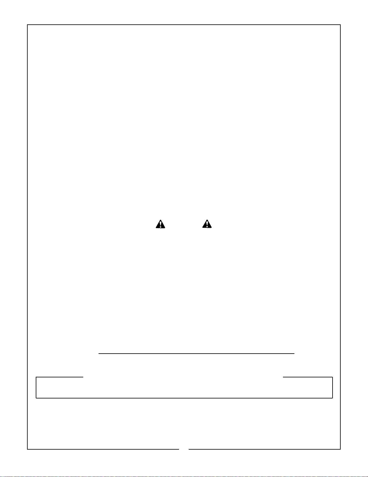
Model 3860 QT Technical Specifications
G
E
J
C
B
A
H
F
D
G
E
J
C
H
F
D
A. Maximum Lift Height - Measured at Pivot Pin . . . .176"
B. Maximum Lift Height - Under Level Bucket . . . . . 170"
C. Clearance with Attachment Dumped 45º . . . . . . . 148"
D. Reach at Maximum Height . . . . . . . . . . . . . . . . . . . . 33”
E. Maximum Dump Angle . . . . . . . . . . . . . . . . . . . . . . . 34°
F. Reach with Bucket on Ground . . . . . . . . . . . . . . . . 89”
G. Maximum Rollback Angle . . . . . . . . . . . . . . . . . . . . 19°
H. Digging Depth . . . . . . . . . . . . . . . . . . . . . . . . . . . . 5”
J. Overall Height in Carry Position . . . . . . . . . . . . . . . 81”
U. Lift Capacity to Maximum Height - At Pivot Pin . . 4580 lbs.
V. Lift Capacity to Maximum Height -
31.5” Forward of Pivot Pin . . . . . . . . . . . . . . . . . . . 3680 lbs
W. Lift Capacity to 59” Height - At Pivot Pin . . . . . . . 7100 lbs.
X. Lift Capacity to 59” Height -
31.5” Forward of Pivot Pin . . . . . . . . . . . . . . . . . . . 4970 lbs.
Y. Breakout Force - At Pivot Pin . . . . . . . . . . . . . . . . 8400 lbs.
Z. Breakout Force - 31.5” Forward of Pivot Pin . 6050 lbs.
VV. Rollback Force at Maximum Height -
31.5” Forward of Pivot Pin . . . . . . . . . . . . . . . 7706lbs.
XX. Rollback Force at 59” Height -
31.5” Forward of Pivot Pin . . . . . . . . . . . . . . 6787 lbs.
ZZ. Rollback Force at Ground Level -
31.5” Forward of Pivot Pin . . . . . . . . . . . . . . 5250 lbs.
Raising Time - Ground Level to Full Height . . 5.7 sec.
Lowering Time - Full Height to Ground Level . 5.1 sec.
Bucket Dumping Time - Full Rollback
to Full Dump . . . . . . . . . . . . . . . . . . . . . . . . . . . 3.3 sec.
Bucket Rollback Time - Full Dump
.
to Full Rollback . . . . . . . . . . . . . . . . . . . . . . . . 3.8 sec.
Specififications based on tractor system of 2800 psi hydraulic pressure and 28 gpm pump capacity. Specifications will vary slightly
with different tractors.
SPECIFICATIONS BASED ON 1997 ASAE STANDARDS AND SUBJECT
TO CHANGE WITHOUT NOTICE
8
Page 11

2. INSTALLATION INSTRUCTIONS
CAUTION
EQUIP YOUR TRACTOR WITH A ROPS
CAB OR FRAME FOR YOUR PROTECTION.
SEE YOUR TRACTOR/ROPS OPERATOR
MANUAL FOR CORRECT SEAT BELT
USAGE.
Read entire instructions before beginning to install
the loader. Personal injury and machine damage
may be prevented if you read and understand these
instructions and special safety messages.
TRACTOR PREPARATION
TRACTOR FRONT TIRES - Use front tires of equal
size and maintain equal pressure in each tire. The
pressure of the front tires must be increased to the
maximum approved pressure recommended by the
tire manufacturer to compensate for additional load
placed on the tires with the Front End Loader. See
your tractor Operator Manual. Adjust the front tires to
the widest recommended setting on adjustable models for maximum stability. Front end weights must
NOT be used while loader is on the tractor.
Observe tractor preparation guide in loader Operator
Manual. Pay particular attention to “minimum tread
settings” information in your Mounting Kit Installation
Instructions.
TRACTOR REAR TIRES - Maintain equal pressure
in each of the rear tires. Use the widest recommended rear wheel setting for maximum stability.
IMPORTANT: Do not exceed the maximum load
capacity of the tires on your tractor. See Tire and
Wheel Specifications in tractor Operator Manual
for more information.
IMPORTANT NOTICE
This loader has both standard and metric
fasteners. Verify that the proper fasteners
are placed in the correct locations.
Do not tighten any bolts firmly until all
components are attached onto the tractor.
INSTALLATION
Position tractor on level hard surface.
Install mounting brackets on tractor as shown in
Installation Instructions included with your Mounting Kit.
Remove all loader components from shipping packag-
ing.
CAUTION
LIFT AND SUPPORT ALL LOADER COMPONENTS SAFELY.
HOSE KIT HOOKUP: Install hoses to loader hydraulic
steel tubing. Install male quick couplers (customer furnished) to 1/2” male pipe ends of hoses. Refer to
Figure 1.
Figure 1
(1) Loader hydraulic steel tubing.
(2) Remote hoses.
EXTERNAL VALVE, CONTROL VALVE, CABLE
CONTROL VALVE AND PFC VALVE HOOKUP:
Install valve working port hoses to loader hydraulic
steel tubing. Install valve kit to your tractor/loader as
described in instructions included with these kits.
CAUTION
WHEN PROPERLY INSTALLED, THE
TRACTOR REMOTE VALVE OR EXTERNAL VALVE CONTROL LEVER/LEVERS
WILL CONTROL THE HYDRAULIC CIRCUITS AS DESCRIBED ON PAGES 12 &
13. REFER TO TRACTOR OPERATOR
MANUAL FOR FURTHER EXPLANATION
OF TRACTOR REMOTE CONTROL
LEVER/LEVERS.
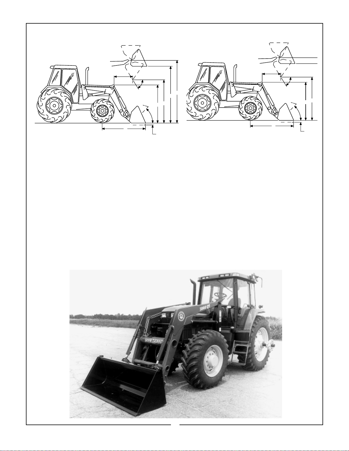
Front crossbrace assembly has been preassembled
at factory. This front crossbrace assembly is
adjustable and may have to be re-adjusted in the
field. Check measurement “A” from the front of the
center bracket tube to the forward side of front
bracket channel. Refer to Figure 2. This dimension
will be either 48-15/32” or 53-15/32”. Inspect your
loader and compare it to the subframe assembly.
Refer to Figures 3 & 4. If your loader dimension
does not match your tractor bracket dimension, then
disassemble front crossbrace assembly, relocate as
shown in drawings, and reinstall. Torque 3/4”
Grade 8 front crossbrace assembly bolts to 380
ft. lbs. six places.
9
Page 12
NOTE: Some Models of the 3860 Loader have
been designed to custom fit specific makes and
models of tractors. These will not require this
field change.
Figure 2
FRONT BRACKET
FORWARD SIDE
Quick Draw Latch Attach: Before installing loader
to tractor, install quick draw latch attach to loader.
Using a hoist, install bucket or attachment to your
quick draw latch attach. Refer to Figure 5 and pages
27 & 28 for quick draw latch attach instructions.
Following these instructions will add stability to
loader package and will allow easier handling of
loader with a hoist.
Figure 3
Figure 4
DIM. “A”
CENTER BRACKET TUBE
SUBFRAME ASSEMBLY
ADJUSTABLE TO
CLEAR HEADLIGHTS
FRONT CROSSBRACE
ASSEMBLY
48 15/32
SUBFRAME CROSSTUBE
SUBFRAME ASSEMBLY
ADJUSTABLE TO
CLEAR HEADLIGHTS
Figure 5
3
5
1
2
4
(1) Top pin 1-1/8” x 6-7/8”, 2 places.
(2) Bottom pin 1-1/8” x 6-7/8”, 2 places
(3) Clevis pin 5/16” x 2”, 4 places
(4) Cotter pin 1/8” x 1”, 4 places
(5) Quick Draw Latch Attach Adapter.
Remove hinge nuts and hardened flatwashers from
eyebolts. Swing hinge assemblies back. Reinstall
hardened flatwashers and hinge nuts onto eyebolts.
Remove snap pins from inner hole of rear hinge
pins and reinstall into outer holes of rear hinge pins.
Using snap pins as handles, remove rear hinge pins
and hinge assemblies from loader. Refer to Figure 6.
Figure 6
7
4
6
8
3
FRONT CROSSBRACE
ASSEMBLY
53 15/32
SUBFRAME CROSSTUBE
1
5
(1) Hinge nut.
(2) Hinge assembly.
(3) Loader mounted snap pin position.
(4) Hardened flatwasher.
(5) Rear hinge pin.
(6) Subframe bushing.
(7) Subframe pedestal.
(8) Rear hinge pin outer hole.
10
2
Page 13

Using a hoist to support the loader frame, align the
subframe crosstube with the front bracket. Refer to
Figure 7 and Figures 2, 3, & 4, page 10.
CAUTION
LIFT AND SUPPORT ALL LOADER COMPONENTS SAFELY.
1
8
9
3
Figure 9
(1) Hinge nut.
(2) Hinge assembly.
(3) Snap pin in loader mounted position.
(4) Hardened flatwasher.
(5) Rear hinge pin.
(6) Subframe bushing.
(7) Subframe pedestal.
(8) Center mounting bracket tubes.
(9) Rear hinge pin outer hole.
7
2
(1) Subframe Crosstube.
Figure 7
(2) Front Bracket.
Slowly drive the tractor forward until the subframe
crosstube is seated into the front bracket. Using
hoist, lower the front end loader until the subframe
assembly is seated on center bracket tubes. Refer to
Figures 2, 3, & 4, page 10.
Using snap pins as handles, reinstall rear hinge pins
and hinge assemblies. Remove snap pins from outer
holes of rear hinge pins and reinstall into inner holes.
Secure rear hinge pins to subframe bushings in
loader mounted position as shown in Figure 8.
Remove hinge nuts and hardened flatwashers from
eyebolts. Swing hinge assemblies forward. Secure
by locking hinge assemblies into position using hardened flatwashers and hinge nuts. Torque hinge nuts
to 200 ft. lb. Refer to Figures 8 & 9.
6
7
5
3
TORQUE IDENTIFICATION
Torque all mounting kit and loader hardware as
specified.
(A) Identify hardware size and grade.
(B) Refer to Torque Chart, page 43 and find correct
torque for your hardware size and grade.
(C) Torque hardware to this specification unless
otherwise specified.
IMPORTANT: Make sure that all front bracket to
tractor hardware and loader subframe to front
crossbrace assembly hardware has been
torqued properly before operating loader. Refer
to Figure 10.
Figure 10
Loader Subframe
Loader Subframe to
Front Crossbrace
Asembly (3 each side)
2
4
Loader Subframe
1
Front Crossbrace Assy.
FIGURE 8
Front Bracket to Tractor Bolts
(Quantity varies with Bracket Design
11
Page 14

3. PRE-OPERATION INSTRUCTIONS
IMPORTANT: Do not extend bucket cylinders
without quick draw latch attach installed on
loader. Failure to follow these instructions could
cause attachment cylinder damage and will void
loader warranty.
TRANSMISSION FLUID
Check the tractor hydraulic fluid level and fill, if
required.
INITIAL LOADER OPERATION
NOTE: Keep engine speed at low idle during the
initial loader operation.
CAUTION
ESCAPING HYDRAULIC FLUID UNDER
PRESSURE CAN HAVE SUFFICIENT FORCE
TO PENETRATE SKIN, CAUSING SERIOUS
PERSONAL INJURY. BEFORE DISCONNECTING LINES, BE SURE TO RELIEVE ALL
PRESSURE.
BEFORE APPLYING PRESSURE TO SYSTEM, BE SURE ALL CONNECTIONS ARE
TIGHT AND THAT LINES, TUBES AND
HOSES ARE NOT DAMAGED.
FLUID ESCAPING FROM A VERY SMALL
HOLE CAN BE ALMOST INVISIBLE. USE A
PIECE OF CARDBOARD OR WOOD, RATHER
THAN HANDS, TO SEARCH FOR SUSPECTED LEAKS.
IF INJURED BY ESCAPING FLUID, SEE A
DOCTOR AT ONCE. SERIOUS INFECTION
OR REACTION CAN DEVELOP IF PROPER
MEDICAL TREATMENT IS NOT ADMINISTERED IMMEDIATELY. REFER TO FIGURE 1.
EXTERNAL LOADER AND/OR
TRACTOR VALVE
CAUTION
WHEN PROPERLY INSTALLED, THE TRACTOR REMOTE VALVE OR EXTERNAL
VALVE CONTROL LEVER/LEVERS WILL
CONTROL THE LOADER HYDRAULIC CIRCUITS AS SHOWN IN FIGURES 2 AND 3.
REFER TO TRACTOR OPERATOR MANUAL
FOR FURTHER EXPLANATION OF TRACTOR REMOTE CONTROL LEVER/LEVERS.
IMPORTANT: Contaminants in hydraulic fluid
can cause valve spools to stick. BE ALERT when
operating loader and follow your tractor Operator
Manual hydraulic fluid maintenance schedule.
LOADER MOUNTED CONTROL VALVE
EQUIPPED WITH SINGLE LEVER CONTROL
HANDLE OR TRACTOR REMOTE VALVE
EQUIPPED WITH SINGLE LEVER CONTROL
HANDLE
If your loader utilizes a loader mounted control
valve equipped with single lever control handle
or tractor remote valve equipped with single
lever control handle, it will function as described
in Figure 2.
1
(1) Hydraulic line.
(2) Cardboard.
(3) Magnifying glass.
Figure 1
2
Front of Tractor
Figure 2
3
Number 1 Position: Pull the joystick back to
raise loader.
Number 2 Position: Push the joystick forward to
lower loader.
Number 3 Position: Push the joystick full forward
to activate float position.
Number 4 Position: Push the joystick outward to
dump attachment.
Number 5 Position: Pull the joystick inward to
roll back attachment.
12
Page 15

LOADER MOUNTED CONTROL VALVE
EQUIPPED WITH 2 OR 3 CONTROL HANDLES
OR TRACTOR REMOTE VALVE EQUIPPED WITH
2 OR 3 CONTROL HANDLES
If your loader utilizes a loader mounted control valve
equipped with 2 or 3 control handles or tractor
remote valve equipped with 2 or 3 control handles, it
will function as described in Figure 3.
Lift Cylinder Circuit
Pull the handle
back to raise unit
Attachment Cylinder Circuit
Pull the handle
back to roll
back attachment
Push the handle
forward to lower unit
Push the handle
forward to
dump attachment
Push handle full forward
to activate float position
CAUTION
BEFORE LEAVING THE TRACTOR SEAT,
LOWER ATTACHMENT OR LOADER BOOM
TO GROUND, STOP ENGINE, LOCK
BRAKES, RELIEVE HYDRAULIC PRESSURE,
AND REMOVE KEY.
IMPORTANT: Always keep the cylinders in a
retracted position when the loader is not in use
to guard against rust and contamination which
may cause damage to the cylinder rods and
hydraulic system.
REMOVING AIR FROM HYDRAULIC SYSTEM
Repeat raising and lowering the loader boom and
bucket operations until all the air is removed from
the system and the system responds properly.
3rd Cylinder (optional) Circuit
Pull the handle
back to open
assembly
Push the handle
forward to close
assembly
Figure 3
NEUTRAL POSITION
The loader external valve provided by Bush Hog has
a “neutral position” which prevents movement of the
loader or attachment. When the control handle is
manually released from the work position, the valve
spool will return to the neutral position.
FLOAT POSITION
The loader external valve provided by Bush Hog has
a “float position” incorporated into the lift cylinder circuit which allows the loader to float. This float feature is important for satisfactory operation when
scraping, sweeping, leveling, or any job where it is
necessary to follow the contour of the surface. To
activate the float position, lower the bucket or
attachment and push the control handle all the way
forward into detent. The valve will stay in float detent
position until the operator manually pulls the control
handle out of detent position to deactivate float.
HOSE IDENTIFICATION
Check if loader functions as shown and described in
Figures 2 and 3. Then install colored nylon ties, one
color per each circuit. Locate nylon ties so one is
attached to male side of quick coupler and one is
attached to female side of quick coupler. This will
allow easy identification of loader circuits when
mounting and dismounting loader.
BUCKET LEVEL INDICATOR
BLI (bucket level indicator) rod has been preassembled to loader linkage pin at the factory.
BLI (bucket level indicator) must be adjusted during
initial loader set up. Adjust the BLI as follows:
Position the bucket level on the ground. Loosen the
BLI clamp holding the BLI tube, and align the BLI
tube so that it is flush with end of the BLI rod, then
retighten BLI clamp. When operating loader, use the
attachment cylinder controls to align the BLI rod so
that it is flush with the end of the BLI tube. This will
inform the operator that the bucket and/or attachment bottom is level with ground. Refer to Figure 4.
Bucket Level
Indicator
INITIAL LOADER OPERATION
Before operating the loader, fully raise and lower the
boom two or three times. Then raise the loader
bucket approximately four (4) feet above the ground
and cycle the bucket cylinders two or three times.
Lower the bucket or attachment to the ground.
Check the tractor hydraulic fluid level and fill as
required. Refer to the tractor Operator Manual for
the proper hydraulic fluid and the correct hydraulic
fluid level.
Figure 4
13
Page 16

REMOTE HOSES SUPPORT
After installing loader onto tractor, raise the loader to
full height, stop engine, lock brakes, and remove
key. Then gather remote hoses and install nylon tie
through hose support hole located in right hand
loader subframe. Secure hoses as shown. This will
allow remote hoses to be supported by loader frame
instead of loader steel tubing. Refer to Figure 5.
CAUTION
DO NOT STAND, WALK OR WORK UNDER
A RAISED LOADER OR ATTACHMENT
UNLESS IT IS SECURELY BLOCKED OR
HELD IN POSITION. ACCIDENTAL MOVEMENT OF A CONTROL LEVER/LEVERS OR
LEAKS IN THE HYDRAULIC SYSTEM
COULD CAUSE THE LOADER TO DROP,
OR ATTACHMENT TO DUMP, CAUSING
SEVERE INJURY.
3
5
4
THIRD CYLINDER TUBE KIT
(OPTIONAL)
Install two steel tubes to inside of right hand loader
boom. Then connect the two hoses and fittings to
the front of the steel tubes. Refer to Figure 6 for further installation instructions.
NOTE: Hydraulic hoses from third cylinder steel
tubes to tractor rear remotes are not supplied in
this kit.
1
2
Figure 5
(1) Nylon tie
(2) Snap pin (note location)
(3) Remote hoses
(4) Subframe (right-hand shown)
(5) Right hand support hole located in subframe
Figure 6
(1) Steel tubes.
(2) Existing tube clamp, 2 places.
(3) New tube clamp, secure using 3/8" nylon locknut.
(4) Fitting, 90° JICM 3/4" x JICF 3/4", install one on
each tube.
(5) Hoses 3/8" x 80", installed to fitting on steel
tubes.
(6) Install hose protector over hoses. Secure each
end using nylon ties.
(7) Male and female quick couplers, supplied with
attachment. Connect one to each hose.
14
Page 17

4. MAINTENANCE
DAILY CHECKS
Check all hardware daily before operation.
Tighten hardware to torque values as specified in
the Torque Chart, page 43 unless otherwise specified.
With the engine off and the bucket on the ground,
inspect all hoses for cuts or wear. Check for signs of
leaks and make sure all fittings are tight.
CAUTION
ESCAPING HYDRAULIC FLUID UNDER
PRESSURE CAN HAVE SUFFICIENT
FORCE TO PENETRATE SKIN, CAUSING
SERIOUS PERSONAL INJURY. BEFORE
DISCONNECTING LINES, BE SURE TO
RELIEVE ALL PRESSURE.
BEFORE APPLYING PRESSURE TO SYSTEM, BE SURE ALL CONNECTIONS ARE
TIGHT AND THAT LINES, TUBES, AND
HOSES ARE NOT DAMAGED.
FLUID ESCAPING FROM A VERY SMALL
HOLE CAN BE ALMOST INVISIBLE. USE A
PIECE OF CARDBOARD OR WOOD,
RATHER THAN HANDS, TO SEARCH FOR
SUSPECTED LEAKS.
IF INJURED BY ESCAPING FLUID, SEE A
DOCTOR AT ONCE. SERIOUS INFECTION
OR REACTION CAN DEVELOP IF PROPER
MEDICAL TREATMENT IS NOT ADMINISTERED IMMEDIATELY. REFER TO FIGURE 1.
IMPORTANT: Lower the loader boom to the
ground and relieve pressure in loader hydraulic
lines prior to doing any service or maintenance
operations on the tractor or loader.
Check the tractor hydraulic fluid level as specified in the tractor Operator Manual.
NOTE: When checking hydraulic system fluid
level, the loader boom must be on the ground
with the bucket or attachment resting flat on a
level surface.
LOADER LUBRICATION
Position bucket and/or attachment level with ground,
lower loader boom to ground, and relieve all
hydraulic pressure before lubricating. Refer to
Figures 2 & 3.
There are 16 grease fittings on the Model 3860
Loader, one at each pivot point. Lubricate pivots as
specified.
1
1
1
Figure 1
2
3
1
(1) Hydraulic line.
(2) Cardboard.
(3) Magnifying glass.
Service your loader at the intervals and locations as
specified. When you service your loader, use only
high quality lubricants. The engine hour meter on the
tractor shows the amount of hours the engine has
worked. Use the hour meter to service your loader at
the correct time periods.
Figure 2
2
2
2
Figure 3
(1) Lubricate these 8 pivot points every 10 hours of
operation.
(2) Lubricate these 8 pivot points every 5 hours of
operation.
15
1
2
Page 18

CAUTION
DO NOT STAND, WALK OR WORK UNDER
A RAISED LOADER OR ATTACHMENT
UNLESS IT IS SECURELY BLOCKED OR
HELD IN POSITION. ACCIDENTAL MOVEMENT OR A CONTROL LEVER/LEVERS OR
LEAKS IN THE HYDRAULIC SYSTEM
COULD CAUSE THE LOADER TO DROP,
OR ATTACHMENT TO DUMP, CAUSING
SEVERE INJURY.
QUICK DRAW LATCH ATTACH LUBRICATION
Your quick draw latch attach handle springs and pin
areas have been pre-lubricated and sealed at the
factory. If handle pin sticking occurs: remove spring
cover plates, lubricate spring and pin areas, reinstall
cover plates, and seal plates using a 1/4" bead of
Sika-Flex sealant. Refer to Figure 4.
5. OPERATING INSTRUCTIONS
1
Figure 4
(1) Spring cover plate, one each side.
GENERAL SAFETY
Only qualified people familiar with this operator’s
manual should operate this machine. Operator
should wear hard hat, safety glasses and safety
shoes. The operator should read, understand and
practice all safety messages shown on the caution,
warning and danger decals affixed to the loader to
avoid serious injury or death. It is recommended that
tractor be equipped with Rollover Protective System
(ROPS) and a seat belt be used per tractor manufacturer’s recommendations. Check for ditches,
stumps, holes or other obstacles that could upset
tractor or damage loader. Always turn off tractor
engine, set parking brake and lower loader to ground
before leaving tractor operator’s seat.
BUCKET LEVEL GAUGE ROD
The bucket level gauge rod (Figure 4, page 13) can
be used to determine bucket angle. Before beginning work, observe the position of gauge rod with
bucket flat on ground. Raise boom to several different positions. At each position, level bucket, then
observe gauge rod. Once familiar with the gauge rod
positions, operation of the loader will be easier and
more efficient.
OPERATION
The loader should be operated with the tractor
engine running at 1200-1700 rpm. Excessive speeds
are dangerous and may cause bucket spillage and
unnecessary strain on both the tractor and loader.
When operating in temperatures below 30°F, run the
tractor engine belolw 1200 rpm until the hydraulic
fluid temperature exceeds 30°F.
The following text and illustrations offer suggested
loader and tractor operating techniques.
16
Page 19

FILLING THE BUCKET
Approach and enter the pile with a level bucket.
Loaders with 1-lever control, ease lever back and
toward you to lift and rollback the bucket.
...a level bucket throughout the lifting cycle resists
bucket lift and increases breakaway effort.
NOTE; Do not be concerned if the bucket is not completely filled during each pass. Maximum productivity
is determined by the amount of material loaded in a
given period of time. Time is lost if two or more
attempts are made to fill the bucket on each pass.
LIFTING THE LOAD
WARNING
DO NOT LIFT OR CARRY ANYONE IN THE
BUCKET OR ON ANY OTHER PORTION OF
THE LOADER OR LOADER ATTACHMENT.
INADVERTENT MOVEMENT OF THE
LOADER OR ATTACHMENT COULD
RESULT IN SERIOUS INJURY OR DEATH
FROM FALLING OR CRUSHING.
Loaders with 2-lever controls, ease both levers back
to lift and rollback the bucket.
The lift and rollback of the bucket will increase efficiency because...
CAUTION
MAKE SURE MATERIAL IN BUCKET CANNOT ROLL OUT AND DOWN ON TRACTOR
WHEN BUCKET IS RAISED TO FULL
HEIGHT. KEEP CLEAR OF OVERHEAD
OBSTRUCTIONS SUCH AS TREES, LIMBS
OR POWER LINES WHEN RAISING THE
BUCKET
When lifting the load, keep the bucket positioned to
avoid spillage.
17
CAUTION
DO NOT ATTEMPT TO LIFT BUCKET
LOADS IN EXCESS OF CAPACITIES
LISTED IN TECHNICAL SPECIFICATIONS.
Page 20

CARRYING THE LOAD
DUMPING THE BUCKET
Position the bucket as low as possible below the
level of the tractor hood for maximum stability and
visibility, whether the bucket is loaded or empty.
Use extreme caution when operating the loader on a
slope and keep the bucket as low as possible. This
keeps the bucket and tractor center of gravity low
and will provide maximum tractor stability.
CAUTION
OPERATING THE LOADER ON A HILLSIDE
IS DANGEROUS. EXTREME CARE IS
RECOMMENDED.
Lift the bucket high enough to clear the side of the
vehicle. Move the tractor in as close to the side of
the vehicle as possible, then dump the bucket.
LOWERING THE BUCKET
After the bucket is dumped, back away from the
vehicle while lowering and rolling back the bucket.
FLOAT POSITION
LOWER
DUMP
DO THIS NOT THIS
When transporting the load, keep the bucket as low
as possible to avoid tipping, in case a wheel drops in
a rut.
NOT THIS
DO THIS
1-LEVER
CONTROL
ROLLBACK
FLOAT POSITION
LOWER
2-LEVER
CONTROLS
RAISE
DUMP
ROLLBACK
RAISE
18
Page 21

OPERATING WITH FLOAT CONTROL
During hard surface operation, keep the bucket level
and put the lift control in the float position to permit
the bucket to float on the working surface. If
hydraulic down pressure is exerted on the bucket, it
will wear faster than normal.
FLOAT
The float will also prevent the mixing of surface
material with stockpile material. The float position
will reduce the chance of surface gouging when
removing snow or other material.
FLOAT
Sidecutting is a good technique for cutting down a
big pile.
If the piles are too high and liable to cause cave-in,
use the loader to break down the sides until a slot
can be cut over the top.
SURFACE MATERIAL
LOADING FROM A BANK
Choose a forward gear that provides sufficient
ground speed for loading.
Exercise caution when undercutting high banks. Dirt
slides can be dangerous. Load from as low as possible for maximum efficiency. Loader lift and breakaway capacity diminish as loading height is
increased.
Another method for large dirt piles is to build a ramp
approach to the pile.
It’s important to keep the bucket level when
approaching a bank or pile. this will help prevent
gouging the work area.
19
Page 22

PEELING AND SCRAPING BACKFILLING
6”
Backgrade occasionally with a loaded bucket to
Use a slight bucket angle, travel forward, and hold the
lift control forward to start the cut. Make a short, angle
cut approximately 6” deep and break-out cleanly.
keep the working surface free of ruts and holes.
Hold the lift control forward in float position so the
full weight of the bucket is scraping the ground.
Use only the heel of the bucket while backgrading.
IMPORTANT: To prevent damage to cylinders:
(1) Do not backgrade with bucket cylinders extended.
(2) Always backgrade with valve in float position.
With the bucket level, start a cut at the notch approximately 2” deep. Hold the depth by feathering the
bucket control to adjust the cutting lip up or down.
When the front tires enter the notch, adjust the lift
cylinder to maintain proper depth.
3RD CUT , 4TH CUT, ETC.
Make additional passes until the desired depth is
reached. During each pass, only use the bucket control while at working depth. This will allow you to
concentrate on controlling the bucket angle to maintain a precise cut.
LOADING LOW TRUCKS OR SPREADERS FROM
A PILE
DO THIS
Approach the pile with a flat bucket.
NOT THIS
For faster loading, minimize the angle of turn and
length of run between pile and spreader.
Poor methods actually move no more dirt and make
it more difficult to hold a level grade.
Do not use the bucket in the dumped position for
bulldozing or backgrading. This method, shown
above, will impose severe shock loadings on the
dump linkage, the bucket cylinder, and the tractor.
20
Page 23

Leave dirt in the bucket because dumping on each
pass wastes time.
HANDLING LARGE HEAVY OBJECTS
WARNING
DO NOT USE FRONT END LOADERS FOR
HANDLING LARGE HEAVY OBJECTS SUCH
AS LOGS OR OIL DRUMS. HANDLE LARGE
ROUND HAY BALES ONLY WHEN LOADER
IS EQUIPPED WITH BUSH HOG BALE
SPEAR ATTACHMENT OR BUCKET WITH 4
TINE GRAPPLE.
HANDLING LARGE HEAVY OBJECTS CAN
BE EXTREMELY DANGEROUS DUE TO:
DITCH
SOIL PILE
Operate at right angles to the ditch. Take as big a
bite as the tractor can handle without lugging down.
DITCH
Leave dirt which drifts over the side of the bucket for
final clean-up.
★ Possibility of rolling the tractor over.
★ Possibility of upending the tractor.
★ Possibility of the object rolling or sliding
down the loader arms onto the operator.
BACK GRADING
When back grading, the angle between the bottom
of the bucket and the ground must not be more than
15 degrees. Refer to Figure 1.
Failure to follow these instructions could cause
loader attachment cylinders to fail and void warranty.
Pile dirt on the high side for easier backfilling on a
slope.
15 Degrees
Figure 1
21
Page 24

TROUBLESHOOTING PROCEDURES
PROBLEM POSSIBLE CAUSE REMEDY
Loader slow and/or will not dump. Hydraulic oil to heavy. Change to proper oil.
Oil filter plugged. Clean or replace filter.
Hydraulic pump worn. Repair or replace pump.
Oil line restricted or leaking. Check all hoses and tubes for leaks,
Quick couplers not properly connected. Check connection - Replace if necessary.
Control valve does not shift properly. Inspect clean, repair or replace valve.
Air in hydraulic system. Cycle lift cylinders and bucket cylinders
Cylinder leaks internally. Replace seals.
Faulty valve. Repair or replace valve.
Loader chatters or vibrates when Air in hydraulic system. Cycle lift cylinders and bucket cylinders.
raising or lowering.
Oil leaks. Damaged fittings or hoses. Replace damaged parts.
Oil level too low. Add oil as required.
Loose connections. Tighten fittings.
Worn or damaged O-ring or Install a seal repair kit.
wiper seal in cylinder rod end.
Worn or damaged O-rings in Install an O-ring repair kit.
valve.
damage or restrictions. Replace
damaged or restricted hoses or tube lines.
several times to free system of air.
Insufficient lift capacity. Load is greater Check loader specifications.
Slow leakdown. Worn control valve. Have authorized Bush Hog dealer replace
Excessive wear on bottom of bucket Float position not used while Use float position provided on valve.
and wear pads. operating loader.
Hydraulic cylinders inoperative. Hose from control valve improperly Refer to plumbing diagrams in Section V.
Pump operating continually on closed Hydraulic control valve relief stuck See your tractor manual for proper adjustcenter tractor hydraulic system. open. ment or Bush Hog dealer for loader valve.
Loader lift and bucket tilt controls do not work Hoses improperly connected. Refer to plumbing diagrams in Section V
according to decal. and correct hose connections.
Valve noisy and/or hot. Open center control valve on Install closed center plug on optional valve.
Tractor loads/pump squeals. Closed center control valve on open Install open center plug on optional valve.
than boom lift capacity. Check tractor system.
Internal boom cylinder leakage. Replace any worn parts and install a seal
repair kit.
Improper hydraulic valve Repair or replace valve.
operation.
seals.
Worn cylinder piston seals. Have authorized Bush Hog dealer replace
seals.
connected.
Hydraulic control valve relief set (3000 PSI is maximum pressure relief
too low. setting recommended)
closed center tractor.
center tractor.
22
Page 25

6. DISMOUNTING THE LOADER
CAUTION
ALWAYS PARK LOADER WITH MATERIAL
BUCKET OR AUTHORIZED BUSH HOG
ATTACHMENT ATTACHED TO THE LOADER.
BEFORE LEAVING THE TRACTOR SEAT,
LOWER ATTACHMENT OR LOADER BOOM
TO GROUND, STOP ENGINE, LOCK
BRAKES, RELIEVE HYDRAULIC PRESSURE
AND REMOVE KEY.
DO NOT STAND, WALK, OR WORK UNDER A
RAISED LOADER OR ATTACHMENT UNLESS
IT IS SECURELY BLOCKED OR HELD IN
POSITION. ACCIDENTAL MOVEMENT OF A
CONTROL LEVER/LEVERS OR LEAKS IN
THE HYDRAULIC SYSTEM COULD CAUSE
THE LOADER TO DROP, OR ATTACHMENT
TO DUMP, CAUSING SEVERE INJURY.
DO NOT ALLOW BYSTANDERS IN LOADER
WORK AREA.
IMPORTANT: Never allow weight of tractor to be
placed on parking stands when mounting or dismounting loader.
Position the tractor/loader on a hard level surface.
Raise loader boom assembly. Position the bucket
90° to the ground. Then lower the loader boom until
front edge of bucket is resting on the ground. Refer
to Figure 1.
Remove the two clevis pins holding the two parking
stands in the storage position. Refer to Figure 2.
1
2
Figure 2
(1) Clevis pin 5/8" x 4-1/2", one each side of loader.
(2) Clevis pin 5/8" x 4", one each side of loader.
Rotate the parking stands rearward into the park
position and secure using clevis pins and hairpin
cotters. Remove the two clevis pins holding lower
legs of parking stands in the retracted position.
Extend the parking stands and reinstall clevis pins to
hold lower legs in the park position. Refer to Figure 3.
Figure 1
1
2
3
Figure 3
(1) Clevis pin 5/8" x 4-1/2", one each side of loader.
(2) Clevis pin 5/8" x 4", one each side of loader.
(3) Lower parking stand leg extended.
23
Page 26

Raise the loader boom and retract the bucket cylinders. Lower the loader boom until the parking stands
make contact with the ground. Dump the bucket until
the bucket touches the ground. Refer to Figure 4.
Figure 4
NOTE: Driving the tractor forward slowly while
positioning loader will allow parking stands to
contact ground firmly. Using float position during this operation will keep tractor weight from
being applied to loader parking stands.
7
Figure 6
Start the tractor and position the valve control lever
in the float position. Retract the bucket cylinder until
the subframe assembly lifts off of the center bracket
tubes. Take the valve control lever out of the float
position. Back the tractor up approximately one foot.
Make sure hydraulic hoses are not pulled or damaged. Refer to Figure 7.
8
9
3
Remove hinge nuts and hardened flatwashers from
eyebolts. Swing hinge assemblies back. Reinstall
hardened flatwashers and hinge nuts onto eyebolts.
Remove snap pins from inner hole of rear hinge pins
and reinstall into outer holes of rear hinge pins.
Using snap pins as handles, remove rear hinge pins
and hinge assemblies from loader. Figures 5 & 6.
6
7
4
1
2
Figure 5
(1) Hinge nut.
(2) Hinge assembly.
(3) Loader mounted snap pin position.
(4) Hardened flatwasher.
(5) Rear hinge pin.
(6) Subframe bushing.
(7) Subframe pedestal.
(8) Center mounting bracket tubes. (Figure 6)
(9) Rear hinge pin outer hole. (Figure 6)
5
3
Figure 7
NOTE: Before backing the tractor away from the
loader, use the lift cylinders to position the subframe crosstube so it moves freely in the front
bracket channel. This will prevent loader movement when backing the tractor away from the
loader.
Make sure the subframe assembly will clear the front
wheels and axle of the tractor. Retract the lift and
attachment cylinders. Stop the tractor engine and
then work valve control lever/levers to relieve
hydraulic fluid pressure in lines. See tractor Operator
Manual for additional information.
24
Page 27

Reinstall hinge assemblies, rear hinge pins, and
snap pins to loader for storage. Disconnect the
hoses at the quick couplers. Start the tractor. Slowly
back the tractor away from the loader. Refer to
Figure 8.
Figure 8
7. MOUNTING THE LOADER
CAUTION
BEFORE LEAVING THE TRACTOR SEAT,
LOWER ATTACHMENT OR LOADER BOOM
TO GROUND, STOP ENGINE, LOCK
BRAKES, RELIEVE HYDRAULIC PRESSURE, AND REMOVE KEY.
IMPORTANT: To avoid hydraulic hose damage,
be alert and make sure hoses do not catch on
tractor and/or loader during mounting or dismounting.
WARNING
MAKE SURE PARKED LOADER IS ON A
HARD LEVEL SURFACE. ENGAGE ALL
SAFETY DEVICES TO PREVENT LOADER
FROM FALLING AND BEING DAMAGED
OR INJURING SOMEONE. DO NOT REPAIR
LOADER IF IT IS NOT MOUNTED ON THE
TRACTOR. LOSS OF HYDRAULIC FLUID
OR REMOVAL OF PARTS COULD CAUSE
LOADER TO COLLAPSE RESULTING IN
INJURY.
Use the lift and attachment cylinders to align the
subframe crosstube with the front bracket. Drive the
tractor forward to install the subframe crosstube into
the front bracket. Refer to Figure 1.
DO NOT STAND, WALK OR WORK UNDER
A RAISED LOADER OR ATTACHMENT
UNLESS IT IS SECURELY BLOCKED OR
HELD IN POSITION. ACCIDENTAL MOVEMENT OR A CONTROL LEVER/LEVERS OR
LEAKS IN THE HYDRAULIC SYSTEM
COULD CAUSE THE LOADER TO DROP,
OR ATTACHMENT TO DUMP, CAUSING
SEVERE INJURY.
DO NOT ALLOW BYSTANDERS IN
LOADER WORK AREA
IMPORTANT: Never allow weight of tractor to be
placed on parking stands when mounting or dismounting loader.
Slowly drive tractor to a position where the hoses
can be connected to the quick couplers. Stop the
engine. Connect the loader hydraulic hoses to the
correct couplers. Refer to Figure 8 at top of page.
Remove rear hinge assemblies from loader.
1
2
Figure 1
(1) Subframe crosstube.
(2) Front bracket.
25
Page 28

Extend the attachment cylinders to lower loader subframes onto center mounting bracket tubes. Refer to
Figure 2.
1
Remove the two clevis pins holding lower legs of
parking stands in the park position. Retract the parking stands and reinstall clevis pins to hold lower legs
in the storage position Refer to Figure 4.
1
Figure 2
(1) Subframe being lowered to center mounting
bracket.
Using snap pins as handles, reinstall rear hinge pins
and hinge assemblies. Remove snap pins from outer
holes of rear hinge pins and reinstall into inner
holes. Secure rear hinge pins to subframe bushings
in loader mounted position. Remove hinge nuts and
hardened flatwashers from eyebolts. Swing hinge
assemblies forward. Secure by locking hinge assemblies into position using hardened flatwashers and
hinge nuts. Torque hinge nuts to 200 ft. lb. Refer to
Figures 5 & 6, page 24.
Raise the loader boom and position the bucket 90°
to the ground. Lower the loader boom assembly until
front edge of bucket is resting on the ground. Refer
to Figure 3.
2
3
Figure 4
(1) Clevis pin 5/8" x 4-1/2", one each side of loader.
(2) Clevis pin 5/8" x 4", one each side of loader.
(3) Lower parking stand leg extended.
Remove parking stands from parked position and
return to storage position. Secure parking stands in
storage position using clevis pins and hairpin cotters. Refer to Figure 5.
Figure 3
1
2
Figure 5
(1) Clevis pin 5/8" x 4-1/2", one each side of loader.
(2) Clevis pin 5/8" x 4", one each side of loader.
26
Page 29

8. INSTALLATION & OPERATION OF
QUICK DRAW LATCH ATTACH
WARNING
ALWAYS READ AND FOLLOW OPERATING INSTRUCTIONS BEFORE OPERATING
QUICK DRAW LATCH ATTACH.
INSTALLATION INSTRUCTIONS
IMPORTANT: Do not extend bucket cylinders
without quick draw latch attach installed on
loader. Failure to follow these instructions will
void loader warranty.
Install quick draw latch attach to loader using four (4)
pins as specified below. Secure pins using clevis
pins and cotter pins, 4 places. Refer to Figure 1.
3
5
OPERATING INSTRUCTIONS
CAUTION
EXCEPT WHEN DETACHING OR ATTACHING A QUICK DRAW BUCKET OR ATTACHMENT TO YOUR QUICK DRAW LATCH
ATTACH, ALWAYS POSITION THE QUICK
DRAW HANDLE IN THE HANDLE
ENGAGED POSITION, FIGURE 6, PAGE 28
THIS WILL PREVENT ACCIDENTAL TRIPPING OF QUICK DRAW HANDLE WHEN
NOT IN USE.
TO AVOID PERSONAL INJURY, KEEP
HANDS AWAY FROM LOADER WHEN
OPERATING.
IMPORTANT: To maintain your quick draw latch
attach functioning properly, always inspect
quick draw latch attach and quick draw handle
linkage components for damage. If damage
exists, replace component immediately.
IMPORTANT: To maintain your quick draw latch
attach functioning properly, always keep quick
draw latch attach, loader push off bar, quick
draw handle linkages, and pin areas clean. Refer
to Figure 2.
1
2
4
Figure 1
(1) Top pin 1-1/8" x 6-7/8", 2 places.
(2) Bottom pin 1-1/8" x 6-7/8", 2 places.
(3) Clevis pin 5/16" x 2", 4 places.
(4) Cotter pin 1/8" x 1", 4 places.
(5) Quick Draw Latch Attach Adapter.
4
5
1
(1) Quick draw latch attach.
(2) Quick draw handle.
(3) Quick draw notch.
(4) Loader push off bar.
(5) Quick draw handle linkages.
(6) Quick draw pin area.
27
Figure 2
2
3
6
Page 30

IMPORTANT: The quick draw latch attach must only be used in combination with quick draw buckets or
attachments. To verify that your bucket or attachment can be used with your quick draw latch attach,
inspect inside of upper channel to see that weld-in center support has been incorporated within channel section. Refer to Figure 3. If your bucket or attachment does not incorporate this support, consult
your Bush Hog Dealer.
Figure 3
(1) Upper channel.
(2) Weld-in center support.
(3) Bucket or attachment.
QUICK DRAW HANDLE DISENGAGED POSITION:
To position quick draw handle into the handle disengaged position, pull quick draw handle to the left as
shown in Figure 4 and then lock into quick draw
notch as shown in Figure 5.
Figure 4
(1) Handle disengaged position.
QUICK DRAW HANDLE ENGAGED POSITION:
Figure 6 shows quick draw handle in the handle
engaged position. When quick draw handle is in this
position, quick draw handle must line up with handle
engaged arrow located on Warning Decal. Refer to
Figure 5.
Figure 6
(2) Handle engaged position.
Figure 5
(3) Quick draw notch.
(4) Handle engaged arrow of decal.
28
Page 31

9. INSTALLING BUCKET OR ATTACHMENT TO
QUICK DRAW LATCH ATTACH
IMPORTANT: Refer to page 28 for instructions
concerning Quick Draw Handle Disengaged and
Engaged Positions.
CAUTION
BEFORE LEAVING THE TRACTOR SEAT,
LOWER ATTACHMENT OR LOADER
BOOM TO GROUND, STOP ENGINE,
LOCK BRAKES, RELIEVE HYDRAULIC
PRESSURE, AND REMOVE KEY.
DO NOT STAND, WALK OR WORK
UNDER A RAISED LOADER OR ATTACHMENT UNLESS IT IS SECURELY
BLOCKED OR HELD IN POSITION. ACCIDENTAL MOVEMENT OF A CONTROL
LEVER/LEVERS OR LEAKS IN THE
HYDRAULIC SUSTEM COULD CAUSE
THE LOADER TO DROP, OR ATTACHMENT TO DUMP, CAUSING SEVERE
INJURY.
OPERATING INSTRUCTIONS
To attach quick draw bucket or attachment to loader,
lower loader boom to ground with quick draw latch
attach rolled forward slightly. Pull quick draw handle
into the handle disengaged position and lock into
quick draw notch. Refer to Figure 1.
Figure 2
(1) Align quick draw tubes with quick draw attachment channel.
NOTE: Over extension of attachment cylinders
during this operation could cause damage to
quick draw handle due to handle contacting
quick draw bucket or attachment.
When quick draw latch attach is aligned with quick
draw bucket or attachment, raise loader boom slowly
making sure quick draw tubes engage into quick
draw attachment channel. Then roll quick draw
bucket attachment back slowly. This will push quick
draw handle forward securing quick draw bucket or
attachment to quick draw latch attach. Refer to
Figure 3.
Figure 1
(1) Quick draw handle located in handle disengaged
position.
Roll quick draw latch attach forward by extending
attachment cylinders just enough to allow quick draw
tubes to engage quick draw attachment channel.
Drive tractor forward, aligning quick draw tubes with
the quick draw attachment channel. Refer to Figure 2.
NOTE: This operation must be done with quick
draw bucket or attachment positioned close to
ground to allow loader push off bar to function
correctly.
Figure 3
29
Page 32

Check to see that quick draw handle has moved to
the handle engaged position by rolling quick draw
bucket or attachment back and then raising loader
boom to hood height.
NOTE: Quick draw handle must be located in the
handle engaged position. Refer to Figure 4 below
and to Figures 5 and 6 page 28.
Figure 4
Inspect quick draw attaching areas to verify that
quick draw pins have engaged quick draw bucket or
attachment fully. Refer to Figure 6.
Check that quick draw bucket or attachment is
securely attached to quick draw latch attach by raising loader boom 3 to 4 feet, dumping quick draw
bucket or attachment against stops, and checking to
be sure quick draw bucket or attachment does not
roll out of quick draw latch attach. Refer to Figure 5.
Figure 5
Figure 6
(1) Quick draw pin.
(2) Quick draw pin bushing.
(3) Quick draw bucket or attachment engaging bar.
If installing an attachment utilizing a third cylinder
hydraulic circuit, connect loader hose quick couplers
to attachment quick couplers.
WARNING
A QUICK DRAW BUCKET OR ATTACHMENT
THAT IS NOT SECURELY LOCKED INTO
QUICK DRAW LATCH ATTACH COULD
COME OFF DURING LOADER OPERATION
CAUSING SERIOUS INJURY OR DEATH.
30
Page 33

10. REMOVING BUCKET OR ATTACHMENT FROM
QUICK DRAW LATCH ATTACH
IMPORTANT: Refer to page 28 For instructions
concerning Quick Draw Handle Disengaged and
Engaged Positions.
CAUTION
BEFORE LEAVING THE TRACTOR SEAT,
LOWER ATTACHMENT OR LOADER BOOM
TO GROUND, STOP ENGINE, LOCK
BRAKES, RELIEVE HYDRAULIC PRESSURE, AND REMOVE KEY.
DO NOT STAND, WALK OR WORK UNDER
A RAISED LOADER OR ATTACHMENT
UNLESS IT IS SECURELY BLOCKED OR
HELD IN POSITION. ACCIDENTAL MOVEMENT OF A CONTROL LEVER/LEVERS OR
LEAKS IN THE HYDRAULIC SUSTEM
COULD CAUSE THE LOADER TO DROP, OR
ATTACHMENT TO DUMP, CAUSING
SEVERE INJURY.
OPERATING INSTRUCTIONS
To disconnect quick draw bucket or attachment from
loader, position bucket or attachment level with
ground and approximately 1" off of ground. Refer to
Figure 1. Then pull quick draw handle into the handle disengaged position and lock into quick draw
notch. Refer to Figure 4, page 28.
Roll quick draw bucket or attachment forward and
lower to ground. Back tractor/loader away from quick
draw bucket or attachment. Refer to Figure 2. Then
roll quick draw latch attach back so quick draw handle returns to the handle engaged position. Refer to
Figure 6, page 28.
Figure 2
NOTE: Over extension of attachment cylinders
during this operation could cause damage to
quick draw handle due to handle contacting
quick draw bucket or attachment.
(1) Quick draw handle.
If removing an attachment utilizing a third cylinder
hydraulic circuit, disconnect loader hose quick couplers from attachment quick couplers. Secure and
store loader hoses on loader frame.
Figure 1
31
Page 34

11. BUCKET ATTACHMENT
QUICK DRAW BUCKET
IMPORTANT: Refer to pages 29 & 30 for instruc-
tions concerning Installing Attachment to Quick
Draw Latch Attach.
IMPORTANT: Refer to page 31 for instructions
concerning Removing Attachment from Quick
Draw Latch Attach.
Quick draw buckets are available as follows.
72 inch, 84 inch, and 96 inch wide for Bush Hog
3860 Loaders.
These buckets utilize a replaceable weld-on cutting
edge, and are pre-punched for tines.
Heavy duty/high capacity quick draw buckets are
available as follows.
72 inch, 84 inch, 96 inch, and 102 inch wide for Bush
Hog 3860 Loaders.
These buckets utilize a replaceable bolt-on cutting
edge.
These buckets are equipped with a clevis mounting
point for lifting. Refer to Figure 1.
CAUTION
NEVER LIFT ANY LOAD FROM ANY POINT
OF THE LOADER WITH A CHAIN, ROPE, OR
CABLE UNLESS LOADER IS EQUIPPED
WITH A BUSH HOG FACTORY APPROVED
ATTACHMENT WHICH WAS DESIGNED
AND BUILT FOR THIS TYPE OF LIFTING.
ALWAYS FOLLOW LIFTING INSTRUCTIONS
INCLUDED WITH THIS ATTACHMENT.
NEVER TOW FROM ANY POINT OF THE
LOADER WITH A CHAIN, ROPE, OR
CABLE. DOING SO COULD CAUSE A ROLL
OVER OR SERIOUS DAMAGE TO THE
LOADER.
Figure 1
(1) Bucket, heavy duty, high capacity.
(2) Clevis mounting point.
(3) Clevis (use only Factory approved clevis).
(4) Clevis pin.
(5) Cotter Pin.
SINGLE TINE KIT
Single tine kits are available for mounting on prepunched buckets as follows. Each single tine kit
includes one tine and attaching hardware.
72 inch quick draw buckets are punched for eight (8)
single tine kits.
84 inch quick draw buckets are punched for ten (10)
single tine kits.
96 inch quick draw buckets are punched for ten (10)
single tine kits.
MAXIMUM LOAD LIMIT ON BUSH HOG
CLEVIS AND CLEVIS MOUNTING POINT IS
6500 POUNDS. FAILURE TO FOLLOW
THESE INSTRUCTIONS COULD CAUSE
DAMAGE TO LOADER AND/OR INJURY TO
OPERATOR.
32
Page 35

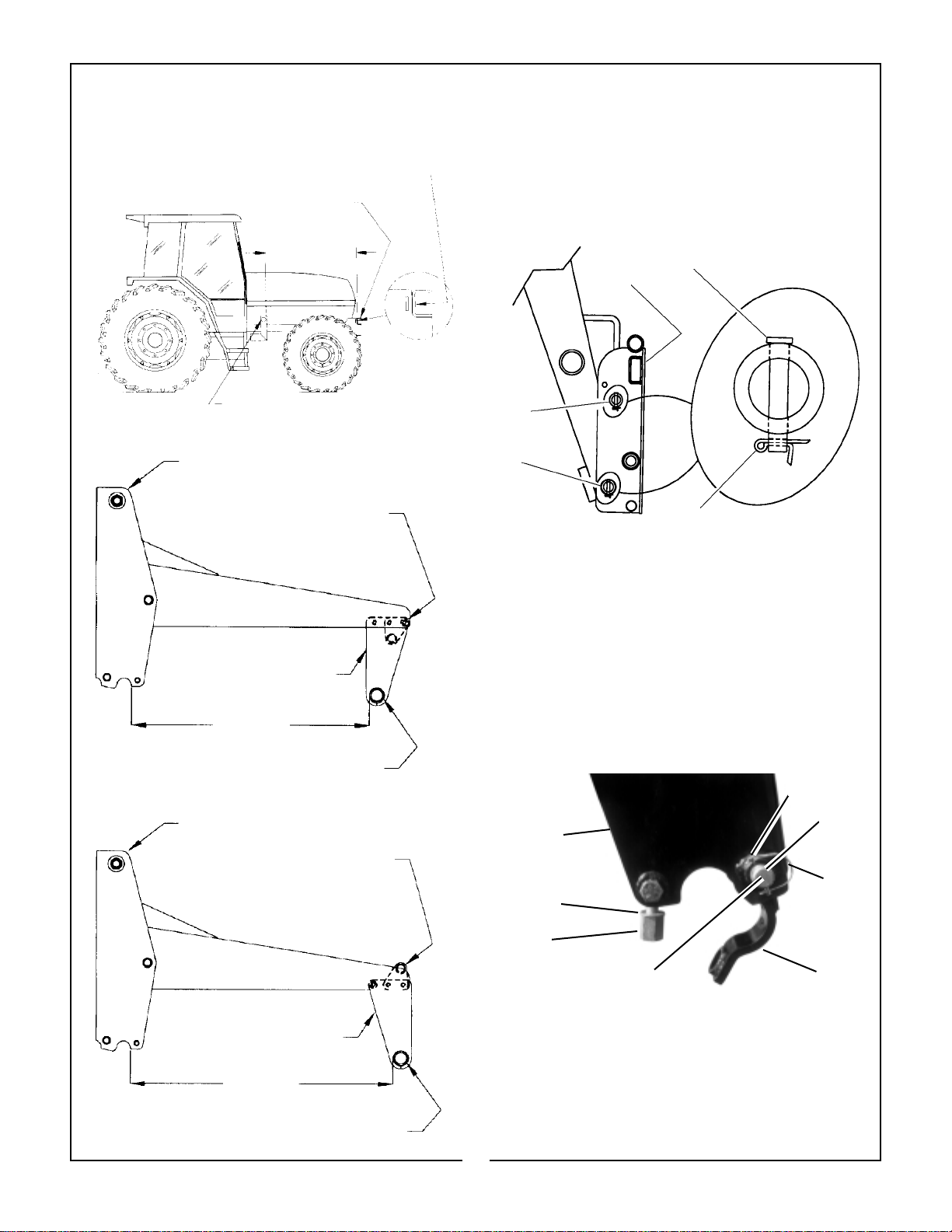
12. SUPER PENETRATOR BALE PROBE ATTACHMENT
IMPORTANT: It is not recommended that loader
be detached from tractor with bale probe
attached. Loaders will park safely, however, bale
probe could be damaged during parking. Always
detach loader with bucket or other Factory
approved attachment attached.
CAUTION
WHEN TRANSPORTING A ROUND BALE,
TILT THE BALE PROBE SLIGHTLY BACK
FROM LEVEL AND CARRY THE LOAD IN A
LOW POSITION.
APPROACH, PENETRATE AND TRANSPORT ROUND BALES AT SLOW SPEED.
DO NOT LIFT ANYTHING WITH PROBE
EXCEPT ROUND BALES.
NEVER RAISE ROUND BALE TO FULL
HEIGHT WITH BALE PROBE ROLLED
BACK AS SERIOUS INJURY OR DEATH
COULD OCCUR.
(1) Super penetrator bale probe.
(2) Tapered sleeve.
(3) Nut, 28mm. Torque super penetrator nut to
515 ft. lb.
Figure 1
TO PREVENT BODILY INJURY, PARK AND
STORE BALE PROBE WITH POINTS
POINTED AGAINST BALE, BUILDING OR
OTHER STABLE OBJECT.
IMPORTANT!
THIS SPEAR IS A HIGH STRENGTH ALLOYDROP FORGED STEEL AND SHOULD NOT BE
WELDED OR HEAT TREATED.
IMPORTANT: Maximum load limit on super penetrator bale probe is 2,200 pounds.
INSTALLATION INSTRUCTIONS
IMPORTANT: Refer to pages 29 & 30 for instruc-
tions concerning Installing Attachment to Quick
Draw Latch Attach.
IMPORTANT: Refer to page 31 for instructions
concerning Removing Attachment from Quick
Draw Latch Attach.
Install bale probe into tapered sleeve and secure
with 28mm nut. Torque super penetrator nut to 515
ft. lb. Refer to Figure 1. Failure to follow these
instructions could cause damage to probe and void
your warranty.
2,200 lb Capacity
OPERATING INSTRUCTIONS
With bale probe attachment level with ground, slowly
probe bale slightly above center. Refer to Figure 2.
Figure 2
With all three bale probes completely engaged into
bale, tilt the bale probe attachment slightly back
from level and transport the load in a low position.
33
Page 36

13. DOZER ATTACHMENT
CAUTION
TO HELP PREVENT BODILY INJURY,
ALWAYS PARK AND STORE DOZER
ATTACHMENT WITH PARKING STANDS IN
PARKED POSITION.
IMPORTANT: Do not park loader with dozer
attachment attached. Always detach loader with
bucket or other factory approved attachment
attached.
INSTALLATION INSTRUCTIONS
IMPORTANT: Refer to pages 29 & 30 for instruc-
tions concerning Installing Attachment to Quick
Draw Latch Attach.
IMPORTANT: Refer to page 31 for instructions
concerning Removing Attachment from Quick
Draw Latch Attach.
A straight dozer is available in 84 inch and 96 inch
widths.
OPERATING INSTRUCTIONS FOR
DISMOUNTING DOZER FROM LOADER
Remove parking stands from stored position.
Position parking stands in parked position.
Disconnect from quick draw latch attach as shown
on page 31. Figure 1 shows dozer attachment with
parking stands in parked position. Refer to Figure 1.
14. MANURE FORK ATTACHMENT
INSTALLATION INSTRUCTIONS
IMPORTANT: Refer to pages 29 & 30 for instruc-
tions concerning Installing Attachment to Quick
Draw Latch Attach.
IMPORTANT: Refer to page 31 for instructions
concerning Removing Attachment from Quick
Draw Latch Attach.
A manure fork is available in a 72" width. The
manure fork utilizes 10 each of 1-1/2" x 1" x 33"
tines. Refer to Figure 1.
Figure 1
(1) Parked position
(2) Storage position
(3) Adjustable skid
Install tines to manure fork using hardware included.
Position plow bolt head on underside of manure fork.
Refer to Figure 2.
Figure 1
Figure 2
(1) Manure fork assembly.
(2) Manure fork tine.
(3) Plow bolt 3/8"-16NC x 3" Grade 5.
(4) Flatwasher, 3/8".
(5) Hex nut 3/8"-16NC 2 way lock.
34
Page 37

15. PALLET FORK ATTACHMENT
CAUTION
FORK TINES MUST BE ADJUSTED OUTWARD AND LOCKED BEHIND PARKING
ANGLES BEFORE PARKING LOADER.
NEVER OPERATE PALLET FORKS WITHOUT GUARD ASSEMBLY INSTALLED.
WARNING
TO AVOID SERIOUS INJURY OR DEATH:
★ NEVER LIFT LARGE ROUND HAY
BALES OR OTHER LOADS ON THE
FORK LIFT ATTACHMENT THAT
COULD ROLL BACK ONTO TRACTOR
OPERATOR AREA.
★ NEVER USE FORK LIFT ATTACHMENT
TO LIFT OR SUPPORT PEOPLE.
★ TRANSPORT LOADS LOW AND SLOW.
★ AVOID CONTACT WITH POWER LINES.
IMPORTANT: When parking loader with pallet
fork attached, fork tines must be adjusted outward and locked behind parking angles before
parking loader. Refer to Figure 1.
INSTALLATION INSTRUCTIONS
IMPORTANT: Refer to pages 29 & 30 for instruc-
tions concerning Installing Attachment to Quick
Draw Latch Attach.
IMPORTANT: Refer to page 31 for instructions
concerning Removing Attachment from Quick
Draw Latch Attach.
OPERATING INSTRUCTIONS
The pallet fork attachment has two tines, 44" long,
and adjustable from 12" to 50" in width. The operator must keep the load centered and as far back on
the forks as possible. Operator must always keep
load level. Carry the load low and at a slow speed.
Figure 1
PARKING ANGLES
35
Page 38

16. GRAPPLE ATTACHMENT
INSTALLATION INSTRUCTIONS
IMPORTANT: Refer to pages 29 & 30 for instruc-
tions concerning Installing Attachment to Quick
Draw Latch Attach.
IMPORTANT: Refer to page 31 for instructions
concerning Removing Attachment from Quick
Draw Latch Attach.
A four tine, two cylinder grapple is available to fit
3860 QT bucket widths of 72, 84, 96 and 102 inches.
The bucket grapple is useful for picking up loose hay
or roughage out of stacks, stacking and transporting
hay bales, carrying silage, and cleaning up brush.
Refer to Figure 1.
Install right and left hand grapple pedestal to bucket
back using 5/8" x 5-1/2" carriage bolts, flatwashers,
and nuts. Install pedestal support using 1/2" x 5-1/2"
bolts, flatwashers, and nuts. DO NOT TIGHTEN.
Refer to Figure 2.
Figure 1
NOTE: Optional extended length grapple tines
are available on some grapple/bucket configurations. Contact Factory for further information.
Figure 2
If your bucket has not been pre-drilled at the factory,
then you must mark center line of pedestal support
slots and center punch. Remove pedestal assembly
and drill 9/16" holes 4 places. Reinstall pedestals.
Refer to Figure 3.
Figure 3
36
Page 39

Install bar supports and attach using 1/2" x 3-1/2"
bolts, flatwashers, and nuts. Refer to Figure 4.
Figure 4
Install grapple swing arm assembly to pedestal using
1-5/16" x 6-5/8" pins. Install grapple cylinders to
grapple pedestals using 1-1/8" x 6-1/2" pins. Install
grapple cylinders to swing arm using 1-1/8" x 4-1/2"
pins. Secure all pins using clevis pins and cotters.
Install 90° fittings into cylinder ports and rotate into
position shown. Refer to Figures 5 & 6.
Figure 6
Install grapple tines to swing arm using 3/4" x 2-1/2"
bolts and locknuts, 8 places. Refer to Figure 7.
Figure 5
Figure 7
37
Page 40

QUICK DRAW BUCKET ONLY: Loosely secure
plastic hose clamp and bar support with 3/8" flatwasher and nylon lock nut to 3/8" stud located on
back side of bucket.
Locate center top of bucket and measure right 10
inches. Locate quick coupler mount on bucket at this
point. Center punch and drill 7/16" diameter hole
through top box section of bucket. Refer to Figure 9
and to Figure 6, page 37.
IMPORTANT: Grapple kit contains one each of
3/4"-16 O-ring boss male and female quick coupler. Third cylinder tube kit contains one each of
1/2"-14 NPT male and female quick coupler.
Identify quick coupler and fitting ends before
installing quick couplers.
Install four hoses between cylinder 90° fittings and
bulkhead tee fittings. Guide left hand hoses under
plastic hose clamp and then tighten bolt. Refer to
Figure 11, page 39.
IMPORTANT: Do not over tighten hose clamp
hardware. Only tighten hardware enough to
clamp hoses snugly. Tighten all other grapple
bolts and fittings using Torque Chart, page 43.
Install hoses and fittings from grapple to loader
using third cylinder tube kit. Connect hoses so that
grapple operates as shown below. Refer to Figure 9.
Lift Cylinder Circuit
Figure 8
(1) Bucket.
(3) Quick coupler mount.
(4) Center punch and drill 7/16" hole.
Install two bulkhead straight fittings to quick coupler
mount using bulkhead nuts. Install o-ring to top end of
bulkhead fitting (if not already installed by factory).
Install 3/4"-16 O-Ring Boss male and female quick
couplers to top o-ring side of bulkhead fittings. Install
JIC tee fittings to other side of bulkhead fittings. Refer
to Figure 11, page 39. Secure quick coupler mount to
bucket using 3/8"-16NC x 3-1/2" bolt, lockwasher and
nylon lock nut. Refer to Figure 6, page 37.
Pull the handle
back to raise unit
Pull the handle
back to roll
back attachment
3rd Cylinder (optional) Circuit
Pull the handle
back to open
assembly
Push the handle
forward to lower unit
Push the handle
forward to
dump attachment
Push the handle
forward to close
assembly
Push handle full forward
to activate float position
Figure 9
OPERATING INSTRUCTIONS
When operating the loader with the grapple attachment, always remove the upper level of the stack
first and approach the stack with the bucket level.
The upper grapple teeth must be in the maximum
open position. Never ram the grapple into material to
be loaded to gain the desired depth. Close the upper
grapple assembly only far enough to hold the material in place.
38
Page 41

Figure 10
Ref. Qty. Description
1 2 Grapple Cylinder 2-1/2"
2 4 Fitting, 90° NPTF 1/2" x ORBM 3/4"
3 4 Clevis pin 5/16" x 2" Heat Treated
for use on 1-1/8" pins
2 Clevis pin 3/8" x 2-1/4"
for use on 1-5/16" pins.
4 6 Cotter Pin 1/8" x 1"
5 1 Hose 3/8" x 47.72" Top Left
6 1 Hose 3/8" x 27.48" Top Right
7 1 Hose 3/8" x 42.73" Bottom Left
8 1 Hose 3/8" x 22.98" Bottom Right
9 1 Quick Coupler Mount
10 1 Hex Bolt 3/8"-16NC x 3-1/2" Grade 5
11 2 Flatwasher 3/8"
Ref. Qty. Description
12 2 Hex Nut 3/8" Nylon Lock
13 1 Hex Bolt 3/8"-16NC x 1-3/4"
Pin On Bucket only, or
1 Weld-on Stud
Quick Draw Bucket only.
14 1 Hose Clamp Plastic 5/8 x 5/8
15 1 Hose Bar Support 3/16" x 1" x 2-1/2"
16 1 Quick Coupler Male ORBF 3/4"
17 1 Quick Coupler Female ORBF 3/4"
18 1 Quick Coupler Dust Plug
19 2 Bulkhead O-Ring 3/4"
20 2 Fitting Str. Bulkhead JIC M 3/4"-16
21 2 Bulkhead Nut 3/4"-16
22 2 Fitting Tee JIC M-M-F 3/4"-16
39
Page 42

NOTICE
SUPPLEMENTAL INSTRUCTIONS
FOR FORD GENESIS SPECIAL
Refer to Form BHF 1820 Packing List and Installation Instructions includ-
ed with your BHF 82356 Mounting Kit for detailed Operation Instructions
specific for this Loader.
40
Page 43

SAFETY DECALS
DANGER
LIVE
WIRES
OVERHEAD
33792
To promote safe operation, Bush Hog supplies safety decals on all products manufactured. Because damages
can occur to safety decals either through shipment, use or reconditioning, Bush Hog will, upon request, provide
safety decals for any of our products in the field at no charge. Contact your authorized Bush Hog dealer for
more information.
REAR VIEW OF
SUBFRAME
Decals 25H46070, 25H46071, 25H46010
and 25H46012 are located on the left side of
the subframe. Other decals are located on
attachments (Bucket, Fork Lift, Bale Spear).
➔➔➔
25H46070
25H46071
25H46012
25H46010
50020705
41
Page 44

DECALS CONTINUED
CAUTION
1. USE ONLY FACTORY SUPPLIED CLEVIS AND MOUNTING HARDWARE WHEN
ATTACHING TO CLEVIS MOUNTING POINT OF BUCKET.
2. MAXIMUM LOAD LIMIT ON FACTORY CLEVIS AND CLEVIS MOUNTING POINT IS
6500 POUNDS.
3. NEVER TOW ANY POINT OF THE LOADER WITH A CHAIN, ROPE, OR CABLE.
4. DO NOT APPLY TRACTOR PULL OR PUSH FORCE TO THIS CLEVIS MOUNTING
POINT. APPLY ONLY LOADER HYDRAULIC LIFT OR ROLLBACK CAPACITY TO
THIS CLEVIS MOUNTING POINT. 41077
50020844
CAUTION
TO HELP PREVENT BODILY INJURY,
ALWAYS PARK AND STORE DOZER
ATTACHMENT WITH PARKING STANDS
IN PARKED POSITION.
36464
50020800
50021178
42
25H4926725H49268
Page 45

Wrench
Size “A”
AMERICAN
Bolt Head Markings
SAE Grade 2
(No Dashes)
SAE Grade 5
(3 Dashes)
SAE Grade 8
(6 Dashes)
TORQUE SPECIFICATIONS
Proper toque for American fasteners used on Bush Hog equipment.
Recommended Torque in Foot Pounds (Newton Meters).*
BOLT DIAMETER
Bolt
Diameter “B”
WRENCH (IN.) “B” AND SAE SAE SAE
SIZE (IN.) “A” THREAD SIZE GRADE 2 GRADE 5 GRADE 8
7/16 1/4 - 2O UNC 6 (7) 8 (11) 12 (16)
7/16 1/4 - 28 UNF 6 (8) 10 (13) 14 (18)
1/2 5/16 - 18 UNC 11 (15) 17 (23) 25 (33)
1/2 5/16 - 24 UNF 13 (17) 19 (26) 27 (37)
9/16 3/8 - 16 UNC 20 (27) 31 (42) 44 (60)
9/16 3/8 - 24 UNF 23 (31) 35 (47) 49 (66)
5/8 7/16 - 14 UNC 32 (43) 49 (66) 70 (95)
5/8 7/16 - 20 UNF 36 (49) 55 (75) 78 (106)
3/4 1/2 - 13 UNC 49 (66) 76 (103) 106 (144)
3/4 1/2 - 20 UNF 55 (75) 85 (115) 120 (163)
7/8 9/16 - 12 UNC 70 (95) 109 (148) 153 (207)
7/8 9/16 - 18 UNF 79 (107) 122 (165) 172 (233)
15/16 5/8 - 11 UNC 97 (131) 150 (203) 212 (287)
15/16 5/8 - 18 UNF 110 (149) 170 (230) 240 (325)
1-1/8 3/4 - 10 UNC 144 (195) 266 (360) 376 (509)
1-1/8 3/4 - 16 UNF 192 (260) 297 (402) 420 (569)
1-5/16 7/8 - 9 UNC 166 (225) 430 (583) 606 (821)
1-5/16 7/8 - 14 UNF 184 (249) 474 (642) 668 (905)
1-1/2 1 - 8 UNC 250 (339) 644 (873) 909 (1232)
1-1/2 1 - 12 UNF 274 (371) 705 (955) 995 (1348)
1-1/2 1 - 14 UNF 280 (379) 721 (977) 1019 (1381)
1-11/16 1-1/8 - 7 UNC 354 (480) 795 (1077) 1288(1745)
1-11/16 1-1/8 - 12 UNF 397 (538) 890 (1206) 1444 (1957)
1-7/8 1-1/4 - 7 UNC 500 (678) 1120 (1518) 1817 (2462)
1-7/8 1-1/4 - 12 UNF 553 (749) 1241 (1682) 2013 (2728)
2-1/16 1-3/8 - 6 UNC 655 (887) 1470 (1992) 2382 (3228)
2-1/16 1-3/8 - 12 UNF 746 (1011) 1672 (2266) 2712 (3675)
2-1/4 1-1/2 - 6 UNC 870 (1179) 1950 (2642) 3161 (4283)
2-1/4 1-1/2 - 12 UNF 979 (1327) 2194 (2973) 3557 (4820)
Proper torque for metric fasteners used on Bush Hog equipment.
METRIC
Wrench
Size “A”
Numbers appearing on bolt heads
indicate ASTM class.
8.8
Bolt
Diameter “B”
*Use 75% of the specified torque value for plated
fasteners. Use 85% of the specified torque
values for lubricated fasteners.
Recommended torque in foot pounds (newton Meters).*
WRENCH BOLT
SIZE DIA. ASTM ASTM ASTM ASTM
(mm) “A” (mm) “B” 4.6 8.8 9.8 10.9
8 5 1.8 (2.4) 5.1 (6.9) 6.5 (8.8)
10 6 3 (4) 8.7 (12) 11.1 (15)
13 8 7.3 (10) 21.1 (29) 27 (37)
16 10 14.5 (20) 42 (57) 53 (72)
18 12 25 (34) 74 (100) 73 (99) 93 (126)
21 14 40 (54) 118 (160) 116 (157) 148 (201)
24 16 62 (84) 167 (226) 181 (245) 230 (312)
30 20 122 (165) 325 (440) 449 (608)
33 22 443 (600) 611 (828)
36 24 211 (286) 563 (763) 778 (1054)
41 27 821 (1112) 1138 (1542)
46 30 418 (566) 1119 (1516) 1547 (2096)
43
Page 46

P.O. Box 1039llSelma, AL 36702-1039
Telephone (334) 874-2700
ll
www.bushhog.com
 Loading...