


 Loading...
CC 9060 Music
Index
Introductory information |
2 |
||
|
|
|
|
|
1. |
General |
2 |
2. |
Security guidelines |
2 |
|
Installation of the hands-free car kit |
4 |
||
|
3. |
Scope of supply |
4 |
4. |
Positioning and mounting |
6 |
|
5. |
Connections on the electronics box |
9 |
|
Operating guidelines |
15 |
||
|
|
|
|
|
6. |
Using the hands-free car kit for the first time |
15 |
|
7. Handling possibilities |
16 |
|
8. |
Voice control |
16 |
|
|
9. Handling via Touch screen |
17 |
|
|
10. Establishing a Bluetooth connection |
18 |
|
|
11. Menu navigation |
19 |
|
|
12. Accepting, making, ending calls |
40 |
|
|
13. Transferring Calls |
41 |
|
|
14. Conference Mode |
42 |
|
Further Information |
43 |
||
|
15. Service |
43 |
|
|
16. Appropriate use of this system |
44 |
|
|
17. Approvals and declaration of conformity |
44 |
|

2 |
Introductory information |
1. General
Dear customer,
Congratulations on purchasing a BURY hands-free car kit. You have chosen a high quality product that is extremely easy to use.
Please read the operating manual carefully so that you can fully enjoy your BURY hands-free car kit. If you have any further questions concerning installation or operation of your car kit, please contact your dealer. He will be happy to give you reliable advice.
You can also contact our hotline. Our phone and fax numbers are listed in the chapter Service at the end of the operating instructions.
Have a good trip!
2. Security guidelines
Installation - who should do it
We recommend to let a specialised workshop perform the installation. Only professionals will observe the installation requirements of the automotive manufacturer (VAS 1978) correctly.
Power supply
This system has been designed for the use in vehicles with an on-board supply system of 12 volts (passenger car). If you intend to install the device in a vehicle with an on-board supply system of 24 volts (lorry), please use a voltage converter. If you have queries regarding this subject, please contact our hotline.
Position, volume
Install the components of the device in the vehicle so that your field of vision is not impaired and the components are not mounted in the impact zone of the passenger compartment or in the airbag inflation zones. The removal of coverings (with and without airbags) or components of the dashboard requires – in some cases – special tools and special knowledge.

3
Intended use
We shall not be liable for damages or malfunctions due to improper use of the hands-free system. Therefore, do not expose the device to moisture, extreme temperatures or shocks and carefully follow the procedure described in the installation and operating guidelines.
Use while driving
Operate the system only when the situation allows it and when you do not endanger, harm, constrain, or annoy other road users. The volume of the device has to be set in a way that exterior noise is still audible.
Faults
Do not commission the device if you detect or assume a defect. In this case, contact a Bury specialised dealer or our hotline. Improper repair efforts can be dangerous for you. Therefore, only skilled personnel may perform inspections.
Important:
XXThe driver is ultimately responsible for the safe operation and control of their vehicle at all times. You should never use a hand held phone, including sending or reading text or picture messages, while driving.
XXResearch indicates that there is a risk to safety when the driver of a motor vehicle is distracted and using a mobile phone while driving can be a distraction.
XXThe manufacturer strongly recommends that you use a hands-free solution when driving.

4Installation of the hands-free car kit
3.Scope of supply
SYS9
PHONE |
OUT |
|
MIC
LINE |
OUT |
|
/iPHONE iPOD
RC
DISP
8 |
9 |
molex

5
The hands-free car kit (HFCK) is supplied with different combinations of components, depending on the sales regions (countries). The operating manual refers to all versions.
Description of the components:
1)Electronics box
2)Monitor, holder and installation pad
3)Mounting accessories
Fixing screws for electronics box, rider, screws for the holder and rubber cover, adhesive tape, cleaning cloth
4)Microphone
5)Printed installation and operating manual, Quick user guide
6)Case
7)iPod/iPhone cable
8)Vehicle Interface Lead (ISO)
9)Power supply cable with fuses
Version 1:
- with Vehicle Interface Lead (ISO)
Version 2:
-without Vehicle Interface Lead (ISO)
-with power supply cable
Note:
XXIf certain components are added or omitted you will receive the corresponding information on a separate enclosure.

6 Installation of the hands-free car kit
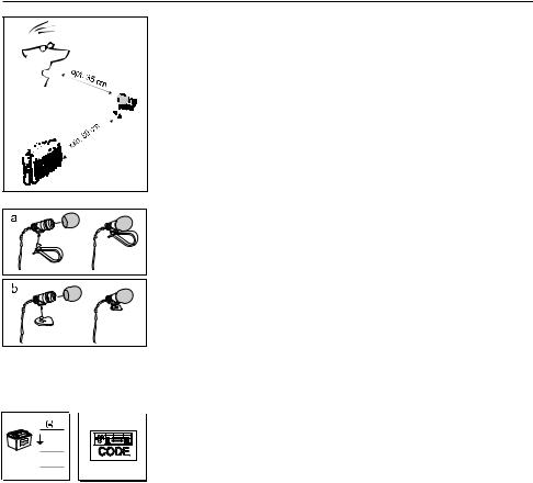
4. Positioning and mounting
Step 1:
First of all, please choose the most convenient position for the attached monitor on the holder and the installation pad in your vehicle by checking different positions in the vehicle.
If you would like to use the device during your journey, positioning it in the front area on the driver’s side is advisable. Sit in the vehicle and check whether you can reach the device without difficulty.
After having found a suitable position for the monitor in the vehicle you can now mount / attach the installation pad / the holder with or without the installation pad accordingly. Please use a cleaning cloth for degreasing the surfaces to which you want to attach the corresponding adhesive surface of either the holder or the installation pad.
The end of the cable with the small Molex connector on the holder is ideally suited for placing through small openings in the dashboard area. This facilitates a practically invisible installation of the cable. Take the length of the cable into account and make sure that it is of sufficient length to reach the intended location of the electronics box.
Important:
XXWhen positioning the monitor please take care that the monitor does not impair the view onto the road, that it will not be installed in the impact zone of the passenger compartment (amongst others in the airbag inflation zones) and that the cable may be laid without any problems.
XXThe installation pad can be affixed just once, removing could damage the adhesive area. In case of high variations in temperatures - depending on the structure and the features - decolourisations of the surfaces can occur during the subsequent utilization.
XXPlease avoid direct sunlight on the monitor or high internal temperatures, which can be rapidly reached in parked vehicles. In such cases, remove the monitor of the handsfree car kit from the cradle and put it in the car glove pocket or glove box for instance.

7
Example of installation 1: |
|
1 |
2 |
|
5 |
3 |
4 |
|
6 |
Example of installation 2: |
|
|
1 |
2 |
3 |
|
4 |
5 |
6 |
8 Installation of the hands-free car kit
Step 2:
Depending on the vehicle type and its equipment (e.g. airbags), it is reasonable to install the microphone either at the A-pillar, at the sun shield or at the roof interior. For details about the equipment features please refer to the vehicle documents.
Step 3:
Remove or loosen up cladding and covers to be able to install all of the cables in the vehicle as comfortably as possible. Please lay the cables in a way that they do not lie/hang unsecured in the vehicle and that they may not influence the conducting of the vehicle. When laying a cable, please take care that it is not under traction stress but that it has some tolerance. Avoid crushing the cable as damages of the insulation can be caused by friction/rubbing.
Step 4:
Install the electronics box at a convenient place in the vehicle. This can e.g. be behind the radio, in the glove box, or in the centre console. Please mind that you can access the connections of the box without difficulty. It is possible that you will have to connect the components before attaching the electronics box, if it isn’t possible to do this afterwards due to a lack of space. A description of the connections is provided in the next section.
Before connecting the components to the electronics box you should branch off the battery for safety reasons. In doing so, take into account that there might be a radio coding (confer radio manual).
Important:
XXPlease install the electronics box behind a cover or somewhere you can only reach by opening or unfastening a protective cover / a cover. The terminal box must not hang loosely in the vehicle.
9
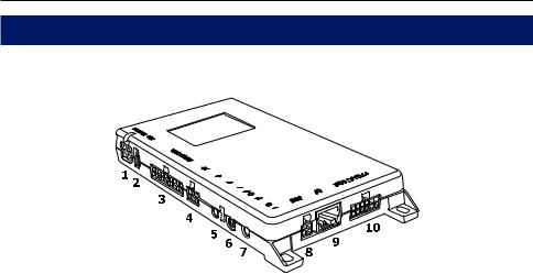
5. Connections on the electronics box
The additional components of the HFCK are connected to the electronics box. The following connections are provided:
SYS9
PHONE |
OUT |
|
MIC
LINE |
OUT |
|
/iPHONE iPOD
RC
DISP
Connection options:
1Power supply / Mute
2Ignition
3Vehicle Interface Lead (ISO)
4basePlate System 9 adapted for CC 9060
5Phone-OUT (Jack 3,5 mono)
6Microphone input
7LINE-OUT (Jack 3,5mm stereo)
8Monitor / Touch screen
9Accessories / Remote control
10iPod/iPhone Connection
Connection 1 - Power supply / Mute
Version 1:
This connection is not used with version 1. Refer to connection 3.
Version 2:
The power supply of the HFCK is established via a 4-core cable (scope of supply no. 9). Connect the black (clamp 31 – minus), the red (clamp 30 – steady plus) and the blue cable (clamp 15 – ignition plus) to the power supply of your radio (where required via the cigarette lighter or the fuse box). After connection to the counterpart, the yellow cable provides for radio muting during a phone conversation. Please connect the white Molex connector with connection 1.
If you connect additional adapter cables or accessories to connections 5 and 7 to play back music and for voice feedback, then when you subsequently activate the HFCK, you will have to select Option 3 in the Settings -> Audio -> Installation menu.
10 Installation of the hands-free car kit
Attention:
XXIf you also connect the blue cable to clamp 30 (steady positive), the HFCK will be permanently supplied with power. If the vehicle is not running for a longer period, this could lead to a discharge of the car battery.
XXIf you deviate from the specified connection descriptions it may be the case that certain functions on the HFCK (e.g. the on-call duty) will not function correctly.
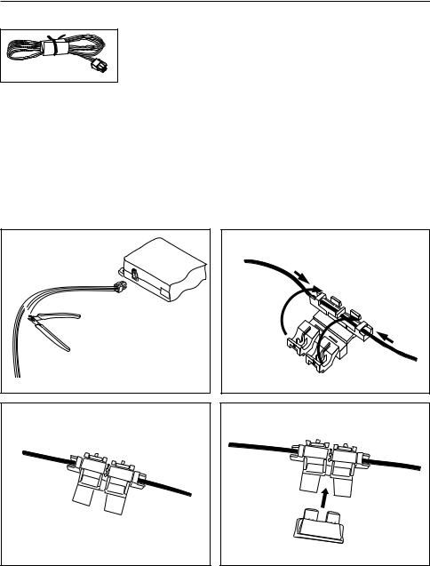
Installation instructions for the fuses
Please cut through the red, the black and the blue cable by means of a wire cutter or scissors. Now insert the two endings of the red cable resulting from the cut into one of the binders, then close it. If you hear two clicking noises, the clamp snapped in properly. Now insert one of the fuses and then repeat the procedure with the other cables.
11
Connection 2 - Ignition
Version 1:
See connection 3.
Version 2:
This connection is not used with version 2.
Connection 3 - Vehicle Interface Lead (ISO) Version 1:
The power supply to the HFCK and functions such as the muting of the car radio as well as the voice feedback and playback of music on the car speakers are guaranteed through the ISO cable harness from Elan.
**********************************************************
Elan Europe is a leading manufacturer of audio integration products and have developed and manufactured a comprehensive vehicle specific cable harness range that enables the installer to connect this HFCK straight into the vehicle audio system without the need to use vehicle converter cables.
This cable harness range has been designed to provide the installer with a high quality integration product that is quick and easy to install providing the perfect Plug & Play installation.
BURY Technologies in partnership with Elan Europe can now offer this comprehensive vehicle harness range to this HFCK customers to compliment their installation.
The full product range and vehicle database is available on our website: www.elan-eu.com/bury
Contact details: Elan Europe
11-14 Kempton Road Keytec 7 Business Park Pershore Worcestershire
United Kingdom WR10 2TA
Website: www.elan-eu.com Sales: sales@elan-eu.com
Technical Support: technical@elan-eu.com
**********************************************************
m |
ol |
ex |
12 Installation of the hands-free car kit
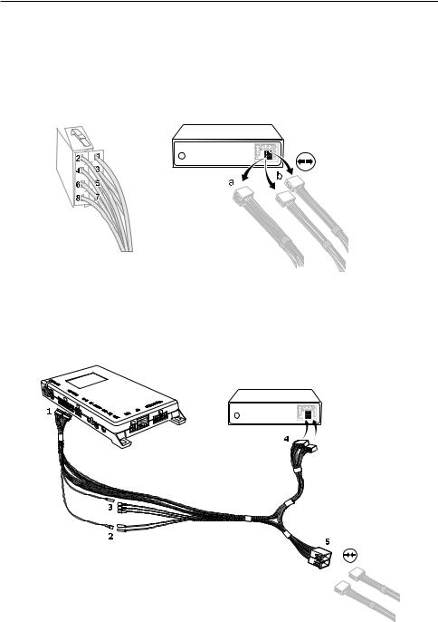
The pin-assignment of the ISO-connectors can vary depending on the type of vehicle / car radio. To prevent damage from occurring, before using the ISO cable harness, make sure that the assignment is correct. Information is provided about this in the description of the car radio.
Remove the (a) or the (b) ISO-connector at the back of the radio. Connect this and/or these connectors with the matching jack (5) on the ISO-cable harness. Now connect the connector (4) from the ISOcable tree with the radio again.
Starting from the black 20-pole Molex connector (connector 1, which is plugged into connection 3 on the electronics box), you will find one yellow (radio muting) and one red (steady plus) cable with plug connectors. Please plug the red cable that comes from the ISO-connectors to the red cable (2) which also contains the steady positive signal (clamp 30). If available, check using a Multimeter to see whether any voltage is present on the cable.
SYS9
PHONE |
OUT |
|
MIC
LINE |
OUT |
|
/iPHONE iPOD
RC
DISP
a
b 

13
The second red cable coming from the ISO-connectors contains the ignition plus signal (clamp 15). Please connect this with the separate blue cable, whose black Molex connector you subsequently plug into connection 2 on the electronics box. If you are not able to tap the ignition signal via the second red cable, then please check in your vehicle documents and find a different cable which carries this signal.
Three other cables are positioned opposite to the single yellow cable (3) for the radio muting. You can also find the correct cable here via Multimeter. If either this or another measuring tool isn’t available, you can use a test, e.g. through activating the voice control, to ascertain as to whether the radio is muted or not. You may find the pin assignment for the ‘mute’ signal in the radio handbook.
Using the ISO-cable harness, you are able to assign the playback of music and voice feedback during a telephone call to the vehicle’s speakers. With incoming telephone calls, the playback of music (by the HFCK or the car radio) is automatically interrupted. Select the Option 1 in the menu
Settings -> Audio -> Installation when the HFCK is activated.
If you use the ISO cable harness and an additional adapter cable at the LINE OUT output (connection 7) of the HFCK, then Option 2 is to be selected in the menu Settings -> Audio -> Installation when the HFCK is activated. This installation option is available if the car radio which is installed in the vehicle has a LINE-IN input but no PHONE-IN input and/or does not have its own radio muting.
Attention:
XXThe factory setting is Option 1.
XXIf you also connect the blue cable to clamp 30 (steady positive), the HFCK will be permanently supplied with power. If the vehicle is not running for a longer period, this could lead to a discharge of the car battery.
XXIf you deviate from the stated description of the connections, it is possible that certain functions on the HFCK (e.g. the on-call duty) will not function correctly.
Version 2:
This connection is not used with version 2.

14 Installation of the hands-free car kit
Connection 4 - Connection for System 9 basePlate compatible with the CC 9060
This is where you connect the basePlate for the System 9. This basePlate is specially adapted for the electronics box of the HFCK. The basePlate is supplied with power via the electronics box. You can charge your mobile phone here and also leave it here for safekeeping.
Connection 5 - Phone-OUT
If you do not use the ISO-cable harness to play back the voice output of the HFCK on the vehicle’s speakers, then you can connect, for example, a separate BURY speaker or another adapted cable here. The connection on the HFCK is suitable for a 3.5 mm sized mono jack. Depending on the type of car radio, the other connection is to be selected separately.
Connection 6 - Microphone input
This is where you plug in the microphone jack. After connection 3 has already been occupied use the rider. This ensures that neither of the jacks is able to loosen as a result of vibrations.
Connection 7 - LINE-OUT
If you do not use the ISO-cable harness to play back the voice output of the HFCK on the vehicle’s speakers, then you can connect, for example, a different adapter cable here. The connection on the HFCK is suitable for a 3.5 mm sized stereo jack. Depending on the type of car radio, the other connection is to be selected separately.
Connection 8 - Monitor
Please plug the 9 pole plug of the monitor connection cable into this jack. Tighten at least one of the two fixing screws hand-tight so that this plug cannot become unplugged as a result of vibrations.
Connection 9 - Connection for additional accessories
Not currently available.
Connection 10 - for Apple iPod/iPhone
Please plug in the supplied cable (scope of supply no. 7) here. You can connect an Apple product at the other end of it via the Apple Dock Connector in order to play back music.
Loading...