


Burr Brown Corporation DCP010512DBP-U, DCP010512DBP, DCP010512BP-U, DCP010512BP, DCP010505DBP-U Datasheet
...
®
DCP01


DCP01

For most current data sheet and other product information, visit www.burr-brown.com
DCP01B
Series
Miniature, 1W Isolated
UNREGULATED DC/DC CONVERTERS
FEATURES |
APPLICATIONS |
|
● UP TO 85% EFFICIENCY |
● POINT-OF-USE POWER CONVERSION |
|
● THERMAL PROTECTION |
● GROUND LOOP ELIMINATION |
|
● DEVICE-TO-DEVICE SYNCHRONIZATION |
● DATA ACQUISITION |
|
● SHORT CIRCUIT PROTECTION |
● INDUSTRIAL CONTROL AND |
|
● EN55022 CLASS B EMC PERFORMANCE |
INSTRUMENTATION |
|
● TEST EQUIPMENT |
||
● UL1950 RECOGNIZED COMPONENT |
||
|
||
● JEDEC PDIP-14 AND GULL-WING PACKAGES |
DESCRIPTION |
|
|
||
|
The DCP01B series is a family of 1W, unregulated, |
|
|
isolated DC/DC converters. Requiring a minimum of |
|
|
external components and including on-chip device |
|
|
protection, the DCP01B series provides extra features |
|
|
such as output disable and synchronization of switch- |
|
|
ing frequencies. |
|
|
The use of a highly integrated package design results |
|
|
in highly reliable products with a power density of |
|
|
40W/in3 (2.4W/cm3). This combination of features |
|
|
and small size makes the DCP01B suitable for a wide |
|
|
range of applications. |
SYNCOUT
800kHz |
2 |
|
VOUT |
Oscillator |
Reset |
Power |
|
|
|
0V |
|
|
|
Stage |
|
|
|
|
|
SYNCIN |
Watch-dog/ |
|
|
start-up |
|
|
|
|
PSU |
|
|
|
Thermal |
IBIAS |
|
|
Shutdown |
|
|
VS |
|
|
|
|
Power Controller IC |
|
|
|
|
0V |
|
International Airport Industrial Park • Mailing Address: PO Box 11400, Tucson, AZ 85734 • Street Address: 6730 S. Tucson Blvd., Tucson, AZ 85706 • Tel: (520) 746-1111 Twx: 910-952-1111 • Internet: http://www.burr-brown.com/ • Cable: BBRCORP • Telex: 066-6491 • FAX: (520) 889-1510 •mmediateI Product Info: (800) 548-6132

 ®
®
© 2000 Burr-Brown Corporation |
1 |
DCP01B |
PDS-1586B |
Printed in U.S.A. May, 2000 |
|
|
SPECIFICATIONS
At TA = +25°C, unless otherwise specified.
|
|
|
|
|
|
|
|
|
|
|
|
|
|
|
DCP01B SERIES |
|
|
|
|
|
||||
|
|
|
|
|
|
|
|
|
|
|
|
|
|
|
|
|
|
|
|
|
|
|
|
|
PARAMETER |
|
|
|
|
|
|
|
|
|
CONDITIONS |
|
|
MIN |
|
TYP |
|
MAX |
|
|
UNITS |
||||
|
|
|
|
|
|
|
|
|
|
|
|
|
|
|
|
|
|
|
|
|
|
|
|
|
OUTPUT |
|
|
|
|
|
|
|
|
|
|
|
|
|
|
|
|
|
|
|
|
|
|
|
|
Power |
|
|
|
|
|
|
|
|
100% Full Load |
|
|
|
|
0.97 |
|
|
|
|
W |
|
||||
Ripple |
|
|
|
|
|
|
|
O/P Capacitor = 1μF, 50% Load |
|
|
|
20 |
|
|
|
|
mVp-p |
|||||||
Voltage vs Temp |
|
|
|
|
|
|
|
|
|
Room to Cold |
|
|
|
|
0.046 |
|
|
|
|
%/°C |
||||
|
|
|
|
|
|
|
|
|
|
Room to Hot |
|
|
|
|
0.016 |
|
|
|
|
%/°C |
||||
|
|
|
|
|
|
|
|
|
|
|
|
|
|
|
|
|
|
|
|
|
|
|
|
|
INPUT |
|
|
|
|
|
|
|
|
|
|
|
|
|
|
|
|
|
|
|
|
|
|
|
|
Voltage Range on VS |
|
|
|
|
|
|
|
|
|
|
|
|
|
–10 |
|
|
|
|
10 |
|
|
% |
|
|
|
|
|
|
|
|
|
|
|
|
|
|
|
|
|
|
|
|
|
|
|
|
|
|
|
ISOLATION |
|
|
|
|
|
|
|
|
|
|
|
|
|
|
|
|
|
|
|
|
|
|
|
|
Voltage |
|
|
|
|
|
|
|
|
|
1s Flash Test |
|
1 |
|
|
|
|
|
|
|
kVrms |
||||
|
|
|
|
|
|
|
|
|
60s Test, UL1950(1) |
1 |
|
|
|
|
|
|
|
kVrms |
||||||
LINE |
|
|
|
|
|
|
|
|
|
|
|
|
|
|
|
|
|
|
|
|
|
|
|
|
Regulation |
|
|
|
|
|
|
|
|
|
|
|
|
|
|
|
|
1 |
|
|
|
%/1% of VS |
|||
|
|
|
|
|
|
|
|
|
|
|
|
|
|
|
|
|
|
|
|
|
|
|
|
|
SWITCHING/SYNCHRONIZATION |
|
|
|
|
|
|
|
|
|
|
|
|
|
|
|
|
|
|
|
|
|
|||
Oscillator Frequency (fOSC) |
|
|
|
|
|
|
Switching Frequency = fOSC /2 |
|
|
|
800 |
|
|
|
|
kHz |
|
|||||||
Sync Input Low |
|
|
|
|
|
|
|
|
|
|
|
|
|
0 |
|
|
|
|
0.4 |
|
|
V |
|
|
Sync Input Current |
|
|
|
|
|
|
|
|
|
VSYNC = +2V |
|
|
|
|
75 |
|
|
|
|
μA |
|
|||
Disable Time |
|
|
|
|
|
|
|
|
|
|
|
|
|
|
|
|
2 |
|
|
|
|
μs |
|
|
Capacitance Loading on SYNCIN Pin |
|
|
|
|
|
|
|
External |
|
|
|
|
|
|
|
3 |
|
|
pF |
|
||||
RELIABILITY |
|
|
|
|
|
|
|
|
|
|
TA = +55°C |
|
|
|
|
|
|
|
|
|
|
|
|
|
Demonstrated |
|
|
|
|
|
|
|
|
|
|
|
|
|
|
|
|
|
75 |
|
|
FITS |
|
||
|
|
|
|
|
|
|
|
|
|
|
|
|
|
|
|
|
|
|
|
|
|
|
|
|
THERMAL SHUTDOWN |
|
|
|
|
|
|
|
|
|
|
|
|
|
|
|
|
|
|
|
|
|
°C |
|
|
IC Temperature at Shutdown |
|
|
|
|
|
|
|
|
|
|
|
|
|
150 |
|
|
|
|
|
|||||
Shutdown Current |
|
|
|
|
|
|
|
|
|
|
|
|
|
|
|
|
3 |
|
|
|
|
mA |
|
|
|
|
|
|
|
|
|
|
|
|
|
|
|
|
|
|
|
|
|
|
|
|
|
|
|
TEMPERATURE RANGE |
|
|
|
|
|
|
|
|
|
|
|
|
|
|
|
|
|
|
|
|
|
°C |
|
|
Operating |
|
|
|
|
|
|
|
|
|
|
|
|
|
|
–40 |
|
|
|
|
+100 |
|
|
|
|
|
|
|
|
|
|
|
|
|
|
|
|
|
|
|
|
|
|
|
|
|
|
|
||
|
|
INPUT |
|
|
OUTPUT |
|
LOAD |
|
|
NO LOAD |
|
|
|
|
|
BARRIER |
||||||||
|
VOLTAGE (V) |
VOLTAGE (V) |
|
REGULATION (%) |
|
CURRENT (mA) |
|
EFFICIENCY (%) |
CAPACITANCE (pF) |
|||||||||||||||
|
|
|
|
|
|
|
|
|
|
|
|
|
|
|
|
|
|
|
|
|
|
|
|
|
|
|
VS |
|
|
|
VNOM |
|
|
|
|
|
IQ |
|
|
|
|
|
|
CISO |
|
||||
|
|
|
|
|
75% LOAD(2) |
|
10% TO 100% LOAD(3) |
|
0% LOAD |
|
100% LOAD |
V |
= 750V |
RMS |
||||||||||
|
|
|
|
|
|
|
|
|
|
|
|
|
|
|
|
|
|
|
|
|
|
ISO |
|
|
PRODUCT |
MIN |
TYP |
|
MAX |
MIN |
|
TYP |
|
MAX |
|
TYP |
|
MAX |
|
TYP |
|
TYP |
|
|
|
TYP |
|
||
DCP010505B |
4.5 |
5 |
|
5.5 |
4.75 |
|
5 |
|
5.25 |
|
19 |
|
31 |
|
20 |
|
|
80 |
|
|
|
3.6 |
|
|
DCP010505DB |
4.5 |
5 |
|
5.5 |
±4.25 |
|
±5 |
|
±5.75 |
|
18 |
|
32 |
|
22 |
|
|
81 |
|
|
|
3.8 |
|
|
DCP010512B |
4.5 |
5 |
|
5.5 |
11.4 |
|
12 |
|
12.6 |
|
21 |
|
38 |
|
29 |
|
|
85 |
|
|
|
5.1 |
|
|
DCP010512DB |
4.5 |
5 |
|
5.5 |
±11.4 |
|
±12 |
|
±12.6 |
|
19 |
|
37 |
|
40 |
|
|
82 |
|
|
|
4.0 |
|
|
DCP010515B |
4.5 |
5 |
|
5.5 |
14.25 |
|
15 |
|
15.75 |
|
26 |
|
42 |
|
34 |
|
|
82 |
|
|
|
3.8 |
|
|
DCP010515DB |
4.5 |
5 |
|
5.5 |
±14.25 |
|
±15 |
|
±15.75 |
|
19 |
|
41 |
|
42 |
|
|
85 |
|
|
|
4.7 |
|
|
DCP012405B |
21.6 |
24 |
|
26.4 |
4.75 |
|
5 |
|
5.25 |
|
13 |
|
23 |
|
14 |
|
|
77 |
|
|
|
3.8 |
|
|
|
|
|
|
|
|
|
|
|
|
|
|
|
|
|
|
|
|
|
|
|
|
|
|
|
NOTES: (1) During UL1950 recognition tests only. (2) 100% Load Current = 1W/VNOM TYP. (3) Load regulation = (VOUT at 10% Load – VOUT at 100% Load)/VOUT at 75% Load.
ABSOLUTE MAXIMUM RATINGS
Input Voltage: |
|
5V Input Models .................................................................................. |
7V |
24V Input Models .............................................................................. |
29V |
Storage Temperature ...................................................... |
–60°C to +125°C |
Lead Temperature (soldering, 10s) ................................................. |
270°C |
|
|
ORDERING INFORMATION
DCP01 05 05 ( D ) ( B ) ( )
Basic Model Number: 1W Product 
Voltage Input:
5V In
Voltage Output:
5V Out
Dual Output:
Model Revision:
Package Code:
P = PDIP-14
P-U = PDIP-14 Gull-Wing
ELECTROSTATIC DISCHARGE SENSITIVITY
This integrated circuit can be damaged by ESD. Burr-Brown recommends that all integrated circuits be handled with appropriate precautions. Failure to observe proper handling and installation procedures can cause damage.
ESD damage can range from subtle performance degradation to complete device failure. Precision integrated circuits may be more susceptible to damage because very small parametric changes could cause the device not to meet its published specifications.


 ®
®
|
DCP01B |
2 |
|

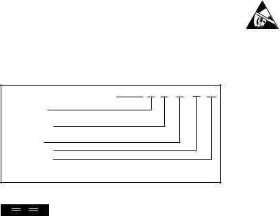
PIN CONFIGURATION (Single-DIP and Gull-Wing) |
PIN CONFIGURATION (Dual-DIP and Gull-Wing) |
|||||||
|
|
|
|
|
|
|
|
|
Top View |
|
|
DIP |
|
Top View |
|
|
DIP |
VS |
1 |
14 |
SYNCIN |
|
VS |
1 |
14 |
SYNCIN |
0V |
2 |
|
|
|
0V |
2 |
|
|
|
|
DCP01B |
|
|
|
|
DCP01DB |
|
0V |
5 |
|
|
|
0V |
5 |
|
|
+VOUT |
6 |
|
|
|
+VOUT |
6 |
|
|
NC |
7 |
8 |
SYNCOUT |
|
–VOUT |
7 |
8 |
SYNCOUT |
|
|
|
|
|
|
|
|
|
PIN DEFINITION (Single-DIP)
PIN # |
PIN NAME |
DESCRIPTION |
|
|
|
1 |
VS |
Voltage Input |
2 |
0V |
Input Side Common |
5 |
0V |
Output Side Common |
6 |
+VOUT |
+Voltage Out |
7 |
NC |
Not Connected |
8 |
SYNCOUT |
Unrectified Transformer Output |
14 |
SYNCIN |
Synchronization Pin |
PIN DEFINITION (Dual-DIP)
PIN # |
PIN NAME |
DESCRIPTION |
|
|
|
1 |
VS |
Voltage Input |
2 |
0V |
Input Side Common |
5 |
0V |
Output Side Common |
6 |
+VOUT |
+Voltage Out |
7 |
–VOUT |
–Voltage Out |
8 |
SYNCOUT |
Unrectified Transformer Output |
14 |
SYNCIN |
Synchronization Pin |
PACKAGE/ORDERING INFORMATION
|
|
PACKAGE |
SPECIFIED |
|
|
|
|
|
DRAWING |
TEMPERATURE |
PACKAGE |
ORDERING |
TRANSPORT |
PRODUCT |
PACKAGE |
NUMBER |
RANGE |
MARKING |
NUMBER(1) |
MEDIA |
Single |
|
|
–40°C to +100°C |
|
|
|
DCP010505BP |
DIP-14 |
010-1 |
DCP010505BP |
DCP010505BP |
Rails |
|
DCP010505BP-U |
DIP-14 Gull-Wing |
010-2 |
–40°C to +100°C |
DCP010505BP-U |
DCP010505BP-U/700 |
Tape and Reel |
DCP010512BP |
DIP-14 |
010-1 |
–40°C to +100°C |
DCP010512BP |
DCP010512BP |
Rails |
DCP010512BP-U |
DIP-14 Gull-Wing |
010-2 |
–40°C to +100°C |
DCP010512BP-U |
DCP010512BP-U/700 |
Tape and Reel |
DCP010515BP |
DIP-14 |
010-1 |
–40°C to +100°C |
DCP010515BP |
DCP010515BP |
Rails |
DCP010515BP-U |
DIP-14 Gull-Wing |
010-2 |
–40°C to +100°C |
DCP010515BP-U |
DCP010515BP-U/700 |
Tape and Reel |
DCP012405BP |
DIP-14 |
010-1 |
–40°C to +100°C |
DCP012405BP |
DCP012405BP |
Rails |
DCP012405BP-U |
DIP-14 Gull-Wing |
010-2 |
–40°C to +100°C |
DCP012405BP-U |
DCP012405BP-U/700 |
Tape and Reel |
Dual |
|
|
–40°C to +100°C |
|
|
|
DCP010505DBP |
DIP-14 |
010-1 |
DCP010505DBP |
DCP010505DBP |
Rails |
|
DCP010505DBP-U |
DIP-14 Gull-Wing |
010-2 |
–40°C to +100°C |
DCP010505DBP-U |
DCP010505DBP-U/700 |
Tape and Reel |
DCP010512DBP |
DIP-14 |
010-1 |
–40°C to +100°C |
DCP010512DBP |
DCP010512DBP |
Rails |
DCP010512DBP-U |
DIP-14 Gull-Wing |
010-2 |
–40°C to +100°C |
DCP010512DBP-U |
DCP010512DBP-U/700 |
Tape and Reel |
DCP010515DBP |
DIP-14 |
010-1 |
–40°C to +100°C |
DCP010515DBP |
DCP010515DBP |
Rails |
DCP010515DBP-U |
DIP-14 Gull-Wing |
010-2 |
–40°C to +100°C |
DCP010515DBP-U |
DCP010515DBP-U/700 |
Tape and Reel |
NOTE: (1) Models with a slash (/) are available only in Tape and Reel in the quantities indicated (e.g., /700 indicates 700 devices per reel). Ordering 700 pieces of “DCP010505BP-U/700” will get a single 700-piece Tape and Reel.
The information provided herein is believed to be reliable; however, BURR-BROWN assumes no responsibility for inaccuracies or omissions. BURR-BROWN assumes no responsibility for the use of this information, and all use of such information shall be entirely at the user’s own risk. Prices and specifications are subject to change without notice. No patent rights or licenses to any of the circuits described herein are implied or granted to any third party. BURR-BROWN does not authorize or warrant any BURR-BROWN product for use in life support devices and/or systems.


 ®
®
3 |
DCP01B |
|
|
 Loading...