

Page 1
INSTALLATION
AND
Price
-
$3.00
OPERATING
V-9
CAST
IRON HYDRONIC
INSTRUCTIONS
FOR
SERIES
HEATING
FORCED DRAFT
UNIT
LIGHT
OR GAS
FOR
OIL,
These Instructions have been
reviewed
suitable for use
Installation of
V-9
The ULC label or listed
marking on a product
only evidence provided
Underwriters' Laboratories
of Canada to identify products
which have been produced
under the listing and follow
service.
For service and repairs to the heating plant, call your Heating Contractor.
provide series and size designation shown on rating plate.
Boiler Number Type Firing Type System
Heating Con tractor
Address
Part
No.
8142927Rl-10/95-2,050f
AMERICA'S
Burnham Corporation
BOILER
Lancaster,
PA
17604-3079
When seeking information on the boiler,
COMPANY
by
ULC and found
in
Series Boilers.
ULC
.Phone No
the
labeled
is
the
by
-
up
-
Page 2
Page 3
IMPORTANT INFORMATION
PLEASE READ THIS PAGE CAREFULLY
1.
READ THIS MANUAL AND BURNER INSTALLATION MANUAL CAREFULLY BEFORE INSTALL
ING, OPERATING, OR SERVICING THIS UNIT.
ED AND PACKED IN THE BURNER CARTON.
BURNHAM AND ASK FOR APPROPRIATE BURNER MANUAL.
TO
BLE CONDITION AND POSTED NEAR HEATING UNIT FOR REFERENCE BY OWNER AND SERV
ICEMAN.
2.
ALL BOILERS MUST BE INSTALLED IN ACCORDANCE WlTH NATIONAL, STATE AND LOCAL
PLUMBING, HEATING AND ELECTRICAL CODES AND THE REGULATIONS OF THE SERVING
UTILITIES.
AUTHORITIES HAVING JURISDICTION SHOULD BE CONSULTED BEFORE INSTALLA
TIONS ARE MADE.
IN ALL CASES, REFERENCE SHOULD BE MADE TO THE FOLLOWING STANDARDS:
USA BOILERS
A.
Current edition of American National Standard ANSWNFPA 31, "Installation of Oil Burning Equipment", for clearances
between boiler, vent connector and combustible material.
B. Current Edition of American National Standard
Appliances
tible materials.
C. Current Edition of American Society of Mechanical Engineers ASME CSD
ally Fired Boilers", for assembly and operations of controls and safety devices.
A. Current Edition of Canadian Standards Association CSA
mended Installation Practices.
B. The equipment shall be installed in accordance with the current installation code for gas burning appliances and equip
ment, CGA B149, and applicable provincial regulations for t%e class; which should be carefully followed in all cases. Auth
orities having jurisdiction should be consulted before installations are made.
"
, For Chimney requirements, type of venting material and clearances between vent connector pipe and combus
ANSI/NFPA 211, "Chimneys, Fireplaces, Vents, and Solid Fuel Burning
CANADA BOILERS
THE BURNER MANUAL FOR THIS UNIT IS PROVID
IF
YOU DO NOT HAVE A BURNER MANUAL, WRITE
KEEP INSTRUCTIONS IN LEGI
-
1, "Controls and Safety Devices for Automatic
B139, "Installation Code for Oil Burning Equipment", for recom
-
-
-
-
-
-
-
-
-
-
3.
ALL HEATING SYSTEMS SHOULD BE DESIGNED BY COMPETENT CONTRACTORS AND ONLY PER
SONS KNOWLEDGEABLE IN THE LAYOUT AND INSTALLATION OF HYDRONIC HEATING SYS
TEMS SHOULD ATTEMPT INSTALLATION OF ANY BOILER.
4.
THE BOILER MUST BE PROPERLY VENTED IN ACCORDANCE WITH NATIONAL AND LOCAL
CODES. SERIOUS PROPERTY DAMAGE COULD RESULT IF THE BOILER IS NOT PROPERLY
VENTED.
5.
READ THE LITERATURE ENCLOSED BY THE MANUFACTURER WITH THE VARIOUS ACCESS
ORY DEVICES.
THESE ACCESSORY DEVICES MIJST BE INSTALLED AND USED ACCORDING TO
THE RECOMMENDATIONS OF THE MANUFACTURER.
6.
IT IS THE RESPONSIBLJTY OF THE INSTALLING CONTRACTOR TO SEE THAT ALL CONTROLS
ARE CORRECTLY INSTALLED AND ARE OPERATING PROPERLY WHEN THE INSTALLATION IS
COMPLETED.
7. DO NOT TAMPER WITH THE UNIT OR CONTROLS. RETAIN A COMPETENT SERVICEMAN TO
SURE THAT THE UNIT
8.
FOR OPTIMUM PERFORMANCE FROM THIS UNIT FOLLOW SERVICE INSTRUCTIONS
IS
PROPERLY ADJUSTED AND MAINTAINED.
AS
SPECIFI
ED IN SECTION V OF THIS MANUAL.
9.
PROBE AND FLOAT TYPE LOW WATER CUTOFF DEVICES REQUIRE ANNUAL INSPECTION AND
299
MAINTENANCE. REFER TO INSTRUCTIONS ON PAGE
ITEM 4 FOR STEP BY STEP IN
SPECTION AND CLEANING INSTRUCTIONS.
10.
ALL FLAMMABLE DEBRES, RAGS, PAPER, WOOD SCRAPS, ETC., SHOULD BE KEPT CLEAR OF
THE BOILER AT ALL TIMES. KEEP THE BOILER AREA CLEAN AND FREE OF FIRE HAZARDS.
-
-
-
A$-
-
-
HIGH WATER TEMPERATURES INCREASE THE RISK OF BURNS OR SCALDING INJURY. INSTALL AN
AUTOMATIC MIXING VALVE AT THE
TANKLESS HEATER OUTLET TO AVOID EXCESSIVELY
HOT
WATER AT THE FIXTURES.
Page 4
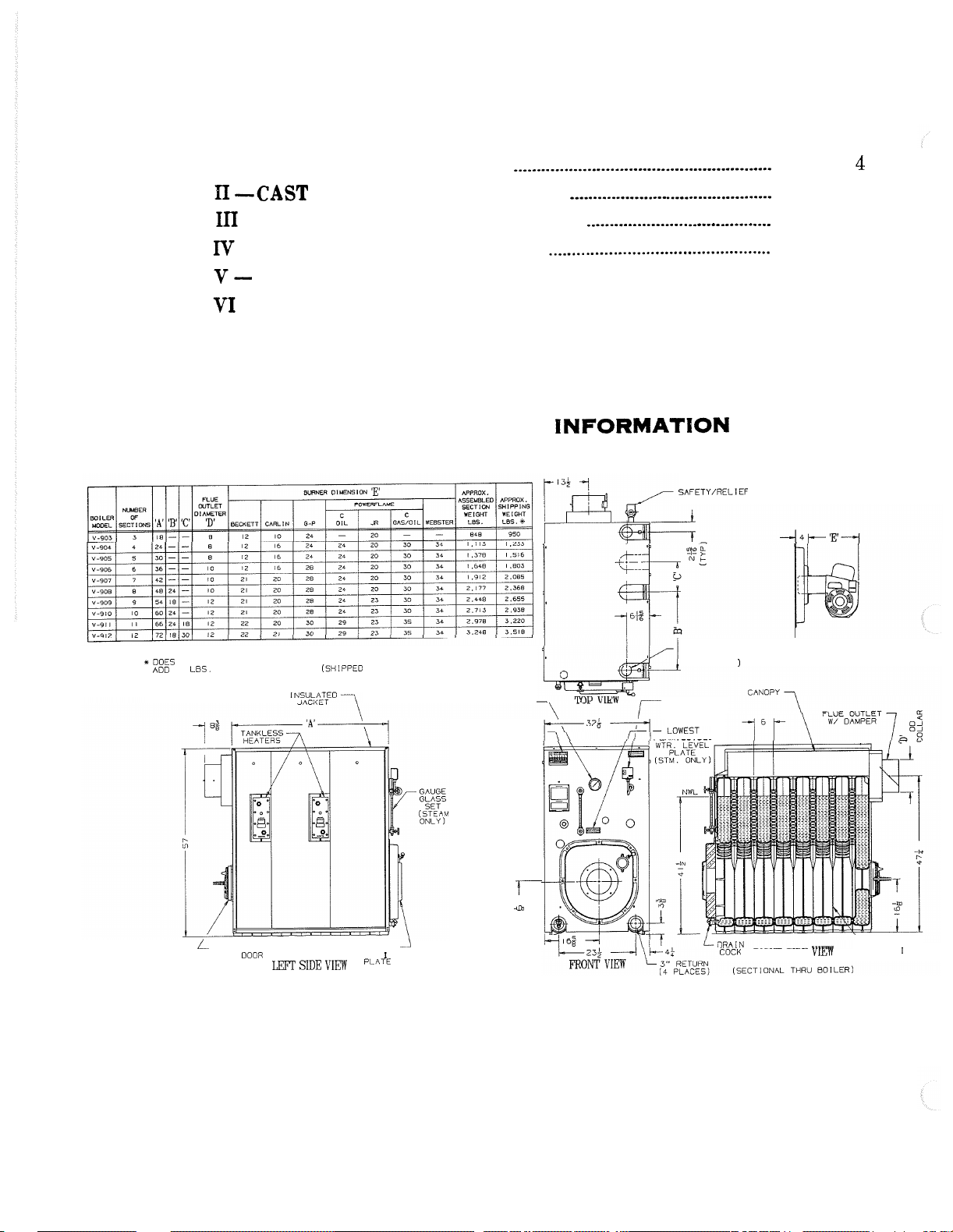
TABLE
OF CONTENTS
SECTION I - GENERAL INFORMATION
SECTION
SECTION
SECTION
SECTION
SECTION
PI
--CAST IRON BLOCK ASSEMBLY
111
-
INSTALLATION INSTRUCTIONS
IV
-
OPERATING INSTRUCTIONS
V
--
SERVICE INSTRUCTIONS
VI
-
REPAIR PARTS
SECTION
.............................................................................
I
GENERAL INFORMATlON
........................................................
............................................
........................................
..............................................
........................................................
SAFETY/RELIEF
VALVE
Page
Page
Page
Page
Page
Page
4
7
12
24
27
29
+DOES NOT INCLUDE BURNER MOUNTING PLATE.
ADO
45
LBS.
FOR
M
O
U
N
T
I
NG PLA
T
E
(SHIPPED
L
PRESSURE
DOOR MOUNT I NG
RELIEF
ASSEMBLY
LEFT
SIDE
vlmy
SEPARATELY
BURNER
PLATE
-3"
TAPPING
(TYPICAL ALL
S
U
P
PLI
E
S
).
GAUGE
RATING
PLATE
-
-
PRESSURETROL
(STEAM ONLY)
PERMISSIBLE
)
BURNER
DETAIL
t
-im
in
a
COCK
RIGHT SIDE VIEW
CAST IRON
SECT l ONS
Fig.
1
Page 5
.
l
)
GHT
I
WATER
BOILER
(LBS.
WE
W/
I
)
S
N
O
LL
FULL
WATER
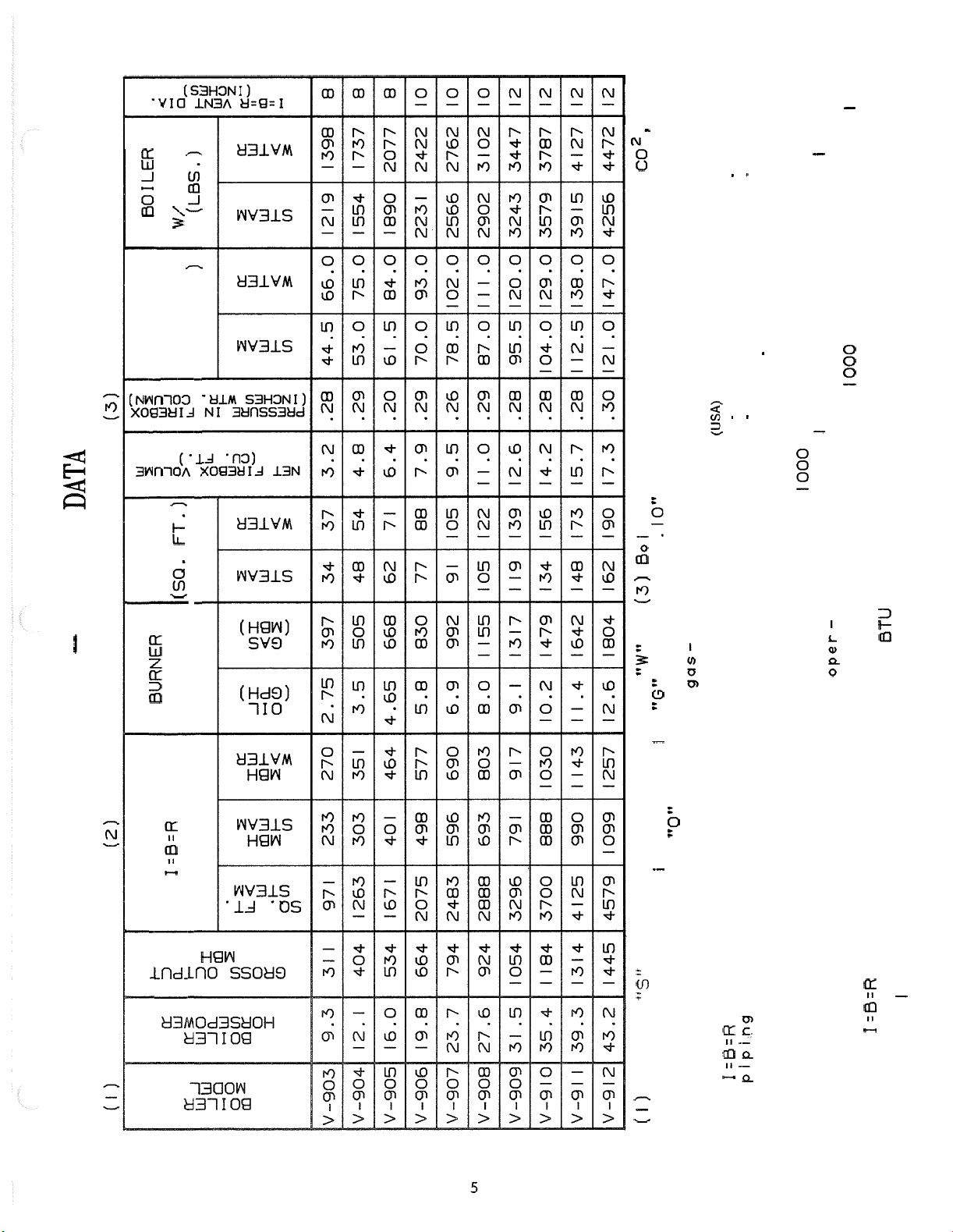
RATINGS
-
I
TABLE
A
G
CONTENT
(
NG
I
FT.)
HEAT
SURFACE
(SQ.
T
U
P
N
I
BURNER
CO',
12.5%
.lo" water column pressure at boiler
+
£301 ler ratings are based on
flue outlet.
MAXIMUM ALLOWABLE WORKING PRESSURE:
(3)
-
"W"
,
"G"
x
l
PSI
45
15 PSI
-
-
WATER
PSI
70
-
PSI
15 PSI STEAM
50
-
-
(USA) (CANADA)
STEAM
WATER
OPTIONAL SPECIAL ORDER
cated,
I
nd
i
feet on
2000
feet above sea leve
1000
tudes above those
i
t
l
feet on oil and
1000
for each
4%
the ratings should be reduced at the rate
gas. For a
up to
-
of
Ratings shown above apply at altitudes
BTU
based
is
140,000
GPH
RATING
I=B=R
NET
indicates oil
Suf f
.
"0"
ler
i
fired,
-
indicates steam boi ler
indicates comblnat ion gas-
"
'5**
Suffix
)
(I
GO
"
indicates gas
indicates water bo
fired,
oil fired.
net ratings shown are based on
I=B=R
(2)
piping and pickup allowances which vary
for water.
from 1.333 to 1.315 for steam and 1.15
burner capacity in
on.
l
I=B=R
ments, such as intermittent system oper-
Consult manufacturer for installations
having unusual piping and pickup require
at ion, extensive piping systems, etc.
per gal
The
on oil having a heat value of
Page 6
@INSPECT SHIPMENT carefully for any signs of damage.
A. ALL EQUIPMENT is carefully manufactured, inspected
and packed. Our responsibility ceases upon delivery of
crated Boiler to the carrier in good condition.
B.
ANY
CLAIMS for damage or shortage in shipment must be
filed immediately against the carrier by the consignee. No
claims for variances from, or shortage in orders, will be
allowed by the manufacturer unless presented within sixty
(60) days after receipt of goods.
A. PROVIDE
so
as
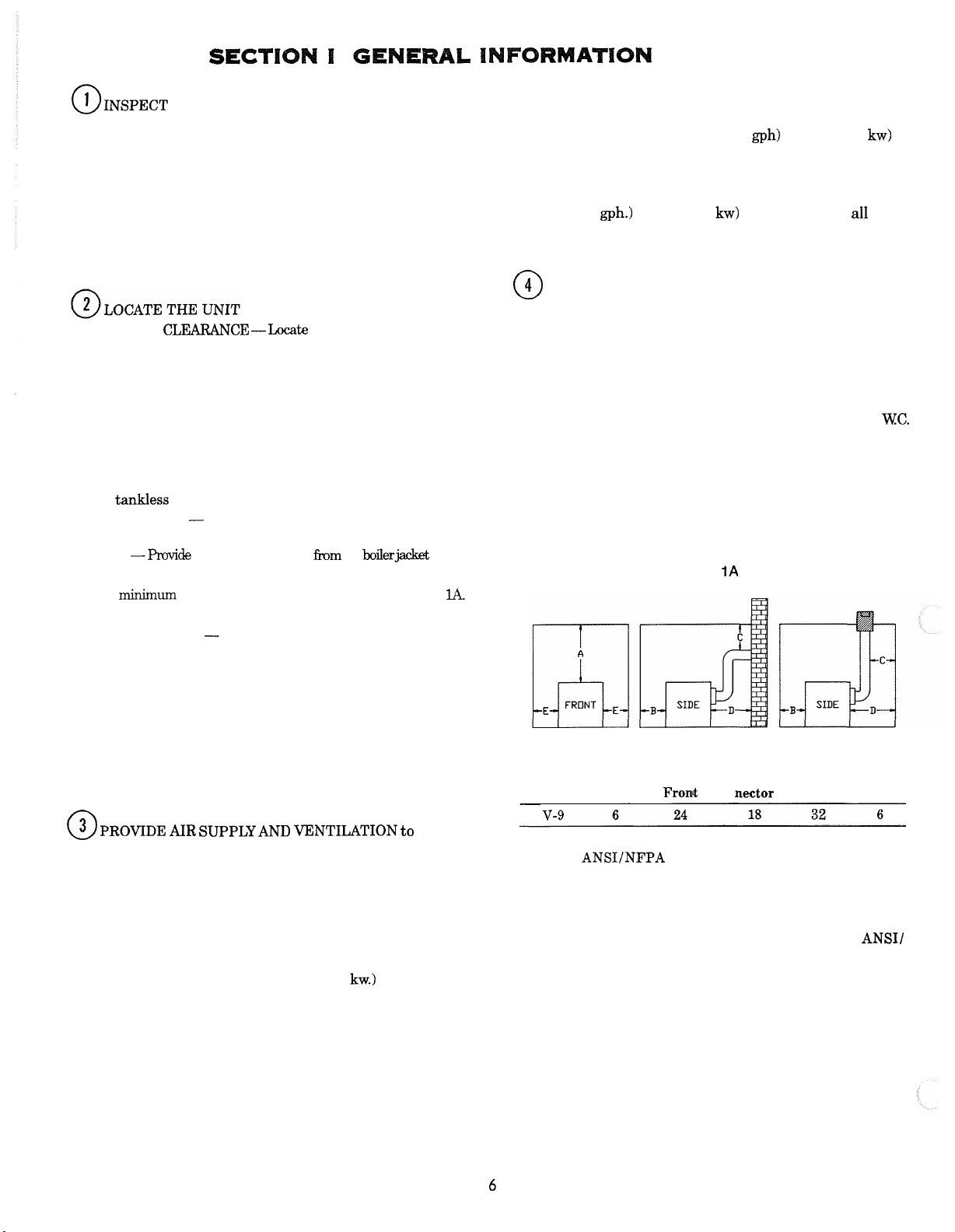
CLEARANCE -Locate the unit in the boiler room
to
provide
ease
of venting and adequate clearance for
maintenance, serviceability, and installation of piping.
-
FRONT
Provide 48" service clearance for removal, main
tenance, and servicing or burner and controls.
REAR
-
jacket of 36
Provide a minimum clearance from the boiler
"
for access to pressure relief door, flame ob
servation, port and flue damper.
LEFT SIDE
boiler jacket of 35
-
Provide a minimum clearance from the
"
for installation and removal of the
tankless heaters and for cleaning of flueways.
RIGHT SIDE
boiler jacket of
TOP
-
Refer to Figure
B.
For
minimum
C.
PROVIDE ADEQUATE FOUNDATION for the unit.
1.
CAUTION
PETING.
-
Provide a minimum clearance from the
9.
F'rovide a minimum
1
for boiler dimensional data.
clearances
to
-
DO NOT INSTALL BOILER ON CAR
Boiler is suitable for installation on com
clearance
from the boilerpcket of 21".
combustible materials,
See
Figure
Ik
bustible floors.
2. Floor construction should have adequate load bear
ing characteristics to bear the weight of the boiler
filled with water (see Table
1).
A boiler foundation
similar to the one shown in Figure 2 is recommended
if the boiler room floor is weak or uneven or if a wa
ter condition exists.
"r
1.
Where communicating by means of vertical ducts, each
opening shall have a free area of not less than
per 4,000 Btuh (35 sq in. per
(
CONTINUED
)
1
sq in.
gph) (5.5 cm2 per kw) of
total input rating of all appliances in the enclosure.
2. If horizontal ducts are used, each opening shall have
free area of not less than 1 sq in per 2,000 Btuh
gph.) (11 cm2 per kw) of total input of all appli
in per
(70
a
sq.
-
ances in the enclosure.
@
CHIMNEY OR VENT
V-9
The
Series boiler is designed for forced draft firing and
may be used with a conventional natural draft stack or a stub
vent, sometimes called a diesel stack (see Figure 3). See Table
1
for the proper vent size. Draft controls are not normally
-
required, although they may be used on installations where a
natural draft stack is used or on multiple boiler installations
with a common stack. The boiler is provided with a breeching
"
-
pressure in the vent connector box during burner operation.
Figure
1A
damper which should be adjusted to maintain a positive 0.1
WC.
-
-
-
-
Boiler Above Fronk nector Rear Sides
A
B
C
Chimney
Con
-
D
E
@
PROVIDE AIR SUPPLY
Am
vENTILATIoN to accom
modate proper combustion.
For commercial and industrial equipment, permanent
facilities for supplying an ample amount of outside air shall
be provided in accordance with the following.
For boiler rooms adjacent to outside walls, and where
combustion air is provided by natural ventilation from the
outside, there shall be a permanent air supply inlet having
a total free area of not less than
hr.
(35 sq. in. per gal. per hr.) (5.5 cm2per kw.) of total input
rating of the burner or burners and in no case less than 35
sq. in. (0.425 m
2
).
1
sq. in. per 4,000 Btu per
For boiler rooms not adjacent to outside walls, the com
bustion air shall be supplied in a manner acceptable to the
authority having jurisdiction.
A. In the absence of local requirements, the confined space
shall be provided with two permanent openings, one in or
near the top of the room and one near the bottom. The
openings shall communicate by means of ducts, with the
outdoors or to such spaces (crawl or attic) that communi
cate with the outdoors.
-
1:
NOTE
Standard
ment.
NOTE
clearances from combustible material as listed above. Listed
clearances can not be reduced for alcove or closet installations.
NOTE
protection must
NFPA 31
Listed clearances comply with American National
ANSIINFPA 31, Installation
2:
V-9
Series boilers can be installed in rooms with
3:
For reduced clearances to combustible material,
be
standard.
provided as described
of
oil burning equip
in
the above ANSI/
-
-
-
Page 7
6
U8.2 STEEL CHANNEL
-
h-2
NOTE: IF THE BOILER ROOM FLOOR IS WEAK OR UNEVEN
EJL0iz6H'?MFL"fR"1T;:NT5":"01t
IS
RECOMMENDED.
~%'G~RSE~
Fig.
2
SECTION
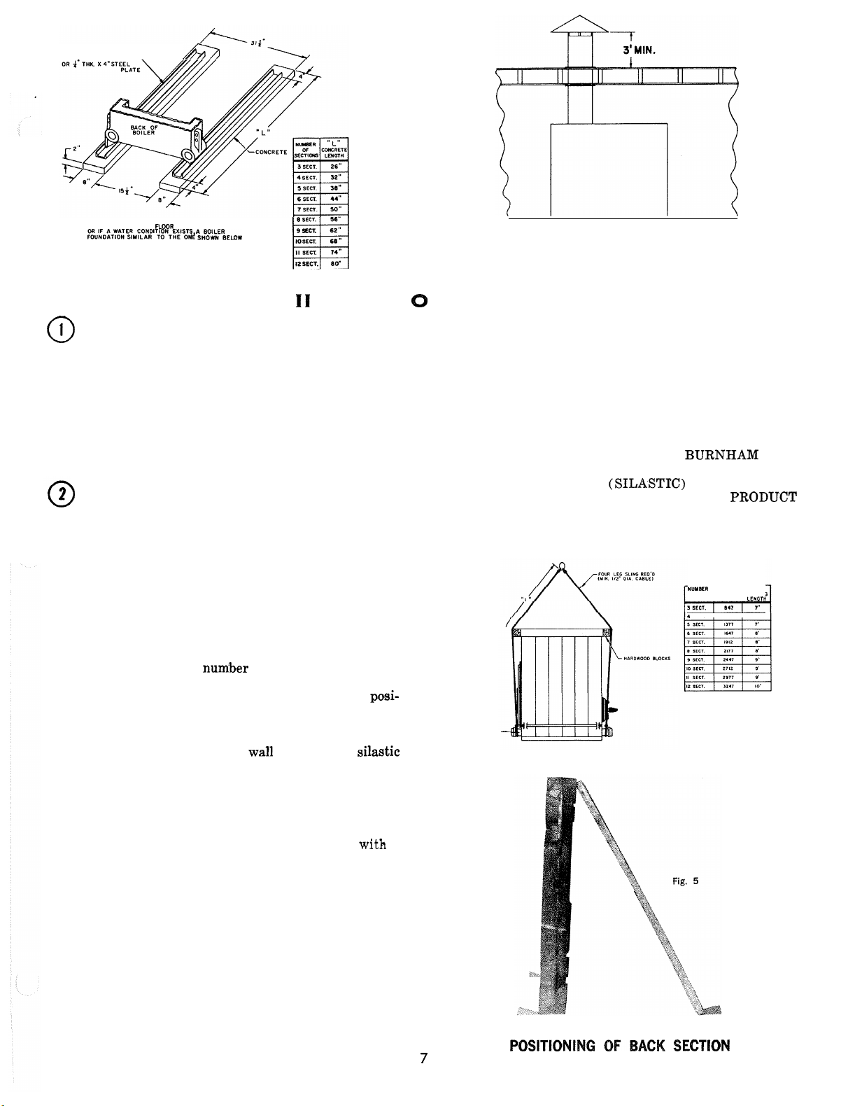
@
FACTORY ASSEMBLED SECTIONS - If the boil
9
SECT.
I1
CAST
er was ordered with factory assembled sections, the assem
blage should be set in the proper location as outlined in
'Section
Figure
1.
Lifting arrangement and weights are given in
4.
The tie-rod nuts should then be loosened until finger
tight. Now proceed to part
"
HYDROSTATIC TEST.
3
of this section on page 12,
"
FIELD ASSEMBLED SECTIONS - If the boiler
was ordered to be field assembled, follow the assembly
procedure outlined on the following pages.
-
A. Assembly of Sections (Manual Draw
Up)
WHEN ASSEMBLING SECTIONS WITHOUT HY
DRAULIC DRAW-UP EQUIPMENT, NEVER AS
SEMBLE MORE THAN ONE 'SECTION AT A
TIME.
IR
-
-
-
-
1
TYPICAL
FOR
N
BLOCK ASSEMBLY
IMPORTANT
-
AS DIRECTED TO INSURE TIGHT JOINTS.
MOST NIPPLE LEAKS ARE CAUSED
ED OR COCKED NIPPLES.
6. IMPORTANT
-
FIRED BOILER AND SEALANT MUST BE AP
PLIED WHERE SPECIFIED FOR PROPER AND
SAFE PERFORMANCE. THE
PORATION HAS APPROVED A SECTION
JOINT SEALANT
ED BY DOW-CORNING UNDER THE PRODUCT
NUMBERS OF 732-RTV, 732-BLll AND 781. ALL
THREE NUMBERS ARE THE SAME MATER
IAL.
ARRANGEMENT
STUB
VENT
Fig.
3
NIPPLES MUST
BE
BY
DRIVEN
TILT
THIS IS A FORCED DRAFT
BURNHAM COR
(SILASTIC) MANUFACTUR
WUYWR
SECTIONS
4
SECT
LENOTH
-
-
-
-
-
A
"
Manual Draw-Up Kit" is available through Burn
ham
by
ordering part num'ber 6082901.
1.
Place the rear section in its approximate final posi-
tion,
as
suitable prop. 'See Figure
outlined in 'Section 1, and support it with a
5.
903 ONLY - Open target wall carton, apply silastic
to back of target wall and secure target wall to rear
section.
2.
Open the Boiler Assembly Carton (s)
3.
Clean nipples and nipple ports thoroughly
.
degreasing solvent and apply nipple lubricant pro
vided.
4.
Drive nipples squarely into section using block of
wood and hammer, or preferably an aluminum
headed hammer, if available.
5.
A special nipple setting gauge is provided for the
nipples.
Gauge nipple in both directions to insure
that it is driven to the proper depth into the nipple
opening. Cut
-
out in gauge must rest on nipple, with
legs of gauge touching finished face of section,
when nipple is properly driven. See Figure 6.
with
-
Fig.
4
LIFTING INSTRUCTIONS
a
-
Page 8
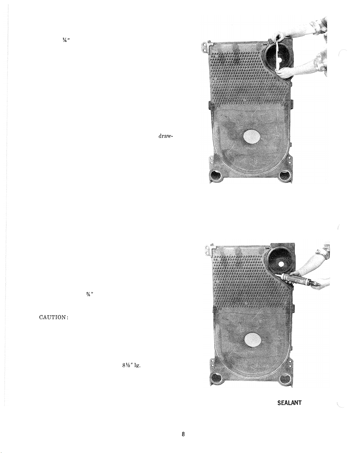
The grooves in the gound joint along the edge
the section should be cleaned with a wire brush.
Then using a cartridge of sealant in a caulking gun,
apply
Y4"
bead of Silastic to one side of each joint
to be mated. Touch up any missed spots before
-
up. Touch-up after draw-up has no value. See
draw
Figure
All sections must be drawn-up iron-to-iron at all
three nipple ports.
7.
of
SECTION'S MUST BE DRAWN
WITHIN FOUR HOURS OF THE TIME WHEN
SILASTIC IS FIRST APPLIED. SILASTIC
CURES IN FOUR HOURS AND WILL NOT
FLOW INTO SEAL GROOVES AFTER FOUR
HOURS FROM APPLICATION, REGARDLESS
OF THE PRESSURE APPLIED.
Tie bolts must be applied immediately after
up. If any joint springs apart it must be re-drawn
tight within four hours of the time of application
of the 'Silastic to that joint.
On long boiler assemblies, it may be necessary to
draw
-
up a partial block if the entire boiler is not
ready to be drawn
first application of Silastic. If the block assembly
time extends overnight, the partial block completed
must be drawn
overnight. If a joint springs out, it must be re
drawn tight within four hours of first application
of Silastic to the joint.
7.
From arrangement of sections chart (see Figure
select next section according to code letters on sec
tion.
IMPORTANT
BLED IN PROPER ORDER.
-
up tight within four hours of the
-
up tight before leaving the boiler
-
SECTIONS MUST BE ASSEM
-
UP TIGHT
draw-
8)
-
-
-
SETTING
OF
Fig.
NIPPLES
6
Clean nipple ports and place section on nipples in
rear section. To facilitate assembly, it is advisable
to enter the upper nipple first in its port, then enter
the lower nipples in their respective ports.
8.
Insert the three
ports in the intermediate section extending them
through the tapped holes in the rear section.
CA.UTION: Care must be exercised to avoid applying
pressure directly on threaded tappings on front and
rear sections with Draw
bly procedures.
Refer to figs.
channel block during assembly procedures.
Place a
upper draw
on each end of the lower draw
nuts and washers. These items are all located in the
Draw
9.
Drive
striking blows as squarely as possible over nipples.
3
"
-
Up Kit. See Figures 9 and 10.
section in place with a heavy block of wood,
%"
draw-up rods through the nipple
-
up channels during assem
9
and 10 for proper placement of
x
12
"
Ig. steel channel on each end of the
-
up rod and an
3
"
x
8%"
1g. steel channel
-
up rods along with
-
APPLICATION
Fig.
OF
7
SEAM
Page 9

V9
SECTION ARRANGEMENT
F - FRONT SECTION w/3"TOP SUPPLY TAPPING
C
-
CENTER SECTION
CT
-
CENTER SECTION w/HEATER OPENING
CX
-
CENTER SECTION w/3"TOP SUPPLY TAPPING
B
-
BACK SECTION w/3" TOP SUPPLY TAPPING
10. DRAW
tightening each draw
that sections are equally spaced, starting with
UP
SECTION SLOWLY AND EVENLY,
-
up rod a little at a time so
low-
draw-up rods.
KEEP NIPPLES A'LIGNED WITH NIPPLE
PORTS. If necessary, tap nipples lightly with
a
!blunt tool or rod to keep nipples from cocking while
-
section are being drawn
SECTION WHEN NIPPLES ARE COCKED. Con
up. DO NOT DRAW UP
tinue tightening draw-up rods equally, periodically
bumping the section with the heavy block of wood
to relieve tension on
meet iron
-to-
11. KEEP DRAW
iron on the ground surfaces.
the draw-up rods, until sections
-
UP ROD THREADS, NUTS AND
WASHERS LUBRICATED with grease or heavy
oil to prevent damage to rods and threads and to
make assembling easier.
12. CONTINUE ASSEMBLING SECTIONS IN
THEIR RESPECTIVE ORDER.
Fig.
8
1.
FOR BOILERS LESS TANKLESS HEATER, REPLACE THE "CT" SECTIONS
NOTES:
WlTH
"C"
2.
3.
SECTIONS.
THE SECTIONS MUST
SHOWN TO INSURE PROPER OPERATION AND ALIGNMENT OF PIPING
WlTH JACKET KNOCKOUTS.
WATER BOILER ONLY. REPLACE "CX" SECTION WlTH
BE
ASSEMBLED ACCORDING TO THE ARRANGEMENT
"C"
SECTION
Be sure to apply the sealant to the groove joints
between adjacent sections as the boiler operates
with a positive pressure in the firebox and products
of combustion will escape between sections unless
the sections are properly sealed. The sealant should
be applied before each section is placed on the
as-
sem'blage.
CHANNEL BLOCK IN POSITION
Fig.
9
Page 10
a. Locate
Boiler Assembly Carton
b.
Locate the Tie-Rod Bundle.
c. Insert tie
V-911
rods must be assembled with tie-rod couplings to
achieve the proper length tie
the coupling is too large to fit through the lugs
on the sections, insert the (2) tie
the lugs before joining with the coupling.
d.
Place a %"-11 hex nut and washer on
of
e. Remove draw-up rods from the section assem
blage.
f. Excess length of tie
they will not extend beyond front and rear
sections. Rods should project equally at each end
to insure proper fit of the jacket.
See Figure
blage. Illustration shows 'boiler equipped with
sections for built
(8)
%"-I1 hex nuts and washers in the
(s)
.
-
rods through lugs on sections. On the
and the V-912, (2) different length tie
-
rod assembly. Since
-
rods through
the tie-rods and
11
turn
until finger tight.
-
rods must be sawed off so
for complete boiler section assem
-
in water heaters.
each
end
-
-
-
13.
After all sections have been drawn up, but before
removing draw
stalled.
-
up rods, the tie-rods must be in
14. If any joint springs apart it must be redrawn with
in four hours of the time of application of the Sil-
astic to that joint.
-
15. Now proceed to part
'%HYDROSTATIC TEST.
3
of this section on page
"
-
12,
SECTION
Fig.
ASSEMBLAGE
11
Page 11
B. Assembly of Sections (Hydraulic Draw-Up)
The entire assemblage may be drawn up at one time
using hydraulic draw
eration is completed within four hours after applica
tion of the sealant.
"
Hydraulic Draw-Up Equipment" is available through
Burnham by ordering part number 6196008.
1.
Repeat steps 1 through 7 under "Assembly of Sec
tions (Manual Draw-Up)
2. Continue assembling sections in their respective or
der until all sections are in the assemblage. Be sure
to apply the sealant to the groove in the ground
joints 'between adjacent sections as the boiler op
erates with a positive pressure in the firebox and
products of combustion will escape between sections
unless the sections
should be applied before each section is placed on
the assemblage.
%"
3. Use
the sections (extra rods and couplings are provided
with hydraulic draw
CA-UTION: Care must be exercised to avoid applying
pressure directly on threaded tappings on front and
rear sections with Draw
bly procedures.
diameter rod (s) and coupling(s) to draw-up
-
up equipment providing the op
."
are properly sealed. The sealant
-
up equipment).
-
up channels during assem
Refer to figs. 9 and 10 for proper placement of
-
-
-
-
-
-
channel block during assembly procedures.
4.
Use two
rod, which is inserted through the upper tappings
and nipple ports. See Figure 12.
5.
Use four
rods, which are inserted through the lower tappings
and nipple ports.
6.
Use hydraulic rams to draw up sections by applying
pressure alternately on the draw
to draw
ground joints.
7.
Repeat steps 13 through 15 under "Assembly of Sec
tions (Manual Draw
12
"
lg. steel channel blocks for the upper
8%"
lg. steel channel blocks for the lower
-
up rods. Continue
-
up until all sections make contact at the
-
Up) ."
-
"HEX
T
-
6
3"
R
X
NUT
E
Q
8l/2"
'D.
LG.
a.
s-
STEE
3"
X
8%''
S
T
E
E
L
CHANNEL^
BLOCK
LL
LVI*J
.L CHANNEL BLOCK
/'
LONG
7
/
-/
ROD
CLAMP
-
PUMP AND
RAM
SET
HYDRAULIC DRAW-UP
Fig.
12
OF
SECTIONS
Page 12

@
HYDROSTATIC TEST -After the boiler sections have
2.
been assembled, it is essential that the boiler be hydrostati-
cally tested before platework, jacket, or piping is installed.
A.
Tankless Heater Installation
If boiler is ordered with
with the gaskets provided. Table
maximum number of heaters permissible per assemblage
and the heater ratings.
tankless heaters, install heaters
I1 on page
13
gives the
D. EXAMINE BOILER CAREFULLY, INSIDE AND OUT
SIDE, to insure against leaks from cocked nipples or
through concealed breakage caused in shipping and han
B. Plug all boiler tappings and fill entirely with cold water. To
protect and safeguard the accuracy of steam or water gauge
supplied, DO NOT INSTALL GAUGE UNTIL AFTER
dling. This precaution is for your protection and will sim
plify handling of necessary replacements and adjustment
claims.
TESTING OF BOILER.
E. After making certain that there are no leaks, drain boiler
C. All completed boilers shall satisfactorily pass the prescribed
and remove plugs for boiler trim and other connections.
hydrostatic test.
1.
STEAM BOILERS: The assembled boiler shall be sub
jected to a hydrostatic test of not less than
@
For boilers with no tankless heaters. proceed to Step
.
-
45
psig.
-
@
4,~oiler Piping. Figure
Hot Water Boiler: The assembled boiler shall be sub-
jected to a hydrostatic test of not less than 1% times the
maximum allowable working pressure.
a. 45 psi mawp
b. 50 psi mawp
c. 70 psi mawp
minimum test pressure is
-
minimum test pressure is 75 psig.
-
minimum test pressure is 105 psig.
68
psig.
-
Install the tankless heater manifolds according to
13.
-
-
-
TWO HEATER MANIFOLD
MINIMUM PIPING RECOMMENDATION FOR
TANKLESS WATER HEATER MANIFOLDS
TYP.
THREE HEATER MANIFOLD
V9
DESCRIPTION
FOUR HEATER MANIFOLD
Fig.
13
FOR JACKET
REMOVAL
NOTES:
1.
IT IS IMPORTANT THAT WATER HEATERS BE CENTRALLY
LOCATED IN BOILER. REFER TO PROPER SECTION
ARRANGEMENT PER FIG.
PRESSURE DROP ACROSS EACH V9-2 TANKLESS
2.
HEATER = 5.25
PSI
(8).
AT
7.5
GPM, FLOW RATE.
Page 13

CONNECT TANKLESS HEATER PIPING AS
SHOWN IN Fig.
Ratings.
THE FOLLOWING GUIDELINES SHOULD BE FOL
LOWED WHEN PIPING THE TANKLESS HEATER:
A. Flow Regulation
If flow through the heater is greater than its rating,
the supply of adequate hot water may not be able to
keep up with the demand. For this reason a FLOW
REGULATOR matching the heater rating should be
installed in the cold water line to the heater. Refer
to Figure
regulator should preferably be located below the inlet
to the heater and a minimum of
inlet so that the regulator is not subjected to excess
temperatures that may occur during
when it is possible for heat to be conducted back
through the supply line. The flow regulator also limits
the flow of supply water regardless of inlet pressure
variations in the range of
B.
Tempering of Hot Water
14.
See Table
14
for piping recommendations. The flow
20
I1
for Tankless Heater
12
"
away from the
"
off" periods
to
125
psi.
required by dishwashers and automatic washers is
possible by piping the hot water from the heater prior
to entering the mixing valve.
be
"
-
C.
D. Hard Water
trapped" by installing it below the cold water
inlet to heater to prevent lime formation in the valve.
Flushing of Heater
All water contains some sediment which settles on the
inside of the coil.
periodically backwashed.
stalling hose bibs as illustrated in Figure
lowing water at city pressure to run into hose bib A,
through the heater, and out hose bib
charge is clear. The tees in which the hose bibs are
located should be the same size as heater connections
to minimize pressure drop.
This is applicable to some city water and particularly
to well water.
cautions are necessary. A water analysis is necessary
and an appropriate water softener installed. This is
not only beneficial to the heater but to piping and fix
tures plus the many other benefits derived from soft
water.
Consequently, the heater should be
This should not be a deterent but pre
The mixing valve should
This is accomplished by in
14
B
until the dis
and al
-
-
-
-
-
Install a mixing valve at the
to avoid risk of burns or scalding due to excessively
hot water at the fixtures.
ing recommendations.
ing valve in accordance with manufacturers instruc
tions.
Installation of a tempering or mixing valve will also
lengthen the delivery of the available hot water by
mixing some cold water with the hot. In addition, sav
ings of hot water will be achieved since the user will
not waste as much hot water while seeking water tem
peratures to his liking. Higher temperature hot water
TANKLESS
BO
I
LER
MODEL
NUMBER OF
I
Adjust and maintain the mix
HEATER RATINGS*
HEATERS INSTALLED
2
tankless heater outlet
Refer to Figure
V9-2
TANKLESS
3
14
for pip
4
3'
FEET
TANKLESS
HEATER
3
I
INLET
1
@
-
-
-
-
-
-
SCHEMATIC
COLD
WATER
SUPPLV
TANKLESS
TEMPERED
HOT WATER
TO FAUCETS
AND SHOWERS
RELIEF LINE AT LEAST
VALVE
HEATER
HIGH TEMP.
WATER FOR
AUTOMATIC
,
FLO~
IN COLD WATER
AHEAD
HEATER
Fig.
14
PIPING
R
E
OF TANKLESS
G
U
L
A
TOR
Ratings are given
continuous
40°F to 140°F with 200°F bol ler water.
in
flow of water heated from
TABLE
gallons per minute
I1
Page 14

@
BOILER PIPING
CONNECT SUPPLY AND RETURN PIPING TO
HEATING SYSTEM.
B.
With STEAM HEATING, see Figure
I=B=R Installation and Piping Guide No.
15,
200.
consult
-
CAUTION
IT IS IMPORTANT THAT THE MINI
MUM PIPING REQUIREMENTS AND ARRANGE
MENT'S BE COMPLIED WITH IN ORDER TO IN
SURE MAXIMUM RELIABILITY PERFORMANCE.
-
A. CLEARANCES
have clearances of at least
All steam and hot water pipes shall
%"
from all combustible
construction.
REAR
OF
BOILER
-
-
-
CAUTION- PARTICULAR ATTENTION SHOULD
BE GIVEN TO THE CONSTRUCTION OF THE
HARTFORD LOOP ON STEAM BOILERS. FIGURE
16
ILLUSTRATES THE RIGHT AND WRONG WAY
TO CONSTRUCT THE STEAM HEADER.
V-903 AND V-904
V
-
911 AND V-912
V
-
905 THRU V-907
I
BOILER
MINIMUM PIPING REQUIREMENTS
STEAM BOILERS
V
-
908 THRU V-910
I
PIPE
SIZE
I
RISER
1
Fig.
15
Page 15

HORIZONTAL
ON RISERS
AL SECONDARY SUPPLV
USE REDUCING ELBOW
OR ATTACH EQUALIZER
TO BOTTOM
OF HEADER
EQUAL12
CORRECT PHYSICAL ARRANGEMENT FOR STEAM HEADERS
4
I
ER
HORIZONTALLY
TO EQUALIZER
IN
*
Optional Secondary Supply connections illustrated in dotted lines are to be used only in addition to supply connections shown in
solid lines not in lieu of.
Fig.
16
T
FOR STEAM HEADERS
Page 16

V-908
AND V-
909
k
"--REAR
O
F
V-910
THRU
\
V-912
MINIMUM PIPING REQUIREMENTS WATER
C.
With forced circulation HOT WATER HEATING, see
Figure
Guide No.
1.
17, consult I=
200.
If this boiler is used in connection with refrigeration systems, the boiler must be installed so that
the chilled medium is piped in parallel with the
heating boiler using appropriate valves to prevent
the chilled medium from entering the boiler, see
Figure
Piping Guides.
18.
Also, consult
B
=
R Installation and Piping
I=B=R
Installation and
Fig.
17
BOILER
MODEL
BOILERS
Y&@'
ARE CLOSED
t%kf
AM
-
OFF SHUT- OFF
SHUT
tN
OPEN
WINTER AND OPEN IN mR
CI
WMTER AND CLOSED IN SUMMER
HEATING
BOILER
WATER
CHILLER
r
VALVE
S%P$&Y
RETURN
7
SpRdzh%
n,y
I
1
2.
If this boiler is connected to heating coils located in
air handling units where they may be exposed to
refrigerated air, the boiler piping must be equipped with flow control valves to prevent gravity
circulation of boiler water during the operation of
the cooling system.
3.
If tankless heater is not used and if the boiler is to
be operated in a system which has a large volume
or excessive radiation where low boiler water temperatures may be encountered
ty circulation system, etc.) the use of a boiler water
bypass is recommended to maintain optimum oper
ation.
(i.e. converted gravi-
1
SUPPLY MAIN
TO COMBINED
HEATING
COOLING
SYSTEM
8
[AIR CUSHION TANK
CIRCULATOR
I
RETURN MAIN
FROM
COMBINED
HEATING
COOLING
4
SYSTEM
8
RECOMMENDED PIPING FOR COMBINATION
HEATING
&
COOLING (REFRIGERATION) SYSTEMS
WATER BOILERS
-
Fig.
18
Page 17

Install a pipe tee between the circulator and boiler
return along with a second tee in the supply piping
as shown in Figure 19. The bypass should be the
same size as the supply and return lines with valves
located in the bypass and supply outlet as illustrated
in Figure 19 in order to regulate water flow for
maintenance of higher boiler water temperature.
Adjust the valves to provide 180°F to 200°F water
temperature when the system water temperature is
at normal operating range.
4.
A hot water boiler installed above radiation level
must be provided with a low water cutoff device
as part of the installation.
@
CANOPY/FLUE OUTLET ASSEMBLY
The parts necessary for items A-C are located in the
canopy carton.
CIRCULATOR
TO
SYSTEM
.
DRAIN
COCK
A. Attach the
end of the canopy with
(2)
canopy mounting brackets to the front
(8)
#I0
x
1/2"
hex washer head
sheet metal screws.
B.
Along the groove provided on top of the sections and
across the top of the front section, place
2
"
wide cera-
felt strips and overlap at corners. See Figure 20.
RECOMMENDED BYPASS PIPING
WATER BOILERS
Fig.
19
GROOVES ON SECTION ASSEMBLAGE FOR CANOPY ATTACHMENT
Fig.
20
Page 18

C.
Loosely attach the canopy to the lugs on the front of
the section assembly with the
nuts, and washers. See Figure
D.
Open the flue outlet carton.
E.
Attach the
the flue outlet assembly that mounts against the back cast
ing and canopy.
F.
Secure the flue outlet to the canopy with the
brass hex nuts and flat washers. Attach the flue out
let to the section assembly with the
and flat washers as shown in Figure
G.
Tighten canopy carriage bolts until canopy is secure.
'18"
x
1" adhesive fiber gasket to the surface of
A"
carriage bolts, lock
21.
(4)
&
"
cap screws
22.
(4)
-
-
A"
-
CANOPY SECURED AND SEALED
TO SECTIONS
Fig.
21
@INSTALL FLUE COVER PLATES over cleanout
openings on left side of boiler as shown in Figure
23.
FLUE OUTLET SECURED AND SEALED
TO CANOPY
CLEANOUT COVER
W/
INSULATION
AND REAR SECTION
Fig.
22
7
C.I. SECTION
/
-
A. Locate the cover plates, carriage bolts, nuts aild wash
ers in the 'boiler assembly carton.
B.
Attach the carriage bolts to the top and bottom of the
flue openings with washers and hex nuts to provide
a
fixed stud.
C.
Install flue cover plates over studs with insulation
against boiler and secure with washers and nuts.
-
CLEANOUT COVER ASSEMBLY
Fig.
23
Page 19

Page 20

@
ASSEMBLY OF JACKET
A.
Open jacket carton and jacket hardware package. Unless otherwise stated, all jacket components are fasten
ed with #8
drive sheet metal screws tight until jacket assembly is
complete.
B.
Attach jacket front panel to front section and jacket
back panel to rear section using the (8)
ping screws. See Figure
ing.
C.
Attach each jacket
channels as shown in the jacket detail on the jacket
assembly drawing.
D.
Attach each 'U/J' channel assembly to the bottom of
the front and back panels using
E.
Attach each remaining 'U' channel to the top of the
front and back panel
metal screws.
F.
Attach the jacket top panel to the front panel, back
panel, and upper
x
.%
"
hex head sheet metal screws.
24
for jacket assembly draw-
'J'
channel to one of the jacket 'U'
(4)
('U'
side down) using
'U'
channels.
#10
sheet metal screws.
(2)
Do not
self tap-
sheet
G.
Fasten the black knobs onto the jacket side panels
#
10
-
using the
H.
Use Figure
left side panels.
I.
Install each panel into position by inserting top of pan
el into upper
towards boiler, and sliding panel down into
J.
Remove the knockouts necessary for tankless heater
operation.
K.
Install the remaining side panels on the right side of
the boiler (order is not important).
L.
Attach the 'D4A' Rating Plate and Water Treatment
Caution Plate (both are in the instructions envelope)
to the front panel using sheet metal screws.
M.
Tighten all sheet metal screws.
machine screws.
25
to determine the correct positions of the
'U'
channel, pushing bottom of panel in
'J'
channel.
-
V-9
JACKET
LEFT
SIDE PANEL ARRANGEMENT
Fig.
25
-C
FRONT
I30
I
60
I
OF
LER
LER
Page 21

@
INSTALL BURNER MOUNTING PLATE
A.
With the use of Silastic, secure the rope gasket to the
groove along the mounting plate opening in the front
section.
B. Mount the burner mounting plate assembly to the front
(8)
section with the
&"-I8 x 1" cap screws and flat
washers located in the burner mounting plate carton.
'See Figure
26.
Refer to Oil Burner Installation Instructions and
Burner Specification Manual, for proper installation, fuel
piping, wiring, burner adjustment and service instruc
tions. Using a hacksaw blade or knife, cut hole to the
proper size in the burner plate insulation for receipt of
burner air tube. Burner is mounted on burner mounting
plate using the
(4)
%"-I6
hex nuts and flat washers lo
cated in the burner mounting plate carton.
BURNER MOUNTING PLATE
Fig.
26
A. Apply a
Y4"
bead of Silastic along the groove on the
inside face of the pressure relief door.
B. Mount the pressure relief door onto the rear section
using the
(4)
$6"-18
x
1"
cap screws and washers locat
ed in the canopy carton.
@
INSPECT SEAL
After the platework is in place, a visual inspection
should be made of all sealed joints and repairs made if
necessary.
A
darkened boiler room with a light source in
the combustion space and canopy 'will aid this inspection.
REAR
FRONT
moN
v-9
SERE3
PURPOSE
PING
LOCAT I ON I NCHES
-
I
1
I
(A)
1
(B)
1
(I)
I
(K)
1
V-9
PURPOSE
SIZE
I
I
STEAM
3
1
3
1
14
I
SAFETY VALVE I RELIEF VALVE
I
AUXILIARY TAPPINGS AUXILIARY TAPPINGS
SERIES BOILER
OF
TAPPINGS
Fig.
27
OF
TAPPINGS
I
S
U
P
P
L
Y
RETURN
Born
LER
m0N
I
WATER BOILER
SUPPLY
RETURN
CROWN INSPECTION/WASH-
OUT (SPECIAL ORDER ONLY
FLOAT L.W.C.O.
L.W.C.0
PROBE
TEMP. LIMIT CTRL.
NOT USED
TEMPERATURE/
PRESSURE GAUGE
SUPPLY
I
I
Page 22

@
STEAM BOILERS - INSTALL STEAM TRIM
Items for steam trim are located in the steam trim
ton (except for the separately ordered low water cutoff
and tankless heater control). Figure
tappings for each item. Figure 29 shows front view of an
assembled steam boiler.
A.
Install the gauge glass set.
27
shows the proner
car-
H.
Plug extra tappings.
I.
Attach the Lowest Permissible Water Level Plate to the
jacket front panel as shown in Figure
x
Yz"
sheet metal screws.
SAFETY
24
with the
VALVE
#8
B. Install the low water cut
C.
Install the Pressuretrol to the boiler using the
(2%") syphon and the
ing.
D.
Install the
hex bushing.
E.
Install the steam gauge using the
hex bushing.
F.
Install the safety valve to the back section as shown
in Figure
provided for blow
G.
For boilers with tankless heaters, install the operating
control in an unused tapping through one of the heater
plates.
%"
drain cock using the
28.
The safety valve is installed in the tee
-
off.
%"
-
off piping.
NPT x
%"
FPT hex bush
3"
NPT
%"
NPT
x
94''
x
%"
%"
x
90
-
FPT
FPT
---
I
11
BLOW-OFF
CONNECTION
IBACK
STEAM BOILER-SAFETY VALVE HOOK-UP
Fig.
28
OF
I I
STEAM BOILER - FRONT VIEW
Fig.
29
Page 23

@
WATER BOILERS - INSTALL WATER TRIM
Items for water trim are located in the water trim car
ton (except for the separately ordered low water cutoff).
Figure
ure
A. Install the temperature pressure gauge.
B.
C.
D. Install the
E.
F.
CAUTION:
sion of the iron and steel boiler components, which
to
oxygen absorption in the
ing the boiler. Problems caused by oxygen contamination of
boiler water are not covered by
such as:
27
shows the proper tappings for each item. Fig
31
shows front view of
Install the low water cutoff.
Install the immersion well and mount the aquastat on
to the well.
%"
hex bushing.
Install the pressure relief valve as shown in Figure
Plug extra tappings.
drain cock using the
an
assembled water boiler.
3"
NPT x
%"
FPT
OXYGEN CORROSION
Oxygen contamination of the boiler water
failure.
There are many
1. Addition of excessive make
2.
3.
As
such, any system must be designed to prevent
tem leaks.
Absorption through open tanks and fittings.
Oxygen permeable materials in the distribution system.
fnst place or prevent it from reach
Burnham's standard warranty.
possible causes of oxygen contamination
-
up water as a result of sys
will
cause corro
can
30.
lead
-
-
/-PRESSURE RELIEF
VALVE
-
PtPED
-
-
PRESSURE SAFETY RELIEF
-
-
WATER BOILER
VA
Fig.
30
In order to insure long product life, oxygen sources should
be eliminated. This
ing measures:
1.
Repairing system leaks to eliminate the need for addi
tion of make-up water.
2.
Eliminating open tanks from the system.
3.
Eliminating andlor repairing fittings which allow oxy
gen absorption.
4.
Use of non-permeable materials in the distribution.
@
INSTALL ELEICTRIC WIRING in accordance with
~itional Electric Code and local regulations. A separate
ELECTRICAL CIRCUIT should be run from meter with
a Fused Disconnect Switch in this Circuit.
CANADA
Electrical features of Fuel Burning Equipment
oil).
-
can
be accomplished by taking the follow
Refer to CSA Standard
C22.2
Part
1,
(gas
1990,
and
-
-
-
WATER BOILER
Fig.
-
31
FRONT
VIEW
Page 24

SECTION
IV
OPERATING INSTRUCTIONS
NOTE: It is important, especially in a steam system,
to properly remove the oil and dirt from the system. Fail
ure to clean the system can result in erratic water lines
and surging.
CLEAN HEATING SYSTEM IF boiler water or con
densate return water is dirty or if erratic water lines or
surging exist after a few days of boiler operation.
to step 6 for proper cleaning instructions for steam and
water boilers.
-
A. STEAM BOILERS
As shown in Figure 1, the normal water line is
from the floor. At the start of each heating season
and once or twice during the season try 'SAFETY
VALVE to be sure it is in working condition.
this, fasten wire or cord to lever of valve and pull
-
lever
B. HOT WATER BOILERS. Fill entire heating system
with water and vent air from system. Use the follow
ing procedure on a Series Loop 'System installed as per
Figure 17
1.
standing safe distance away from valve.
:
Close all but one zone valve.
Fill boiler to normal water line.
Refer
41%"
To do
ED. EXCESS PRESSURE
TION, COULD CAUSE DAMAGE TO HEATING 'SYS
TEM.
DO NOT draw water from boiler while in use. When
adding water while boiler is in operation, do not open
supply valve fully but add water slowly.
-
-
-
@SET CONTROLS with burner service switch turned
A. PRESS RED RESET BUTTON on
relay and release.
B. On STEAM BOILERS set cut-in pressure on PA404
Pressuretrol for three
pressure for two (2) pounds. These pressures may be
varied to suit individual ,requirements of installation.
C. On STEAM BOILERS WITH
TIC WATER HEATER'S, set boiler water tempera
ture dial on low limit operating control at 160°F
(max.). Set differential at 10".
D. ON WATER BOILERS WITHOUT
HEATERS, set high limit dial on 'L4006A at 210°F.
This temperature may be varied to suit requirements
of installation.
E. ON WATER BOILERS WITH TANKLES'S HEAT
ERS, set low limit operating control dial
high limit dial 210°F.
minimum of 20 below .high limit setting.
ential at
25".
I'S DANGEROUS, IN ADDI-
R8184 Protecto
(3)
pounds and differential
TANKLESS DOMES
TANKLESS
at
Operating control must
160°F and
,be a
Set differ
-
-
-
-
-
-
2.
Open drain valve on purge fitting.
3.
Open fill valve.
4. Close purge valve.
5.
Open relief valve on boiler.
6. Allow water to run out of purge fitting drain valve
until zone has been purged of air and filled with
water.
7.
Open zone valve to the second zone to be purged,
then close the first. Repeat
zones have been purged but always have one zone
open. At completion open all zone valves.
8.
Close drain valve on purge fitting.
9.
When water discharges from relief valve, release
the lever on the top of the relief valve, allowing
it to close.
10. Continue filling the system until the pressure
gauge is at desired working pressure.
11.
Open purge valve.
A
ON
MUST NOT EXCEED
BOILER IS EQUIPPED ESPECIA'LLY FOR 70
POUNDS MAXIMUM WORKING PRESSURE. IF
BOILER PRESSURE
OF SAFETY RELIEF VALVE, IT MUST BE,RELIEV-
ED TMMEDIATELY AND THE CAUSE OF RELIEF
VALVE FAILURE INVESTIGATED AND 'CORRECT-
HOT WATER SYSTEM THE PRESSURE
50
POUNDS UNLESS THE
EX.CEED'S 'PRESSURE SETTING
th,is step until all
@
ADJUST BURNER according to the Burner Manual.
A. FLAME FAILURE
The V-9 boiler controls operate the burner automatic
ally. If for unknown reasons the burner ceases to
fire and the reset button on the primary control is
tripped, the burner has experienced ignition failure.
Before pressing the reset button, call your service
man immediately.
CAUTION: Do not attempt to start the burner when
excess oil or gas has accumulated in the combustion
chamber, when the unit is full of vapor, or when the
combustion chamber is very hot.
@
TEST CONTROLS
Before installation of the boiler is considered complete
the
operation of the boiler controls should be checked,
particularly the low water cutoff and the high limit con
trol.
A. CHECK OPERATING CONTROL OPERATION.
Raise and lower operating control setting as required
to start and stop burner.
B.
WARNING - CHECK HIGH LIMIT CONTROL
Jumper Operating Control Terminals. Allow burner
to operate until shutdown
considered complete until this check has been made.
REMOVE JUMPER.
by
limit. Installation is not
-
-
-
-
Page 25

C. OHECK LOW WATER CUTOFF control with water
level at normal water line (see Figure 1). Raise operat
ing control setting to allow burner to operate. Open
boiler drain to allow water level to drop to bottom of
sight glass until burner operation is shut down by low
water cutoff.
Close boiler drain and refill to normal water line.
Burner should automatically restart during fill. Reset
operating control.
PROBE AND FLOAT TYPE LOW WATER CUT
OFF DEVICES REQUIRE ANNUAL INSPECTION
AND MAINTENANCE. Refer to step
Instructions for proper cleaning instructions.
D.
CHECK OPERATING CONTROL on boiler equipped
tankless heaters. With burner off, draw hot
with
water until burner starts, then turn off hot water and
check burner shutdown.
0
BOILER AND SYSTEM CLEANING INsTRuc-
TIONS FOR TROUBLE FREE OPERATION.
A
qualified
be
consulted for recommendations
water treatment chemical specialist should
regarding
4
of Service
appropri
ate chemical compounds and concentrations which are
compatible with local environmental regulations.
A. Steam Boilers
the surface
-
-
-
boiling and trickle of overflow for several hours
until the water coming from the overflow is
clear.
d. Stop 'burner and drain boiler in a manner and to
a location that hot water can be discharged with
safety.
e. Refill boiler to normal water line. If water in
gauge glass does not appear to be clear, repeat
steps (a.
longer time.
2.
Low pressure steam boilers such
be maintained with appropriate water treatment com
pounds. Add suitable water treatment compounds
ommended by your qualified water treatment company.
3.
Remove temporary surface blowoff piping, plug tap
ping and reinstall safety valve. Boil or bring
water temperature to 180°F promptly in order to
drive off the dissolved gases in the fresh water.
4.
If unsteady water line, foaming or priming persist,
install gate valve in Hartford Loop'and drain valves
in return main and at boiler and proceed as follows
a.
Connect hoses from drain cocks to floor drain.
Close gate valve in Hartford Loop and open drain
cock in return main. Fill boiler to normal water
level, turn on oil burner and operate boiler
this water level for at least 30 minutes after the
condensate begins to run hot, then turn off burn
er.
Close all radiator valves. Remove all supply
main air valves and plug the openings in supply
main.
blowoff pipe. Continue this slow
thru c.) and boil out the boiler for a
as
the
V-9
series should
as
rec
-
:
at
-
-
-
1.
Oil, greases & sediments which accumulate in a
new boiler and piping must be removed from the
system in order to prevent an unsteady water line
and carry over of the water into the supply main
above boiler. Operate the boiler with steam in the
entire system for a few days allowing the conden
sate to return to the boiler. If the condensate can
temporarily be wasted, operate boiler only for the
length of time it takes for condensate to run clear.
If the latter cannot be achieved or if the condensate
is returned to the boiler, boil out the boiler using
the SURFACE
28.
a. Drain boiler until water is just visible in gauge glass.
Run temporary
connection to
where hot water may be discharged safely. Do not
install valve in this line.
b. Add an appropriate amount of recommended boil out
compound.
c. Start burner and operate sufficiently to boil the
water without producing steam pressure. Boil
for about
ciently to permit a steady trickle of water from
BLOWOFF connection. See Figure
1
W'
pipe line from the surface blowoff
an
open drain or some other location
5
hours. Open boiler feed pipe suffi
b. Draw about
into a container and dissolve into it the appropriate amount of a recommended
pound. Remove safety valve from boiler and
-
-
pour this solution into boiler, then reinstall
safety valve.
c. Turn on burner and keep operating while feeding
water to boiler slowly. This will raise water
level in boiler slowly into supply main and back
through return main, flowing from drain hose at
about 180°F. Continue until water runs clear
from drain hose for at
d.
Stop feeding water to boiler but continue operat
ing burner until excess water in boiler flows out
through supply main and water lowers
steaming) until it reaches normal leveljn boiler.
5
gallons of hot water from boiler
boilout com-
least 30 minutes.
-
(by
Page 26

Turn off burner. Drain boiler. Open all radiator
valves. Reinstall all supply main air valves. Open
gate valve in Hartford Loop.
e. When boiler has cooled down sufficiently
(crown-sheet of
secti0n.s are not too hot to
touch), close the drain cocks at boiler and in re
turn main and feed water slowly up to normal
level in boiler. Turn on burner and allow 'boiler
to steam for 10 minutes, then turn off burner.
Draw off one quart of water from bottom gauge
glass fitting and discard. Draw off another quart
sample and if this sample is not clear, repeat the
cycle of draining the boiler and return main and
refilling the boiler until sample is clear.
f. If the boiler water becomes dirty again at a later
date due to additional sediment loosened up in
the piping, close gate valve in Hartford Loop,
open drain cock in return main, turn on burner
and allow condensate to flow to drain until it
has run clear for at least 30 minutes while feed-
ing water to boiler so as to maintain normal
water level. Turn off burner, drain boiler, open
gate valve in Hartford Loop, then repeat step
above.
5.
Make pH or Alkalinity Test.
'boiler and system have been cleaned and re-
After
filled as previously described, test the pH of the
water in the system. This can easily be done by
drawing a small sample of boiler water and testing
hydrion paper which is used in the same manner as
litmus paper, except it gives specific readings. A
color chart on the side of the small hydrion dispenser gives the reading in pH. Hydrion paper is
inexpensive and obtainable from
gny chemical sup-
ply house or through your local druggist.
should be higher than 7, but lower than
appropriate water treatment chemicals,
to bring the pH within the specified range.
6.
Boiler is now ready
to
be put into service.
B. Water Boilers
1. Filling of Boiler and System
-
General - In a hot
water heating system, the boiler and entire system
(other than the expansion tank) must be full of
water for satisfactory operation. Water should be
added to the system until the boiler pressure gauge
registers normal system design operating pressure.
To insure that the system is full, water should come
out of all
2.
Boiling Out of Boiler and System. The oil and
grease which accumulate in
can
,air vents when opened.
a
new hot water boiler
,be washed out in the following manner.
a. Remove safety relief valve using extreme care to
avoid damaging it.
an
b. Add
appropriate amount of recommended boil out
compound.
c. Reinstall safety relief valve.
d. Fill the entire system with water.
e. Start firing the 'boiler.
f. Circulate the water through the entire system.
g. Vent the system, including the radiation.
h. Allow boiler water to reach operating tempera-
ture, if possible.
i. Continue to circulate the water for a few hours.
j.
Stop firing the boiler.
The pH
11.
if
necessary,
Add
k. Drain the system in a manner and to a location
that hot water can be discharged with safety.
1. Remove plugs from all available returns and
wash the water side of the boiler as thoroughly
as possible, using a high-pressure water stream.
-
m. Refill the system with fresh water.
3.
Add appropriate boiler water treatment compounds
as
recommended by your qualified water treatment company
4.
Make pH or Alkalinity Test.
After boiler and system have been
cIeaned and re
filled as previously descri'bed, test the pH of the
water in the system. This can easily be done by
drawing a small sample of boiler water and testing
with hydrion paper which is used in the same man
ner as litmus paper, except it gives specific read
-
ings. A color chart on the side of the small hydrion
dispenser gives the reading in pH. Hydrion paper is
inexpensive and ,obtainable from any chemical sup
-
ply house or thru your local druggist. The pH
should be higher than 7 but lower than
1
appropriate water treatment chemicals, if necessary,
to bring the pH within the specified range. With
'this lower level of protection, care must be exer
11.
Add
-
cised to eliminate all of the free oxygen in the
system.
5.
Boiler is now ready to be put into service.
If, during normal operation, it is necessary to add
water to this boiler more frequently than once a month
consult a qualified service technician to check your system
for leaks. A leaky system will increase the volume of
make
-
up water supplied to the boiler which can signifi
cantly shorten the life of the boiler. Entrained in make
-
up water are dissolved minerals and oxygen. When the
fresh, cool make
-
up water is heated in the boiler the
minerals fall out as sediment and the oxygen escapes as
a
gas. Both can result in reduced boiler life. The accumu
lation of sediment can eventually isolate the water from
contacting the cast iron. When this happens the cast iron
in that area gets extremely hot and eventually cracks.
The presence of free oxygen in the boiler creates a corro
-
sive atmosphere which, if the concentration becomes high
enough, can corrode the cast iron through from the in
side. Since neither of these failure types are the result
of a casting defect the warranty does not apply. Clearly
it is in everyone's interest to prevent this type of failure.
The maintenance of system integrity is the best method
to achieve this.
Page 27

SECT1
@IMPORTANT
structions if it becomes necessary to add water to the
boiler more frequently than once a month.
(?)GENERAL
nually. Service as frequently as specified in paragraphs
below. While service or maintenance is being done electri
cal power to the boiler must be "off".
FLUE at least once each year, preferably at the end of
the heating season.
CLEAN THE VENT SYSTEM
be checked annually for
Obstructions.
Accumulations of soot.
Deterioration of vent pipe or vent accessories due
to condensation or other reasons.
Proper support
tal runs.
-
See Item
-
Inspection should be conducted an-
:
-
no sags, particularly in horizon-
'7
under Operating In
-
Vent system should
V
SERVICE INSTRUCTIONS
2.
-
-
Using wire or fibre bristle brush clean crown of
boiler and inside of water legs.
E
.
REASSEMBLE BOrLER
CAUTION: DO NOT START THE BURNER UN
LESS CANOPY, SMOKEPIPE, BURNER MOUNT
ING PLATE AND ALL FLUE PLATE'S ARE SEC
URED IN PLAICE.
Install the canopy taking care to align the cerafelt
strips. If strips are damaged replace as needed.
Reinstall the flue outlet onto the canopy and rear
section. Replace adhesive fiber gasket if damaged.
Reinstall smokepipe on flue outlet and secure to
collar with sheet metal screws.
Reinstall burner mounting plate to front section
making sure Flextex rope gasket is in place and
forms gas tight seal. If gasket is damaged, replace.
Bolt burner to burner mounting plate. Inspect gas
ket to assure adequate seal, replace if damaged.
Connect oil line (s) and/or gas line (s)
Reinstall flue plates making sure gasket on each
is in place and forms gas tight seal. If damaged,
all edges of the
Silastic sealant when reinstalled until insulation
can be replaced.
cleanout plates should be sealed with
.
-
-
-
-
Tightness of joints.
Remove all accumulations of soot with wire brush and
vacuum. Remove all obstructions. Replace all deter
iorated parts and support properly. Seal all joints.
CLEAN THE BOILER
1.
Remove the smokepipe as necessary to gain access
to the boiler flue outlet.
2.
Remove the flue outlet from the canopy and rear
section being careful not to damage the adhesive
fiber gasket on the flue outlet.
3. Remove the jacket top and left side panels.
4.
Remove the canopy being careful not to damage the
cerafelt gasket.
5.
Loosen nuts securing the flue cleanout plates and
remove the plates. The insulation should be remov
ed with the plates taking care not to damage the
insulation.
6.
Using a
(36
top and side using horizontal and diagonal strokes
for best results.
CLEAN TOP OF BOILER SECTIONS.
Brush and vacuum the tops of the boiler sections.
1%"
"
handle) clean the flueways. Brush from the
diameter wire or fibre bristle brush
FLUEWAYS
WMAINTENANCE OF LOW WATER CUTOFF
VICES.
PROBE AND FLOAT TYPE LOW WATER CUTOFF
DEVICES REQUIRE ANNUAL INSPECTION AND
MAINTENANCE.
A. PROBE 'TYPE LOW WATER CUTOFF
Although these devices are
tion, the probe is exposed to possible contamination
in the boiler water and subject to fouling.
It
is important to physically remove the probe from
the boiler tapping annually and inspect that probe for
accumulation of scale or sediment.
Follow these steps to ,inspect, clean and/or replace the
probe
:
-
Turn off electric service to the boiler.
Drain boiler water to a level below the tapping for
the probe.
Disconnect the low water cutoff control from the
probe.
Dismount the low water cutoff control from the
probe.
sol.id state in their opera
DE-
-
CLEAN THE FIREBOX
1.
Disconnect fuel line(s) and remove burner and
burner mounting plate.
Unscrew the probe from the boiler tapping.
Inspect that portion of the probe that is exposed
to the boiler water for a scale or sediment buildup.
Page 28

7.
Light deposits may 'be removed by wiping the probe
with a damp cloth. Wiping the probe with a cloth
soaked in vinegar will remove more tenacious lime
deposits. The most stubborn deposits may be re
moved from the probe by using a diluted amount
(3
parts of water to
(H,
PO4
1.
Exercise caution when handling phosphoric acid and
follow the instruction label on its container.
1
part) of phosphoric acid
@Check burner and control at least once a year. See
Item 5 under Operating Instructions for control checks.
See V
-
9 Burner Manual for burner tests and adjustments.
-
@LUBRICATE BOILER COMPONENTS according
to manufacturer's instructions. Generally, this involves
the oil burner and circulator. This
lubricant to use, frequency of lubrication, and points to
lubricate.
'includes the type of
Wire brushing of the probe is not recommended as
the soft platinum guard ring sandwiched between
the ceramic insulators may be damaged. Care must
'be taken not to damage this ring in any way or the
useful life of the probe may be shortened.
Clean the pipe threads of the probe to remove old,
hardened pipe dope and other foreign matter.
Apply a moderate amount of good quality pipe dope
to the pipe threads on the probe. Leaving the two
end threads bare. Do not use PTFE (Teflon) tape.
Screw the probe into the boiler tapping.
Mount the low water cutoff control on the probe.
Reconnect the control to probe wiring.
Fill the boiler to its normal waterline.
Add boiler water treatment compound as needed.
Restore electric service to the boiler.
Fire burner to bring the water in the boiler to a
boil to drive off free oxygen.
:
-
WARNING
TO SERVICE: Follow the low water cutoff check
out procedure on page 25.
BEFORE RETURNING BOILER
@
GENERAL MAINTENANCE CONSIDERATIONS
Keep radiators and convectors clean.
If a hot water radiator is hot at the bottom but not at
the top, it indicates that air has accumulated inside
and should be vented. To vent radiator, hold small
cup under air vent (located near top of radiator), open
vent until water escapes and then close.
If much water is added to system, it is advisable to
heat system to a high temperature and vent again.
This will make less venting necessary during the
winter.
Where an expansion tank is used, make sure that
neither the tank nor its drain pipe is exposed to freez
ing temperatures. Never place valves in piping leading
to or from expansion tank.
Boiler and system cleaning will help assure trouble
free operation. See Item
tions for procedure.
6
under Operating Instruc
-
-
B. FLOAT TYPE LOW WATER CUTOFF
During the heating season, if an external low water
cutoff is on the boiler, the blow off valve should be
opened once a month (use greater frequency where
conditions warrant), to flush out the sediment chamb
er so the device will be free to function properly.
Low water cutoffs and water feeders should be dis
mantled annually 'by qualified personnel, to the extent
necessary to insure freedom from obstructions and
proper functioning of the working parts. Inspect
connecting lines to boiler for accumulation of mud,
scale, etc., and clean as required. Examine all visible
wiring for brittle or worn insulation and make sure
electrical contacts are clean and that they function
properly. Give special attention to solder joints on bel
lows and float when this type of control is used. 'Check
float for evidence of collapse and check mercury bulb
(where applicable) for mercury separation or dis
coloration. DO NOT ATTEMPT TO REPAIR MECH
ANISMS IN THE FIELD. Complete replacemsent
mechanisms, including necessary gaskets and installa
tion instructions, are available from the manufacturer.
IF
BOILER IS NOT USED DURING WINTER
TIME, IT MUST BE FULLY DRAINED TO PRE
VENT FREEZE DAMAGE.
-
-
-
-
-
-
Spray inside surfaces with light lubricating or crank
case oil using gun with extended stem so as to reach
all corners.
With steam boilers, at end of season add sufficient
water to fill boiler to top of water column and leave it
that way until fall when water
to proper level. If at this time boiler water is dirty,
drain water, flush out boiler, and refill with clean
water to prescribed water level.
Always keep the manual fuel supply valve shut off if
the burner is shut down for an extended period of
time.
To recondition the heating system in the fall season
after a prolonged shut down, follow the instructions
outlined in Section IV
2
through
5.
-
shouId ,be drained again
Operating Instructions, Items
-
-
Page 29

SECTION
All
V9
for delivery from Lancaster.
These offices can advise as to the availability of their products and repair parts from a more local source.
Series Repair Parts can be ordered through the nearest Burnham Regional Sales office or Manufacturer's Representative
VI
REPAIR PARTS
BURNHAM CORPORATION - REGIONAL OFFllCE
A.
Burnham Corporation - Central and Western Region C. Hurnham Corporation - Metropolitan Region
E
0.
Box
Lancaster,
(717) 293
Fax:
B.
Burnham Sales Corporation - Northeast Region
19
-
27 Mystic Avenue
Somerville, MA 02145
(617) 625-9735
Fax
PA
-
5836
293-5832
:
625-9736
17604-3079
3079
100 Davidson Avenue
Somerset, NJ 08873
(908) 560
Fax
D.
Burnham Corporation - Mid Atlantic Region
P.O. Box 3079
Lancaster, PA 17604
(71'7) 293-5861
Fax
:
560-9814
:
293-5855
-
9800
Contact Regional Office Indicated for your State
Alabama
Alaska
Arizona
Arkansas
California
Colorado
Connecticut
Delaware
Florida
Georgia
Hawaii
Idaho
Illinois
Indiana
Iowa
Kansas
Kentucky
Louisiana
Maine
Maryland
Massachusetts
Michigan
Minnesota
Mississippi
Missouri
Montana
Nebraska
Nevada
New Hampshire
New Jersey
Mercer County
All other Counties
:
New Mexico
New York
Albany, Fulton, Montgomery, Rensselear,
Saratoga, Schenectady, Schoharie, Warren,
Washington Counties B
Sullivan County
All other Counties C
North Carolina
North Dakota
Ohio
Athens, Belmont, Gallia, Jefferson, Lawrence,
Meigs, Monroe, Washington Counties
All other Counties
Oklahoma
Oregon
Pennsylvania
Rhode
South Carolina
South Dakota
Tennessee
Texas
Utah
Vermont
Virginia
Washington
Washington, D.C.
West Virginia
Wisconsin
Wyoming
Canada
Island
Arlington, Accomack, Clarke,
Frederick, Fauquier, Loudoun,
Northampton, Prince William Counties
All other Counties
Fairfax,
A
D
A
A
Page 30

Page 31

V-9
BARE BOILER ASSEMBLY
Item No. Description
1
Front Section 11111
Boiler
V903 V904 V905 V906 V907
V909 V910 V911 V912 Part No.
V908
3 Optional
4 'CX' Center Section (with
5 Baok Section
5A
Target
6 7
7 3
8 Tie Rod Sets
8A Tie Rod Bundle, V-903
8B Tie Rod Bundle, V-904
8C Tie Rod Bundle, V-905
8D Tie Rod Bundle, V
8E Tie Rod Bundle, V-907
8P Tie Rod Bundle, V
8G Tie Rod Bundle, V
8H Tie Rod Bundle, V-910
8
I
8J Tie Rod Bundle, V-912
Cleanout Cover Assembly 23456
9
10
Tankless Heater/Cover Plate Gasket
11
Tankless Heater (1 ea.
12 Blank Heater Cover Plate
13
Burner fltg. Plate Assy. (w/ Observation Port)
Burner
Pressure Relief Door Assembly 11111
Canopy Assembly
Cerafelt Strips
Canopy
Flua Outlet Assembly
-
'CT'
Center, I.L.O. 'C'
(Center Section with
Wall:
V903
"
Cast Iron Slip Nipple 23456
"
Cast Iron Slip Nipple 4 6 8 10 12
Tie Rod Bundle, V-911
(1 ea.
'CT' Section)
or
flaunting
NOTE:
Used.
Burner Mtg. Plate,
fltg. Plate, 6-3/8" dia. Opening
Burner
Burner Mtg. Plate,
Burner
Mtg. Plate. 8-3/8" dia. Opening
fltg. Plate, 9" dia. Opening
Burner
Burner
fltg. Plate, 6-1/2" Notched Opening
Burner
fltg. Plate.
Observation Port Assy.
Observation Port Cover
Observation Port Shutter
Observation Port
Observation Port Shutter Handle
Observation Port Shutter Spring
Observation Port Shutter Spring Pin
Observation Port Shutter Handle Knob
Observation Port Outer Gasket
Observation Port
3/8"-16 x 142" lg. Hex Head Cap Screw
1/4"-20 x 518" lg. Hex Head Cap Screw
318"-16 Heavy Hex Nut (Attch. Burner to Plate)
318" Plain Flat Washer (Attch. Burner to Plate)
Mtg. Plate Insulation, Ceramic Fiber
Canopy Assembly, V
Canopy Assembly, V
Canopy Assembly,
Canopy Assembly. V-906
aopy Assembly, V-907
Canopy Assembly, V
Canopy Assembly, V
Canopy Assembly, V
Canopy Assembly, V
Canopy Assembly, V
Hounting Brackat 22222
Flue Ameambly,
Flue
Asm~bly,
Flue
Amubly, 12" Outlet
Tankless Heater)
3" Supply Tapping)
Only
(not
-
906
-
908
-
909
'CT'
(1 ea. 'CT' Section)
Plate Size Depends on Burner
43/41
"
7-1/2" dia. Opening
8-1/2"
Glasa
Inner Gasket
-
9031
-
904
V-905
-
908
-
909
-
910
-
911
-
912
(112" x 2") (L.F.)
8" Outlet
10" Outlet
-
fiax
shown)
Section)
dia. Opening
Notched Opening
#
11122
4 4 4 4 4
4 4 4 4 4
11111
45678
Page 32

ASSEMBLY
JACKET
BOILER
SERIES
9
V
33
Fig.
REPAIR PARTS FOR JACKET ASSEMBLY
Page 33

i
V-9
JACKET PANELS
Boiler SizeIQuanti ty
Item No. Description
Jacket Front Panel Assembly
Jacket Rear Panel Assembly
Jacket Right Side Panel Assembly
54-114" x 21-318"
54-114" x 22-318"
54-114" x 27-318"
54-114" x 33-318"
54-114" x 11-15/16
54-114" x 29-15/16
Jacket Left Side Panel Assy.
Left Side Panel Assembly
Rear Left Panel Assy.
Interm. Left Panel Assy.
Panel Assy.
Panel Assy.
Panel Assy.
Panel Assy.
"
Panel Assy.
"
Panel Assy.
wl
Htr.
wl
Htr.
(17-15116"W)
Interm. Left Panel Assy.
wlo
Htr.
(11-15116"W)
Front Left Panel Assy.
Front Left Panel Assy.
Jacket Top Panel Assy.,
Jacket Top Panel Assy.,
Jacket Top Panel Assy.,
Jacket Top Panel Assy.,
Jacket Top Panel Assy.,
Jacket Top Panel Assy.,
Jacket Top Panel Assy.,
Jacket Top Panel Assy.,
Jacket Top Panel Assy.,
Jacket Top Panel Assy.,
Jacket
Jacket
Jacket
Jacket
Jacket
Jacket
Jacket
Jacket
Jacket
Jacket
Jacket "J" Channel,
Jacket
Jacket "J" Channel,
Jacket
Jacket "J" Channel,
Jacket "J" Channel,
Jacket
Jacket
Jacket "J" Channel,
Jacket "J" Channel.
"U"
"U"
"U"
"U"
"U"
"U"
"U"
"U"
"U"
"U"
"J"
"J"
"J"
"J"
Channel,
Channel,
Channel,
Channel,
Channel,
Channel,
Channel,
Channel,
Channel,
Channel,
Channel,
Channel,
Channel,
Channel,
wl
wlo
V-903
V-904
V-905
V-906
V-907
V-908
V-909
V-910
V-911
V-912
V-903
V-904
V-905
V-906
V-907
V-908
V-909
V-910
V-911
V-912
V-903
V-904
V-905
V-906
V-907
V-908
V-909
V-910
V-911
V-912
Htr.
Htr.
K.O.
(10-11116"W)
K.O.
K.O.
K.O.
(10-11116"W)
K.O.
(16-11116"W)
V903
V904 V905 V906 V907 V908 V909 V910 V911 V912
-
---------
Part No.
Page 34

STEAM TRlM
/
WATER
TRlM
STEAM TRlM
V903-5 V906-9 V910-12
Pressuretrol, Honeywell
Steam Gauge,
Gauge Glass Set,
Safety Valve Piping:
Nipple, 1
Nipple,
Nipple,
Tee,
Tee,
Tee,
Hex Bushing, 1
Hex Bushing,
Hex Bushing,
Hex Bushing,
Hex Bushing,
Drain Cock, 314" ConBraCo 831-606-01 1 1 1
Safety Valve, ConBraCo
Safety Valve, ConBraCo 113-213-08, 1-114" x 1-112"
Safety Valve, ConBraCo 813-214-08, 1-112" x 2"
Syphon, 114
Plug Extra Tappings:
Pipe Plug,
Pipe Plug,
Pipe Plug,
Pipe Plug,
Lowest Permissible Water Level Plate, Form No. 1204 1 1
S.M.S.,
3-1/2" Dia. Ametek 1144350 1 1 1
"
NPT
1-1/4" NPT x 3-1/2" lg., Black
1-112"
1" NPT, Black
1-114" NPT, Black
1-112" NPT, Black
-
1-112" x 1-1/4", Black
314" WT x 114" FPT, Black (Mount Syphon) 1 1 1
"
MPT x 3/4" FPT, Black (Mount Drain Cock) 1 1 1
3
1/2" MPT x 114" FPT, Black (Mount Steam Gauge) 1 1
" x 90'; 2-112" Extended Leg (Mount Pressuretrol)
1" NPT, Square Head, Black
314" NPT, Square Head, Black
1-1/4" NPT, Square Head, Black
1-1/2" NPT, Square Head, Black
#8
x 112" Phil. Trs. Hd.
PA404A1009 1 1 1
ConBraCo 120-104-10 (11") 1 1 1
x
3-1/2" lg., Black
NPT
x
3-1/2" lg., Black
112" x l", Black
813-202-08, 1"
1
(AB)
Pltd. (Attach Plate)
2
Part Number
80160300
8056022
8056102
1
1 1
1
2 2
WATER TRlM
Aquaatat Controller, Honeywell L4006A2015 1 1 1
Immersion
Temperature Pressure Guage,
Relief Valve Piping:
Nipple,
Nipple, 1
Street Elbow,
Street Elbow, 1"
Hex Bushing,
Hex Bushing,
Hex Bushing, 3
Drain Cock,
Relief Valve,
Relief Valve, ConBraCo 110-214-10, 1" P 501 Working Pressure
Relief Valve, Watts 1740, 1
Relief Valve (Optional),
Preseure 1 1 1
Plug Extra Tappings:
Pipe Plug, 1
Pipe Plug,
Pipe Plug, 314
Well,
Honeywell #123871A, 3/4" NPT 1 1 1
ABlctek 1144840 1 1 1
314"
NPT
"
x 3-1/2" lg., Black
NPT
x 3-112" lg., Black
3/4" NPT x 80°, Ualleable
NPT
x 90 , Malleable
1-112"
HPT
x
1-112"
"
HPT
x
314" NPT, ConBraCo 131-606-01 1 1 1
ConBraCo 110-303-10, 3/4" P 501 Working Pressure 1
"
NPT, Square Head, Black
112" NPT, Square Head, Black
"
NPT, Square Head, Black
3/4" PPT, Black
HPT
x
1" PPT, Black
3/4" PPT, Black (nount Drain Cock) 1 1 1
" P x 1-114" P 501 Working Pressure
Watm 1740, 314"
F
x
1
" F 701 Working
-
-
- -
1
-
-
1
Part Numbers
80160400
80160452
8056028
Page 35

Page 36

SERIES 5B, SERIES 88, PF-5 SERIES, V-9 SERIES,
FD SERIES,
WOODLA NDER, DUO
-
RA
D@
,
AND CAST IRON RA DIA TION
LIMITED WARRANTY
Burnham Corporation warrants to the original owner at the original installation site that products manufactured by Burnham, America's
Boiler Company comply, at the time of manufacture, with recognized Hydronics industry regulatory agency standards and requirements
then in effect and will be free from defects in materials and workmanship for a period of one year after the date of installation.
The remedy for breach of this warranty is expressly limited to the repair or replacement of any part found to be defective under
ccnditions of normal use and does not extend to liability for incidental, special or consequential damages or losses such as loss
of the use of the products,
duct. Burnham Corporation shall have no responsibility for the performance of any product sold by it under conditions varying
materially from those under which such product is usually tested under existing industry standards, nor for any damage to the
product from abrasion, erosion, corrosion, deterioration or the like due to abnormal temperatures or the influence of foreign matter
or energy, nor for the design or operation of any system of which any such product may be made a part or for the suitability of
any such product for any particular application.
For products or parts not manufactured by
respects, conform and be limited to the warranty actually extended to
Warranty service can be obtained by contacting the original installer of the product and providing him with a detailed description of any
apparent defect. If this procedure fails to result in satisfactory warranty service, the owner should notify
America's Boiler Company,
products or items alleged defective shall, in all events, be the responsibility and at the cost of the owner.
Notwithstanding any of the above provisions,
not covered by this warranty, and
product found to be defective.
Equipment furnished by the Buyer, either mounted or unmounted, and when contracted for by the Buyer to be installed or handled
is not covered by this warranty.
operation, warranty, performance, or any other liability connected thereto.
The foregoing provisions of this
extent that any such provision would otherwise have an unconscionable result or would otherwise be inconsistent with applicable
law, such provision shall be limited in effect to the minimum extent necessary to avoid such unconscionable result or inconsistency
with applicable law.
-
Except as provided below with respect to products or parts not manufactured by Burnham Corporation,
inconverlience, loss of time or labor expense involved in repairing or replacing alleged defective pro
Burnham Corporation, the warranty obligations of Burnham Corporation shall, in all
P.O.
Box
3079,
Lancaster,
(2)
Burnham Corporation's liability under this warranty shall not exceed the selling price of the
Burnham Corporation does not assume any responsibility in connection with such equipment,
WARRANTY
PA
17604.
Transportation to a factory or other designated facility for repairs of any
(1)
failures resulting from misuse, improper installation or lack of maintenance are
shall be effective to the maximum extent permitted by applicable law, and, to the
Burnham Corporation by its vendors.
Burnham Corporation, Burnham,
-
Any implied warranties, including implied warranties of merchantability and fitness for a particular purpose shall, to the
extent permitted by applicable law, be limited in duration to a period of one year after the date of installation. To the extent
permitted by applicable law, the remedies for breach of any such implied warranty shall be limited to
forth above with respect to a breach of the express limited warranty provided. With respect to the limitations on implied
warranties set forth above,
Some states do not allow limitations on how long an implied warranty lasts or the exclusion or limitation of incidental or
consequential damages, so the above limitations or exclusion may not apply to you. This warranty gives you specific legal
rights, and you may also have other rights which vary from state to state.
Burnham Corporation hereby notifies each person to whom such warranty is made as follows:
AMERICA'S BOILER COMPANY
Burnham
Corporation
bncaster,
PA
the
17604
remedies set
57028
F
7195
 Loading...