

Page 1
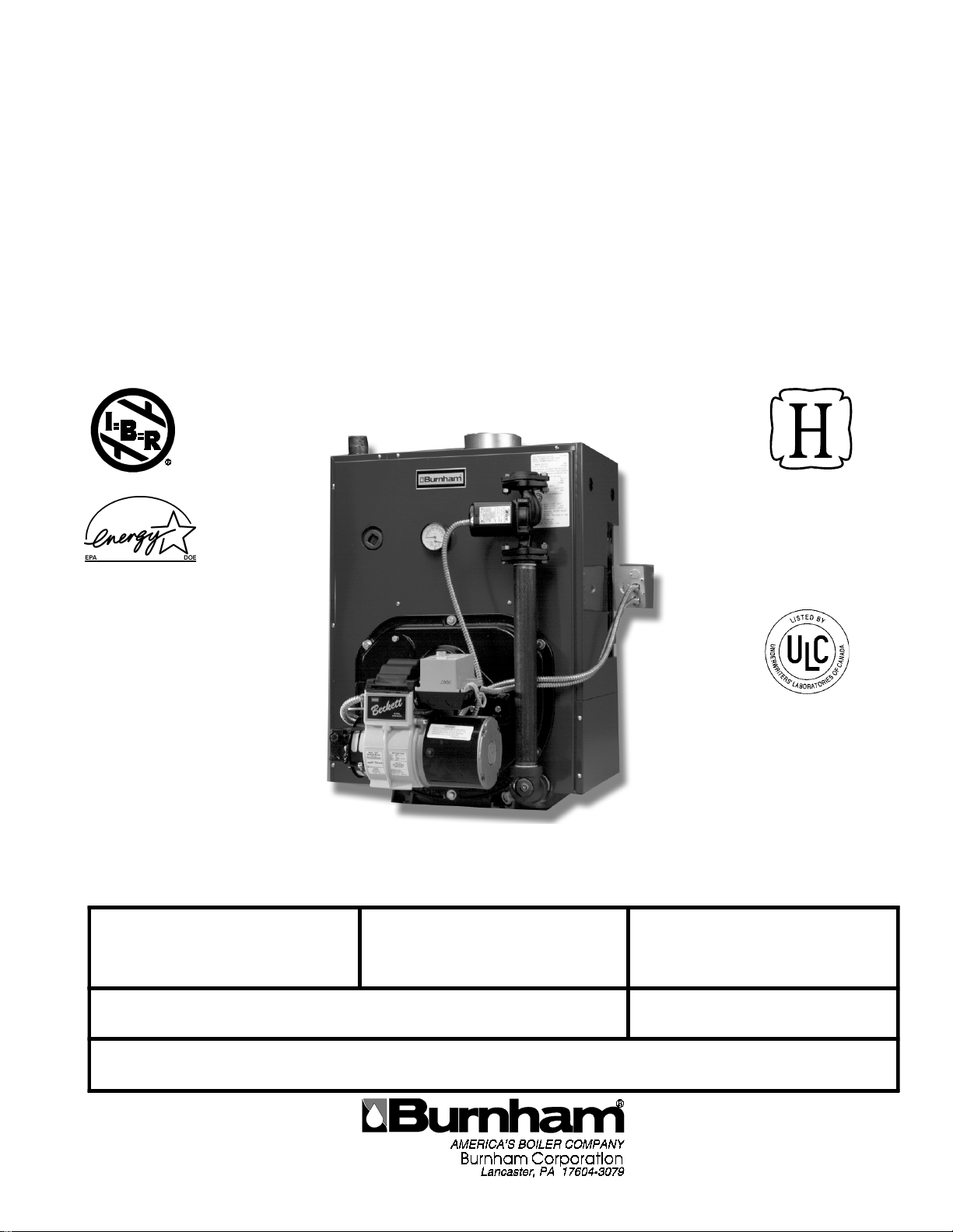
Price - $3.00
INSTALLATION,
OPERA TING AND SERVICE
INSTRUCTIONS FOR
V7 SERIES OIL FIRED BOILER
KNOCKDOWN & P ACKAGED
HEA TING UNITS
These instructions have been
reviewed by ULC and found
suitable for use in the
installation of ULC labeled
As an
ENERGY
STAR® Partner,
Burnham Corporation
has determined that the
V73WR (0.60 GPH),
V74WR (0.80 GPH),
V75WR (0.90 GPH),
and V76WR (1.15 GPH)
meet the ENERGY STAR
guidelines for Energy
efficiency established by the
United States Environmental
Protection Agency (EPA).
For service or repairs to boiler, call your heating contractor. When seeking information on boiler, provide
Boiler Model Number and Serial Number as shown on Rating Label.
Boiler Model Number Boiler Serial Number Installation Date
_V7 ____-____
®
6_ _ _ _ _ _ _
V-7 Series Boilers.
The ULC label or listed
marking on a product is the
only evidence provided by
Underwriters' Laboratories of
Canada to identify products
which have been produced
under the listing and follow-up
service.
Heating Contractor Phone Number
Address
8142711R24-7/99
1
Page 2

IMPORTANT INFORMATION - PLEASE READ THIS PAGE CAREFULLY
1. THIS BOILER HAS LIMITED WARRANTIES, COPIES OF WHICH ARE PRINTED ON THE BACK COVER OF THIS
MANUAL.
2. THIS BOILER IS SUITABLE FOR INSTALLATION ON COMBUSTIBLE FLOORING. BOILER CANNOT BE INSTALLED ON CARPETING.
3. ALL BOILERS MUST BE INSTALLED IN ACCORDANCE WITH NATIONAL, STATE AND LOCAL PLUMBING,
HEATING AND ELECTRICAL CODES AND THE REGULATIONS OF THE SERVING UTILITIES WHICH MAY
DIFFER FROM THIS MANUAL. AUTHORITIES HAVING JURISDICTION SHOULD BE CONSULTED BEFORE
INSTALLATIONS ARE MADE.
IN ALL CASES, REFERENCE SHOULD BE MADE TO THE FOLLOWING STANDARDS:
USA BOILERS
A. Current Edition of American National Standard ANSI/NFPA 31, “Installation of Oil Burning Equipment”, for clearances between boiler, vent connector and
combustible material.
B. Current Edition of American National Standard ANSI/NFPA 211, “Chimneys, Fireplaces, Vents, and Solid Fuel Burning Appliances”, For Chimney require-
ments, type of venting material and clearances between vent connector pipe and combustible materials.
C. Current Edition of American Society of Mechanical Engineers ASME CSD-1, “Controls and Safety Devices for Automatically Fired Boilers”, for assembly and
operations of controls and safety devices.
A. Current Edition of Canadian Standards Association CSA B139, “Installation Code for Oil Burning Equipment”, for recommended Installation Practices.
4. ALL HEATING SYSTEMS SHOULD BE DESIGNED BY COMPETENT CONTRACTORS AND ONLY PERSONS
KNOWLEDGEABLE IN THE LAYOUT AND INSTALLATION OF HYDRONIC HEATING SYSTEMS SHOULD
ATTEMPT INSTALLATION OF ANY BOILER.
5. THE BOILER MUST BE CONNECTED TO AN APPROVED CHIMNEY IN GOOD CONDITION. SERIOUS PROPERTY
DAMAGE COULD RESULT IF THE BOILER IS CONNECTED TO A DIRTY OR INADEQUATE CHIMNEY. THE
INTERIOR OF THE CHIMNEY FLUE MUST BE INSPECTED AND CLEANED BEFORE THE START OF THE HEATING SEASON AND SHOULD BE INSPECTED PERIODICALLY THROUGHOUT THE HEATING SEASON FOR ANY
OBSTRUCTIONS. A CLEAN AND UNOBSTRUCTED CHIMNEY FLUE IS NECESSARY TO ALLOW NOXIOUS
FUMES THAT COULD CAUSE INJURY OR LOSS OF LIFE TO VENT SAFELY AND WILL CONTRIBUTE TOWARD
MAINTAINING THE BOILER’S EFFICIENCY.
6. READ THE LITERATURE ENCLOSED BY THE MANUFACTURER WITH THE VARIOUS ACCESSORY DEVICES.
THESE ACCESSORY DEVICES MUST BE INSTALLED AND USED ACCORDING TO THE RECOMMENDATIONS
OF THE MANUFACTURER.
7. IT IS THE RESPONSIBILITY OF THE INSTALLING CONTRACTOR TO SEE THAT ALL CONTROLS ARE CORRECTLY INSTALLED AND ARE OPERATING PROPERLY WHEN THE INSTALLATION IS COMPLETED.
8. FOR OPTIMUM PERFORMANCE AND SERVICEABILITY FROM THIS BOILER ADHERE TO THE FOLLOWING
RECOMMENDATIONS:
A. DO NOT TAMPER WITH THE BOILER OR CONTROLS. Retain your contractor or a competent serviceman to assure that the boiler is properly adjusted and
maintained.
B. Clean flueways at least once a year - preferably at the end of the heating season to remove soot and scale. Inside of firebox should also be cleaned at the same
time.
C. Have oil burner and controls checked at least once a year or as may be necessitated.
CANADA BOILERS
WARNING
This boiler is designed to burn No. 2 fuel oil only. Do not use gasoline, crankcase drainings, or any oil
containing gasoline. Never burn garbage or paper in this boiler. Do not convert to any solid fuel (i.e.
wood, coal) or gaseous fuel (i.e. natural gas, LP/propane). All flammable debris, rags, paper, wood scraps,
etc., should be kept clear of the boiler at all times. Keep the boiler area clean and free of fire hazards.
WARNING
All boilers equipped with burner swing door have a potential hazard which can cause severe property
damage, personal injury or loss of life if ignored. Before opening swing door, turn off service switch to
boiler to prevent accidental firing of burner outside the combustion chamber. Be sure to tighten swing door
fastener completely when service is completed.
WARNING
High water temperatures increase the risk of burns or scalding injury. Install an automatic tempering
(mixing) valve at the tankless heater outlet to avoid excessively hot water at the fixtures.
2
Page 3
IMPOR TANT
p
g
Before star ting to in st a ll t his o i l b o ile r, r e ad t he se inst r uc t io n s ca r efu lly. K e ep ins t r uc t ions i n legible condition and
osted near oil boiler for reference by o w ne r an d s er v i c e tec hn i cian.
TABLE OF CONTENTS
I. General Information ............................. 3
II. Knockdown Boiler Assembly ............... 7
III. Installation Instructions...................... 12
IV. Operating Instructions ........................ 21
V. Boiler Cleaning .................................. 29
VI. Repair Parts ........................................ 31
Burner Specifications ......................... 46
SECTION I: GENERAL INFORMATION
Figure 1A: V72 thru V79 Water Boiler Without Tankless Heater (WB)
TABLE 1: DIMENSIONAL DATA (SEE FIGURES 1A THRU 1E)
Boiler
Model
No.
V72 11-3/8" 6-3/ 8" 5" 8" x 8 " x 15' --- - 10.6 --- - 381
V71 3 16" 8-3/ 4" 6" 8" x 8" x 15' --- - 1 3.5 ---- 524
V73 15-3/8" 8-3/8" 6" 8" x 8" x 15' 10. 8 13.2 13. 8 47 8
V71 4 20" 10-3/ 4" 6" 8" x 8 " x 15' --- - 15.9 --- - 580
V74 19-3/8" 10-3/ 8" 6" 8" x 8 " x 15' 1 3. 5 15.9 1 9.7 575
V75 23-3/8" 12-3/ 8" 7" 8" x 8 " x 15' 1 6. 1 18.5 2 5.6 674
V76 27-3/8" 14-3/ 8" 7" 8" x 8 " x 15' 1 8. 6 21 31. 4 77 3
V77 31 -3/8" 16 -3/8" 8" 8 " x 12" x 15' 21.2 2 3. 6 37. 3 872
V78 35 -3/8" 18 -3/8" 8" 8 " x 12" x 15' 23.8 2 6. 2 43. 1 971
V79 39 -3/8" 20 -3/8" 8" 8 " x 12" x 15' 26.4 2 8. 8 49. 0 1070
Dimensions
Minimum
Chimney S ize
"A" "B" "C"
NO TE: 1. M aximum Working Pressure 15 PS I (S team) and 30 PSI (Water )
2. The V72 , V713 an d V71 4 Boilers are avail abl e as pack aged wa ter boi lers only
3. The V713 and V714 are no t ULC li sted Models
Water Content -
Ga llons
Steam
Boiler
Water
Boiler
3
Heat Transfer
Surface Area -
Sq. Ft .
Steam Boiler
Approximate
Shippin
(LB.)
Weight
Page 4
Figure 1B: V73 thru V79 Water Boiler with Tankless Heater (WBT)
Figure 1C: V73 thru V79 Steam Boiler with or without Tankless Heater ("SBT" or "SB")
4
Page 5
Βυρνηαµ
Figure 1D: V713 and V714 Packaged Water Boiler Less Tankless Heater (WB)
Burnham
Figure 1E: V713 and V714 Packaged Water Boiler with Tankless Heater (WBT)
5
Page 6
A. INSPECT SHIPMENT carefully for any signs of
damage.
1. ALL EQUIPMENT is carefully manufactured,
inspected and packed. Our responsibility ceases
upon delivery of crated boiler to the carrier in good
condition.
2. ANY CLAIMS for damage or shortage in shipment
must be filed immediately against the carrier by the
consignee. No claims for variances from, or
shortage in orders, will be allowed by the
manufacturer unless presented within sixty (60)
days after receipt of goods.
B. LOCATE BOILER in front of final position before
removing crate. See Figures 1A thru 1E.
1. LOCATE so that smoke pipe connection to
chimney will be short and direct. BOILER IS
SUITABLE FOR INSTALLATION ON
COMBUSTIBLE FLOOR. Boiler cannot be
installed on carpeting.
2. FOR BASEMENT INSTALLATION, provide a
solid base, such as concrete, if floor is not level, or
if water may be encountered on floor around boiler.
3. PROVIDE SERVICE CLEARANCE of at least 24”
on right side of boiler for removal of rear tankless
heater. Provide at least 24” clearance from front
jacket panel for servicing and removal of front
tankless heater (increase to 30" for #A54 heater).
Provide at least 24" clearance from right side of
boiler or top of boiler for cleaning flueways. Boiler
flueways may be cleaned either from the top or
from the side.
4. For minimum clearances to combustible materials.
See Table 2.
C. PROVIDE AIR SUPPLY AND VENTILATION to
accommodate proper combustion. If natural ventilation
is inadequate, provide a screened opening or duct from
the boiler room to the outside. The opening or duct
must be sized so the boiler input will not exceed 4,000
BTUH/Sq. In. of free area. If other air consuming
appliances are near the boiler, the air inlet should be
larger. Consult respective manufacturers.
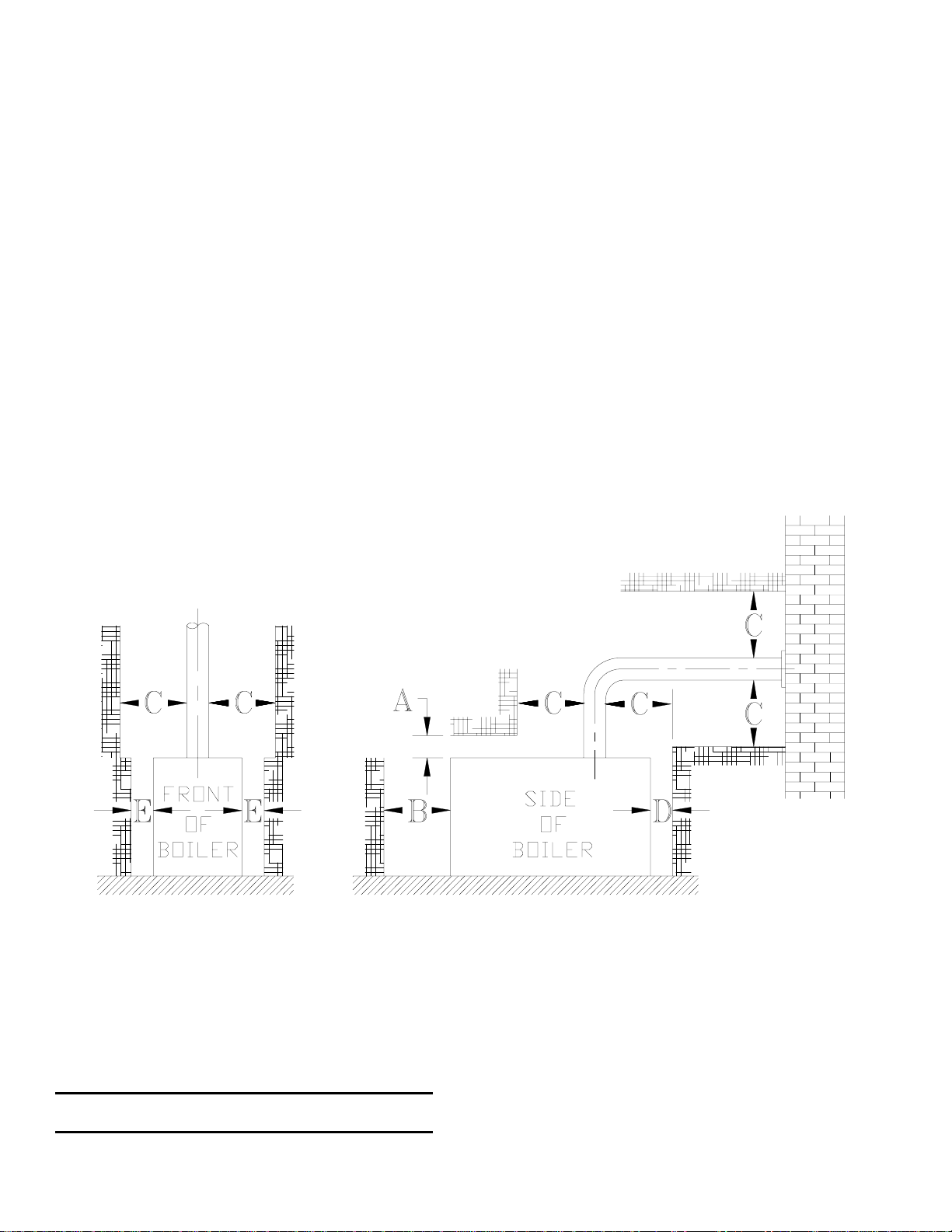
TABLE 2: Minimum Installation Clearances To
Combustible Materials (Inches)
C
Chimney
BoilerAAboveBFront
V7 6 24 18 6 6
ConnectorDRearESides
NO TE 1: Listed c l ear anc es c om ply with A m er ica n
National Standard ANSI/NFPA 31, Installation of Oil
Burning Equipment.
NOT E 2: V7 Serie s boilers can be ins ta lled in room s
with clea rance s from combus tible ma te rial as listed
a bove. List ed c lea ranc es can not b e red uced for
alcove or clos et installations.
N OTE 3: F or redu ced cle ara nc es to co mbus tib le
mater ial, prot ection mu st be pro vided as desc ribed in
the abo ve ANSI/NF PA 31 standa rd.
6
Page 7
SECTION II: KNOCKDOWN BOILER ASSEMBLY
Note: If Boiler is Packaged Go To Section III
A. REMOVAL OF BARE BOILER FROM SKID
1. Boiler is secured to base with 4 bolts, 2 on front and
2 on rear, see Figure 2. Remove all bolts.
2. Tilt boiler to right and to rear. Using right rear leg
as pivot, rotate boiler 90° in a clockwise direction,
and lower left side of boiler to floor. Tilt boiler and
remove crate skid.
Figure 2
B. MOVE BOILER TO PERMANENT POSITION by
sliding or walking.
C. TEST BOILER FOR LEAKS before installing
controls, trim, and jacket, and before connecting to
heating system.
1. Loosen nuts on tie rods until only finger tight.
2. Install pressure gauge (at least 30 P.S.I. capacity), a
hose to the city water and a valve in the supply
tapping. Plug remainder of tappings.
3. Fill boiler with water and apply a pressure of at
least 10 pounds but no more than 30 pounds gauge
pressure.
4. Examine Boiler carefully inside and outside for
leaks or damage due to shipment or handling.
D. DRAIN WATER FROM BOILER. Remove gauge,
valve and plugs from those tappings to be used. Leave
other tappings plugged or bushed according to Figure
4.
E. INSPECT JOINTS BETWEEN SECTIONS. All joints
are factory sealed. If there are any spaces due to
shipment or handling, seal them with boiler putty.
F. INSPECT FLUE COVER PLATES for tightness. If
loose, retighten mounting hardware. If flue plate or
sealing insulation is damaged repair or replace as
needed.
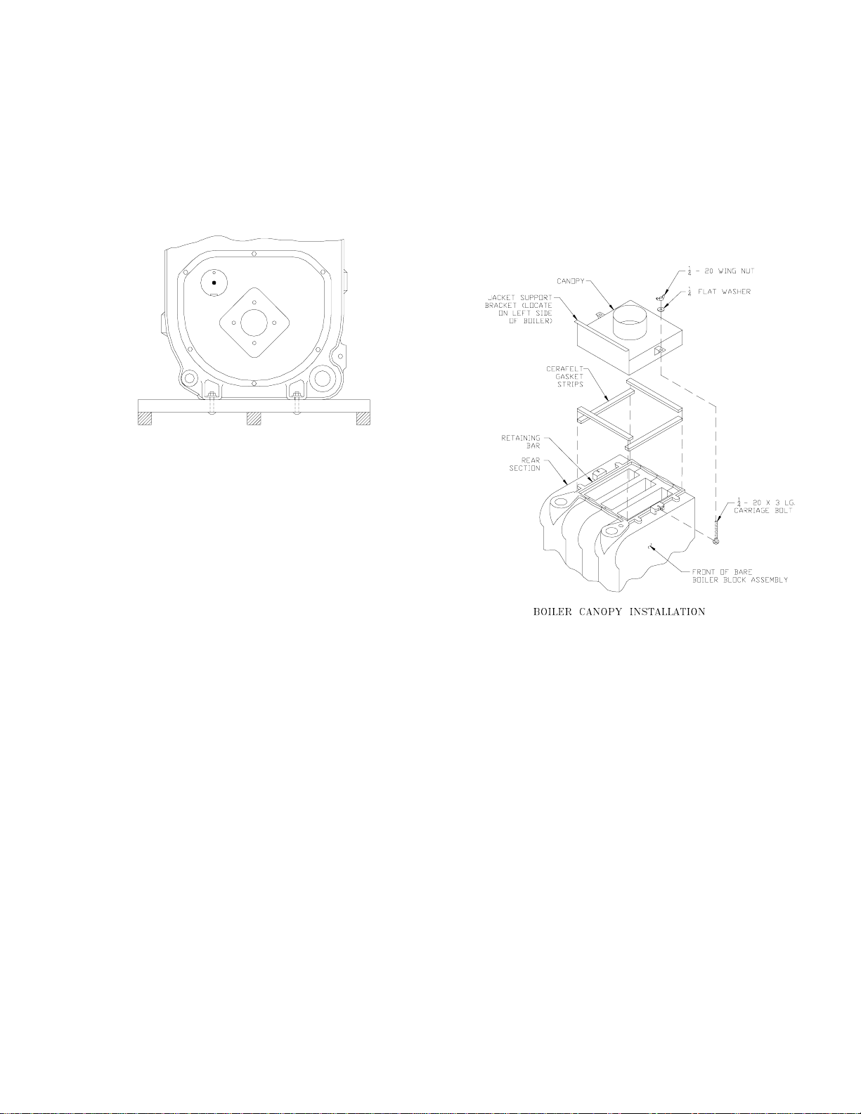
G. INSTALL AND SECURE CANOPY with cerafelt
gasket and hardware provided to ensure gas tight seal
— see Figure 3.
1. Cut two (2) strips 13 ¾” lg. from the roll of cerafelt
gasket insulation. Place one (1) strip across the top
of the front section and the other across the rear
section as shown in Fig. 3. Place gaskets so as not
to allow any flueway blockage.
2. Cut the remainder of the roll into two (2) equal
pieces. Place each piece along the sides, allowing
the ends to overlap the front and rear pieces.
Do not allow any flueway blockage.
3. Position canopy body within the retaining bar
which borders the flueway openings on top of the
bare boiler block assembly.
Figure 3
IMPORTANT: Jacket support bracket must be
facing left side of boiler — see Figure 3.
4. Secure canopy to boiler with two (2) 1/4" - 20 x 3"
lg. carriage bolts, 1/4" flat washers and 1/4" - 20
wing nuts provided.
H. INSTALL the following steam or water trim that
would be concealed or inaccessible after flush jacket is
installed, see Figure 4 for boiler tapping locations and
usage.
1. STEAM BOILER — Top tappings:
a. Tapping "L" — Install 2" plug in rear section
top supply tapping on boiler sizes V73 thru
V75.
b. Tapping “M” — Install ¾” coupling and ¾” x
8” long nipple into ¾” tapping located next to
front section top supply tapping — all boiler
sizes.
2. WATER BOILER — Top tappings:
a. Tapping “L” — Install 2” plug in rear section
top supply tapping on boiler sizes V73 thru
V79.
7
Page 8
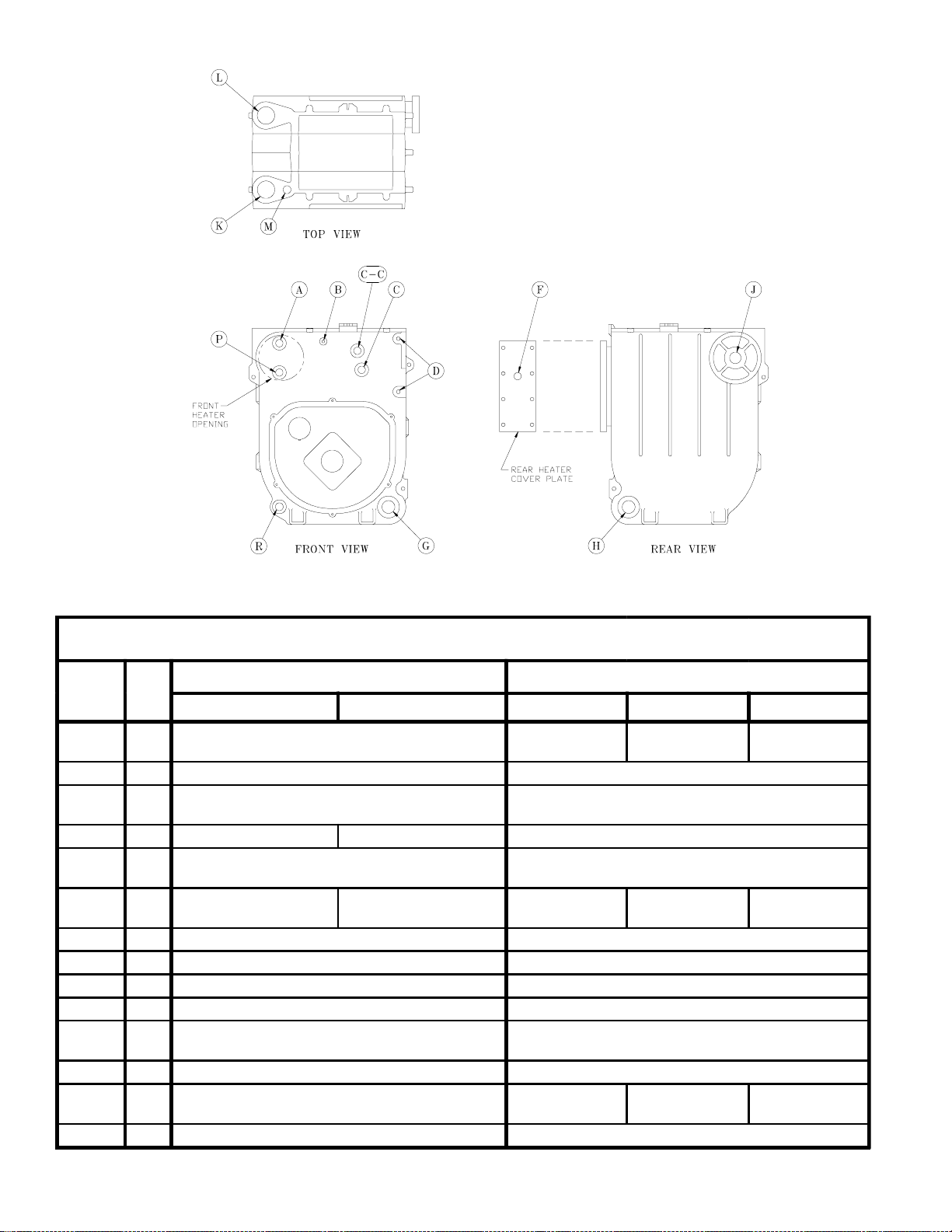
Figure 4: Boiler Tapping Locations and Usage (Knockdown Boilers Only)
g
PURPOSE OF TA PPINGS
Tappin
Location
Size
Steam Boiler Water Boiler
Non-Heater w/Heater Non-Heater Front Heater R ear Heater
A¾"
B ¼" P ressure /Vacuum G au g e Temp era ture/Press ure Gaug e
C¾"
C-C ¾ " Flus h Plug Flus h Plug Flus h Plug
D½"
F ¾" -----
G 1½" B us he d to ¾" for Drainc ock (O ptiona l Re turn ) R eturn
H 1½" R eturn Bus he d to ¾" for Drainc ock (O ptiona l Re turn )
J 1½ " Su rface Blow off - Plugged Flush Plu g
K 2" Front Su pply (3 thru 9 Section) Front Su pply (3 thru 9 Section)
L2"
M ¾" Safety Valve Re lief Valve
P ¾" Au xilia ry Tapping - Plugge d
R ¾" Au xiliary Tapping - Plu gge d Auxiliary Tapping - Plu gge d
Water Gaug e Glass, P ress uretrol, and LWC O (Flo at)
Plug ged, Optional Se co nd Supply (3 thru 5 Section)
PA4 04A Pr es suretrol (Probe LW CO)
Plugg ed (Float LW CO)
Pro be LWC O Std.
Plugg ed (Flo at LW CO)
Water Gauge Glass (Probe LWCO )
L40 06A O p eratin g
Control
R equired Se cond Su pply (6 thru 9 Section )
L8148A
Op era tin g C on trol
-- --- Di sreg ard
Plugge d (3 thru 9 Section)
Aux . Ta pping -
Plugge d
L81 24 C
Op era tin g C on trol
Flush Plug
Flush Plug
Disre gard
Op era tin g C on trol
Aux . Ta pping -
Flush Plug
L81 24 C
Plugge d
8
Page 9
Figure 5: Knockdown Boiler Jacket Assembly
b. Tapping “M” —Install ¾” x 8” long nipple into
¾” tapping located next to front section top
supply tapping — all boiler sizes.
I. INSTALL FLUSH JACKET (See Figure 5).
1. Remove burner swing door mounting plate. Loosen
the bottom bolt three full turns. Remove (5)
remaining 5/16” bolts securing mounting plate to
boiler sections.
Lift up and remove plate.
2. Install rear jacket panel. Align two dimpled holes
on jacket panel with the cast iron lugs. Secure with
two #10 x 3/8” long self tapping screws.
3. JACKET FRONT PANEL
a. Install black plastic collar extension to jacket
front panels with 7-13/16" dia. heater opening.
Engage two (2) retaining tabs over raw edge of
opening. Provide support behind the panel with
one hand while applying pressure on collar to
snap each tab over edge of opening until all
eight (8) tabs are securing collar.
b. Install front jacket panel. Locate two 3/16”
diameter holes on front panel approximately 16”
up from the bottom of the panel and 4½” in
from each side. Align these holes with the
similarly located cast iron lugs on the front
section. Secure with two #10 x 3/8” long selftapping screws.
4. Install jacket left side panel. Fold panel at
perforation keeping insulation inward. Align left
side panel mounting holes with the front and rear
panel holes. Secure with #8 x ½” long sheet metal
screws.
5. Install jacket top panel. Place jacket top panel on
boiler and secure to front, rear and left side panels
with #8 x ½” long sheet metal screws.
6. Install jacket lower right side panel. Align right
side panel mounting holes with front and rear panel
holes. Secure with #8 x ½” long sheet metal screws.
7. Install jacket upper right side access panel. Using
the thumb holes, hold access panel 1” above lower
right side panel. Engage flanges on access panel
with surrounding panels and lower into position
until access panel is resting flush with top panel
and bottom flange is properly locked into position
with lower right side panel.
8. Attach the data labels shipped in the instruction
envelope as follows: (see Figure 5).
a. Place the Rating Label (serialized)
approximately 1/4" below the top edge and
3-1/2" from the right edge of the jacket front
panel as shown. Mark outline of label on jacket
with a pencil. Remove paper backing from
label, realign label with pencil marks and apply
label to jacket by using backing paper to rub
across face of label.
b. Locate the Combination Label (P/N 8142756)
on the front right corner of top panel,
approximately 3/8" from each edge as shown.
Mark the location and apply label in the same
9
Page 10
Figure 6
manner as rating label.
c. On steam boilers, install the Lowest Permissible
Water Level Plate, Form No. 1204 (shipped in
Steam Trim Carton), on the jacket right side
panel. Align the two holes in the plate with the
two 1/8” dia. holes located near the front edge,
in line with the lower sight glass tapping, and
secure with #8 x ½” lg. sheet metal screws.
J. INSTALL OIL BURNER (See Figure 6).
1. Check target wall and cerafelt blanket in
combustion chamber. If any damage or movement
occurred during shipment, repair or replace as
needed.
2. Check the burner mounting plate and swing door
insulation pieces for damage and adhesion. If
damaged, replace insulation. If loose, re-attach with
RTV 732 or 736 silicone caulk.
3. Engage bottom slot on burner mounting plate with
matching bolt in bottom tapping of front section.
Align mounting holes and fasten the mounting
plate to the boiler sections with (5) five 5/16” bolts
and washers removed in step 8a. Fully tighten all
bolts.
4. Place burner flange gasket on burner swing door
and thread two 5/16” x ½” long bolts into vertical
set of holes approximately three full turns.
5. Insert oil burner air tube into the opening of the
burner swing door. Align keyhole slot with vertical
set of bolts, engage hex head of bolts and rotate
burner to the left. Install two remaining 5/16” x ½”
long bolts in horizontal sets of holes. Level burner
and fully tighten all bolts.
K. INSTALL STEAM BOILER TRIM AND CONTROLS
(See Figures 1C & 4).
1. Thread the combination pressure/vacuum gauge
into the ¼” tapping. Tighten with wrench applied
to the square shank of the gauge. Do not apply
pressure to the gauge case — this might destroy the
calibration of the gauge.
2. Thread 1½” x ¾” bushing and a ¾” drain cock into
the 1½” tapping located in the lower right corner of
the front casting. Tighten with wrench.
NOTE: Lower rear section tapping “H” is used for
standard condensate return on steam boilers.
3. Thread safety relief valve, as shown in Figure 1C,
into 3/4" coupling and 3/4” x 8” nipple previously
installed in step H. Tighten with wrench.
NOTE: Pipe discharge as shown in Figure 8.
4. Install probe type LWCO if so equipped. Thread
probe into ¾” tapping located on the front section
directly above the protectorelay on the oil burner.
Read the manufacturer’s instructions packed with
the probe LWCO for proper pipe dope application.
DO NOT use Teflon tape on probe threads. Use of
teflon can render the probe LWCO inoperational.
Slip the LWCO control over the probe and clamp in
place. Connect the wire(s) between the probe and
control per the manufacturer’s instructions. Install
10
Page 11
the sight glass using the two ½” tappings to the
right of the probe LWCO.
5. Install float-type Low Water Cutoff, if so equipped.
See Figure below.
a. Install nipples and unions in Tappings D.
b. Mount hardware to low water cutoff body. Install
assembly.
c. Install water gage glass on low water cutoff
assembly's tee fittings.
6. Install Limit Control.
a. Probe LWCO: Install Limit in Tapping A using
¾ NPT x 2" nipple, ¾ NPT elbow, ¾ NPT x ¼
NPT bushing, and syphon. See Figure below
right.
b. Float LWCO: Remove ¼ NPT plug from top of
Low Water Cutoff. Install Syphon and Limit into
this tapping. See Figure below.
7. On units equipped with a tankless heater, install the
aquastat controller well in the ¾” tapping in tankless
heater plate. Slip the bulb of the aquastat into the well
and secure the control in place with the set screw.
8. Connect the field wiring to the pressure limit, the
LWCO, the burner J-box, and from the aquastat
control (if equipped with tankless heater) to the oil
burner primary control's "T-T" terminals. Make the
wiring connections as shown in Figures 17 thru 20.
L. INSTALL WATER TRIM AND CONTROLS
(See Figures 1B and 4).
1. Thread ½” pipe plugs into gauge glass tappings in
the upper right side of front section.
2. Thread ¾” pipe plug in probe low water cut off
tapping (just left of gauge glass tappings).
3. Thread combination pressure/temperature gauge into
¼” tapping. Tighten with wrench applied to the
square shank of the gauge. Do not apply pressure to
the gauge case - this might destroy the calibration of
the gauge.
4. Screw drain valve into 1½” tapping in lower rear
section using 1½” x ¾” bushing (note - lower front
section tapping “G” (see Figure 4) is used for
standard return on water boilers).
5. If CIRCULATOR (not supplied with boiler) is to be
mounted directly to 1½" boiler return tapping "G",
use the piping arrangements outlined in steps a. thru
e. as follows:
a. Thread 1½” x 3” long nipple and 1½” x 90°
elbow into the return tapping and tighten with a
pipe wrench.
b. Thread 1½” NPT x 15” long pipe nipple into the
90° elbow and tighten with a pipe wrench.
c. Thread one of the circulator flange onto the pipe
nipple and tighten with a pipe wrench. Position
flange so that the bolt slots are perpendicular to
the boiler front.
d. Place a flange gasket in the flange groove on the
circulator and mount the circulator on the flange
installed in step 3. Note that this is the return
piping and the flow arrow on the circulator should
point down ê. Fasten circulator with 7/16” nuts
and bolts.
e. Bolt second circulator flange and gasket to the
circulator with 7/16” nuts and bolts.
6. Install pressure relief valve, as shown in Figure 1B,
onto ¾” x 8” nipple previously installed in Step H.
Tighten with wrench.
NOTE: Pipe discharge as shown in Figure 9.
7. On units without a tankless heater, install the control
well into the ¾” tapping located on the front of the
boiler in the upper left corner. Tighten the well and
insert the control’s bulb into the well. Secure the
control with set screw on the control.
8. On units with a tankless heater, install the control
well in the ¾” tapping on the tankless heater plate.
Tighten the well and insert the control’s bulb into the
well. Secure the control with set screw on the control.
9. Connect the field wiring from the circulator to the
control and from the control to the burner J-Box.
Make the wiring connections as shown on Figures 21
and 22.
NOTE: Proceed to Installation Instructions Section
III, step E, to continue.
Float-type Low Water Cutoff Installation
11
Limit Installation for Probe LWCO Equipped
Boilers
Page 12

SECTION III: INSTALLATION INSTRUCTIONS
A. REMOVE CRATE — (Packaged Boilers)
1. Remove all fasteners at crate skid.
2. Lift outside container and remove all other inside
protective spacers and bracing. Remove draft
regulator box and miscellaneous trim bag
containing safety/relief valve, and pipe fittings.
B. REMOVAL OF BOILER FROM SKID
TS-39-26-A
Fig. 7
1. Boiler is secured to base with 4 bolts, 2 on left side
and 2 on right side, see Figure 7. Remove all bolts.
2. Tilt boiler to right and to rear. Using right rear leg
as pivot, rotate boiler 90° in a clockwise direction,
and lower left side of boiler to floor. Tilt boiler and
remove crate skid. Care should be exercised to
prevent damage to jacket or burner.
C. MOVE BOILER TO PERMANENT POSITION by
sliding or walking.
D. INSPECT COMBUSTION TARGET WALL AND
COMBUSTION CHAMBER LINER
1. OPEN FLAME OBSERVATION DOOR AND/OR
BURNER SWING DOOR on front of boiler. Use
flashlight to inspect target wall secured to rear
section with silastic sealant. Inspect ceramic fiber
blanket secured to floor of boiler with water glass
adhesive. If either is damaged they must be
replaced.
E. CONNECT SUPPLY AND RETURN PIPING TO
HEATING SYSTEM.
CLEARANCES — Steam and hot water pipes shall
have clearances of at least ½” from all combustible
construction.
1. With STEAM HEATING, see Figure 8. Consult I =
B = R Installation and Piping Guide No. 200.
2. With Forced Circulation HOT WATER HEATING,
see Figure 9. Consult I = B = R Installation and
Piping Guide No. 200.
3. Packaged boilers. Install Safety Valve in Tapping
M. Use ¾ NPT x 8" nipple and ¾ NPT coupling
included in trim bag. Safety Valve must be
installed with spindle in vertical position.
4. Packaged boilers with Probe style LWCO. Install
Limit in Tapping A using ¾ NPT x 2" nipple, ¾
NPT elbow, ¾ NPT x ¼ NPT bushing, and syphon
included in trim bag. See Figure on previous page.
Connect wiring harness from Low Water Cutoff.
See Figure below.
TS-39-126-A
5. If this boiler is used in connection with
refrigeration systems, the boiler must be installed so
that the chilled medium is piped in parallel with the
heating boiler using appropriate valves to prevent
the chilled medium from entering the boiler, see
Figure 10. Also consult I = B = R Installation and
Piping Guides.
6. If this boiler is connected to heating coils located in
air handling units where they may be exposed to
refrigerated air, the boiler piping must be equipped
with flow control valves to prevent gravity
circulation of boiler water during the operation of
the cooling system.
7. Use a boiler bypass if the boiler is to be operated in
a system which has a large volume or excessive
radiation where low boiler water temperatures may
be encountered (i.e. converted gravity circulation
system, etc.).
Remove the circulator and install a pipe tee
between the circulator and boiler return along with
a second tee in the supply piping as shown in
Figure 11. The bypass should be the same size as
the supply and return lines with valves located in
the bypass and supply outlet as illustrated in Figure
11 in order to regulate water flow for maintenance
of higher boiler water temperature.
Set the by-pass and boiler supply valves to a half
throttle position to start. Operate boiler until the
system water temperature reaches its normal
operating range.
Adjust the valves to maintain 180°F boiler water
temperature. Adjust both valves simultaneously.
Closing the boiler supply valve and opening the bypass valve will raise the boiler water temperature
and lower the supply temperature. Opening the
boiler supply valve while closing the by-pass valve
will lower the boiler water temperature and raise
the supply temperature.
8. A hot water boiler installed above radiation level
must be provided with a low water cutoff device as
part of the installation.
12
Page 13

TS-39-17-D
Fig 8: V73 Thru V79 Recommended Boiler Piping For Gravity Return Steam Boiler
TS-39-4-C
Fig. 9: V72 thru V79, V713 and V714 Recommended Boiler Piping for Series Loop Forced Hot Water System
13
Page 14

TS-O-62-B
Fig. 10: Recommended Piping for Combination
Heating & Cooling (Refrigeration) Systems
Water Boilers
In order to insure long product life, oxygen sources
should be eliminated. This can be accomplished by taking
the following measures:
1. Repairing system leaks to eliminate the need for
addition of make-up water.
2. Eliminating open tanks from the system.
3. Eliminating and/or repairing fittings which allow
oxygen absorption.
4. Use of non-permeable materials in the distribution
system.
5. Isolating the boiler from the system water by installing
a heat exchanger.
F. CONNECT TANKLESS HEATER PIPING AS
SHOWN IN Figure 12. See Tables 3 and 3A for
Tankless Heater Ratings.
TS-39-7-A
Fig. 11: Recommended Bypass Piping
Water Boilers
CAUTION
Oxygen contamination of boiler water will cause
corrosion of iron and steel boiler components,
and can lead to boiler failure. Burnham's
standard warranty does not cover problems
caused by oxygen contamination of boiler water.
There are many possible causes of oxygen contamina-
tion such as:
1. Addition of excessive make-up water as a result of
system leaks.
2. Absorption through open tanks and fittings.
3. Oxygen permeable materials in the distribution
system.
TS-0-63-B
Fig. 12: Schematic Tankless Heater Piping
THE FOLLOWING GUIDELINES SHOULD BE FOLLOWED WHEN PIPING THE TANKLESS HEATER:
1. FLOW REGULATION — If flow through the
heater is greater than its rating, the supply of
adequate hot water may not be able to keep up with
the demand. For this reason a flow regulator
matching the heater rating should be installed in
the cold water line to the heater. The flow regulator
should preferably be located below the inlet to the
heater and a minimum of 3’ away from the inlet so
that the regulator is not subjected to excess
temperatures that may occur during “off” periods
when it is possible for heat to be conducted back
through the supply line. The flow regulator also
limits the flow of supply water regardless of inlet
pressure variations in the range of 20 to 125 psi.
2. TEMPERING OF HOT WATER — Installation of
an automatic mixing valve will lengthen the
delivery of the available hot water by mixing some
14
Page 15
TABLE 3: TANKLESS HEATER DATA: Rear
Mounted Heater on Steam and Water
Boilers
Pressure Drop
thru Heater
(PSI)
Boiler
Model
Heater
No.
Heater Rating
(GPM)
Steam Water Steam Water
WARNING
Install an automatic mixing valve at the tankless
heater outlet to avoid risk of burns or scalding
due to excessively hot water at the fixtures.
Adjust and maintain the mixing valve in
accordance with the manufacturer's instructions.
V713 V1-2 --- 3.25 --- 5.6
V73 V1-2 2.75 3 3.9 4.7
V714
V74 V1-2 3 3.25 4.7 5.6
V75 V1-2 3.25 3.5 5.6 6.4
V76 V1-2 3.75 3.75 7.2 7.2
V77 V1-2 3.75 4 7.2 8
V78 V1-2 4 4.5 8 9.8
V79 V1-2 4 4.5 8 9.8
V1-1 --- 3.5 --- 4.4
V1-2 --- 4 --- 8
TABLE 3A: TANKLESS HEATER DATA: Front
Mounted Heater on Water Boilers
Boiler
Model
V73 222 3 22
V74 222 3.5 22
V75 222 4 30.5
V76 222 4.5 33
V77
V78
V79
Heater
No.
222 4.6 33
A54 5.5 36
222 4.75 40
A54 6 39.5
222 4.75 40
A54 6 39.5
Heater Rating
(GPM)
Pressure Drop
Thru Heater (PSI)
cold water with the hot. This prevents excessive
and possibly scalding hot water at the fixtures. In
addition, savings of hot water will be achieved
since the user will not waste as much hot water
while seeking water temperature to his liking.
Higher temperature hot water required by
dishwashers and automatic washers is possible by
piping the hot water from the heater prior to
entering the mixing valve. The mixing valve should
be “trapped” by installing it below the cold water
inlet to heater to prevent lime formation in the
valve.
3. FLUSHING OF HEATER — All water contains
some sediment which settles on the inside of the
coil. Consequently, the heater should be
periodically backwashed. This is accomplished by
installing hose bibs as illustrated and allowing
water at city pressure to run into hose bib A,
through the heater, and out hose bib B until the
discharge is clear. The tees in which the hose bibs
are located should be the same size as heater
connections to minimize pressure drop.
4. HARD WATER — A water analysis is necessary
to determine the hardness of your potable water.
This is applicable to some city water and
particularly to well water. An appropriate water
softener should be installed based on the analysis
and dealer’s recommendation. This is not only
beneficial to the tankless heater but to piping and
fixtures plus the many other benefits derived from
soft water.
NOTE: STEAM BOILERS
a. During summertime operation, the normal water
line should be raised 1”, from 22-5/8” to
23-5/8” (see Figure 1C) for improved tankless
heater performance.
G. INSTALL SMOKEPIPE — The V7 should be vented
into a fireclay tile-lined masonry chimney or chimney
constructed from type L vent or a factory built chimney
that complies with the type HT requirements of
UL103. The chimney and vent pipe shall have a
sufficient draft at all times, to assure safe proper
operation of the boiler. See Figure 13 for recommended
installation.
1. Install a draft regulator (supplied with boiler)
following the instructions furnished with the
regulator. See Figure 14 for alternate draft regulator
locations.
2. Consider the chimney overall. Chimneys that have
a high heat loss may become less suitable as the
heat loss of the home goes down and the efficiency
of the boiler installed goes up. Most homes have a
chimney appropriate for the fuel and the era in
which the home was built. That may have been a
coal fired or an inefficient oil fired boiler built into
a home without insulation or storm windows. With
increasing fuel prices that home probably has been
insulated and fitted with storm windows so that the
heat loss of the home has been reduced. This
15
Page 16

Fig. 13: Recommended Smokepipe Arrangement
and Chimney Requirements
requires less fuel to be burned and sends less heat
up the chimney.
A new boiler probably has a higher efficiency than
the boiler being replaced. That probably means that
the stack temperature from the new boiler will be
lower than that from the old boiler and with less
room air being drawn up the chimney to dilute the
stack gases. The combination of a large uninsulated
chimney, reduced firing rate, reduced firing time,
lower stack temperature and less dilution air can, in
some cases, contribute to the condensing of small
amounts of water vapor in the chimney. Such
condensation, when it occurs, can cause chimney
deterioration. In extreme cases, condensed water
may be visible on the outside of the breeching or
chimney. In those extreme cases, the chimney may
have to be lined to insulate the chimney and thus
prevent the condensation. The addition of dilution
air into the chimney may assist in drying the
chimney interior surfaces.
A massive chimney on a cold, or exposed outside
wall may have produced adequate draft when it was
fired with a higher input and greater volumes of
heated gases. With reduced input and volume, the
draft may be severely affected. In one instance our
research showed a new chimney of adequate sizing
produced only -.035" W.C. after 30 minutes of
continuous firing at 13.0% CO2. Outside wall
chimneys take longer to heat up and can have .00"
W.C. draft at burner startup. You may have to
consider a special alloy chimney flue liner with
insulation around it and a stabilizing draft cap or
even a draft inducing fan in severe cases.
Fig. 14: Proper and Improper Locations
of Draft Regulator
3. For the same reasons as in (2.) above, heat
extractors mounted into the breeching are not
recommended.
H. INSTALL ELECTRIC WIRING in accordance with
National Electrical Code and local regulations. A
separate ELECTRICAL CIRCUIT should be run from
meter with a Fused Disconnect Switch in the Circuit.
Wiring should conform to Figures 17 thru 23.
CANADA- Refer to CSA standard C22.2 Part 1, 1990,
Electrical Features of Fuel Burning Equipment (Gas
and Oil).
I. FUEL UNITS AND OIL LINES
SINGLE-PIPE OIL LINES - Standard burners are
provided with single-stage 3450 rpm fuel units with
the by-pass plug removed for single-pipe installations.
The single-stage fuel unit may be installed single-pipe
with gravity feed or lift. Maximum allowable lift is 8
feet. See Figure 15.
TWO-PIPE OIL LINES - For two-pipe systems where
more lift is required, the two-stage fuel unit is
recommended. Table 4 (single-stage) and Table 5
(two-stage) show allowable lift and lengths of 3/8-inch
and 1/2-inch OD tubing for both suction and return
lines. Refer to Figure 16.
Be sure that all oil line connections are absolutely
airtight. Check all connections and joints. Flared
fittings are recommended. Do not use compression
fittings or PTFE ("Teflon®") tape.
Open the air-bleed valve and start the burner. For
clean bleed, slip a 3/16" ID hose over the end of the
bleed valve and bleed into a container. Continue to
bleed for 15 seconds after oil is free of air bubbles.
Stop burner and close valve.
16
Page 17

TABLE 4: SINGLE-STAGE UNITS (3450 RPM) -
TWO-PIPE SYSTEMS
Manimum Length of Tubing
Lift "H"
(See Fig. 16)
"H" + "R" (See Figure 16)
3/8" OD
Tubing (3 GPH)
Tubing (3 GPH)
1/2" OD
0' 84' 100'
1' 78' 100'
2' 73' 100'
3' 68' 100'
4' 63' 100'
5' 57' 100'
6' 52' 100'
Figure 15
IMPORTANT
Single-pipe installations must be absolutely
airtight or leaks or loss of prime may result.
Bleed line and fuel unit completely.
7' 47' 100'
8' 42' 100'
9' 36' 100'
10' 31' 100'
11' 26' 100'
12' 21' 83'
13' --- 62'
14' --- 41'
TABLE 5: TWO-STAGE UNITS (3450 RPM) -
TWO-PIPE SYSTEMS
Maximum L e ng th o f Tu bi n g
Lift "H"
(See Fig. 16)
0'
"H" + "R" (See Figure 16)
3/8" OD
Tubing (3 GPH)
Tubing (3 GPH)
93' 100'
1/2" OD
Figure 16
2' 85' 100'
4' 77' 100'
6' 69' 100'
8' 60' 100'
10' 52' 100'
12' 44' 100'
14' 36' 100'
16' 27' 100'
18' --- 76'
17
Page 18

Fig. 17: Wiring Diagram for Steam Boilers with Standard Hydrolevel CG-450 Probe LWCO,
Beckett AFG Burner and Controls, with or without Tankless Heater
Fig. 18: Wiring Diagram for Steam Boilers with Optional McDonnell & Miller PS-801 Probe LWCO,
Beckett AFG Burner and Controls, with or without Tankless Heater
BOILER SEQUENCE OF OPERATION WITH PROBE LWCO
When the thermostat calls for heat, it energizes the cad cell primary control, bringing on the burner. The burner will operate until the
thermostat is satisfied or the limit setting on the high limit is reached. When the high limit control restores the circuit on a drop in
pressure, the burner will start if the thermostat is still calling for heat.
Any of the probe low water cutoffs will shut down the burner after a 10-15 second delay, if the water level in the boiler drops too low.
The Hydrolevel CG-450 and the McDonnell & Miller PS-804-120 low water cutoffs will shut down the burner for 90 seconds every 10
minutes of firing time to allow water level to stabilize. If the water level is too low the burner will not be allowed to restart.
Any of the probe low water cutoffs reset and restart the burner with a call for heat a few seconds after the water is returned to its
normal level.
On burner start, if the cad cell does not see flame within approximately 45 seconds, primary control will lock out on safety and must be
reset before burner can be restarted.
When there is no demand for heat, the operating control will maintain the boiler water temperature at the selected setting for proper
operation of the domestic water heater, if equipped with optional tankless heater.
18
Page 19

TS-39- -C Rev. O
Fig. 19: Wiring Diagram for Steam Boilers with Optional McDonnell & Miller PS-804-120 Probe LWCO,
Beckett AFG Burner and Controls, with or without Tankless Heater
NOTE: The McDonnell Miller low water cut off incorporates a 10 second delay to prevent nuisance burner cut-off due to rapid
water level fluctuations. The LWCO also has a time delay of 15 seconds which allows additional fill time after water touches the
probe. Red LED indicates a low water condition.
Fig. 20: Wiring Diagram for Steam Boilers with McDonnell & Miller #67 LWCO,
Beckett AFG Burner and Controls, with or without Tankless Heater
BOILER SEQUENCE OF OPERATION WITH FLOAT LWCO
When the thermostat calls for heat, it energizes the cad cell primary control, bringing on the burner. The burner will operate until
the thermostat is satisfied or the limit setting on the high limit is reached. When the high limit control restores the circuit on a
drop in pressure, the burner will start if the thermostat is still calling for heat. The low water cut off will shut down the burner if the
water level in the boiler drops too low. The control resets and restarts the burner with a call for heat a few seconds after the water
is returned to its normal level.
On burner start, if the cad cell does not see flame within approximately 45 seconds, primary control will lock out on safety and
must be reset before burner can be restarted.
When there is no demand for heat, the operating control will maintain the boiler water temperature at the selected setting for
proper operation of the domestic water heater, if equipped with optional tankless heater.
19
Page 20

Fig. 21: Wiring Diagram for Water Boilers with Beckett AFG Burner and Controls, without Tankless Heater
SEQUENCE OF OPERATION
A call for heat by the thermostat energizes the L8148A control which in turn energizes the R4184D primary control to turn on the
burner. If burner ignites within approximately 45 seconds and the cad cell sees flame, the burner will continue to operate until the call
for heat is satisfied or the setting of the high limit is reached. The circulator will operate as long as the thermostat is calling for heat. If
the thermostat is not satisfied and the high limit is reached, the circulator will continue to operate, and the burner will stop until the high
limit is closed by a drop in boiler water temperature.
Fig. 22: Wiring Diagram for Water Boilers with Beckett AFG Burner and Controls, with Tankless Heater
SEQUENCE OF OPERATION
A call for heat by the thermostat energizes the L8124C control which in turn energizes the R4184D primary control to turn on the
burner. If burner ignites within approximately 45 seconds and the cad cell sees flame the burner will continue to operate until the call
for heat is satisfied. The circulator will also operate when the thermostat calls for heat if the boiler water temperature is up to the setting
of the low limit in the L8124C control. If boiler water temperature is below the low limit setting the burner will operate but the circulator
will not, giving preference to the domestic hot water demand.
On call for heat by the thermostat the burner will continue to operate until the thermostat is satisfied or the setting of the high limit is
reached. If the thermostat is not satisfied when the high limit is reached the burner will stop but the circulator will continue to operate
until the thermostat is satisfied. Any time the boiler water temperature drops below the setting of the low limit the burner will be
energized in order to maintain domestic water temperature.
20
Page 21

SECTION IV: OPERATING AND SERVICE INSTRUCTIONS
WARNING
All boilers equipped with burner swing door have a potential hazard which can cause severe property
damage, personal injury or loss of life if ignored. Before opening swing door, turn off service switch to
boiler to prevent accidental firing of burner outside the combustion chamber. Be sure to tighten swing door
fastener completely when service is completed.
A. ALWAYS INSPECT INSTALLATION BEFORE
STARTING BURNER.
. FILL HEATING SYSTEM WITH WATER.
B
NOTE: It is important, especially in a steam system,
to properly remove the oil and dirt from the system.
Failure to clean the system can result in erratic water
lines and surging.
CLEAN HEATING SYSTEM IF boiler water or
condensate return water is dirty or if erratic water lines
or surging exist after a few days of boiler operation.
Refer to step "N" for proper cleaning instructions for
steam and water boilers.
1. STEAM BOILERS — Fill boiler to normal water
line. Refer to Figure No. 1C.
2. HOT WATER BOILERS. Fill entire heating system
with water and vent air from system. Use the
following procedure on a series loop or multi-zoned
system installed as per Figure 9, to remove air from
system when filling:
a. Close isolation valve in boiler supply piping.
b. Isolate all circuits by closing zone valves or
balancing valves.
c. Attach a hose to bib cock located just below
isolation valve in boiler supply piping.
(Note - Terminate hose in five gallon bucket at a
suitable floor drain or outdoor area).
d. Starting with one circuit, open zone valve.
e. Open bib cock.
f. Open fill valve (make-up water line should be
located directly above isolation valve in boiler
supply piping).
g. Allow water to overflow from bucket until
discharge from hose is bubble free for 30
seconds.
h. Open zone valve to the second zone to be
purged, then close the first. Repeat this step
until all zones have been purged, but always
have one zone open. At completion, open all
zone valves.
i. Close bib cock, continue filling the system until
the pressure gauge reads 12 psi. Close fill valve.
(Note - If make-up water line is equipped with
pressure reducing valve, system will
automatically fill to 12 psi. Leave globe valve
open).
j. Open isolation valve in boiler supply piping.
k. Remove hose from bib cock.
C. CHECK CONTROLS, WIRING AND BURNER to be
sure that all connections are tight and burner is rigid,
that all electrical connections have been completed and
fuses installed, and that oil tank is filled and oil lines
have been tested.
D. LUBRICATION — Follow instruction on burner and
circulator label to lubricate, if oil lubricated. Most
motors currently used on residential type burners
employ permanently lubricated bearings and thus do
not require any field lubrication. Water lubricated
circulators do not need field lubrication.
Do not over-lubricate. This can cause as much trouble
as no lubrication at all.
E. SET CONTROLS with burner service switch turned
“OFF”.
1. SET ROOM THERMOSTAT about 10° above
room temperature.
2. PRESS RED RESET BUTTON on primary control
(R4184D/R8184G) and release.
3. On STEAM BOILERS, set cut-in pressure on
PA404 pressuretrol for three (3) pounds and
differential pressure for two (2) pounds. These
pressures may be varied to suit individual
requirements of installation.
4. On STEAM BOILERS WITH TANKLESS
DOMESTIC WATER HEATERS, set boiler water
temperature dial on L4006 operating control at
190°F (max.). Set differential at 10°.
5. On WATER BOILERS WITHOUT TANKLESS
HEATERS, set high limit dial on L8148 at 210°F.
This temperature may be varied to suit
requirements of installation.
6. On WATER BOILERS WITH TANKLESS
HEATERS, set operating control dial (low limit) on
L8124 at 190°F and high limit dial at 210°F.
Operating control (low limit) must be a minimum
of 20° below high limit setting. Set differential at
25°.
21
Page 22

NOTICE
Burner-specific references in the following instructions pertain to the Beckett AFG, supplied as
standard equipment. For optional burners, Riello R40 and Carlin EZ-1HP and 102CRD -3, consult
Table 6 at the rear of this m anual for specifications, th e instruction booklet shipped with the
burner, and the appropriate Supplemental Instructions shipped w ith the boiler:
Burnh am P art Num ber
Supplem ent al Inst ructio ns for: Riello R40
Carlin EZ-1HP
Carlin 102CRD-3
8142761
8142759
8142760
F. REMOVE GUN ASSEMBLY
1. Items to be checked are nozzle size, type, and
angle; head size (and setting on MD(V1)head); gun
setting; and positioning of electrodes. This
informations is shown in Figures 23 and 24 and
Table 6 (at rear of manual).
2. Reinstall gun assembly.
G. ADJUST OIL BURNER BEFORE STARTING.
1. SET BURNER AIR BAND AND AIR SHUTTER,
see Table 6 at rear of manual..
2. OPEN ALL OIL LINE VALVES.
3. Attach a plastic hose to fuel pump vent fitting and
provide a pan to catch the oil.
4. REMOVE GAUGE PORT PLUG from fuel pump
and install pressure gauge capable of reading at
least 150 PSI.
5. OPEN FLAME OBSERVATION DOOR on front
of boiler.
H. START OIL BURNER.
1. Open vent fitting on fuel pump.
2. TURN ‘ON’ BURNER service switch and allow
burner to run until oil flows from vent fitting in a
SOLID stream without air bubbles for
approximately 10 seconds.
3. Close vent fitting and burner flame should start
immediately.
I. ADJUST OIL PRESSURE.
1. Locate oil pressure adjusting screw and turn screw
to obtain 140 PSI pressure (100 PSI for V74R
only).
2. DO NOT REMOVE PRESSURE GAUGE until
later.
J. OTHER ADJUSTMENTS
1. ADJUST THE AIR BAND AND/OR AIR
SHUTTER.
Adjust air supply by loosening lock screws and
moving the air shutter and if necessary the air band.
Refer to Table 6 for preliminary settings.
2. ADJUST THE COMBUSTION HEAD.
V72 thru V77; V713 and V714:
"L1" and "F" head burners have a fixed head which
is non-adjustable. To check combustion head
location refer to Figure 24.
V78 & V79:
“V1” (variable) head burners have the ability to
control air by moving the head either forward or
back.
Loosen the adjusting plate assembly hold down
screw. Slide the head and plate to the required
firing rate setting as shown in Figure 24. Tighten
the screw and knurled nut.
It might be necessary to move the head forward or
back one position at a time to optimize the smoke
and CO2 readings. See Figure 24.
3. ADJUST DRAFT REGULATOR for a draft
of — .02” (water gauge) over the fire after chimney
has reached operating temperature and while
burner is running.
4. READJUST AIR BANDS on burner for a light
orange colored flame while the draft over the fire is
—.02”. Use a smoke tester and adjust air for
minimum smoke (not to exceed #1) with a
minimum of excess air. Make final check using
suitable instrumentation to obtain a CO2 of 11.5 to
12.5% with draft of —.02” (water gauge) in fire
box. These settings will assure a safe and efficient
operating condition. If the flame appears stringy
instead of a solid fire, try another nozzle of the
same type. Flame should be solid and compact.
After all adjustments are made recheck for a draft
of —.02” over the fire.
(Non-Burnham Drawing
Copy from other Manual)
Fig. 23: "F" Head Electrode Positioning and Gun
Setting (Beckett AFG)
22
Page 23

(Non-Burnham Drawing,
Copy from LE Manual, 81433010R4, Page 13, without
"Figure 12A, 12B, 12C and 12D"; sample enclosed)
Fig. 24: "L1" and "V1" Head Electrode Positioning and Gun Setting (Beckett AFG)
5. TURN “OFF” BURNER and remove pressure
gauge. Install gauge port plug and tighten. Start
burner again.
6. CAD CELL LOCATION AND SERVICE
The burner is supplied with a cadmium sulfide
flame detector mounted at the factory, mounted on
the bottom of the ignitor. See Figure 25. To service
cad cell or to replace the plug in portion, swing
open the ignitor. After service is complete, be sure
to fasten down the ignitor.
7. FLAME FAILURE
The V7 boiler controls operate the burner
automatically. If for unknown reasons the burner
ceases to fire and the reset button on the primary
control has tripped, the burner has experienced
ignition failure. Before pressing the reset button
call your serviceman immediately.
Figure 25: Cad Cell Location
23
Page 24

K. CHECK FOR CLEAN CUT OFF OF BURNER.
1. AIR IN THE OIL LINE between fuel unit and
nozzle will compress when burner is on and will
expand when burner stops, causing oil to squirt
from nozzle at low pressure as burner slows down
and causing nozzle to drip after burner stops.
Usually cycling the burner operation about 5 to 10
times will rid oil line of this air.
2. IF NOZZLE CONTINUES TO DRIP, repeat step
K.1.. If this does not stop the dripping, remove
cutoff valve and seat, and wipe both with a clean
cloth until clean, then replace and readjust oil
pressure. If dripping or after burn persist replace
fuel pump.
L. TEST CONTROLS.
WARNING
Before installation of the boiler is considered
complete, the operation of the boiler controls
should be checked, particularly the primary
control and high limit control.
1. Check thermostat operation. Raise and lower
thermostat setting as required to start and stop
burner.
2. VERIFY PRIMARY CONTROL SAFETY
FEATURES using procedures outlined in
Instructions furnished with control (See back of
control cover) or instructions as follows:
CHECKOUT PROCEDURE
FOR SERVICEMAN ONLY
a. Check wiring connections. Close line switch.
Check power at control.
PRIMARY RELAY TEST
b. Disconnect cad cell leads (f-f). Reset safety
switch.
c. Set controller to call for heat. Burner should
start.
d. Jumper F-F terminal within 15 to 30 seconds.
Burner should run.
e. Remove F-F Jumper. Burner shuts down in
approximately 15 to 60 seconds.
f. If burner operates as described, relay is good. If
not, install new relay.
CAD CELL TEST
g. Open line switch. Clean cell face and see that
cell is securely in socket. Reconnect leads. Reset
safety switch.
h. Close line switch. If burner starts and runs
beyond safety switch cut-out time, cell is good.
If not, install new cell.
3. WARNING — Check High Limit Control —
Jumper Thermostat Terminals. Allow burner to
operate until shut-down by limit. Installation is not
considered complete until this check has been
made.
REMOVE JUMPER.
4. Check low water cut off control with water level at
normal water line (see Figure 1C). Raise thermostat
setting to allow burner to operate. Open boiler drain
to allow water level to drop to bottom of sight glass
until burner operation is shut-down by low water
cutoff.
Close boiler drain and refill to normal water line.
Burner should automatically restart during fill.
Lower thermostat setting.
5. Check operating control on boiler equipped with
tankless heaters. With burner off, draw hot water
until burner starts, then turn off hot water and
check burner shut-down.
IF CONTROLS DO NOT MEET REQUIREMENTS
OUTLINED IN PARAGRAPH L., REPLACE
CONTROL AND REPEAT CHECK-OUT
PROCEDURES.
M. MAINTENANCE OF LOW WATER CUTOFF
DEVICES
IMPORTANT
Probe and float type low water cut-off devices
require annual inspection and maintenance.
1. PROBE TYPE LOW WATER CUT-OFF
Although these devices are solid state in their
operation, the probe is exposed to possible
contamination in the boiler water and subject to
fouling.
It is important to physically remove the probe from
the boiler tapping annually and inspect that probe
for accumulation of scale or sediment.
Follow these steps to inspect, clean and/or replace
the probe:
a. Turn off electric service to the boiler.
b. Drain boiler water to a level below the tapping
for the probe.
c. Disconnect wiring connections between the low
water cutoff control and the probe.
24
Page 25

d. Dismount the low water cutoff control from the
probe.
e. Unscrew the probe from the boiler tapping.
f. Inspect that portion of the probe that is exposed
to the boiler water for a scale or sediment
buildup.
g. Light deposits may be removed by wiping the
probe with a damp cloth. Wiping the probe with
a cloth soaked in vinegar will remove more
tenacious lime deposits. The most stubborn
deposits may be removed from the probe by
using a diluted amount, 3 parts of water to 1
part of phosphoric acid (H
2PO4
).
CAUTION
Exercise caution when handling phosphoric acid
and follow the instruction label on its container.
h. Clean the pipe threads of the probe to remove
old, hardened pipe dope and other foreign
matter.
i. Apply a moderate amount of good quality pipe
dope to the pipe threads on the probe, leaving
the two end threads bare. Do not use PTFE
(Teflon) tape.
j. Screw the probe into the boiler tapping.
k. Mount the low water cutoff control on the probe.
l. Reconnect the control to probe wiring.
m. Fill the boiler to its normal waterline.
n. Add boiler water treatment compound as needed
(refer to paragraph N.).
o. Restore electric service to the boiler.
p. Fire burner to bring the water in the boiler to a
boil to drive off free oxygen.
q. WARNING — BEFORE RETURNING
BOILER TO SERVICE: Follow the low water
cutoff check out procedure in step L.4..
2. FLOAT TYPE LOW WATER CUT-OFF
During the heating season, if an external low water
cutoff is on the boiler, the blow off valve should be
opened once a month (use greater frequency where
conditions warrant), to flush out the sediment
chamber so the device will be free to function
properly.
Low-water cutoffs and water feeders should be
dismantled annually by qualified personnel, to the
extent necessary to insure freedom from
obstructions and proper functioning of the working
parts. Inspect connecting lines to boiler for
accumulation of mud, scale, etc., and clean as
required. Examine all visible wiring for brittle or
worn insulation and make sure electrical contacts
are clean and that they function properly. Give
special attention to solder joints on bellows and
float when this type of control is used. Check float
for evidence of collapse and check mercury bulb
(where applicable) for mercury separation or
discoloration. Do not attempt to repair mechanisms
in the field. Complete replacement mechanisms,
including necessary gaskets and installation
instructions are available from the manufacturer.
N. BOILER AND SYSTEM CLEANING
INSTRUCTIONS FOR TROUBLE FREE
OPERATION.
1. STEAM BOILERS
a. Oil, greases & sediments which accumulate in a
new boiler and piping must be removed from the
system in order to prevent an unsteady water
line and carry over of the water into the supply
main above boiler.
Operate the boiler with steam in the entire
system for a few days allowing the condensate to
return to the boiler. If the condensate can
temporarily be wasted, operate boiler only for
the length of time it takes for condensate to run
clear. If the latter cannot be achieved or if the
condensate is returned to the boiler, boil out the
boiler using the SURFACE BLOWOFF
connection, see Figure 4.
i. Drain boiler until 1” of water is visible in
gauge glass. Run temporary 1½” pipe line
from the surface blowoff connection to an
open drain or some other location where hot
water may be discharged safely. Do not
install valve in this line.
ii. Drain about 5 gallons of hot water from
boiler into a container and dissolve into it
an appropriate amount of recommended
boil out compound. Remove safety valve &
add solution to boiler water thru exposed
tapping using a funnel.
NOTICE
Check with local authorities or consult local
water treatment services for acceptable chemical
cleaning compounds.
iii. Start burner and operate sufficiently to boil
the water without producing steam pressure.
Boil for about 5 hours. Open boiler feed
pipe sufficiently to permit a steady trickle of
water from the surface blowoff pipe.
25
Page 26

Continue this slow boiling and trickle of
overflow for several hours until the water
coming from the overflow is clear.
iv. Stop burner and drain boiler in a manner
and to a location that hot water can be
discharged with safety.
v. Refill boiler to normal water line. If water
in gauge glass does not appear to be clear,
repeat steps (i. thru iii.) and boil out the
boiler for a longer time.
b. Low pressure steam boilers such as the V7
Series should be maintained with appropriate
water treatment compounds. Add suitable water
treatment compounds as recommended by your
qualified water treatment company.
c. Remove temporary surface blowoff piping, plug
tapping and reinstall safety valve. Boil or bring
water temperature to 180°F promptly in order to
drive off the dissolved gases in the fresh water.
d. If unsteady water line, foaming or priming
persist, install gate valve in Hartford Loop and
drain valves in return main and at boiler as
shown in Figure 8 and proceed as follows:
i Connect hoses from drain cocks to floor
drain. Close gate valve in Hartford Loop
and open drain cock in return main. Fill
boiler to normal water level, turn on oil
burner and operate boiler at this water level
for at least 30 minutes after the condensate
begins to run hot, then turn off burner.
Close all radiator valves. Remove all supply
main air valves and plug the openings in
supply main.
ii. Draw about 5 gallons of hot water from
boiler into a container and dissolve into it
the appropriate amount of a recommended
boilout compound. Remove safety valve
from boiler and pour this solution into
boiler, then reinstall safety valve.
iii. Turn on oil burner and keep operating
while feeding water to boiler slowly. This
will raise water level in boiler slowly so that
water will be boiling hot and will rise
slowly into supply main and back through
return main, flowing from drain hose at
about 180°F. Continue until water runs
clear from drain hose for at least 30
minutes.
iv. Stop feeding water to boiler but continue
operating oil burner until excess water in
boiler flows out through supply main and
water lowers (by steaming) until it reaches
normal level in boiler. Turn off oil burner.
Drain boiler. Open all radiator valves.
Reinstall all supply main air valves. Open
gate valve in Hartford Loop.
v. When boiler has cooled down sufficiently
(crown sheet of sections are not too hot to
touch), close the drain cocks at boiler and in
return main and feed water slowly up to
normal level in boiler. Turn on oil burner
and allow boiler to steam for 10 minutes,
then turn off burner. Draw off one quart of
water from bottom gauge glass fitting and
discard. Draw off another quart sample and
if this sample is not clear, repeat the cycle
of draining the boiler and return main and
refilling the boiler until sample is clear.
vi. If the boiler water becomes dirty again at a
later date due to additional sediment
loosened up in the piping, close gate valve
in Hartford Loop, open drain cock in return
main, turn on oil burner and allow
Condensate to flow to drain until it has run
clear for at least 30 minutes while feeding
water to boiler so as to maintain normal
water level. Turn off oil burner, drain
boiler, open gate valve in Hartford Loop,
then repeat step 1 above.
e. Make pH or Alkalinity Test.
After boiler and system have been cleaned and
refilled as previously described, test the pH of
the water in the system. This can easily be done
by drawing a small sample of boiler water and
testing with hydrion paper which is used in the
same manner as litmus paper, except it gives
specific readings. A color chart on the side of
the small hydrion dispenser gives the reading in
pH. Hydrion paper is inexpensive and
obtainable from any chemical supply house or
through your local druggist. The pH should be
higher than 7, but lower than 11. Add some of
the washout chemical (caustic soda), if
necessary, to bring the pH within the specified
range.
f. Boiler is now ready to be put into service.
2. WATER BOILERS
a. Filling of Boiler and System — General —-In a
hot water heating system, the boiler and entire
system (other than the expansion tank) must be
full of water for satisfactory operation. Water
should be added to the system until the boiler
pressure gauge registers 12 psi. To insure that
the system is full, water should come out of all
air vents when opened.
b. Boiling Out of Boiler and System. The oil and
grease which accumulate in a new hot water
boiler can be washed out in the following
manner.
i. Remove safety relief valve using extreme
care to avoid damaging it.
ii. Add an appropriate amount of
26
Page 27

recommended boil out compound.
iii. Replace safety relief valve.
iv. Fill the entire system with water.
v. Start firing the boiler.
vi. Circulate the water through the entire
system.
vii. Vent the system, including the radiation.
viii. Allow boiler water to reach operating
temperature, if possible.
ix. Continue to circulate the water for a few
hours.
x. Stop firing the boiler.
xi. Drain the system in a manner and to a
location that hot water can be discharged
with safety.
xii. Remove plugs from all available returns and
wash the water side of the boiler as
thoroughly as possible, using a highpressure water stream.
xiii. Refill the system with fresh water.
c. Add appropriate boiler water treatment
compounds as recommended by your qualified
water treatment company.
d. Make pH or Alkalinity Test.
After boiler and system have been cleaned and
refilled as previously described, test the pH of
the water in the system. This can easily be done
by drawing a small sample of boiler water and
testing with hydrion paper which is used in the
same manner as litmus paper, except it gives
specific readings. A color chart on the side of
the small hydrion dispenser gives the reading
pH. Hydrion paper is inexpensive and
obtainable from any chemical supply house or
thru your local druggist. The pH should be
higher than 7 but lower than 11. Add
appropriate water treatment chemicals, if
necessary, to bring the pH within the specified
range. With this lower level of protection, care
must be exercised to eliminate all of the free
oxygen in the system.
e. Boiler is now ready to be put into service.
O. HINTS ON COMBUSTION
1. NOZZLES — Although the nozzle is a relatively
inexpensive device, its function is critical to the
successful operation of the oil burner. The selection
of the nozzle supplied with the V7 boiler is the
result of extensive testing to obtain the best flame
shape and efficient combustion. Other brands of the
same spray angle and spray pattern may be used but
may not perform at the expected level of CO
smoke. Nozzles are delicate and should be protected
from dirt and abuse. Nozzles are mass-produced
and
2
and can vary from sample to sample. For all of
those reasons a spare nozzle is a desirable item for
a serviceman to have.
2. FLAME SHAPE — Looking into the combustion
chamber through the observation door, the flame
should appear straight with no sparklers rolling up
toward the crown of the chamber. If the flame drags
to the right or left, sends sparklers upward or makes
wet spots on the target wall, the nozzle should be
replaced. If the condition persists look for fuel
leaks, air leaks, water or dirt in the fuel as
described above.
3. FUEL LEAKS — Any fuel leak between the pump
and the nozzle will be detrimental to good
combustion results. Look for wet surfaces in the air
tube, under the ignitor, and around the air inlet.
Any such leaks should be repaired as they may
cause erratic burning of the fuel and in the extreme
case may become a fire hazard.
4. AIR LEAKS — Any such leaks should be repaired,
as they may cause erratic burning of the fuel and in
extreme cases may become a fire hazard.
5. GASKET LEAKS — If 11.5 to 12.5% CO2 with a
#1 smoke cannot be obtained in the breeching, look
for air leaks around the burner mounting gasket,
observation door, and canopy gasket. Such air leaks
will cause a lower CO2 reading in the breeching.
The smaller the firing rate the greater effect an air
leak can have on CO2 readings.
6. DIRT — A fuel filter is a good investment.
Accidental accumulation of dirt in the fuel system
can clog the nozzle or nozzle strainer and produce a
poor spray pattern from the nozzle. The smaller the
firing rate, the smaller the slots become in the
nozzle and the more prone to plugging it becomes
with the same amount of dirt.
7. WATER — Water in the fuel in large amounts will
stall the fuel pump. Water in the fuel in smaller
amounts will cause excessive wear on the pump, but
more importantly water doesn’t burn. It chills the
flame and causes smoke and unburned fuel to pass
out of the combustion chamber and clog the
flueways of the boiler.
8. COLD OIL — If the oil temperature approaching
the fuel pump is 40°F or lower poor combustion or
delayed ignition may result. Cold oil is harder to
atomize at the nozzle. Thus, the spray droplets get
larger and the flame shape gets longer. An outside
fuel tank that is above grade or has fuel lines in a
shallow bury is a good candidate for cold oil. The
best solution is to bury the tank and lines deep
enough to keep the oil above 40°F.
9. HIGH ALTITUDE INSTALLATIONS
Air openings must be increased at higher altitudes.
Use instruments and set for 11.5 to 12.5% CO2.
27
Page 28

IMPORTANT
SUCTION LINE LEAKS - THE OIL MUST BE
FREE OF AIR. Try bleeding the pump
through a clear tube. There must be no froth
visible. There are various test kits available
to enable you to look at the oil through clear
tubing adapted to the supply line at the
pump fitting. Air eliminators are on the
market that have potential. Also, electronic
sight glasses are being used with good
success. At times, new tubing must be run
to the tan k or new fitting s put on . Just make
sure you get the air out.
Any air leaks in the fuel line will cause an
unstable flame and may cause delayed
ignition noises. Use only flare fittings in the
fuel lines.
10. START-UP NOISE — Late ignition is the cause of
start-up noises. If it occurs recheck for electrode
settings, flame shape, air or water in the fuel lines.
11. SHUT DOWN NOISE — If the flame runs out of
air before it runs out of fuel, an after burn with
noise may occur. That may be the result of a faulty
cut-off valve in the fuel pump, or it may be air
trapped in the nozzle line. It may take several firing
cycles for that air to be fully vented through the
nozzle. Water in the fuel or poor flame shape can
also cause shut down noises.
clean water to prescribed water level.
4. Always keep the manual fuel supply valve shut off
if the burner is shut down for an extended period of
time.
5. To recondition the heating system in the fall season
after a prolonged shut down, follow the instructions
outlined in Section IV, Items A through M.
CAUTION
This boiler contains controls which may
cause the boiler to shut down and not
restart without service. If damage due to
fro ze n pi pes is a po ssibil ity, the heat ing
system should not be left unattended in
cold weather; or appropriate safeguards
and alarms should be installed on the
heating system to prevent d amage if the
bo ile r is in ope rativ e.
Q. FREQUENT WATER ADDITION
IMPORTANT
CHECK TEST PROCEDURE. A very good test for
isolating fuel side problems is to disconnect the
fuel system and with a 24" length of tubing, fire
out of an auxiliary five gallon pail of clean, fresh,
warm #2 oil from another source. If the burner
runs successfully when drawing out of the
auxiliary pail then the problem is isolated to the
fuel or fuel lines being used on the jobsite.
P. ATTENTION TO BOILER WHILE NOT IN
OPERATION.
1. IMPORTANT
IF BOILER IS NOT USED DURING WINTER
TIME, IT MUST BE FULLY DRAINED TO
PREVENT FREEZE DAMAGE.
2. Spray inside surfaces with light lubricating or
crankcase oil using gun with extended stem so as to
reach all corners.
3. With steam boilers, at end of season add sufficient
water to fill boiler to top of water column and leave
it that way until fall when water should be drained
again to proper level. If at this time boiler water is
dirty, drain water, flush out boiler, and refill with
A leaky system will increase the volume of make-up
water supplied to the boiler which can significantly
shorten the life of the boiler. Entrained in make-up
water are dissolved minerals and oxygen. When the
fresh, cool make-up water is heated in the boiler the
minerals fall out as sediment and the oxygen
escapes as a gas. Both can result in reduced boiler
life. The accumulation of sediment can eventually
isolate the water from contacting the cast iron.
When this happens the cast iron in that area gets
extremely hot and eventually cracks. The presence
of free oxygen in the boiler creates a corrosive
atmosphere which, if the concentration becomes
high enough, can corrode the cast iron through
from the inside. Since neither of these failure types
are the result of a casting defect the warranty does
not apply. Clearly it is in everyone’s best interest to
prevent this type of failure. The maintenance of
system integrity is the best method to achieve this.
28
Page 29

(Non-Burnham Drawing
Copy from other Manual)
AQUASTAT SWITCHING ACTION WITHIN L8124C
CONTROL
The switching action within the L8124C control has
three settings:
1. high limit
2. low limit
3. adjustable differential
HIGH LIMIT OPERATION —-
The high limit opens and turns off the burner when the
water temperature reaches the set point. The high limit
automatically resets after the water temperature drops past
the set point and through the 10°F differential.
Set the indicator at desired shutoff temperature.
LOW LIMIT OPERATION —-
On a temperature rise, with the adjustable differential
at the minimum setting of 10°F, the burner circuit (R-B)
breaks and the circulator circuit (R-W) makes at the low
limit set point. On a temperature drop of 10°F below the set
point, the R-B circuit makes and the R-W circuit breaks.
ADJUSTABLE DIFFERENTIAL —-
At any differential setting greater than 10°F, the R-B
make temperature and R-W break temperature will remain
the same-control setting minus 10°F. The R-B break and RW make temperature will be the set point temperature plus
the difference between the differential setting and 10°F.
EXAMPLE: Set point of 140°F; differential set at 25°F.
On a temperature rise, R-B will break and R-W will make
at 155°F. On a temperature fall, R-B will make and R-W
will break at 130°F.
Set low limit indicator at the minimum temperature
recommended for domestic hot water supply. This setting
must be at least 20°F below high limit setting to prevent
one switch from locking out the other.
Set the differential the desired number of degrees.
25°F differential gives longest burner cycles.
AQUASTAT SWITCHING ACTION WITHIN L8148A
CONTROLS
The switching action in the L8148A control has one
setting, the high limit. The switching relay is controlled by
the low voltage room thermostat. On a call for heat, the
relay contacts make to complete the line voltage circulator
circuit and also the burner circuit if the boiler water
temperature is below the high limit setting. The high limit
switch shuts off the burner if boiler water temperature
exceeds the high limit setting.
Set the indicator at the desired shutoff temperature.
SECTION V: BOILER CLEANING
WARNING
Al l b oiler cl ean ing m us t be comp le ted with bur n er ser vic e swit ch turne d o ff. B oiler s
equi pped w ith bu rner swing do or ha ve a potent ial hazard wh ich can cause sev ere prop erty
dam age, per sonal injury or loss of life if ignor ed. B efore openin g swi ng door, tu rn off
service switch to boiler to prevent accidental firing of burner outside the combus tion
c ham ber. B e s ur e to t igh ten sw in g do or f ast ene r c omp let ely w he n s erv ice is co mpl eted.
29
Page 30

A. CLEAN THE FLUEWAYS (See Figure 26).
1. Prior to cleaning boiler, lay a protective cloth or
plastic over combustion chamber blanket to collect
debris falling from flueways.
2. For access to firebox
On boilers with burner swing door and flexible fuel
line(s), remove fastener securing door and swing
door open. For full access to firebox, remove burner
and swing door from mounting plate by pulling
hairpin cotter from bottom of hinge pin and
removing pin from hinge. Set burner aside. Remove
swing door mounting plate, see Figure 6.
3. For cleaning from the side:
a. Lift the jacket's upper right side access panel off
to expose the flue cleanout plates.
b. Loosen nuts securing the flue cleanout plates
and remove the plates. The insulation should be
removed with the plates taking care not to
damage the insulation.
4. For cleaning from the top:
a. Lift the jacket's upper right side access panel off
to allow removal of the jacket top panel.
b. Remove as much smokepipe as necessary to
allow removal of the jacket top panel and
canopy (smokebox).
c. Remove the jacket top panel.
d. Remove the canopy, being careful not to damage
the ceramic fiber gasket.
5. Using a 1¼” diameter wire or fibre bristle brush
(30” handle) clean the flueways. Brush from the top
and/or side using horizontal and diagonal strokes
for best results. DO NOT allow brush to strike the
target wall or liner in the chamber.
B. CLEAN TOP OF BOILER SECTIONS (if cleaning
from the top).
Brush and vacuum the tops of the boiler sections.
C. CLEAN THE FIREBOX.
Using wire or fibre bristle brush, clean crown of boiler
and inside of water legs. DO NOT allow brush to strike
target wall or blanket in the combustion chamber.
D. AFTER CLEANING, remove protective cloth with
debris and vacuum as necessary, but be careful not to
damage blanket. Inspect target wall, combustion
chamber blanket, burner mounting plate insulation and
burner swing door insulation for signs of damage. If
damaged, replace as needed.
E. REASSEMBLE BOILER.
CAUTION: Do not start the burner unless canopy,
smokepipe, burner mounting plate, burner swing door
and all flue plates are secured in place.
1. Install the canopy taking care to align the gaskets
without blocking the flueways. If gasket is
damaged, replace as needed.
2. Reinstall flue plates, making sure gasket on each
plate is in place and forms gas tight seal. If
damaged replace as needed.
3. Reinstall jacket top panel and secure with sheet
metal screws. Replace jacket upper right side access
panel.
4. Reinstall smokepipe on canopy and secure to collar
with sheet metal screws.
5. Install swing door mounting plate to front section
with fasteners, see Figure 6.
6. Reinstall burner in reverse order of disassembly
outlined in paragraph A.2 above. For details, see
Figure 6.
Figure 26: Cleaning of Boiler Flueways
WARNING
The boiler must be connected to an approved
chimney in good condition. Serious property damage
could result if the boiler is connected to a dirty or
inadequate chimney. The interior of the chimney flue
must be inspected and cleaned before the start of the
heating season and should be inspected periodically
throughout the heating season for any obstructions.
A clean and unobstructed chimney flue is necessary
to allow noxious fumes that could cause injury or loss
of life to vent safely and will contribute toward
maintaining the boiler's efficiency.
30
Page 31

SECTION VI: REPAIR PARTS
All V7 Series Repair Parts may be obtained through your local Burnham Wholesale distributor. Should you require assistance
in locating a Burnham Distributor in your area, or have questions regarding the availability of Burnham products or repair
parts, please contact your Burnham Regional Sales Office as listed below.
Burnham Corporation Regional Offices
A. Burnham Corporation - Central & Western Regions
P.O. Box 3079
Lancaster, PA 17604-3079
Phone: (717) 481-8400
FAX: (717) 481-8408
B. Burnham Sales Corporation - Northeast Region
19 -2 7 M yst ic A ve nue
Somerville, MA 02145
Phone: (617) 625-9735
FAX: (617) 625-9736
Contact Regional Office Indicated for your State
Alabama A Nebraska A Oregon A
Alaska A Nevada A Pennsylvania D
Arizona A New Hampshire B Rhode Island B
Arkansas A New Jersey South Carolina A
California A
Colorado A
Connecticut B
Delaware D
Florida A
Georgia A
Hawaii A New Mexico A
Idaho A New York
Illinois A
Indiana A
Iowa A
Kansas A
Kentucky A
Louisiana A North Carolina A West Virginia D
Maine B North Dakota A Wisconsin A
Maryland D Ohio Wyoming A
Massachusetts B
Michigan A
Minnesota A
Mississippi A
Missouri A
Montana A Oklahoma A Canada A
Atlantic, Burlington, Camden,
Cape May, Cumberland,
Gloucester, Mercer,
Monmouth, Ocean, Salem
Counties
All other Counties
Albany, Fulton, Montgomery,
Rensselaer, Saratoga, Prince William Counties
Schenectady, Schoharie, All other Counties
Warren, Washington Counties
All Other Counties
Athens, Belmont, Gallia,
Jefferson, Lawrence, Meigs,
Monroe, and Washington
Counties
All other Counties
C. Burnham Corporation - Metropolitan Region
P.O. Box 3079
Lancaster, PA 17604-3079
Phone: (717) 481-8400
FAX: (717) 481-8409
D. B urnham Corporation - Mid-Atlantic Region
P.O. Box 3079
Lancaster, PA 17604-3079
Phone: (717) 481-8400
FAX: (717) 481-8409
South Dakota A
Tennessee A
D
Texas A
Utah A
Vermont B
C Virginia
Arlington,Accomack,Clarke,
Fairfax,Frederick,Fauquier,
Loudoun,Northampton and
B
Washington A
C Washington, D.C. D
D
A
D
A
31
Page 32

32
BARE BOILER ASSEMBLY
Page 33

Item
Description Part No. V72 V713 V73 V714 V74 V75 V76 V77 V78 V79
No.
BARE BOILER ASSEMBLY (See Page 32 for Illustration)
Front Section (Non-Htr.), Machined Water 71727019 1 --- 1 --- 1 1 1 1 1 1
1
Front Section (Non-Htr.), Machined Water 71727015 --- 1 --- 1 --- --- --- --- --- ---
1A Front Section (Non-Htr.), Machined Steam 71727018 --- --- 1 --- 1 1 1 1 1 1
Front Section w/Htr. Opening, Machined
2
Water
Front Section w/Htr. Opening, Machined
2A
Steam
Center Section 7172202 --- 1 --- 2 --- --- --- --- --- ---
3
Center Section 71727021 --- --- 1 --- 2 3 4 5 6 7
4 Narrow Back Section (Non-Htr.), Machined 7172204 --- 1 --- 1 --- --- --- --- --- ---
Wide Back Section (Non-Htr.), Machined
4A
Water
Wide Back Section (Non-Htr.), Machined
4B
Steam
Rear Section w/Htr. Opening, Machined 7172203 --- 1 --- 1 --- --- --- --- --- ---
5
Rear Section w/Htr. Opening, Machined 71727036 --- --- 1 --- 1 1 1 1 1 1
71727016 --- --- 1 --- 1 1 1 1 1 1
71727017 --- --- 1 --- 1 1 1 1 1 1
71727033 1 --- 1 --- 1 1 1 1 1 1
71727034 --- --- 1 --- 1 1 1 1 1 1
6 5" Cast Iron Slip Nipple 7066003 1 --- 2 --- 3 4 5 6 7 8
7 2½" Cast Iron Slip Nipple 7066001 1 4 2 6 3 4 5 6 7 8
8 Rear Target Wall Insulation 8202701 1 1 1 1 1 1 1 1 1 1
Combustion Chamber Liner, ½" x 23" x 4" 82027023 1 --- --- --- --- --- --- --- --- --Combustion Chamber Liner, ½" x 24" x 5" 82022033 --- 1 --- --- --- --- --- --- --- --Combustion Chamber Liner, ½" x 23" x 8" 82027031 --- --- 1 --- --- --- --- --- --- --Combustion Chamber Liner, ½" x 24" x 9" 82022043 --- --- --- 1 --- --- --- --- --- --Combustion Chamber Liner, ½" x 23" x 12" 82027041 --- --- --- --- 1 --- --- --- --- ---
8A
Combustion Chamber Liner, ½" x 23" x 16" 82027051 --- --- --- --- --- 1 --- --- --- --Combustion Chamber Liner, ½" x 23" x 20" 82027061 --- --- --- --- --- --- 1 --- --- --Combustion Chamber Liner, ½" x 23" x 24" 82027071 --- --- --- --- --- --- --- 1 --- --Combustion Chamber Liner, ½" x 23" x 28" 82027081 --- --- --- --- --- --- --- --- 1 --Combustion Chamber Liner, ½" x 23" x 32" 82027091 --- --- --- --- --- --- --- --- --- 1
Tie Rod, 3/8"-16 x 7¾" Lg. 80861072 2 --- --- --- --- --- --- --- --- --Tie Rod, 3/8"-16 x 12½" Lg. 80861010 --- 2 2 --- --- --- --- --- --- --Tie Rod, 3/8"-16 x 17" Lg. 80861011 --- --- --- 2 2 --- --- --- --- --Tie Rod, 3/8"-16 x 20¾" Lg. 80861012 --- --- --- --- --- 2 --- --- --- ---
9
Tie Rod, 3/8"-16 x 25¼" Lg. 80861013 --- ---- --- --- --- --- 2 --- --- --Tie Rod, 3/8"-16 x 27½" Lg. 80861014 --- --- --- --- --- --- --- 2 --- --Tie Rod, 3/8"-16 x 31½" Lg. 80861015 --- --- --- --- --- --- --- --- 2 --Tie Rod, 3/8"-16 x 36½" Lg. 80861036 --- --- --- --- --- --- --- --- --- 2
CONTINUED ON PAGES 34 AND 35
33
Page 34

34
BARE BOILER ASSEMBLY (CONTINUED)
Page 35

CON TINUE D FROM PAG E 33
Item
Description Part No. V72 V713 V73 V714 V74 V75 V76 V77 V78 V79
No.
BARE BOILER ASSEMBLY (See Page 34 for Illustration)
10Flue Cover Plate Assembly 61122141 2 2 3 345678
11Heater Cover Plate Gasket - Front Heater 8036068------1---111111
11AHeater Cover Plate Gasket - Rear Heater 8036058---111 111111
12Blank Heater Cover Plate (WB) - Front Heater 7036002------1---111111
Tapped Heater Cover Plat e (WBTL) - F ront
12A
Heater
Blank Heater Cover Plate (SB & WB) - Rear
12B
Heater
Tapped He at er Cove r Plate (WBTL ) - Rea r
12C
Heater
22 2A Heater Carton A s sy. - (WBT) Fr ont Hea ter
13
---OR---
A54 He at er Carton A ssy. - (WBT) F ront Heater
V1-2 Heater Assy. - (SBT & WBT) - Rear
13A
Heater
13B V1-1 Heater Carton Assy. - (WBT) Rear Heater 6036030 --- --- --- 1 --- --- --- --- --- ---
14Burner Swing Door Mounting Plate 717270511 11 111111
14ABurner Swing Door Mounting Plate Insulation 82027021111 1111111
15Rope Gasket - Burner Mounting Plate - 53" Lg.720270141 1 11 111111
16Burner Swing Door 71727061 111 111111
16ABurner Swing Door Insulation 820270221 11 1111111
16BRope Gasket (Burner Swing Door) - 28" Lg. 7202701511 1 1111111
16CHinge 702270122 22222222
16DHinge Pin 808616141 11 1 111111
16EHairpin Cotter 808616671 11 1 111111
17Observation Port Cover 7026001111 1111111
18 Spring 3/8" I.D. x ½" Lg. 802601511 1 1 111111
19 Canopy Sealing Strip (½" x 1" x 98") 72027101 111 111111
V72 Can opy As sembly, Type II 611270211 1 -- - --- --- --- -- - --- --- --- --V713 Canop y Ass embly 61127 0 313 --- 1 -- - --- --- --- --- -- - --- -- -
20
V73 Can opy As sembly, Type II 611270311 -- - --- 1 --- --- --- --- --- --- --V714 Canop y Ass embly 61127 0 413 --- --- -- - 1 --- --- --- -- - --- -- V74 Can opy As sembly, Type II 611270411 -- - --- --- --- 1 --- --- --- --- --V75 Can opy As sembly, Type II 611270511 -- - --- --- --- --- 1 --- --- --- --V76 Can opy As sembly, Type II 611270611 -- - --- --- --- --- --- 1 -- - --- --V77 Can opy As sembly, Type II 611270711 -- - --- --- --- --- --- --- 1 -- - --V78 Can opy As sembly, Type II 611270811 -- - --- --- --- --- --- --- --- 1 -- V79 Can opy As sembly, Type II 611270911 -- - --- --- --- --- --- --- --- --- 1
7036001------1---111111
7036020------1---111111
7036021---11 1111111
6036036
6031204
6036031
---
---
---
---
1
---
---
11
---
1
---1---1---
---
111111
---
1
1
1
1
1
1
35
Page 36

36
TS-39-112-D
V713 and V714 FLUSH JACKET
Page 37

Item No. Description Part No. V713 V714
V713 and V714 Flush Jacket Components - Items 1 thru 6 Include Insulation As Part of Assembly
1 Jacket Front Panel Assembly 60427097 1 1
2 Jacket Rear Panel Assem b ly 60427096 1 1
3 Jacket Left Side/Top Panel Assembly
4 Jacket Top Panel Assembly
5 Jacket Lower Right Side Panel Assembly
Jacket Upper Right Side Access Panel Assembly without Heater Opening (WB
Only)
6
Jacket Upper Right Side Access Panel Assembly with Heater Opening (WBT Only)
Jacket Bracket (WB Only) 7042715
7
Jacket Bracket (WBT Only) 7042714
604270314 1 --604270414 --- 1
604270322 1 --604270422 --- 1
604270337 1 --604270437 --- 1
604270336 1 --604270436 --- 1
604270335 1 --604270435 --- 1
1 1
37
Page 38

38
TS-39-109-D
V72 Thru V79 FLUSH JACKET
Page 39

Item
g
g
Description Part No. V72 V73 V74 V75 V76 V77 V78 V79
No.
V72 Thru V79 Flush Jacket Components - Items 1 thru 7 Include Insulation As Part of Ass'y
Jacket Front Panel Ass'y w/o Htr. Opg. (Wtr. Blr.) 60427090 1
Jacket Front Panel Ass'y w/o Htr. Opg. (Stm. Blr.) 60427091 ---
1
Jacket Front Panel Ass'y w/Htr. Opg. (Wtr. Blr.) 60427092 ---
Jacket Front Panel Ass'y w/Htr. Opg. (Stm. Blr.) 60427094 --2 Plastic Collar Extension-Jkt. Frt. Panel w/Htr. Opg. 8032704 --- 1 1 1 1 1 1
3 Jacket Rear Panel Assembly 60427093 1 1 1 1 1 1 1 1
604270241 1 --- --- --- --- --- --- --604270341 --- 1 --- --- --- --- --- --604270441 --- --- 1 --- --- --- --- ---
4 Jacket Left Side/Top Panel Assembly
5 Jacket Top Panel Assembly
6 Jacket Lower Right Side Panel Assembly
Jacket Upper Right Side Access Panel Assembly
without Heater Openin
7
Jacket Upper Right Side Access Panel Assembly
with Heater Openin
604270541 --- --- --- 1 --- --- --- --604270641 --- --- --- --- 1 --- --- --604270741 --- --- --- --- --- 1 --- --604270841 --- --- --- --- --- --- 1 --604270941 --- --- --- --- --- --- --- 1
604270221 1 --- --- --- --- --- --- --604270321 --- 1 --- --- --- --- --- --604270421 --- --- 1 --- --- --- --- --604270521 --- --- --- 1 --- --- --- --604270621 --- --- --- --- 1 --- --- --604270721 --- --- --- --- --- 1 --- --604270821 --- --- --- --- --- --- 1 --604270921 --- --- --- --- --- --- --- 1
604270234 1 --- --- --- --- --- --- --604270334 --- 1 --- --- --- --- --- --604270434 --- --- 1 --- --- --- --- --604270534 --- --- --- 1 --- --- --- --604270634 --- --- --- --- 1 --- --- --604270734 --- --- --- --- --- 1 --- --604270834 --- --- --- --- --- --- 1 --604270934 --- --- --- --- --- --- --- 1
604270233 1 --- --- --- --- --- --- --604270333 --- 1 --- --- --- --- --- --604270433 --- --- 1 --- --- --- --- --604270533 --- --- --- 1 --- --- --- --604270633 --- --- --- --- 1 --- --- --604270733 --- --- --- --- --- 1 --- --604270833 --- --- --- --- --- --- 1 --604270933 --- --- --- --- --- --- --- 1
604270332 --- 1 --- --- --- --- --- --604270432 --- --- 1 --- --- --- --- --604270532 --- --- --- 1 --- --- --- --604270632 --- --- --- --- 1 --- --- --604270732 --- --- --- --- --- 1 --- --604270832 --- --- --- --- --- --- 1 --604270932 --- --- --- --- --- --- --- 1
1 1 1 1 1 1 1
39
Page 40

40
V73 Thru V79 STEAM BOILERS - TRIM AND CONTROLS
Page 41

Item
Description Part No. V73 V74 V75 V76 V77 V78 V79
No.
V73 Thru V79 STEAM BOILERS - TRIM AND CONTROLS (See Page 40 for Illustration)
1. Draft Regulator
1A DR-6 Draft Regulator 8116029 1 1 1 1 --- --- --1B D R- 7 D raf t Regu la to r 81160 01 --- --- --- --- 1 1 1
2. Instruction E nvelope Containing:
2AInstallation and Operating Instructions 81427111111111
2B10 Year Limited Warranty Mailer (Steam Boilers)814601211111111
2CI=B=R Pamphlet 814600611111111
3. Probe Low Water Cutoff
Low Water Cutoff, Hydrolevel CG450 (less probe) 80160628
3A
Low Water Cutoff, McDonnell & Miller PS-804-120 80160662
3BProbe, Hydrolevel EL-1214 (Hydrolevel CG450)801606291111111
3CLimit, Honeywell PA404A1009 801603001111111
3D Syphon, ¼ NPT x 4" x 180 ° 806603030 1 1 1 1111
3D1 Bushing, ¾ NPT x ¼ NPT 806600508 1 1 1 1111
3D2 Elbow, ¾ NPT 806601520 1 1 1 1111
3D3 Nipple, ¾ N PT x 2" 806600003 1 1 1 1111
3EGage Glass Set, 6", ConBraCo 20-104-10 80560911111111
1111111Low Water Cutoff, McDonnell & Miller PS-801-120 80160624
4. Float Low Water Cutoff
4ALow Water Cutoff, McDonnell & Miller 67 801605971111111
4BLimit, Honeywell PA404A1009 801603001111111
4C Syphon, ¼ NPT x 4" x 180 ° 806603030 1 1 1 1111
4DGage Glass Set, 6", ConBraCo 20-104-10 80560911111111
5. Miscellaneous Trim and Controls
5AOil Primary Control, Honeywell R8184G1286 801604161111111
Safety Valve, ¾ NPT, 15 psi, ConBraCo 13-5115B
08
5B1 Coupling, ¾ NPT 806602561 1 1 1 1111
5B2 Nipple, ¾ NPT x 8" 806600221 1 1 1 1111
5C Drain Valve, ¾ NPT, ConBraCo 31-606-02 806603011 1 1 1 1111
5C1 Bushing, 1½ NPT x ¾ NPT 806600507 1 1 1 1111
5DLimit, Honeywell L4006A2015 (SBPT & SBFT) 801604001111111
5E Well, ¾ NPT x 1½", Honeywell 123890A 801604261111111
816605301111111
41
Page 42

42
V72 Thru V79, V713 and V714 WATER BOILERS - TRIM AND CONTROLS
Page 43

ITEM
g
g
g
g
g
V72 Thru V79, V713 and V714 WATER BOILERS - TRIM AND CONTROLS (See Page 42 for Illustration)
1. DRAFT REGULATOR
2 . INSTR UCTIO N ENVE L OP E C ONT AI NI NG:
3. CONTROLS
4. CIRCULATOR & PIPING (Packaged Boiler Only)
5. MISCELLANEOUS WATER TRIM
DESCRIPTION Part No. V72 V713 V73 V714 V74 V75 V76 V77 V78 V79
NO.
1A DR -6 Dr aft Regulator 8116029 1 1 1 1 1 1 1 ---- ---- ---1B DR -7 Dr aft Re
2A Installation and Operating Instructions81427111 1 1 1 111111
Lim it ed War ran ty Ma iler (W ate r
2B
Boilers)
2CI=B=R Pamphlet 814600611 1 1 1 111111
Honey well L8148A1090 Hi Limi t , Circ.
Re l ay (WB)
3A
--OR -Honeywell L8124C1102 Hi & L o Limit,
Circ. Relay (WBT)
Honeywell #123870A Im m ers ion Well,
¾NP T x 1 ½ Insulation (WB)
3B
-- O R - Honeywell #123872A Im m ers ion Well,
½NPT x 3" Insulation (WBT)
Honeywell R4184D (1027/1001)
3C
Protectorelay
4ACirculator, Taco 007F (position 2) 8056007 1 1 1 1 111111
4BGasket, Taco "00" Series Circulator 8066020062 2 2 2 222222
4C Circulator Flan
C ap Scre w, Hex Hea d, 7/16 " -1 4 x
4D
1½"
4EHex Nut, 7/16" - 14 808604064 4 4 4 444444
4F Nipple, 1 ½"NPT x18" 8066000111 1 1 1 111111
4G Tee, 1½" x ¾" x 1½"NPT, Black 8066010031 1 1 1 111111
4H Nipple, 1½"NPT x 3" 8066000061 1 1 1 111111
Reli ef Valve, ¾"N PT, F/ F 30 LB,
5A
Conb raco 10-40 8-05
5B Nipple, ¾"NPT x 8" 8066002211 1 1 1 111111
Tem p / P r e s s u r e G auge, 2 ½" Dia .,
5C
ENFM #4 104 2.5210
Drain Cock, ¾"N PT Sh or t Sh a nk
5D
(WB an d WBT) , Co nbr aco #31- 60 6-0 2
, Square Head, 1½"NPT
Plu
(Packa
5E
Reducin
(Knockdown)
ulator 8116001 ---- ---- ---- ---- ---- ---- ---- 1 1 1
814601351 1 1 1 111111
e, 1½"NPT 8066020142 2 2 2 222222
ed)
Bushing, 1½" x ¾"NPT
80160449U
80160406U
80160426
801604971----11
801604731 1 1 1 111111
808613014 4 4 4 444444
816603191 1 1 1 111111
8056169U1 1 1 1 111111
8066030111 1 1 1 111111
806603515
80660507
1
----11
1 1 1 1 111111
1
1
11111111111
1
1
1
1
11111111111
1
1
1
1
43
Page 44

44
Beckett AFG Burner
Page 45

BECKETT OIL BURNER PART NOS. FOR V7 SERIES BOILERS
NOTE: When ordering parts always give the serial and model numbers shown on the boiler and burner. Also
provide the name of the part(s) and part number as listed below.
Boiler Model V72 V713 V73 V714 V74 V75 V76 V77 V78 V79
Air Tube Combination AFG70MB AF72YH AF 44XN AF72YY AF44WH AF44RA AF44XO AF72WK AFG50MD AFG50MD
Beckett's Spec No. BCB6111 BC B6119 BCB6112 BCB6120 BCB6113 BCB6114 BCB6115 BCB6116 BCB6117 BCB6118
Air Band 3492 34 92 3492 34 92 3492 3492 34 92 3492 34 92 34 92
Air Band Nut 4150 4150 4150 4150 4150 4150 4150 4150 4150 4150
Air Band Screw 4198 4198 4198 4198 4198 4198 4198 4198 4198 4198
Air Shutter 3709 3709 3709 3709 3709 3709 3709 3709 3709 3709
Air Shutter Screw 4198 4198 4198 4198 4198 4198 4198 4198 4198 4198
Blower 2999 2999 2999 2999 2999 2999 2999 2999 2999 2999
Coupling 2454 2454 2454 2454 2454 2454 2454 2454 2454 2454
Low F i ring Rate Baffle 5880 5880 [1] --- [1] --- --- - -- --- - -Bulkhead Knurled Locknut 3666 3666 3666 3666 3666 3666 3666 3666 3666 3666
Con n ect or Tube As se m bl y 5636 5636 5636 5636 5636 56 36 5636 5636 56 36 5636
Electrode Clamp 149 149 1 49 149 149 1 49 149 149 149 1 49
Electrode Clamp Screw 4219 4219 4219 4219 4219 4219 4219 4219 4219 4219
Electro de Insul ator Assem bly 57 80 57 80 57 80 57 80 57 80 57 80 57 80 5780 57 80 57 80
Spider Sp acer As sembl y 55 03 5503 5503 55 03 55 03 55 03 55 03 5503 55 03 55 03
Escutcheon Plate 3493 3493 3493 3493 3493 3493 3493 3493 --- --Adjust in g Pl at e Asse m bly --- --- --- --- - -- --- --- - -- 5941 5941
Head 5912 360003 [4] 360004 3600 06 [5] 360004 [ 6] 360006 [7] 360012 360016 59 13 5913
Head Scr ews 4221 42 21 4221 42 21 4221 4221 42 21 4221 42 21 42 21
Flange Gasket 31498 314 98 31498 31498 314 98 314 98 31498 31498 31498 31498
AFG Housing 5877 5877 5877 5877 5877 5877 5877 5877 5877 5877
Motor 2456 2456 2456 2456 2456 2456 2456 2456 2456 2456
Nozzle Adapter 213 213 213 213 213 213 213 213 213 213
Nozzle L ine Electr ode As sembly NL 72BN NL72 YH NL44YH NL72Y Y NL44 WP NL44Y B NL44X 0 N L72 WK N L50MD NL50M D
Pump 2460 2460 2460 2460 2460 2460 2460 2460 2460 2460
Static Plate 3384 3384 [2] 33 84 3384 [3] 3383P 3384 3 383P None 3383P 3383P
Ignitor 51771 51771 51771 51771 51771 51771 51771 51771 51771 517 71
Ignitor Hinge Screw 4217 4217 4217 4217 4217 4217 4217 4217 4217 4217
Ignitor Holding Screw 4292 4292 4292 4292 4292 4292 4292 4292 4292 4292
Ignitor Gasket Kit 513 04 513 04 51304 51304 51304 51304 51304 51304 513 04 51304
Wire Guard 10251 10251 10251 10251 10251 10251 10251 10251 102 51 10251
Junction Box 5770 5770 5770 5770 5770 5770 5770 5770 5770 5770
Flam e Detec tor 7006 70 06 7006 70 06 7006 7006 70 06 7006 70 06 70 06
Oil Solenoid Valve 21789 217 89 21789 21789 21789 21789 21789 21789 217 89 21789
[1] 5880 in V73R, V73M and V74R [2] 3912 in V73M and V73R [3] 3384 in V74M and V74R [4]360000 in V73R; 360003 in V73M
[5] 360003 in V74R and V74M [6] 360003 in V75R; 360006 in V75M [7] 360006 in V76R; 360012 in V76M
45
Page 46

Print word document
46
Page 47

47
 Loading...