

Page 1

- Installation & Maintenance Manual
Input
Heat
Demand
Signal
Output
Boiler
Circulator
Input
Well Sensor
Included
Input
Universal Sensor
Optional
Input
Outdoor
Sensor
Optional
Output
Boiler
Input
120 V (ac)
Power
Supply
Do not apply power
Signal wiring must be
rated at least 300 V.
Made in Canada 912-06
L N Pmp N Ret
Boil
BoilCom Mix
R R N
Com Out
1 3 5 9 10 112
4
6
7 8 12
13 141516
Heat
Power
Demand
Boiler
Enable
Item
Test
Monitor
Demand
Power: 120 V ±10% 50/60 Hz 1300 VA
Floating Output: 24 V (ac) 0.34 A 8 VA
Relays: 240 V (ac) 10 A 1/3 hp, pilot duty 240 VA
Demand: 20 to 260 V (ac) 2 VA
H6026A
RTC/Return Temperature Control
Open
Delay
Close
24 Volt Output
Use supply wires
suitable for 120˚F
(50˚C) above ambient
158033
Output
Mixing Valve &
Actuating Motor
RTC/Return Temperature Control
The Burnham Return Temperature Control (RTC) is designed to operate a 3-way or a 4-way valve to protect the boiler against flue
gas condensation and thermal shock. The RTC can also optionally control the supply water temperature to the system based on a
setpoint temperature or an outdoor reset strategy. A boiler post purge is provided by keeping the boiler recirculating pump running
after the call for heat is removed.
Additional functions include:
• Counts boiler run time
• Counts the number of boiler cycles
• Counts boiler cold shocks
• Warns of cold boiler return temperatures
• Test sequence to ensure proper operation
• CSA C US certified
P/N 81460382 1 of 60
Page 2

How To Use This Manual
Item
Item
This manual is organized into four main sections. They are: 1) Sequence of Operation, 2) Installation, 3) Control Settings, and
4) Testing and Troubleshooting. The Sequence of Operation section has four sub-sections. We recommend reading Section A:
General Operation of the Sequence of Operation section, as this contains important information on the overall operation of the
control. Then read the sub sections that apply to your installation.
The Control Settings section of this manual describes the various items that are adjusted and displayed by the control. The control
functions of each adjustable item are described in the Sequence of Operation.
Table of Contents
User Interface ..................................................Pg 2
Display .............................................................Pg 3
Sequence of Operation ..................................Pg 3
Section A: General Operation .............. Pg 3
Section B: Control Operation ...............Pg 4
Section C: Control Settings .................. Pg 5
Section D: Temperature Monitoring ....Pg 6
Installation .......................................................Pg 7
Control Settings ..............................................Pg 20
View Menu ..............................................Pg 20
Adjust Menu ...........................................Pg 21
Testing the Control .........................................Pg 22
Troubleshooting ............................................. Pg 22
Error Messages ...............................................Pg 23
Repair Parts ....................................................Pg 24
Appendix A: Mechanical And Electrical
Application Drawings ............... Pg 25
Appendix B: Boiler Circulator And Diverting
Valve Selection Charts ............. Pg 46
Appendix C: Valve And Actuator
Mounting Instructions .............. Pg 58
Technical Data................................................. Pg 60
Limited Warranty ............................................Pg 60
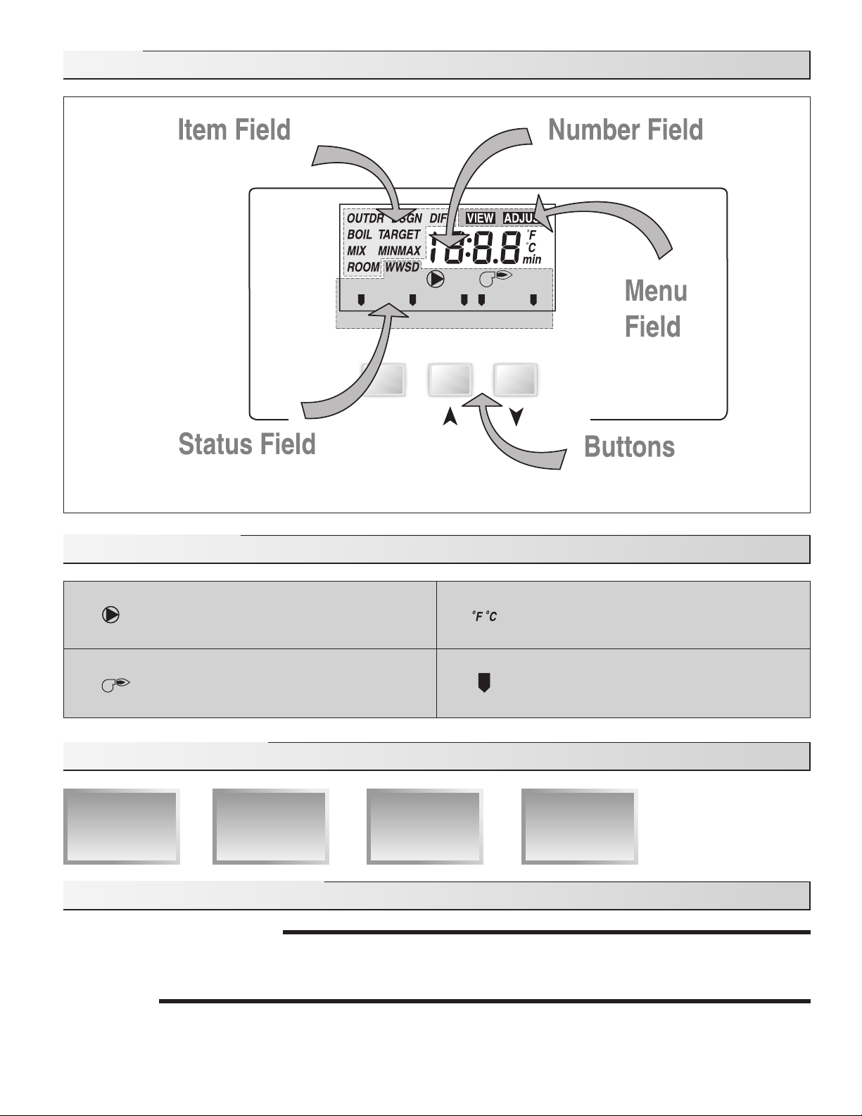
User Interface
The control uses a Liquid Crystal Display (LCD) as the method of supplying information. The LCD is used in order to setup and monitor
the operation of the system. The control has three push buttons (Item, , ) for selecting and adjusting settings. As the control is
programmed, record the settings in the Adjust menu table, which is found in the second half of this manual.
Item
The abbreviated name of the selected item will be displayed in the item field of the
display. To view the next available item, press and release the Item button. Once the last
available item in a menu has been reached, pressing and releasing the Item button will
return the display to the first item in the selected menu.
Adjust
To make an adjustment to a setting in the control, press all 3 buttons for 1 second (the
Item, and buttons). The display will then show the word ADJUST in the top right
corner. Then select the desired item using the Item button. Finally, use the and/or
button to make the adjustment.
To exit the ADJUST menu, leave the adjustment buttons alone for 20 seconds.
When the Item button is pressed and held in the VIEW menu, the display scrolls through all the adjust items.
Additional information can be gained by observing the status field and pointers of the LCD. The status field will indicate which of
the control’s outputs are currently active. Most symbols in the status field are only visible when the VIEW menu is selected.
2 of 60
Page 3
Display
Displa
y
s the
cur
r
ent
menu
Displa
y
s an abbre
viat
e
d
name of the sele
cted item
Displa
y
s the
cur
r
ent v
alue
of the sele
cted item
Displa
y
s the
cur
r
ent s
t
atus of
the
contr
ol's i
nputs, ou
tputs a
nd oper
ation
Selects Menu
s, Items
and adjusts setti
ngs
Item
Monitor Delay Open Close
Demand
Symbol Description
Sequence of Operation
Section A
General
Operation
Page 3 - 4
Section A: General Operation
POWERING UP THE CONTROL
When the control is powered up with 120 V (ac), the control displays “rtc” for 2 seconds followed by the software version for 2
seconds. The control then enters the normal operating mode
OPERATION
The control operates a floating action actuator motor connected to a 3-way or 4-way valve to control the boiler return water
temperature to prevent flue gas condensation and thermal shock. The control can also be used to provide outdoor reset or a fixed
setpoint temperature to the supply water temperature.
Pump
Displays when the boiler recirculating pump is
in operation.
Burner
Displays when the boiler relay is turned on.
Section B
Control
Operation
Page 4 - 5
Section C
Control
Settings
Page 5 - 6
°F, °C
Displays the unit of measure that all of the
temperatures are to be displayed in the
control.
Pointer
Displays the control is operating as indicated
by the text.
Section D
Temperature
Monitoring
Page 6
3 of 60
Page 4

Fixed PointFixed Point
By Changing
the Mix Design
and the Outdoor
Design settings
the Reset Ratio
changes.
By Changing
the Mix Design
and the Outdoor
Design settings
the Reset Ratio
changes.
70˚F
70˚F
Outdoor Reset
When the outdoor design (OUTDR DSGN) setting is set to a temperature, the control calculates a mix supply temperature based
on the outdoor air temperature and the programmed reset ratio. An outdoor sensor and a mix supply sensor must be installed.
Setpoint Control
When the outdoor design (OUTDR DSGN) setting is set to OFF, and there is a mix supply sensor installed, the control supplies a
fixed mix supply temperature equal to the MIX TARGET setting. An outdoor sensor is not required during this mode of operation.
No Diverting Valve
If a diverting valve is not installed, the outdoor design (OUTDR DSGN) is set to OFF. The boiler return sensor must be installed
to provide monitoring of the boiler conditions.
Floating Action
A 24 V (ac) floating action actuator motor is connected directly to the control on the R, R and N terminals (9, 10 and 11). The
R on terminal 9 is used to open the 3-way diverting valve to the system. The valve can open either in the clockwise or the
counterclockwise direction depending on the orientation of the valve. The R on terminal 10 is used to close the valve. The control
pulses the actuating motor to open or close to maintain the correct mixed supply water temperature at the mix sensor when
there is a heat demand. A visual indication as to whether the control is currently opening or closing the 3-way diverting valve is
displayed in the LCD.
Boiler Protection
The control is capable of providing boiler protection from cold return water temperatures. If the boiler sensor temperature is
cooler than the BOIL MIN setting while the boiler is firing, the control reduces the output to the 3-way diverting valve. This limits
the amount of cool return water to the boiler and allows the boiler temperature to recover. This feature can only be used if a 3-way
diverting valve is installed.
Exercising
The control has a built-in exercising function. If the boiler recirculating pump or valve has not been operated at least once every
3 days, the control turns on the output for a minimum of 10 seconds. This minimizes the possibility of a pump or valve seizing
during a long period of inactivity. The control ensures that the diverting valve operates over its entire range at least once each
exercising period. While the control is exercising, the Test LED flashes.
Note: The exercising function does not work if power to the control, pump, or valve is disconnected.
Section B: Control Operation
HEAT DEMAND
A heat demand is required in order for the control to provide heat by firing the boiler and opening the 3-way diverting valve. To
generate a heat demand, apply between 24 and 240 V (ac) across the Heat Demand terminals (1 and 2). Once voltage is applied,
the Demand pointer is displayed in the LCD.
When the heat demand is removed, the 3-way diverting valve is fully closed before the control is allowed to register a new heat
demand. The Demand pointer will be displayed whenever voltage is present on the Heat Demand terminals, even if the heat
demand is not registered. The 3-way diverting valve is closed to ensure the boiler is protected in the next boiler cycle.
Optionally, the control can be set up to target a setpoint mix supply temperature or outdoor reset temperature through the diverting
valve.
OUTDOOR RESET RATIO
When the control is used as a mixing reset control, the control uses
an outdoor sensor to measure the outdoor temperature. The reset
ratio increases the mix water temperature for every degree the outdoor
temperature falls. The slope of the reset ratio determines the rate at
which the temperature increases with falling outdoor temperatures.
The reset ratio is adjustable using the mix design (MIX DSGN) and the
outdoor design (OUTDR DSGN) settings.
4 of 60
Page 5

MIX TARGET
Parallel Shift
Using the
ROOM Setting
Parallel Shift
Using the
ROOM Setting
upup
downdown
6060
-40-40-20-20002020404060608080
8080
100100
120120
140140
160160
180180
200200
Mix
Design
Mix
Design
Mix
Maximum
Mix
Maximum
Mix
Minimum
Mix
Minimum
Outdoor
Design
Outdoor
Design
FixedFixed
Outdoor TemperatureOutdoor Temperature
Supply Water TemperatureSupply Water Temperature
WWSDWWSD
When used as a mixing reset control, the MIX TARGET temperature is calculated from the reset ratio and outdoor air temperature.
When used as a setpoint control, the installer sets the MIX TARGET temperature. The control displays the temperature that it is
currently trying to maintain as the mix supply temperature. If the control does not have a heat demand,”– – –” is displayed as the
MIX TARGET.
BOILER RECIRCULATING PUMP
The boiler recirculating pump contact (Boil Pmp, terminal 5) closes whenever there is a registered heat demand and the control is
not in warm weather shut down (WWSD). The boiler recirculating pump segment is displayed in the LCD. When the heat demand
is satisfied, the control continues to operate the boiler recirculating pump for the purge time. The diverting valve remains open
at the current setting during the purge time and will modulate to protect the boiler. Once the purge time has expired, the boiler
recirculating pump shuts off and the valve closes. If at any time the boiler return temperature falls below 135°F (57°C), the purge is
canceled. During the WWSD, the control exercises the pump for 10 seconds every 3 days of no activity.
Section C: Control Settings
OUTDOOR RESET SETTINGS
Note: For single boiler installations only. When multiple boilers are installed, use an appropriate staging control for outdoor reset
functions.
Room
The ROOM setting is the desired room temperature in the heating zone.
The ROOM setting provides a method to parallel shift the reset ratio
so that higher (or lower) mix water target temperatures are available
over the entire reset range. Adjusting the ROOM setting increases or
decreases the heat delivery to the building.
Mixing Design (MIX DSGN)
The MIX DSGN temperature is the supply water temperature required
to heat the mixing zones when the outdoor air temperature is as cold as the OUTDR DSGN Setting.
Outdoor Design (OUTDR DSGN)
The OUTDR DSGN is the outdoor air temperature that is the typical coldest temperature of the year where the building is located.
This temperature is used when doing the heat loss calculations for the building. If a cold outdoor design temperature is selected,
the mix supply temperature rises gradually as the outdoor temperature drops. If a warm outdoor design temperature is selected,
the mix supply temperature rises rapidly as the outdoor temperature drops.
Warm Weather Shut Down (WWSD)
When the outdoor air temperature rises above the WWSD setting, the control turns on the WWSD segment in the display. When
the control is in WWSD, the Demand pointer is displayed, if there is a demand. However, the control does not operate the heating
system to satisfy this demand. If the control is in setpoint mode, the WWSD feature is not functional.
Mixing Minimum (MIX MIN)
The MIX MIN is the lowest temperature that the control is allowed
to use as a mix target temperature. During mild conditions, if the
control calculates a mix target temperature that is below the MIX MIN
setting, the mix target temperature is adjusted to match the MIX MIN
setting. During this condition, the MIN segment will be displayed in
the LCD when either the MIX TARGET or MIX temperature is being
viewed.
Mixing Maximum (MIX MAX)
The MIX MAX sets the highest water temperature that the control
is allowed to calculate as the mix target temperature. If the control
does target the MIX MAX setting, and the MIX temperature is near
the MIX MAX, the MAX segment will be displayed in the LCD while
either the MIX TARGET temperature or the MIX temperature is
being viewed.
5 of 60
Page 6
SETPOINT OPERATION
Monitor
Monitor
Monitor
Mix Target
For setpoint control, set the OUTDR DSGN to OFF. The mix target becomes the setpoint supply temperature that the control is
to maintain. The mix target temperature is set by the installer in the ADJUST menu. An outdoor sensor is not required during this
mode of operation.
COMMON SETTINGS
The following settings are common to both the outdoor reset and setpoint operations.
Open Delay
The open delay is the amount of time that the actuating motor requires to operate the valve from fully closed to fully open.
Boiler Minimum (BOIL MIN)
Most boilers require a minimum water temperature in order to prevent flue gas condensation. The BOIL MIN adjustment is set to
the boiler’s minimum recommended operating temperature. The lowest boiler minimum temperature is 135°F (57°C).
Boiler Minimum Delay (BOIL MIN Delay)
The boiler minimum delay allows a time for the boiler temperature to rise to the boiler minimum temperature while there is a heat
demand. After the time delay, the control begins to count the boiler minimum run time (Monitor BOIL MIN run).
Pump Delay
The pump delay allows the boiler recirculating pump to purge heat from the boiler into the system after the heat demand is
removed. The amount of purge time is determined by the Pump Delay setting.
Section D: Temperature Monitoring
Boiler Temperature (BOIL)
The actual boiler return temperature as measured by the boiler return sensor.
Mix Target
The current mix target temperature if outdoor reset or setpoint operation is selected.
Mix
The actual mix temperature as measured by the mix supply sensor if a mix supply sensor is installed.
Outdoor
The current outdoor temperature as measured by the outdoor sensor, if the outdoor sensor is installed and Outdoor Design is
set to a temperature.
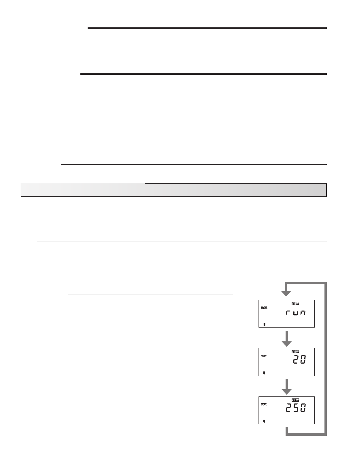
Monitor Items
Monitor Items are displayed using a five digit number. The display cycles between the
monitor name, the first two digits, and the last three digits.
Boiler Run Time (Monitor BOIL run)
The control records the number of hours the boiler enable contact has been closed.
Number of Boiler Cycles (Monitor BOIL CYC)
The control records the number of cycles of the boiler enable contact.
Boiler Run Time Below Return Water Minimum (Monitor BOIL MIN run)
The control records the number of hours the boiler return temperature is below the
boiler minimum temperature and the boiler enable contact is closed. The control does
not record any time while the control is within the boiler minimum delay period.
Number of Boiler Cold Shock Conditions (Monitor BOIL CS)
The control records the number of large and quick temperature swings, which could
be an indication of erratic system behavior.
Boiler Sensor Error Time (Monitor BOIL MIN Err)
The control records the number of hours the boiler return sensor is not functioning.
6 of 60
Page 7

Installation
Caution
Improper installation and operation of this control could result in damage to the equipment and possibly even personal injury. It is the
installer’s responsibility to ensure that this control is safely installed according to all applicable codes and standards. This electronic
control is not intended for uses as a primary limit control. Other controls that are intended and certified as safety limits must be placed
into the control circuit. Do not open the control. Refer to qualified personnel for servicing. Opening voids warranty and could result in
damage to the equipment and possibly even personal injury.
STEP ONE
Check the contents of this package. If any of the contents listed are missing or damaged, please contact your wholesaler or
Burnham representative for assistance.
Burnham RTC includes: Burnham Return Temperature Control, Return Temperature Control manual, 1 boiler return
sensor, 4 #8-32 x ½” Phillips screws.
STEP TWO
A. Return Temperature Control (RTC) – Mount the control to the boiler front jacket panel at the top right. See Figures 1 and 2
for general component placement. The RTC mounting bracket must be attached to the jacket first, using four (4) #8 x ¾” drill point
sheet metal screws. Before attaching the RTC to the mounting bracket, remove the controller from the control base/wiring chamber
by pressing the tab on the base and pulling the controller up and off. (This is to prevent accidental damage to the controller during
the mounting process.) One may find it easier to install some of the conduit connectors, along with their corresponding conduit
runs, onto the RTC control base/wiring chamber before mounting it to the bracket. Before choosing which wiring knockouts to
use, read Step Four. Mount the control base/wiring chamber to the bracket using the four (4) #8-32 x ½” Phillips pan head screws
supplied with the RTC. Then reattach the RTC controller to the control base.
B. Return Sensor – The return water temperature sensor must be mounted in a special 3”NPT x 12” long nipple with ¼” NPT side
tapping supplied by Burnham. Apply pipe dope to special nipple both threaded ends and mount the nipple into the boiler’s right
rear return port (as viewed from the rear of the boiler), so that nipple side tapping end is positioned away from the boiler. Apply pipe
dope to the sensor threads and install the sensor into the nipple ¼” NPT side tapping making sure the connection is watertight. Use
bell reducer (refer to Figure 3 or Figure 4) to adapt to recommended return piping size. See Figure 3 or 4 (depending on the boiler
being installed) for the proper location of the return nipple. See Figure 2 for return sensor wiring details. Run the sensor wiring to a
suitable junction box, using a grommet to protect the leads as they enter the box. Mount the junction box to the boiler’s rear jacket
panel, as shown in Figure 2. Connect the sensor wiring from the junction box to the RTC control at the front of the boiler, using the
appropriate conduit and connectors.
INSTALLING THE CONTROL AND RELATED COMPONENTS
GETTING READY
C. Diverting Valve and Actuator – A diverting 3-way or 4-way valve must be installed in the boiler loop piping in order for the RTC
to provide boiler protection. Only a Burnham-approved valve and actuator may be used with the RTC. The diverting valve sizing
depends upon the designed boiler delta T. See Appendix B for proper valve selection. The valve actuator is mounted to the top of
the diverting valve. Position the valve so that the actuator is not on the underside of the valve. Mount and connect the actuator as
illustrated in Appendix C. The electrical connections depend on the valve orientation.
D. Boiler Circulator – A properly selected boiler circulator will maintain a constant and minimum flow through the boiler during
each heat demand. The appropriate circulator must be selected, based upon the designed boiler delta T. See Appendix B for
appropriate boiler circulator selections for 20°F and 40°F delta T applications.
WARNING: IF THE SELECTED BOILER CIRCULATOR IS GREATER THAN 1/3 HP, AN ISOLATION RELAY MUST BE ADDED
WHEN USING THE RTC. IF A 3-PHASE BOILER CIRCULATOR OR A CIRCULATOR WITH AN AMP DRAW GREATER THAN 10
AMP IS SELECTED, AN APPROPRIATE MOTOR STARTER MUST BE USED.
STEP THREE
When using the RTC control, the boiler loop piping must contain the boiler, the boiler circulator, a 3-way or 4-way diverting valve,
and the return sensor. The boiler loop injects hot water into the primary loop, provided that the boiler return water temperature
(measured by the return sensor) is at least 135°F. If the return temperature is below 135°F, the diverting valve closes, recirculating
boiler supply water through the boiler loop until the return water has been heated to at least 135°F. The RTC controls the diverting
value actuator based upon the absolute return water temperature, as well as the rate of temperature change.
Several typical RTC applications are shown in Appendix A. Select the appropriate application before proceeding.
See Figures 5 and 6 for general component and piping arrangements when using 3-way and 4-way diverting valves. See Figure
3 for V9A piping recommendations for 3-way valve applications. See Figure 4 for V11 piping recommendations for 3-way valve
applications. As shown in these diagrams, the boiler loop’s supply and return are connected to the primary loop through two closely
spaced tees, at a maximum branch centerline distance of four times the primary loop diameter (4 x D Max).
NEAR BOILER PIPING
7 of 60
Page 8
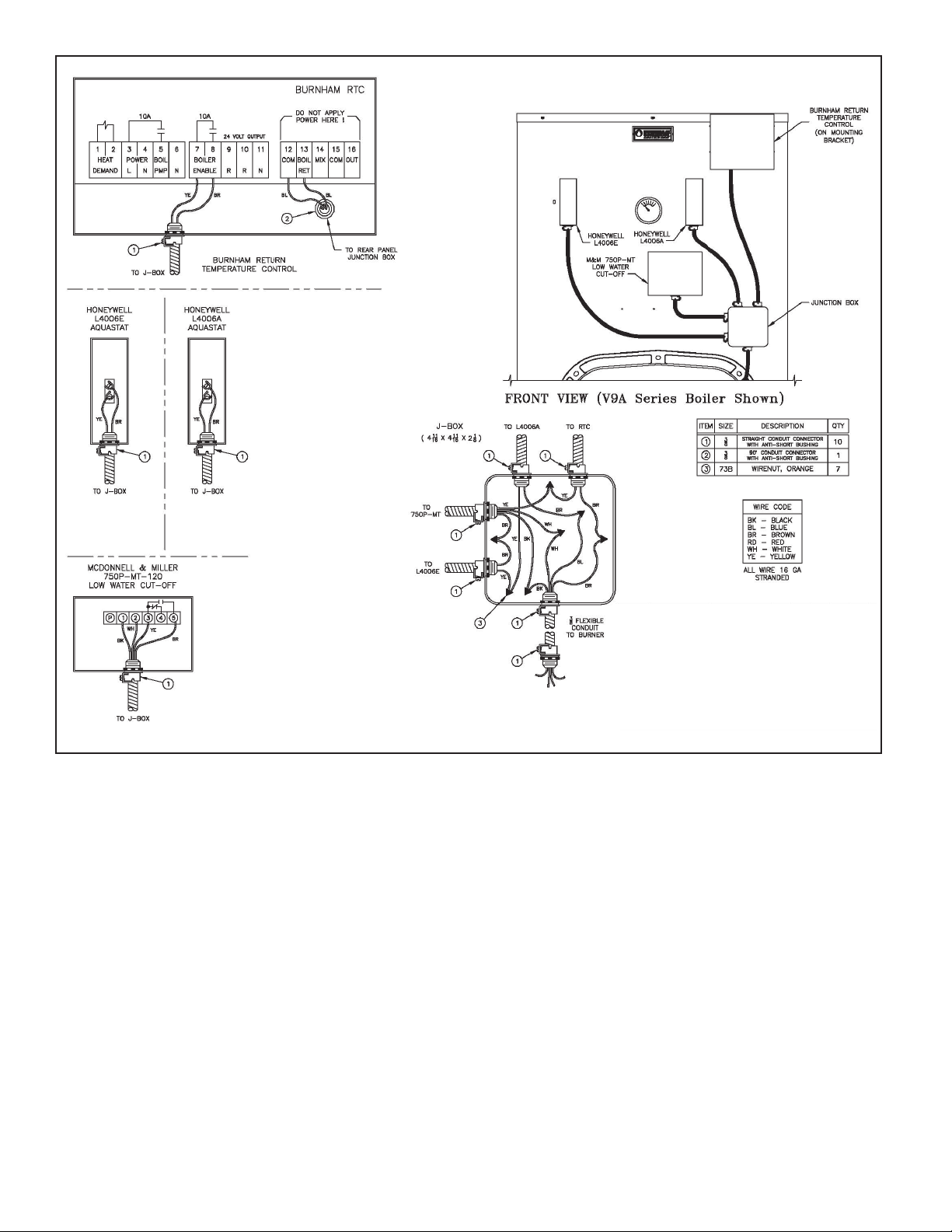
Figure 1: Typical Boiler Wiring With RTC (Front)
8 of 60
Page 9
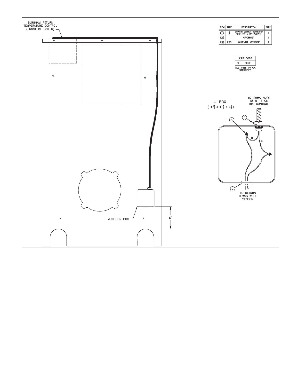
Figure 2: Typical Boiler Wiring With RTC Return Sensor (Rear)
9 of 60
Page 10
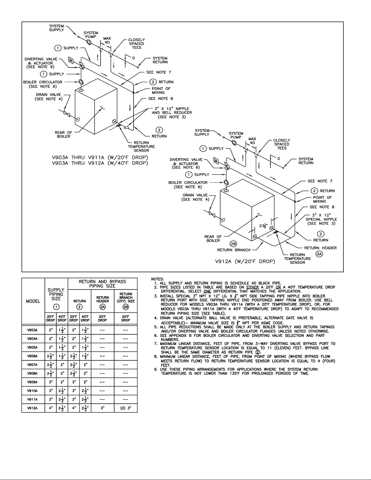
Figure 3: V9A Series Boiler Recommended Minimum Piping
- RTC With 3-Way Diverting Valve
10 of 60
Page 11
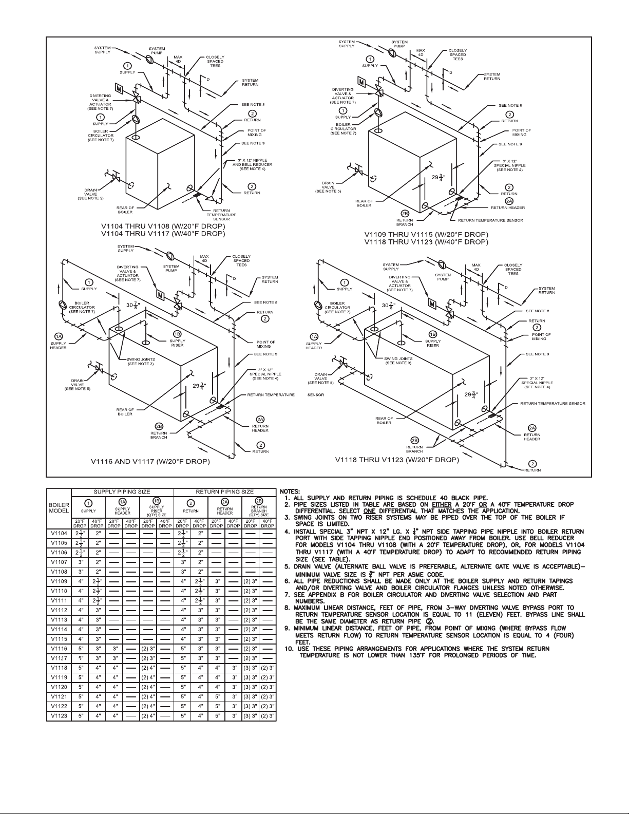
Figure 4: V11 Series Boiler Recommended Minimum Piping
- RTC With 3-Way Diverting Valve
11 of 60
Page 12
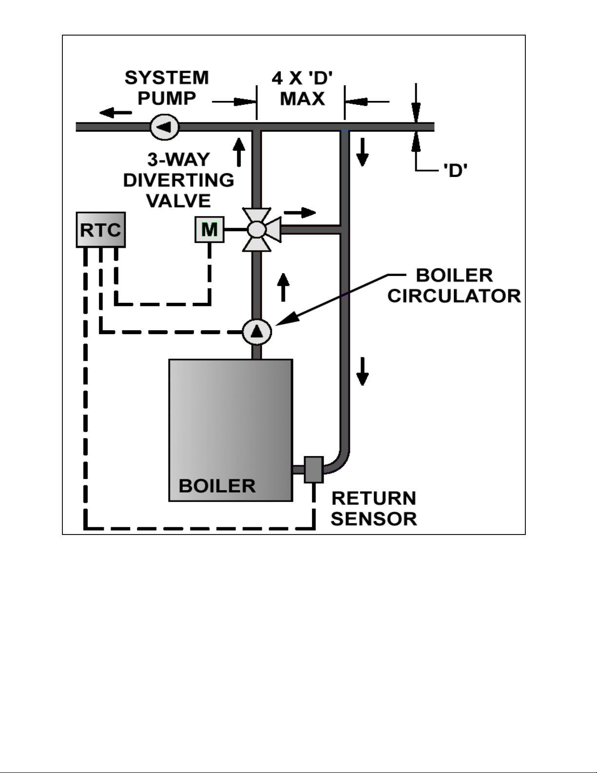
Figure 5: Typical Burnham Boiler Loop w/3-Way Diverting
Valve
12 of 60
Page 13
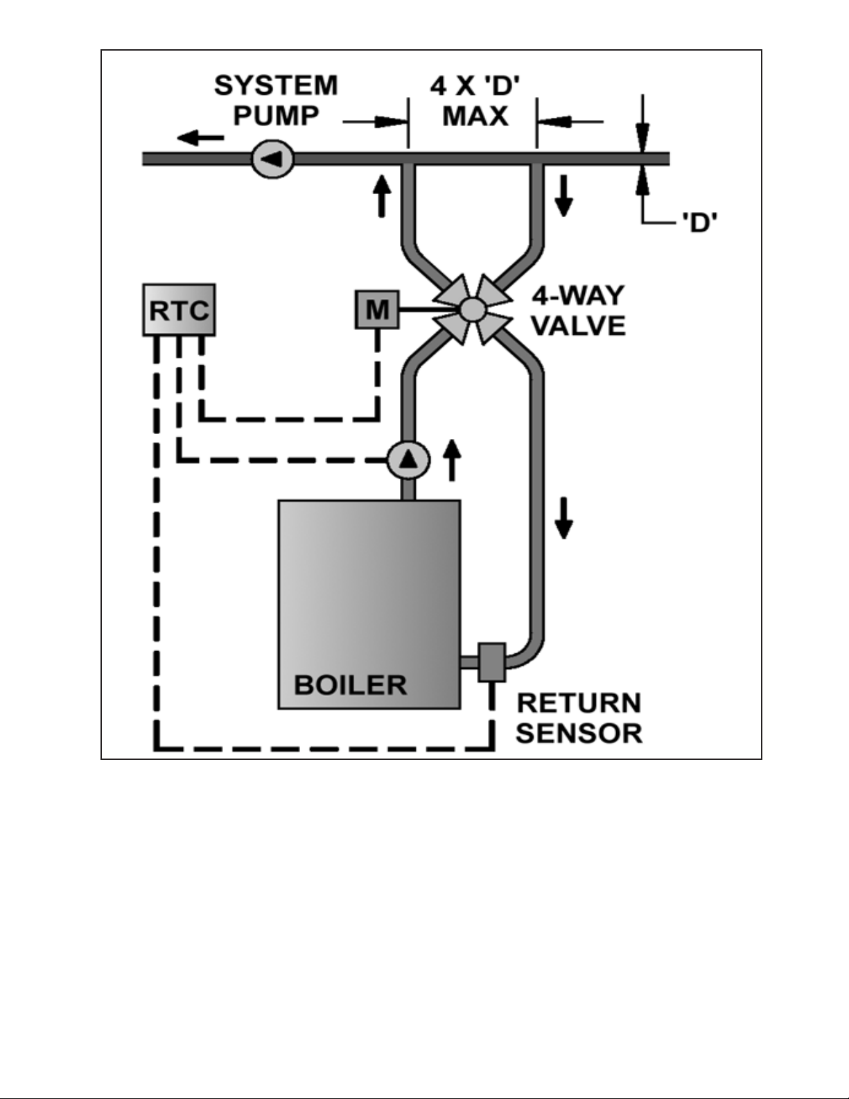
Figure 6: Typical Burnham Boiler Loop w/4-Way Diverting
Valve
13 of 60
Page 14

On multiple boiler applications, each boiler is installed in the same arrangement as a single boiler application. Each boiler loop contains
5
Boil
Pm
p
Po
we
r
6
N
3
L
120 V (ac)
N
L
4
N
1
Heat
Demand
2
24 to 240 V (ac)
N
L
Po
we
r
4
120 V (ac)
L
N
3
its own boiler circulator, diverting valve and actuator, RTC control, and return sensor. A number of different boiler sequencers can be
used in conjunction with the RTC by energizing the control’s heat demand circuit. The RTC control’s outdoor reset feature cannot be
used on multiple boiler installations. The sequencer’s outdoor reset feature (if available) would have to be utilized instead.
STEP FOUR
ROUGH-IN WIRING
All electrical wiring terminates in the control base wiring chamber. The base has standard 7/8” (22 mm) knockouts, which accept
common wiring hardware and conduit fittings. Before removing the knockouts, check the wiring diagram and select those sections
of the chamber with common voltages. Do not allow the wiring to cross between sections, as the wires will interfere with safety
dividers, which should be installed at a later time.
Power must not be applied to any of the wires during the rough-in wiring stage.
- All wires are to be stripped to a length of 3/8 in (9 mm) to ensure proper connection to the control.
- If a Mix Sensor 071 or an Outdoor Sensor 070 is used, install the sensor according to the installation instructions in the Data
Brochure D 070 and run the wiring back to the control.
- Make sure the Boiler Return Sensor is installed and run the wiring back to the control.
- Run wire from other system components (pumps, boilers, etc.) to the control.
- Run wires from the 120 V (ac) power to the control. Ideally, a separate dedicated circuit should power the control.
- Use a clean power source with a 15 A circuit to ensure proper operation. Multi-strand 16 AWG wire is recommended for all
120 V (ac) wiring due to its superior flexibility and ease of installation into the terminals.
STEP FIVE
ELECTRICAL CONNECTIONS TO THE CONTROL
The installer should test to confirm that no voltage is present at any of the wires. Push the control into the base and slide it down
until it snaps firmly into place.
Powered Input Connections
120 V (ac) Power
Connect the 120 V (ac) power supply to the Power L and Power N terminals (3 and 4).
This connection provides power to the microprocessor and display of the control. As
well, this connection provides power to the Boil Pmp terminal (5). The control should
be powered from a dedicated circuit. This avoids power disruption to the control in
the event of failure on another electrical device on the same circuit. DO NOT power
the control from the boiler or burner circuit, since there may be times where the
boiler or burner circuit may be switched off in the summer. This would prevent the
exercising of the boiler recirculating pump and the diverting valve. Boiler protection
for dormant boilers, in a multiple boiler application, will not be possible if the control
is not powered.
Heat Demand
To generate a heat demand, a voltage between 24 V (ac) and 240 V (ac) must be
applied across the Heat Demand terminals (1 and 2).
Output Connections
Boiler Recirculating Pump Contact (Boil Pmp)
The Boil Pmp output terminal (5) on the control is a powered output. When the relay in
the control closes, 120 V (ac) is provided to the Boil Pmp terminal (5) from the Power L
terminal (3). To operate the boiler recirculating pump, connect one side of the boiler
recirculating pump circuit to terminal (5), and the second side of the pump circuit to
the neutral (N) terminal (6).
14 of 60
Page 15
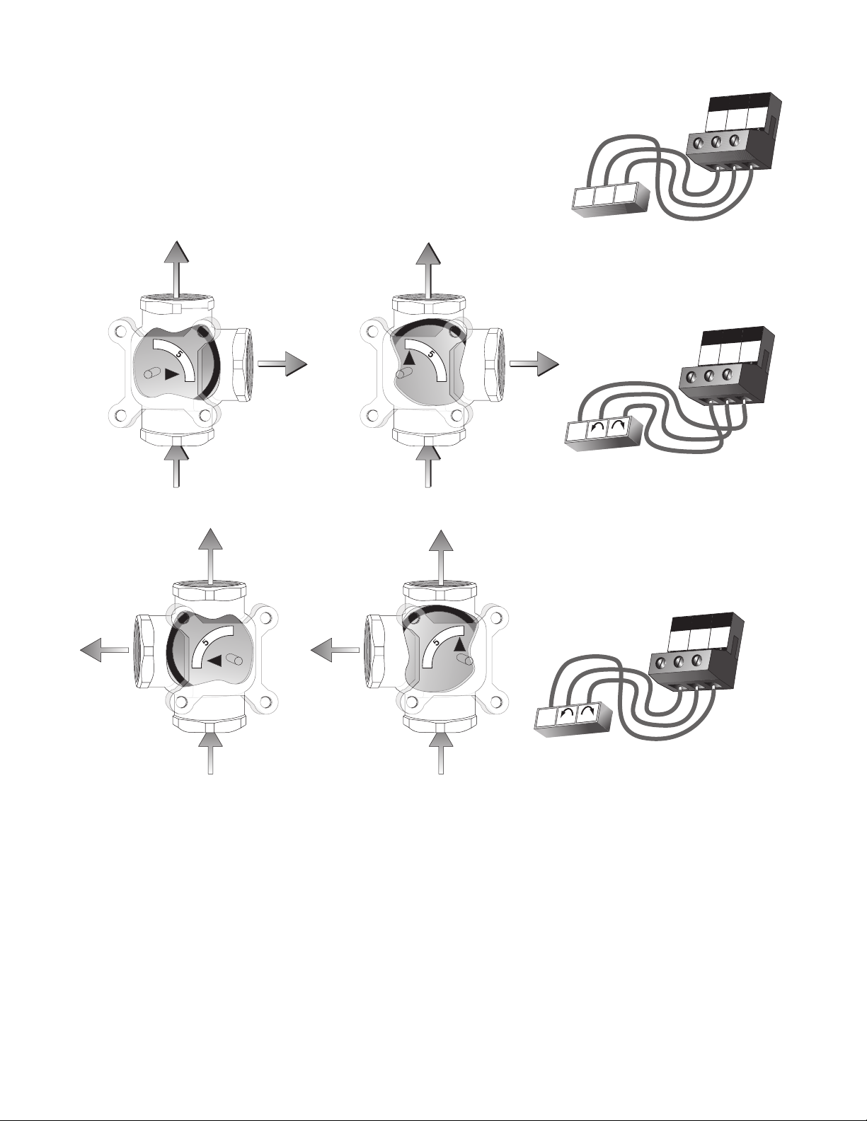
Diverting Valve Actuator
Supply
from
Boiler
No Flow
to
System
Full
Flow
thru
Bypass
No
Flow
thru
Bypass
COUNTER CLOCKWISE (CCW) = OPEN TO SYSTEM
CLOCKWISE (CW) = CLOSED TO SYSTEM
Supply
from
Boiler
Full Flow
to
System
RTC Terminals
Actuator Terminals
9
R
10
R
11
N
L1
N
L1
0
0
9
R
10
R
11
N
Open
N
Close
24 Volt Output
Supply
from
Boiler
0
5
10
No Flow
to
System
RTC Terminals
Actuator Terminals
Full
Flow
thru
Bypass
CLOCKWISE (CW) = OPEN TO SYSTEM
COUNTER CLOCKWISE (CCW) = CLOSED TO SYSTEM
Supply
from
Boiler
Full Flow
to
System
No
Flow
thru
Bypass
0
5
10
9
R
10
R
11
N
L
1
N
L1
Terminals 9, 10 and 11 are powered with 24 V (ac) from the control.
There is no need to provide a separate 24 V (ac) power source for
the diverting valve actuator. R (9) is connected to the open terminal
of the actuating motor and R (10) is connected to the close terminal
of the actuating motor. N (11) is then connected to the common
terminal of the actuating motor.
The control’s Test Sequence can be used to check the motor circuit. Once the Test button is pressed, the valve should move to
the fully open position. If the motor closes instead of opening, the wiring of the actuating motor must be reversed. Next, the valve
should move to the fully closed position. If it does not, check the wiring between the terminals and the actuating motor. Refer to
any installation or troubleshooting information supplied with the motor.
15 of 60
Page 16
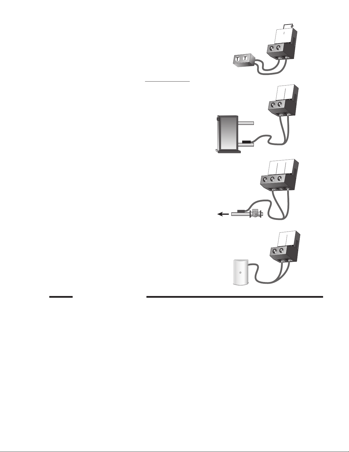
Boiler Enable Contact
7
Boiler
Enable
8
12
Com
13
Boil
Re
t
Boiler
Sensor
12
Com
13
Boil
Re
t
14
Mi
x
Mix Supply
Sensor
System
Pump
15
Com
16
Out
The Boiler Enable terminals (7 and 8) are an isolated output in the
control. There is no power available on these terminals from the
control. These terminals are to be used as a switch to either make
or break the boiler limit circuit. When the control requires the boiler
to fire, it closes the contact between terminals 7 and 8.
Sensor and Unpowered Input Connections
Do not apply power to these terminals, as this will damage the control.
Boiler Return Sensor
Connect the two wires from the Boiler Return Sensor to the Com
and Boil Ret terminals (12 and 13). The boiler return sensor is used
by the control to measure the boiler return temperature.
Mix Sensor (Outdoor Reset and Setpoint Modes)
Connect the two wires from the Mix Sensor 071 to the Com and Mix
terminals (12 and 14). The mix sensor is used by the control to measure the mixed supply water temperature in the primary loop. Typically the sensor is attached to the pipe downstream of the system
pump.
Outdoor Sensor (Outdoor Reset Mode)
Connect the two wires from the Outdoor Sensor 070 to the Com and
Out terminals (15 and 16). The outdoor sensor is used by the control
to measure the outdoor air temperature.
STEP SIX
Each terminal block must be unplugged from its header on the control before power is applied for testing. To remove the terminal
block, pull straight down from the control.
The following tests are to be performed using standard testing practices and procedures and should only be carried out by properly
trained and experienced persons.
A good quality electrical test meter, capable of reading from at least 0 – 300 V (ac) and at least 0 – 2,000,000 Ohms, is essential to
properly test the wiring and sensors.
TESTING THE WIRING
16 of 60
Page 17
13
14
15
Boi
l
Re
t
Mi
x
Co
m
12
Co
m
2
Heat
Demand
1
V
20 to 260 V (ac)
4
N
Po
w
er
3
L
V
108 to 132 V (ac)
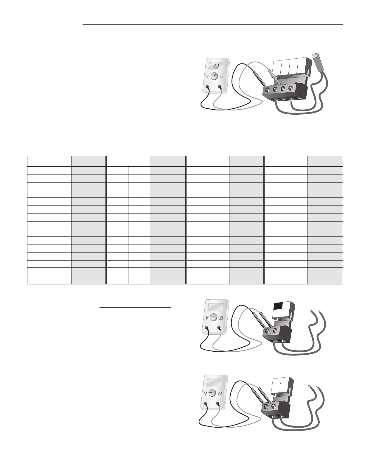
Test the Sensors
A good quality test meter capable of measuring up to 2,000,000 Ω (1kΩ = 1000 Ω) is required to measure the sensor resistance.
In addition to this, the actual temperature should be measured with a good quality digital thermometer.
First measure the temperature using the thermometer.
Then measure the resistance of the sensor at the control.
The wires from the sensor must not be connected to the
control while the test is performed. Using the chart below,
estimate the temperature measured by the sensor. The
sensor and thermometer readings should be close. If the
test meter reads a very high resistance, there may be
a broken wire, a poor wiring connection or a defective
sensor. If the resistance is very low, the wiring may be
shorted, there may be moisture in the sensor or the
sensor may be defective. To test for a defective sensor,
measure the resistance directly at the sensor location.
Do not apply voltage to a sensor at any time as damage
to the sensor may result.
Temperature
°F
-50
-45
-40
-35
-30
-25
-20
-15
-10
-5
0
5
10
15
°C
-46
-43
-40
-37
-34
-32
-29
-26
-23
-21
-18
-15
-12
-9
Resistance
Ω
490,813
405,710
336,606
280,279
234,196
196,358
165,180
139,402
118,018
100,221
85,362
72,918
62,465
53,658
Temperature
°F
°C
20
25
30
35
40
45
50
55
60
65
70
75
80
85
Resistance
-7
-4
-1
2
4
7
10
13
16
18
21
24
27
29
Test the Power Supply
Make sure exposed wires and bare terminals are not in
contact with other wires or grounded surfaces. Turn on
the power and measure the voltage between the Power
L and Power N terminals (3 and 4) using an AC voltmeter,
the reading should be between 108 and 132 V (ac).
Ω
46,218
39,913
34,558
29,996
26,099
22,763
19,900
17,436
15,311
13,474
11,883
10,501
9,299
8,250
Temperature
°F
90
95
100
105
110
115
120
125
130
135
140
145
150
155
°C
32
35
38
41
43
46
49
52
54
57
60
63
66
68
Resistance
Ω
7,334
6,532
5,828
5,210
4,665
4,184
3,760
3,383
3,050
2,754
2,490
2,255
2,045
1,857
Temperature
°F
160
165
170
175
180
185
190
195
200
205
210
215
220
225
°C
71
74
77
79
82
85
88
91
93
96
99
102
104
107
Resistance
Ω
1,689
1,538
1,403
1,281
1,172
1,073
983
903
829
763
703
648
598
553
Test the Powered Inputs
Heat Demand
Measure the voltage between the Heat Demand
terminals (1 and 2). When the heat demand device
calls for heat, between 20 and 260 V (ac) should be
measured at the terminals. When the heat demand
device is off, less than 5 V (ac) should be measured.
17 of 60
Page 18
Test the Outputs
4
5
6
Boi
l
Pm
p
Po
we
r
N
3
L
120 V (ac)
Boiler Recirculating
Pump
N
L
N
14
13
15
12
16
Com
Com
Out
Boil
Re
t
Mix
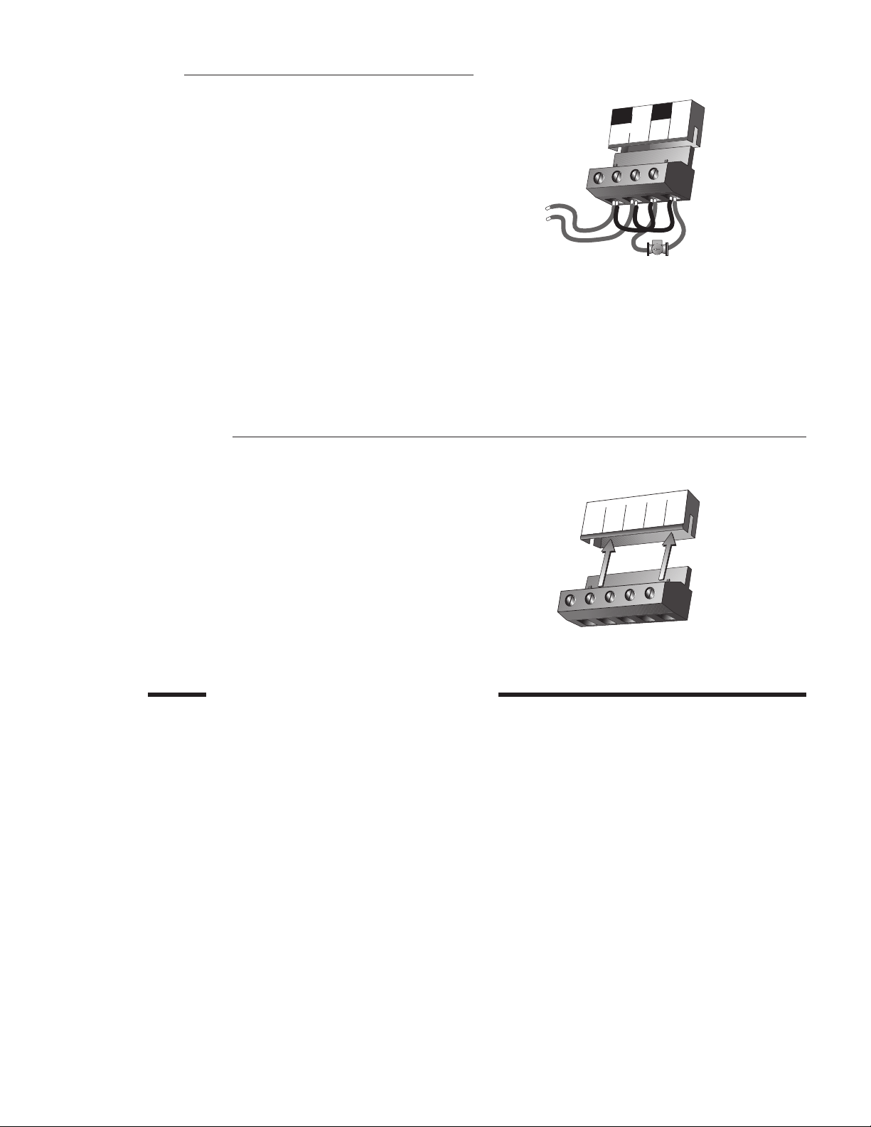
Boiler Recirculating Pump (Boil Pmp)
The boiler recirculating pump is connected to the Boil Pmp
terminal (5). Make sure that power to the terminal block is off,
and install a jumper between the Power L and the Boil Pmp
terminals (3 and 5). Install a second jumper between Power N
and N terminals (4 and 6). When power is applied to the Power
L and Power N terminals (3 and 4), the boiler recirculating
pump should start. If the pump does not turn on, check the
wiring between the terminal block and pump, and refer to any
installation or troubleshooting information supplied with the
pump. If the pump operates properly, disconnect the power
and remove the jumpers.
Boiler Enable Contact
If the boiler limit circuit is connected to the Boiler Enable terminals (7 and 8), make sure power to the boiler circuit is off, and
install a jumper between the terminals. When the boiler limit circuit is powered up, the boiler should fire. If the boiler does not
turn on, refer to the installation or troubleshooting information supplied with the boiler. Check for proper operation of each
device in the boiler limit circuit. If the boiler operates properly, disconnect the power and remove the jumper.
Connecting the Control
Make sure all power to the devices and terminal blocks is off, and remove any remaining jumpers from the terminals.
Reconnect the terminal blocks to the control by carefully aligning
them with their respective headers on the control, and then pushing
the terminal blocks into the headers. The terminal blocks should
snap firmly into place.
Install the supplied safety dividers between the unpowered sensor
inputs and the powered or 120 V (ac) wiring chambers.
Apply power to the control. The operation of the control on power up
is described in the Sequence of Operation section of this manual.
STEP SEVEN
ADJUSTING THE CONTROL SETPOINTS
In order for the RTC to function properly, several control settings must be adjusted. Review the “User Interface” and “Sequence
of Operation” sections of this manual for descriptions of each setting and instructions on how to adjust them. Adjust the following settings as specified:
A. ROOM (Room Temperature) – Set the desired room temperature.
B. MIX TARGET – This setting can only be used on applications where the mix sensor is installed. When the outdoor reset
feature is not selected, this setting represents the fixed target supply water temperature. On this type of application, the MIX
TARGET setting should be adjusted to match the boiler operating aquastat’s setpoint temperature.
C. MIX DSGN (Mixing Design) – When the outdoor reset feature is selected, this setting represents the design system supply
water temperature. If unsure about the original design temperature, set the MIX DSGN to match the boiler operating aquastat’s
setpoint temperature.
D. OUTDR DSGN (Outdoor Design) – When the outdoor reset feature is selected, this setting represents the typical coldest
temperature of the year in the area where the installation is located. If this value is unknown, use the temperature value found
in ASHRAE Fundamentals for the area closest to the installation.
18 of 60
Page 19

E. WWSD (Warm Weather Shut Down) – This feature is only used when the outdoor reset feature is selected. Set the WWSD
as desired, keeping in mind that, when the outdoor air temperature rises above the WWSD setting, the control will not operate the
boiler to satisfy any demands for heat.
F. MIX MIN (Mixing Minimum) – When the outdoor reset feature is selected, this setting represents the minimum mix target
supply water temperature. Set as desired.
G. MIX MAX (Mixing Maximum) – When the outdoor reset feature is selected, this setting represents the maximum allowable
mix target supply water temperature. Typically, this is set between 200°F and 220°F. However, the MIX MAX setting must below the
highest permissible temperature for any system component affected by the boiler supply water.
H. OPEN DELAY – This setting represents the number of seconds required for the actuator to move the valve from a fully
closed to a fully open position. Keep this setting at the default value of 50 seconds.
I. BOIL MIN (Boiler Minimum) – This setting represents the minimum allowable boiler return water temperature. Keep this
setting at 135°F, unless a higher minimum return water temperature is required.
J. BOIL MIN DELAY (Boiler Minimum Delay) – This setting represents the number of seconds required for warm-up during
an initial cold start. Use the appropriate value from Table I or II, depending on the specific application. (These values include 90
seconds of pre-purge time.)
K. PUMP DELAY – This setting represents the time (in seconds) for boiler circulator (pump) purge after a heat demand cycle.
This minimizes the amount of boiler temperature overshoot at the end of a cycle. During the pump purge, the diverting valve will continue to operate and prevent low temperature return water from entering the boiler. At the end of the pump purge period, the diverting
valve will close immediately. Set the pump delay as desired. (The default setting is 30 seconds.)
STEP EIGHT
The control’s exterior can be cleaned using a damp cloth. Moisten the cloth with water and wring out prior to wiping control. Do not
use solvents or cleaning solutions.
CLEANING THE CONTROL
19 of 60
Page 20

View Menu (1 of 1)
Monitor
Monitor
Monitor
Monitor
Monitor
Display Description
Section
BOIL
D
Current boiler return temperature as measured by the boiler sensor.
MIX TARGET
Target mixed supply is the temperature the control is currently trying to maintain
D
at the mixing sensor.
(Mix sensor is present or OUTDR DSGN = OFF)
MIX
Current mixed supply water temperature as measured by the mixing sensor.
D
(Mix sensor is present or OUTDR DSGN = OFF)
OUTDR
Current outdoor air temperature as measured by the outdoor sensor.
D
(Outdoor sensor is present and OUTDR DSGN ≠ OFF)
Monitor BOIL run
The control records the number of hours the boiler enable contact has been
D
closed.
Range
14 to 266°F
(-10 to 130°C)
– – –, 14 to 266°F
(– – –,-10 to 130°C)
14 to 266°F
(-10 to 130°C)
-67 to 149°F
(-55 to 65°C)
run <> 0 to 99 999
Monitor BOIL CYC
D
The control records the number of boiler enable relay cycles.
Monitor BOIL MIN run
D
Below return water minimum. The control records the number of hours the boiler
operates below the boiler minimum setting.
Monitor BOIL CS
D
The number of times the boiler has experienced cold shock conditions.
Monitor BOIL MIN Err
D
The number of hours the boiler return sensor is not functioning.
CYC <> 0 to 99 999
run <> 0 to 99 999
CS <> 0 to 99 999
Err <> 0 to 99 999
20 of 60
Page 21

Adjust Menu (1 of 1)
Delay Open
Delay
Delay
Display Description
Section
Range
Actual
Setting
ROOM
C
The desired room air temperature.
(OUTDR DSGN ≠ OFF)
MIX TARGET
C
Mixing setpoint temperature.
(OUTDR DSGN = OFF)
MIX DSGN
The design supply water temperature used in the heat loss
C
calculation for the heating system.
(OUTDR DSGN ≠ OFF)
OUTDR DSGN
The design outdoor air temperature used in the heat loss calculation
C
for the heating system. For setpoint operation, set the OUTDR
DSGN to OFF
WWSD
The system’s warm weather shut down during the occupied (Day)
C
period.
MIX MIN
C
The minimum supply temperature for the mixing system.
(OUTDR DSGN ≠ OFF)
35 to 100°F
(2 to 38°C)
Default = 70°F (21°C)
60 to 200°F
(16 to 93°C)
Default = 180°F (82°C)
70 to 210°F
(21 to 99°C)
Default = 180°F (82°C)
-60 to 32°F, OFF
(-51 to 0°C, OFF)
Default = OFF
35 to 100°F, OFF
(2 to 38°C, OFF)
Default = 70°F (21°C)
OFF, 35 to 150°F
(OFF, 2 to 66°C)
Default = OFF
MIX MAX
C
The maximum supply water temperature for the mixing system.
(OUTDR DSGN ≠ OFF)
Open Delay
C
The time the actuating motor requires to operate from fully closed
to fully open.
BOIL MIN
C
The minimum boiler return water temperature.
BOIL MIN Delay
C
The amount of time the boiler requires to heat up to the boiler
minimum temperature from a cold start.
Pump Delay
C
The amount of time the boiler recirculating pump purges the boiler.
Temperature Units
The units of measure that all of the temperatures are to be displayed
C
in the control.
80 to 220°F
(27 to 104°C)
Default = 200°F (93°C)
30 to 230 seconds
Default = 50 seconds
135 to 230°F
(57 to 110°C)
Default = 135°F (57°C)
210 to 540 seconds
(10 second increments)
Default = 540 seconds
0 to 240 seconds
Default = 30 seconds
°F, °C
Default = °F
21 of 60
Page 22

Testing the Control
Test
The control has a built-in test routine, which is used to test the main control functions. The
control continually monitors the sensors, and displays an error message whenever a fault is
found. See the following pages for a list of the control’s error messages and possible causes.
When the Test button is pressed, the test light is turned on. The individual outputs and relays
are tested in the following test sequence.
TEST SEQUENCE
Each step in the test sequence lasts at least 10 seconds.
During the test routine, the test sequence may be paused by pressing the Test button. Only if there is a heat demand can the control
be paused in a step. If the Test button is not pressed again for 5 minutes while the test sequence is paused, the control exits the
entire test routine. If the test sequence is paused, the Test button can be pressed again to advance to the next step. This can also
be used to rapidly advance through the test sequence. To reach the desired step, repeatedly press and release the Test button
until the appropriate device and segment in the display turn on.
Step 1 -The diverting valve is run fully open.
Step 2 -The diverting valve is run fully closed.
Step 3 -The boiler recirculating pump (Boil Pmp) is turned on and waits 10 seconds.
Step 4 -The Boiler Enable contact is turned on for 10 seconds. After 10 seconds, the Boiler Enable and Boil Pmp contacts are shut off.
Step 5 -The test sequence is completed and the control resumes its normal operation.
Troubleshooting
When troubleshooting any heating system, it is always a good idea to establish a set routine to follow. By following a consistent
routine, many hours of potential headaches can be avoided. Below is an example of a sequence that can be used when diagnosing
or troubleshooting problems in a hydronic heating system.
Establish the problem. Get as much information from the customer as possible about the problem. Is there
Establish the
Problem
Understanding
the Sequence of
Operation
Use the Test
Routine
Sketch the
Piping in the
System
too much heat, not enough heat, or no heat? Is the problem only in one particular zone or area of the
building, or does the problem affect the entire system? Is this a consistent problem or only intermittent?
How long has the problem existed for? This information is critical in correctly diagnosing the problem.
Understand the sequence of operation of the system. If a particular zone is not receiving enough heat,
which pumps or valves in the system must operate in order to deliver heat to the affected zone? If the
zone is receiving too much heat, which pumps, valves, or check valves must operate in order to stop the
delivery of heat?
Press the Test button on the control and follow the control through the test sequence as described
in the Testing section. Pause the control as necessary to ensure that the correct device is operating
as it should.
Sketch the piping of the system. This is a relatively simple step that tends to be overlooked, however, it
can often save hours of time in troubleshooting a system. Note flow directions in the system paying close
attention to the location of pumps, check valves, pressure bypass valves, and diverting valves. Ensure
correct flow direction on all pumps. This is also a very useful step if additional assistance is required.
Document the control for future reference. Before making any adjustments to the control, write down
Document the
Control
22 of 60
all of the items that the control is currently displaying. This includes items such as error messages,
current temperatures and settings, and which devices should be operating as indicated by the LCD. This
information is an essential step if additional assistance is required to diagnose the problem.
Page 23

Isolate the
Problem
Test the Contacts,
Voltages and
Sensors
Error Messages
Isolate the problem between the control and the system. Now that the sequence of operation is known and
the system is sketched, is the control operating the proper pumps and valves at the correct times? Is the
control receiving the correct signals from the system as to when it should be operating? Are the proper
items selected in the menus of the control for the device that is to be operated?
Test the contacts, voltages and sensors. Using a multimeter, ensure that the control is receiving adequate
voltage to the power terminals and the demand terminals as noted in the technical data. Use the
multimeter to determine if the internal contacts on the control are opening and closing correctly. Follow
the instructions in the Testing the Wiring section to simulate closed contacts on the terminal blocks as
required. Test the sensors and their wiring as described in the Test the Sensors section.
The control was unable to read a piece of information from its EEPROM. This error can be caused by
a noisy power source. The control will load the factory defaults and continue operation if possible. All
settings in the Adjust menu must be reviewed before the error will clear.
The control is no longer able to read the boiler sensor due to a short circuit. The control will continue
to enable the boiler and will operate the diverting valve at 30% output while there is a heat demand
and until the sensor problem is repaired. The control will also record the time without the boiler return
sensor. Locate and repair the problem as described in the Test the Sensors section. To clear the error
message from the control after the sensor has been repaired, press the Item button.
The control is no longer able to read the boiler sensor due to an open circuit. The control will continue
to enable the boiler and will operate the diverting valve at 30% output while there is a heat demand
and until the sensor problem is repaired. The control will also record the time without the boiler return
sensor. Locate and repair the problem as described in the Test the Sensors section. To clear the error
message from the control after the sensor has been repaired, press the Item button.
The control is no longer able to read the mix supply sensor due to a short circuit. In this case the control
will operate the diverting valve at 30% output as long as there is a heat demand and until the sensor
problem is repaired. Locate and repair the problem as described in the Test the Sensors section. To
clear the error message from the control after the sensor has been repaired, press the Item button.
The control is no longer able to read the mix supply sensor due to an open circuit. In this case the
control will operate the diverting valve at 30% output as long as there is a heat demand and until
the sensor problem is repaired. Locate and repair the problem as described in the Test the Sensors
section. To clear the error message from the control after the sensor has been repaired, press the Item
button. Note: If a diverting valve is not installed, set the outdoor design (OUTDR DSGN) setting to
OFF, power off the control and then re-power.
The control is no longer able to read the outdoor sensor due to a short circuit. In this case the control
targets the design mix supply temperature and continues operation. Locate and repair the problem as
described in the Test the Sensors section. To clear the error message from the control after the sensor
has been repaired, press the Item button.
The control is no longer able to read the outdoor sensor due to an open circuit. In this case the control
targets the design mix supply temperature and continues operation. Locate and repair the problem as
described in the Test the Sensors section. To clear the error message from the control after the sensor
has been repaired, press the Item button. Note: If a diverting valve is operated as a setpoint control,
set the outdoor design (OUTDR DSGN) setting to OFF.
23 of 60
Page 24

STRAPCTR relioB/ytQ
traP
rebmuN
swercsgnitnuomdnarosnesreliobhtiw)CTR(lortnoCerutarepmeTnruteR 1 61906108
.3598F560#ssofnaD,rotomdnoceS05,V42,M29EBSE,rotoMlortnoC 1 55306108
21-52GMledoM;TPN"1-8698B560#ssofnaD,evlaVgnitreviDyaW-3 1 31094108
8-23GMledoM;TPN"4/1-1-9698B560#ssofnaD,evlaVgnitreviDyaW-3 1 65306108
831GledoM;TPN"2/1-1-3598B560#ssofnaD,evlaVgnitreviDyaW-3 1 75306108
151GledoM;TPN"2-4598B560#ssofnaD,evlaVgnitreviDyaW-3 1 85306108
05-561FledoM;degnalf"2/1-2-0698B560#ssofnaD,evlaVgnitreviDyaW-3 1 95306108
561FledoM;degnalf"2/1-2-1698B560#ssofnaD,evlaVgnitreviDyaW-3 1 06306108
081FledoM;degnalf"3-2698B560#ssofnaD,evlaVgnitreviDyaW-3 1 16306108
0011FledoM;degnalf"4-3698B560#ssofnaD,evlaVgnitreviDyaW-3 1 26306108
5211FledoM;degnalf"5-4698B560#ssofnaD,evlaVgnitreviDyaW-3 1 36306108
21-52GM4ledoM;TPN"1-5898B560#ssofnaD,evlaVgnitreviDyaW-4 1 61094108
8-23GMledoM;TPN"4/1-1-6898B560#ssofnaD,evlaVgnitreviDyaW-4 1 71094108
834GledoM;TPN"2/1-1-9798B560#ssofnaD,evlaVgnitreviDyaW-4 1 42094108
154GledoM;TPN"2-0898B560#ssofnaD,evlaVgnitreviDyaW-4 1 52094108
054FledoM;degnalf"2/1-2-0516B560#ssofnaD,evlaVgnitreviDyaW-4 1 66306108
564FledoM;degnalf"2/1-2-5616B560#ssofnaD,evlaVgnitreviDyaW-4 1 62094108
084FledoM;degnalf"3-0816B560#ssofnaD,evlaVgnitreviDyaW-4 1 84306108
0014FledoM;degnalf"4-0026B560#ssofnaD,evlaVgnitreviDyaW-4 1 46306108
5214FledoM;degnalf"5-5226B560#ssofnaD,evlaVgnitreviDyaW-4 1 56306108
elppinlaicepsnidetnuomebot;daeL"23htiwssarB,TPN"4/1,rosneSrelioB 1 51906108
04HCS,dnEmorF"3TPN"4/1,laicepS,"21X"3,elppiN 1 624006608
seireS11V&9V,)CTR(lortnoCerutarepmeTnruteRroftekcarBgnitnuoM 1 4306107
relioB11V&9V,srosneSxiMdnateseRroodtuOsseL,tiKtiforteRmetsySCTR 1 5806106
relioB11V&9V,srosneSxiMdnateseRroodtuOhtiW,tiKtiforteRmetsySCTR 1 6806106
gnitnuomepipecafrusrofdael"01,rosneSerutarepmeTdiulFlasrevinU170#ramket,rosneSxiM 1 37106108
070#ramket,rosneSriAroodtuO 1 27106108
P300#ramket,lioCtloV42,yaleR 1 69106108
P400#ramket,lioCtloV021,yaleR 1 56106108
TPN"Ω2xegnalf"Ω2;tiKegnalFyaW-3 1 07806106
TPN"3xegnalf"3;tiKegnalFyaW-3 1 17806106
TPN"4xegnalf"4;tiKegnalFyaW-3 1 27806106
TPN"5xegnalf"5;tiKegnalFyaW-3 1 37806106
egnalfdlewnopils"4xegnalf"4;tiKegnalFyaW-3 1 47806106
egnalfdlewnopils"5xegnalf"5;tiKegnalFyaW-3 1 57806106
Repair Parts
24 of 60
Page 25

This page has intentionally been left blank.
25 of 60
Page 26

Appendix A: Application Drawings
120 V (ac)
24 V (ac)
Class II
Transformer
RTC
Outdoor Sensor
(S3) 070
M
Z3
V2
Boiler Return
Sensor
(S1) 071
P1
M
Z1
P2
M
Z2
S2
4D Max
V1
C1
M1
A1. 3-way RTC in Primary/Secondary - Heating Only/No DHW; with/without Outdoor Reset (Mechanical)
C1 = Diverting Valve Actuator
M1 = By-Pass Mix Point
P1 = Boiler Circulator
P2 = System Pump (runs on call for heat)
S1 = Boiler Return Sensor
S2 = Mix Supply Sensor 071 (Required for Reset
or Set-point Control)
S3 = Outdoor Sensor 070 (Required for Reset
Control)
V1 = 3-Way Diverting Valve
V2 = Ball Valve, Balancing Valve
Z1...Z3 = Zones
NOTES:
1) Install the boiler as indicated above for systems where return temperatures may be less than 135F and heating
application only.
2) The Outdoor Sensor (S3) and the Mix Supply Sensor (S2) are required when the Outdoor Reset feature is selected. The
mix sensor must be installed 10 pipe diameters downstream of the system pump, in the primary loop. The mix sensor must be
secured to the surface of the pipe using a wire tie or similar device.
3) The by-pass piping, diverting valve and boiler circulator must be sized using the sizing charts found in Appendix B.
4) Closely spaced tees must connect the branch to the larger header. The Tee centerlines must be no greater than 4 times the
larger header pipe diameter.
5) The diverting valve, V1, must be no greater than 11 linear feet of pipe from the Return Sensor, S1.
6) There shall be a MINIMUM of 4 linear feet of pipe between the By-pass Mix Point, M1, and the Return Sensor, S1.
7) The balancing valve in the boiler return line, V2, may be necessary in low head by-pass loop applications.
8) Expansion tanks, air scoops and other components left out for clarity.
9) Observe all applicable plumbing and electrical codes.
This diagram is for reference only. The installer or designer is responsible for the proper selection and design of the
system.
26 of 60
Page 27

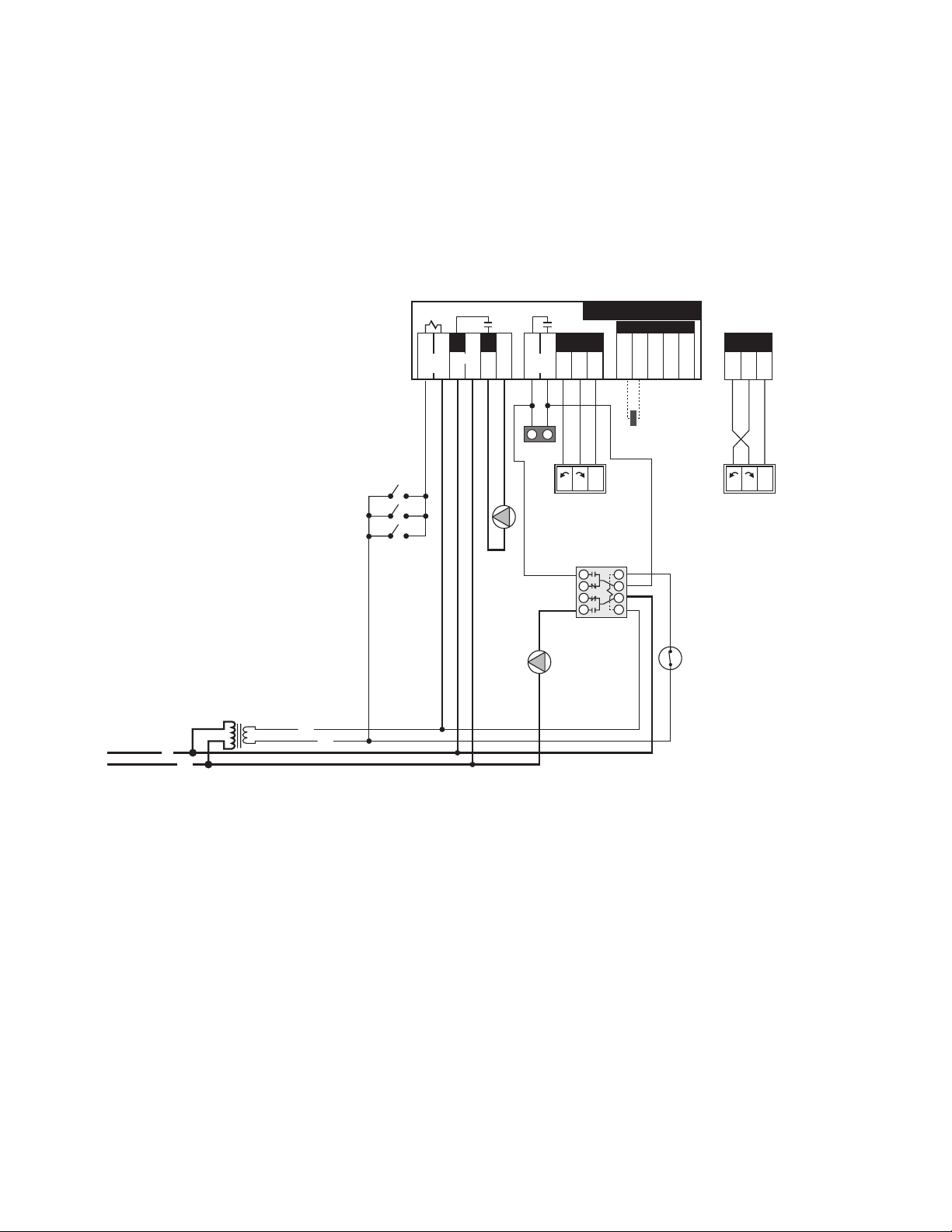
A1. 3-way RTC in Primary/Secondary - Heating Only/No DHW; with/without Outdoor Reset (Electrical)
C
24 V (ac)
R
N
120 V (ac)
Class II
Transformer
L
S1
S2 S3
Do not apply power
10A
Boil
Ret
Com Mix OutCom
L
12 13 14 15 16
Boil
Pmp N
6
Burnham RTC
3 5
R
9
R
10
N
11
N
4
Power
10A
24 Volt Output
7 8
Boiler
Enable
1 2
Heat
Demand
P1
Boiler
C1
CW - Closed to System
C1
CW - Open to System
NL1 L1
Z1...Z3
R
9
R
10
N
11
24 Volt Output
NL1 L1
C1 = Mixing Valve Actuating Motor
P1 = Boiler Circulator
S1 = Boiler Return Sensor
S2 = Mix Supply Sensor 071
S3 = Outdoor Sensor 070
Z1...Z3 = Zone Valves, Zone Relays,
Thermostats or BMS Signal
NOTES:
1) Refer to the I&O to determine correct valve orientation and actuator wiring.
2) 120 VAC supplying the RTC should be separate from the burner/boiler circuit.
3) Heat demand can be any electrical signal consisting of 24 - 240 VAC.
4) Use isolation relays for circulators greater than 1/3 HP. Use motor starters for 3 phase circulators.
5) The Outdoor Sensor (S3) and the Mix Supply Sensor (S2) are required if the Outdoor Reset feature is selected.
6) System Pump (P2) to be operated by zone relay or other installer supplied device.
This diagram is for reference only. The installer or designer is responsible for the proper selection and design of the
system.
27 of 60
Page 28

A2. 3-way RTC in Primary/Secondary - Heating and DHW using Tankless Coil; with/without Outdoor Reset
120 V (ac)
24 V (ac)
Class II
Transformer
RTC
Outdoor Sensor
(S3) 070
V2
Boiler Return
Sensor
(S1) 071
A1
P2
A1
COLD
Water
IN
HOT
Water
OUT
P1
M
Z3
M
Z1
P3
M
Z2
S2
4D Max
V1
C1
M1
R2
R1
ST1
(Mechanical)
A1 = Tankless Coil or Storage Tank Aquastat
C1 = Mixing Valve Actuating Motor
M1 = By-Pass Mix Point
P1 = Boiler Circulator
P2 = Tankless System Circulator
P3 = System Pump (runs on call for heat)
R1 = Relay (Required with and without priority)
R2 = Relay (Required for Priority)
S1 = Boiler Return Sensor
S2 = System Mix Sensor 071
S3 = Outdoor Sensor 070
ST1= Storage Tank
TK1= Tankless Coil
V1 = 3-Way Diverting Valve
V2 = Ball Valve, Balancing Valve
Z1...Z3 = Zones
NOTES:
1) Install the boiler as indicated above for systems where return temperatures may be less than 135F and heating/DHW
with tankless coils..
2) The Outdoor Sensor (S3) and the Mix Supply Sensor (S2) are required when the Outdoor Reset feature is selected.
The mix sensor must be installed 10 pipe diameters downstream of the system pump, in the primary loop. The mix sensor
must be secured to the surface of the pipe using a wire tie or similar device.
3) The by-pass piping, diverting valve and boiler circulator must be sized using the sizing charts found in Appendix B.
4) Closely spaced tees must connect the branch to the larger header. The Tee centerlines must be no greater than 4
times the larger header pipe diameter.
5) The diverting valve, V1, must be no greater than 11 linear feet of pipe from the Return Sensor, S1.
6) There shall be a MINIMUM of 4 linear feet of pipe between the By-pass Mix Point, M1, and the Return Sensor, S1.
7) The balancing valve in the boiler return line, V2, may be necessary in low head by-pass loop applications.
8) Domestic Hot Water must be tempered for safe usage. The tankless aquastat and/or storage tank aquastat (A1) are
normally closed switches. Circuit breaks on temperature rise.
9) Expansion tanks, air scoops and other components left out for clarity.
10) Observe all applicable plumbing and electrical codes.
This diagram is for reference only. The installer or designer is responsible for the proper selection and design
of the system.
28 of 60
Page 29

C
24 V (ac)
R
N
120 V (ac)
Class II
Transformer
L
S1
S2 S3
Do not apply power
10A
Boil
Ret
Com Mix OutCom
L
12 13 14 15 16
Boil
Pmp N
6
Burnham RTC
3 5
R
9
R
10
N
11
N
4
Power
10A
24 Volt Output
7 8
Boiler
Enable
1 2
Heat
Demand
P1
Boiler
C1
CW - Closed to System
C1
CW - Open to System
NL1 L1
Z1...Z3
R
9
R
10
N
11
24 Volt Output
NL1 L1
2
1
8
7
3
4
5
6
S1
S2 S3
Do not apply power
10A
Boil
Ret
Com Mix OutCom
L
12 13 14 15 16
Boil
Pmp N
6
Burnham RTC
3 5
R
9
R
10
N
11
N
4
Power
10A
24 Volt Output
7 8
Boiler
Enable
1 2
Heat
Demand
P1
Boiler
C1
CW - Open to System
NL1 L1
Z1...Z3
R
9
R
10
N
11
24 Volt Output
NL1 L1
P2
A1
2
1
8
7
3
4
5
6
2
1
8
7
3
4
5
6
Breaks on
Temp. Rise
A1
Breaks on
Temp. Rise
P2
C1
CW - Close
to System
R1
R1
R2
A2. 3-way RTC in Primary/Secondary - Heating and DHW using Tankless Coil; with/without Outdoor Reset
(Electrical)
A1 = Tankless Coil or Storage Tank
Aquastat
C1 = Mixing Valve Actuating Motor
P1 = Boiler Circulator
P2 = Tankless Coil System Circulator
R1 = Relay (Required with and
without priority)
R2 = Relay (Required for priority)
S1 = Boiler Return Sensor
S2 = Mix Supply Sensor 071
S3 = Outdoor Sensor 070
Z1...Z3 = Zone Valves, Zone Relays,
Thermostats or BMS Signal
NOTES:
1) Refer to the I&O to determine correct valve orientation and actuator wiring.
2) 120 VAC supplying the RTC should be separate from the burner/boiler circuit.
3) Heat demand can be any electrical signal consisting of 24 - 240 VAC.
4) Use isolation relays for circulators greater than 1/3 HP. Use motor starters for 3 phase circulators.
5) The Outdoor Sensor (S3) and the Mix Supply Sensor (S2) are required if the Outdoor Reset feature is selected.
6) Connect the tankless aquastat (A1) if you are not using a storage tank. If you are using a storage tank with the tankless
heater, use the storage tank aquastat.
7) System Pump (P3) to be operated by zone relay or other installer supplied device.
This diagram is for reference only. The installer or designer is responsible for the proper selection and design
of the system.
29 of 60
Page 30

A3. 3-way RTC in Primary/Secondary - Heating and DHW using Indirect Water Heater; with/without
120 V (ac)
24 V (ac)
Class II
Transformer
RTC
Outdoor Sensor
(S3) 070
M
Z3
V2
Boiler Return
Sensor
(S1) 071
P1
M
Z1
P3
M
Z2
S2
4D Max
V1
C1
M1
A1
P2
R1
R2
Indirect
DHW
Tank
Outdoor Reset (Mechanical)
A1 = Indirect Hot Water Aquastat
C1 = Diverting Valve Actuating Motor
M1 = By-Pass Mix Point
P1 = Boiler Circulator
P2 = Indirect Circulator
P3 = System Pump (runs on call for heat)
S1 = Boiler Return Sensor
S2 = Mix Supply Sensor 071 (Required for Reset
or Set-point Control)
S3 = Outdoor Sensor 070 (Required for Reset
Control)
V1 = 3-Way Diverting Valve
V2 = Ball Valve, Balancing Valve
Z1...Z3 = Zones
NOTES:
1) Install the boiler as indicated above for systems where return temperatures may be less than 135F and heating/DHW
with an indirect water heater.
2) The Outdoor Sensor (S3) and the Mix Supply Sensor (S2) are required when the Outdoor Reset feature is selected.
The mix sensor must be installed 10 pipe diameters downstream of the system pump, in the primary loop. The mix sensor
must be secured to the surface of the pipe using a wire tie or similar device.
3) The by-pass piping, diverting valve and boiler circulator must be sized using the sizing charts found in Appendix B.
4) Closely spaced tees must connect the branch to the larger header. The Tee centerlines must be no greater than 4
times the larger header pipe diameter.
5) The diverting valve, V1, must be no greater than 11 linear feet of pipe from the Return Sensor, S1.
6) There shall be a MINIMUM of 4 linear feet of pipe between the By-pass Mix Point, M1, and the Return Sensor, S1.
7) The balancing valve in the boiler return line, V2, may be necessary in low head by-pass loop applications.
8) The indirect heater aquastat (A1) is a normally closed switch. Circuit breaks on temperature rise.
9) Expansion tanks, air scoops and other components left out for clarity.
10) Observe all applicable plumbing and electrical codes.
This diagram is for reference only. The installer or designer is responsible for the proper selection and design
of the system.
30 of 60
Page 31

A3. 3-way RTC in Primary/Secondary - Heating and DHW using Indirect Water Heater; with/without
C
24 V (ac)
R
N
120 V (ac)
Class II
Transformer
L
S1
S2 S3
Do not apply power
10A
Boil
Ret
Com Mix OutCom
L
12 13 14 15 16
Boil
Pmp N
6
Burnham RTC
3 5
R
9
R
10
N
11
N
4
Power
10A
24 Volt Output
7 8
Boiler
Enable
1 2
Heat
Demand
P1
Boiler
C1
CW - Closed to System
C1
CW - Open to System
NL1 L1
Z1...Z3
R
9
R
10
N
11
24 Volt Output
NL1 L1
2
1
8
7
3
4
5
6
S1
S2 S3
Do not apply power
10A
Boil
Ret
Com Mix OutCom
L
12 13 14 15 16
Boil
Pmp N
6
Burnham RTC
3 5
R
9
R
10
N
11
N
4
Power
10A
24 Volt Output
7 8
Boiler
Enable
1 2
Heat
Demand
P1
Boiler
C1
CW - Open to System
NL1 L1
Z1...Z3
R
9
R
10
N
11
24 Volt Output
NL1 L1
P2
A1
2
1
8
7
3
4
5
6
2
1
8
7
3
4
5
6
Breaks on
Temp. Rise
A1
Breaks on
Temp. Rise
P2
C1
CW - Close
to System
R1
R1
R2
Outdoor Reset (Mechanical)
A1 = Indirect Hot Water Aquastat
C1 = Mixing Valve Actuating Motor
P1 = Boiler Circulator
P2 = Indirect Circulator
R1 = Relay (Required with and
without priority)
R2 = Relay (Required for priority)
S1 = Boiler Return Sensor
S2 = Mix Supply Sensor 071
S3 = Outdoor Sensor 070
Z1...Z3 = Zone Valves, Zone Relays,
Thermostats or BMS Signal
NOTES:
1) Refer to the I&O to determine correct valve orientation and actuator wiring.
2) 120 VAC supplying the RTC should be separate from the burner/boiler circuit.
3) Heat demand can be any electrical signal consisting of 24 - 240 VAC.
4) Use isolation relays for circulators greater than 1/3 HP. Use motor starters for 3 phase circulators.
5) The Outdoor Sensor (S3) and the Mix Supply Sensor (S2) are required if the Outdoor Reset feature is selected.
6) System Pump (P3) to be operated by zone relay or other installer supplied device.
This diagram is for reference only. The installer or designer is responsible for the proper selection and design
of the system.
31 of 60
Page 32

A4. 3-way RTC in Primary/Secondary - Heating and DHW using Indirect Water Heater on Primary Loop;
120 V (ac)
24 V (ac)
Class II
Transformer
RTC
V2
Boiler Return
Sensor
(S1) 071
P1
M
Z1
P3
M
Z2
4D Max
V1
C1
M1
A1
P2
R1
Indirect
DHW
Tank
V3
without Outdoor Reset (Mechanical)
A1 = Indirect Hot Water Aquastat
C1 = Diverting Valve Actuating Motor
M1 = By-Pass Mix Point
P1 = Boiler Circulator
P2 = Indirect Circulator
P3 = System Pump (runs on call for heat)
R1 = Relay
S1 = Boiler Return Sensor
V1 = 3-Way Diverting Valve
V2 = Ball Valve, Balancing Valve
V3 = Ball Valve, System Balancing
Z1...Z3 = Zones
NOTES:
1) Install the boiler as indicated above for systems where return temperatures may be less than 135F and heating/DHW
with an indirect water heater.
2) This arrangement is NOT recommended for outdoor reset applications. The reset temperature will constantly change
DHW water performance.
3) The by-pass piping, diverting valve and boiler circulator must be sized using the sizing charts found in Appendix B.
4) A domestic hot water priority could be used provided the diversion from the heating system loop does not impact the
system heater’s performance.
5) Closely spaced tees must connect the branch to the larger header. The Tee centerlines must be no greater than 4
times the larger header pipe diameter.
6) The diverting valve, V1, must be no greater than 11 linear feet of pipe from the Return Sensor, S1.
7) There shall be a MINIMUM of 4 linear feet of pipe between the By-pass Mix Point, M1, and the Return Sensor, S1.
8) The balancing valve in the boiler return line, V2, may be necessary in low head by-pass loop applications.
9) The indirect heater aquastat (A1) is a normally closed switch. Circuit breaks on temperature rise.
10) Expansion tanks, air scoops and other components left out for clarity.
11) Observe all applicable plumbing and electrical codes.
This diagram is for reference only. The installer or designer is responsible for the proper selection and design
of the system.
32 of 60
Page 33
A4. 3-way RTC in Primary/Secondary - Heating and DHW using Indirect Water Heater on Primary Loop;
C
24 V (ac)
R
N
120 V (ac)
Class II
Transformer
L
S1
Do not apply power
10A
Boil
Ret
Com Mix OutCom
L
12 13 14 15 16
Boil
Pmp N
6
Burnham RTC
3 5
R
9
R
10
N
11
N
4
Power
10A
24 Volt Output
7 8
Boiler
Enable
1 2
Heat
Demand
P1
Boiler
C1
CW - Closed to System
C1
CW - Open to System
NL1 L1
Z1...Z3
R
9
R
10
N
11
24 Volt Output
NL1 L1
2
1
8
7
3
4
5
6
P2
A1
Breaks on
Temp. Rise
R1
without Outdoor Reset (Electrical)
A1 = Indirect Hot Water Aquastat
C1 = Mixing Valve Actuating Motor
P1 = Boiler Circulator
P2 = Indirect Circulator
R1 = Relay
S1 = Boiler Return Sensor
Z1...Z3 = Zone Valves, Zone Relays,
Thermostats or BMS Signal
NOTES:
1) Refer to the I&O to determine correct valve orientation and actuator wiring.
2) 120 VAC supplying the RTC should be separate from the burner/boiler circuit.
3) Heat demand can be any electrical signal consisting of 24 - 240 VAC.
4) Use isolation relays for circulators greater than 1/3 HP. Use motor starters for 3 phase circulators.
5) System Pump (P3) to be operated by zone relay or other installer supplied device.
This diagram is for reference only. The installer or designer is responsible for the proper selection and design
of the system.
33 of 60
Page 34

A5. 4-way RTC in Primary/Secondary - Heating Only/No DHW; with/without Outdoor Reset (Mechanical)
120 V (ac)
24 V (ac)
Class II
Transformer
RTC
Outdoor Sensor
(S3) 070
P1
Boiler Return
Sensor
(S1) 071
M
V2
P2
S2
4D Max
M
Z3
P2
V1
M1
C1
S2
M
Z2
M
Z1
C1 = Diverting Valve Actuating Motor
M1 = By-Pass Mix Point
P1 = Boiler Circulator
P2 = System Pump (runs on call for heat)
S1 = Boiler Return Sensor
S2 = Mix Supply Sensor 071 (Required
for Reset Control)
S3 = Outdoor Sensor 070 (Required
for Reset Control)
V1 = 4-Way Diverting Valve
V2 = Ball Valve, Balancing Valve
Z1...Z3 = Zones
NOTES:
1) Install the boiler as indicated above for systems where return temperatures may be less than 135F and heating
application only.
2) The Outdoor Sensor (S3) and the Mix Supply Sensor (S2) are required when the Outdoor Reset feature is selected. The
mix sensor must be installed 10 pipe diameters downstream of the system pump, in the primary loop. The mix sensor must be
secured to the surface of the pipe using a wire tie or similar device.
3) The by-pass piping, diverting valve and boiler circulator must be sized using the sizing charts found in Appendix B.
4) Closely spaced tees must connect the branch to the larger header. The Tee centerlines must be no greater than 4 times the
larger header pipe diameter.
5) The diverting valve, V1, must be no greater than 11 linear feet of pipe from the Return Sensor, S1.
6) There shall be a MINIMUM of 4 linear feet of pipe between the By-pass Mix Point, M1, and the Return Sensor, S1.
7) The balancing valve in the boiler return line, V2, may be necessary in low head by-pass loop applications.
8) Expansion tanks, air scoops and other components left out for clarity.
9) Observe all applicable plumbing and electrical codes.
This diagram is for reference only. The installer or designer is responsible for the proper selection and design of the
system.
34 of 60
Page 35

C
24 V (ac)
R
N
120 V (ac)
Class II
Transformer
L
S1
S2 S3
Do not apply power
10A
Boil
Ret
Com Mix OutCom
L
12 13 14 15 16
Boil
Pmp N
6
Burnham RTC
3 5
R
9
R
10
N
11
N
4
Power
10A
24 Volt Output
7 8
Boiler
Enable
1 2
Heat
Demand
P1
Boiler
C1
CW - Closed to System
C1
CW - Open to System
NL1 L1
Z1...Z3
R
9
R
10
N
11
24 Volt Output
NL1 L1
A5. 4-way RTC in Primary/Secondary - Heating Only/No DHW; with/without Outdoor Reset (Electrical)
C1 = Mixing Valve Actuating Motor
P1 = Boiler Circulator
S1 = Boiler Return Sensor
S2 = Mix Supply Sensor 071
S3 = Outdoor Sensor 070
Z1...Z3 = Zone Valves, Zone Relays,
Thermostats or BMS Signal
NOTES:
1) Refer to the I&O to determine correct valve orientation and actuator wiring.
2) 120 VAC supplying the RTC should be separate from the burner/boiler circuit.
3) Heat demand can be any electrical signal consisting of 24 - 240 VAC.
4) Use isolation relays for circulators greater than 1/3 HP. Use motor starters for 3 phase circulators.
5) System Pump (P3) to be operated by zone relay or other installer supplied device.
This diagram is for reference only. The installer or designer is responsible for the proper selection and design
of the system.
35 of 60
Page 36

A6. 4-way RTC in Primary/Secondary - Heating and DHW using Tankless Coil; with/without Outdoor Reset
120 V (ac)
24 V (ac)
Class II
Transformer
RTC
Outdoor Sensor
(S3) 070
P1
Boiler Return
Sensor
(S1) 071
M
V2
P3
S2
4D Max
M
Z3
V1
M1
C1
S2
M
Z2
M
Z1
A1
P2
A1
COLD
Water
IN
HOT
Water
OUT
R1
ST1
R2
(Mechanical)
A1 = Tankless Coil or Storage Tank Aquastat
C1 = Mixing Valve Actuating Motor
M1 = By-Pass Mix Point
P1 = Boiler Circulator
P2 = Tankless System Circulator
P3 = System Pump (runs on call for heat)
R1 = Relay (Required with and without priority)
R2 = Relay (Required for Priority)
S1 = Boiler Return Sensor
S2 = System Mix Sensor 071
S3 = Outdoor Sensor 070
ST1= Storage Tank
TK1= Tankless Coil
V1 = 4-Way Diverting Valve
V2 = Ball Valve, Balancing Valve
Z1...Z3 = Zones
NOTES:
1) Install the boiler as indicated above for systems where return temperatures may be less than 135F and heating/DHW
with tankless coils..
2) The Outdoor Sensor (S3) and the Mix Supply Sensor (S2) are required when the Outdoor Reset feature is selected.
The mix sensor must be installed 10 pipe diameters downstream of the system pump, in the primary loop. The mix sensor
must be secured to the surface of the pipe using a wire tie or similar device.
3) The by-pass piping, diverting valve and boiler circulator must be sized using the sizing charts found in Appendix B.
4) Closely spaced tees must connect the branch to the larger header. The Tee centerlines must be no greater than 4
times the larger header pipe diameter.
5) The diverting valve, V1, must be no greater than 11 linear feet of pipe from the Return Sensor, S1.
6) There shall be a MINIMUM of 4 linear feet of pipe between the By-pass Mix Point, M1, and the Return Sensor, S1.
7) The balancing valve in the boiler return line, V2, may be necessary in low head by-pass loop applications.
8) Domestic Hot Water must be tempered for safe usage. The tankless aquastat and/or storage tank aquastat (A1) are
normally closed switches. Circuit breaks on temperature rise.
9) Expansion tanks, air scoops and other components left out for clarity.
10) Observe all applicable plumbing and electrical codes.
This diagram is for reference only. The installer or designer is responsible for the proper selection and design
of the system.
36 of 60
Page 37

C
24 V (ac)
R
N
120 V (ac)
Class II
Transformer
L
S1
S2 S3
Do not apply power
10A
Boil
Ret
Com Mix OutCom
L
12 13 14 15 16
Boil
Pmp N
6
Burnham RTC
3 5
R
9
R
10
N
11
N
4
Power
10A
24 Volt Output
7 8
Boiler
Enable
1 2
Heat
Demand
P1
Boiler
C1
CW - Closed to System
C1
CW - Open to System
NL1 L1
Z1...Z3
R
9
R
10
N
11
24 Volt Output
NL1 L1
2
1
8
7
3
4
5
6
S1
S2 S3
Do not apply power
10A
Boil
Ret
Com Mix OutCom
L
12 13 14 15 16
Boil
Pmp N
6
Burnham RTC
3 5
R
9
R
10
N
11
N
4
Power
10A
24 Volt Output
7 8
Boiler
Enable
1 2
Heat
Demand
P1
Boiler
C1
CW - Open to System
NL1 L1
Z1...Z3
R
9
R
10
N
11
24 Volt Output
NL1 L1
P2
A1
2
1
8
7
3
4
5
6
2
1
8
7
3
4
5
6
Breaks on
Temp. Rise
A1
Breaks on
Temp. Rise
P2
C1
CW - Close
to System
R1
R1
R2
A6. 4-way RTC in Primary/Secondary - Heating and DHW using Tankless Coil; with/without Outdoor Reset
(Electrical)
A1 = Tankless Coil or Storage Tank
Aquastat
C1 = Mixing Valve Actuating Motor
P1 = Boiler Circulator
P2 = Tankless Coil System Circulator
R1 = Relay (Required with and
without priority)
R2 = Relay (Required for priority)
S1 = Boiler Return Sensor
S2 = Mix Supply Sensor 071
S3 = Outdoor Sensor 070
Z1...Z3 = Zone Valves, Zone Relays,
Thermostats or BMS Signal
NOTES:
1) Refer to the I&O to determine correct valve orientation and actuator wiring.
2) 120 VAC supplying the RTC should be separate from the burner/boiler circuit.
3) Heat demand can be any electrical signal consisting of 24 - 240 VAC.
4) Use isolation relays for circulators greater than 1/3 HP. Use motor starters for 3 phase circulators.
5) The Outdoor Sensor (S3) and the Mix Supply Sensor (S2) are required if the Outdoor Reset feature is selected.
6) Connect the tankless aquastat (A1) if you are not using a storage tank. If you are using a storage tank with the tankless
heater, use the storage tank aquastat.
7) System Pump (P3) to be operated by zone relay or other installer supplied device.
This diagram is for reference only. The installer or designer is responsible for the proper selection and design
of the system.
37 of 60
Page 38

A7. 4-way RTC in Primary/Secondary - Heating and DHW using Indirect Water Heater; with/without
120 V (ac)
24 V (ac)
Class II
Transformer
RTC
Outdoor Sensor
(S3) 070
P1
Boiler Return
Sensor
(S1) 071
M
V2
P3
S2
4D Max
M
Z3
V1
M1
C1
S2
M
Z2
M
Z1
A1
P2
R1
R2
Indirect
DHW
Tank
Outdoor Reset (Mechanical)
A1 = Indirect Hot Water Aquastat
C1 = Diverting Valve Actuating Motor
M1 = By-Pass Mix Point
P1 = Boiler Circulator
P2 = Indirect Circulator
P3 = System Pump (runs on call for heat)
S1 = Boiler Return Sensor
S2 = Mix Supply Sensor 071 (Required for Reset
or Set-point Control)
S3 = Outdoor Sensor 070 (Required for Reset
Control)
V1 = 4-Way Diverting Valve
V2 = Ball Valve, Balancing Valve
Z1...Z3 = Zones
NOTES:
1) Install the boiler as indicated above for systems where return temperatures may be less than 135F and heating/DHW
with an indirect water heater.
2) The Outdoor Sensor (S3) and the Mix Supply Sensor (S2) are required when the Outdoor Reset feature is selected.
The mix sensor must be installed 10 pipe diameters downstream of the system pump, in the primary loop. The mix sensor
must be secured to the surface of the pipe using a wire tie or similar device.
3) The by-pass piping, diverting valve and boiler circulator must be sized using the sizing charts found in Appendix B.
4) Closely spaced tees must connect the branch to the larger header. The Tee centerlines must be no greater than 4
times the larger header pipe diameter.
5) The diverting valve, V1, must be no greater than 11 linear feet of pipe from the Return Sensor, S1.
6) There shall be a MINIMUM of 4 linear feet of pipe between the By-pass Mix Point, M1, and the Return Sensor, S1.
7) The balancing valve in the boiler return line, V2, may be necessary in low head by-pass loop applications.
8) The indirect heater aquastat (A1) is a normally closed switch. Circuit breaks on temperature rise.
9) Expansion tanks, air scoops and other components left out for clarity.
10) Observe all applicable plumbing and electrical codes.
This diagram is for reference only. The installer or designer is responsible for the proper selection and design
of the system.
38 of 60
Page 39

A7. 4-way RTC in Primary/Secondary - Heating and DHW using Indirect Water Heater; with/without
C
24 V (ac)
R
N
120 V (ac)
Class II
Transformer
L
S1
S2 S3
Do not apply power
10A
Boil
Ret
Com Mix OutCom
L
12 13 14 15 16
Boil
Pmp N
6
Burnham RTC
3 5
R
9
R
10
N
11
N
4
Power
10A
24 Volt Output
7 8
Boiler
Enable
1 2
Heat
Demand
P1
Boiler
C1
CW - Closed to System
C1
CW - Open to System
NL1 L1
Z1...Z3
R
9
R
10
N
11
24 Volt Output
NL1 L1
2
1
8
7
3
4
5
6
S1
S2 S3
Do not apply power
10A
Boil
Ret
Com Mix OutCom
L
12 13 14 15 16
Boil
Pmp N
6
Burnham RTC
3 5
R
9
R
10
N
11
N
4
Power
10A
24 Volt Output
7 8
Boiler
Enable
1 2
Heat
Demand
P1
Boiler
C1
CW - Open to System
NL1 L1
Z1...Z3
R
9
R
10
N
11
24 Volt Output
NL1 L1
P2
A1
2
1
8
7
3
4
5
6
2
1
8
7
3
4
5
6
Breaks on
Temp. Rise
A1
Breaks on
Temp. Rise
P2
C1
CW - Close
to System
R1
R1
R2
Outdoor Reset (Electrical)
A1 = Indirect Hot Water Aquastat
C1 = Mixing Valve Actuating Motor
P1 = Boiler Circulator
P2 = Indirect Circulator
R1 = Relay (Required with and
without priority)
R2 = Relay (Required for priority)
S1 = Boiler Return Sensor
S2 = Mix Supply Sensor 071
S3 = Outdoor Sensor 070
Z1...Z3 = Zone Valves, Zone Relays,
Thermostats or BMS Signal
NOTES:
1) Refer to the I&O to determine correct valve orientation and actuator wiring.
2) 120 VAC supplying the RTC should be separate from the burner/boiler circuit.
3) Heat demand can be any electrical signal consisting of 24 - 240 VAC.
4) Use isolation relays for circulators greater than 1/3 HP. Use motor starters for 3 phase circulators.
5) The Outdoor Sensor (S3) and the Mix Supply Sensor (S2) are required if the Outdoor Reset feature is selected.
6) System Pump (P3) to be operated by zone relay or other installer supplied device.
This diagram is for reference only. The installer or designer is responsible for the proper selection and design
of the system.
39 of 60
Page 40

A8. 4-way RTC in Primary/Secondary - Heating and DHW using Indirect Water Heater on Primary Loop;
M
Z1
M
Z2
A1
P2
R1
Indirect
DHW
Tank
V3
120 V (ac)
24 V (ac)
Class II
Transformer
RTC
P1
Boiler Return
Sensor
(S1) 071
M
V2
P3
4D Max
V1
M1
C1
without Outdoor Reset (Mechanical)
A1 = Indirect Hot Water Aquastat
C1 = Diverting Valve Actuating Motor
M1 = By-Pass Mix Point
P1 = Boiler Circulator
P2 = Indirect Circulator
P3 = System Pump (runs on call for heat)
R1 = Relay
S1 = Boiler Return Sensor
V1 = 3-Way Diverting Valve
V2 = Ball Valve, Balancing Valve
V3 = Ball Valve, System Balancing
Z1...Z3 = Zones
NOTES:
1) Install the boiler as indicated above for systems where return temperatures may be less than 135F and heating/DHW
with an indirect water heater.
2) This arrangement is NOT recommended for outdoor reset applications. The reset temperature will constantly change
DHW water performance.
3) The by-pass piping, diverting valve and boiler circulator must be sized using the sizing charts found in Appendix B.
4) A domestic hot water priority could be used provided the diversion from the heating system loop does not impact the
system heater’s performance.
5) Closely spaced tees must connect the branch to the larger header. The Tee centerlines must be no greater than 4
times the larger header pipe diameter.
6) The diverting valve, V1, must be no greater than 11 linear feet of pipe from the Return Sensor, S1.
7) There shall be a MINIMUM of 4 linear feet of pipe between the By-pass Mix Point, M1, and the Return Sensor, S1.
8) The balancing valve in the boiler return line, V2, may be necessary in low head by-pass loop applications.
9) The indirect heater aquastat (A1) is a normally closed switch. Circuit breaks on temperature rise.
10) Expansion tanks, air scoops and other components left out for clarity.
11) Observe all applicable plumbing and electrical codes.
This diagram is for reference only. The installer or designer is responsible for the proper selection and design
of the system.
40 of 60
Page 41
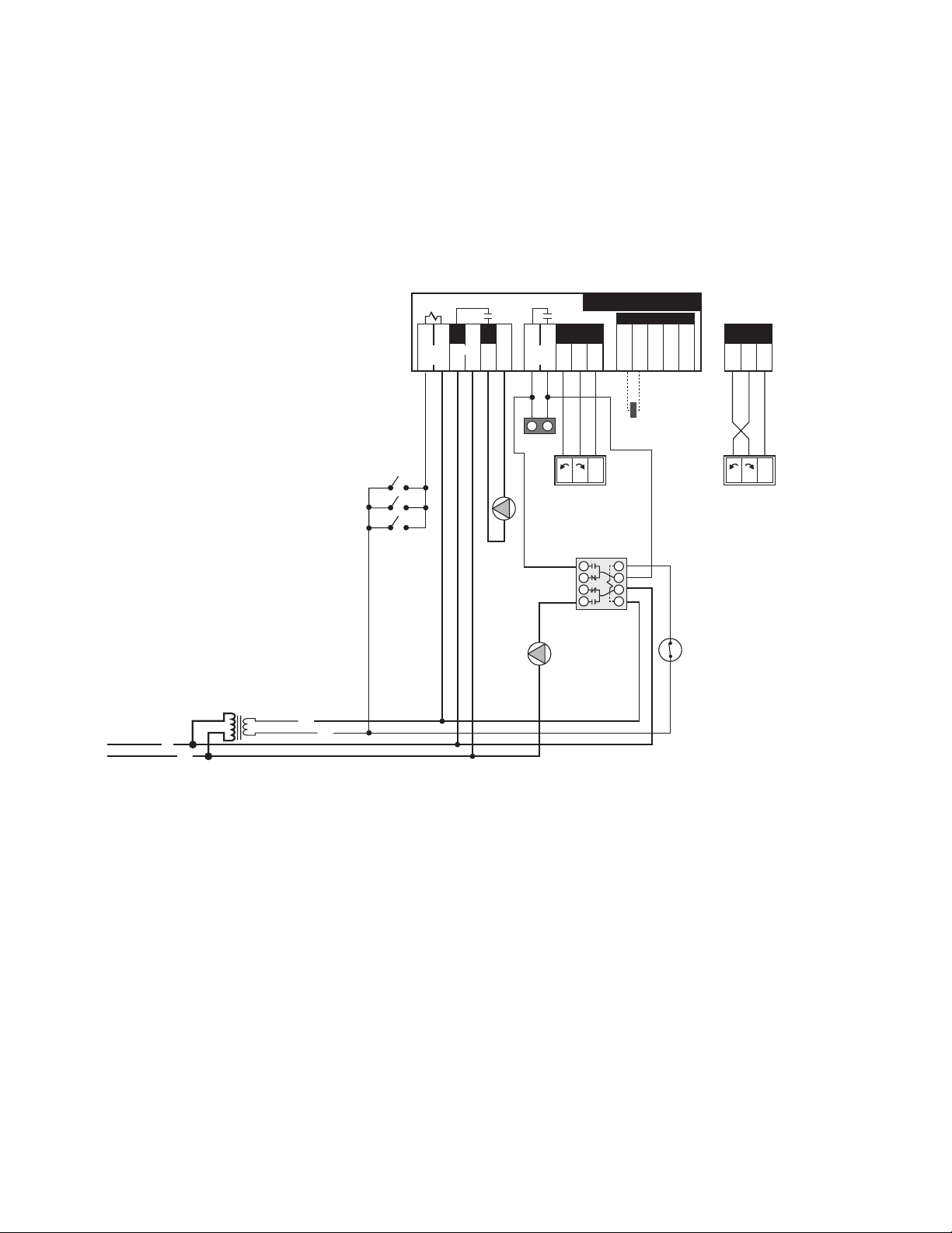
A8. 4-way RTC in Primary/Secondary - Heating and DHW using Indirect Water Heater on Primary Loop;
C
24 V (ac)
R
N
120 V (ac)
Class II
Transformer
L
S1
Do not apply power
10A
Boil
Ret
Com Mix OutCom
L
12 13 14 15 16
Boil
Pmp N
6
Burnham RTC
3 5
R
9
R
10
N
11
N
4
Power
10A
24 Volt Output
7 8
Boiler
Enable
1 2
Heat
Demand
P1
Boiler
C1
CW - Closed to System
C1
CW - Open to System
NL1 L1
Z1...Z3
R
9
R
10
N
11
24 Volt Output
NL1 L1
2
1
8
7
3
4
5
6
P2
A1
Breaks on
Temp. Rise
R1
without Outdoor Reset (Electrical)
A1 = Indirect Hot Water Aquastat
C1 = Mixing Valve Actuating Motor
P1 = Boiler Circulator
P2 = Indirect Circulator
R1 = Relay
S1 = Boiler Return Sensor
Z1...Z3 = Zone Valves, Zone Relays,
Thermostats or BMS Signal
NOTES:
1) Refer to the I&O to determine correct valve orientation and actuator wiring.
2) 120 VAC supplying the RTC should be separate from the burner/boiler circuit.
3) Heat demand can be any electrical signal consisting of 24 - 240 VAC.
4) Use isolation relays for circulators greater than 1/3 HP. Use motor starters for 3 phase circulators.
5) System Pump (P3) to be operated by zone relay or other installer supplied device.
This diagram is for reference only. The installer or designer is responsible for the proper selection and design
of the system.
41 of 60
Page 42

A9. 3-way Multiple Boiler RTC in Primary/Secondary - Heating and DHW using Indirect Water Heater on Primary Loop;
120 V (ac)
24 V (ac)
Class II
Transformer
264
Outdoor Sensor
(S4) 070
M
Z3
M
Z2
A1
P4
Boiler Return
Sensor
(S1) 071
P1
C1
M1
V1
V3
Boiler Return
Sensor
(S2) 071
P2
C2
M2
V2
V3
4D
Max
M
Z1
P3
R1
Indirect
DHW
Tank
RTC
RTC
S3
Using Sequencer with & without Outdoor Reset (Mechanical)
A1 = Indirect Hot Water Aquastat
C1,C2 = Diverting Valve Actuating Motor
M1,M2 = By-Pass Mix Point
P1,P2 = Boiler Circulator
P3 = System Pump (runs on call for heat)
P4 = Indirect Circulator
R1 = Relay
S1,S2 = Boiler Return Sensor
S3 = Mix Supply Senor 071
S4 = Outdoor Sensor 070
V1,V2 = 3-Way Diverting Valve
V3 = Ball Valve, Balancing Valve
Z1...Z3 = Zones
NOTES:
1) Install the boiler as indicated above for systems where return temperatures may be less than 135F and heating/DHW with an indirect water heater.
2) The Outdoor Sensor (S4) and the Mix Supply Sensor (S3) are required when the Outdoor Reset feature is selected. An appropriate
sequencer must also be selected. The mix sensor must be installed 10 pipe diameters downstream of the system pump, in the primary
loop. The mix sensor must be secured to the surface of the pipe using a wire tie or similar device.
3) The by-pass piping, diverting valve and boiler circulator must be sized using the sizing charts found in Appendix B.
4) A domestic hot water priority could be used provided the diversion from the heating system loop does not impact the system
heater’s performance.
5) Closely spaced tees must connect the branch to the larger header. The Tee centerlines must be no greater than 4 times the larger
header pipe diameter.
6) The diverting valves, V1 & V2, must be no greater than 11 linear feet of pipe from the Return Sensor, S1 & S2.
7) There shall be a MINIMUM of 4 linear feet of pipe between the By-pass Mix Point, M1 & M2, and the Return Sensor, S1 & S2.
8) The balancing valves in the boiler return lines, V3, may be necessary in low head by-pass loop applications.
9) The indirect heater aquastat (A1) is a normally closed switch. Circuit breaks on temperature rise.
10) Expansion tanks, air scoops and other components left out for clarity.
11) Observe all applicable plumbing and electrical codes.
This diagram is for reference only. The installer or designer is responsible for the proper selection and design of the
system.
42 of 60
Page 43

A9. 3-way Multiple Boiler RTC in Primary/Secondary - Heating and DHW using Indirect Water Heater on Primary Loop;
C
24 V (ac)
R
N
120 V (ac)
Class II
Transformer
L
S2
S3
Do not apply power
10A
Boil
Ret
Com Mix OutCom
L
12 13 14 15 16
Boil
Pmp N
6
Burnham RTC
3 5
R
9
R
10
N
11
N
4
Power
10A
24 Volt Output
7 8
Boiler
Enable
1 2
Heat
Demand
P2
Z1...Z3
R
9
R
10
N
11
24 Volt Output
Do not apply power
1
Com2Boil
Sup
3
Boil
Ret
4
Out5UnO
Sw
6
Boil
Dem
7
Com
Dem
8
Setp/
DHW
9
Power
N L
Prim
P1
12
C.A./
Alarm Pmp/Vlv
13 14
Relay
1
15
10 11
1
16
Relay
2172
18
Relay
3193
20
Relay
4214
22
DHW
23
264
5A 5A 5A 5A 5A 5A 5A
S1
S4
Do not apply power
10A
Boil
Ret
Com Mix OutCom
L
12 13 14 15 16
Boil
Pmp N
6
Burnham RTC
3 5
R
9
R
10
N
11
N
4
Power
10A
24 Volt Output
7 8
Boiler
Enable
1 2
Heat
Demand
P1
C1
CW - Open to System
R
9
R
10
N
11
24 Volt Output
NL1 L1
C1
CW - Closed to System
NL1 L1
P3
2
1
8
7
3
4
5
6
A1
Breaks on
Temp. Rise
P4
(Low) (High)
Boiler #2
(Low) (High)
Boiler #1
See 9,
10 & 11
at right
See 9,
10 & 11
at right
R1
Using Sequencer with & without Outdoor Reset (Electrical)
A1 = Indirect Hot Water Aquastat
C1,C2 = Mixing Valve Actuating Motor
P1,P2 = Boiler Circulator
P3 = System Pump (runs on
call for heat)
P4 = Indirect Circulator
R1 = Relay
S1,S2 = Boiler Return Sensor
S3 = Mix Supply Sensor 071
S4 = Outdoor Sensor 070
Z1...Z3 = Zone Valves, Zone Relays,
Thermostats or BMS Signal
NOTES:
1) Refer to the I&O to determine correct valve orientation and actuator wiring.
2) 120 VAC supplying the RTC should be separate from the burner/boiler circuit.
3) Heat demand can be any electrical signal consisting of 24 - 240 VAC.
4) Use isolation relays for circulators greater than 1/3 HP. Use motor starters for 3 phase circulators.
5) System Pump (P3) to be operated by zone relay or other installer supplied device.
This diagram is for reference only. The installer or designer is responsible for the proper selection and design
of the system.
43 of 60
Page 44

A10. 4-way Multiple Boiler RTC in Primary/Secondary - Heating and DHW using Indirect Water Heater on Primary Loop;
120 V (ac)
24 V (ac)
Class II
Transformer
264
Outdoor Sensor
(S4) 070
M
Z3
M
Z2
A1
P4
Boiler Return
P1
C1
M1
V1
V3
Boiler Return
P2
C2
M2
V2
V3
4D
Max
M
Z1
P3
R1
Indirect
DHW
Tank
RTC
RTC
S3
M
M
Using Sequencer with & without Outdoor Reset (Mechanical)
A1 = Indirect Hot Water Aquastat
C1,C2 = Diverting Valve Actuating Motor
M1,M2 = By-Pass Mix Point
P1,P2 = Boiler Circulator
P3 = System Pump (runs on call for heat)
P4 = Indirect Circulator
R1 = Relay
S1,S2 = Boiler Return Sensor
S3 = Mix Supply Senor 071
S4 = Outdoor Sensor 070
V1,V2 = 3-Way Diverting Valve
V3 = Ball Valve, Balancing Valve
Z1...Z3 = Zones
NOTES:
1) Install the boiler as indicated above for systems where return temperatures may be less than 135F and heating/DHW with an indirect water heater.
2) The Outdoor Sensor (S4) and the Mix Supply Sensor (S3) are required when the Outdoor Reset feature is selected. An appropriate
sequencer must also be selected. The mix sensor must be installed 10 pipe diameters downstream of the system pump, in the primary
loop. The mix sensor must be secured to the surface of the pipe using a wire tie or similar device.
3) The by-pass piping, diverting valve and boiler circulator must be sized using the sizing charts found in Appendix B.
4) A domestic hot water priority could be used provided the diversion from the heating system loop does not impact the system
heater’s performance.
5) Closely spaced tees must connect the branch to the larger header. The Tee centerlines must be no greater than 4 times the larger
header pipe diameter.
6) The diverting valves, V1 & V2, must be no greater than 11 linear feet of pipe from the Return Sensor, S1 & S2.
7) There shall be a MINIMUM of 4 linear feet of pipe between the By-pass Mix Point, M1 & M2, and the Return Sensor, S1 & S2.
8) The balancing valves in the boiler return lines, V3, may be necessary in low head by-pass loop applications.
9) The indirect heater aquastat (A1) is a normally closed switch. Circuit breaks on temperature rise.
10) Expansion tanks, air scoops and other components left out for clarity.
11) Observe all applicable plumbing and electrical codes.
This diagram is for reference only. The installer or designer is responsible for the proper selection and design of the
system.
44 of 60
Page 45

A10. 4-way Multiple Boiler RTC in Primary/Secondary - Heating and DHW using Indirect Water Heater on Primary Loop;
C
24 V (ac)
R
N
120 V (ac)
Class II
Transformer
L
S2
S3
Do not apply power
10A
Boil
Ret
Com Mix OutCom
L
12 13 14 15 16
Boil
Pmp N
6
Burnham RTC
3 5
R
9
R
10
N
11
N
4
Power
10A
24 Volt Output
7 8
Boiler
Enable
1 2
Heat
Demand
P2
Z1...Z3
R
9
R
10
N
11
24 Volt Output
Do not apply power
1
Com2Boil
Sup
3
Boil
Ret
4
Out5UnO
Sw
6
Boil
Dem
7
Com
Dem
8
Setp/
DHW
9
Power
N L
Prim
P1
12
C.A./
Alarm Pmp/Vlv
13 14
Relay
1
15
10 11
1
16
Relay
2172
18
Relay
3193
20
Relay
4214
22
DHW
23
264
5A 5A 5A 5A 5A 5A 5A
S1
S4
Do not apply power
10A
Boil
Ret
Com Mix OutCom
L
12 13 14 15 16
Boil
Pmp N
6
Burnham RTC
3 5
R
9
R
10
N
11
N
4
Power
10A
24 Volt Output
7 8
Boiler
Enable
1 2
Heat
Demand
P1
C1
CW - Open to System
R
9
R
10
N
11
24 Volt Output
NL1 L1
C1
CW - Closed to System
NL1 L1
P3
2
1
8
7
3
4
5
6
A1
Breaks on
Temp. Rise
P4
(Low) (High)
Boiler #2
(Low) (High)
Boiler #1
See 9,
10 & 11
at right
See 9,
10 & 11
at right
R1
Using Sequencer with & without Outdoor Reset (Electrical)
A1 = Indirect Hot Water Aquastat
C1,C2 = Mixing Valve Actuating Motor
P1,P2 = Boiler Circulator
P3 = System Pump (runs on
call for heat)
P4 = Indirect Circulator
R1 = Relay
S1,S2 = Boiler Return Sensor
S3 = Mix Supply Sensor 071
S4 = Outdoor Sensor 070
Z1...Z3 = Zone Valves, Zone Relays,
Thermostats or BMS Signal
NOTES:
1) Refer to the I&O to determine correct valve orientation and actuator wiring.
2) 120 VAC supplying the RTC should be separate from the burner/boiler circuit.
3) Heat demand can be any electrical signal consisting of 24 - 240 VAC.
4) Use isolation relays for circulators greater than 1/3 HP. Use motor starters for 3 phase circulators.
5) System Pump (P3) to be operated by zone relay or other installer supplied device.
This diagram is for reference only. The installer or designer is responsible for the proper selection and design
of the system.
45 of 60
Page 46
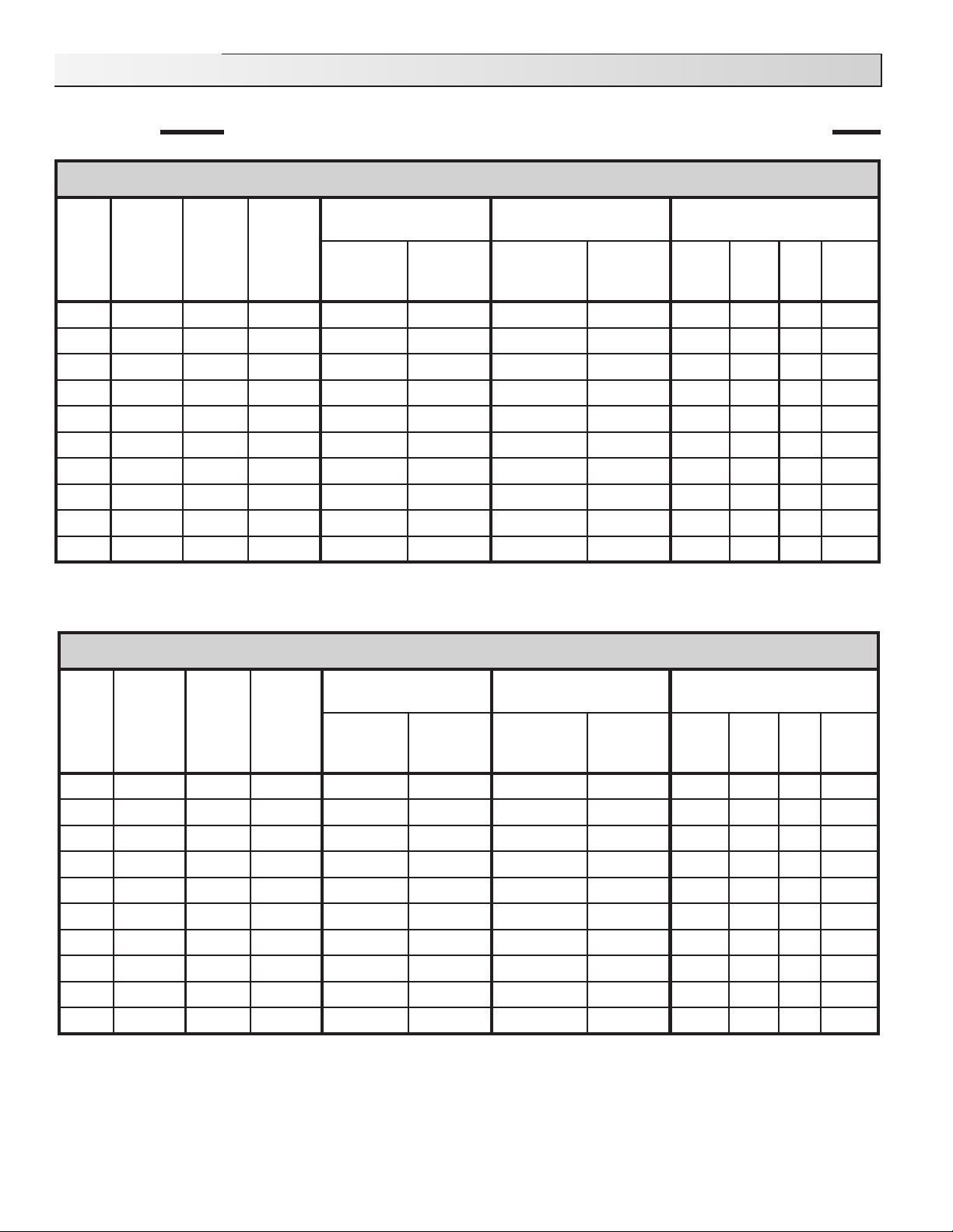
Appendix B: Boiler Circulator and Diverting Valve Selection Charts
)laitnereffiDF∞04(OCAT-noitceleSrotalucriCrelioB9V
EZIS
RBI
SSORG
TUPTUO
)HBM(
LATOT
MPG
epiP
eziS
noitalucriceRrelioB
yaW-3
noitalucriceRrelioB
yaW-4
pmuPgnitalucriCOCAT
evlaV
eziS
evlaV
traP
rebmuN
evlaV
eziS
evlaV
traP
rebmuN
ledoM
.oN
"pmI PH MPR
A309V 643 71 "5.1 TPN"0.1 31094108 TPN"0.1 61099108 700 A/N 52/1 0523
A409V 384 42 "5.1 TPN"52.1 65306108 TPN"52.1 71094108 0100 A/N 8/1 0523
A509V 646 23 "5.1 TPN"5.1 75306108 TPN"5.1 42094108 C111 A/N 8/1 5271
A609V 808 04 "5.1 TPN"5.1 75306108 TPN"5.1 42094108 C121 A/N 4/1 5271
A709V 959 84 "0.2 TPN"0.2 85306108 TPN"0.2 52094108 C021 A/N 6/1 5271
A809V 0111 65 "0.2 TPN"0.2 85306108 TPN"0.2 52094108 1161 "1.4 4/1 0571
A909V 2431 76 "0.2 TPN"0.2 85306108 TPN"0.2 52094108 C221 A/N 4/1 5271
A019V 8251 67 "5.2 egnalF"5.2* 95306108 egnalF"5.2* 66306108 C121 A/N 4/1 5271
A119V 4171 68 "5.2 egnalF"5.2* 95306108 egnalF"5.2* 66306108 131 A/N 3/1 5271
A219V 0091 59 "5.2 egnalF"5.2* 95306108 egnalF"5.2* 66306108 5361 "5.4 2/1** 0571
.evlavyaw-4"Ω2054FledoMroevlavyaw-3"Ω205-561FledoM*
.rewoPesahP3rofretratSrotoMesU.rewoPesahPelgniSrofyaleRlanoitiddAesU**
Appendix B1
V9A Boiler Circulator and Diverting Valve Selection Chart, 20°F & 40°F DT, TACO
46 of 60
Page 47

)laitnereffiDF∞02(sofdnurG-noitceleSrotalucriCrelioB9V
EZIS
RBI
SSORG
TUPTUO
)HBM(
LATOT
MPG
epiP
eziS
noitalucriceRrelioB
yaW-3
noitalucriceRrelioB
yaW-4
pmuPgnitalucriCsofdnurG
evlaV
eziS
evlaV
traP
rebmuN
evlaV
eziS
evlaV
traP
rebmuN
.oNledoM "pmI PH MPR
A309V 643 53 "0.2 TPN"5.1 75306108 TPN"5.1 42094108 4/04-23SPU 93.3 3/1 7661
A409V 384 84 "0.2 TPN"5.1 75306108 TPN"5.1 42094108 2/08-23SPU 25.2 2/1** 0043
A509V 646 56 "0.2 TPN"2 85306108 TPN"2 52094108 4/08-04SPU 68.4 2/1** 7851
A609V 808 18 "5.2 egnalF"5.2* 95306108 egnalF"5.2* 66306108 4/08-04SPU 68.4 2/1** 7851
A709V 959 69 "5.2 egnalF"5.2* 95306108 egnalF"5.2* 66306108 4/08-05SPU 79.4 4/3** 7061
A809V 0111 111 "5.2 egnalF"5.2* 95306108 egnalF"5.2* 66306108 2/08-05SPU 19.2 4/3** 6243
A909V 2431 431 "0.3 egnalF"5.2 06306108 egnalF"5.2 62094108 4/04-08PT 37.3 2/1** 0571
A019V 8251 351 "0.3 egnalF"5.2 06306108 egnalF"5.2 62094108 4/04-001PT 01.4 1** 0571
A119V 4171 171 "0.3 egnalF"5.2 06306108 egnalF"5.2 62094108 4/04-001PT 01.4 1** 0571
A219V 0091 091 "0.4 egnalF"0.3 16306108 egnalF"0.3 84306108 4/08-001PT 42.5 2** 0571
.evlavyaw-4"Ω2054FledoMroevlavyaw-3"Ω205-561FledoM*
.rewoPesahP3rofretratSrotoMesU.rewoPesahPelgniSrofyaleRlanoitiddAesU**
Appendix B2
)laitnereffiDF∞04(sofdnurG-noitceleSrotalucriCrelioB9V
EZIS
RBI
SSORG
TUPTUO
)HBM(
LATOT
MPG
epiP
eziS
noitalucriceRrelioB
yaW-3
noitalucriceRrelioB
yaW-4
pmuPgnitalucriCsofdnurG
evlaV
eziS
evlaV
traP
rebmuN
evlaV
eziS
evlaV
traP
rebmuN
.oNledoM "pmI PH MPR
A309V 643 71 "5.1 TPN"0.1 31094108 TPN"0.1 61099108 4/04-23SPU 93.3 3/1 4951
A409V 384 42 "5.1 TPN"52.1 65306108 TPN"52.1 71094108 4/04-23SPU 93.3 3/1 7661
A509V 646 23 "5.1 TPN"5.1 75306108 TPN"5.1 42094108 4/04-23SPU 93.3 3/1 2171
A609V 808 04 "5.1 TPN"5.1 75306108 TPN"5.1 42094108 2/08-23SPU 25.2 2/1** 0043
A709V 959 84 "0.2 TPN"0.2 85306108 TPN"0.2 52094108 2/08-23SPU 25.2 2/1** 0043
A809V 0111 65 "0.2 TPN"0.2 85306108 TPN"0.2 52094108 4/08-04SPU 68.4 2/1** 0541
A909V 2431 76 "0.2 TPN"0.2 85306108 TPN"0.2 52094108 4/08-04SPU 68.4 2/1** 7851
A019V 8251 67 "5.2 egnalF"5.2* 95306108 egnalF"5.2* 66306108 4/08-04SPU 68.4 2/1** 7851
A119V 4171 68 "5.2 egnalF"5.2* 95306108 egnalF"5.2* 66306108 4/08-04SPU 68.4 2/1** 8861
A219V 0091 59 "5.2 egnalF"5.2* 95306108 egnalF"5.2* 66306108 4/08-05SPU 79.4 4/3** 7061
.evlavyaw-4"Ω2054FledoMroevlavyaw-3"Ω205-561FledoM*
.rewoPesahP3rofretratSrotoMesU.rewoPesahPelgniSrofyaleRlanoitiddAesU**
V9A Boiler Circulator and Diverting Valve Selection Chart, 20°F & 40°F DT, Grundfos
47 of 60
Page 48

)laitnereffiDF∞02(ttessoGdnalleB-noitceleSrotalucriCrelioB9V
EZIS
RBI
SSORG
TUPTUO
)HBM(
LATOT
MPG
epiP
eziS
noitalucriceRrelioB
yaW-3
noitalucriceRrelioB
yaW-4
pmuPgnitalucriCttessoGdnalleB
evlaV
eziS
evlaV
traP
rebmuN
evlaV
eziS
evlaV
traP
rebmuN
.oNledoM "pmI PH MPR
A309V 643 53 "0.2 TPN"5.1 75306108 TPN"5.1 42094108 "5.1-63-LP .dtS 6/1 0033
A409V 384 84 "0.2 TPN"5.1 75306108 TPN"5.1 42094108 "2-57-LP .dtS 6/1 0043
A509V 646 56 "0.2 TPN"2 85306108 TPN"2 52094108 "2-031-LP .dtS 5/2** 0023
A609V 808 18 "5.2 egnalF"5.2* 95306108 egnalF"5.2* 66306108 "2-031-LP .dtS 5/2** 0023
A709V 959 69 "5.2 egnalF"5.2* 95306108 egnalF"5.2* 66306108 "2-031-LP .dtS 5/2** 0023
A809V 0111 111 "5.2 egnalF"5.2* 95306108 egnalF"5.2* 66306108 "2-016.doM,06.reS "4 2/1** 0571
A909V 2431 431 "0.3 egnalF"5.2 06306108 egnalF"5.2 62094108 "2-016.doM,06.reS "4 2/1** 0571
A019V 8251 351 "0.3 egnalF"5.2 06306108 egnalF"5.2 62094108 B7x3x3.doM,08.reS "5 1** 0571
A119V 4171 171 "0.3 egnalF"5.2 06306108 egnalF"5.2 62094108 B7x3x3.doM,08.reS "5 1** 0571
A219V 0091 091 "0.4 egnalF"0.3 16306108 egnalF"0.3 84306108 B7x3x3.doM,08.reS "5 1** 0571
* .evlavyaw-4"Ω2054FledoMroevlavyaw-3"Ω205-561FledoM
Appendix B3
)laitnereffiDF∞04(ttessoGdnalleB-noitceleSrotalucriCrelioB9V
EZIS
RBI
SSORG
TUPTUO
)HBM(
LATOT
MPG
epiP
eziS
noitalucriceRrelioB
yaW-3
noitalucriceRrelioB
yaW-4
pmuPgnitalucriCttessoGdnalleB
evlaV
eziS
evlaV
traP
rebmuN
evlaV
eziS
evlaV
traP
rebmuN
.oNledoM "pmI PH MPR
A309V 643 71 "5.1 TPN"0.1 31094108 TPN"0.1 61099108 33-FRN .dtS 51/1 0592
A409V 384 42 "5.1 TPN"52.1 65306108 TPN"52.1 71094108 63-LP .dtS 6/1 0033
A509V 646 23 "5.1 TPN"5.1 75306108 TPN"5.1 42094108 63-LP .dtS 6/1 0033
A609V 808 04 "5.1 TPN"5.1 75306108 TPN"5.1 42094108 54-LP .dtS 6/1 0033
A709V 959 84 "0.2 TPN"0.2 85306108 TPN"0.2 52094108 57-LP .dtS 6/1 0043
A809V 0111 65 "0.2 TPN"0.2 85306108 TPN"0.2 52094108 57-LP .dtS 6/1 0043
A909V 2431 76 "0.2 TPN"0.2 85306108 TPN"0.2 52094108 "2-031-LP .dtS 5/2** 0023
A019V 8251 67 "5.2 egnalF"5.2* 95306108 egnalF"5.2* 66306108 "2-031-LP .dtS 5/2** 0023
A119V 4171 68 "5.2 egnalF"5.2* 95306108 egnalF"5.2* 66306108 "2-031-LP .dtS 5/2** 0023
A219V 0091 59 "5.2 egnalF"5.2* 95306108 egnalF"5.2* 66306108 "2-031-LP .dtS 5/2** 0023
.evlavyaw-4"Ω2054FledoMroevlavyaw-3"Ω205-561FledoM*
.rewoPesahP3rofretratSrotoMesU.rewoPesahPelgniSrofyaleRlanoitiddAesU**
V9A Boiler Circulator and Diverting Valve Selection Chart, 20°F & 40°F DT, Bell and Gossett
48 of 60
Page 49

)laitnereffiDF∞02(gnortsmrA-noitceleSrotalucriCrelioB9V
EZIS
RBI
SSORG
TUPTUO
)HBM(
LATOT
MPG
epiP
eziS
noitalucriceRrelioB
yaW-3
noitalucriceRrelioB
yaW-4
pmuPgnitalucriCgnortsmrA
evlaV
eziS
evlaV
traP
rebmuN
evlaV
eziS
evlaV
traP
rebmuN
.oNledoM "pmI PH MPR
A309V 643 53 "0.2 TPN"5.1 75306108 TPN"5.1 42094108 01-E lluF 6/1 ---
A409V 384 84 "0.2 TPN"5.1 75306108 TPN"5.1 42094108 54-S 578.3 4/1 0081
A509V 646 56 "0.2 TPN"2 85306108 TPN"2 52094108 64-S 52.4 3/1 0021
A609V 808 18 "5.2 egnalF"5.2* 95306108 egnalF"5.2* 66306108 64-S 52.4 3/1 0021
A709V 959 69 "5.2 egnalF"5.2* 95306108 egnalF"5.2* 66306108 6x3x30834 40.5 3/1 0021
A809V 0111 111 "5.2 egnalF"5.2* 95306108 egnalF"5.2* 66306108 6x3x30834 765.5 2/1** 0021
A909V 2431 431 "0.3 egnalF"5.2 06306108 egnalF"5.2 62094108 6x3x30834 32.5 3/1 0021
A019V 8251 351 "0.3 egnalF"5.2 06306108 egnalF"5.2 62094108 6x4x40834 179.4 2/1** 0021
A119V 4171 171 "0.3 egnalF"5.2 06306108 egnalF"5.2 62094108 6x4x40834 173.5 2/1** 0021
A219V 0091 091 "0.4 egnalF"0.3 16306108 egnalF"0.3 84306108 6x4x40834 198.4 2/1** 0021
* .evlavyaw-4"Ω2054FledoMroevlavyaw-3"Ω205-561FledoM
Appendix B4
)laitnereffiDF∞04(gnortsmrA-noitceleSrotalucriCrelioB9V
EZIS
RBI
SSORG
TUPTUO
)HBM(
LATOT
MPG
epiP
eziS
noitalucriceRrelioB
yaW-3
noitalucriceRrelioB
yaW-4
pmuPgnitalucriCgnortsmrA
evlaV
eziS
evlaV
traP
rebmuN
evlaV
eziS
evlaV
traP
rebmuN
.oNledoM "pmI PH MPR
A309V 643 71 "5.1 TPN"0.1 31094108 TPN"0.1 61099108 52-S 57.2 6/1 0081
A409V 384 42 "5.1 TPN"52.1 65306108 TPN"52.1 71094108 52-S 57.2 21/1 0081
A509V 646 23 "5.1 TPN"5.1 75306108 TPN"5.1 42094108 8-E lluF 6/1 0063
A609V 808 04 "5.1 TPN"5.1 75306108 TPN"5.1 42094108 53-S 573.3 6/1 0081
A709V 959 84 "0.2 TPN"0.2 85306108 TPN"0.2 52094108 64-S 573.3 4/1 0081
A809V 0111 65 "0.2 TPN"0.2 85306108 TPN"0.2 52094108 54-S 578.3 4/1 0081
A909V 2431 76 "0.2 TPN"0.2 85306108 TPN"0.2 52094108 64-S 578.3 3/1 0081
A019V 8251 67 "5.2 egnalF"5.2* 95306108 egnalF"5.2* 66306108 6x3x30834 899.4 3/1 0021
A119V 4171 68 "5.2 egnalF"5.2* 95306108 egnalF"5.2* 66306108 6x3x30834 776.4 3/1 0021
A219V 0091 59 "5.2 egnalF"5.2* 95306108 egnalF"5.2* 66306108 6x3x30834 910.5 3/1 0021
.evlavyaw-4"Ω2054FledoMroevlavyaw-3"Ω205-561FledoM*
V9A Boiler Circulator and Diverting Valve Selection Chart, 20°F & 40°F DT, Armstrong
49 of 60
Page 50

)laitnereffiDF∞02(OCAT-noitceleSrotalucriCrelioB11V
EZIS
RBI
SSORG
TUPTUO
)HBM(
LATOT
MPG
epiP
eziS
noitalucriceRrelioB
yaW-3
noitalucriceRrelioB
yaW-4
pmuPgnitalucriCOCAT
evlaV
eziS
evlaV
traP
rebmuN
evlaV
eziS
evlaV
traP
rebmuN
ledoM
.oN
"pmI PH MPR
4011V 766 76 "5.2 TPN"0.2 85306108 TPN"0.2 52094108 6051VK "7.4 1** 0571
5011V 758 68 "5.2 egnalF"5.2* 95306108 egnalF"5.2* 66306108 6002VK "5.4 1** 0571
6011V 9601 701 "5.2 egnalF"5.2* 95306108 egnalF"5.2* 66306108 5361 "8.4 4/3** 0571
7011V 1821 821 "0.3 egnalF"5.2 06306108 egnalF"5.2 62094108 6003VK "4.4 1** 0571
8011V 7151 251 "0.3 egnalF"5.2 06306108 egnalF"5.2 62094108 6003VK "0.5 1** 0571
9011V 9271 371 "0.4 egnalF"5.2 06306108 egnalF"5.2 62094108 7003VK "5.5 1** 0511
0111V 1491 491 "0.4 egnalF"0.3 16306108 egnalF"0.3 84306108 7003VK "5.5 1** 0511
1111V 4512 512 "0.4 egnalF"0.3 16306108 egnalF"0.3 84306108 7003VK "0.6 1** 0511
2111V 4332 332 "0.4 egnalF"0.3 16306108 egnalF"0.3 84306108 7003VK "2.6 1** 0511
3111V 3052 052 "0.4 egnalF"0.3 16306108 egnalF"0.3 84306108 7004VK "6.5 1** 0611
4111V 0372 372 "0.4 egnalF"0.4 26306108 egnalF"0.4 46306108 7004VK "8.5 1** 0611
5111V 7592 692 "0.4 egnalF"0.4 26306108 egnalF"0.4 46306108 7005VK "7.5 1** 0611
6111V 6213 313 "0.5 egnalF"0.4 26306108 egnalF"0.4 46306108 7005VK "5.5 1** 0511
7111V 3533 533 "0.5 egnalF"0.4 26306108 egnalF"0.4 46306108 7005VK "8.5 1** 0611
8111V 0853 853 "0.5 egnalF"0.4 26306108 egnalF"0.4 46306108 7005VK "9.5 Ω1** 0611
9111V 9373 473 "0.5 egnalF"0.5 36306108 egnalF"0.5 56306108 9003IC "3.6 Ω1** 0611
0211V 7593 693 "0.5 egnalF"0.5 36306108 egnalF"0.5 56306108 9003IC "5.6 Ω1** 0611
1211V 4714 714 "0.5 egnalF"0.5 36306108 egnalF"0.5 56306108 7004IC "6.6 Ω1** 0611
2211V 4334 334 "0.5 egnalF"0.5 36306108 egnalF"0.5 56306108 7004IC "7.6 2** 0611
3211V 1554 554 "0.5 egnalF"0.5 36306108 egnalF"0.5 56306108 7004IC "9.6 2** 0611
.evlavyaw-4"Ω2054FledoMroevlavyaw-3"Ω205-561FledoM*
.rewoPesahP3rofretratSrotoMesU.rewoPesahPelgniSrofyaleRlanoitiddAesU**
Appendix B5
V11 Boiler Circulator and Diverting Valve Selection Chart, 20°F & 40°F DT, TACO
50 of 60
Page 51

)laitnereffiDF∞04(OCAT-noitceleSrotalucriCrelioB11V
EZIS
RBI
SSORG
TUPTUO
)HBM(
LATOT
MPG
epiP
eziS
noitalucriceRrelioB
yaW-3
noitalucriceRrelioB
yaW-4
pmuPgnitalucriCOCAT
evlaV
eziS
evlaV
traP
rebmuN
evlaV
eziS
evlaV
traP
rebmuN
ledoM
.oN
"pmI PH MPR
4011V 766 33 "0.2 TPN"5.1 75306108 TPN"5.1 42094108 111 A/N 8/1 5271
5011V 758 34 "0.2 TPN"5.1 75306108 TPN"5.1 42094108 021 A/N 6/1 5271
6011V 9601 35 "0.2 TPN"0.2 85306108 TPN"0.2 52094108 021 A/N 6/1 5271
7011V 1821 46 "0.2 TPN"0.2 85306108 TPN"0.2 52094108 121 A/N 4/1** 5271
8011V 7151 67 "0.2 TPN"0.2 85306108 TPN"0.2 52094108 131 A/N 3/1 5271
9011V 9271 68 "5.2 egnalF"5.2* 95306108 egnalF"5.2* 66306108 121 A/N 4/1** 5271
0111V 1491 79 "5.2 egnalF"5.2* 95306108 egnalF"5.2* 66306108 5361 "5.4 2/1** 0571
1111V 4512 801 "5.2 egnalF"5.2* 95306108 egnalF"5.2* 66306108 5361 "8.4 4/3** 0571
2111V 4332 711 "0.3 egnalF"5.2 06306108 egnalF"5.2 62094108 5361 "9.4 4/3** 0571
3111V 3052 521 "0.3 egnalF"5.2 06306108 egnalF"5.2 62094108 5361 "2.5 4/3** 0571
4111V 0372 731 "0.3 egnalF"5.2 06306108 egnalF"5.2 62094108 5361 "5.5 1** 0571
5111V 7592 841 "0.3 egnalF"5.2 06306108 egnalF"5.2 62094108 6003VK "9.4 1** 0571
6111V 6213 651 "0.3 egnalF"5.2 06306108 egnalF"5.2 62094108 6003VK "1.5 1** 0571
7111V 3533 861 "0.3 egnalF"5.2 06306108 egnalF"5.2 62094108 7003VK "9.5 1** 0611
8111V 0853 971 "0.4 egnalF"0.3 16306108 egnalF"0.3 84306108 7003VK "6.5 1** 0611
9111V 9373 781 "0.4 egnalF"0.3 16306108 egnalF"0.3 84306108 7003VK "6.5 1** 0611
0211V 7593 891 "0.4 egnalF"0.3 16306108 egnalF"0.3 84306108 7003VK "7.5 1** 0611
1211V 4714 902 "0.4 egnalF"0.3 16306108 egnalF"0.3 84306108 7003VK "9.5 1** 0611
2211V 4334 712 "0.4 egnalF"0.3 16306108 egnalF"0.3 84306108 7003VK "1.6 1** 0611
3211V 1554 822 "0.4 egnalF"0.3 16306108 egnalF"0.3 84306108 7003VK "3.6 1** 0611
.evlavyaw-4"Ω2054FledoMroevlavyaw-3"Ω205-561FledoM*
.rewoPesahP3rofretratSrotoMesU.rewoPesahPelgniSrofyaleRlanoitiddAesU**
51 of 60
Page 52

)laitnereffiDF∞02(sofdnurG-noitceleSrotalucriCrelioB11V
EZIS
RBI
SSORG
TUPTUO
)HBM(
LATOT
MPG
eziSepiP
noitalucriceRrelioB
yaW-3
noitalucriceRrelioB
yaW-4
pmuPgnitalucriCsofdnurG
evlaV
eziS
evlaV
traP
rebmuN
evlaV
eziS
evlaV
traP
rebmuN
.oNledoM "pmI PH MPR
4011V 766 76 "5.2 TPN"0.2 85306108 TPN"0.2 52094108 4/08-04SPU 68.4 2/1** 7851
5011V 758 68 "5.2 egnalF"5.2* 95306108 egnalF"5.2* 66306108 4/08-04SPU 68.4 2/1** 8861
6011V 9601 701 "5.2 egnalF"5.2* 95306108 egnalF"5.2* 66306108 4/08-05SPU 79.4 4/3** 4961
7011V 1821 821 "0.3 egnalF"5.2 06306108 egnalF"5.2 62094108 2/08-05SPU 19.2 4/3** 6243
8011V 7151 251 "0.3 egnalF"5.2 06306108 egnalF"5.2 62094108 4/04-001PT 1.4 1** 0571
9011V 9271 371 "0.4 egnalF"5.2 06306108 egnalF"5.2 62094108 4/04-001PT 1.4 1** 0571
0111V 1491 491 "0.4 egnalF"0.3 16306108 egnalF"0.3 84306108 --- --- --- ---
1111V 4512 512 "0.4 egnalF"0.3 16306108 egnalF"0.3 84306108 --- --- --- ---
2111V 4332 332 "0.4 egnalF"0.3 16306108 egnalF"0.3 84306108 --- --- --- ---
3111V 3052 052 "0.4 egnalF"0.3 16306108 egnalF"0.3 84306108 2/061-08SPU 65.3 3** 3153
4111V 0372 372 "0.4 egnalF"0.4 26306108 egnalF"0.4 46306108 --- --- --- ---
5111V 7592 692 "0.4 egnalF"0.4 26306108 egnalF"0.4 46306108 --- --- --- ---
6111V 6213 313 "0.5 egnalF"0.4 26306108 egnalF"0.4 46306108 --- --- --- ---
7111V 3533 533 "0.5 egnalF"0.4 26306108 egnalF"0.4 46306108 --- --- --- ---
8111V 0853 853 "0.5 egnalF"0.4 26306108 egnalF"0.4 46306108 --- --- --- ---
9111V 9373 473 "0.5 egnalF"0.5 36306108 egnalF"0.5 56306108 --- --- --- ---
0211V 7593 693 "0.5 egnalF"0.5 36306108 egnalF"0.5 56306108 --- --- --- ---
1211V 4714 714 "0.5 egnalF"0.5 36306108 egnalF"0.5 56306108 --- --- --- ---
2211V 4334 334 "0.5 egnalF"0.5 36306108 egnalF"0.5 56306108 --- --- --- ---
3211V 1554 554 "0.5 egnalF"0.5 36306108 egnalF"0.5 56306108 --- --- --- ---
.evlavyaw-4"Ω2054FledoMroevlavyaw-3"Ω205-561FledoM*
.rewoPesahP3rofretratSrotoMesU.rewoPesahPelgniSrofyaleRlanoitiddAesU**
Appendix B6
V11 Boiler Circulator and Diverting Valve Selection Chart, 20°F & 40°F DT, Grundfos
52 of 60
Page 53

)laitnereffiDF∞04(sofdnurG-noitceleSrotalucriCrelioB11V
EZIS
RBI
SSORG
TUPTUO
)HBM(
LATOT
MPG
epiP
eziS
noitalucriceRrelioB
yaW-3
noitalucriceRrelioB
yaW-4
pmuPgnitalucriCsofdnurG
evlaV
eziS
evlaV
traP
rebmuN
evlaV
eziS
evlaV
traP
rebmuN
.oNledoM "pmI PH MPR
4011V 766 33 "0.2 TPN"5.1 75306108 TPN"5.1 42094108 4/04-23SPU 93.3 3/1 7661
5011V 758 34 "0.2 TPN"5.1 75306108 TPN"5.1 42094108 2/08-23SPU 25.2 2/1** 1823
6011V 9601 35 "0.2 TPN"0.2 85306108 TPN"0.2 52094108 2/08-23SPU 25.2 2/1** 0043
7011V 1821 46 "0.2 TPN"0.2 85306108 TPN"0.2 52094108 4/08-04SPU 68.4 2/1** 7851
8011V 7151 67 "0.2 TPN"0.2 85306108 TPN"0.2 52094108 4/08-04SPU 68.4 2/1** 8861
9011V 9271 68 "5.2 egnalF"5.2* 95306108 egnalF"5.2* 66306108 4/08-04SPU 68.4 2/1** 8861
0111V 1491 79 "5.2 egnalF"5.2* 95306108 egnalF"5.2* 66306108 4/08-05SPU 79.4 4/3** 4961
1111V 4512 801 "5.2 egnalF"5.2* 95306108 egnalF"5.2* 66306108 4/08-05SPU 79.4 4/3** 4961
2111V 4332 711 "0.3 egnalF"5.2 06306108 egnalF"5.2 62094108 4/08-05SPU 79.4 4/3** 7061
3111V 3052 521 "0.3 egnalF"5.2 06306108 egnalF"5.2 62094108 4/08-05SPU 79.4 4/3** 4961
4111V 0372 731 "0.3 egnalF"5.2 06306108 egnalF"5.2 62094108 4/08-05SPU 30.5 2/1** 4961
5111V 7592 841 "0.3 egnalF"5.2 06306108 egnalF"5.2 62094108 2/061-05SPU 1.4 1** 5933
6111V 6213 651 "0.3 egnalF"5.2 06306108 egnalF"5.2 62094108 2/061-05SPU 75.3 3** 5933
7111V 3533 861 "0.3 egnalF"5.2 06306108 egnalF"5.2 62094108 2/061-05SPU 75.3 3** 3153
8111V 0853 971 "0.4 egnalF"0.3 16306108 egnalF"0.3 84306108 4/04-001SPU 75.3 3** 2171
9111V 9373 781 "0.4 egnalF"0.3 16306108 egnalF"0.3 84306108 4/04-001SPU 75.3 3** 2171
0211V 7593 891 "0.4 egnalF"0.3 16306108 egnalF"0.3 84306108 4/04-001SPU 75.3 3** 2171
1211V 4714 902 "0.4 egnalF"0.3 16306108 egnalF"0.3 84306108 2/061-08SPU 75.3 3** 3153
2211V 4334 712 "0.4 egnalF"0.3 16306108 egnalF"0.3 84306108 2/061-08SPU 75.3 3** 3153
3211V 1554 822 "0.4 egnalF"0.3 16306108 egnalF"0.3 84306108 2/061-08SPU 75.3 3** 3153
.evlavyaw-4"Ω2054FledoMroevlavyaw-3"Ω205-561FledoM*
.rewoPesahP3rofretratSrotoMesU.rewoPesahPelgniSrofyaleRlanoitiddAesU**
53 of 60
Page 54

)laitnereffiDF∞02(ttessoGdnalleB-noitceleSrotalucriCrelioB11V
EZIS
RBI
SSORG
TUPTUO
)HBM(
LATOT
MPG
epiP
eziS
noitalucriceRrelioB
yaW-3
noitalucriceRrelioB
yaW-4
pmuPgnitalucriCttessoGdnalleB
evlaV
eziS
evlaV
traP
rebmuN
evlaV
eziS
evlaV
traP
rebmuN
.oNledoM "pmI PH MPR
4011V 766 76 "5.2 TPN"0.2 85306108 TPN"0.2 52094108 "2-031-LP .dtS 5/2** 0023
5011V 758 68 "5.2 egnalF"5.2* 95306108 egnalF"5.2* 66306108 "2-031-LP .dtS 5/2** 0023
6011V 9601 701 "5.2 egnalF"5.2* 95306108 egnalF"5.2* 66306108 "2-016.doM,06.reS "4 2/1** 0571
7011V 1821 821 "0.3 egnalF"5.2 06306108 egnalF"5.2 62094108 "2-016.doM,06.reS "4 2/1** 0571
8011V 7151 251 "0.3 egnalF"5.2 06306108 egnalF"5.2 62094108 B7x3x3.doM,08.reS "5 1** 0571
9011V 9271 371 "0.4 egnalF"5.2 06306108 egnalF"5.2 62094108 B7x3x3.doM,08.reS "5 1** 0571
0111V 1491 491 "0.4 egnalF"0.3 16306108 egnalF"0.3 84306108 7x4x4.doM,08.reS "5.5 4/3** 0511
1111V 4512 512 "0.4 egnalF"0.3 16306108 egnalF"0.3 84306108 7x4x4.doM,08.reS "5.5 4/3** 0511
2111V 4332 332 "0.4 egnalF"0.3 16306108 egnalF"0.3 84306108 7x5x5.doM,08.reS "52.5 4/3** 0511
3111V 3052 052 "0.4 egnalF"0.3 16306108 egnalF"0.3 84306108 7x5x5.doM,08.reS "573.5 4/3** 0511
4111V 0372 372 "0.4 egnalF"0.4 26306108 egnalF"0.4 46306108 7x5x5.doM,08.reS "52.5 4/3** 0511
5111V 7592 692 "0.4 egnalF"0.4 26306108 egnalF"0.4 46306108 7x5x5.doM,08.reS "5.5 1** 0511
6111V 6213 313 "0.5 egnalF"0.4 26306108 egnalF"0.4 46306108 7x5x5.doM,08.reS "5.5 1** 0511
7111V 3533 533 "0.5 egnalF"0.4 26306108 egnalF"0.4 46306108 7x5x5.doM,08.reS "5.5 1** 0511
8111V 0853 853 "0.5 egnalF"0.4 26306108 egnalF"0.4 46306108 7x5x5.doM,08.reS "578.5 Ω1** 0511
9111V 9373 473 "0.5 egnalF"0.5 36306108 egnalF"0.5 56306108 7x5x5.doM,08.reS "6 Ω1** 0511
0211V 7593 693 "0.5 egnalF"0.5 36306108 egnalF"0.5 56306108 7x5x5.doM,08.reS "5.6 Ω1** 0511
1211V 4714 714 "0.5 egnalF"0.5 36306108 egnalF"0.5 56306108 7x5x5.doM,08.reS "5.6 Ω1** 0511
2211V 4334 334 "0.5 egnalF"0.5 36306108 egnalF"0.5 56306108 7x6x6.doM,08.reS "526.5 1** 0511
3211V 1554 554 "0.5 egnalF"0.5 36306108 egnalF"0.5 56306108 7x6x6.doM,08.reS "6 Ω1** 0511
.evlavyaw-4"Ω2054FledoMroevlavyaw-3"Ω205-561FledoM*
.rewoPesahP3rofretratSrotoMesU.rewoPesahPelgniSrofyaleRlanoitiddAesU**
Appendix B7
V11 Boiler Circulator and Diverting Valve Selection Chart, 20°F & 40°F DT, Bell and Gossett
54 of 60
Page 55

)laitnereffiDF∞04(ttessoGdnalleB-noitceleSrotalucriCrelioB11V
EZIS
RBI
SSORG
TUPTUO
)HBM(
LATOT
MPG
epiP
eziS
noitalucriceRrelioB
yaW-3
noitalucriceRrelioB
yaW-4
pmuPgnitalucriCttessoGdnalleB
evlaV
eziS
evlaV
traP
rebmuN
evlaV
eziS
evlaV
traP
rebmuN
.oNledoM "pmI PH MPR
4011V 766 33 "0.2 TPN"5.1 75306108 TPN"5.1 42094108 "2/1-1-63-LP .dtS 6/1 0033
5011V 758 34 "0.2 TPN"5.1 75306108 TPN"5.1 42094108 57-LP .dtS 6/1 0043
6011V 9601 35 "0.2 TPN"0.2 85306108 TPN"0.2 52094108 57-LP .dtS 6/1 0043
7011V 1821 46 "0.2 TPN"0.2 85306108 TPN"0.2 52094108 "2-031-LP .dtS 5/2** 0023
8011V 7151 67 "0.2 TPN"0.2 85306108 TPN"0.2 52094108 "2-031-LP .dtS 5/2** 0023
9011V 9271 68 "5.2 egnalF"5.2* 95306108 egnalF"5.2* 66306108 "2-031-LP .dtS 5/2** 0023
0111V 1491 79 "5.2 egnalF"5.2* 95306108 egnalF"5.2* 66306108 "2-031-LP .dtS 5/2** 0023
1111V 4512 801 "5.2 egnalF"5.2* 95306108 egnalF"5.2* 66306108 "2-016.dom,06.reS "4 2/1** 0571
2111V 4332 711 "0.3 egnalF"5.2 06306108 egnalF"5.2 62094108 "2-016.dom,06.reS "4 2/1** 0571
3111V 3052 521 "0.3 egnalF"5.2 06306108 egnalF"5.2 62094108 "2-016.dom,06.reS "4 2/1** 0571
4111V 0372 731 "0.3 egnalF"5.2 06306108 egnalF"5.2 62094108 B7x3x3.dom,08.reS "5 1** 0571
5111V 7592 841 "0.3 egnalF"5.2 06306108 egnalF"5.2 62094108 B7x3x3.dom,08.reS "5 1** 0571
6111V 6213 651 "0.3 egnalF"5.2 06306108 egnalF"5.2 62094108 B7x3x3.dom,08.reS "5 1** 0571
7111V 3533 861 "0.3 egnalF"5.2 06306108 egnalF"5.2 62094108 B7x3x3.dom,08.reS "5 1** 0571
8111V 0853 971 "0.4 egnalF"0.3 16306108 egnalF"0.3 84306108 B7x3x3.dom,08.reS "5 1** 0571
9111V 9373 781 "0.4 egnalF"0.3 16306108 egnalF"0.3 84306108 B7x3x3.dom,08.reS "5 1** 0571
0211V 7593 891 "0.4 egnalF"0.3 16306108 egnalF"0.3 84306108 B7x3x3.dom,08.reS "5 1** 0571
1211V 4714 902 "0.4 egnalF"0.3 16306108 egnalF"0.3 84306108 B7x3x3.dom,08.reS "5.5 Ω1** 0571
2211V 4334 712 "0.4 egnalF"0.3 16306108 egnalF"0.3 84306108 B7x3x3.dom,08.reS "5.5 Ω1** 0571
3211V 1554 822 "0.4 egnalF"0.3 16306108 egnalF"0.3 84306108 B7x3x3.dom,08.reS "5.5 Ω1** 0571
.evlavyaw-4"Ω2054FledoMroevlavyaw-3"Ω205-561FledoM*
.rewoPesahP3rofretratSrotoMesU.rewoPesahPelgniSrofyaleRlanoitiddAesU**
55 of 60
Page 56

)laitnereffiDF∞02(gnortsmrA-noitceleSrotalucriCrelioB11V
EZIS
RBI
SSORG
TUPTUO
)HBM(
LATOT
MPG
epiP
eziS
noitalucriceRrelioB
yaW-3
noitalucriceRrelioB
yaW-4
pmuPgnitalucriCgnortsmrA
evlaV
eziS
evlaV
traP
rebmuN
evlaV
eziS
evlaV
traP
rebmuN
.oNledoM "pmI PH MPR
4011V 766 76 "5.2 TPN"0.2 85306108 TPN"0.2 52094108 54-S 578.3 4/1 0081
5011V 758 68 "5.2 egnalF"5.2* 95306108 egnalF"5.2* 66306108 0834 925.4 3/1 0021
6011V 9601 701 "5.2 egnalF"5.2* 95306108 egnalF"5.2* 66306108 6x3x30834 814.5 2/1** 0021
7011V 1821 821 "0.3 egnalF"5.2 06306108 egnalF"5.2 62094108 6x3x30834 750.5 3/1 0021
8011V 7151 251 "0.3 egnalF"5.2 06306108 egnalF"5.2 62094108 6x4x40834 389.4 2/1** 0021
9011V 9271 371 "0.4 egnalF"5.2 06306108 egnalF"5.2 62094108 6x4x40834 10.5 2/1** 0021
0111V 1491 491 "0.4 egnalF"0.3 16306108 egnalF"0.3 84306108 6x4x40834 19.4 2/1** 0021
1111V 4512 512 "0.4 egnalF"0.3 16306108 egnalF"0.3 84306108 6x4x40834 941.5 2/1** 0021
2111V 4332 332 "0.4 egnalF"0.3 16306108 egnalF"0.3 84306108 6x4x40834 87.5 4/3** 0021
3111V 3052 052 "0.4 egnalF"0.3 16306108 egnalF"0.3 84306108 6x4x40834 09.5 4/3** 0021
4111V 0372 372 "0.4 egnalF"0.4 26306108 egnalF"0.4 46306108 6x4x40834 00.6 4/3** 0021
5111V 7592 692 "0.4 egnalF"0.4 26306108 egnalF"0.4 46306108 8x5x50834 30.7 5.1** 0021
6111V 6213 313 "0.5 egnalF"0.4 26306108 egnalF"0.4 46306108 8x4x50824 390.6 5.1** 0021
7111V 3533 533 "0.5 egnalF"0.4 26306108 egnalF"0.4 46306108 8x4x50824 02.6 5.1** 0021
8111V 0853 853 "0.5 egnalF"0.4 26306108 egnalF"0.4 46306108 8x4x50824 33.6 5.1** 0021
9111V 9373 473 "0.5 egnalF"0.5 36306108 egnalF"0.5 56306108 8x4x50824 814.6 5.1** 0021
0211V 7593 693 "0.5 egnalF"0.5 36306108 egnalF"0.5 56306108 8x4x50824 245.6 5.1** 0021
1211V 4714 714 "0.5 egnalF"0.5 36306108 egnalF"0.5 56306108 8x6x60834 416.6 5.1** 0021
2211V 4334 334 "0.5 egnalF"0.5 36306108 egnalF"0.5 56306108 8x6x60834 666.6 0.3** 0021
3211V 1554 554 "0.5 egnalF"0.5 36306108 egnalF"0.5 56306108 8x6x60834 65.6 0.3** 0021
.evlavyaw-4"Ω2054FledoMroevlavyaw-3"Ω205-561FledoM*
.rewoPesahP3rofretratSrotoMesU.rewoPesahPelgniSrofyaleRlanoitiddAesU**
Appendix B8
V11 Boiler Circulator and Diverting Valve Selection Chart, 20°F & 40°F DT, Armstrong
56 of 60
Page 57

)laitnereffiDF∞04(gnortsmrA-noitceleSrotalucriCrelioB11V
EZIS
RBI
SSORG
TUPTUO
)HBM(
LATOT
MPG
epiP
eziS
noitalucriceRrelioB
yaW-3
noitalucriceRrelioB
yaW-4
pmuPgnitalucriCgnortsmrA
evlaV
eziS
evlaV
traP
rebmuN
evlaV
eziS
evlaV
traP
rebmuN
.oNledoM "pmI PH MPR
4011V 766 33 "0.2 TPN"5.1 75306108 TPN"5.1 42094108 8-E lluF 6/1 0063
5011V 758 34 "0.2 TPN"5.1 75306108 TPN"5.1 42094108 53-S 573.3 6/1 0081
6011V 9601 35 "0.2 TPN"0.2 85306108 TPN"0.2 52094108 54-S 578.3 4/1 0081
7011V 1821 46 "0.2 TPN"0.2 85306108 TPN"0.2 52094108 54-S 578.3 4/1 0081
8011V 7151 67 "0.2 TPN"0.2 85306108 TPN"0.2 52094108 64-S 52.4 3/1 0081
9011V 9271 68 "5.2 egnalF"5.2* 95306108 egnalF"5.2* 66306108 64-S 52.4 3/1 0081
0111V 1491 79 "5.2 egnalF"5.2* 95306108 egnalF"5.2* 66306108 6x3x30834 741.5 3/1 0021
1111V 4512 801 "5.2 egnalF"5.2* 95306108 egnalF"5.2* 66306108 6x3x30834 975.5 2/1** 0021
2111V 4332 711 "0.3 egnalF"5.2 06306108 egnalF"5.2 62094108 6x3x30834 911.5 3/1 0021
3111V 3052 521 "0.3 egnalF"5.2 06306108 egnalF"5.2 62094108 6x3x30834 00.5 3/1 0021
4111V 0372 731 "0.3 egnalF"5.2 06306108 egnalF"5.2 62094108 6x4x40834 965.4 3/1 0021
5111V 7592 841 "0.3 egnalF"5.2 06306108 egnalF"5.2 62094108 6x4x40834 29.4 2/1** 0021
6111V 6213 651 "0.3 egnalF"5.2 06306108 egnalF"5.2 62094108 6x4x40834 861.5 2/1** 0021
7111V 3533 861 "0.3 egnalF"5.2 06306108 egnalF"5.2 62094108 6x4x40834 025.5 4/3** 0021
8111V 0853 971 "0.4 egnalF"0.3 16306108 egnalF"0.3 84306108 6x4x40834 456.4 3/1 0021
9111V 9373 781 "0.4 egnalF"0.3 16306108 egnalF"0.3 84306108 6x4x40834 808.4 3/1 0021
0211V 7593 891 "0.4 egnalF"0.3 16306108 egnalF"0.3 84306108 6x4x40834 30.5 2/1** 0021
1211V 4714 902 "0.4 egnalF"0.3 16306108 egnalF"0.3 84306108 6x4x40834 12.5 2/1** 0021
2211V 4334 712 "0.4 egnalF"0.3 16306108 egnalF"0.3 84306108 91.66x4x40834 91.6 2/1** 0021
3211V 1554 822 "0.4 egnalF"0.3 16306108 egnalF"0.3 84306108 6x4x40834 025.5 4/3** 0021
.evlavyaw-4"Ω2054FledoMroevlavyaw-3"Ω205-561FledoM*
.rewoPesahP3rofretratSrotoMesU.rewoPesahPelgniSrofyaleRlanoitiddAesU**
57 of 60
Page 58

Appendix C: Valve and Actuator Mounting Instructions
58 of 60
Page 59

Do not apply power
Signal w iring m ust be
rated at least 300 V.
Made in Canada 912-06
L N Pmp N Ret
Boil
BoilCom Mix
R R N
Com Out
1 3 5 9 10 112
4
6
7 8 12
13 141516
Heat
Power
Demand
Boiler
Enable
Item
Power: 120 V ±10% 50/60 Hz 1300 VA
Floating Output: 24 V (ac) 0.34 A 8 VA
Relays: 240 V (ac) 10 A 1/3 hp, pilot duty 240 VA
Demand: 20 to 260 V (ac) 2 VA
H6026A
24 Volt Output
Use supply wires
suitable for 120°F
(50°C) above ambient
158033
RTC/Return Temperature Control
Monitor
Demand
Open
Delay
Close
Test
Technical Data
RTC Return Temperature Control
Literature — RTC Return Temperature Control manual.
Control — Microprocessor PID control; This is not a safety (limit) control.
Packaged weight — 3.1 lb. (1420 g), Enclosure A, black PVC plastic
Dimensions — 6-5/8” H x 7-9/16” W x 2-13/16” D (170 x 193 x 72 mm)
Approvals — CSA C US, meets ICES & FCC regulations for EMI/RFI.
Ambient conditions — Indoor use only, 32 to 104°F (0 to 40°C), < 90% RH non condensing.
Power supply — 120 V ±10% 50/60 Hz 1300 VA
Motor Relay — 24 V (ac) 0.34 A 8 VA
Relays — 240 V (ac) 10 A 1/3 hp, pilot duty 240 VA
Demand — 20 to 260 V (ac) 2 VA
Sensors included — 1 Well Sensor.
Optional devices — Outdoor Sensor 070, Universal Sensor 071.
FOR RTC/Return TEMPERATURE CONTROL
Subject to the terms and conditions set forth below, Burnham Commercial, America’s Boiler Co., Lancaster, Pennsylvania hereby extends the following
limited warranties to the original owner of a RTC/Return Temperature Control manufactured and shipped on or after May 1, 2003:
Burnham Commercial warrants to the original owner that its RTC/Return Temperature Control complies at the time of manufacture with recognized
hydronic industry standards and requirements then in effect, and will be free of defects in material and workmanship under normal usage for a period of
two years from the date of original installation. If any part of the control is found to be defective in material or workmanship during this two year period,
Burnham Commercial will, at its option, repair or replace the defective part.
ADDITIONAL TERMS AND CONDITIONS
1. Applicability: The limited warranties set forth above are extended only to the original owner at the original place of installation within the United States
and Canada.
2. Proper Installation: The warranties extended by Burnham Commercial are conditioned upon the installation of the RTC/Return Temperature Control
in strict compliance with Burnham Commercial installation instructions. Burnham Commercial specically disclaims liability of any kind caused by or
relating to improper installation.
3. Proper Use and Maintenance: The warranties extended by Burnham Commercial are conditioned upon the use of the RTC/Return Temperature
Control for its intended purposes and its maintenance in accordance with Burnham Commercial recommendations and hydronics industry standards.
These warranties will be inapplicable if the RTC/Return Temperature Control is subjected to unauthorized modication, or is damaged as a result of
being otherwise improperly operated or serviced.
4. Removal and Installation: These warranties do not cover expenses of removal or reinstallation. The owner is responsible for the cost of removing and
reinstalling any defective part and its replacements and all labor and material connected therewith.
5. Exclusive Remedy: Burnham Commercial’s obligation for any breach of these warranties is limited to the repair or replacement of its parts in accordance
with the terms and conditions of these warranties.
6. Limitation of Damages: Under no circumstances shall Burnham Commercial be liable for incidental, indirect, special or consequential damages
of any kind whatsoever under these warranties, including, but not limited to, injury or damage to persons or property and damages for loss of use,
inconvenience or loss of time. Burnham Commercial’s liability under these warranties shall under no circumstances exceed the purchase price paid by
the owner for RTC/Return Temperature Control involved. Some states do not allow the exclusion or limitation of incidental or consequential damages,
so the above limitation or exclusion may not apply to you.
7. Limitation of Warranties: These warranties set forth the entire obligation of Burnham with respect to any defect in RTC/Return Temperature Control and
Burnham Commercial shall have no express obligations, responsibilities or liabilities of any kind whatsoever other than those set forth herein. These
warranties are given in lieu of all other express warranties.
ALL APPLICABLE IMPLIED WARRANTIES, IF ANY, INCLUDING ANY WARRANTY OF MERCHANTABILITY OR FITNESS FOR A PARTICULAR
PURPOSE ARE EXPRESSLY LIMITED IN DURATION TO A PERIOD OF TWO YEARS.
Some states do not allow limitation on how long an implied warranty lasts, so the above limitation may not apply to you.
PROCEDURE FOR OBTAINING WARRANTY SERVICE
Upon discovery of a condition believed to be related to a defect in material or workmanship covered by these warranties, the owner should notify the
installer, who will in turn notify the distributor. If this action is not possible or does not produce a prompt response, the owner should write to Burnham
Commercial, America’s Boiler Company, at P.O. Box 3939, Lancaster, PA 17604-3939, giving full particulars in support of the claim. The owner is
required to make available for inspection by Burnham Commercial or its representative the parts claimed to be defective and, if requested by Burnham,
to ship these parts prepaid to Burnham Commercial at the above address for inspection or repair. In addition, the owner agrees to make all reasonable
efforts to settle any disagreement arising in connection with a claim before resorting to legal remedies in the courts.
THIS WARRANTY GIVES YOU SPECIFIC LEGAL RIGHTS AND YOU MAY ALSO HAVE OTHER RIGHTS WHICH VARY FROM STATE TO STATE.
TWO YEAR LIMITED WARRANTY ON RTC/Return TEMPERATURE CONTROL
59 of 60
Page 60

Burnham Commercial
P.O. Box 3939
Lancaster, PA. 17604-3939
(888) 791-3790 Fax. (877) 501-5211
© 2003 by tek mar Control Systems Ltd. All rights reserved.
60 of 60
Used with permission of tekmar Control Systems Ltd.
All specifications are subject to change without notic e.
Printed in Canada. - 06/03.
 Loading...