

Page 1
INSTALLATION, OPERATING AND
SERVICE INSTRUCTIONS FOR
RSA BOILERS
Price - $3.00
1
Page 2

IMPORTANT INFORMATION - READ CAREFULLY
All boilers mu st be ins ta lled in accordance with Nationa l, State and Local Plum bing,
Heating and Electrical Co des and the r egulations of the serving utilities. These Co des and
Regulations may differ from this instruction manual. Authorities hav ing jurisdiction should
be consulted before installations are made.
In a ll cases , reference should be made to the following Standards:
A ll wiring on bo ilers in stal led in th e US A s hall b e ma de in ac corda n ce wit h th e N ation al
Electrical Code and/or Loc al Regulations.
All wiring on boilers installed in Canada shall be made in ac cordance with the Canadian
Electrical Code and/or Local Regulations.
U SA B OI LERS
Current Edition of America n Nation a l Standar d ANSI/NFPA 31, “Installation of O il Burning
A.
Equipment”, for recom mended installation practices.
Current Edition of American N ational Standard ANSI/NFPA 211, “Chimneys, Fireplaces,
B.
Vents, and Solid Fuel Burning Ap pliances”, For Venting requirements.
Current Edition of American Society of Mechanical Engineers ASME CS D-1, "Controls and
C.
Safety Devices for Automatically Fired Boilers", for assembly and operations of controls
and safety devices.
CA NAD IAN B OILERS
A. Current Edition of Canadian Standards Association CSA B139, "Installation C ode for Oil
Burning Equipment", for recommen ded Installation Practices.
The following terms are used throughout this manual to bring attention to the presence of hazards of various risk levels,
or to important information concerning product life.
DANGER
Indicates an imminently ha zard o u s situation
w hic h, if n ot av oid ed, w ill re su lt in d eath ,
serious injury or substantial property
damage.
WA R N I NG
Indic ates a potentially hazardous situation
which, if not avoided, could re sult in death,
serious injury or substantial property
damage.
Indic ates a potentially hazardous situation
which, if no t avo ided, may result in
modera te or minor injury or property
damage.
Indicates special instructions on
installation, operation, or m aintenance
which are importa nt but not related to
personal injury hazards.
CAU TION
NOTICE
Th is boiler has a limited warranty, a copy of which is p rint e d on th e back of this manual.
It is the respons ibility of the in stalling cont ractor to see th at all controls are correctly in stalled
and are operat ing prop e rly when the installatio n is c omplete. The warran t y for th is boiler is valid
only if the boiler has been installed, maintained and operated in accordance with these
instructions.
NOTICE
2
Page 3

DA NGER
DO NOT store or use gasoline or other flammable vapors or liquids in the vicinity of this or any
other appliance.
WARNI N G
Impro per installation, ad justment, alteration, servic e or mainte na nce can cause p roperty
damage, personal injury or loss of life. Failure to follow all instructions in the proper order
can cause personal injury or death. Read and understand all instructions, inc luding all
those con tained in compone nt manufac turers manuals w hich are p rovided with th e
appliance before installing, starting-up, opera ting, maintaining or servicing this appliance.
Keep this manual and lite rature in legible conditio n and posted near appliance for reference
by owner an d service technic ian.
This boiler requires regular maintenance and service to operate safely. Follow the instruction s
contained in this manual. Installation, maintenance, and service must be performed only by an
experienced, skilled and knowledgeable installer or service agency. All heating systems should
be designed by competent contractors and only persons knowledgeable in the layout and
installation of hydronic heating systems should attempt installation of any boiler. It is the
responsibility of the installing contractor to see that all controls are correctly installed and are
operating properly when the installation is completed. Installation is not complete unless a
pressure relief valve is installed into the tapping located on top of app liance - See Section III of
this ma nual for details.
This boiler is not su itable for installation o n c ombusti ble flooring, unless install ed with a
comb ustible floor shield (avai lable at extra cost). Do n ot install boiler on carpeting .
Do not tam per with or alter the boiler or controls. Re tain your contractor or a compet ent
se rv icem an to assure that the un it is p rop erly ad justed an d main taine d.
Have Firetu be s cleane d at l eas t once a ye ar - prefe rab ly at th e star t o f the he ating sea son
to remove soot and scale. The inside of combustion cha mber should also be cle aned and
ins pecte d at the same time .
Have Oil B urn er and Contro ls ch ecke d at l eas t once a ye ar or as may be n ecess itate d.
Do not operate unit with jumpered or abs ent controls or safety devices.
Do no t operate unit if any control, switch, c omponent, or device has been subject to
water.
3
Page 4

WARNING
Appliance materials of construction, products of combustion and the fuel contain alumina, silica,
heavy metals, carbon monoxide, nitrogen oxides, aldehydes and/or other toxic or harmful
substances which can cause death or serious injury and which are known to the state of California
to cause cancer, birth defects and other reproductive harm. Always use proper safety clothing,
respirato r s and equipment when servicing or working nearby the appliance.
This boiler co ntains very hot water u nder high pressures. Do not unscrew any pipe fitting s nor
attempt to disconnect any comp onents of this boil er without positively assuring the water is cool
and has no pressure. A lways w ear protective clothing and equipment when installing, starting
up or servicing this boiler to prevent scald injuries. Do not rely on the pressure and temperature
gauges to determine the temperature and pressure o f the boiler. This boiler contains components
w hich become very hot w hen the boiler is operating. Do not touch any components unless they
are cool.
This appliance must be properly vented and connected to an approved vent system in good
condition. Do not ope rate boiler with the absence of an unapproved vent system.
This boiler needs fresh air for safe operation and must be installed so there are provisions for
adeq uate combustion and ventilation air.
The interior of the venting and air intake systems m u st b e inspected and cleaned before the start
of the heating season and should be inspected periodically throughout the heating season for
any obstructions. Clean and unobstructed venting and air intake systems are necessary to allow
noxious fum es that could cause injury or loss of life to vent safely and will con tribute toward
maintaining th e boiler's efficiency.
This boiler is supplied with controls which may cause the boiler to shut down and not re-start
withou t service. If dam age du e to frozen pipe s is a pos sibility, the hea ting system s hould
not be left u n atttended in cold weather; or appropriate safeguards and alarms should be installed
on the heating system to prevent dam age if the boiler is inoperative.
This boiler is designed to bu rn No. 2 fuel oil only. D o not use gasoline, crankcase drainings, or
any oil containing gasoline. Never burn garbage o r paper in this boiler. Do not convert to any
solid fuel (i. e. wo o d, co al) or gaseous fuel (i. e. natural g as, LP/propane). All flammable d ebris,
rags, paper, wood scraps, etc., should be kept clear of the boiler at all times. Keep the boiler area
clean and free of fire hazards.
Do not operate boiler on combustible floor without a factory supplied floor shield. Concrete over
wood joi sts is considered com bustible flooring. Do not operate on masonry floors, which may
contain moisture.
4
Page 5

T ables of Contents
I. Pre-Installation ..................................... 7
II. Knockdown Boiler Assembly ............... 9
III. Water Piping and Trim ...................... 12
IV. Venting............................................... 1 8
V. Electrical and Sequence of Operation 20
VI. Oil Piping ........................................... 28
VII. System Start-Up.................................. 30
VIII. Service and Cleaning .......................... 36
IX. Repair Parts ........................................ 38
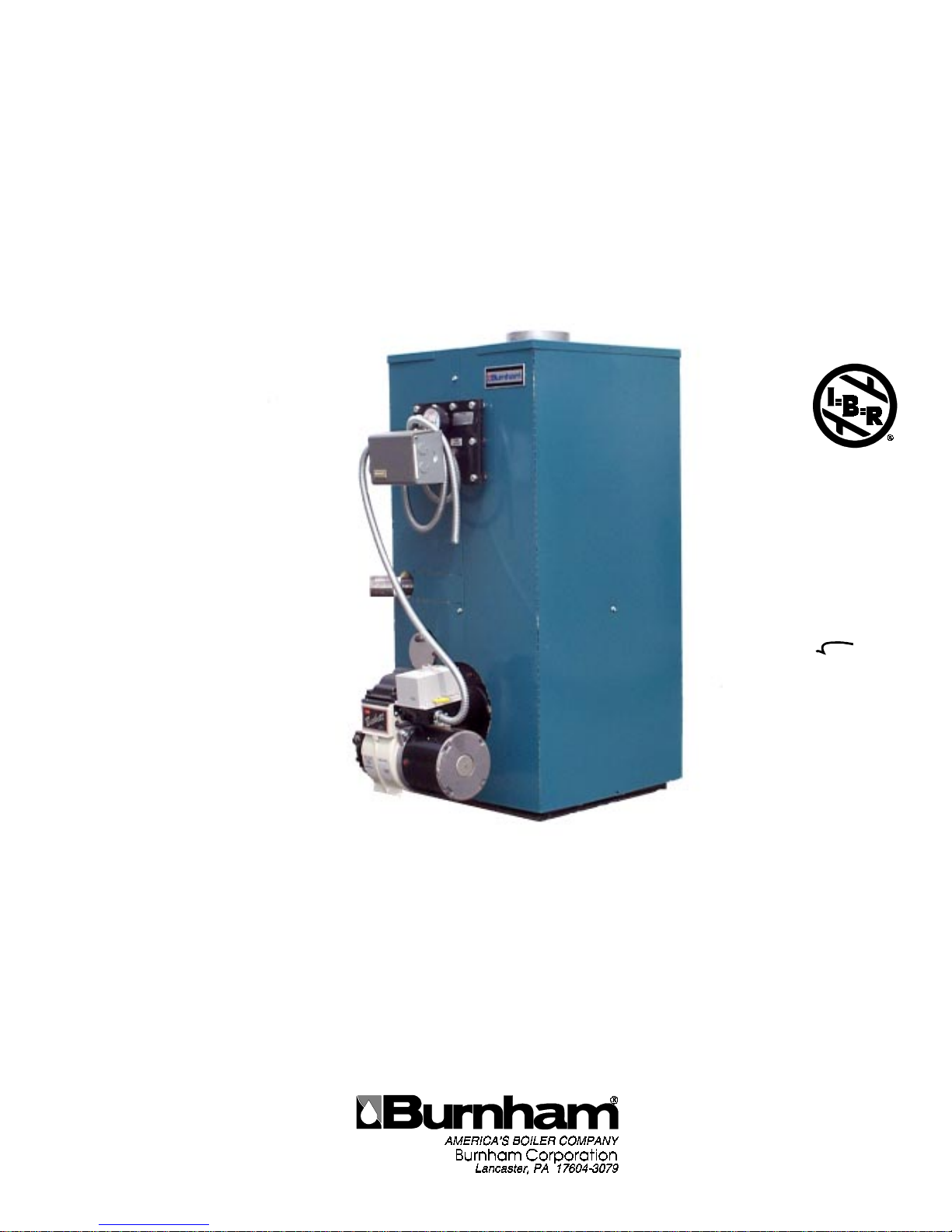
Figure 1: RSA Packaged Boiler (RSA85 / RSA135)
5
Page 6
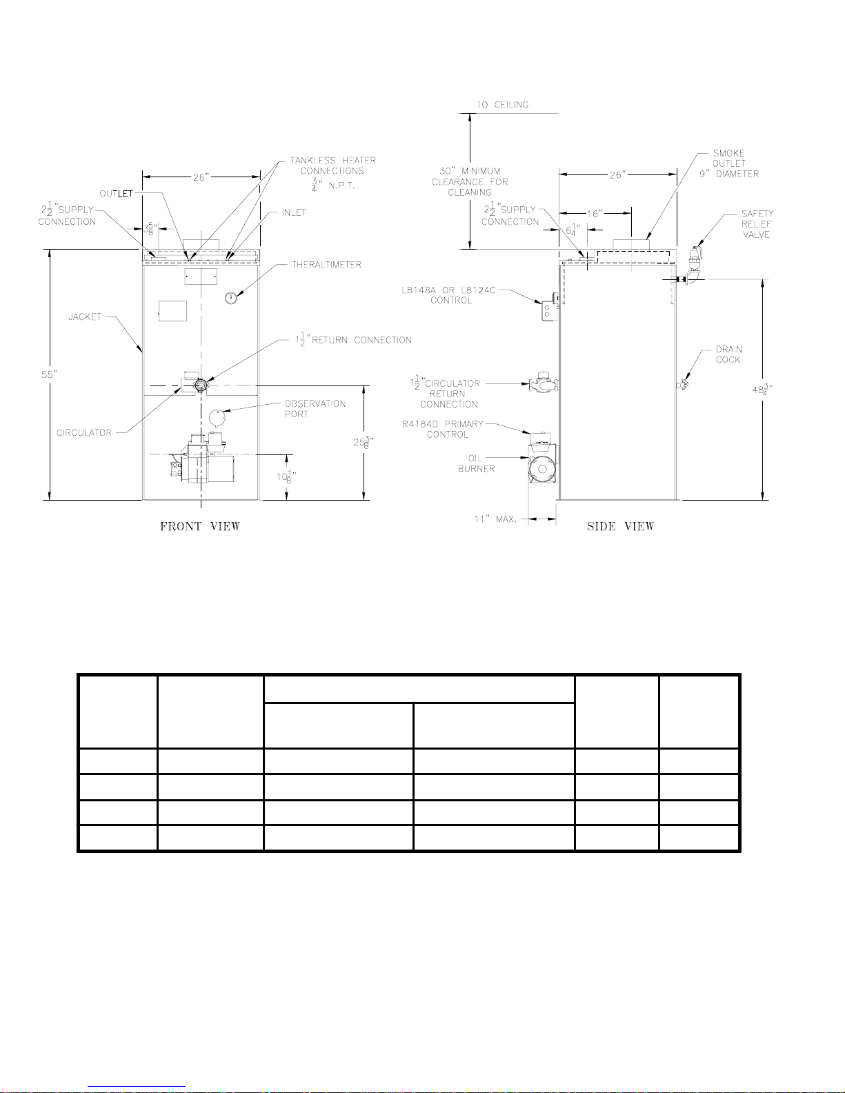
Figure 1A: RSA Packaged Boiler (RSA170 / RSA285)
Boiler
Mode l
Number
RSA170 WV-29-10
RSA195 WV-29-13A
RSA240 WV-29-16A 8 x 12 x 20 8" x 20' 37.3 660 lb.
RSA285 WV-29-19A
B are B oile r
Assembly
Minimum Chimney Sizes
In. x In . x Ft.
(height)
8 x 8 x 20 7" x 20' 42.6 600 lb.
8 x 8 x 20 8" x 20' 39.9 630 lb.
8 x 12 x 20 9" x 20' 34.6 690 lb.
In. (dia.) x Ft.
(height)
Water
Capacity
Gallons
Approx.
Shipping
We igh t
6
Page 7
I. Pre-Installation
A. INSPECT SHIPMENT carefully for any signs of
damage.
1. ALL EQUIPMENT is carefully manufactured,
inspected and packed. Our responsibility ceases
upon delivery of the crated boiler to the carrier in
good condition.
2. ANY CLAIMS for damage or shortage of shipment
must filed immediately against the carrier by the
consignee. No claims for variances from, or
shortage in orders, will be allowed by the manufacturer unless presented within sixty (60) days after
receipt of goods.
B. LOCATE BOILER in front of final position before
removing crate.
1. LOCATE so that smoke pipe connection to chimney will be short and direct. BOILER IS NOT
SUITABLE FOR INSTALLATION ON COMBUSTIBLE FLOOR unless combustible floor shield,
supplied by Burnham, is used. DO NOT install on
carpeting.
2. FOR BASEMENT INSTALLATION, provide a
solid base, such as concrete, if floor is not level, or
if water may be encountered on floor around boiler.
3. PROVIDE SERVICE CLEARANCE of at least 48”
from the front of the jacket for servicing of burner
and removal of tankless heater.
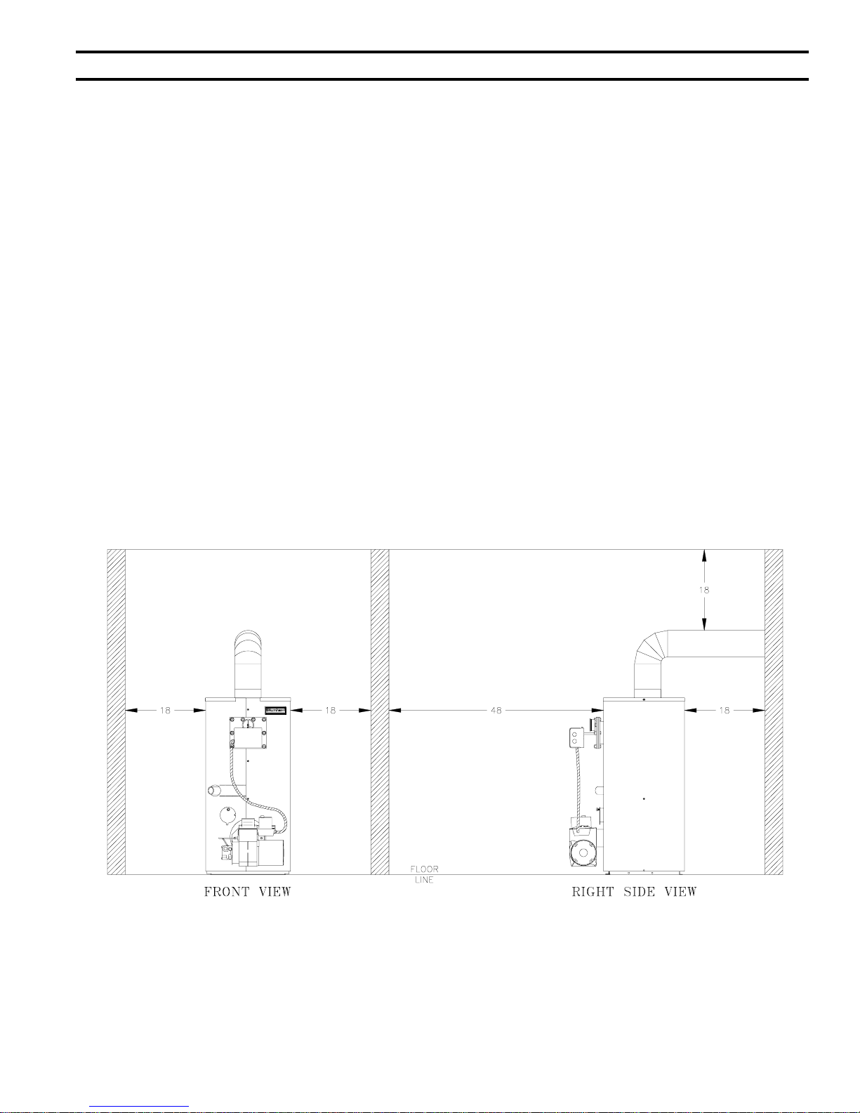
For minimum clearances to combustible materials. See
Figure 2.
Figure 2: Minimum Clearances to Combustible Materials
NOTE:
1. Listed clearances comply with American National Standard ANSI/NFPA 31, Installation of Oil Burning Equipment.
2. RSA boilers can be installed in rooms with clearances from combustible material as listed above. Listed clearances can not
be reduced for alcove or closet installations.
3. For reduced clearances to combustible material, protection must be provided as described in the above ANSI/NFPA 31
standard.
7
Page 8

C. PROVIDE AIR SUPPLY AND VENTILATION to
accommodate proper combustion. If natural ventilation is inadequate, provide a screened opening or duct
from the boiler room to the outside. The opening or
duct must be sized so the boiler input will not exceed
4,000 BTUH/Sq. In. of free area. If other air consuming appliances are near the boiler, the air inlet should
be larger. Consult respective manufacturers.
D. VENTILATION AIR must be provided to maintain
the ambient temperature at safe limits. Local and
national codes may apply and should be referenced.
1. In unconfined spaces (basement) in buildings of
conventional frame, brick, or stone construction,
infiltration normally is adequate to provide air for
ventilation.
2. In confined spaces, two permanent openings, one
near the top of the enclosure and one near the
bottom, shall be provided. Each opening shall have
a free area of not less than 1 sq. inch per 1000
BTUH of the total input of all appliances in the
space.
3. PROVIDE COMBUSTION AND VENTILATION
AIR. Local code provisions may apply and should be
referenced.
than 50 ft3/1000 BTU per hour then the space is
considered a confined space.
D. For boiler located in an unconfined space of a conven-
tionally constructed building, the fresh air infiltration
through cracks around windows and doors normally
provides adequate air for combustion and ventilation.
E. For boiler located in a confined space or an unconfined
space in a building of unusually tight construction,
provide outdoor air with the use of two permanent
openings which communicate directly or by duct with
the outdoors or spaces (crawl or attic) freely communicating with the outdoors. Locate one opening within 12
inches of top of space. Locate remaining opening
within 12 inches of bottom of space. Minimum
dimension of air opening is 3 inches. Size each
opening per following:
1. Direct communication with outdoors. Minimum
free area of 1 square inch per 4,000 BTU per hour
input of all equipment in space.
2. Vertical ducts. Minimum free area of 1 square
inch per 4,000 BTU per hour input of all equipment in space. Duct cross-sectional area shall be
same as opening free area.
3. Horizontal ducts. Minimum free area of 1 square
inch per 2,000 BTU per hour input of all equipment in space. Duct cross-sectional area shall be
same as opening free area.
Alternate method for boiler located within confined
space. Use indoor air if two permanent openings
communicate directly with additional space(s) of
sufficient volume such that combined volume of all
spaces meet criteria for unconfined space. Size each
opening for minimum free area of 1 square inch per
1,000 BTU per hour input of all equipment in spaces,
but not less than 100 square inches.
A. Determine volume of space (boiler room). Rooms
communicating directly with the space in which the
appliances are installed, through openings not furnished with doors, are considered a part of the space.
Volume(ft3) = Length(ft) x Width(ft) x Height(ft)
B. Determine total input of all appliances in the space.
Add inputs of all appliances in the space and round the
result to the nearest 1000 BTU per hour.
C. Determine type of space. Divide Volume by total input
of all appliances in space. If the result is greater than
or equal to 50 ft3/1000 BTU per hour, then it is
considered an unconfined space. If the result is less
F. Louvers and Grilles of Ventilation Ducts
1. All outside openings should be screened and
louvered. Screens used should not be smaller than
1/4 inch mesh. Louvers will prevent the entrance of
rain and snow.
2. Free area requirements need to consider the
blocking effect of louvers, grilles, or screens
protecting the openings. If the free area of the
louver or grille is not known, assume wood louvers
have 20-25 percent free area and metal louvers and
grilles have 60-75 percent free area.
3. Louvers and grilles must be fixed in the open
position, or interlocked with the equipment to open
automatically during equipment operation.
8
Page 9

II. Knock-Down Boiler Assembly
A. REMOVAL OF BOILER.
1. Remove, all boiler to skid, hold down fasteners.
Refer to Figure 3.
2. Carefully walk boiler to the edge of skid. Tilt the
boiler back, allowing an edge to rest on the floor,
and remove the skid.
Figure 3: Base on Skid
B. TEST HEAT EXCHANGER FOR LEAKS before
proceeding with jacket assembly. Heat exchanger,
canopy, and base are preassembled.
1. Install pressure gauge supplied, a hose to the city
water and a valve in the supply tapping. Plug
remainder of tappings.
2. Fill boiler with water and apply a pressure of at
least 10 psig but no more than 30 psig.
H. INSTALLING THE JACKET
1. Before jacket can be secured to boiler assembly
tankless heater coil or blank plate must be attached.
Using rubber gasket and bolts provided secure
heater coil or blank plate to boiler extension by
inserting the bolts from the backside of the extension. Refer to Figure 4.
9
Page 10

Figure 5: Burner Mounting
10
Page 11

11
Figure 6: RSA Jacket Assembly
Page 12

III. Water Piping and Trim
WAR N I NG
Failure to properly pipe boiler may result in improper ope ration and dam age to boiler or
structur e .
Oxyg en contam ination of boi le r wa t e r will c a use c orrosion of iron a nd steel bo iler
c ompone nts, and can lead to boiler failure. Burnh am's Standard Warranty does no t cover
problems caused by oxygen contamination of boiler water or scale (lime) build-up c aused
by freque nt a ddition of water.
A. Design a piping system and install boiler which will
prevent oxygen contamination of boiler water and
frequent water additions.
1. There are many possible causes of oxygen contamination such as:
a. Addition of excessive make-up water as a result
of system leaks.
b. Absorption through open tanks and fittings.
c. Oxygen permeable materials in the distribution
system.
2. In order to insure long product life, oxygen sources
should be eliminated. This can be accomplished by
taking the following measures:
a. Repairing system leaks to eliminate the need for
addition of make-up water.
b. Eliminating open tanks from the system.
c. Eliminating and/or repairing fittings which
allow oxygen absorption.
d. Use of non-permeable materials in the distribu-
tion system.
e. Isolating the boiler from the system water by
installing a heat exchanger.
WARN ING
System supply and return piping must
be conn ected to corr ect boiler pipe.
Burnham recommends sizing the
s ystem circulator to su pply sufficient
flow (GPM) to allow a 20°F temper ature
diff eren tial i n the s ys tem . When s izing
the system circu lator, the pressur e
drop of all radiators, baseboard and
radiant tubing and a ll connecting
piping must be considered.
3. Connect System supply and return piping to boiler.
See Figures 8 and 9. Also, consult I=B=R Installation and Piping Guides. Maintain minimum ½
inch clearance from hot water piping to combustible materials.
a. If this boiler is used in connection with refrig-
eration systems, the boiler must be installed so
that the chilled medium is piped in parallel with
the heating boiler using appropriate valves to
prevent the chilled medium from entering the
boiler. See Figure 7. Also, consult I=B=R
Installation and Piping Guides.
b. If this boiler is connected to heating coils
located in air handling units where they may be
exposed to refrigerated air, the boiler piping
must be equipped with flow control valves to
prevent gravity circulation of boiler water
during the operation of the cooling system.
c. If boiler is used with an Alliance™ Indirect-
Fired Domestic Water Heater, install the
Alliance™ as a separate heating zone. Refer to
the Alliance™ Installation, Operating, and
Service Instructions for additional information.
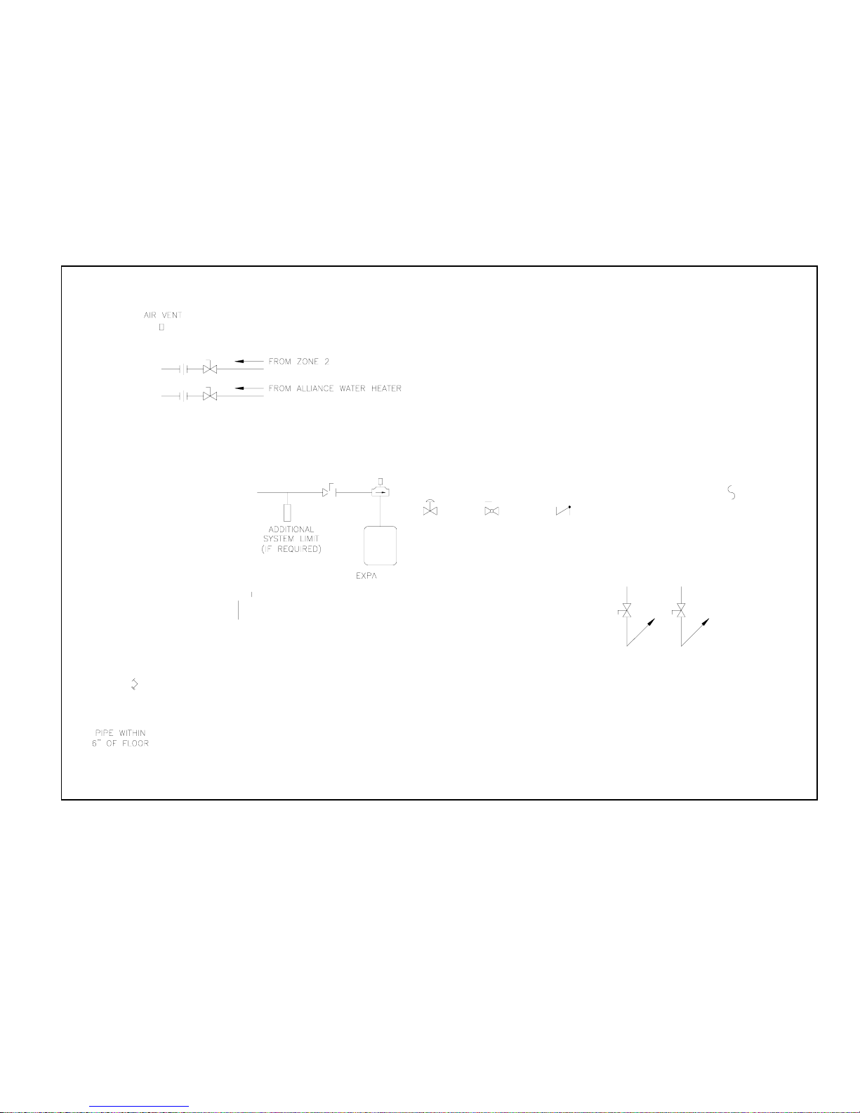
d. Use a system bypass if the boiler is to be
operated in a system which has a large volume
or excessive radiation where low boiler water
temperatures may be encountered (i.e. converted
gravity circulation system, etc.) The bypass
should be the same size as the supply and
return lines with valves located in the bypass
and return line as illustrated in Figure 10 in
order to regulate water flow for maintenance of
higher boiler water temperature. Set the bypass
and return valves to a half throttle position to
start. Operate boiler until the system water
temperature reaches its normal operating range.
Adjust the valves to maintain 180°F to 200°F
boiler water temperature and greater the 120°F
return temperature. Adjust both valves simultaneously. Closing the boiler return valve while
opening the bypass valve will raise the boiler
return temperature. Opening the boiler return
valve while closing the by-pass valve will lower
the boiler return temperature.
e. A water boiler installed above radiation level
must be provided with a low water cutoff device
as part of the installation.
12
Page 13
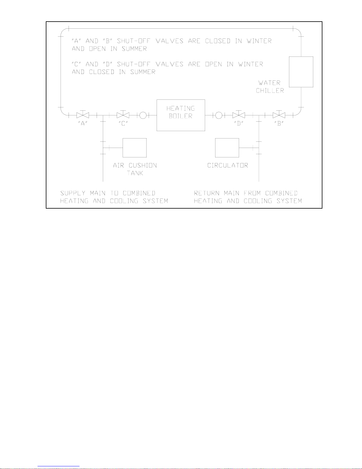
Figure 7: Recommended Piping for Combination Heating and Cooling (Refrigeration) System
B. Install Pressure Relief Valve. See Figures 8 and 9.
Pressure Relief Valve must be installed with spindle in
the vertical position. Installation of the relief valve
must be consistent with ANSI/ASME Boiler and
Pressure Vessel Code, Section IV.
C. Install Drain Valve in return piping. See Figures 8
and 9.
D. Oil, grease, and other foreign materials which accumu-
late in new hot water and a new or reworked system
should be boiled out, and then thoroughly flushed. A
qualified water treatment chemical specialist should be
consulted for recommendations regarding appropriate
chemical compounds and concentrations which are
compatible with local environmental regulations.
E. After the boiler and system have been cleaned and
flushed, and before refilling the entire system add
appropriate water treatment chemicals, if necessary, to
bring the pH between 7 and 11.
13
Page 14
14
Figure 8: Recommended Boiler Piping for Circulator Zoned Heating Systems
Page 15

15
Figure 9: Boiler Piping for Zone Valve Zoned Heating Systems
Page 16

F. CONNECT TANKLESS HEATER PIPING AS
SHOWN IN FIGURE 11. See Table 1 for Tankless
Heater Rating.
WAR N I NG
In stall autom atic mixing valve at tankl ess
heater outlet to avoid risk of burns or
scalding due to excessive ly hot water at
fixtures. Adjus t and m aintain the mixing
valve in accor dance wi th the ma nufa cturer's
instructions. Do not operate tankless
heater without mixing valve.
THE FOLLOWING GUIDELINES SHOULD BE
FOLLOWED WHEN PIPING THE TANKLESS HEATER:
1. FLOW REGULATION — If flow through the
heater is greater than its rating, the supply of
adequate hot water may not be able to keep up with
the demand. For this reason a flow regulator
matching the heater rating should be installed in
the cold water line to the heater. The flow regulator
should preferably be located below the inlet to the
heater and a minimum of 3’ away from the inlet so
that the regulator is not subjected to excess temperatures that may occur during “off” periods when
it is possible for heat to be conducted back through
the supply line. The flow regulator also limits the
flow of supply water regardless of inlet pressure
variations in the range of 20 to 125 psi.
2. TEMPERING OF HOT WATER — Installation of
an automatic mixing valve will lengthen the
delivery of the available hot water by mixing some
cold water with the hot. This prevents the possibility of scalding hot water at the fixtures. In addition,
savings of hot water will be achieved since the user
will not waste as much hot water while seeking a
water temperature. Higher temperature hot water
required by dishwashers and automatic washers is
possible by piping the hot water from the heater
prior to entering the mixing valve. The mixing
valve should be “trapped” by installing it below the
cold water inlet to heater to prevent lime formation
in the valve. Refer to Figure 11.
3. FLUSHING OF HEATER — All water contains
some sediment which settles on the inside of the
coil. Consequently, the heater should be periodically backwashed. This is accomplished by installing hose bibs as illustrated and allowing water at
city pressure to run into hose bib A, through the
heater, and out hose bib B until the discharge is
clear. The tees in which the hose bibs are located
should be the same size as heater connections to
minimize pressure drop.
4. HARD WATER — A water analysis is necessary
to determine the hardness of your potable water.
This is applicable to some city water and particularly to well water. An appropriate water softener
should be installed based on the analysis and
dealer’s recommendation. This is not only beneficial to the tankless heater but to piping and fixtures
plus the many other benefits derived from soft
water.
Figure 10: Recommended System Bypass Piping
16
Page 17

Figure 11: Schematic Tankless Heater Piping
Table 1: Tankless Heater Ratings
Boiler Model
S350 S375
GPM PSID GPM PSID
R SA(H )85 & 110 3 1 2 3½ 1 5
RSA110(H)125 & 135 3¼ 16
RSA1 25 & 135 3½ 1 9
3¾ 2 5
STD. #7524 OPT. #7530
Boil er Model
G PM PSID G PM PS ID
RSA170 3¾ 25½ 4 26½
RSA195, 240, & 285 4 29 4¼ 31
17
Page 18

IV. Venting
A. General Guidelines.
1. Vent system installation must be in accordance with
these instructions and applicable provisions of local
building codes. Contact local building or fire
officials about restrictions and installation inspection in your area.
2. The RSA Series is designed to be vented into a
fireclay tile-lined masonry chimney or chimney
constructed from type-L vent or a factory built
chimney that complies with the type HT requirements of UL103. The chimney or vent pipe shall
have a sufficient draft at all times, to assure safe
proper operation of the boiler. See Figure 12 for
recommended installation.
a. Install a draft regulator (supplied by installer)
following the instructions furnished with the
regulator. See Figure 13 for alternate regulator
locations.
b. With any new or replacement installation the
chimney has to be considered. Chimneys that
have a high heat loss become less suitable as the
heat loss of the home goes down and the
efficiency of the boiler goes up. Most homes
have a chimney appropriate for the fuel and the
era in which the home was built. That may
have been a coal fired or an inefficient oil fired
boiler built into a home without insulation or
storm windows. With increasing fuel prices that
home probably has been insulated and fitted
with storm windows so that the heat loss of the
home has been reduced. This requires less fuel
to be burned and sends less heat up the chimney.
A new boiler probably has a higher efficiency
than the boiler being replaced. That probably
means that the stack temperature from the new
boiler will be lower than that from the old boiler
and with less room air being drawn up the
chimney to dilute the stack gases. The combination of a large uninsulated chimney, reduced
firing rate, reduced firing time, lower stack
temperature and less dilution air can, in some
cases, contribute to the condensing of small
amounts of water vapor in the chimney. Such
condensation, when it occurs, can cause chimney deterioration. In extreme cases, the chimney may have to be lined to insulate the chimney
and thus prevent the condensation. The
addition of dilution air into the chimney may
assist in drying the chimney interior surfaces.
A massive chimney on a cold, or exposed
outside wall may have produced adequate draft
when it was fired with a higher input and
greater volumes of heated gases. With reduced
input and volume, the draft may be severely
affected. In one instance our research showed a
new chimney of adequate sizing produced only .035” W.C. after 30 minutes of continuous firing
at 13.0% CO2. Outside wall chimneys take
longer to heat up and can have .00” W.C. draft
at burner start-up. You may have to consider a
special alloy chimney flue liner with insulation
around it and stabilizing draft cap or even a
draft inducing fan in severe cases.
c. For the same reasons as in (2.) above, heat
extractors mounted into the breeching are not
recommended.
3. For minimum clearances to combustible materials
refer to Figure 2.
18
Page 19

Figure 12: Recommended Smokepipe Arrangement and Chimney Requirements
Figure 13: Draft Regulator Locations
19
Page 20

V. Electrical
DANGER
Positively assu re all el ectrical connections are unpow ered before attem pting installation or
service of electrical components or connections of the boiler or bui lding. Lock out all electri cal
boxes wi th padlock o nce power is turn ed off.
WARN ING
Failure to properly wire electrical connections to the boiler may result in serious physical
harm.
Electrical power may be from more than one source. Make sure all power is off b efore
attempting any electrical work.
Each boiler must be protected with a properly sized fused disconnect.
Never jump out or make inoperative any safety or operating controls.
The wiring diagrams contained in this manual are for reference purposes only. Refer to the
wiring diagram of any controls used with the boiler. Read, understand and follow all wiring
inst ructions su pplied with th e controls.
A. General
1. Install wiring and electrically ground boiler in
accordance with requirements of the authority
having jurisdiction, or in absence of such requirements the National Electrical Code, ANSI/NFPA
70, and/or the CSA C22.1 Electric Code.
2. A separate electrical circuit should be run from the
main electrical service with a fused disconnect
switch in the circuit.
3. Wiring should conform to Figure 14 and/or 15.
B. System Controls and Wiring
1. Refer to National Electric Code or Local Electric
Codes for proper size and type of wire required.
Follow Code.
2. Use anti-short bushings on all wiring passing
through boiler jacket, junction boxes and/or control
boxes.
3. Use armored cable (BX) over all exposed line
voltage wiring.
4. If an Alliance indirect water heater is used, use
priority zoning. Do not use priority zoning for
Hydro-Air Systems.
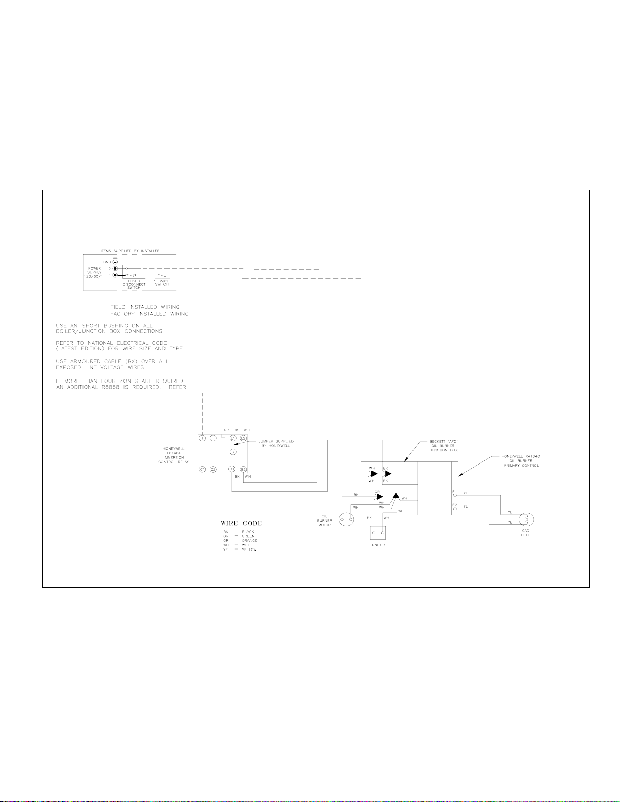
5. Single Zone System – Refer to Figure 14 or 15 of
this manual for the electrical diagram for this type
of system. Connect the system circulator wire leads
to the proper locations on the Aquastat control,
L8124C/L8148A. See Figure 14 or 15. Connect
the thermostat to the ‘T-T’ terminals on the
L8124C/L8148A control. Set thermostat heat
anticipator settings to 0.60 amps.
6. Conventional Circulator Zoned System – Refer to
Figure 16 of this manual for the electrical diagram
for this type of system.
Read, understand and follow all of the instructions
provided with the Honeywell R8888 control.
7. Conventional Zone Valve Zoned System – Refer to
Figure 17. Wiring to the most popular models of
zone valves are given in Figure 18.
Locate C1 and C2 inside the L8124C Honeywell
control. Connect the two (2) terminals to the
system circulator wire leads, supplied with boiler.
Connect the H1 and H2 terminals inside the R8889
to the ‘T-T’ terminals in the L8124C Honeywell
Control. Refer to Figure 17.
Connect the thermostat of each zone and the
circulator for that zone to R8889 panel. If an
Alliance indirect water heater is used, connect the
Alliance thermostat and circulator to the Zone 1
terminals of the R8889. Set thermostat anticipator
settings to 0.12 amps.
20
Page 21

Figure 14: “RSAL” Wiring Less Tankless, Single Circulator
Figure 15: “RSAT” or “RSAR” Wiring with Tankless, Single Circulator
21
Page 22
22
Figure 16: Circulator Zoned Wiring for Honeywell R8888
Page 23

Figure 17: Zone Valve Zoned Wiring for R8889
23
Page 24

Figure 18: Different Manufacturer’s Zone Valve Connections to Honeywell R8889
24
Page 25

NOTICE
The Burnham EC5000 Control includes a water temperature sensor. Mount this sensor to the
syste m s upply piping.
8. Burnham EC5000 Circulator Zoned System – Refer
to Figure 19 of this manual for the electrical
diagram for this type of system. Wire the system as
indicated in that diagram. Refer to the manual
provided with the Burnham EC5000 Control for
control operation and setup details.
9. Burnham EC5000 Zone Valve Zoned System –
Refer to Figure 20 of this manual for the electrical
diagram for this type of system. Wire the system as
indicated in that diagram. Refer to the manual
provided with the Burnham EC5000 for control
operation and setup details.
25
Page 26

26
Figure 19: Circulator Zoning with EC5000 Wiring Schematic
Page 27
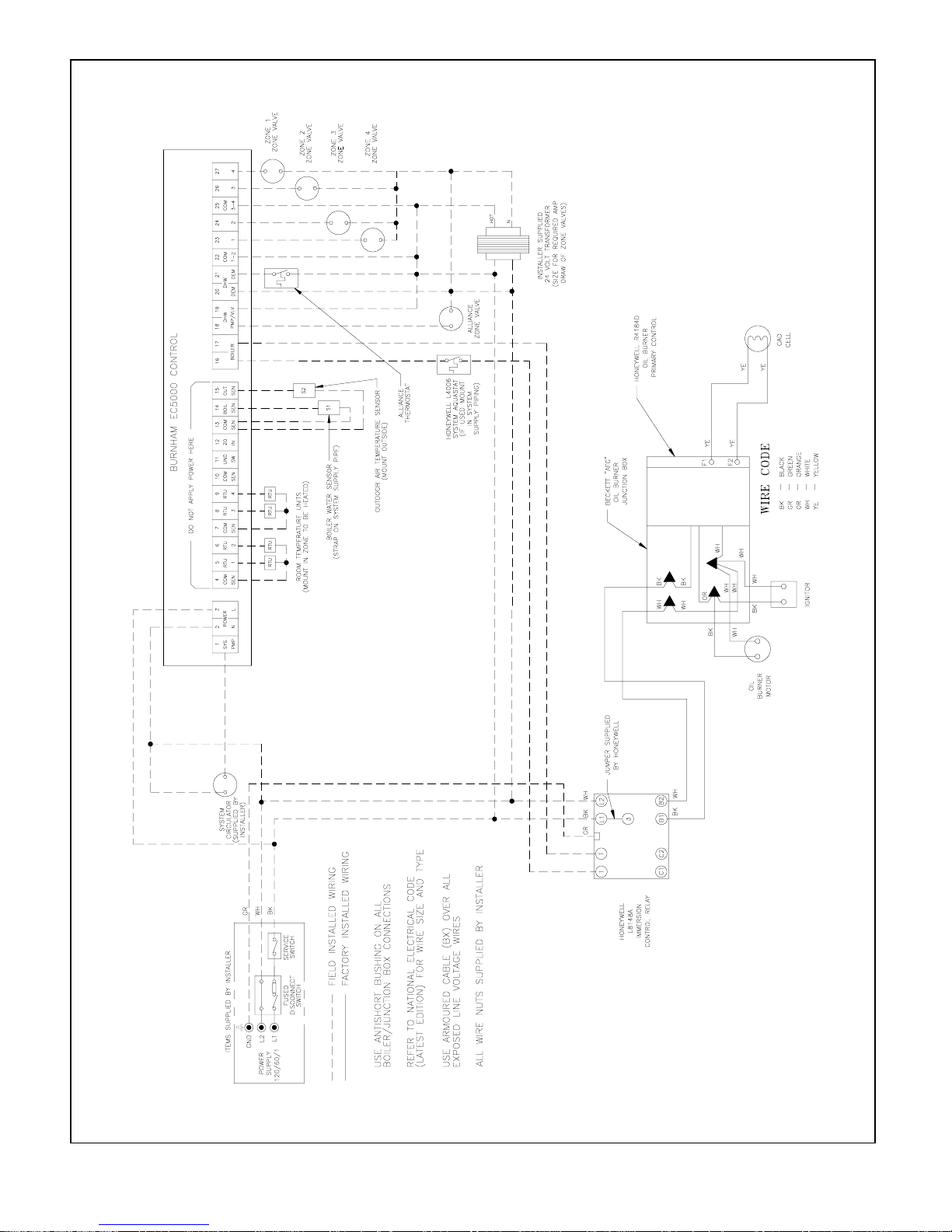
Figure 20: Zone Valve Zoned with EC5000 Wiring Schematic
27
Page 28

VI. Oil Piping
A. General.
1. Use flexible oil line(s) so that burner can be
removed without disconnecting the oil supply.
2. A supply line fuel oil filter is recommended as a
minimum for all firing rates but a pleated paper
fuel oil filter is recommended for the lowest firing
rate application to prevent nozzle fouling.
3. Use Flared fittings only. Do not use compression
fittings.
4. Use of a high efficiency micron filter (Garber or
equivalent) in addition to conventional filter is
highly recommended.
B. Single-pipe Oil Lines.
1. Standard burners are provided with single-stage
3450 rpm fuel units with the bypass plug removed
for single-pipe installations.
2. The single-stage fuel unit may be installed singlepipe with gravity feed or lift. Maximum allowable
lift is 8 feet. See Figure 21.
NO TICE
Oil piping mus t b e ab solu t e ly airtight or
leaks or loss of prime may result. Bleed line
and fuel unit com pletely.
Figure 21: Single-Pipe Installation
28
Page 29

TABLE 2: SINGLE STA GE UNITS (3450 R PM)
TWO PIPE SYSTEMS
TABLE 3: TWO-STA GE UNITS (3450 R PM)
TWO-PIPE SYSTEMS
Maximum Length of Tubing
Lift "H"
(See Figure)
"H" +"R" (See Fi gure)
3/8" OD
Tubing (3 GPH)
0' 84' 1 00'
1' 78' 1 00'
2' 73' 1 00'
3' 68' 1 00'
4' 63' 1 00'
5' 57' 1 00'
6' 52' 1 00'
7' 47' 1 00'
8' 42' 1 00'
9' 36' 1 00'
10' 31' 1 00'
11' 26' 100'
12' 21' 83'
13' --- 62'
14' --- 41'
1/2" OD
Tubing (3 GPH)
Lift "H"
"H" + "R" (Se e Figu re)
(See Figure)
Maximum Length of Tubing
3/8" OD
Tubing
0' 93' 100'
2' 85' 100'
4' 77' 100'
6' 69' 100'
8' 60' 100'
10' 52' 100'
12' 44' 100'
14' 36' 100'
16' 27' 100'
18'
---
1/2" OD
Tubing
76'
C. Two-Pipe Oil Lines
1. For two-piped systems, where more lift is required,
the two-stage fuel unit is recommended. Table 2
(single-stage) and Table 3 (two-stage) show
allowable lift and lengths of 3/8 inch and 1/2 inch
OD tubing for both suction and return lines. Refer
to Figure 22.
Figure 22: Two-Pipe Installation
29
Page 30

VII. System Start-Up
A. Verify that the venting, water piping, oil piping, and
electrical system are installed properly. Refer to
installation instructions contained in this manual.
B. Confirm all electrical, water and oil supplies are turned
off at the source and that the vent is clear from
obstructions.
C. Fill entire heating system with water and vent air from
system. Use the following procedure on a Series Loop
or multi-zoned system installed as per Figure 8 or 9.
1. Close isolation valve in boiler supply piping.
2. Isolate all circuits by closing zone valves or
balancing valves.
3. Attach a hose to bib cock located just below
isolation valve in boiler supply piping. (Note Terminate hose at a suitable floor drain or outdoor
area).
10. Open isolation valve in boiler supply piping.
11. Remove hose from bib cock.
D. CONFIRM that the boiler and system have no water
leaks.
E. CHECK CONTROLS, WIRING AND BURNER to be
sure that all connections are tight and burner is rigid.
Verify that all electrical connections have been
completed, fuses installed, that the oil tank is filled and
oil lines have been tested.
F. LUBRICATION. Follow instruction on burner and
circulator label to lubricate, if oil lubricated. Most
motors currently used on residential type burners
employ permanently lubricated bearings and thus do
not require any field lubrication. Water lubricated
circulators do not need field lubrication.
G. SET CONTROLS with burner service switch turned
“OFF”.
1. SET ROOM THERMOSTAT about 10° above
room temperature.
2. PRESS RED RESET BUTTON on R4184D Oil
Primary Control and release.
4. Starting with one circuit at a time, open zone valve
or valve.
5. Open bib cock.
6. Open fill valve (Make-up water line should be
located directly after isolation valve in boiler supply
piping between air scoop and expansion tank).
7. Allow water to flow into drain until discharge from
hose is bubble free for 30 seconds.
8. When zone is completely purged of air, close zone
valve or balancing valve. Open the zone valve for
the next zone to be purged. Repeat this step until
all zones have been purged. At completion, open
all zone valves or valves.
9. Close bib cock, continue filling the system until the
pressure gauge reads 12 psig. Close fill valve.
(Note - If make-up water line is equipped with
pressure reducing valve, system will automatically
fill to 12 psig.
3. SET HIGH LIMIT dial on L8124C/L8148A at
temperature to suit requirements of installation.
H. REMOVE GUN ASSEMBLY
1. Check nozzle size, head size, gun setting, and
positioning of electrodes. This information is
shown in Figure 23, and Tables 4 and 4A.
2. Reinstall gun assembly.
I. VERIFY OIL BURNER SETTINGS BEFORE
STARTING
1. BURNER AIR BAND AND AIR SHUTTER
SETTINGS, see Tables 4 and 4A.
2. OPEN ALL OIL LINE VALVES.
3. Attach a plastic hose to fuel pump vent fitting and
provide a container to catch the oil.
4. REMOVE GAUGE PORT PLUG from fuel pump
and install pressure gauge.
J. START OIL BURNER
1. Open vent fitting on fuel pump.
2. TURN ‘ON’ BURNER service switch and allow
burner to run until oil flows from vent fitting in a
30
Page 31

Table 4: Beckett AFG, AF, & SF Burners
Boiler Model
RSA8 5 .85 .75 x 70B 1 0 0 N/A 140
RSA110 1.10 .9 0 x 80B 8 0 N/A 140
RSA12 5 1 .25 1. 0 x 80B 7 0 N/A 14 0
RSA135 1.35 1.10 x 80B 9 0 N/A 140
RSA170 1.7 0 1.65 80 A 7 0 N/A 100
RSA195 1.9 5 2.00 80 B 7 0 N/A 100
RSA240 2.4 0 2.50 80 B 7 0 N/A 100
RSA285 2.8 5 3.00 80 B 7 0 N/A 100
Table 4A: Becket AFG Burner
Boiler Model
Firing Rate
(GPH)
Firing Rate
(GPH)
Hago
Nozzle
Hago
Nozzle
Shutter Band Head (stop screw) Pump Pressure
Shutter Band H ead (stop screw) Pump Pressure
Air Settings
Air Settings
RSAH85 .75 .65 x 80B 6 0 N/A 140
R S AH11 0 1.0 .8 5 x 8 0B 7 0 N/A 14 0
R SAH 125 1. 1 .90 x 80B 7 0 N /A 14 0
R S AH1 3 5 1 .2 5 1 . 0 x 80B 9 0 N /A 14 0
SOLID stream without air bubbles for approximately 10 seconds.
3. Close vent fitting and burner flame should start
immediately.
4. If the burner does not start immediately, check the
manual overload switch on the motor, if so
equipped, and the safety switch on the burner
primary control.
K. ADJUST OIL PRESSURE
1. Locate oil pressure adjusting screw and turn
screw until Pressure Gauge reads the correct
pump pressure required for the specific boiler.
Refer to table 4 & 4A.
2. DO NOT REMOVE PRESSURE GAUGE until
later.
L. OTHER ADJUSTMENTS
1. ADJUST THE AIR BAND AND/OR AIR SHUTTER.
Beckett Burners:
a. Adjust air supply by loosening lock screws and
moving the air shutter and if necessary the air
band. Refer to Table 4 and 4A preliminary
settings.
2. ADJUST DRAFT REGULATOR for a draft of
-.02” (water gauge) over the fire after chimney has
reached operating temperature and while burner is
running.
3. READJUST AIR BANDS on burner for a light
orange colored flame while draft over the fire is
-.02” w.c. Use a smoke test and adjust air for
minimum smoke (not to exceed #1) with a minimum of excess air. Make final check using suitable
31
Page 32

Figure 23: Electrode / Head Setting
instrumentation to obtain a CO2 of 11.5 to 12.5%
with draft of -.02” w.c. in fire box. These settings
will assure a safe and efficient operating condition.
If the flame appears stringy instead of a solid flame,
try another nozzle of the same type. Flame should
be solid and compact. After all adjustments have
been made, recheck for a draft of -.02” w.c. over the
fire.
4. TURN “OFF” BURNER and remove pressure
gauge. Install gauge port plug and tighten. Start
burner again.
M. FLAME FAILURE
The RSA boiler controls operate the burner automatically. If for unknown reasons the burner ceases to fire
and the rest button on the primary control has tripped,
the burner has experienced ignition failure. Before
pressing the rest button, call your serviceman immediately.
N. CHECK FOR CLEAN CUT OFF OF BURNER
1. AIR IN THE OIL LINE between fuel unit and
nozzle will compress when burner is on and will
expand when burner stops, causing oil to squirt
from nozzle at low pressure as burner slows down
and causing nozzle to drip after burner stops.
Usually cycling the burner operation about 5 to 10
times will rid oil line of this air.
(Non-Burnham Drawing
Copy from other Manual)
2. IF NOZZLE CONTINUES TO DRIP, repeat step
N.1. If this does not stop the dripping, remove cut
off valve and seat, and wipe both with a clean cloth
until clean. Then replace and readjust oil pressure.
If dripping or after burn persist replace fuel pump.
O. HINTS ON COMBUSTION
a. NOZZLES— Although the nozzle is a relatively
inexpensive device, its function is critical to the
successful operation of the oil burner. The
selection of the nozzle supplied with the RSA
boiler is the result of extensive testing to obtain
the best flame shape and efficient combustion.
Other brands of the same spray angle and spray
pattern may be used but may not perform at the
expected level of CO2 and smoke. Nozzles are
delicate and should protected from dirt and
abuse. Nozzles are mass produced and can vary
from sample to sample. For all of those reasons
a spare nozzle is a desirable item for a serviceman to carry.
b. FLAME SHAPE — Looking into the combus-
tion chamber through the flame plug hole, the
flame should appear straight with no sparklers
rolling up toward the top of the chamber. If the
flame drags to the right or left, sends sparklers
upward or makes wet spots on the combustion
chamber, the nozzle should be replaced. If the
condition persists look for fuel leaks, air leaks,
water or dirt in the fuel as described below.
c. FUEL LEAKS— Any fuel leak between the
pump and the nozzle will be detrimental to good
combustion results. Look for wet surfaces in the
air tube, under the ignitor, and around the air
inlet. Any such leaks should be repaired as they
may cause erratic burning of the fuel and in the
32
Page 33

extreme case may become a fire hazard.
d. AIR LEAKS— Any such leaks should be
repaired, as they may cause erratic burning of
the fuel and in extreme cases may become a fire
hazard.
There may be many possible causes of leaks in
oil lines such as:
i. Fitting leaks due to misflared tubing or
damaged fitting.
ii. Fuel line leak due to crushed or bent tubing.
iii. Filter connection leaks.
iv. Tank connection leaks.
The following actions can eliminate air leaks:
i. Bleed pump as detailed in System Start-Up
Section of this manual.
ii. Replace flare fittings.
iii. Replace oil supply line.
iv. Repair oil filter leaks
v. Replace or repair tank fittings.
e. GASKET LEAKS— If 11.5% to 12.5% CO
with a #1 smoke cannot be obtained in stack,
look for air leaks around the canopy seal. Such
air leaks will cause a lower CO2 reading in the
stack. The smaller the firing rate the greater
effect an air leak can have on CO2 readings.
f. DIRT— A fuel filter is a good investment.
Accidental accumulation of dirt in the fuel
system can clog the nozzle strainer and produce
a poor spray pattern from the nozzle.
g. WATER— Water in the fuel, in large amounts,
will stall the fuel pump. Water in the fuel
pump, in smaller amounts, will cause excessive
wear on the pump, but more importantly water
does not burn. It chills the flame, causes smoke,
and allows unburned fuel to pass through the
combustion chamber and clog the flueways of
the boiler.
h. COLD OIL— If the oil temperature approach-
ing the fuel pump is 40°F or lower, poor
combustion or delayed ignition may result. Cold
2
NOT ICE
CHEC K TEST PR OCEDURE. A v ery good
test fo r isolat ing fue l side problem s is to
d iscon nec t th e f uel s ys tem an d with a 24"
length of tubi ng, fire out of an a uxiliar y
five gallon pail o f clean, fresh, warm #2
oil from anot her sou rce. If the burner
r uns suc cess fully w hen dra wing out of
the a uxili ary pa il th en th e p rob le m i s
isolated to the fuel or fuel lines being
used on the jo bsite.
oil is harder to atomize at the nozzle. Thus, the
spray droplets get larger and the flame shape
gets longer. An outside fuel tank that is above
grade or has fuel lines buried in the ground
above the frost line is a good candidate for cold
oil. The best solution is to place the tank and oil
lines in the ground below the frost line.
i. HIGH ALTITUDE INSTALLATIONS
Typically, the rule to use for high altitudes is to
increase the air supply by 4% per each 1000 ft.
above 2000 ft. altitude from sea level. This
means that the air setting will have to be higher
than the calibration marks in proportion to the
altitude. Use instruments and set for 11.5 to
12.5% CO2.
j. START-UP NOISE — Late ignition is the cause
of start-up noises. If it occurs recheck for
electrode settings, flame shape, air or water in
the fuel lines.
k. SHUT DOWN NOISE — If the flame runs out
of air before it runs out of fuel, an after burn
with noise may occur. That may be the result of
a faulty cut-off valve in the fuel pump, or it may
be air trapped in the nozzle line. It may take
several firing cycles for that air to be fully
vented through the nozzle. Water in the fuel or
poor flame shape can also cause shut down
noises.
P. TEST CONTROLS
1. CHECK THERMOSTAT OPERATION. Raise and
lower thermostat setting as required to start and
stop burner.
2. VERIFY PRIMARY CONTROL SAFETY FEATURES using procedures outlined in Instructions
furnished with control (See back of Control Cover)
or Instructions as follows:
33
Page 34

a. Simulate flame failure:
• Follow the starting procedure to turn on the
burner.
• Close the hand valve in the oil supply line.
• Safety switch should lock out in approxi-
mately 15 seconds. Ignition should stop
and oil valve should close. Blower will stop
after postpurge period.
• Push red reset button to reset safety switch.
b. Simulate ignition failure:
• Follow the starting procedure to turn on the
burner, but do not open the oil supply hand
valve.
• Safety switch should lock out in approxi-
mately 15 seconds. Ignition and motor
should stop and oil valve should close.
• Push red reset button to reset safety switch.
c. Simulate power failure:
• Follow the starting procedure to turn on the
burner.
• With the burner running, turn off the power
to the system by tripping the circuit breaker
or removing the fuse.
• Burner should stop.
• Restore power. Burner should start.
3. VERIFY HIGH LIMIT OPERATION.
a. Adjust thermostat to highest setting.
b. Observe temperature gauge. When temperature
is indicated, adjust limit to setting below
observed temperature. Burner should stop.
c. Adjust limit to setting above observed tempera-
ture. Burner should start.
4. CHECK LOW WATER CUTOFF (if so equipped).
a. Adjust thermostat to highest setting.
b. With boiler operating, open drain valve and
slowly drain boiler.
c. Burner should stop when water level drops
below low water cutoff probe. Verify limit,
thermostat or other controls have not shut off
boiler.
d. Adjust thermostat to lowest setting. Refill
boiler.
Q. Boiler is now ready to be put into service.
A leaky system will increase the volume of make-up
water supplied to the boiler which can significantly
shorten the life of the boiler. Entrained in make-up
water are dissolved minerals and oxygen. When the
fresh, cool make-up water is heated in the boiler the
minerals fall out as sediment and the oxygen escapes
as a gas. Both can result in reduced boiler life. The
accumulation of sediment can eventually isolate the
water from contacting the steel. When this happens
the steel in that area gets extremely hot and eventually
cracks. The presence of free oxygen in the boiler
creates a corrosive atmosphere which, if the concentration becomes high enough, can corrode the steel
through from the inside. Since neither of these failure
types are the result of a manufacturing defect the
warranty does not apply. Clearly it is in everyone’s
best interest to prevent this type of failure. The
maintenance of system integrity is the best method to
achieve this.
d. Adjust thermostat to lowest setting. Adjust limit
to desired setting.
34
Page 35

INSTALLATION INSTRUCTIONS FOR SHIELD REQUIRED FOR COMBUSTIBLE FLOOR
This shield for combustible floors is intended for use only with the following Burnham oil-fired boilers:
Use Part Number 6183504 for the following models:
RSA(H)85 RSA(H)110 RSA(H)125 RSA(H)135
ADDS 4-3/16” TO BOILER HEIGHT
Use Part Number 6183505 for the following models:
RSA170 RSA195 RSA240 RSA285
ADDS 5-3/8” TO BOILER HEIGHT
1) Place shield on combustible floor with “TOP” surface
upward and “FRONT” surface directly below the
expected position of the oil burner.
2) Locate shield such that clearances to combustible walls
are as indicated in Figure 24. These dimensions will
assure that the boiler jacket will be at least 18” from the
side and rear walls and 48” from the front wall, as
required by ANSI/NFPA 31.
3 ) Fasten shield to combustible floor to keep shield from
shifting position during setting of boiler.
4) Set boiler squarely on top of shield such that base plate
of boiler rests flat on top surface of shield and does not
over-hang shield on any side. Confirm clearance to
combustible walls. Refer to Figure 2.
5 ) Do not enclose boiler (including shield) on all four
sides. Boiler may be enclosed on any three sides while
maintaining minimum clearance shown in Figure 24
for each of those three sides.
Figure 24
35
Page 36

VIII. Service and Cleaning
NOTIC E
BURNER SHUTDOWN: Open Service
Switch to turn off burner.
Manual Oil Supply Valve should be closed
and E lectric Service to boiler turned off if
bo ile r will not be operated for an exte nded
period of time.
A. General. Inspection service and cleaning should be
conducted annually. Turn off electric power and close
oil supply valve while conducting service or maintenance.
B. Firetubes and Combustion Chamber. (See Figure 25)
1. CLEAN THE FIRETUBES
a. Disconnect electric to burner and remove stack.
b. For access to the firetubes, pull top jacket panel
off. Loosen wing nuts, that hold canopy down.
Without taking wing nuts off carriage bolts,
disengage bolts from slots on tubesheet. Pull
canopy off.
c. Remove turbulators.
d. Using a firetube brush clean firetubes. DO NOT
extend brush past the end of the bottom
tubesheet.
e. Assemble the boiler in reverse order.
Units should be cleaned at least once a year, preferably
at the end of each heating season.
It is not necessary to remove burner to clean boiler.
Brush, scrape, or vacuum from top.
Figure 25: Cleaning of RSA Boiler
36
Page 37

IX. Repair Parts
All RSA Repair Parts may be obtained through your local Burnham Wholesale distributor. Should you
require assistance in locating a Burnham distributor in your area, or have questions regarding the availability
of Burnham products or repair parts, please contact your Burnham Regional Sales Office as listed below.
Burnham Corporation Regional Offices
A. Burnham Corporation - Centr al & Wes tern R egio ns
P.O. Box 3079
La ncaster, PA 17604-3079
Phone: (717) 481-8400
FAX: (717) 481 -8408
B. Burnham Sales Cor poration - Northeast Region
19 -27 Mystic Av enue
Somerville, MA 02145
Phone: (617) 625-9735
FAX: (617) 625 -9736
C. Burnham Corporation - Metropolitan Region
P.O. Box 3079
Lancaster, PA 17604-3079
Phone: (717) 481-8400
FAX: (717) 481-8409
D. Burnham Co rporation - Mid-Atlantic Region
P.O. Box 3079
La ncaster, PA 17604-3079
Phone: (717) 481-8400
FAX: (717) 481 -8409
Contact Regional Office Indicated for your State
Alabama A Nebraska A Oregon A
Alask a A Nevada A P e n nsylvania D
Arizona A New H amps h ir e B Rhode I sland B
Arkansas A New J er sey South Car oli na A
Californ ia
Colora do A
Connecticut B
Delawar e D
Florida A
A
Atlan tic, Burlin gt on, Camd en,
Ca pe May, C umberla nd,
Glou cester, Mercer,
Monm outh, O ce an, S a le m
Co unt ies
South Dak ota A
Tennessee A
D
Te xas A
Utah A
Vermont B
Georgi a A
Hawaii A New Mexico A
Ida ho A New York
Illinois A
Indiana A
Iowa A
Kansas A
Kentuc ky A
Loui sia na A N orth Car olina A West Virginia D
Maine B North Dak ota A Wis consin A
M aryla nd D Oh io Wy omi ng A
Ma ss ach use tts B
Mic h igan A
Minnes o t a A
M issis sippi A
Missouri A
Montana A Okl ahoma A Canada A
All other Counties
Albany, Fulton , Montgom ery,
Re nss ela er, S ara to ga, Princ e Wil liam Counties
Sch enect ady, Schohar ie, All other Co unties
Warren, Washington Counties
All O the r C o unt ies
Athens, Belmont, Gallia,
Jefferson, Lawrenc e, M eig s,
Monro e, an d Was hing ton
Co unt ies
All other Counties
C Virg inia
Arlington,Ac comack,Cl arke,
Fairfax,Frederick,Fauquier,
Loudoun , Northampto n a nd
B
Washington A
C Washington, D.C. D
D
A
D
A
37
Page 38

REPAIR PARTS
NOTE: When ordering parts always give the serial number and model number shown on the boiler. Also provide the name of
the part(s) shown below:
Figure 26: RSA85-135 Bare Boiler Repair Parts
38
Page 39

ITEM NO. QTY. DESCRIPTIO N PART NO.
1 2 Wing Nut, 1/4 - 20 80860910
2 10 Washer, Flat 1/4 (SAE) 80860633
3 1 Canopy Assembly 6113509
4 2 1/2" Thick x 1" x 12-3/8" Cerafelt Strip 9206005
5 2 1/2" Thick x 1" x 13-3/8" Cerafelt Strip 9206005
6 2 Carriage Bolt, 1/4 - 20 x 3" Lg. 80860111
7
8 1 Heat Exchanger As sembly
9 10 SA307B 3/8-16 x 1-1/4" Bolt 80861360
10 1 Tankless Heater Gasket 8206036
11 1 Tapped Heater C over Plate 7036030
12 1
13 10 Washer, Flat (USS), 3/8" 80860600
14 10 Hex Nut, 3/8 - 16, Steel, Plain 80860400
15 2 1/2" Thick x 2" x 13-3/4" Cerafel t Strip 9206003
16 2 1/2" Thick x 2" x 18-1/2" Cerafel t Strip 9206003
17 1 Combustion Chamber 8203006
18 1 Cerablanket 8203512
19 1 Base As sembly 6183508
20 4 Machine Screw, Hex Head, 1/4 - 2 x 1/4" 80860810
'A'
Turbulat or 8113501
'B '
Tank less Heater Coil, (Standard S350) 6036038
Tankless Heater Coil, (Optional S375) 6036039
21 4 Hex Nut, 1/4 - 20 (H eavy Hex) 80860407
BOILER MODEL
RSA85 12 603350112
RSA110 16 6033501 16
RSA125 12 603350212
RSA135 16 603350216
'A' 'B'
39
Page 40

NOTE: When ordering parts always give the serial number and model number shown on the boiler. Also provide the name of
the part(s) shown below:
Figure 27: RSA170-285 Boiler Repair Parts
40
Page 41

ITEM NO. D ESCRIPTION PART NO.
1 Jacket Top Pa nel Asse mbly 60435022
2 Canopy As sembl y 6113510
3 ½" Thick x 1" x 2 3" Ceraf elt S trip 9206005
4 ½" Thick x 1" x 1 7" Ceraf elt S trip 9206005
5 Turbulator, See
6 Tank l ess He a te r G ask et 8036025
#752 4 Tan kless H eat er As sem bly 6036015
7
#753 0 Tan kless H eat er As sem bly 6036016
8 Tapp e d H eat er C o ver P la te 7033501
9 Heat Exchanger Assembly
10 ½ x 2" x 25" C er afelt S trip 9206003
11 ½ x 2" x 2 1" Ceraf elt S tr ip 9206003
12 Co mb us ti on Ch a mb e r 8203003
13 Bloc k I nsu l ati o n As se m bly Supplied with Item #12
14 Jac ket Le ft S i de P a n el As se m bly 60435061
15 Ja c ket U p per Fr o nt P a n el As se m bly 60435033
16 Ja c ket L o wer Fr o nt P a n el As se m bly 60435042
17 Base As sembly 6186304
18 Ja c ket R e ar Pa n el A sse m bl y 60435071
19 Jac ket R ig ht S i de Pa n el As sem bl y 60435051
'A' fo r Q u a nt ity 6113504
'B'
Boiler Model 'A ' 'B'
RSA170 10 6306332
RSA195 13 6306329
RSA240 16 6306309
RSA285 19 6306310
41
Page 42

ITEM DESCRIPTION PART NUMBER
1 Jacket Top Panel 60435086
2
3 Temperature / Pressure Gauge 8056169U
4
5 Observation Port Cover / Hardware 8026015
6 Burner Primary Control, R4184D1027 80160473
Jacket Wrap-A-Round Panel, RSA85/110 60435087
Jacket Wrap-A-Round Panel, RSA125/135 60435088
Honeywell L8148A1090 Hi-Limit Control 80160449U
Honeywell L8124C1102 Limit Control 80160406
42
Page 43

SERVICE SCHEDULE
DATE SERVICE PERFORMED
43
Page 44

BECKETT BURNER PARTS LIST FOR RSA SERIES STEEL BOILERS
FOR REPLACEMENT OIL BURNER PARTS, CONTACT YOUR WHOLESALER OR THE BURNER
MANUFACTURER:
R. W. BECKETT CORP.
38251 CENTER RIDGE RD.
P. O. BOX 1289
ELYRIA, OHIO 44036
1-800-645-2876
NOTE: When ordering parts always give the serial and model numbers shown on the boiler and burner. Also, provide the
name of the part(s) and part(s) number as listed below.
Boiler Model RS A85 RSA110 RSA125 RSA135
Burner Model AFG AFG AFG AFG
Air Tube Com bina tion
Spec. No.
1) Air Band
Air Band Nut
Air Band Screw
2) Air Shutter
Ai r Shu t ter Scre w
6) Blower
7) Bulkhead Fitting
8 ) B ul k head Fitting Loc k nut
9) Connector Tube Assembly
10) Coupling
11) E lec trode C lamp
Electrode Clamp Screw
12 ) Ele ctro de Insu lat or Assem bly
15) Spide r Sp acer Assembly
16) Escutcheon Plate
18) Flan ge and Air Tube A ssembly
Ga sket
19 ) H ea d
He ad Scr ews
Hole Plug
20) Hous ing Assembly w/ Inlet B ell
21 ) Motor
22 ) N ozzl e Adap ter
23 ) Nozzle L i ne Ele ctrode A ss em bl y
25 ) Pum p
27) Static Plate
28)
Ignitor
29)
30 )
31)
32 ) Wire G uard
33)
r Hing e Scre w
Ignito
Holding S c rew
Ignitor
Ignitor Gasket Kit
Baffle
AF6 0 B N AF6 0 X N AF6 0J 2 AF 6 0J Z SS
BCB6201 BCB6202 BCB6203 BCB6204
3492BKA 3492BKA 3492BKA 3492BKA
4150 4150 4150 415 0
4198 4198 4198 4198
3709BK 3709BK 3709BK 3709BK
4198 4198 4198 419 8
2999 2999 2999 2999
3488 3488 3488 3488
3666 3666 3666 366 6
5636 5636 5636 5636
2454 2454 2454 2454
14 9 14 9 149 14 9
4219 4219 4219 4219
EA2 150 2 EA2150 2 EA2 150 2 E A2150 2
5653 5653 5653 565 3
3493 3493 3493 3493
314 681 2 314681 2 314 681 2 314 681 2
31498 31498 31498 31498
36000 3 36000 3 36 0006 36000 6
4221 4221 4221 422 1
2139 2139 2139 213 9
5624 5624 5624 562 4
2456 2456 2456 245 6
21 3 21 3 213 21 3
NC 6058 NC 6058 NC6058 NC6048
2460 2460 2460 246 0
31646 3383P 31646 31646
7440 7440 7440 7440
4217 4217 4217 421 7
4198 4198 4198 419 8
51304 51304 51304 51304
3345 3345 3345 334 5
3708 N/A N/A N/A
44
Page 45

Ordering Information for Quality Replacement Parts
Figure 29: BECKETT AFG MODEL BURNER
45
Page 46

BECKETT BURNER PARTS LIST FOR RSA SERIES STEEL BOILERS
FOR REPLACEMENT OIL BURNER PARTS, CONTACT YOUR WHOLESALER OR THE BURNER MANUFACTURER:
R. W. BECKETT CORP.
38251 CENTER RIDGE RD.
P. O. BOX 1289
ELYRIA, OHIO 44036
1-800-645-2876
Boiler Model RSA170 RSA195 RSA240/285
Burner Model AF AF AF
Air Tube Combination
Spec. No.
1) Air Band
Air Band Nut
Air Band S crew
2) Air Shutter
Air Shutter Screw
6) Blower
7) Bulkhead Fitting
8 ) Bulkhead F it t i ng Lock nut
9) Connector Tube Assembly
10) Coupling
11) Electr ode Clamp
Electrode Clamp Screw
12) Electrode Insu lator Assembly
15 ) Spide r Sp acer A ssembl y
16) Escutcheon Plate
18 ) Flan ge an d Air Tu be Ass embly
Ga sket
19 ) Hea d
He ad Scr ews
Hole Plug
20) Housing Assembly w/Inlet Bell
21) Motor
22 ) Nozz le Ada pte r
23) Nozzle Line Electrode Assembly
25) Pump
27 ) St at i c Pl ate
28 )
Ignitor
29 )
30 )
31) Ignitor Gasket Kit
32 ) Wi re Guar d
Hing e Sc rew
Ignitor
Holding Screw
Ignitor
AF60XO AF60XP SF60FY
647104 647106 647201
3492 3492 3217
4150 4150 460
4198 419 8 421 9
3494 3494 3215
4198 4198 493
2459 2459 2288
3488 3488 3488
3666 3666 3666
5636 5636 5636
2454 2454 2433
14 9 14 9 14 9
4219 4219 4219
EA21502 EA21502 E21502
5653 565 3 5653
3493 3493 3493
58115 58115 58115
3616 361 6 3616
36 0012 36 002 2 543 4
4221 422 1 4221
2139 213 9 2139
5624 5624 53485
2456 2456 2364
21 3 21 3 21 3
NC6048 NC6058 NC6048
2460 2460 2460
3383 338 3 3383
7440 744 0 7440
4217 421 7 4217
4198 4198 4198
51304 51304 51304
3345 334 5 3345
46
Page 47

Ordering Information for Quality Replacement Parts
Figure 30: BECKETT AF and SF MODEL BURNERS
47
Page 48

48
 Loading...