

Page 1
INSTALLATION, OPERATING
AND
SERVICE INSTRUCTIONS
PRICE
-
$3.00
PF-5
SERIES
CAST IRON
HYDRONIC
HEATING UNIT
FORCED DRAFT
FOR
LIGHT OIL,
GASILIGHT OIL,
OR GAS
HOT
WATER
OR
STEAM
18
SIZES:
GROSS
3,430,000
For service & repairs to the heating plant, call your heating contractor. When seeking information on the boiler, provide
series and size designation shown on the rating plate.
Type
Boiler Number
Heating Contractor
Address
Form
8142501
.
No. 52009N-8194-1725f
AMERICA'S BOILER COMPANY
Firing Type System
Phone No.
Burnham Corporation
Lancaster,
PA
1
7604-3079
OUTPUT-
620,000
to
BTU/HR
Page 2
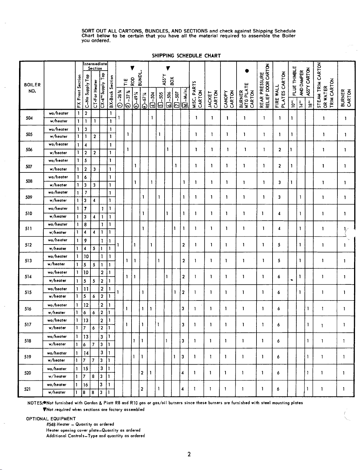
SORT OUT ALL CARTONS, BUNDLES, AND SECTIONS and check against Shipping Schedule
Chart below
you ordered.
to
be certain that you have all the material required to assemble the Boiler
SHIPPING SCHEDULE CHART
NOTES:*Not furnished with Gordon & Piatt
VNot.required when sections are factory assembled
OPTIONAL EQUIPMENT
#548
Heater - Quantity as ordered
Heater opening cover plate-Quantity as ardered
Additional Controls-Type and quantity as ordered
R8
and
R10
gas or gas/oiI burners since these burners are furnished with steel mounting plates
Page 3

IMPORTANT INFORMATION
PLEASE READ THIS PAGE CAREFULLY
1.
READ THIS MANUAL AND BURNER INSTALLATION MANUAL CAREFULLY BEFORE INSTALL
ING, OPERATING, OR SEBVICING THIS UNIT.
TO BURNHAM AND ASK FOR FORM NO.
2.
ALL BOILERS MUST BE INSTALLED IN ACCORDANCE WITH NATIONAL, STATE AND LOCAL
PLUMBING, HEATING AND ELECTRICAL C0DE.S AND THE REGULATIONS OF THE SERVING
UTILITIES.
ALL HEATING SYSTEMS SHOULD BE DESIGNED BY COMPETENT CONTRACTORS AND ONLY
3.
PERSONS KNOWLEDGEABLE IN THE LAYOUT AND INSTALLATION
SYSTEMS SHOULD ATTEMPT INSTALLATION OF ANY BOILER.
4.
THE BOILER MUST BE PROPERLY VENTED IN ACCORDANCE WITH NATIONAL FUEL GAS
CODE AND LOCAL CODES. SERIOUS PROPERTY DAMAGE
NOT PROPERLY VENTED.
5.
READ THE LITERATURE ENCLOSED BY THE MANUFACTURER WITH THE VARIOUS ACCESS-,
ORY DEVICES. THESE ACCESSORY DEVICES MUST BE INSTALLED AND USED ACCORDING TO
/
\
THE RECOMMENDATIONS OF THE MANUFACTURER.
6.
IT IS THE RESPONSIBILITY OF THE INSTALLING CONTRACTOR TO SEE THAT ALL CONTROLS
ARE CORRECTLY INSTALLED AND ARE OPERATING PROPERLY WHEN THE INSTALLATION
COMPLETED.
52003
IF
YOU DO NOT HAVE A BURNER MANUAL, WRITE
(Part
#814502).
0 F HYDRONIC HEATING
COULD RESULT IF THE BOILER
IS
IS
7.
FOR OPTIMUM PERFORMANCE FROM THIS UNIT SEIRVECE AS SPE(C1FIED IN SECTION V OF
THIS MANUAL.
8.
IN ALL CASES, CLEARANCES BETWEEN BOILER AND/OR SMOKE PIPE SURFACES AND COMBUSTIBLE MATERIALS MUST COMPLY WITH NATIONAL FUEL GAS CODE ANSI
DATED
ALL FLAMMABLE DEBRIS, RAGS, PAPER, WOOD SCRAPS, ETC., SHOULD BE KEPT CLEAR OF
9.
THE BOILER AT ALL TIMES. KEEP THE BOILER AREA CLEAN AND FREE OF FIRE HAZARDS.
10.
PROBE AND FLOAT TYPE LOW WATER CUTOFF DEVICES REQUIRE ANNUAL INSPBCTION AND
MAINTENANCE. REFER TO SECTION V ITEM
ING INSTRUCTIONS.
HIGH WATER TEMPERATURES INCREASE THE RISK OF BURNS OR SCALDING INJURY. INSTALL
AUTOM-4TIC MIXING VALVE AT THE TANKLESS HEATER OUTLET TO AVOID EXCESSIVELY HOT
WATER AT THE FIXWRES AS SHOWN IN FIGURE
1988
OR CURRENT EDITION AND, FOR OIL, NFPA
@
26.
211.
FOR STEP BY STEP INSPECTION AND CLEAN-
2223.1
(NFPA
54)
AN
Page 4
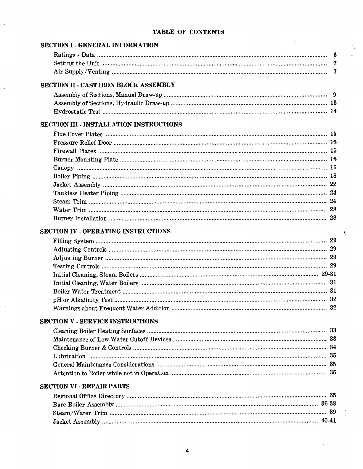
TABLE OF CONTENTS
.
SECTION I
Ratings . Data
Setting the Unit
Air Supply/Venting
.SECTION TI . CAST IRON BLOCK ASSEMBLY
GENERAL INFORMATION
................................................................................................................................................
.............................................................................................................................................
....................................................................................................................................
6
7
7
..
Assembly of Sections, Manual Draw-up
Assembly of Sections. Hydraulic Draw-up
Hydrostatic Test
SECTION I11 . INSTALLATION INSTRIJCTIONS
Flue Cover Plates
Pressure Relief Door
Firewall Plates
Burner Mounting Plate
Canopy
Boiler Piping
Jacket Assembly
Tankless Heater Piping
Steam Trim
Water Trim
Burner Installation
SECTION IV . OPERATING INSTRUCTIONS
Filling System
Adjusting Controls
Adjusting Burner
Testing Controls
Initial Cleaning, Steam Boilers
Initial Cleaning, Water Boilers
Boiler Water Treatment
pH or Alkalinity Test
Warnings about Frequent Water Addition
............................................................................................................................................................
............................................................................................................................................
.........................................................................................................................................
.....................................................................................................................................
...............................................................................................................................................
.................................................................................................................................
...............................................................................................................................................
............................................................................................................................................
.................................................................................................................................
....................................................................................................................................................
....................................................................................................................................................
......................................................................................................................................
................................................................................................................................................
........................................................................................................................................
..........................................................................................................................................
............................................................................................................................................
................................................................................................................
.....................................................................................................................
... ; ...........................................................................................................................
....................................................................................................................................
.....................................................................................................
.................................................................................................
................................................................................................
9
13
14
15
15
15
15
16
18
22
24
24
28
28
29
29
29
29
29-31
31
31
32
32
SECTION V . SERVICE INSTRUCTIONS
Cleaning Boiler Heating Surfaces
Maintenance of Low Water Cutoff Devices
Checking Burner & Controls
Lubrication
General Maintenance Considerations
Attention to Boiler while not in Operation
.SECTION VI . REPAIR PARTS
Regional Office Directory
Bare Boiler Assembly
Steam/Water Trim
Jacket Assembly
....................................................................................................................................................
.............................................................................................................................
..............................................................................................................................
......................................................................................................................................
......................................................................................................................................
................................................................................................................
.........................................................................................................................
33
.............................................................................................
.........................................................................................................
..................................................................................................
33
34
35
35
35
35
36-38
3.
40-41
9
.
Page 5
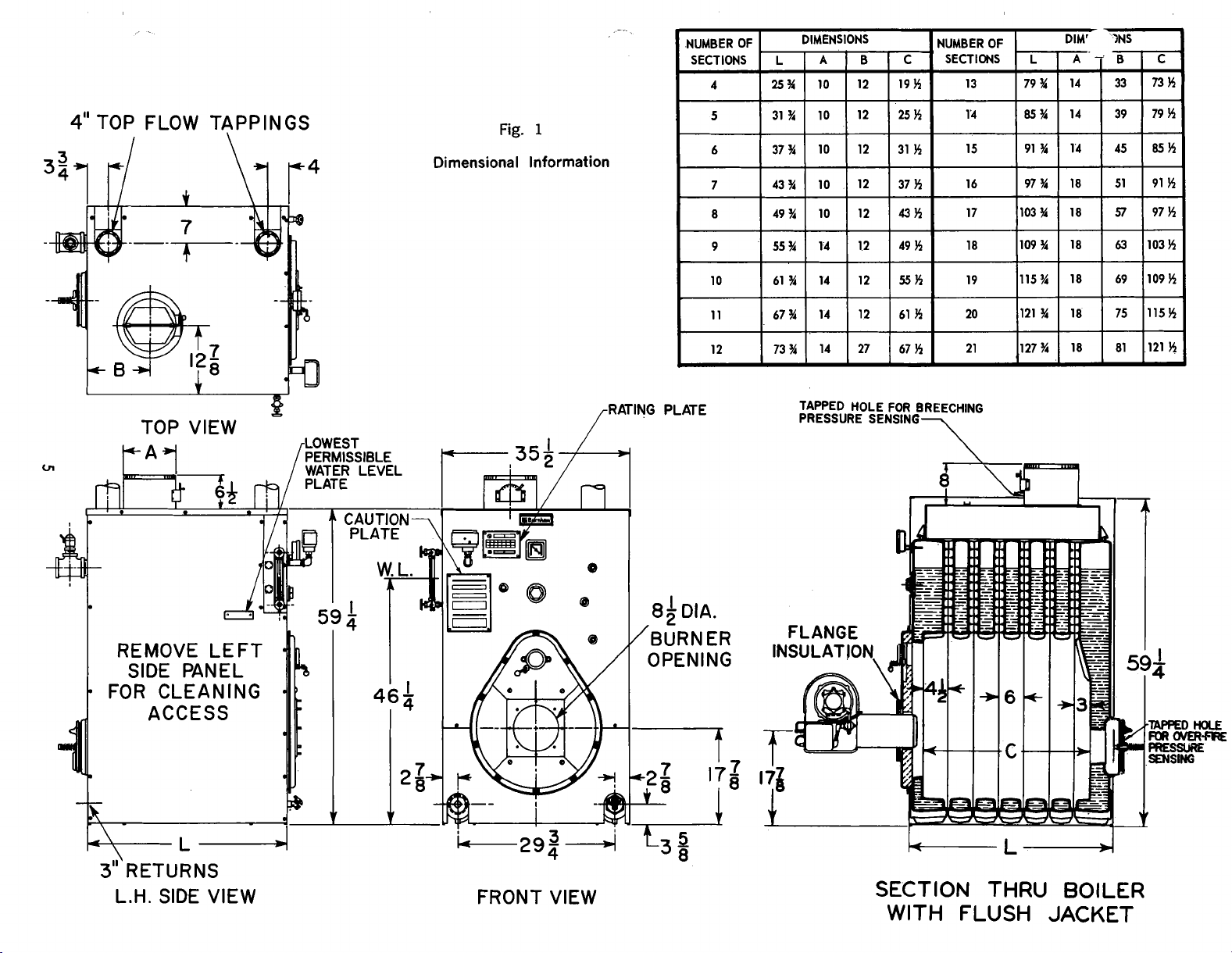
4"
TOP FLOW TAPPINGS
Fig.
1
Dimensional Information
TOP VlEW
REMOVE LEFT
SlDE PANEL
FOR CLEANING
ACCESS
4
YL
3
RETURNS
L.H.
SlDE VlEW
$2
WATER LEVEL
I
L29:
FRONT VlEW
4
8h
DIA.
'BURNER
OPENING
TAPPED HOLE FOR BREECHING
PRESSURE SENSING
SECTION THRU BOILER
WITH FLUSH
JACKET
Page 6
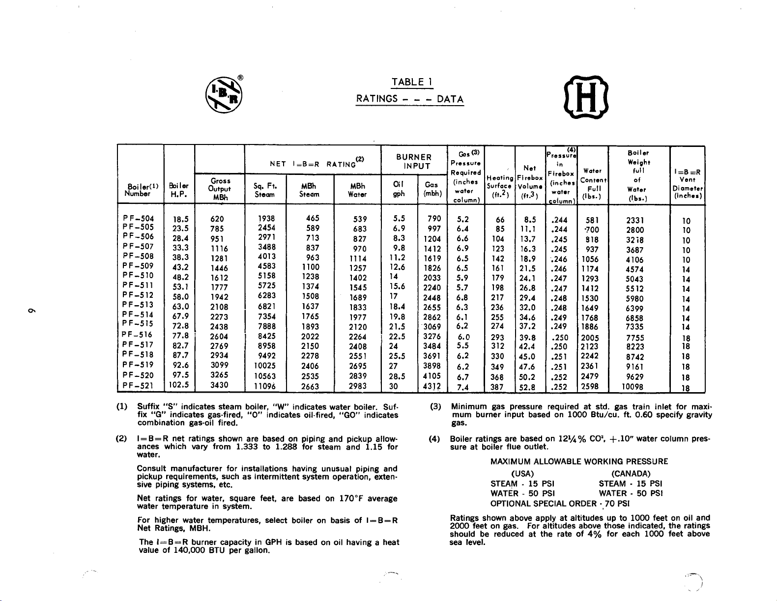
TABLE
RATINGS
-
- -
1
DATA
NET I=B=R RATING
Boiler(1)
Number
5iler
H.P.
Gross
output
-
MBh
sq.
Steam
Ft.
Bh
M
Steam
Water
620
785
1
95
16
11
1281
1446
1612
1777
1942
2108
2273
2438
2604
2769
2934
3099
3265
3430
Suffix "S" indicates steam boiler,
(1)
(2)
"G"
fix
combination gas-oil fired.
I=B=R net ratings shown are based on piping and pickup allowances which vary from
water.
Consult manufacturer for installations having unusual piping and
pickup requirements, such as intermittent system operation, extensive piping systems, etc.
Net ratings for water, square feet, are based on
water temperature in system.
For higher water temperatures, select boiler on basis of
Net Ratings, MBH.
The I=B=R burner capacity in GPH is based on oil having a heat
value of
indicates gas-fired,
1.333
140,000
BTU per gallon.
"W
"0"
to
indicates water boiler. Suf-
indicates oil-fired, "GO" indicates
1.288
for steam and
170°F
(2)
MBh
1.15
for
average
I
=
B= R
BURNER
INPUT
-
Gas
(mbh)
-
1204
1412
1619
I826
2033
2240
2448
2655
2862
3069
3276
3484
3691
3898
4105
4312
-
-
Boil
Gas
(3)
'ressure
?equired
(inches
watet
column)
790
5.2
6.4
997
6.6
6.9
6.5
6.5
5.9
5.7
6.8
6.3
6.1
6.2
6.0
5.5
6.2
6.2
6.7
7.4
-
Minimum gas pressure required at std. gas train inlet for maxi-
(3)
mum burner input based on
gas.
Boiler ratings are based on
(4)
sure at boiler flue outlet.
MAXIMUM ALLOWABLE WORKING PRESSURE
STEAM
WATER
OPTIONAL SPECIAL ORDER
Ratings shown above apply at altitudes up to
2000
feet on gas. For altitudes above those indicated, the ratings
should be reduced at the rate of
sea level.
Net
:irebo:
4olum1
(ft.3
8.5
11.1
13.7
16.3
18.9
21.5
24.1
26.8
29.4
32.0
34.6
37.2
39.8
42.4
45.0
47.6
50.2
52.8
-
(USA)
-
-
Water
Eonten
)
(I
-
Full
br.)
58
-700
918
937
1056
1174
1293
1412
1530
1649
I768
1886
2005
2
123
2242
236
2479
2598
1000
Btu/cu. ft.
121/q%
15
PSI STEAM
50
PSI
COZ,
4%
1
1
+.lo
(CANADA)
WATER
-
70
for each
er
Weight
full
of
Water
(1,bs.)
233
1
2800
32i8
3687
4106
4574
5043
5512
5980
6399
6858
7335
7755
8223
8742
9161
9629
10098
0.60
specify gravity
water column pres-
-
15
PSI
-
50
PSI
PSI
1000
feet on oil and
1000
=B
=R
Vent
liarnetel
inehes]
feet above
Page 7

SECTION
I
-
GENERAL INFORMATION
(
CONTINUED
)
@
INSPECT SHIPMENT carefully for any signs
.
damage.
4.
ALL EQUIPMENT is carefully manufactured, inspect-
ed and packed. Our responsibility ceases upon delivery
of crated Boiler to the carrier in good condition.
B. ANY CLAIM'S for damage or shortage in shipment
must be filed immediately against the carrier by the
consignee. No claims for variances from, or shortage
in orders, will be allowed by the manufacturer unless
presented within sixty (60) days after receipt of
goods.
@
BOILER INSTALLATION - Must conform to the
authority having jurisdiction, or in the absence of such
-
:
-
1967 (Re-
Above or Top
-
6 Inches
requirements to
USA
-
Installation of oil burning equipment, AN'SIINFPA 31.
CANADA
Oil Fired Steam and Hot Water Boilers for 'Commercial
and Industrial use, ,CSA Standard B140.7.2
affirmed 1991)
MINIMUM INSTALLATION CLEARANCES TO COMBUSTIBLE MATERIAL:
-
Front
Sides
Rear
24 Inches
-
6 Inches Vent Connector Pipe - 18 Inches
-
6 Inches
of
IF BOILER
A
WATXR COWDIIIOR mIST8. A BOILER WUHDATIOR
ROW
PICOR IS WEAK
OR
UHEVEW
Fig.
OR
IF
2
VOTE:
Listed clearances comply with American National Standard ANSIINFPA 31, Installation of oil ,burning
equipment.
Listed clearances can not be reduced for alcove or
closet installations.
For reduced clearances to combustible material, protection must be provided as described in the above
31
ANSIINFPA
A. SERVICE 'CLEARANCE
er room so as to provide ease of venting and adequate
clearance for maintenance, serviceability, and installation of piping. Allow a minimum clearance of
at front and back of boiler for burner service and access to pressure relief
on each side of the unit for cleaning of flues and for
tankless water heater installation. 'Refer
for boiler dimensional data.
B. PROVIDE ADEQUATE FOUNDATION for the unit.
ON CARPETING. 'Boiler is suitable for installation
on combustible floors.
2. Floor construction should have adequate load bearing characteristics to bear the weight of the boiler
filled with water (see Table 1). A boiler foundation
similar to the one shown in Figure 2 is recommended if the boiler room floor is weak or uneven or if
a water condition exists.
standard.
-
Locate the unit in the boil-
door/flame observation port and
to
Figure
3
feet
1
TYPICAL ARRANGEMENT
FOR STUB VENT
Fig.
3
Page 8
@
PROVIDE AIR SUPPLY AND VENTILATION to
accomodate proper combustion.
A permanent opening or duct should be provided so that
4,000
the boiler input will not exceed
area.
@
CHIMNEY OR VENT
The PF-5 is designed for forced draft firing and may be
a
used with
conventional natural draft stack or a stub
Btuhlin of free
vent (see Figure
Draft controls are not normally required, although they
may be used on installations where a natural draft stack
is used or on multiple boiler installations with a common
stack. The boiler is provided with a breeching
which should be adjusted to maintain a slightly positidt
pressure in the vent connector box (up to
ing burner operation.
3).
See Table I for the proper vent size.
0.1"
W.C.) dur-
dampey-
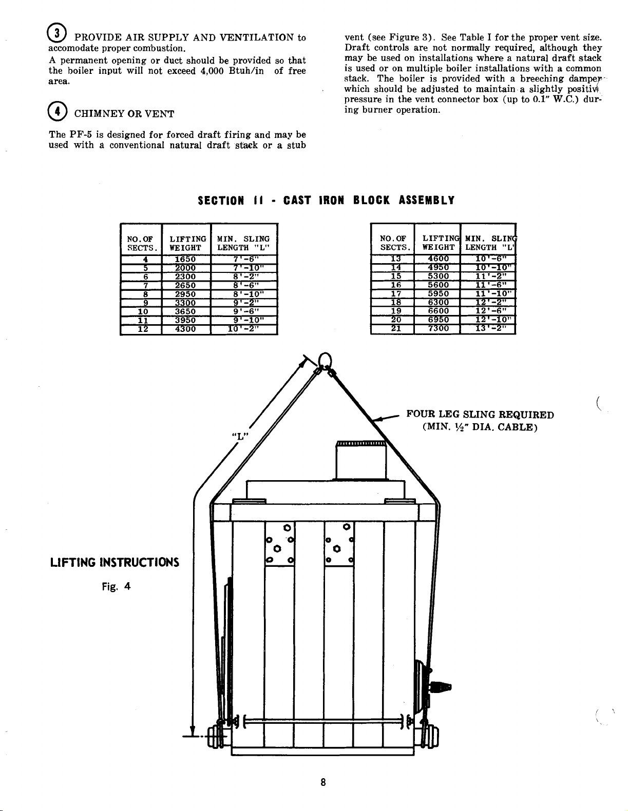
SECTION
II
-
CAST IRON BLOCK ASSEMBLY
FOUR LEG SLING
('MIN.
34"
DIA.
REQUIRED
CABLE)
LIFTING INSTRUCTIONS
Fig.
4
Page 9
@
FACTORY ASSEMBLED SECTIONS - The assemblage should be set in the proper location as outlined in
9ection
Figure
The tie-rod nuts should then be loosened until finger
tight. Now proceed to part
STATIC TEST".
@
sembly procedure outlined on the following pages.
A. Assembly of Sections (Manual Draw-Up)
DRAULIC DRAW-UP EQUIPMENT, NEVER
B'LE MORE THAN ONE SECTION AT A TIME.
(
I.
Lifting arrangement and weights are given in
4.
@
of this section "HYDRO-
FIELD ASSEMBLED SECTIONS - Follow the as-
WHEN ASSEMBLING 'SECTION'S WITHOUT HY-
ASSEM-
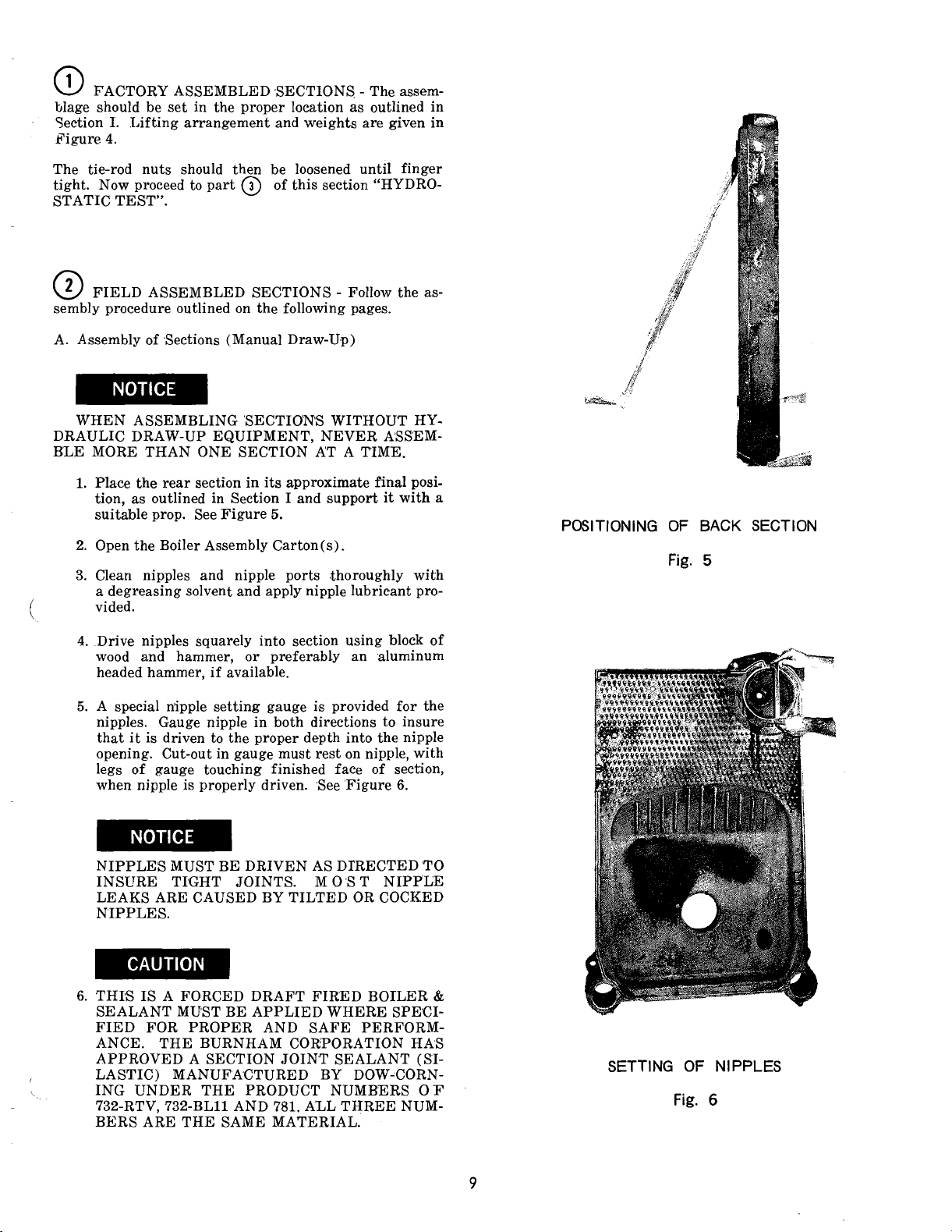
1.
Place the rear section in its approximate final position, as outlined in Section I and support it with a
suitable prop. See Figure
2.
Open the Boiler Assembly Carton(s)
3. Clean nipples and nipple ports ,thoroughly with
a degreasing solvent and apply nipple lubricant provided.
5.
.
POSITIONING OF BACK SECTION
Fig.
5
4.
Drive nipples squarely into section using block of
wood and hammer, or preferably an aluminum
headed hammer, if available.
5.
A special n'ipple setting gauge is provided for the
nipples. Gauge nipple in both directions to insure
that it is driven to the proper depth into the nipple
opening. Cut-out in gauge must rest on nipple, with
legs of gauge touching finished face of section,
when nipple is properly driven. See 'Figure
NIPPLE'S MUST BE DRIVEN AS DTRECTED'TO
INSURE TXHT JOINTS. M
LEAKS ARE CAUSED BY TILTED OR COCKED
NIPPLES.
6.
THIS IS A FORCED DRAFT FIRED BOILER
SEALANT MUST BE APPLIED WHERE SPECIFIED FOR PROPER AND SAFE PERFORMANCE. THE BURNHAM CORPORATION HAS
APPROVED A SECTION JOINT SEALANT
LASTIC) MANUFACTURED BY DOW-CORN-
\
ING UNDER THE PRODUCT NUMBERS OF
732-RTV, 732-BLll AND 781. ALL THREE NUMBERS ARE THE SAME MATERIAL.
0
B T NIPP'LE
6.
&
(SI-
SETTING OF NIPPLES
Fig.
6
Page 10

The grooves in the ground joint along the edge of
the section should be cleaned with a wire brush.
a
Then using
apply
'/a"
cartridge of sealant in a caulking gun,
bead of Silastic to one side of each joint.
to be mated. Touch up any missed spots before
draw-up. Touch-up after draw-up has no value. See
Figure
7.
SECTIONS MUST BE DRAWN-UP TIGHT
WTTHIN FOUR HOURS OF TWE TIME WHEN
STLASTIC I'S FIRST APPLIED. 'SILASTIC
CURES IN FOUR HOURS AND WILL NOT
FLOW INTO SEAL GROOVES AFTER FOUR
HOURS FROM APPLICATION, REGARDLESS
OF THE PRESSURE APPLI'ED.
7.
From arrangement of sections chart (see Figure
8)
select next section according to code letters on
section.
SECTIONS MUST BE ASSEMBLED IN PROPER
ORDER.
Clean .nipple ports and place section on nipples in
rear section. 'To facilitate assembly, it is advisable
to enter the upper nipple first in its port, then enter
the lower nipples in their respective ports.
Drive section in place with a heavy block of wood,
striking blows as squarely as
%"
Insert the three
draw-up rods through the nipple
possible over nipples.
ports in the intermediate section extending them
through the tapped holes in the rear section.
Place a 12" lg. steel channel on each end of the
upper draw-up rod and an
8%" lg. steel channel on
each end of the lower draw-up rods along with nuts
and washers. These items are all located in the
9
Draw-Up Kit. See Figures
and 10.
Be sure to apply the sealant to the groove in the
ground joints between adjacent sections as the boiler operates with a positive pressure ,in the fireboxf
and products of combustion will escape between
sections unless the sections are properly sealed. The
sealant should be applied before each section is phced on the assemblage.
I
AVOID DAMAGE TO THE DRAW ROD
THREADS WHILE DRAWING UP SECTIONS.
APPLY OIL OR GREASE FREELY 'TO TIE ROD
THREADS WHILE ASSEMBLING SECTIONS
TO PREVENT STRIPPING OF THREADS ON
ROD.
DRAW UP SECTION SLOWLY AND EVENLY,
tightening each draw-up rod a little at a time so
that sections are equally spaced, starting with
lower draw-up rods.
KEEP NIPPLES ALIGNED WITH NIPPLE
PORTS. If necessary, tap nipples lightly with a
blunt tool or rod to keep nipples from cocking while
sections are being drawn up. DO NOT DRAW UP
SECTION WHEN
NIPP-LES ARE COCKED. Continue tightening draw-up rods equally, periodically
bumping the section with the heavy block of wood
to relieve tensi'on on the draw-up rods, until sections meet iron-to-iron on the ground surfaces.
CONTINUE ASSEMBLING SECTIONS IN
THEIR RESPECTIVE ORDER. Be certain that
all sections are drawn up iron-to-iron at all three
nipple ports.
APPLICATION
Fig.
OF
7
SEALANT
Page 11
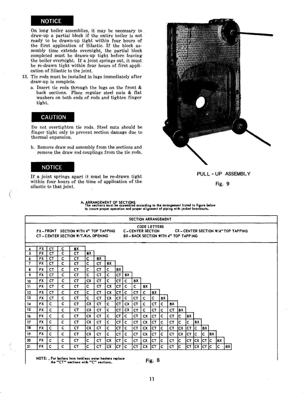
On long boiler assemblies, it may be necessary to
draw-up a partial block if the entire boiler is not
ready to be drawn-up tight within four hours of
the first application of Silastic. If the block assembly time extends overnight, the partial block
completed must be drawn-up tight before leaving
the boiler overnight. If a joint springs out, it must
be re-drawn tight within four hours of first application of Silastic to the joint.
13.
Tie rods must be installed in lugs immediately after
draw-up is complete.
a. Insert tie rods through the lugs on the front
back sections. Place regular steel nuts & flat
washers on both ends of rods and tighten finger
tight.
Do not overtighten tie rods. Steel nuts should be
finger tight only to prevent section damage due to
thermal expansion.
b. Remove draw rod assembly from the sections and
remove the draw rod couplings from the tie rods.
&
i.
If
a
joint springs apart it must be re-drawn tight
within four hours of the time of application of the
silastic to that joint.
A
RRANGEMENT OF SECTION3
?he sections must be assemble according to the arronpemont listed in figure blow
to insure proper operation and proper alignment of pipiG with jacket knockouts.
--
FX-FRONT SECTION WITH 4'* TOP TAPPING C-CENTER SECTION CX
CT
-
r
CENTER SECTION W/T.W.H. OPENING
--
SECTION ARRANGEMENT
CODE LETTERS
BX - BACK SECTION WITH
-
CENTER SECTION W/4"TOP TAPPING
4"
TOP TAPP ING
PULL - UP ASSEMBLY
Fig.
9
NOTE: . For boilers less tmklns water hooters replace
I
the
"CT"
~utions with p'~s* sections..
Fig.
8
Page 12

CHANNEL BLOCK IN POSITION
Fig.
10
SECTION ASSEMBLEDGE
Fig.
11
Page 13
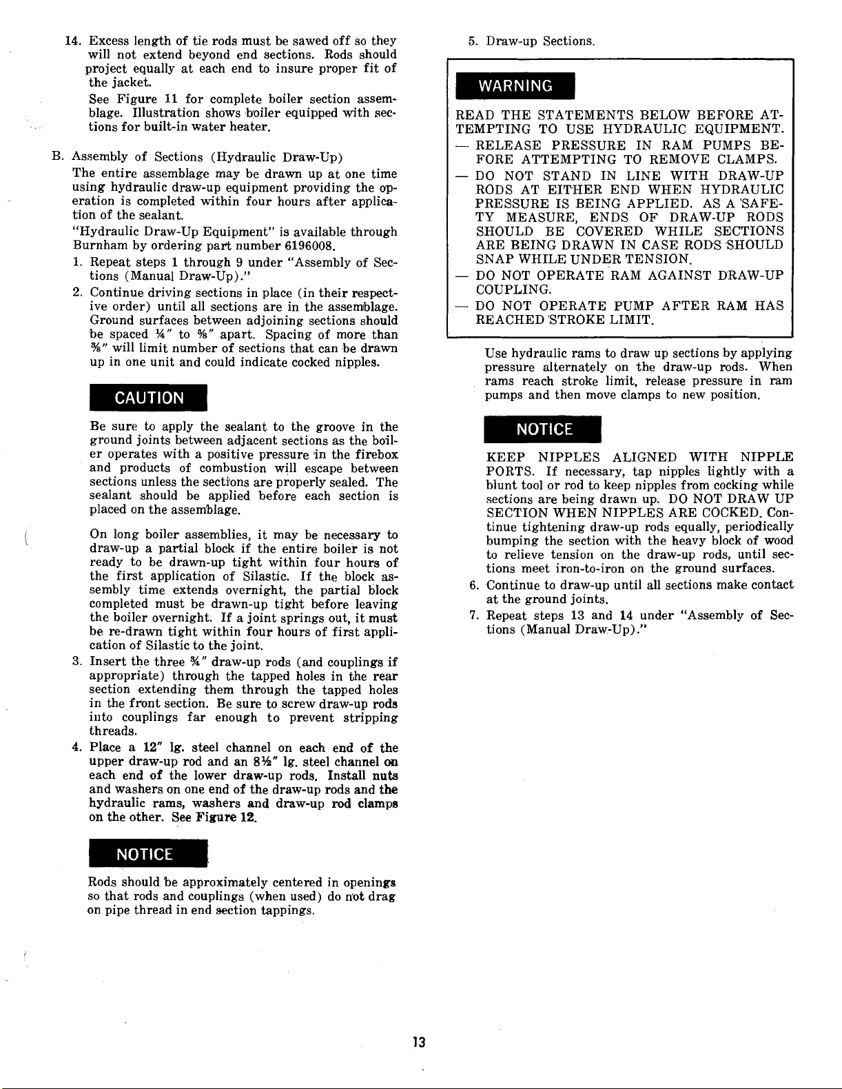
14.
Excess length of tie rods must be sawed off so they
will not extend beyond end sections. Rods should
project equally
the jacket.
See Figure
blage. Illustration shows boiler equipped with sections for built-in water heater.
B. Assembly of Sections (Hydraulic Draw-Up)
The entire assemblage may be drawn up at one time
using hydraulic draw-up equipment providing the
eration is completed within four hours after application of the sealant.
"Hydraulic Draw-Up Equipment" is available through
Burnham by ordering part number
1.
Repeat steps 1 through 9 under "Assembly of Sec-
tions (Manual Draw-Up)
2.
Continue driving sections in place (in their respective order) until all sections are in the assemblage.
Ground surfaces between adjoining sections should
be spaced
%"
will limit number of sections that can be drawn
up in one unit and could indicate cocked nipples.
Be sure to apply the sealant to the groove in the
ground joints between adjacent sections as the boiler operates with a positive pressure
and products of combustion will escape between
sections unless the secti'ons are properly sealed. The
sealant should be applied before each section is
placed on the assemblage.
On long boiler assemblies, it may be necessary to
draw-up a partial block if the entire boiler is not
ready to be drawn-up tight within four hours of
the first application of Silastic.
sembly time extends overnight, the partial block
completed must be drawn-up tight before leaving
the boiler overnight. If a joint springs out, it must
be re-drawn tight within four hours of first application of Silastic to the joint.
3.
Insert the three
appropriate) through the tapped holes in the rear
section extending them through the tapped holes
in the front section. Be sure to screw draw-up rods
illto couplings far enough to prevent stripping
threads.
4.
Place a
upper draw-up rod and an
each end of the lower draw-up rods.
and washers on one end of the draw-up rods and
hydraulic rams, washers
on the other. See Figure
at
each end to insure proper fit of
11
for complete boiler section assem-
6196008.
."
%"
to
%"
apart.
%"
draw-up rods (and couplings if
12"
lg. steel channel on each end of the
Spacing of more than
'in the firebox
If the block as-
8%"
lg. steel channel
Install
and
draw-up
rod
12.
op-
on
nuts
the
elampe
5.
Draw-up Sections.
READ THE STATEMENTS BELOW BEFORE ATTEMPTING TO USE HYDRAULIC EQUIPMENT.
-
RELEASE PRESSURE IN RAM PUMPS BEFORE ATTEMPTING TO REMOVE CLAMPS.
-
DO NOT STAND IN LINE WITH DRAW-UP
RODS AT EITHER END WHEN HYDRAULIC
PRESSURE IS BEING APPLIED.
TY MEASURE, ENDS OF DRAW-UP RODS
SHOULD BE COVERED WHILE SECTIONS
ARE BEING DRAWN IN CASE RODS SHOULD
SNAP WHILE UNDER TENSION.
-
DO NOT OPERATE RAM AGAINST DRAW-UP
COUPLING.
-
DO NOT OPERATE PUMP AFTER RAM HAS
REACHED 'STROKE LIMIT.
Use hydraulic rams to draw up sections by applying
pressure alternately on the draw-up rods. When
rams reach stroke limit, release pressure in ram
pumps and then move clamps to new position.
KEEP NIPPLES ALIGNED WITH NIPPLE
PORTS. If necessary, tap nipples tightly with a
blunt tool or rod to keep nipples from cocking while
sections are being
SECTION WHEN NIPPLES ARE COCKED. Continue tightening draw-up rods equally, periodically
bumping the section with the heavy block of wood
to relieve tension .on the draw-up rods, until sections meet iron-to-iron on the ground surfaces.
6.
.Continue to draw-up until all sections make contact
at the ground joints.
7.
Repeat steps
tions (Manual Draw-Up)
drawn up. DO NOT DRAW UP
13
and
14
under "Assembly of Sec-
."
AS A 'SAFE-
Rods should be approximately centered in openings
so that rods and couplings (when used) do njot drag
on pipe thread in end section tappings.
Page 14
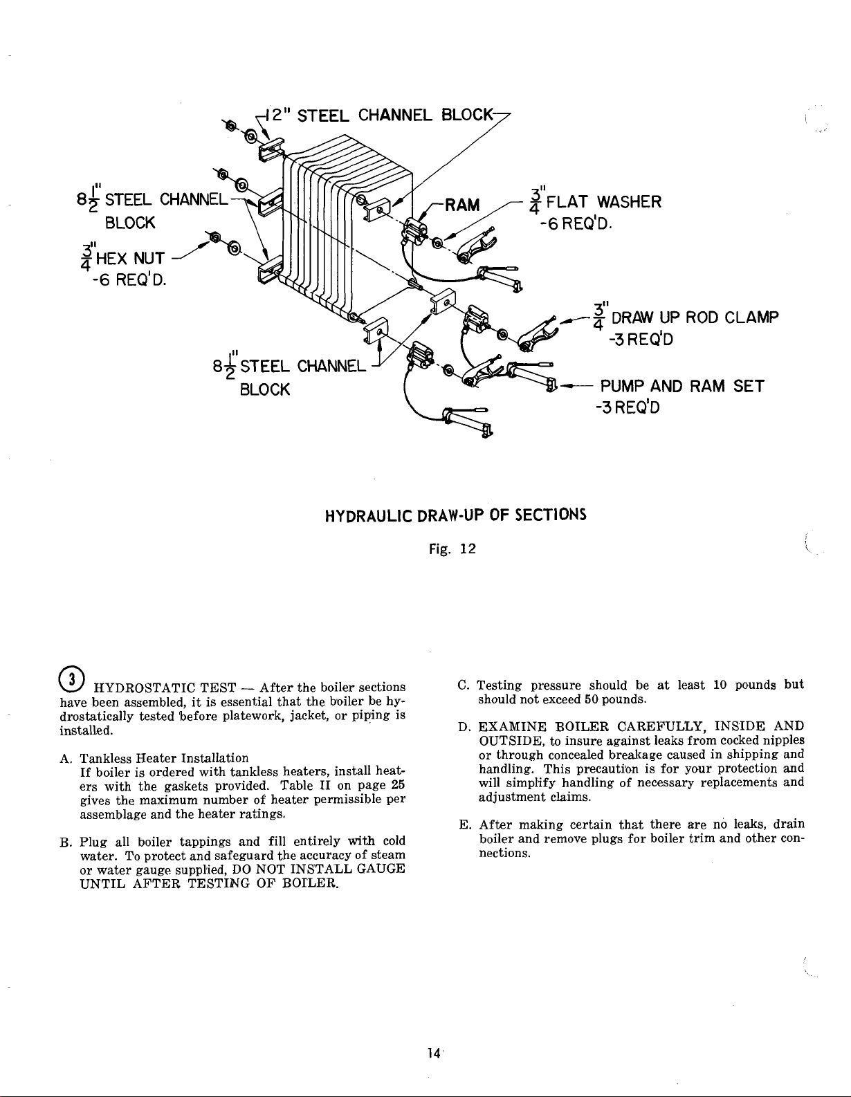
:L
CHANNEL BLOCK
7
BLOCK
HYDRAULIC DRAW-UP
Fig.
@
HYDROSTATIC TEST - After the boiler sections
have been assembled, it is essential that the boiler be hydrostatically tested before platework, jacket, or piping is
installed. D.
Tankless Heater Installation
If boiler is ordered with tankless heaters, install heaters with the gaskets provided. Table
gives the maximum number of heater permissible per
assemblage and the heater ratings.
Plug all boiler tappings and fill entirely
water. To protect and safeguard the accuracy of steam
or water gauge supplied, DO NOT INSTALL GAUGE
UNTIL AFTER TESTING OF BOILER.
I1
on page
with
25
cold
C. Testing pressure should be
E.
3''
--q
-
-
OF
SECTIONS
12
should not exceed
EXAMINE BOILER CAREFULLY, INSIDE AND
OUTSIDE, to insure against leaks from cocked nipples
or through concealed breakage caused in shipping and
handling. This precauti'on is for your protection and
will simplify handling of necessary replacements and
adjustment claims.
After making certain that there
boiler and remove plugs for boiler trim and other con-
nections.
DRAW UP
-3
REQ'D
PUMP AND
PUMP AND
50
pounds.
ROD CLAMP
RAM
at
least
are no leaks, drain
SET
10
pounds but
Page 15

SECTION
a
INSTALL FLUE COVER PLATES over cleanout
openings 'on left side of boiler as shown in Figure 13.
A. Locate the cover plates, carriage bolts, nuts and wash-
ers in the miscellaneous parts carton.
11
I
-
INSTALLATION INSTRUCTIONS
CLEANOUT COVER
7
r
COVER GASKET
B. Attach the carriage bolts to the top and bottom of the
flue openings with washers and hex nuts to provide a
fixed stud.
C.
Install flue cover plates & gaskets over studs and secure
with washers and nuts.
@
MOUNT PRESSURE RELIEF DOOR
A. Apply a
inside face of the pressure relief door.
B. Mount the pressure relief door onto the rear section
(with the word "Top" in the upright position) using
the (4) -&"-18 x
aneous parts carton.
side of the center sections. The plates should be 'installed
toward the front of the boiler.
IMPORTANT
BUSTION CHAMB.ER.
%"
bead of Silastic along the groove on the
1"
cap screws located in the miscell-
Install the refractory firewall plates on the right
See Figure 14.
-
THIS BOILER REQUIRE'S NO COM-
INSULATION
CLEANOUT NU
AND WASHER
TOP VIEW
CLEANOUT COVER ASSEMBLY
Fig.
13
@
MOUNT BURNER MOUNTING PLATE
A. Cast iron burner mounting plate. Install (10)
long studs with the short length of threads into the
boiler front section. Apply a bead of sealant around
the periphery of the cast iron burner plate and secure
to front section with
B. Cast iron burner mounting plate with adapter plate
(R-6 Burner Only). The adapter plate is furnished by
Gordon-Piatt and
the cast iron burner mounting plate as stated in (A)
above. Mount the adapter plate to the mounting plate
(8)
%"
with
and gasket provided. The R6 burner can now be secured to (4) studs on adapter plate using
nuts and washers.
x
h''
nuts and washers.
'is shipped with the burner. Mount
1%" cap screws, %-I6 hex nuts, washers
(4)
15"
x
2
%-I6 hex
FIREWALL PLATES
Fig.
14
Page 16

Steel burner mounting plate (see item D below for R-8
&
R-10 mounting plate instructions). With the use of
silastic, secure the rope gasket to the front section just
inside the rib to which the burner plate seats. Using
the (10) &"-I8 x
mount burner plate to front section. With bolts provided mount burner to steel ,burner plate, see Figure
15
for view showing steel burner plate installed.
D. Steel burner mounting plate with mounting lugs (R-8
and R-10 Burner Only). Mount .the burner mounting
plate as stated in (c) above. Locate the (6)
ing lugs in the mounting plate carton. Attach the lugs
to the weld studs on the burner mounting plate with
the
%"
stalled, orient the lugs towards the center of the opening such that they hold the burner flange in place.
@
Attach the canopy brackets to the ends of the canopy
wit& sheet metal screws. Two piece canopies should
be joined together using the #10 x
screws provided.
hex nuts & washers.
Canopy Assembly
1"
long hex head machine screws,
%"
When the burner is in-
%"
sheet metal
mount-
Along the groove provided on top of the sections and
across the top of the end sections, apply 2" wide strips
of cerafelt and lap joint at corners. 'See Fig. 16.
Place the canopy on the sections with the word
"FRONT" positioned over the front section.
Secure the canopy to the end sections by extending the
&"
x 11%" carri.age bolts from the end sections to the
canopy brackets. Attach the canopy channels to the
canopy and intermediate sections with the appropriate
J-bolts.
Check the seal between the canopy and the sections.
Assemble the flue thimble to the top of the canopy
with the bracket toward the front of the boiler using
#10 x
%"
screws.
Figure 17 shows the canopy assembled to the sections
with the flue
Place canopy insulation over canopy foil side up, fold
down sides and secure with wire.
@
Inspect Seal
A. After the platework is in place, a visual inspection
should be made of all sealed joints and repairs made
if necessary. A darkened boiler room with a light
source in the combustion space and canopy will aid
this inspection.
thim'ble in place.
Fig.
15
@
BOILER PI'PING
CONNECT SUPPLY AND RETURN PIPING
HEATING SYSTEM.
MUM PIPING REQUIREMENTS AND ARRANGEMENTS BE COMPLIED WITH IN ORDER TO INSURE
MAXIMUM RELIABILITY PERFORMANCE.
A. CLEARANCES
have clearances of at least
construction.
B. W5th STEAM HEATING, see Figure 20, consult I=B
=R Installation and Piping Guide No. 200.
BE GIVEN TO THE CONSTRUCTION OF THE
HARTFORD LOOP ON STEAM BOILERS. FIGURE
22 ILLUSTRATES THE RIGHT AND WRONG WAY
TO CONSTRUCT THE STEAM HEADER.
With forced circulation HOT WATER HEATING,
see Figure 21, consult
Guide No. 200.
1.
If this boiler is used in connection with refrigeration systems, the boiler must be installed so that
the chilled medium is piped in parallel with the(
heating boiler using appropriate valves to prevent\
the chilled medium from entering the boiler, see
Figure 18. Also, consult
Piping Guides.
IT IS IMPORTANT THAT THE MINI-
-
All steam and hot water pipes shall
%"
from all combustible
PARTICULAR ATTENTION SHOULD
I=B=R Installation and Piping
I=B=R Installation and
TO\
Page 17

GROOVES AT TOP OF SECTION
FOR CANOPY SEALANT
Fig.
16
THIMBLE & CANOPY ASSEMBLY SECURED & SEALED TO SECTIONS
Page 18

If this boiler ,is connected to heating coils located
in air handling units where they may be exposed to
refrigerated air, the boiler piping must be equipped
with flow control valves to prevent gravity circulation of boiler water during the operation of the
cooling system.
If the boiler will be operated where low boiler water
temperatures may be encountered (i.e. converted
gravity circulation systems, etc.) the use of a boiler
water bypass is recommended to maintain optimum
operation.
Remove the circulator and install a pipe tee between 'the circulator and boiler return along with a
second tee in the supply piping as shown in Figure
19.
The bypass should be the same size as the supply and return lines with valves located in the bypass and supply outlet as illustrated in Figure
order to regulate water flow for main-tenance of
higher boiler water temperature.
Set the by-pass and boiler supply valves to a half
throttle position to start.
system water temperature is at a normal operating
range.
Adjust the salves to provide 180" to 200°F supply
water temperature. Opening the boiler supply valve
will raise the system temperature, while opening
the by-pass valve will lower the system supply temperature.
Operate boiler until the
19
OXYGEN CORROSION
Oxygen contamination of the boiler water will cause
corrosion of the iron and steel boiler components, which
can lead to failure. As such, any system must be designed
to prevent oxygen absorption in the first place or prevent
it from reaching the boiler. Problems caused by oxygen
contamination of boiler water are not covered by Buw-
ham's standard warranty.
There are many possible causes of oxygen contamination such as
1.
Addition of excessive make-up water as a result of
system leaks.
2.
Absorption through open tanks and fittings.
3.
Oxygen permeable materials in the distribution system.
In order to insure long product life, oxygen sources
should be eliminated. This can be accomplished by taking
the following measures
Repairing system leaks to eliminate the need for
addition of make-up water.
Eliminating open tanks from the system.
Eliminating and/or repairing fittings which allow
oxygen absorption.
Use of non-permeable materials in the .distribution
system.
Isolating the boiler from the system water by installing a heat exchanger.
:
:
:
'
A hot water boiler installed above radiation level
must be provided with a low water cutoff device
as part of the installation.
WUT - OFF
VALVE
HEATING
BOILER
[AIR CUSHION TANK
CIRCULATOR
I
I
RECOMMENDED PIPING FOR COMBINATION
&
HEATING
COOLING (REFRIGERATION) SYSTEMS
WATER BOILERS
Fig.
18
RETUN MAIN
FROM
COYDINED
nEAT1NG
COOLING
SYSTEM
a
BYPASS
RECWENDED
VALVE
BY
TO SYSTEM
THERMOMETER
-
PASS PI PING - WATER BOILERS
Fig.
19
COCK
..
Page 19

I
BOILER
1
PIPE SIZE ( INCHES)
IR'si~~z'NGI
PF-
504
PF-
AND
514
THRU PF-
PF
-
505
517
PF
-
506
THRU PF
-
509
FRONT EQUALIZER
HARTFORD
LOOP
PF
PF
RETURN
-
518
-
510
THRU PF - 513
THRU PF
-
521
OPTIONAL
SECONDARY
TO
4"
2"
PF-504(1)4
PF-505
PF
-
PFPF-510
508
509
(1)
4
(21
4
(2)
4
(314
2
2
'I2
2
2
b2
2Il2
4
4
6
6
8
21/2
29,
2
2
2
b2
----
----
- - -
42;
4eh
24$+
-
-
-
-
-
*
Secondary Supply Connections illustrated ,in dotted lines are to be used
only in addition to supply~connections shown in solid lines, not in lieu of.
MINIMUM PIPING REQUIREMENTS STEAM BOILERS
Fig.
20
Page 20

SUPPLY
SUPPLY
FRONT
SUPPLY
I
PF - 504 THRU PF - 507 PF - 508 THRU PF - 513
3"
RETURN
HEADER
(INCHES)
I
RETURN
PF
-
514
THRU PF
MINIMUM PIPING REQUIREMENTS WATER BOILERS
-
521
HEADER
Page 21

HORIZONTAL
ON RISERS
'.*
SECONDARY
SUPPLY
-USE REDUCING ELBOW
OR ATTACH EQUALIZER
TO
BOTTOM OF HEADER
'YQUALIZER
GATE VALVE
CORRECT PHYSICAL ARRANGEMENT FOR STEAM HEADERS
INCLUDING RECOMMENDED VALVING FOR EFFECTIVE CLEANING
BOILER MAKE-UP
GLOBE VALVE
SUPPLY
WATE
BUSHED DOWN
NO HORIZONTAL RUNS HORIZONTALLY
INCORRECT PHYSICAL ARRANGEMENT FOR STEAM HEADERS
*Secondary Supply connections illustrated in dotted lines are to be used only in addition to supply connections shown in
solid lines not in lieu of.
Fig.
22
21
Page 22

@
ASSEMBLY OF JACKET
Open jacket carton and jacket hardware package. Unless otherwise stated, all jacket components are fastened with
sheet metal screws tight until jacket assembly is com-
plete.
Install threaded plastic leg spacers (2 per panel) into
bottom of each jacket panel. See Figure
Place the lower front jacket panel in place below the
burner plate. Install upper front panel by sliding it
down behind the flanges of the front burner plate. At-
tach the lower panel to the upper panel with two sheet
metal screws. Figure 23 shows the front panels assembled to the boiler.
Assemble jacket side panels.
If the boiler
side panels will consist of two pieces which should be
assembled before application (in addition a small
filler piece attaches to the left side panel). If the boil-
er has more than. sixteen sections, the jacket s'ide
panels will consist of three pieces which should be assembled before application. See Figure 24 for proper
arrangement of right side panels.
#8 x %"
sheet metal screws.
Do not drive
1.
has more than eight sections, the jacket
Install jacket side panels.
In case of steam boilers, remove knockouts from the
left side panel filler piece for gauge glass fittings.
When tankless heaters are used, remove the appropriate knockouts from the right hand side panel.
Install the back panel and then the top panel(s). If
11
the boiler has more than
panels will consist of two pieces which should be assembled before application.
Knockouts in the top panel are provided for supply
piping clearance. Filler pieces are to be assembled
panel where knockouts are removed.
G.
Tighten all jacket screws uniformly tight.
sections, the jacket top
to
FRONT JACKET PANEL IN POSITION
Fig.
23
H.
Locate the Rating Plate, Water Treatment Caution
Plate, and Burnham Logo Plate 'in the Miscellaneous
Parts Carton. Install the Rating Plate and Water
Treatment Caution Plate on the jacket front panel
using sheet metal screws. Attach
Plate to the front panel by peeling off the paper backing and lining up the tabs with the jacket slots. Fig-
1
shows correct placement of the plates.
ure
I.
Install the Lowest Permissible Water Level Plate
(located in the steam/water trim carton) on the jacket
left panel using sheet metal screws. See Figuri
the Burnham Logo
'\.
1.
Page 23

-.
-
FNT REAR
BOILER
-
TANKLESS HEATER KNOCKOUT
0000 0 :lo00 0 0
0
PF-5 JACKET RIGHT SIDE PANEL ARRANGEMENT
6
0
0
IlOOO
00::
00
[l
KNOCKOUT NOT USED
OF
BO I LER
Fig.
24
COMPLETELY ASSEMBLED JACKET
Fig.
25
Page 24

For boilers with no tankless heaters, proceed to Step
@
-
Steam Trim or Step
@
Install the tankless heater manifolds according to
Figure
@
SHOWN IN Fig.
Ratings.
THE FOLLOWING GUIDELINES SHOULD BE FOG
LOWED WHEN PIPING THE TANKLESS HEATER:
A. Flow Regulation
R.
27.
CONNECT TANKLESS HEATER PIPINC AS
If flow through the heater is greater than its rating,
the supply of adequate hot water may not be able
keep up with the demand. For this reason a FLOW
REGULATOR matching the heater rating should be
installed in the cold waterline to the heater. Refer to
Figure
ulator should preferably be located below the inlet to
the heater and a minimum of
so that the regulator is not subjected to excess temperatures that may occur during "off" periods when
it is possible for heat to be conducted back through
the supply line. The flow regulator also limits the
flow of supply water regardless of inlet pressure variations in the range of
'Tempering of Hot Water
26
26.
See Table I1 for Tankless Heater
for piping recommendations. The flow reg-
20
to
@
125
-
Water Trim.
12"
away from the inlet
psi.
to
cautions are necessary. A water analysis is necessary
and an appropriate water softener installed. This is
not only beneficial to the heater but
tures plus the many other benefits derived from soft
water.
@
STEAM BOILERS - INSTALL STEAM TRIM
Items for steam trim are located in the steam trim carton
(except for the separately ordered low cutoff and tankless
heater control). Figure
each item. Figure
steam boiler.
A. Install the gauge glass set into the extension fittings
that were installed before the jacket was assembled.
B.
Install the low water cutoff.
C.
Install the Pressuretrol to the boiler using the
90" (2%")
'bushing.
D. Install the
hex bushing.
E. Install the steam gauge using the
hex bushing.
F.
Install the safety valve to the 'back section as shown
in Figure
provided for blow-off piping.
syphon and the
%"
29.
30
28
drain cock using bhe
The safety valve 'is installed in the tee
shows the proper tappings for
shows front view of an assembled
%"
to
piping and fix-
NPT
x
3"
NPT x
%"
NPT
%"
x
%"
FPT hex
%"
FPT
Y4"
FPT
x
a
Install
avoid risk of burns or scalding due to excessively hot
water at the fixture. Refer to Figure
recommendations. Adjust and maintain the mixing
valve in accordance with manufacturers instructions.
Installation of a tempering or mixing valve will
also lengthen the delivery of the8available hot water by
mixing some cold water with the hot. In addition, savings of hot water will be achieved since the user will
not waste as much hot water while seeking water tem-
peratures to his liking. Higher temperature hot water
required by dishwashers and automatic washers is possible by piping the hot water from the heater prior to
entering the mixing valve. 'The mixing valve should
be "trapped" by installing it below the cold water inlet
to heater to prevent lime formation in the valve.
C. Flushing of Heater
All water contains some sediment which settles on the
inside of the coil. Consequently, the heater should be
periodically backwashed. This is accomplished by installing hose bibs as illustrated in Figure
lowing water at city pressure to run into hose bib A,
through the heater, and out hose bib B until the discharge is clear. The tees in which the hose bibs are
located should be the same size as heater connections
to minimize pressure drop.
D.
Hard Water
'This fs applicable to some city water and particularly
to well water. This should not be a deterent but pre-
mixing valve at the tankless heater outlet to
26
for piping
26
and al-
G. For boilers with tankless heaters, install the operating
control in an unused tapping through one of the heater
plates.
H. Plug extra tappings.
TANKLESS
7
HEATER
SCHEMATIC TANKLESS HEATER PIPING
TEMPERED
HOT WATER AUTOMATIC
COLD
WATER
SUPPg
RELIEF LINE AT LEAST
VALVE HAD OF TANKLESS
HIGH TEMP.
WATER FOR
FL&
IN
COLD WATER
HEATER
Fig.
REGULATOR
26
3
OUTLET
INLET
i
@-
FEET
i
Page 25

NOTE:
IN
IT IS IMPORTANT THAT WATER HEATERS
BE CENTRALLY LOCATED IN BOILER.
OUT
TWO HEATER MANIFOLD THREE HEATER MANIFOLD FOUR HEATER MANIFOLD
CUl
FITTINGS
a
COPPER ELBOW
I
2
IXZXQ
L
...
.
..
-
-
COPPER
.. -
.
-
TEE
1
SEVEN HEATER MANIFOLD
EIGHT HEATER MANIFOLD
MINIMUM PIPING RECOMMENDATION FOR PF-5
TANKLES WATER HEATER MANIFOLDS
Fig.
27
Page 26

TANKLESS 'ATER HEATER RATINGS
(Steam and Water)
*
BOILER MODEL
NUMBER
NUMBER OF #548 HEATERS INSTALLED
Ratings are given in gallons per minute continuous flow
heated from 409 to 1404 with 2004 boilor water.
of
water
TABLE II
SURFACE BLOW-OFF
CONNECTION
SAFETY VALVE,
7
/
STEAM BOILER - FRONT VIEW
Fig.
28
STEAM BOILER - SAFETY VALVE
Fig.
29
HOOK-UP
Page 27

Fig.
30
DRAIN
VALVE
I
L°CAT'oN
I
I
G
H
J
K
L
M
N
CONTROL APPLICATIONS
SIZE OF
I
TAPPINGS
3/4
1
NOTE: -3" TAPPING ON BACK SECTION. SAFETY VALVE PIPED IN
CONNECTION WITH BLOW OFF ON STEAM BOILERS
29. TAPPING USED FOR CONNECTING SAFETY RELIEF VALVE
ON WATER BOILERS - SEE FIG. 32.
3
3/4
3!4
1
/2
3/4
3/4
1
/2
1
I
LOW WATER CUT-OFF
1LowwATERcuT-OFF
TANKLESS HEATER
STEAM
PROBE TYPE
-PRESSURE
LIMIT CONTROL
OPERATING CONT.
PRESSURE
GAGE
NOT USED
NOT USED
GAGE GLASS
LOW WATER
CUT-OFF
I
GAUGE6 THERMOMETER
WATER
NOT USED
NOT USED
TEMPERATURE
LIMIT CONTROL
OPERATING CONT.
TANKLESS HEATER
COMB. ALTITUDE
NOT USED
REVERSE ACTING
CONTROL
NOT USED
NOT USED
-
SEE FIG.
I
Page 28
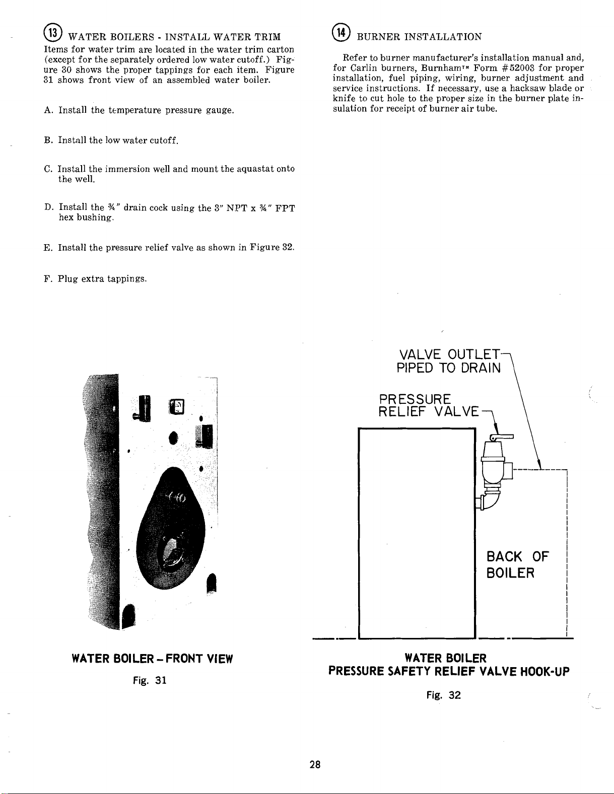
@
WATER BOILERS - INSTALL WATER TRIM
Items for water trim are located in the water trim carton
(except for the separately ordered low water cutoff.) Fig-
30
ure
31
A. Install the temperature pressure gauge.
B.
C.
D.
E.
F.
shows the proper tappings for each item. Figure
shows front view of an assembled water boiler.
Install the low water cutoff.
Install the immersion well and mount the aquastat onto
the well.
Install the
hex bushing.
Install the pressure relief valve as shown in Figure
Plug extra tappings.
%"
drain cock using the
3"
NPT x
%"
FPT
32.
@
BURNER INSTALLATION
Refer to burner manufacturer's installation manual and,
for Carlin burners,
installation, fuel piping, wiring, burner adjustment and
service instructions. If necessary, use a hacksaw blade or
knife to cut hole to the proper size in the burner plate
sulation for receipt of burner air tube.
burn ham^^
Form
#52003
for proper
in-
VALVE OUTLET
PIPED
TO
DRAIN?
PRESSURE
RELIEF VALVE-\
BACK OF
BOILER
WATER BOILER - FRONT VIEW
Fig.
31
WATER BOILER
PRESSURE SAFETY RELIEF VALVE HOOK-UP
Page 29

SECTION
1V
-
OPERATING INSTRUCTIONS
@
ALWAYS INSPECT INSTALLATION BEFORE
STARTING BURNER.
@
FILL HEATING SYSTEM WITH WATER.
STEAM BOILERS
As shown in Figure 1, the normal water line is
from the floor. At the start of each heating season and
once or twice during the season try SAFETY VALVE
to be sure it is in working condition. To do this, fasten wire or cord to lever of valve and pull lever
standing safe distance away from valve.
HOT WATER BOILERS.
In a hot water heating system, the boiler and entire
system (other than the expansion tank) must be full
of water for satisfactory operation. Water should be
added to the system until the boiler pressure gauge
registers normal system design operating pressure. To
insure that the system is full, water should come out
of all air vents when opened.
ON A
MUST NOT EXCEED
BOILER IS EQUIPPED ESPECIALLY FOR
MAXTfiIUM WORKING PRESSURE.
SURE EXCEED'S PRESSURE SETTING OF SAFETY
RELIEF VALVE, IT MUST BE RELIEVED IMMEDIATELY AND THE CAUSE OF RELIEF VALVE FAILURE INVESTIGATED AND CORRECTED. EXCESS
PRESSURE IS DANGEROUS, IN ADDITION, COULD
CALJSE DAMAGE TO HEATING SYSTEM.
DO NOT draw water from boiler while in use. When
adding water while boiler is in operation, do not open
supply valve fully but add water slowly.
HOT WATER SYSTEM THE PRESSURE
-
Fill boiler to normal water line.
46%"
50
POUNDS UNLESS THE
7Q
LBS.
IF
BOrLER PRES-
--
C. CHECK LOW WATER CUTOFF control with water
level at normal water line (see Figure 1). Raise operating control setting to allow burner to operate. Open
boiler drain to allow water level to drop to bottom of
sight glass until burner operation is shut down by
water cutoff.
Close boiler drain and refill to normal water line.
Burner should automatically restart during fill. Reset
operating control.
PROBE
OFF DEVICES REQUIRE ANNUAL INSPECTION
AND MAINTENANCE. Refer to step
Instructions for proper cleaning instructions.
D.
'CHECK OPERATING CONTROL on boiler equipped
with tankless heaters. With burner off, draw hot
water until burner starts,
and check burner shutdown.
@
CLEANWG A NEW STEAM BOILER
Oil, greases
boiler and piping must be removed from the system in
order to prevent an unsteady water line and carry over
of the water into the supply main above
the boiler with steam in the entire system for a few days
allowing the condensate to return to the boiler. If the
condensate can temporarily be wasted, operate boiler only
for the length of time it takes for condensate to run clear.
If the latter cannot be achieved or if the condensate is. returned to the boiler, boil out the boiler using the SURFACE
AN.D FLOAT TYPE LOW WATER CUT-
@
then turn off hot water
&
sediments which accumulate in a new
.boiler. Operate
BLOWOFF connection. See Figure
29.
low
of Service
0
SET
"OFF".
@
facturer's specifications and, for Carlin Burners, according to
@
Before Installation of the boiler is considered complete
the operation of the boiler controls should be checked,
particularly the low water cutoff and the high limit control.
CHECK OPERATING CONTROL OPERATION.
Raise and lower operating control setting as required
to start and stop burner.
WARNING
'Jumper Operating 'Control Terminals: Allow burner
to operate until shutdown by limit. Installation is not
considered complete until this check has been made.
REMOVE JUMPER.
CONTROIlS with burner service switch turned
ADJUST BURNER according to the burner manu-
BurnhamTM Form
TEST CONTROLS
-
#52003.
CHECK HIGH LIMIT CONTROL
-
Drain boiler until water is just visible in gauge glass.
Run temporarily 1%" pipe line from the surface blowoff connection to an open drain or some other location
where hot water may be discharged safely. Do not install valve in this line.
Certain state and local codes may restrict the use of
some of the chemicals listed for cleaning and main-
taining the boiler. Check with local authorities before
proceeding to use these chemicals.
Drain about
container and dissolve into it
and
1
lons of boiler water. See Table
valve 2nd 2dd solution to boiler water thru exposed
tapping.
Use extreme care in handling these chemicals. Caustic
Soda is harmful to skin, clothing, and eyes. Do not
permit the dry material or
to come into contact with skin or clothing.
5
gallons of hot water from boiler into a
1
pound of caustic soda
pound of trisodium phosphate for each
3.
Remove safety
.the concentrated solution
50
gal-
Page 30

QUANTITY CLEANING SOLUTION
BOILER
NO.
PF-504
P F-505
WATER CAPACITY
TO WATER LINE
GALS.
58
69
CAUSTIC
SODA
LBS.
1.2
1.4
TRlSODlUM
PHOSPHATE
LBS.
1.2
1.4
Maintain
the following concentration after boiler ,is cleaned:
NOTE - THE USE OF THESE CHEMICALS MAY BE RESTRICTED IN SOME AREAS.
95%
Sodium Chromate and
Steam Boilers
Hotwater Boilers
-
5%
Sodium Borate water treatment compound at
2
Ib. per 100 gallons of boiler water
-
1
Ib. per 1400 gallons of heating system water
TABLE Ill
Page 31

C. Start burner and operate sufficiently to boil the water
without producing steam pressure. 'Boil for about 5
hours. Open boiler feed pipe sufficiently to permit a
steady trickle of water from the surface blowoff pipe.
Continue this slow boiling and trickle of overflow for
several hours until the water coming from the overflow is clear.
D. Stop burner and drain boiler in a manner and to a
location that hot water can be discharged with safety.
E. Refill (boiler to normal water line. If water in gauge
glass does not appear to be clear, repeat steps A thru
C,
and boil out the boiler for a longer time.
F.
Remove temporary surface blowoff piping, plug tap-
ping and reinstall safety valve. Boil or bring water
temperature to 180°F promptly in order to drive off
the dissolved gases in the fresh water.
G.
If unsteady water line, foaming or priming persist,
install gate valve in Hartford Loop and drain valves
in return main and at boiler and proceed as follows:
1. Connect hoses from drain cocks to floor drain. Close
gate valve in Hartford 'Loop and open drain cock in
return main. Fill boiler to normal water level, turn
on oil burner and operate boiler at this water level
for at least 30 minutes after the condensate begins
to run hot, then turn off burner.
Close all radiator valves. Remove all supply main
air valves and plug the openings in supply
2. Draw about 5 gallons of hot water from boiler into
a. container and dissolve into it the quantities of
caustic soda and trisodium phosphate shown in
Table 3. Remove safety valve from boiler and pour
this solution into
3. Turn on burner and keep operating while feeding
water to boiler slowly. This will raise water level
in boiler slowly so that water will be boiling hot and
will rise slowly into supply main and back through
return main, flowing from drain hose at about
180°F. Continue until water runs clear from drain
hose for at least 30 minutes.
4.
Stop feeding water to boiler but continue operating
burner until excess water in boiler flows out
through supply main and water lowers (by steam-
ing) until it reaches normal level in boiler. Turn
off burner. Drain
Reinstall all supply main air valves. Open gate valve
in Hartford Loop.
5. When boiler has cooled down sufficiently
sheet of sections are not too hot to touch), close
the drain cocks
feed water slowly up to normal level in boiler. Turn
on burner and allow boiler to steam for 10 minutes
then turn off burner. Draw off one quart of water
from bottom gauge glass fitting and discard. Draw
off another quart sample and if this sample is not
clear, repeat the cycle of draining the boiler and
and return main and refilling the boiler until sample is clear.
6.
If the boiler water becomes dirty again at a later
date due to additional sediment loosened up in the
piping, close gate valve in Hartford Loop, open
drain cock in return main, turn on burner and
allow condensate to flow to drain until it has run
clear for at least 30 minutes while feeding water to
boiler so as to maintain normal water level. Turn
off burner, drain boiler, open gate valve in Hart-
ford Loop, then repeat step
.boiler, then reinstall safety valve.
lboiler. Open all radiator valves.
at
boiler and in return main and
1
above.
inain.
(crown-
@
CLEAEilNG A WATER BOILER
in
a
The oil and grease which accumulate
boiler can be washed out in the following manner.
A. Remove safety relief valve using extreme care to avoid
damaging it.
Centain state and local codes may restrict the use of
some of 'the chemicals listed for cleaning and maintaining the boiler. Check with local authori'ties before
proceeding to use these chemicals.
Partially fill boiler and add caustic soda or trisodium
phosphate to the boiler water at the rate of
either chemical per 50 gallons of total water in the
system. See Table 3.
C. Reinstall safety relief valve.
D. Fill the entire system with water.
E. Start firing the boiler.
F.
Circulate the water through the entire system.
G.
Vent the system, including the radiation.
H. Allow boiler water to reach operating temperature, if
possible.
I.
Continue to circulate the water for a few hours.
J.
Stop firing the boiler.
K.
Drain the system in a manner and to a location that
hot water can be discharged with safety.
L. Remove plugs from all available returns and wash the
water side of the boiler as thoroughly as possible, using a high-pressure water stream.
M.
Refill the system with fresh water.
BOILER WATER TREATMENT
Certain state and local codes may restrict the use of some
of the chemicals lis'ted for cleaning and maintaining the
boiler. Check with local authorities before proceeding to
use these chemicals.
Add boiler water treatment compound as
chromate boiler water treatment compound consisting of
95% sodium chromate and 5% sodium borate has been
tested and found reliable. These tests have shown that
the material, when used and maintained at the concentrations listed below, is effective in controlling and arresting corrosion. These chemicals may be purchased from
any reliable chemical company.
A. Low pressur. steam boilers, such as the PF-5 Series
should be miintained with a chromate concentration
of 2 ljb./100 gal. (see Table 3) of boiler water (2200
ppm). This concentration will be effective where all
or practically all of the condensate is returned to the
boilers.
new- hot water
1
lb. of
nezded. A
Page 32

B. Hot Water Boilers.
The use of chromxte boiler water treatment compound
in a water boiler involves considerations. Too high a
concentration must be avoided as it may damage pump
seals. Therefore, with a lower level of protection, it
is necessary to take even greater
free oxygen out of the system. Free oxygen can enter
from system leaks, faulty vents, or vents improperly
located with regard to pumps and from makeup water.
Hot water heating boilers should be maintained with a
chromate concentration of
water. See Table
@
Make pH or Alkalinity Test.
After boiler and system have been cleaned and refilled
as previously described, test the pH of the water in the
system. This can easily be done 'by drawing a small
sample .of boiler water and testing with hydrion paper
which is used in the same manner as litmus paper, except
it gives specific readings.
of the small hydrion dispenser gives the reading in pH.
Hydrion paper is inexpensive and obtainable from any
chemical supply house or through your local druggist. The
pH should be higher than
of the washout chemical (caustic soda), if necessary, to
bring the pH within the specified range.
3.
A
small color chart on the side
7,
but lower than
precaultions to keep
1
lb.11400 gal. of boiler
11.
Add some
If, during normal operation, it is necessary to add water
to this boiler more frequently than once a month consult
a qualified service technician to check your system for
leaks. A leaky system will increase the volume of make-up
water supplied to the boiler which can significantly shorten the life of the boiler. Entrained in make-up water are
dissolved minerals and oxygen. When the fresh, cool
make-up water is heated in the boiler the minerals fall
out as sediment and the oxygen escapes as a gas. Both
can result in reduced boiler life. The accumulation of
sediment can eventually isolate the water from contacting
the cast iron. When this happens the cast iron in that
area gets extremely hot and eventually cracks. The presence of free oxygen in the boiler creates a corrosive atmosphere which; if the concentration becomes high
enough, can corrode the cast iron through from the inside.
Since neither of these failure types are the result of a
casting defect the warranty does not apply. Clearly it is
in everyone's best interest to prevent this type of failure.
The maintenance of system integrity is the best method
to achieve this.
Page 33

SECTION V - SERVICE INSTRUCTIONS
0
IMPORTANT - See Item
Instructions if it be comes necessary to add water to the
boiler more frequently than once a month.
I
@
GENERAL - Inspection should be conducted annual-
ly. Service as frequently .as specified in paragraphs below. While service or maintenance is being done, electrical power to the boiler must be "off".
@
CLEAN THE 'BOILER HEATING SURFACES
at
AND FLUE
end
of
the heating season.
A. CLEAN THE VENT SYSTEM
be checked annually for:
1.
Obstructions.
2.
Accumulations of soot.
3. Deterioration of vent pipe or vent accessories due
to condensati.on or other reasons.
4.
Proper support - no sags, particularly in horizontal
runs.
5.
Tightness of joints.
Remove all accumulations of soot with wire brush and
vacuum. Remove all obstructions. Replace all deteriorated parts and support properly. Seal all joints.
B. CLEAN THE BOILER FLUEWAYS
1.
Remove the smokepipe.
2.
Remove the jacket top and left side panels.
3.
Remove the canopy being careful n,ot to damage the
cerafelt gasket.
4.
Loosen nuts securing the flue cleanout plates and
remove the plates. The insu1,ation should be removed with the plates taking care not to damage the
insulation.
5.
Using a
(36"
top and side using horizontal and diagonal strokes
for best results.
least once each year, preferably at the
1%''
diameter wire or fibre bristle brush
handle) clean the flueways. Brush from the
@
under Operating
-
Vent system should
5.
Reinstall jacket top and left side panels.
6.
Reinstall smokepipe.
MAINTENANCE OF LOW WATER,CUTOFF DE-
VICE'S
PROBE AND FLOAT TYPE LOW WATER CUTOFF
DEVICES REQUIRE ANNUAL INSPECTION AND
MAINTENANCE.
A. PROBE TYPE LOW WATER CUTOFF
Athough these devices are solid state in the operation,
the probe
boiler water and subject to fouling.
It is
the boiler tapping annually and inspect that probe for
accumulation of scale or sediment.
Follow these steps to inspect, clean and/or replace the
probe
Turn off electric service to the boiler.
Drain boiler water t,o a level below the tapping for
the probe.
Disconnect wiring connections between the low
water cutoff control and the probe.
Dismount the low water cutoff control from the
probe.
Unscrew the probe from the boiler tapping.
Inspect that portion of the probe that is exposed to
the boiler water for a scale or sediment buildup.
Light deposits may be removed by wiping the probe
with a damp cloth. Wiping the probe with a cloth
soaked in vinegar will remove more tenacious lime
deposits. The most stubborn deposits may be re-
moved from the probe by using a diluted amount (3
part of water to
po4).
is exposed to possible contamination in the
impoptant to physically remove the probe from
:
1
part) of phosphoric acid (H,
C. CLEAN TOP OF BOI'LER SECTIONS.
Brush and vacuum the tops of the boiler sections.
D. CLEAN THE FIREBOX
1.
Disconnect fuel line(s) and remove burner and
burner mounting plate.
2.
Using wire or fibre bristle brush clean crown of
boiler and inside of water legs.
.E. REASSEMBLE BOILER
1.
Install the canopy taking care to align the cerafelt
strips. If strips are damaged replace as needed.
2.
Reinstall burner mounting plate to front section
making sure Flextex rope gasket is in place and
forms gas tight seal. If gasket is damaged, replace.
3.
Bolt burner to burner mounting plate. Inspect gas-
ket to assure adequate seal. Replace if damaged.
Connect oil line(s) and/or gas line (s).
4.
Reinstall flue plates making sure gasket on each
plate is in place and forms gas tight seal. If damaged, all edges of the cleanout plates should be sealed with Silastic sealant when reinstalled until insulation can be replaced.
Exercise cautioii when handling phosphoric acid and follow the instruction label on its container.
Wire brushing of the probe is not recommended as
the soft platinum guard ring sandwiched between
the ceramic insulators may be damaged. 'Care must
be taken not to damage this ring in any way or the
useful life of the probe may be shortened.
Clean the pipe threads of the probe to remove old,
hardened pipe dope and other foreign matter.
Apply a moderate amount of good quality pipe dope
to the pipe threads on the probe, leaving the two
end threads bare. Do not use PT'FE (Teflon) tape.
Screw the probe into the boiler tapping.
Mount the low water cutoff control on the probe.
Reconnect the control to probe wiring.
Fill the boiler to its normal waterline.
Add boiler water treatment compound as needed
(see Table
Restore electric service to .the boiler.
Fire burner to bring the water in the boiler to a
boil tadrive off free oxygen.
3).
Page 34

18.
WARNING - BEFORE RETURNING BOILER TO
:
SERVICE
procedure on page 29.
Follow the low water cutoff check out
a
GENERAL MAINTENANCE CONSIDERATIONS
A. Keep radiators and convectors clean.
B. FLOAT TYPE LOW WATER CUTOFF
During the heating season, if an external low water
cutoff is on the boiler, the blow of! valve sh,ould be
opened once a month (use greater frequency where
conditions warrant), to flush out the sediment chamber
so the device will be free to function properly.
Low water cutoffs and water feeders should be dismantled annually by qualified personnel, to the extent
necessary to insure freedom from obstructions and proper
functioning of the working parts. Inspect connecting
lines to boiler for accumulation of mud, scale, etc., and
clean as required. Examine all visible wiring for brittle
or worn insulation and make sure electrical contacts are
clean and that they function properly. Give special attention to solder joints on bellows and float when this type
of control is used. Check float for evidence of collapse and
check mercury bulb (where applicable) for mercury separation
PAIR MECHANISMS IN THE FIELD. Complete re-
placement mechanisms, including necessary gaskets and
installation instructions, are available from the manufacturer.
@
Item
See Burner Manual for burner tests and adjustments.
orr discoloration. DO NOT ATTEMPT TO RE-
Check burner and controls at least once a year. See
@
under Operating Instructions for control checks.
B.
If a hot water radiator is hot at the bottom but not at
the top, it indicates that air has accumulated inside
and should be vented. To vent radiator, hold small cup
under air vent (located near top of radiator), open
vent until water escapes and then close.
C. If much water is added to system, it is advisable to
heat system to a high temperature and vent again.
This will make less venting necessary during the
winter.
D. Where an expansion tank is used, make sure that neith-
er the tank nor its drain pipe is exposed to freezing
temperatures. Never place valves in piping leading to
or from expansion tank.
E. Boiler and system cleaning will help assure trouble
free operation. See Item
structions for procedure.
@
ATTENTION TO BOILER WHILE NOT IN OP-
ERATION
A. IMPORTANT
IF BOILER IS NOT USED DURING WINTER
TIME, IT MUST BE FULLY DRAINED TO
VENT FREEZE DAMAGE.
B. Spray inside surfaces with light lubricating or crank-
case oil using gun with extended stem so as to reach
all comers.
under Operating In-
@
PRE-
,
@
LUBRICATE BOILER COMPONENTS according
to manufacturer's instructions. Generally, this involves
the oil burner and circulator. This includes the type of
lubricant to use, frequency of lubrication, and points to
lubricate.
C. With steam boilers, at end of season add sufficient
water to fill boiler to top of water column and leave
it that way until fall when water should be drained
again to proper level. If at this time boiler water is
dirty, drain water, flush out boiler, and refill with
clean water to prescribed water level.
Page 35

SECTION VI REPAIR PARTS
All Repair Parts can be ordered through the nearest Burnham Regional Sales Office or Manufacturer's Representative
for delivery from Lancaster.
These offices can advise as
to
the availability
of
their products and repair parts from a more local source.
BURNHAM CORPORATION - REGIONAL OFFICES
Burnham Corporation - Western Region
A.
P.O. Box
Lancaster, PA
(717) 293-5836
Fax
3079
:
293-5832
17604
B. Burnham Sales Corporation - Northeast Region D. Burnham Corporation - Mid Atlantic Region
19-27
Mystic Avenue
Somerville, MA
(617) 625-9735 (717) 293-5861
Fax
:
625-9736
02145
Contact Regional Office Indicated for your State:
Alabama
Alaska
Arizona
Arkansas
California
Colorado
Connecticut
Delaware
Florida
Georgia
Hawaii
Idaho
Illinois
Indiana
Iowa
Kansas
Kentucky
Louisiana
Maine
Maryland
Massachusetts
Michigan
Minnesota
Mississippi
Missouri
Montana
Nebraska
Nevada
New Hampshire
New Jersey
Mercer County
All other Counties
Burnham Corporation
C.
100
Davidson Avenue
Somerset, NJ
(908) 560-9800
Fax
:
560-9814
P.O. Box
3079
Lancaster, PA
Fax
:
293-5855
08873
17604
-
Metropolitan Region
New Mexico
New York
Albany, Fukon, Montgomery, Rensselear,
Saratoga, Schenectady, Schoharie, Warren,
Washington Counties
Sullivan County D
All other Counties C
North Carolina A
North Dakota A
Ohio
Athens, Belmont, Gallia, Jefferson, Lawrence,
Meigs, Monroe, Washington Counties D
All other Counties A
Oklahoma A
Oregon
Pennsylvania
Rhode Island
South Carolina A
South Dakota A
Tennessee A
Texas
Utah A
Vermont
Virginia
Arlington, Accomack, Clarke, Fairfax,
Frederick, Fauquier, Loudoun,
Northampton, Prince William Counties D
All other Counties
Washington
Washington, D.C.
West Virginia
Wisconsin
Wyoming
Canada A
A
B
A
A
B
Page 36

,'
TANKLESS HEATER / COVER
r
@
PLATE
GASKET
OBSERVATION PORT OR PEEP
SIGHT ASSEMBLY
0
64
f'xZUCERAFELT STRIP
0
/
'
.
'
,
/
'
,
DIA. ROPE GASKET (STEEL MOUNTING PLATES ONLY1
[
$-10 TIE ROD W/ WASHERS 8 NUTS
@
Fig.
33
Page 37

ITEM
NO.
1
2
3
DESCRIPTION
Front Sdon
"C" Center Seotion
Optional
"CX" Center Section (with 3"
Rear Section
7" Cast Iron Slip Nipple
3"
Tie Rod Sets
Cleanouk Cover Assmbly
Tankless Htr/Oover Plate Gskt.
Tankless Hkr (1
Blank
Tapped Heater Cover Plate
Burner Mounting Plate Assy.
Cast
Steel Mtg. Plate Assy. for
Observation Po& Assy.
Pee Sight Assembly (All
Peep Sight, Websh Burner
Burner Mtg. Plbte Insulation
-
"CT" Center, I.L.O.
-
Max. # (Center Section
"C"
with Tankless
Supply Tapping)
Cast Iron Slip Nipple
Tie Rod Bundle, 26-%" LG
Tie Rod Bundle, 37-%" LG
Tie Rod Bundle
Tie Rod ~undle: 67-
(1 each "CT" Section)
OR
Hater
(1 each "CT"
OR
(1 each "CT"
(w/Observation Port Assy.
and Mtg. Plate Insulation)
Imn Burner Mounting
Plute Aesmbly for:
Carlin 301 Burner
Carlin 701 Burner
Garlin 801 Burner
Powerflame C1 Burner
G&P R6 Burner
G&P R-8 Burner
G&P R-10 Burner
Powerflame C2 Burner
Powerflame C3 Burner
Carlin 1050 FFD Burner
Carlin 1150 FFD Burner
Webster #JBI Bur. PF504
Webster
Webster
(Cast:
Cover (1 each)
Shutter (1 each)
Glass (1 eadh
Shutter ~mdk (1 each)
Shutter Spring (1 each)
Shu~r Spring Pin (1 ea.)
Shutter Handle Knob (1
Outer Gasket (1 eadh)
Inner Gasket (1 each)
&g. Plates except Webster bnr.
Pyrex Sight Glass
Sight Glass Gasket (2 each
Conduit Bushing (Peep
Retainer,
Cast Iron Burner
Insulation ,(Carlin 301/
601/801e Powerflame C1;
R-&
G&P
Steel Mtg. Plate Insulation
Insulation depends on
burner used. Colutaet sales
office for repair parts.
Heah-)
-
--
48-%"
%"
ea.
"CT" Sctn.)
Cover Plate
-
Stem only)
-
Water only)
#
JB1 Bnr, PF505-13
#
JB2 Burner
Iron Mtg. Plate)
'(1 each)
1
each)
Mtg. Plate
and ABC Bnrs.)
LG
LG
&.)
%el
~ig&
REPAIR PARTS FOR BARE
PART
NO.
6172501
nm03
BOILER ASSEMBLY
508
BOILER SIZE/QUANTITY
509 510 511 512 513 514 515 516 517 518 519
11111111111111
6 7 7 8
34446568667788
9
10 10
11
12 13 13 14
520 521
15
16
-
Page 38

BARE BOILER ASSEMBLY
(Continued)
ITEM
NO.
17
18
19
DESCRIPTION
Firewall PMes
Pressure Relief Door Assembly
Canopy Assembly
Canopy Assem3bly,
Canopy A,ss&nbly,
Canopy Assembly,
Canopy Assembly,
Canopy Assembly,
Canopy Assembly,
Canopy Assembly,
Uanopy Assembly,
Canopy Assembly,
Canopy Assmbly,
Canopy A,ssembly,
Canopy A,ssembly,
Canopy Asmbly,
Canopy Assembly,
Canopy Sssmbly,
Canopy Assembly,
Canopy Assembly,
Canopy Assmbly,
Uanopy Insulation
Canopy Insulation,
Ganopy Insulation,
Canopy Insulation,
Canopy Insulhtion,
Canopy Insulation,
Canopy Insulation,
Canopy Insulation,
Canopy Insulation,
Canopy Insulation,
Uanopy Insulation,
Canopy Insulktion,
Canopy Insulation,
Canopy Insulation,
Canopy Insulation,
Canopy Insulation,
Canopy Insulation,
Canopy Insulation,
Canopy Insulhtion,
Cerafelt Gaskek
10
Fout
Roll
15
Foot
25
Flue Damper Assembly
Flue Damper Assy.,
Flue Dannper Assy.,
Flue Drwnper Assy.,
Roll
Foot Roll
PF-504
PF-505
PF-506
PF-507
PF-508
PF-509
PF-510
PF-51'1
PF-512
PF-513
PF-514
PF-515
PF416
PF-517
PF-518
PF-518
PF-520
PF-521
PF-504
PF-505
PF-506
PF-507
PF-SO8
PF-509
PF-510
PF-511
PF-51'2
PF-513
PF-514
PF-515
PF-516
PF-617
PF-518
PF-519
PF-620
PF-621
810"
14"
18"
Dia.
Dia.
Dia.
PART BOILER SIZE/QUANTITY
NO.
504 505 506 507 508 509 510 511 512 513 514 515 516 517 518 519 520 521
Page 39

WATER TRIM REPAIR PARTS
Common Parts (Boiler Sizes 504 thru 521) Quantity PART
Aquastat Controller, Honeywell L4006A2015
%"
%"
NPT
NPT
NPT
506 509 512 519
SO4
and
to to to to
508 511 518 521
I----
-I---
-
-
1--
----
1----
-
11--
-
- -
----
I----
11--
---1-
----
I-----
11--
---
----
Immersion Well, Honeywell 123871A,
Temperature Pressure Gauge, A-metek 144840,O-100 PSI
%"
Pipe Plug,
Pipe Plug,
Pipe Plug, 1" NPT, Countersunk, Black (Low Water Cut-Off Tappings)
Pipe Plug, 3" NPT, Square Head, Black
(Botbom Washout Tapping and Low Wmater Cut-Off Tapping) 2 806603514
Hex Bushing, 3" NPT x
Drain Cock, ConBraCo 31-606-01,
Specific Parts Boiler Size
Relief Valves set at 50 PSI: 505
OonBl'aCo 10-303-10,
ConBraCo '10-214-10,l" NPT x 1" NPT
W&ts 740,l" NPT x 1%" NPT
Wdts 740,l
Watk 740,1%" NPT x 2" NPT
Safety
Valve Piping:
Hex Bushing, 3" NPT
Hex Bushing, 3" NPT x
Hex Bushing, 3" NPT x 1%" FPT, Black
Hex Bushing, 3" NPT x
Pipe Nipple,
Pipe Nipple,
Pipe Nipple, 1%" NPT x Close, Black
Pipe Nipple, 1%" NPT x Close, Black
Street Elbow,
Street Elbow, 1" NPT x 9O0, Elack
Street Elbow, 1%" NPT x 90°, Black
Strset Elbow, 1%" NPT x 90°, Elack
NPT, Square Head, Elack (Gauge Glass Tappings) 2 806603507
3/a
"
NPT, Square Head, Black (Reverse Acting Control Tappings) 2 806603512
94"
FPT, Black (Bottom Drain Tapping)
%"
X"
NPT x
S/a
"
NPT
x
1
%
"
NPT
x
V"
FPT, Black
1"
FPT, Black
1%"
FPT, Black
%
"
NPT x Clsase, Black
1"
NPT x Close, Black
3/a"
NPT x 90°, Black
1
1
1
2
1
1
1
1
1
-
1
-
1
1
-
1
80160400
80160462
8056028
806603517
806600509
806603001
81660302
81660330
81660305
81660308
81660309
806600509
806600559
806600560
806600542
806600022
806600004
806600018
806600008
806601501
806601514
806601516
806601517
NO.
STEAM TRlM REPAIR PARTS
Common Parts (Boiler Sizes 504 thru 521)
Pressuretrol, Honeywell PX404A1009
Water Gauge Set, ConBraCo 20-104-10, w/81/zW Lg. glass
Steam Pressure Gauge, Ametek 144350,3%"
Syphon,
E-xtension Adapter,
Pipe Nipple,
Hex Bushing,
Hex Bushing, 3" NPT
Pipe
Pipe Plug,
Pipe Plug, 3" NPT, Square Head, Black
Drain Cock, ConBmCo 31-606-01,
Lowest Permissible Water Level Plate, Fonm 1204
Sheet Metal Screw, #8 x
Specific Parts
Safety Valves set at 15 PSI: 507 511 514 520
Black Tees (For Safety Valve)
%"
x 90" (4%" leg) (Pressuretrol)
3"
Plug,
%"
1"
ConBraCo 13-202-08,l" NPT x
ConBraCo 13-213-08,1%" NPT x 1%" NPT
ConBraCo 13-214-08,1%" NPT x
ConBmCo 112-205-08,2" NPT x 2" NPT
ConRraCo 12-20&08,2%" NPT x 2%" NPT
ConBraCo 12-208-(h8
3" NPT x 3" NPT x
3" NPT x 3" NPT x 1%" NPT
3" NPT x 3" NPT x 1%" NPT
3" NPT x 3" NPT x
3" NPT x 3" NPT x 2%" NPT
3" NPT
%"
NPT x
%"
FPT (Water Gauge Set) 2
NPT x Close, Black (Safety Valve)
%"
NPT
x
%"
FPT, Black (Syphon)
x
V"
FPT, Black (Bottom Drain Tapping)
NPT, Square Head, Black
NPT, Countersunk, Black
%"
NPT
M"
Lg., Phillips Truss Head, AB Plated
1"
NPT
2"
3"
NPT x 3" NPT
1"
NPT
2"
NPT
NPT
Dia.
(Reverse Aoting Control Tappings) 2
(Low Water Cut-Off Tappings) 2
(Eottom Washout Tapping)
505 508 512 515
504
to
to to to 521
I-----
I----
-
-
I---
-
----
-----
1-----
-
I----
--1---
-
- -
----
-----
Quantity
1--
1
1--
1
PART
NO.
1
1
1
1
1
1
1
1
1
1
2
80160300
805602!5
8056022
806603006
806604501
80660039
806600508
-
1
-
1
Page 40

Page 41

ITEM
NO.
DESCRIPTION NO.
1
Jacket. Right Side Panel Sub-Assembly
604 60426042
606
506 604a5062
607 '604.26078
508 60426082
Jacket R.S. Integral Panel Assembly
609 60465044
610 60426064
611 60425W
512 60425074
Jacket L.S. Panel Sub-Assembly
604 60426043
606 60425063
606 60426063
507 60426073
608
Jack& L.S. Integral Panel Assembly
609 60426045
510 60426065
611 60426066
612 60426076
Jacket L.S. Panel Filler Piece Assembly
Jacket Rear Fanel hssembly
Jacket Upper Front Panel Assembly
Jacket Lower Front Panel Assembly
Jacket Top Panel Assembly
604 604250461
606 604250561
606 609250661
607 604260761
608 609250861
609 604260961
610 604261061
611 604261161
612 604261261
613 60425111
614 60426146l
616 604261561
616
617 604261761
618 604251S61
519 604261961
620 60425'2061
621 60rVW2161
Jacket Top Integral Panel Assembly
612-616 60925231
616-621 60826241
Jacket Top Panel Filler Piece Assembly
Paper
Bag
Containing:
Sheet Metal Screws
#
8 x %"
T~ss
Leg Spacer
Lg. Phillips,
Hd, Type AB Plt'd.
BART
(604821)
60425OEd
(509-521)
(504-521)
6046083
(509-621)
6042501
6042602
6042503
604%221
604261661
(612-521)
6d4k525
80860000
806603618
Page 42

(THIS
PAGE
LEFT INTENTIONALLY BLANK)
Page 43

(THIS
PAGE LEFT INTENTIONALLY BLANK)
Page 44

SERIES 5B, SERIES 8B, PF-5 SERIES,
FD SERIES, WOODLANDER,
SAHARA INDIRECT WA TER HEA TER
DUO-RA DTM,
AND CAST IRON RADIA TION
V-9
SERIES,
*
LIMITED WARRANTY
Burnham Corporation warrants to the original owner at the original installation site that products manufactured by Burnham, America's
Boiler Company comply, at the time of manufacture, with recognized Hydronics industry regulatory agency standards and requirements
then in effect and will be free from defects in materials and workmanship for a period of one year after the date of installation.
The remedy for
conditions of normal use and does not extend to liability for incidental, special or consequential damages or losses such as loss
of the use of the products, inconvenience, loss of time or labor expense involved in repairing or replacing alleged defective product. Burnham Corporation shall have no responsibility for the performance of any product sold by it under conditions varying
materially from those under which such product is usually tested under existing industry standards, nor for any damage to the
product from abrasion, erosion, corrosion, deterioration or the like due to abnormal temperatures or the influence of foreign matter
or energy, nor for the design or operation of any system of which any such product may be made a part or for the suitability of
any such product for any particular application.
For products or parts not manufactured by
respects, conform and be limited to the warranty actually extended to Burnham Corporation by its vendors.
Warranty service can be obtained by contacting the original installer of the product and providing him with a detailed description of any
apparent defect. If this procedure fails to result in satisfactory warranty service, the owner should notify
America's Boiler Company, P.O. Box 3079, Lancaster, PA 17604. Transportation to a factory or other designated facility for repairs of any
products or items alleged defective shall, in all events, be the responsibility and at the cost of the owner.
Notwithstanding any of the above provisions, (1) failures resulting from misuse, improper installation or lack of maintenance are
not covered by this warranty, and
product found to be defective.
Equipment furnished by the Buyer, either mounted or unmounted, and when contracted for by the Buyer to be installed or handled
is not covered by this warranty.
operation, warranty, performance, or any other liability connected thereto.
The foregoing provisions of this
extent that any such provision would otherwise have an unconscionable result or would otherwise be inconsistent with applicable
law, such provision shall be limited in effect to the minimum extent necessary to avoid such unconscionable result or inconsistency
with applicable law.
breach of this warranty is expressly limited to the repair or replacement of any part found to be defective under
-
Except as provided below with respect to products or parts not manufactured by Burnham Corporation,
Burnham Corporation, the warranty obligations of Burnham Corporation shall, in all
Burnham Corporation, Burnham,
(2)
Burnham Corporation's liability under this warranty shall not exceed the selling price of the
Burnham Corporation does not assume any responsibility in connection with such equipment,
WARRANTY
shall be effective to the maximum extent permitted by applicable law, and, to the
Any implied warranties, including implied warranties of merchantability and fitness for a particular purpose shall, to the
extent permitted by applicable law, be limited
permitted by applicable law, the remedies for breach of any such implied warranty shall be limited to the remedies set
forth above with respect to a breach of the express limited warranty provided. With respect to the limitations on implied
warranties set forth above, Burnham Corporation hereby notifies each person to whom such warranty is made as follows:
Some states do not allow limitations on how long an implied warranty lasts or the exclusion or limitation of incidental or
consequential damages, so the above limitations or exclusion may not apply to you. This warranty gives you specific legal
rights, and you may also have other rights which vary from state to state.
in
duratiyl to a period of one year after the date of installation. To the extent
AMERICA'S BOILER COMPANY
Burnham Corporation
Lancaster,
PA
17604
10193
 Loading...