

Burnham 4FHL-345A, 4FHL-107A, 4FHL-127A, 4FHL-209A, 4FHL-240A Installation And Operating Instructions Manual
...Page 1
INSTALLATION AND OPERATING
INSTRUCTIONS FOR
BURNHAM COMMERCIAL
4FH SERIES FIRETUBE BOILERS
Commercial Boilers
This manual must only be used by a qualied heating installer/service technician.
BEFORE installing, read all instructions in this manual and all other information
shipped with the boiler. Post all instructions and manuals near the boiler for reference
by service personnel. Perform steps in the order given. Failure to comply could
result in severe personal injury, death or substantial property damage.
Ce manuel ne doit être utilisé que par des techniciens qualiés en entretien et
installation d’appareil de chauffage. Lire l’ensemble des directives et toute autre
information reçue avec la chaudière AVANT l’installation. Conserver ces directives
près de la chaudière an que le personnel d’entretien puisse s’y référer. Exécuter les
étapes dans l’ordre donné. Ne pas se conformer aux directives peut engendrer des
blessures graves, la mort ou d’importants dommages matériels.
For service and repairs to the heating plant, call your local representatives. When seeking information
on the boiler, provide series and size designation shown on rating plate.
Boiler Number __________________ Type Firing________________ Type System _________
Project______________________________________________________________
Address_________________________________________________ Phone No._____________
1
Page 2
IMPORTANT INFORMATION -
READ AND SAVE THESE INSTRUCTIONS FOR REFERENCE
All boilers must be installed in accordance with National, State and Local Plumbing, Heating and Electrical Codes
and the regulations of the serving utilities. These Codes and Regulations may differ from this instruction manual.
Authorities having jurisdiction should be consulted before installations are made. In all cases, reference should be
made to the following Standards:
USA BOILERS
A. Current Edition of American National Standard ANSI/NFPA 31, “Installation of Oil Burning Equipment,” for
recommended installation practices.
B. Current Edition of National Fuel Gas Code, NFPA 54/ANSI Z223.1.
C. Current Edition of American National Standard ANSI/NFPA 211, “Chimneys, Fireplaces, Vents, and Solid Fuel
Burning Appliances,” for venting requirements.
D. Current Edition of American Society of Mechanical Engineers ASME CSD-1, “Controls and Safety Devices for
Automatically Fired Boilers,” for assembly and operations of controls and safety devices.
E. All wiring on boilers installed in the USA shall be made in accordance with the National Electrical Code and/or
Local Regulations.
CANADIAN BOILERS
A. Current Edition of Canadian Standards Association CSA B139, “Installation Code for Oil Burning Equipment,”
for recommended Installation Practices.
B. The equipment shall be installed in accordance with the current Installation Code for Gas Burning Appliances and
Equipment, CSA B149, and applicable Provincial Regulations for the class; which should be carefully followed in
all cases. Authorities having jurisdiction should be consulted before installations are made.
C. All wiring on boilers installed in Canada shall be made in accordance with the Canadian Electrical Code and/or
Local Regulations.
Hazard denitions
The following dened terms are used throughout this manual to bring attention to the presence of hazards of various
risk levels or to important information concerning the life of the product.
Indicates an imminently hazardous situation which,
if not avoided, will result in death, serious injury or
substantial property damage.
Indicates a potentially hazardous situation which, if
not avoided, could result in death, serious injury or
substantial property damage.
Indicates a potentially hazardous situation which, if
not avoided, may result in moderate or minor injury
or property damage.
Indicates special instructions on installation,
operation, or maintenance which are important but
not related to personal injury hazards.
Dénitions des dangers
Les termes suivants sont utilisés tout au long de ce manuel an de souligner la présence de dangers dont le
niveau de risque varie ou de mettre en relief de l’information cruciale quant à la durée de vie du produit.
Indique une situation de danger imminent qui, si
elle n’est pas évitée, peut causer la mort, de graves
blessures ou d’importants dommages matériels.
Indique une situation de danger potentiel qui, si elle
n’est pas évitée, cause la mort, de graves blessures
ou d’importants dommages matériels.
Indique une situation de danger potentiel qui, si elle
n’est pas évitée, peut causer des blessures mineures
ou de légers dommages matériels.
2
Indique des directives particulières, importantes,
mais sans risque de blessure, lors de l’installation,
de l’utilisation ou de l’entretien.
Page 3
This boiler has a limited warranty, a copy of which is printed on the back of this manual.
It is the responsibility of the installing contractor to see that all controls are correctly installed and are operating properly
when the installation is complete. The warranty for this boiler is valid only if the boiler has been installed, maintained and
operated in accordance with these instructions.
Cette chaudière est sous garantie limitée, dont un exemplaire apparaît à l’arrière du manuel.
Il incombe à l’installateur de s’assurer que les dispositifs sont correctement xés et en état de marche au terme de
l’installation. La garantie pour cette chaudière est valable seulement si le produit est installé, entretenu et utilisé selon
les présentes directives.
DO NOT store or use gasoline or other ammable vapors or liquids in the vicinity of this or any other appliance.
If you smell gas or fuel oil vapors, do not try to operate the burner/boiler system. Do not touch any electrical switch
or use any phone in the building. Immediately call the gas or oil supplier from a remotely located phone.
Burner/boiler systems produce steam or hot water in a pressurized vessel by mixing extremely ammable gaseous,
liquid or solid fuels with air to produce combustion and very hot products of combustion. Explosions, res severe
personal injury, death and/or property damage will result from improper, careless or inadequate installation, operation
or maintenance of fuel-burning and boiler equipment.
NE PAS entreposer ou utiliser de l’essence ou toute autre matière inammable gazeuse ou liquide à proximité de la
chaudière ou de tout autre appareil.
Si vous sentez une odeur de gaz ou de mazout, ne pas tenter d’utiliser le système de brûleur/chaudière. Ne pas
toucher les interrupteurs ni se servir des téléphones du bâtiment. Appeler immédiatement le fournisseur de gaz ou
de mazout à partir d’un autre endroit.
Les systèmes de brûleur/chaudière produisent de la vapeur ou de l’eau chaude en mélangeant des carburants
hautement inammables gazeux, liquides ou solides avec de l’air dans une cuve sous pression pour produire une
combustion et des résidus très chauds. Des explosions, des incendies, des blessures graves, la mort ou d’importants
dommages matériels peuvent découler d’une installation, d’une utilisation ou d’un entretien inadéquat ou négligé
de l’équipement de combustion et de la chaudière.
3
Page 4
Improper installation, adjustment, alteration, service or maintenance can cause property damage, personal injury
or loss of life. Failure to follow all instructions in the proper order can cause personal injury or death. Read and
understand all instructions, including all those contained in component manufacturers manuals which are provided
with the appliance before installing, starting-up, operating, maintaining or servicing this appliance. Keep this manual
and literature in legible condition and posted near appliance for reference by owner and service technician.
Keep boiler area clear and free from combustible materials, gasoline and other ammable vapors and liquids.
This boiler requires regular maintenance and service to operate safely. Follow the instructions contained in this manual.
Installation, maintenance, and service must be performed only by an experienced, skilled and knowledgeable installer
or service agency.
All heating systems should be designed by competent contractors and only persons knowledgeable in the layout
and installation of heating systems should attempt installation of any boiler.
It is the responsibility of the installing contractor to see that all controls are correctly installed and are operating
properly when the installation is completed.
Installation is not complete unless a pressure relief valve is installed.
This boiler is NOT suitable for installation on combustible ooring.
Do not tamper with or alter the boiler or controls. Retain your contractor or a competent serviceman to assure that
the unit is properly adjusted and maintained.
Clean boiler at least once a year - preferably at the start of the heating season to remove soot and scale. The inside
of the combustion chamber should also be cleaned and inspected at the same time.
Have Burner and Controls checked at least once a year or as may be necessitated. Do not operate unit with jumpered
or absent controls or safety devices. Do not operate unit if any control, switch, component, or device has been
subject to water.
Toute installation, altération, réparation, ou tout réglage ou entretien inadéquat peut provoquer des dommages
matériels, une blessure ou une perte de vie. Ne pas se conformer aux directives dans l’ordre donné peut causer des
blessures ou la mort. S’assurer de bien les comprendre, y compris celles des manuels du fabricant accompagnant
les composants fournis avant d’installer, d’utiliser, de réparer, de démarrer ou d’entretenir cet appareil. Conserver ce
manuel et toute autre documentation en bonne condition près de l’appareil aux ns de référence pour le propriétaire
ou le technicien en entretien et réparation.
Garder l’espace autour de la chaudière dégagé et exempt de matières combustibles, d’essence et d’autres vapeurs
et liquides inammables.
Pour fonctionner de façon sécuritaire, cette chaudière nécessite un entretien régulier. Suivre les directives de ce
manuel.
L’installation, les réparations et l’entretien doivent être effectués uniquement par un installateur ou un organisme
de service expérimenté et qualié.
Tout système de chauffage devrait être conçu par des entrepreneurs compétents, et seules les personnes qualiées
pour l’installation de tel système devraient s’en charger.
Il incombe à l’installateur de s’assurer que les dispositifs de contrôle sont correctement xés et en état de marche
au terme de l’installation.
L’installation n’est pas terminée tant qu’une soupape de sûreté n’est pas xée.
Cette chaudière NE PEUT être installée sur un plancher combustible.
Ne pas modier la chaudière ou ses commandes. S’assurer que l’unité est correctement réglée et entretenue auprès
d’un entrepreneur ou d’un technicien compétent.
Nettoyer la suie et le tartre accumulés au moins une fois par année, si possible, au début de la saison froide. Au
même moment, nettoyer et inspecter l’intérieur de la chambre de combustion.
Faites vérier le brûleur et ses commandes au moins une fois par an ou lorsque nécessaire. Ne pas faire fonctionner
si les commandes ou les dispositifs de sûreté sont absents ou installés à l’aide de cavaliers. Ne pas faire fonctionner
si une commande, un interrupteur, un composant ou un dispositif est entré en contact avec de l’eau.
4
Page 5
Appliance materials of construction, products of combustion and the fuel contain alumina, silica, heavy metals,
carbon monoxide, nitrogen oxides, aldehydes and/or other toxic or harmful substances which can cause death or
serious injury and which are known to the state of California to cause cancer, birth defects and other reproductive
harm. Always use proper safety clothing, respirators and equipment when servicing or working nearby the appliance.
This boiler contains very hot water under high pressure. Do not unscrew any pipe ttings nor attempt to disconnect any
components of this boiler without positively assuring the water is cool and has no pressure. Always wear protective
clothing and equipment when installing, starting up or servicing this boiler to prevent scald injuries. Do not rely on
the pressure and temperature gauges to determine the temperature and pressure of the boiler. This boiler contains
components which become very hot when the boiler is operating. Do not touch any components unless they are cool.
This appliance must be properly vented and connected to an approved vent system in good condition. Do not operate
boiler with the absence of an approved vent system.
This boiler needs fresh air for safe operation and must be installed so there are provisions for adequate combustion
and ventilation air.
The interior of the venting and air intake systems must be inspected and cleaned before the start of the heating season
and should be inspected periodically throughout the heating season for any obstructions. Clean and unobstructed
venting and air intake systems are necessary to allow noxious fumes that could cause injury or loss of life to vent
safely and will contribute toward maintaining the boiler’s efciency.
This boiler is supplied with controls which may cause the boiler to shut down and not re-start without service. If damage
due to frozen pipes is a possibility, the heating system should not be left unattended in cold weather; or appropriate
safeguards and alarms should be installed on the heating system to prevent damage if the boiler is inoperative.
This boiler is designed to burn No. 2 fuel oil, natural and/or LP gas only. Do not use gasoline, crankcase drainings,
or any oil containing gasoline. Never burn garbage or paper in this boiler. Do not convert to any solid fuel (i.e. wood,
coal). All ammable debris, rags, paper, wood scraps, etc., should be kept clear of the boiler at all times. Keep the
boiler area clean and free of re hazards.
Always keep the oil supply valve shut off if the burner is shut down for an extended period of time.
Probe and oat type low water cutoff devices require annual inspection and maintenance. Refer to instructions in
Section IV for inspection and cleaning instructions.
Les matériaux d’assemblage de l’appareil, les produits de combustion et le combustible contiennent de l’alumine, de
la silice, des métaux lourds, du monoxyde de carbone, des oxydes d’azote, des aldéhydes ou d’autres substances
toxiques ou dangereuses pouvant causer la mort ou des blessures graves, et qui ont été reconnues par l’État de
la Californie comme causes de cancer, d’anomalies congénitales et d’autres problèmes de l’appareil reproducteur.
Toujours utiliser des vêtements, des appareils respiratoires et de l’équipement de sécurité appropriés lors du travail
ou de l’entretien près de l’unité.
Cette chaudière contient de l’eau très chaude sous haute pression. Ne pas dévisser les raccords de tuyau ni tenter
de retirer tout composant sans s’assurer hors de tout doute que l’eau est froide et la pression inexistante. Toujours
porter des vêtements et de l’équipement de protection pour installer, démarrer ou réparer cet appareil an d’éviter les
échaudures. Ne pas se er aux jauges de pression et de température de la chaudière pour déterminer ces variables.
Certains composants de cet appareil deviennent très chauds lors du fonctionnement. Ne pas toucher les composants
qui ne sont pas froids.
Cet appareil doit être installé dans un endroit bien aéré et raccordé à un système de ventilation certié en bonne
condition. Ne pas faire fonctionner sans ventilation.
Pour fonctionner de façon sécuritaire, cette chaudière nécessite de l’air frais et doit être installée de façon à ce que
les conditions de combustion et de ventilation soient adéquates.
L’intérieur des prises d’air et des conduites d’évacuation doit être inspecté et nettoyé avant la saison froide, puis
inspecté régulièrement en cours de saison pour prévenir les engorgements. La propreté et l’absence d’obstruction
des prises d’air et des conduites d’évacuation sont nécessaires à l’évacuation sécuritaire des émanations toxiques
pouvant causer des blessures ou la mort, et contribuent à maintenir l’efcacité de la chaudière.
Cette chaudière est munie de commandes pouvant provoquer un arrêt qui l’empêchera de redémarrer si elle n’est pas
réparée. Si le gel des tuyaux peut causer un bris, ne pas laisser le système de chauffage sans surveillance en temps
froid, ou encore, installer une alarme ou une protection appropriée au système an de prévenir des dommages si la
chaudière est inefcace.
Cette chaudière est conçue pour n’utiliser que du mazout lourd no 2, du gaz naturel ou du gaz de pétrole liquéé. Ne
pas utiliser d’essence, de vidanges de carter de moteur ou toute huile contenant de l’essence. Ne pas faire brûler
de déchets ni de papier dans la chaudière. Ne pas utiliser de combustible solide (bois, charbon). Tenir tout débris,
tissu, papier, résidu de bois ou autre loin de la chaudière en tout temps. Garder l’espace autour de l’appareil propre
et sans risque d’incendie.
Toujours fermer la vanne d’alimentation de mazout si le brûleur est arrêté pour une durée prolongée.
Les interrupteurs à bas niveau d’eau de type sonde ou de type otteur doivent être inspectés et entretenus annuellement.
Voir les directives de la section IV concernant l’inspection et le nettoyage.
5
Page 6

Burner/boiler system, as used throughout this manual, shall mean all mechanical and/or electrical equipment including
the boiler, burner, pumps, compressors, feed water systems and all associated piping, electrical and control systems used
and maintained in the boiler room.
Le terme « système de brûleur/chaudière » utilisé dans ce manuel signie tout équipement mécanique ou électrique, y
compris la chaudière, le brûleur, les pompes, les compresseurs, le système d’eau d’alimentation et sa tuyauterie, ainsi
que les systèmes électriques et de contrôle utilisés ou conservés dans la chaufferie.
6
Page 7

TABLE OF CONTENTS
SECTION I General information
Introduction ...................................................................................................................................... 8
Setting the Unit ................................................................................................................................ 8-9
Flue Outlet, Stack, and Breeching ................................................................................................... 9
Combustion Air Requirements ......................................................................................................... 9-10
SECTION II Installation Instructions
Boiler Piping .................................................................................................................................... 11
Tankless Heater Piping .................................................................................................................... 12
Flow Regulation ............................................................................................................................... 12
Hot Water Tempering ....................................................................................................................... 13
Heater Flushing ............................................................................................................................... 13
Hard Water ...................................................................................................................................... 13
Bottom Blowdown Piping ................................................................................................................. 13
Boiler Installation ............................................................................................................................. 14-15
SECTION III Operating Instructions
Filling System .................................................................................................................................. 16
Adjusting Burner .............................................................................................................................. 16
Testing Controls ............................................................................................................................... 16-17
Initial Cleaning, Steam Boilers......................................................................................................... 17
Initial Cleaning, Water Boilers ......................................................................................................... 17-18
Water Boiler Operation .................................................................................................................... 18
Boiler Water Treatment .................................................................................................................... 18
pH or Alkalinity Test ......................................................................................................................... 18
Warnings about Frequent Water Addition ........................................................................................ 18-19
Minimum Water Quality Requirements ............................................................................................ 19
SECTION IV Service Instructions
Boiler Shutdown and Cool Down Procedures ................................................................................. 20
Cleaning Boiler Heating Surfaces.................................................................................................... 20-21
Turbulators ...................................................................................................................................... 21
Maintenance of Low Water Cutoff Devices...................................................................................... 21-22
Checking Burner & Controls ............................................................................................................ 22
Lubrication ....................................................................................................................................... 22
Checking Safety Valve ..................................................................................................................... 22
Attention to Boiler while not in Operation ........................................................................................ 23
Ordering Repair Parts...................................................................................................................... 23
Periodic Testing Recommended Check List .................................................................................... 24-25
WARRANTY...................................................................................................................... Back Cover
7
Page 8

SECTION I — GENERAL INFORMATION
INTRODUCTION
1. Refer to burner manufacturer’s installation
manual provided for proper venting of the
gas train components that require atmospheric
pressure to balance a diaphragm.
2. All cover plates, enclosures and guards
must be in place at all times, except during
maintenance and service.
3. Insulate all steam and hot water piping, ttings
and connections and all other hot components
and equipment from personnel contact.
4. Assure all pipes, ttings, electrical controls and
all other associated burner/boiler equipment
is of proper design and construction for the
intended use and provides adequate protection
from electrical shock and harmful physical
contact to personnel.
5. A leak-tight fuel delivery conduit and control
system must be maintained at all times.
6. Products of combustion must be transported
from the boiler/burner system to the outdoors
in an approved, leak tight, insulated venting
system. The boiler room must be positively
ventilated to prevent a concentration of
products of combustion and a reduction in
the amount of oxygen in the air.
7. For optimum performance and serviceability
from this unit adhere to the following
recommendations:
A. Clean retubes at least once a year,
preferably at the end of the heating season
to remove soot and scale. Inside surfaces of
the furnace, front and rear smokeboxes, and
reversing chamber should also be cleaned
at the same time.
B. Have the burner and controls checked at
least once a year or as necessary.
C. Retain your contractor or a competent
serviceman to assure that the unit is
properly adjusted and maintained.
1. GENERAL INFORMATION
The boiler is designed specically for forced draft
ring, is available with oil, gas or combination gas/oil
burners, and operates with a combustion efciency of
over 80%.
This manual gives the necessary information for
the proper installation, operation, maintenance and
service of units. For special installation problems,
contact Burnham Commercial, P.O. Box 3939
Lancaster, PA 17604, Phone: 888-791-3790.
2. INSPECT SHIPMENT carefully for any signs of
damage.
A. All Equipment is carefully manufactured,
inspected and packed. Our responsibility
ceases upon delivery of boiler to the carrier
in good condition.
B. Any Claims for damage or shortage in
shipment must be led immediately against
the carrier by the consignee. No claims for
variances from, or shortage in, orders will be
allowed by the manufacturer unless presented
within sixty (60) days after receipt of goods.
C. Boiler model explanation is as follows:
Series 4FH: 4FHW-827-50-GO-PF
1 2 3 4 5
1. Medium: “W” for 30 psig water boiler, “PW”
for 31 thru 160 psig water boiler, “L” for 15
psig steam boiler.
2. Heating surface for the 4FH.
3. Heating surface: “50” designates 5.0 sq ft
heating surface per boiler horsepower.
4. Fuel: “G” for natural gas, “O” for #2 fuel oil,
“GO” for combination gas/oil.
5. Burner manufacturer: “PF” for Power Flame,
“WEB” for Webster, “WHT” for Weishaupt.
3. SETTING THE UNIT
Most boilers are equipped with lifting lugs to be
used in maneuvering the boiler into position. On large
boilers, where four lifting lugs are supplied, all four
lugs should be used when lifting the boiler.
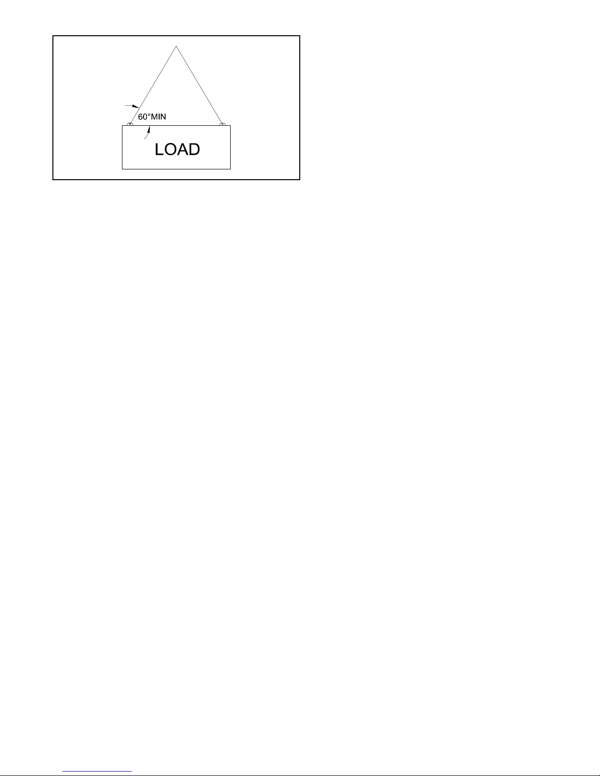
A. Lifting and Rigging
Use of a spreader beam is preferred but not
mandatory. An approved, inspected, and rated
sling suitable for the total published boiler
weight shall be used. The correct WLL (working
load limit) shall be calculated based on the
sling angle used, and the WLL must not exceed
the sling rated capacity. The sling angle (angle
between the sling and the load) must not be
less than 60 deg. The boiler must be lifted as
level as practical (less than 5 degree tilt). Refer
to the boiler submittal drawing for dry boiler
weight.
8
Page 9
The unit should be located in the boiler room
so as to provide ease of venting and adequate
clearance for maintenance, serviceability and
installation of piping.
The tube pull space listed in the Burnham
Commercial product catalog must be provided
at the front of the boiler. The coil pull space must
be maintained at the front of units equipped with
tankless coils. Floor construction should have
adequate load bearing characteristics to bear
the weight of the boiler lled with water. A boiler
foundation is recommended if the boiler room
oor is weak, uneven or if a water condition
exists. These boilers are not for installation on
combustible ooring.
B. Installation Clearance
Minimum clearances to combustible walls shall
be as follows:
1. Models 4FH-63A thru 180: 6" sides, rear and
above
2. Models 4FH-209A thru 3075A: 18" sides, rear,
and above
3. Minimum recommended service clearances:
18".
See boiler submittal drawings for tube pull
clearance requirements.
If desiccant package was ordered, be sure
to remove from the boiler furnace using the
rear access, and from the waterside using the
manhole cover.
4. FLUE OUTLET, STACK, AND BREECHING
The maximum weight limit on the boiler ue outlets
is as follows:
1. Series 4FH: 250 lb
2. All stack/economizer weights exceeding the limits
above will need to be independently supported.
Stack design: The stacks shall be installed in
compliance with NFPA 54, ANSI Standard
Z223.1, state and local codes, using a category
III product for positive, non-condensing
appliances. The boiler ue outlets are generally
sized for the correct stack diameter, but there
are exceptions to this.
The 4FH Series boilers are equipped with a ue
outlet stub to accept a slip-on stack connection.
The boilers are optimally designed to run with a ue
outlet pressure of .10-.30”wc pressure. The stack
design, taking into account the draft effect and all
friction losses, should arrive at 0.0"wc +/- .10"wc
pressure at the inlet. Horizontal runs should be kept
to a minimum. This will ensure the boiler will meet
the maximum capacity, and will light off and have
stable and consistent combustion.
On installations where a natural draft stack is used,
causing high breeching drafts, the boiler locking
blade damper (on boilers equipped with one) may
require adjusting, or one may need to be installed at
the boiler breeching. In multiple boiler installations,
or in installations where the breeching draft may vary
considerably, automatic draft controls in combination
with a motorized damper may be required.
5. COMBUSTION AIR REQUIREMENTS
All boiler rooms must be adequately vented to
provide enough combustion air to the boiler for proper
tuning and operation, to prevent oxygen depletion,
possible carbon monoxide formation, possible
accumulation of fuel fumes, and possible equipment
explosions. A free ow of combustion air will aid the
proper operation of the burner and allow for proper
venting of the boiler. The instructions below must be
followed to properly size make-up air openings in the
boiler room. Consult NFPA-54 National Fuel Gas Code,
NFPA-31 Installation of Oil Burning Equipment for more
detailed explanations, and local codes for additional
guidance for boiler rooms below grade and other
specic situations.
Two general methods may be used:
1. When one permanent opening is used: The
opening shall commence within 12" of the top
of the enclosure (boiler room) and the opening
shall communicate directly with the outdoors,
or through a vertical or horizontal duct with the
outdoors. The opening shall have a minimum
free area of 1 sq in per 3,000 BTU/hr total input
of all equipment in the enclosure, and not less
than the sum of the areas of all equipment vent
connectors.
2. When two permanent openings are used: One
opening location shall begin within 12" of the
top of the enclosure, and the other opening
location shall begin within 12" of the bottom of
the enclosure. When communication is directly
with the outdoors, or through vertical ducts, each
opening shall have a minimum free area of 1 sq
in per 4,000 BTU/hr total input of all equipment
in the enclosure. Where communicating with the
outdoors through horizontal ducts, each opening
shall have a minimum free area of 1 sq in per
2,000 BTU/hr total input of all equipment in the
enclosure.
9
Page 10

Duct size, if used, shall have a minimal cross
sectional area equal to the opening size.
Outside air openings may be protected by mesh,
grills, or louvers. When doing so, the free area sizing
must be compensated for the blocking effect of such
obstructions. Protective mesh must be no smaller
than 1/4". If the free area of the grilles and louvers
is unknown, use 20-25% free area for wood louvers,
and use 60-75% free area for metal louvers and
grilles.
Closeable louvers must be electrically interlocked
with the burner to prevent the burner from ring if the
louvers fail to open or remain open.
The boiler room should not be under negative
pressure at any time.
Adjustment to air opening and duct size shall be
made to boilers at higher altitude installations (above
1,000 ft). An adjustment of 3.5% per 1,000 ft of
elevation is recommended.
7. NORMAL BOILER WATER LEVEL
The normal boiler water level is the water height
where the steam boiler water level should operate at. If
using an on/off pump control, this will correspond with
the “pump-off” level. The following dimensions represent
the vertical distance from the reference point to the
Normal Water Level.
Series 4FH Firebox – Reference point is from the top of
the boiler base
4FHL-63A/107A 40-3/4"
4FHL-127A/209A 48-1/2"
4FHL-240A/345A 55"
4FHL-360A/450A 66-3/16"
4FHL-563A/675A 69"
4FHL-827/993 74"
4FHL-1157/1323 85-1/2"
4FHL-1654 100-1/4"
4FHL-1985/2645 114-1/4"
4FHL-3075A 122-1/2"
6. LOCATION OF ASME STAMPING DATA
The ASME stamping data is located as follows:
1. Series 4FH: Sizes 63 thru 675, on the left side of
the boiler shell near the front, under a 3 x 6 cover
plate. Sizes 827 thru 3075, on the right side front
tubesheet.
10
Page 11

SECTION II — INSTALLATION INSTRUCTIONS
1. BOILER PIPING
A. Water Boiler
Attach supply and return piping lines and insert
plugs and bushings in connections as required.
Supply and return piping headers are detailed in
Figure 2.
It is important to comply with the minimum piping
requirements in order to ensure maximum performance
and reliability on steam boilers, particular attention should
be given to the construction of the supply header.
Il est important de respecter les exigences minimales en
matière de tuyauterie pour assurer une efcacité et une
abilité optimales des chaudières à vapeur, en portant
une attention particulière à l’assemblage du collecteur
d’alimentation.
The nominal temperature differential between supply and
return water recommended for Burnham retube water
boilers is 20°F. As a precaution against thermal shock,
this differential should never exceed 40°F.
When differentials in excess of 30°F are anticipated on
rebox boilers, the return water should enter the boiler at
the top tting (normally the supply) and the supply water
should leave the boiler through the bottom tting (normally
the return). This ow pattern directs the return water over
the relatively cool third pass rather than directly against
the rear of the furnace.
The boiler should not be operated for any length of time
at a temperature setting that allows the formation of
condensation in the tubes or smokebox. This generally
dictates a minimum setting of approximately 140°F on
the low limit on systems with a 20°F system differential.
On cold start up, condensation can be expected until the
boiler warms up. If formation of condensate persists, the
low limit should be adjusted upward until condensate no
longer forms.
Water boilers and low pressure steam boilers must have
a set LFH at 120° minimum to avoid condensation. High
pressure steam should have a minimum LFH temperature
of 180°F.
L’écart de température nominale de l’eau d’alimentation
et de l’eau de retour recommandé pour les chaudières
ignitubulaires Burnham est de 11° C (20°F). An de prévenir
un choc thermique, cet écart ne devrait jamais dépasser
22°C (40°F).
Lorsque des écarts supérieurs à 17°C (30°F) sont prévus
sur une chaudière à foyer intérieur, l’eau de retour devrait
entrer par le raccord du haut (l’alimentation), et l’eau
d’alimentation devrait sortir par le raccord du bas (le
retour). Ce schéma de circulation dirige l’eau de retour
vers le troisième passage, plus tempéré, plutôt que vers
l’arrière directement.
La chaudière ne devrait fonctionner en aucun moment à
une température favorisant la formation de condensation
dans les tubes ou la boîte à fumée. Cette obligation
force généralement un réglage minimal d’environ 600°C
(140°F) comme limite inférieure sur les systèmes dont
l’écart nominal est de 11°C (20°F). Lors d’un démarrage
à froid, un effet de condensation est à prévoir jusqu’à
ce que la chaudière se réchauffe. Si la formation de
condensat persiste, la limite inférieure de température
doit être ajustée à la hausse jusqu’à ce qu’il n’y ait plus
de condensation.
Les chaudières à eau et les chaudières à vapeur basse
pression doivent avoir une température à faible risque
d’incendie (LFH) paramétrée à un minimum de 67°C
(120°F) an d’éviter la condensation. Les chaudières à
vapeur haute pression doivent avoir une température LFH
minimale de 100°C (180°F).
11
Page 12

Flow Rate Based On Delta-T
APPROXIMATE BOILER WATER FLOW
RATE REQUIRED (GPM) – SERIES 4FH
BOILER SIZE
(bhp)
63A 43 29 22
78A 53 36 27
92A 63 42 31
107A 73 49 37
127A 87 58 44
154A 106 71 53
180A 124 83 62
209A 144 96 72
240A 166 111 83
277A 192 128 96
311A 216 144 108
345A 241 161 120
360A 251 168 126
450A 317 211 158
563A 400 267 200
675A 483 322 242
827 591 394 295
993 708 472 354
1157 823 549 411
1323 939 626 469
1654 1166 777 583
1985 1399 933 700
2315 1638 1092 819
2645 1878 1252 939
3075A 2186 1457 1093
20º Delta T 30º Delta T 40º Delta T
Boiler Waterside Pressure Drop
Due to the large internal water reservoir and
a design having very little ow restriction, the
waterside ow pressure drop is less than 1 psi.
This is applicable to all ow rates, including the
highest ow rate corresponding with a 20ºF delta T.
B. Steam Supply Connection & Piping
Most steam boilers are supplied with a anged
steam outlet connection, with the exception of the
smallest boilers, which may have a threaded pipe
connection. All low pressure steam boilers (15
psig) are supplied with a class 150 anged steam
connection. All high pressure steam boilers (over
15 psig) are supplied with a class 300 anged
steam connection.
changes within the boiler can create stresses
in the boiler metal. These stresses can cause
damage to the boiler by loosening tubes, or
in more severe instances can crack tube sheet
ligaments,furnaces, or waterlegs.
B. If temperature differentials approach 40°F,
to help prevent temperature uctuations and
insure proper circulation through the boiler, a
recirculation loop as shown in Figure 3 should be
considered. The recirculation ow should be at
least 1/2 GPM/BHP at all times when the boiler is
online for operation.
3. TANKLESS HEATER
Install an automatic mixing valve at the tankless heater
outlet to avoid risk of burns or scalding due to excessively
hot water at the xtures. Adjust and maintain the mixing
valve in accordance with the manufacturer’s instructions.
Installer une vanne mélangeuse automatique au chauffeeau sans réservoir pour éviter les risques de brûlure
causés par une température excessive de l’eau dans la
plomberie. Ajuster la vanne mélangeuse conformément
aux instructions du fabricant, et la maintenir ainsi.
A. If boiler is ordered with tankless heater, connect
tankless heater piping as shown in Figure 2.
B. The following guidelines should be followed when
piping the tankless heaters:
4. FLOW REGULATION
If ow through the heater is greater than its rating,
the supply of adequate hot water may not be able to keep up
with the demand. For this reason a ow regulator matching
the heater rating should be installed in the cold water line to
the heater. The ow regulator should preferably be located
below the inlet so it's not subjected to excess temperatures
that may occur during “off” periods when it is possible for
the heat to be conducted back through the supply line. The
ow regulator also limits the ow of supply water regardless
of inlet pressure variations in the range of 20 to 120 psi.
2. RECOMMENDED WATER BOILER
RECIRCULATION LOOP
The following guidelines relating to system water
temperature uctuation and ow through the boiler
must be observed.
A. It is important to operate your boiler in such a
manner as to prevent temperature uctuation of
more then 40°F at any time. Rapid temperature
12
Page 13

FIGURE 2
SCHEMATIC TANKLESS HEATER PIPING
5. TEMPERING OF HOT WATER
Installation of an automatic mixing valve will
lengthen the delivery of the available hot water by mixing
some cold water with the hot. This prevents excessive
and possibly scalding hot water. Higher temperature hot
water is possible by piping the hot water from the heater
prior to entering the mixing valve. The mixing valve
should be “trapped” by installing it below the cold water
inlet to heater to prevent lime formation in the valve.
6. FLUSHING THE BOILER
All water contains some sediment which settles on
the inside of the coil. Consequently, the heater should
be periodically backwashed. This is accomplished by
installing hose bibs as illustrated and allowing water at
city pressure to run into hosebib A, through the heater,
and out hosebib B until the discharge is clear. The tees
in which the hosebibs are located should be the same
size as heater connections to minimize pressure drop.
rating plates), must meet or exceed the minimum
required relieving capacity as stamped on the boiler
rating plate.
Install the valve(s) in the ttings supplied on the top
of the boiler using appropriate pipe dope. In some cases,
reducing bushings are required to adapt the relief valve
inlet to the boiler tting. When required, the bushings are
supplied by Burnham. Using the bushings is NOT a code
violation. Always install the relief valves in the vertical
position with no intervening valve.
Pipe the relief valve to a safe point of discharge, with
same pipe size as the valve outlet connection – never
reduce. The discharge piping shall be arranged as short
as possible, and properly supported to prevent stresses
on the relief valve. Never install a valve or plug on the
relief valve outlet piping.
A method of gravity drain must be employed in the
discharge pipe at or near each relief valve and where
condensate may collect. Where a vertical discharge pipe
is used, a drip pan elbow is highly recommended.
10. BOTTOM BLOWDOWN PIPING
See suggested piping schematics for bottom
blowdown piping. The bottom blowdown connection on
the boiler has been properly sized according to ASME
Code. DO NOT reduce the blowdown piping size from
the boiler connection to the point of discharge. Do not
use galvanized pipe or ttings.
Valve ratings:
For ASME Section IV low pressure steam (15 psig)
and water boilers, the valve pressure rating shall meet
or exceed the boiler MAWP rating, as stamped on the
boiler, but in no case less than 30 psig. The minimum
temperature rating of the valves shall be 250F.
7. HARD WATER
May be applicable to some city and particularly well
water. Have your water analyzed by a qualied water
treatment specialist to determine if a water softener,
conditioner or ltration is required. Treated water will
ensure longer tankless heater life and performance
and is also benecial to all the piping and xtures in
the building.
8. FUEL SUPPLY PIPING
For information regarding gas supply line piping
schematic and sizing, drip leg, gas pressure regulator,
oil supply line piping schematic and sizing, oil pump,
and oil lter, please refer to the BURNER
INSTALLATION AND OPERATION MANUAL.
9. RELIEF VALVES
Boiler relief valves are normally shipped loose and
have been properly sized for your boiler. The aggregate
capacity of the relief valves (as stamped on the valve
13
Page 14

INSTALLATION INSTRUCTIONS
FIGURE 3
TS-71-176-B
14
FIGURE 4
TS-71-130-D
Page 15

INSTALLATION INSTRUCTIONS
FIGURE 5
TS-3-101-4
FIGURE 6
TS-71-131-D
15
Page 16

SECTION III — OPERATING INSTRUCTIONS
1. ALWAYS INSPECT INSTALLATION BEFORE
STARTING BURNER.
2. FILL HEATING SYSTEM WITH WATER.
Any time that raw water is introduced to the boiler
it must be heated to at least 180ºF immediately to
dissipate the dissolved gases which can otherwise
cause internal corrosion to the boiler.
Chaque fois que de l’eau non traitée est introduite
dans la chaudière, il faut immédiatement la chauffer
jusqu’à 100°C (180°F) pour dissiper les gaz dissous qui,
autrement, pourraient provoquer de la corrosion interne.
A. Steam Boilers Fill boiler to normal water line.
Water should be visible in the gauge glass.
After boiler is in operation, make up water should
be added slowly to maintain the water level.
B. Hot Water Boilers In a hot water heating
system, the boiler and the entire system
(other than the tank) must be full of water for
satisfactory operation. Water should be added
to the system until the boiler pressure gauge
registers normal system design operating
pressure. To ensure that the system is full, water
should come out of all air vents when opened.
ON A HOT WATER SYSTEM THE PRESSURE MUST
NOT EXCEED 30 POUNDS UNLESS THE BOILER IS
ESPECIALLY DESIGNED FOR A HIGHER MAXIMUM
WORKING PRESSURE. IF A BOILER PRESSURE EXCEEDS
PRESSURE SETTING OF SAFETY RELIEF VALVE, VALVE
WILL RELIEVE IMMEDIATELY, BUT CAUSE OF RELIEF
MUST BE INVESTIGATED AND CORRECTED. EXCESS
PRESSURE IS DANGEROUS, IN ADDITION, COULD CAUSE
DAMAGE TO HEATING SYSTEM, PERSONAL INJURY OR
SERIOUS PROPERTY DAMAGE.
DO NOT draw water from the boiler while in use. When
adding water while boiler is in operation, do not open
the supply valve fully, but add water slowly.
LES SYSTÈMES À EAU CHAUDE NE DOIVENT PAS
ÊTRE SOUMIS À UNE PRESSION DÉPASSANT
30 LIVRES, À MOINS QUE LA CHAUDIÈRE SOIT
CONÇUE SPÉCIALEMENT POUR UNE PRESSION
DE FONCTIONNEMENT PLUS ÉLEVÉE. SI LA
PRESSION INTERNE DE LA CHAUDIÈRE DÉPASSE
LA PRESSION PARAMÉTRÉE DE LA SOUPAPE DE
SÛRETÉ, CETTE DERNIÈRE RELÂCHERA DE LA
PRESSION IMMÉDIATEMENT, MAIS LA CAUSE DE
CETTE DÉCOMPRESSION DOIT ÊTRE EXAMINÉE
ET CORRIGÉE. LA PRESSION EXCESSIVE EST
DANGEREUSE. DE PLUS, ELLE POURRAIT
ENDOMMAGER LE SYSTÈME DE CHAUFFAGE OU
CAUSER DES BLESSURES OU DES DOMMAGES
MATÉRIELS SÉRIEUX.
NE PAS soutirer de l’eau de la chaudière lorsque
celle-ci est en marche. Si la chaudière fonctionne, ne
pas y ajouter de l’eau en ouvrant complètement la vanne
d’alimentation; ajouter l’eau lentement.
3. BURNER
A. Check wiring of all fuel valves. Verify that wiring
is correct according to the factory supplied wiring
diagram.
B. Leave all manual fuel valves closed. This includes
manual shutoff valves supplied with the boiler and
facility installed valves at the boiler site.
C. Perform all burner pre-startup checks according
to the burner manufacturer's specications. Refer
to the burner manufacturer's installation manual
furnished with the boiler.
D. Turn boiler on and verify that fuel valves are
closed during the burner pre-purge cycle. Turn
boiler off and disconnect power.
E. Adjust burner according to the burner
manufacturer's specications. Target CO2 level
is 13% for optimum efciency, but a range of
12.5-13.0% is acceptable.
4. TEST CONTROLS
Before installation of the boiler is considered complete
the operation of the boiler controls should be checked,
particularly the low water cutoff and the high limit
control.
16
Avant que l’installation de la chaudière soit considérée
comme terminée, vérier le fonctionnement de ses
dispositifs de contrôle, en particulier les interrupteurs
à bas niveau d’eau et le contrôleur de température
maximale.
Page 17

A. Check Operating Control Raise and lower
operating control setting as required to start and
stop burner.
B. Warning Check High Limit Control
Jumper Operating Control Terminals. Allow
Burner to operate until shut down by limit.
Installation is not considered complete until this
check has been made. REMOVE JUMPER.
C. Check Low Water Cut-Off control with water
level at normal waterline. Raise operating control
setting to allow burner to operate. Open boiler
drain to allow water level to drop until burner
operation is shut down by low water cutoff.
DO NOT ALLOW THE BOILER TO OPERATE BELOW THE
MINIMUM PERMISSIBLE WATER LEVEL AS INDICATED
ON THE BOILER.
NE PAS LAISSER LA CHAUDIÈRE FONCTIONNER
LORSQUE LE NIVEAU D’EAU EST PLUS BAS QUE LE
SEUIL INDIQUÉ SUR LA CHAUDIÈRE.
Close boiler drain and rell to normal water line.
Unless boiler is equipped with a manual reset low water
cutoff, burner should automatically restart during ll.
Reset operating control.
PROBE AND FLOAT TYPE LOW WATER CUT-OFF
DEVICES REQUIRE ANNUAL INSPECTION AND
MAINTENANCE. Refer to Service Instructions,
Section IV for proper cleaning instructions.
LES INTERRUPTEURS À BAS NIVEAU D’EAU DE
TYPE SONDE ET DE TYPE FLOTTEUR DOIVENT ÊTRE
INSPECTÉS ET ENTRETENUS ANNUELLEMENT. Se
reporter aux directives sur l’entretien, à la section IV,
pour connaître les directives de nettoyage adéquat.
D. Check Operating Control on boiler equipped
with a tankless heater. With burner off, draw hot
water until burner starts, then turn off hot water
and check burner shut down.
5. CLEANING A NEW STEAM BOILER
Oil, grease & sediments which accumulate in a new
boiler and piping must be removed from the system in
order to prevent an unsteady water line and carryover of
the water into the supply main above the boiler. Operate
the boiler with steam in the entire system for a few days
allowing the condensate to return to the boiler. If the
condensate can temporarily be wasted, operate the
boiler only for the length of time it takes for condensate
to run clear. If the latter cannot be achieved or if the
condensate is returned to the boiler, boil out the boiler
using the SURFACE BLOWOFF connection on the
boilers so equipped.
A. Drain boiler until water is just visible in gauge
glass. Run temporary pipe line from the surface
blow-off to an open drain or some other location
where hot water may be discharged safely.
Do not install valve in this line.
Certain state and local codes may restrict
the use of some chemicals listed for cleaning
and maintaining the boiler. Check with local
authorities before proceeding with the use of
any chemicals.
B. Drain about 5 gallons of hot water from boiler into
a container and dissolve into it 1 pound o caustic
soda and one pound of trisodium phosphate
for each 50 gallons of boiler water. Additional
containers may be required to dissolve sufcient
chemicals for large models. Remove safety valve
and add solution to boiler water through exposed
tapping.
Use extreme care in handling these chemicals.
Caustic soda is harmful to skin, clothing and
eyes. Do not permit the dry material or the
concentrated solution to come into contact with
the skin or clothing.
C. Close all valves leading to and from the system to
isolate the cleaning solution from the system.
D. Start Burner and operate sufciently to boil the
water without producing steam pressure. Boil for
about 5 hours. Open boiler feed pipe sufciently
to permit a steady trickle of water from the
surface blowoff pipe. Continue this slow boiling
and trickle of overow for several hours until the
water coming from the overow is clear.
E. Stop burner and drain boiler in a manner and
location that hot water can be discharged safety.
F. When the boiler has cooled to 120°F or less rell
boiler to normal water line. If water in gauge glass
does not appear to be clear, repeat steps A thru
E, boiling out the boiler for a longer time.
G. Remove temporary piping, plug tapping and/or
reinstall safety valve. Boil to bring water
temperature to 180ºF promptly in order to drive
off any dissolved gases in the fresh water.
6. CLEANING A WATER BOILER
The oil and grease which accumulate in a new hot
water boiler can be washed out in the following manner.
A. Remove safety relief valve using extreme care to
avoid damaging it.
17
Page 18

Certain state and local codes may restrict the use of some
chemicals listed for cleaning and maintaining the boiler.
Check with local authorities before proceeding with the
use of any chemicals.
L’utilisation de certains des produits chimiques indiqués
pour le nettoyage et l’entretien de la chaudière peut être
restreinte par les codes municipaux ou provinciaux. Il
convient de s’informer auprès des autorités locales avant
de procéder à l’utilisation de tout produit chimique.
B. Drain about 5 gallons of hot water from boiler
into a container and dissolve into it 1 pound of
caustic soda and one pound of trisodium
phosphate for each 50 gallons of boiler water.
C. Add solution through exposed tapping, and
reinstall safety valve.
D. Fill the entire system with water.
E. Start ring the boiler.
F. Circulate the water though the entire system.
G. Vent the system, including the radiation.
H. Allow boiler water to reach operating
temperature, if possible.
I. Continue to circulate the water for a few hours.
J. Stop ring the boiler.
K. Drain the system in a manner and to a location
that hot water can be discharged safely.
L. When the boiler has cooled down to 120°F or
less, remove plugs from all available returns and
wash the water side of the boiler as thoroughly as
possible, using a high-pressure water stream.
M. Rell the system with fresh water, and bring
water temperature to 180°F promptly in order to
drive off any dissolved gases.
7. WATER BOILER OPERATION
The following guidelines relating to system water
temperature uctuation and ow through boiler must be
observed.
A. It is important to operate your boiler in such a
manner as to prevent temperature uctuation of
more than 40°F at any time. Rapid temperature
changes within the boiler can create stresses in
the boiler metal. These stresses can cause
damage to the boiler by loosening tubes, or in
more severe instances can crack tube sheet
ligaments, furnaces, or waterlegs.
B. It is equally important to insure that there is
circulation through the boiler of at least 1/2 GPM/
BHP at all times when the boiler is ring.
8. BOILER WATER TREATMENT
Boiler water treatment will help maximize the
effectiveness and prolong the life of pressure
vessels.
The general objectives of boiler water
treatment are:
A. Remove corrosive gases from feedwater and
boiler water.
B. Prevent sludge and scale deposits on the water
side heating surfaces.
C. Prevent foaming and carryover.
Consult with a local water treatment company regularly
engaged in the treatment of boiler water for advice in
maintaining the proper feedwater, boiler water, and
condensate chemistry.
Pour obtenir des conseils sur le maintien d’une composition
chimique adéquate pour l’eau d’alimentation, l’eau de
la chaudière et le condensat, consulter le personnel
d’une station de traitement des eaux locale qui traite
régulièrement des eaux de chaudière.
Certain state and local codes may restrict the use of
some chemicals listed for cleaning and maintaining
the boiler. Check with local authorities before
proceeding with the use of any chemicals.
9. MAKE PH OR ALKALINITY TEST
After boiler and system have been cleaned and
relled as previously described, test the pH of the water
in the system. This can easily be done by drawing a
small sample of boiler water and testing with hydrion
paper which is used in the same manner as litmus
paper, except it gives exact readings. A small color chart
on the side of the hydrion dispenser gives the reading
in pH. Hydrion paper is inexpensive and obtainable
from any chemical supply house or through your local
druggist. The pH should be higher than 8.3 but lower
than 10.5. Add some washout chemical (caustic soda), if
necessary, to bring the pH within the specied range.
10. FREQUENT WATER ADDITION
If, during normal operation, it is necessary to add water
more frequently than once a month, consult a qualied
service technician to check your system for leaks.
S’il est nécessaire d’ajouter de l’eau plus d’une fois par
mois à une chaudière utilisée normalement, consulter un
technicien d’entretien qualié an de vérier la présence
de fuites dans votre système.
A leaky system will increase the volume of make-up
water supplied to the boiler which can signicantly
shorten the life of the boiler. Entrained in make-up water
are dissolved minerals and oxygen. When the fresh,
cool make-up water is heated in the boiler the minerals
18
Page 19

fall out as sediment and the oxygen escapes as a gas.
Both can result in reduced boiler life. The accumulation
of sediment can eventually isolate the water from
contacting the cast iron. When this happens the cast
iron in that area gets extremely hot and eventually
cracks. The presence of free oxygen in the boiler creates
a corrosive atmosphere which, if the concentration
becomes high enough, can corrode the cast iron through
from the waterside. Since neither of these failure types
are the result of a casting defect the warranty does not
apply. Clearly it is in everyone’s best interest to prevent
this type of failure. The maintenance of system integrity
is the best method to achieve less makeup water.
Oxygen contamination of the boiler water will cause
corrosion of iron and steel boiler components, and can
lead to boiler failure. Burnham’s standard warranty does
not cover problems caused by oxygen contamination of
boiler water or scale (lime) build-up caused by frequent
water addition or by improper water chemistry as shown
below.
Une contamination de l’eau de la chaudière par l’oxygène
provoque la corrosion des composants en fer et en acier,
et peut mener à une défaillance. La garantie standard
de Burnham ne couvre pas les problèmes causés par
la contamination de l’eau de la chaudière par l’oxygène
ou l’accumulation de tartre (calcaire) qui découlent de
l’ajout fréquent d’eau ou d’une composition chimique
inadéquate comme illustré ci-dessous.
In order to ensure long product life, oxygen sources
should be eliminated. This can be accomplished by
taking the following measures:
A. Repairing system leaks to eliminate the need for
addition of make-up water.
B. Eliminating open tanks from the system.
C. Eliminating and/or repairing ttings which allow
oxygen absorption.
D. Use of non-permeable materials in the distribution
system.
E. Isolating the boiler from the system water by
installing a heat exchanger.
Minimum Water Quality Requirements
pH - 8.3 - 10.5
TDS - 3500 ppm
Total alkalinity ppm as CaCO
Total copper ppm - .05
Oily matter ppm -1
total harness ppm -3 Chlorides - < 50 ppm
There are many possible causes of oxygen
contamination such as:
A. Addition of excessive make-up water as a result
of system leaks.
B. Absorption through open tanks and ttings.
C. Oxygen permeable materials in the distribution
system.
D. Suction at pump and valve seals.
- 1200
3
19
Page 20

SECTION IV — SERVICE INSTRUCTIONS
See item 10 under Operating Instruction if it becomes
necessary to add water to the boiler more frequently
than once a month.
Se reporter à l’article 10 dans la section Instructions
de fonctionnement si le remplissage de la chaudière
devient nécessaire plus d’une fois par mois.
1. GENERAL
Inspection should be conducted annually. Service
as frequently as specied in paragraphs below. Before
service or maintenance is performed complete boiler
shutdown/cooldown procedure.
2. BOILER SHUT DOWN AND COOLDOWN
PROCEDURE
NOTE: This procedure is generally required in
preparation for corrective or preventative maintenance
in the unit. This procedure must be supervised by an
individual who is thoroughly qualied in operation and
maintenance of the equipment at hand. This is written
with Steam Boilers in mind, but the principles are
applicable to Hot Water Boilers as well.
A. Decrease plant load as much as possible.
B. Turn boiler switch off. If control power from
burner is used to support accessories, leave
on until boiler system has cooled down.
C. Shut and lock manual gas and oil valves as
applicable.
D. In single boiler installations, some small steam
loads can remain on to assist in a controlled
cooldown of the boiler (i.e., deaerator). In multiple
boiler installations, shut down the non-return
valve and the back up valve. Lock them shut.
E. Allow the boiler feed pump to remain active. As
the boiler cools down, the water level is reduced
by demand or shrinkage. It is best to be aware of
the boiler level at all times.
F. When boiler pressure has decreased to 5 to
10 psi on the pressure gauge, open the boiler
manual vent valve on the top of the boiler. This
is to act as a sentinel against the increase in
pressure and to prevent the boiler from going into
a vacuum. Lock the valve open.
NOTE: Depending on the size of the boiler, the large
mass of heating surfaces that are still hot can cause the
boiler water temperature to increase, even if the gauge
pressure is “0”. It is better to allow the entire system to
cool gradually, never force cool the boiler as damage
can also be inicted due to “thermal shock.”
G. When boiler and water are below 120°F, shut off
power to the unit and lock out the circuit
breakers.
H. If required, open front and rear doors for
3. CLEAN THE BOILER HEATING SURFACES
AND FLUE
At least once each year, preferably at the end of the
heating season.
Remove all accumulations of soot with a wire
brush and vacuum. Remove all obstructions. Replace
deteriorated parts and support properly. Seal all joints.
observation of reside surfaces.
I. Drain boiler down as far as required. (Usually
completely.) Make sure the vent valve on the top
of the boiler remains open. Open and lock the
oat control low water cutoff drain valves. These
will serve as additional vents.
J. Shut and lock the boiler feed valves, and any
blowdown valves that can be affected by other
boilers in the same facility (i.e., bottom blow down
valves can tie into a common blowdown
separator in a multiple boiler installation).
K. If necessary to remove handhole and/or manhole
plates for water side inspection or maintenance,
use extreme caution. Loosen the nuts securing
the arch enough to allow the plate to drop
approximately 1/8 inch when tapped loose with
a mallet. Once again, ensure the pressure in the
boiler is “0” before loosening the plate. Remove
the plate the remainder of the way. Wear gloves
and eye protection at all times.
A. Clean the Vent System
Vent system should be checked annually for:
1. Obstructions.
2. Accumulations of soot.
3. Deterioration of vent pipe or vent accessories
due to condensation or other reasons.
4. Proper support no sags, particularly in
horizontal runs.
5. Tightness of joints.
B. Clean the Boiler Heating Surfaces
At the end of the heating season, clean boiler
heating surfaces thoroughly. Access to boiler
retubes may be gained by removing the front
and rear smokeboxes or smokebox doors.
Where applicable, remove the turbulators, paying
close attention to which tubes have turbulators.
20
Page 21

Clean retubes with ue brush and reinstall
turbulators. If turbulators are corroded or
deteriorated, replacing them will ensure a high
level of boiler efciency. Remove soot and rust
and reseal the boiler.
Turbulator quantities are shown below. Access to
turbulator replacement is from the front smokebox.
Turbulators should be installed and removed from
the front of the boiler only.
Series 4FH: All 4FH Series boilers come equipped
with turbulators in all third pass tubes (upper rows
of tubes), with quantities as follows:
1. Sizes 63A/107A quantity of (18).
2. Sizes 127A/209A quantity of (22).
3. Sizes 240A/345A quantity of (40).
4. Sizes 360A/450A quantity of (46).
5. Sizes 563A/675A quantity of (56).
6. Sizes 827/993 quantity of (54).
7. Sizes 1157/1323 quantity of (72).
8. Size 1654 quantity of (93).
9. Size 1985/2315 quantity of (109).
10. Size 2645 quantity of 113.
11. Size 3075A quantity of (151).
4. BOTTOM BLOWDOWN PROCEDURE
Burnham high pressure steam boilers are equipped
with two bottom blowdown connections. Bottom
blowdown should be done while the boilers are under
pressure, with the burner off or at low re. There should
be two quick-opening valves and one downstream
slow-opening valve. Open the slow-opening valve rst.
Slowly open the front quick-opening valve to warm up
the piping and blowdown separator. Open the valve for
a few seconds with a quick blast to ush out sludge and
sediment from the bottom of the boiler. Do not lower the
boiler water level by more than ½". Close the valve, then
repeat for the rear quick-opening valve. Close the slowopening valve. Make sure all valves are closed. A water
treatment consultant can recommend an appropriate
manual blowdown schedule, but is generally done once
per shift.
Water columns should be blown down once per shift to
keep the internal parts of the pump control and low water
cutoff free from sediment. If the boiler is equipped with a
“water column bypass” switch, depress the switch while
performing the blowdown. Close the valve and release
the switch.
5. MAINTENANCE OF LOW WATER CUTOFF
DEVICES
Probe and oat type low water cutoff devices require annual
inspection and maintenance.
Les interrupteurs à bas niveau d’eau de type sonde ou
de type otteur doivent être inspectés et entretenus
annuellement.
A. Probe Type Low Water Cut Off Although these
devices are solid state in design, the probe is
exposed to possible contamination in the boiler
water.
It is important to physically remove the probe
from the boiler tapping annually and inspect it for
accumulation of scale or sediment.
Following these steps inspect, clean and/or
replace the probe:
1. Turn off electric service to the boiler.
2. Drain boiler water to a level below the tapping
for the probe.
3. Disconnect the wiring connections between
the low water cutoff and the probe.
4. Dismount the low water cutoff control from the
probe.
5. Unscrew the probe from the boiler tapping.
6. Inspect that portion of the probe that is
exposed to the boiler water for scale or
sediment buildup.
7. Light deposits may be removed by wiping the
probe with a damp cloth. Wiping the probe
with a cloth soaked in vinegar will remove
more tenacious lime deposits. The most
stubborn deposits may be removed from the
probe by using diluted amount (3 part of water
to 1 part) of phosphoric acid (H2PO4).
21
Page 22

Exercise caution when handling phosphoric acid and
follow the instruction label on its container.
Faire preuve de prudence lors de la manipulation
d’acide phosphorique et suivre les directives qui se
trouvent sur l’étiquette du contenant.
8. Wire brushing of the probe is not
recommended.
9. Clean the pipe threads of the probe to remove
old, hardened pipe dope and other foreign
matter.
10. Apply a moderate amount of good quality pipe
dope to the pipe threads on the probe, leaving
the rst two threads bare. Do not use PTFE
(Teon) tape.
11. Screw the probe into the boiler tapping.
12. Mount the low water cutoff control on the
probe.
13. Reconnect the control to probe wiring.
14. Fill the boiler to its normal waterline.
15. Add boiler water treatment compound as
needed (see Section III Item 8).
16. Restore electric service to boiler.
17. Fire burner to raise water temperature to
above 180°F to drive off free oxygen.
when this type of control is used. Check the oat for
evidence of collapse and check mercury bulb (where
applicable) for mercury separation or discoloration.
DO NOT ATTEMPT TO REPAIR MECHANISM IN THE
FIELD. Complete replacement mechanisms, including
necessary gaskets and installation instructions, are
available from the manufacturer.
6 SURFACE BLOWDOWN PROCEDURE
The purpose of the Surface Blowoff connection is to
provide a means to remove impurities that collect near
the surface of the water level on steam boilers, and to
bleed off a small portion of the boiler water to lower the
level of TDS (total dissolved solids). This will decrease
boiler foaming and improve steam quality.
The following Surface Blowoff connections are
provided as standard:
A. Series 4FH: Sizes 63 thru 345, (1) tting left side
of boiler, sizes 360 thru 3075, (1) tting right side
of boiler.
B. The amount and frequency of surface blowoff is
based on the amount of TDS you are targeting,
the amount of make-up water, and the amount
of TDS in the make-up water. The following is an
example for a 250hp steam boiler:
1. Approximate evaporating rate at full capacity:
250 bhp x 34.5 = 8625 lb/hr
2. Make-up water (i.e. 20%): 1725 lb/hr
BEFORE RETURNING BOILER TO SERVICE: Follow the
low water cutoff check out procedure in Section III Item
4 Part C.
AVANT DE RETOURNER LA CHAUDIÈRE POUR UN
ENTRETIEN : Suivre la procédure de vérication du
dispositif de coupure du combustible en cas de bas
niveau d’eau de la section III, article 4, partie C.
B. Float Type Low Water Cut-Off During the
heating season, if external low water cutoff is on
the boiler, the blow off valve should be opened
once a month (use greater frequency where
conditions warrant), to ush out the sediment
chamber so the device will be free to function
properly.
Low water cutoffs and water feeders should be
dismantled annually by qualied personnel, to the
extent necessary to insure freedom from obstructions
and proper functioning of the working parts. Inspect
connecting lines to boiler for accumulation of mud, scale,
etc., and clean as required. Examine all visible wiring
for brittle or worn insulation and make sure electrical
contacts are clean and that they function properly. Give
special attention to solder joints on bellows and oat
3. TDS of make-up water (i.e.): 400 ppm
4. Max TDS recommended in the boiler water:
3500 ppm
5. Reduction factor: 3500/400 = 8.75
6. Surface blowoff rate: 1725 / 8.75 = 197 lb/hr x
hr/60 min x gal/8.34 lb = .4 gpm
In this example .4 gpm would be the continuous
blowdown rate to keep the boiler water TDS at 3500
ppm. This is a good starting point and may need ne
adjustment during actual operation.
7. CHECK BURNER AND CONTROLS at least
once a year. See Item 4 under Operating
Instructions for control checks. See Burner Manual for
burner tests and adjustments.
8. LUBRICATE BOILER COMPONENTS according
to manufacturer’s instructions. Generally, this
involves burner and circulator.
9. CHECK SAFETY VALVE at the start of each
heating season and once or twice during the season
to be sure it is in working condition. To do this, fasten
wire or cord to the lever of the valve and pull the lever
standing a safe distance away from the valve.
22
Page 23

10. ATTENTION TO THE BOILER WHILE NOT IN
OPERATION.
If a boiler is not used during the winter months, and it is in a
place subject to freezing, it must be fully drained to prevent
freezing damage.
Si une chaudière est hors fonction durant l’hiver dans un
endroit où la température est sujette à descendre sous le
point de congélation, il convient de la purger entièrement
an de prévenir l’endommagement par le gel.
A. Steam Boilers Procedure for taking steam
boilers off line at the end of heating season:
Drain off boiler water until it runs clear while
holding the boiler temperature between 180
and 200ºF. Then rell to top of gauge glass.
B. Water Boilers Since a water boiler is a
closed system, no draining/relling should be
necessary.
C. Note any time raw water is introduced into the
boiler it must be immediately heated to 180°F
to drive off dissolved gases. If water treatment
is used, sufcient water treatment compound
should be added to condition the make-up
water.
11. REPAIR PARTS
Give boilers series and model number when
ordering repair parts. All repair parts can be ordered
through your local representative or call us at
888-791-3790.
23
Page 24

PERIODIC TESTING RECOMMENDED CHECK LIST
ITEM FREQUENCY ACCOMPLISHED BY REMARKS
Gauges, monitors, and Daily Operator Make visual inspection and
indicators record readings in log
Instrument and equipment Daily Operator Make visual check against
settings recommended specications
Firing rate control Weekly Operator Verify factory settings
Semi-annually Service Technician Verify factory settings
Annually Service Technician Check with combustion test
Igniter Weekly Operator Make visual inspection, check
ame signal strength, if on
display (see "combustion safety
controls)
Fuel Valves
Pilot and Main Weekly Operator Open limit switch - make aural
and visual check - check valve
position indicators and check
fuel meters if so tted
Pilot and Main Annually Service Technician Perform leakage tests - refer to
Gas or Oil burner instructions
Combustion Safety Controls
Flame Failure Weekly Operator If ame display installed, read
and log; for both pilot and main
ames, notify service
organization if readings are
very high, very low or
uctuating; refer to burner
instructions.
Flame Signal Strength Weekly Operator If ame display installed, read
and log; for both pilot and main
ames, notify service
organization if readings are very
high, very low, or uctuating;
refer to burner instructions.
Pilot Turndown Tests As required/ Service Technician Required after any adjustments
Annually to ame scanner mount or pilot
burner; verify annually - refer to
burner instructions
Low Water Fuel Daily/Weekly Operator Refer to control instructions
Cutoff and Alarm Semi-annually Operator Perform a slow drain test in
accordance with ASME Boiler
and Pressure Vessel Code
Section VI
High Limit Safety Control Annually Service Technician Refer to control instructions
Operating Control Annually Service Technician Refer to control instructions
Air Proving Switch Monthly Operator Refer to burner instructions
24
Page 25

PERIODIC TESTING RECOMMENDED CHECK LIST
ITEM FREQUENCY ACCOMPLISHED BY REMARKS
Atomizing Air/Steam Annually Service Technician Refer to burner instructions
High and Low Gas Monthly Operator Refer to burner instructions
Pressure Interlocks
High and Low Oil Monthly Operator Refer to burner instructions
Pressure Interlocks
High and Low Oil Monthly Operator Refer to burner instructions
Temperature Interlocks
Fuel Valve Interlock Annually Service Technician Refer to burner instruction
Switch
Purge Switch Annually Service Technician Refer to burner instructions
Burner Position Interlock Annually Service Technician Refer to burner instructions
Low Fire Start Interlock Annually Service Technician Refer to burner instructions
Automatic Changeover At Least Annually Service Technician Under supervision of gas utility
Control (dual fuel)
Safety Valves As required Operator In accordance with procedure in
Section VI, ASME Boiler and
Pressure Vessel Code,
Recommended Rules for Care
and Operation of Heating
Boilers or Section VII for power
boilers.
Inspect Burner Components Semi-annually Service Technician Refer to burner instructions
Boiler Hydro-Test Annually Service Technician Performed as required, in
accordance with NBIC Part 2,
not to exceed 90% of relief
valve setting.
25
Page 26
26
Page 27

27
Page 28

Commercial Boilers
LIMITED WARRANTY
LIMITED WARRANTY
Subject to the terms and conditions herein, Seller warrants
to the original owner at the original installation site that
products manufactured by Seller (“Products”) comply,
at the time of manufacture, with recognized hydronics
industry regulatory agency standards and requirements
therein effect and will be free from defects in materials and
workmanship for a period of 12 months after the date of
start-up or 18 months after the date of shipment, whichever
shall be less (the “Warranty Period”)
REMEDY
A. The sole remedy for breach of this warranty is
expressly limited to the repair or replacement of any
part found to be defective under conditions of normal
use within the Warranty Period. Installation is not
included.
B. Warranty The owner must notify the original installer
of the Product and Seller (Attention: Burnham
Commercial, PO Box 3939, Lancaster, PA 17604) in
writing, within the Warranty Period, providing a detailed
description of all claimed defects. Transportation to a
factory or other designated facility for repairs of any
products or items alleged defective shall, in all events,
be the responsibility and at the cost of the owner.
E. The suitability of any Product for any particular
application.
F. Any failure resulting from misuse, modication, not
authorized by Seller in writing, improper installation or
lack of proper maintenance.
G. Equipment furnished by the owner, either mounted or
unmounted, or when contracted for by owner to be
installed or handled.
Seller’s liability under this warranty shall not in any case
exceed the amount paid for the Product found defective.
THIRD-PARTY WARRANTIES
For goods or components not manufactured by Seller, the
warranty obligations of Seller shall, in all respects, conform
and be limited to the warranty actually extended to Seller by
its vendors.
SEVERABILITY
To the extent that any provisions of this warranty would be
void or prohibited under applicable law, such provisions
shall be limited in effect to the minimum extent necessary to
render the remaining provisions hereof enforceable.
EXCLUSIONS
Seller shall have no liability for:
A. Incidental, special or consequential damages, such as
loss of the use of products, facilities or production,
inconvenience, loss of time or labor expense involved
in the repairing or replacing of the alleged defective
Product.
B. The performance of any Product under conditions
varying materially from those under such Products is
usually tested under industry standards as of the
shipment time.
C. Any damage to the Product due to abrasion, erosion,
corrosion, deterioration, abnormal temperatures or the
inuence of foreign matter or energy.
D. The design or operation of owner’s plant or equipment
or of any facility or system of which any Product may
be made a part.
28
NO OTHER WARRANTIES
Seller makes no implied warranty of merchantability or
tness for a particular purpose, or other warranties with
respect to any products or services except as expressly set
forth in this limited warranty.
Form No. 81460434 - 2/17
Printed in the U.S.A.
Lancaster, PA 17601
Phone: 888-791-3790
www.burnhamcommercial.com
 Loading...