

Page 1
Operating Instructions
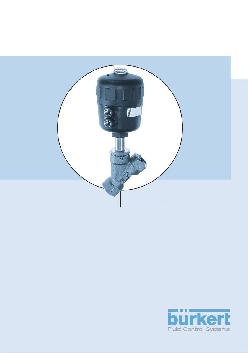
Type 2000/2002
2/2-Way Angle-Seat Valve
3/2-Way Globe Valve
Page 2

We reserve the right to make technical changes without notice.
© 2003 Bürkert Werke GmbH & Co. KG
Operating Instructions No. 893086 - ind 01 - oct 03
Page 3

2/2 OR 3/2-WAY ANGLE-SEAT VALVE TYPE 2000/2002
3/2-WAY GLOBE VALVE TYPE 2002
CONTENTS
GENERAL INFORMATION ................................................................................................................................ 2
Symbols ................................................................................................................................................................. 2
Safety instructions ........................................................................................................................................... 2
Scope of delivery .............................................................................................................................................. 3
Guarantee provisions ..................................................................................................................................... 3
GENERAL DESCRIPTION ................................................................................................................................. 3
TECHNICAL DATA ................................................................................................................................................. 4
Design..................................................................................................................................................................... 4
Actuator size ....................................................................................................................................................... 5
Material ................................................................................................................................................................... 5
Fluids ....................................................................................................................................................................... 5
Temperature range .......................................................................................................................................... 6
Maximum pilot pressure 2/2-way and 3/2-way valve ................................................................... 7
Operating pressure 3/2-way valve ......................................................................................................... 7
Minimum pilot pressures ............................................................................................................................... 8
Port connections ............................................................................................................................................. 10
Pressure surge test to DIN 1988, Part 2 ........................................................................................... 10
english
COMMISSIONING .................................................................................................................................................11
Installation of valve ........................................................................................................................................ 11
Connections for 3/2-way valve ...............................................................................................................11
Electrical connection of pilot valve ........................................................................................................12
MAINTENANCE AND SERVICING.............................................................................................................. 13
Repair.................................................................................................................................................................... 13
Spare parts ........................................................................................................................................................ 13
Spare parts drawings ...................................................................................................................................15
2000/2002 - 1
Page 4
GENERAL INFORMATION
Symbols
The following symbols are used in these instructions:
➔ Marks a work step that you need to perform
CAUTION!
Indicates instructions which, if ignored, puts your health or the
ability of the device or devices to function at risk.
english
NOTE
Indicates important additional information, tips and
recommendations.
Safety instructions
Please observe the instructions contained in this operating manual as well as
the application conditions and permissible parameters as specified in the data
sheet for device Type 2000/2002 so that the device functions flawlessly over a
long service life.
• Observe generally recognised technical regulations during application
planning and operation of the device!
• Installation and maintenance tasks are only to be carried out by trained
personnel equipped with the appropriate tools!
• Observe accident prevention and safety guidelines applicable for electrical
equipment during the operation and maintenance of the device!
• Always disconnect from power before working on the system!
• Please note that systems must first be depressurized before lines and
valves are disconnected!
• Take necessary precautions to prevent unintentional activation or
unauthorized interventions!
• If electrical power supply or pneumatic pressure sources have been
interrupted, make sure that system processes are restarted according to
defined specifications. Monitor the restart of system processes!
• We refuse all liability resulting from a failure to adhere to these instructions as
well as unauthorized operations on the device. Such actions likewise
invalidate the warranty on the devices and accessories.
2 - 2000/2002
Page 5
Scope of delivery
After delivery of goods, please immediately check the contents for damage and
compare the goods actually delivered with those items specified in the delivery
note. Please contact our Customer Service department regarding any
discovered inconsistencies:
Bürkert Steuer- und Regelungstechnik
Service-Abteilung
Chr.-Bürkert-Str. 13-17
D-76453 Ingelfingen, Germany
Tel.: +49 (0)7940 10-111
Fax: +49 (0)7940 10-448
E-mail: service@buerkert.com
or your local Bürkert sales representative, listed at the end of this document.
Guarantee provisions
This document contains no warranty statements. Please refer to our general
terms of sales and business. The prerequisite for the guarantee is the use of the
device in accordance with the prescribed operating conditions.
english
CAUTION!
The guarantee only warrants that the valve, Type 2000/2002, is
free of defects. No liability is accepted for loss or damage of
any type resulting from failure or malfunction of the device.
GENERAL DESCRIPTION
The externally piloted angle-seat valve (Type 2000/2002) / globe valve (Type
2002) consists of a pneumatically operated piston actuator and a 2/2-way
valve body (angle-seat valve Type 2000/2002) / 3/2-way valve body (globe
valve Type 2002). The actuator casing is manufactured of polyamide (PA) or,
alternatively, polyphenylene sulfide (PPS) for special applications. The timeproven, self-adjusting packing gland ensures high seal integrity. The flow
optimizing valve body made of gunmetal (bronze) or stainless steel enables high
flow-rates.
2000/2002 - 3
Page 6
TECHNICAL DATA
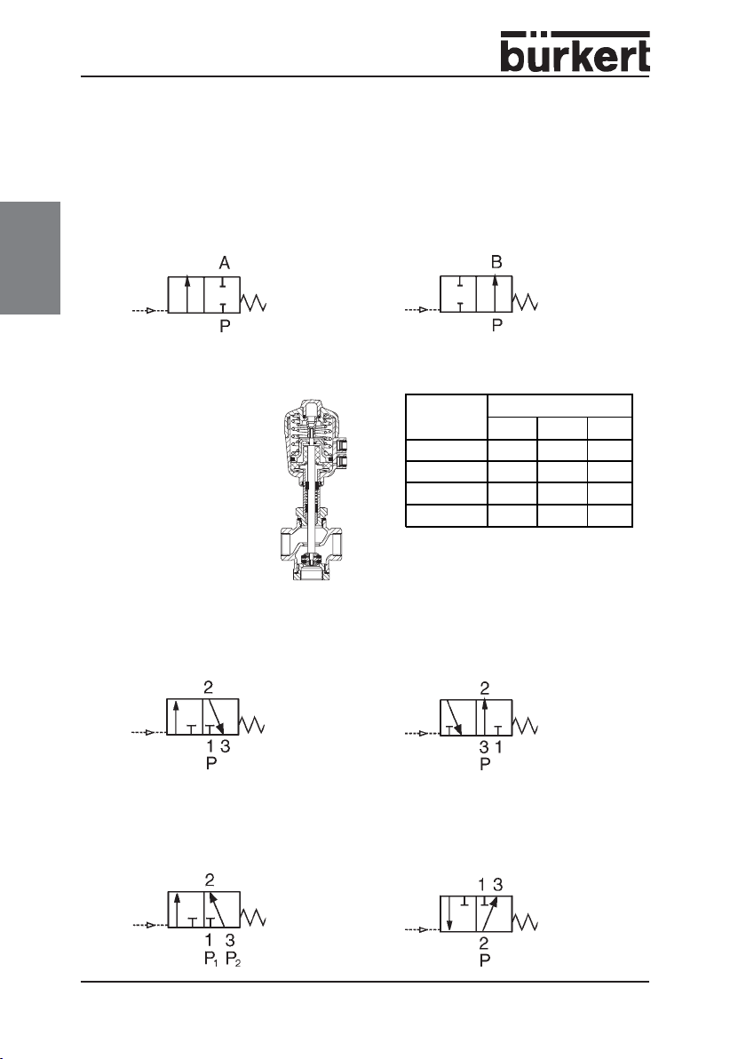
Design
2/2-way globe valve Type 2000/2002)
english
Control function A
Normally closed with spring force
(when de-energised).
3/2-way globe valve Type 2002
Control function A
Port connection 1
normally closed with
spring force (when
de-energised).
3
1
Control function C
Pressure inlet 1 normally closed
(when de-energised); service port 2
is without load.
Control function B
Normally open with spring force
(when de-energised).
Control
function
CPAR
DRAP
EPAP1
FAPB
2
A, B: Service ports
P, P1: Pressure inlets
R: Pressure relief
Ports
123
Control function D
Pressure inlet 3 connected to
service port 2 when de-energised;
relief port 1 closed.
Control function E (mixer valve)
Pressure inlet 3 connected to service
port 2 when de-energised; Pressure
inlet 1 closed.
4 - 2000/2002
Control function F (distributor
valve)
Pressure inlet 2 connected to service
port 3 when de-energised; service
port 1 closed.
Page 7
NOTE
Accidental switching of the pressure inlet lines for the service
port lines during connection of globe valve Type 2002 can
actuate valve operations other than those intended for the
selected control function.
Actuator size
Actuat or s i z e C D E F G H
Ø [mm] 40 50 63 80 100 125
Materials
Valve Type 2000
Threaded body:
Gunmetal,
Body material
Actuator
casing
Seal material PTFE (NBR; FPM, EPDM on request) PTFE
Packing gland
(with silicone
grease)
Stainless steel
1.4408
Body w/weld ends:
St. steel 1.4581
Polyamide or PPS
PTFE V-ring with spring compensation
Angle-seat valve Globe valve
Gunmetal,
St. steel 316L
(316L also
includes 1.4404
and 1.4408)
Type 2002
Gunmetal
PA
(PPS on request)
Fluids
CAUTION!
Observe permissible pressure range as specified on the rating
plate.
english
Water, alcohols, oils, fuels, hydraulic fluid, salt solutions, lyes, organic solvents,
steam.
Pilot fluids: Neutral gases, air
CAUTION!
Valves directing the flow over the seat should not be used for
liquid media; there is a danger of waterhammer!
2000/2002 - 5
Page 8
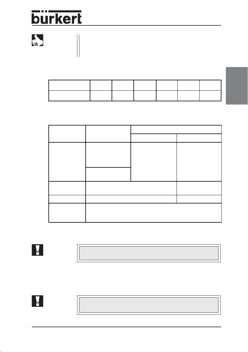
Operating temperature range
english
Actuator
type
B/C Ø 40 to 63 PA
B/C Ø 80 to 125 PA -10 to +180 °C -10 to +60 °C
* short-term up to max. 140 °C
CAUTION!
Ambient
temperature °C
Actuator size
[mm]
D Ø 40 to 80 PPS -10 to +180 °C +5 to +140 °C
D Ø 100 to 125 PPS -10 to +180 °C +5 to +90 °C *
The maximum ambient temperature for a pilot valve is
+55 °C (131 °F)
Actuator
casing
Media temperature
(with PTFE seal)
-10 to
(see Diagram 1)
Ambient
temperature
(see Diagram 1)
-10 to
Diagram 1: Temperature range of the maximum media and ambient
NOTE
6 - 2000/2002
temperature for PA actuators
Temperature °F = (9/5) · (Temperature °C) + 32
Media
temperature °C
Page 9

Maximum pilot pressure 2/2-way and 3/2-way valve
Actuator type Actuator size [mm]
B/C (PA actuator)
D (PPS actuator)
Ø 40 to 100 10 bar
Ø 125 7 bar
Ø 40 to 80 10 bar
Ø 100 to 125 7 bar
Max. permissible
pilot pressure
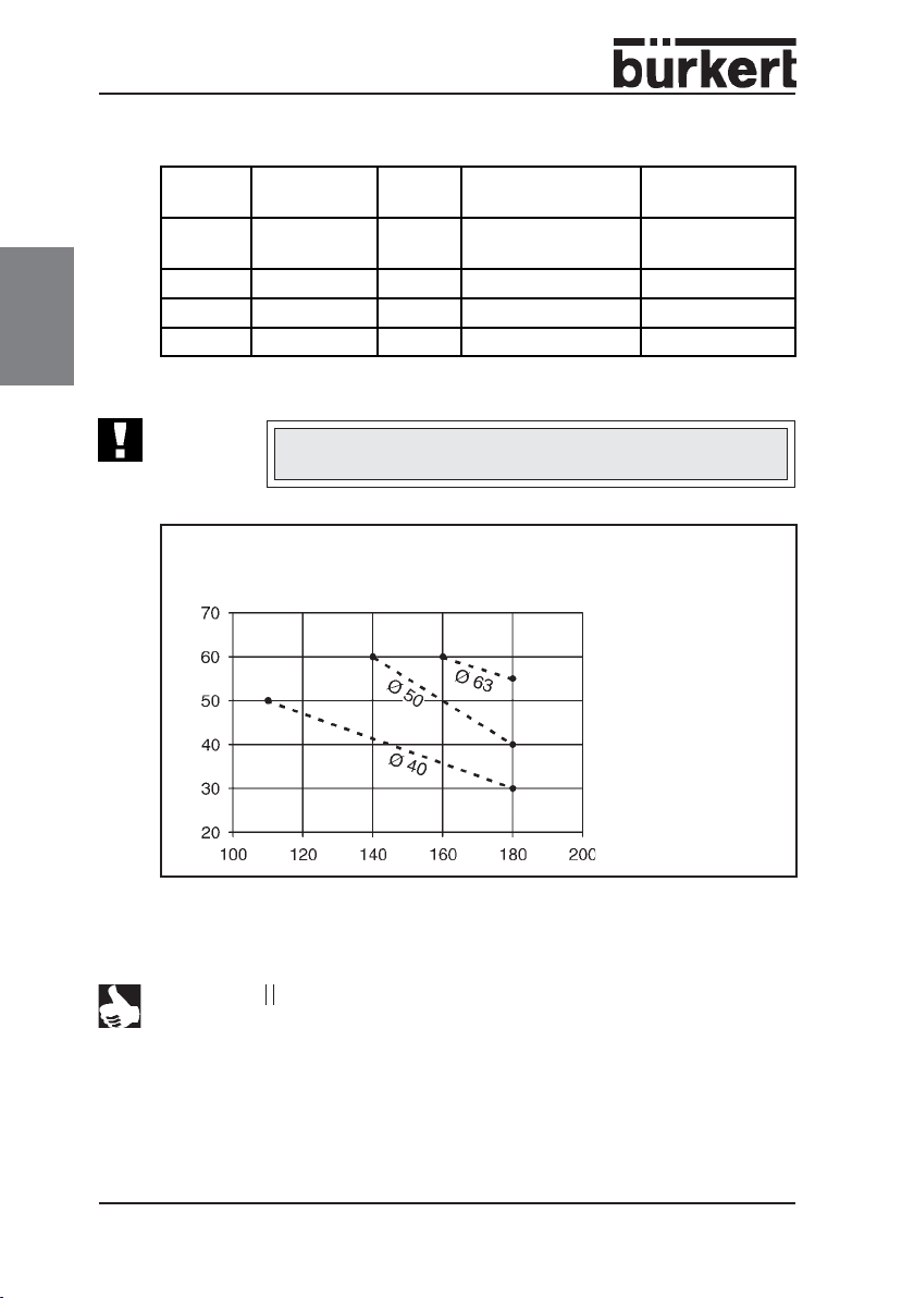
Operating pressure 3/2-way valve
The permissible operating pressure for control function A is:
Actuator
size
Ø [mm]
50 11 4.4
63 16 4.7
63 10 4.9
80 9 6.0
125 14 3.4
125 10 4.3
The maximum permissible operating pressure for control function F equals 16
bar.
Max. permissible operating pressure ∆p
[bar] at DN (flow direction 1 → 2)
13/20 25 32/40 50
Min. pilot
pressure [bar]
english
NOTE
1 bar = 14.5 psi
2000/2002 - 7
Page 10
english
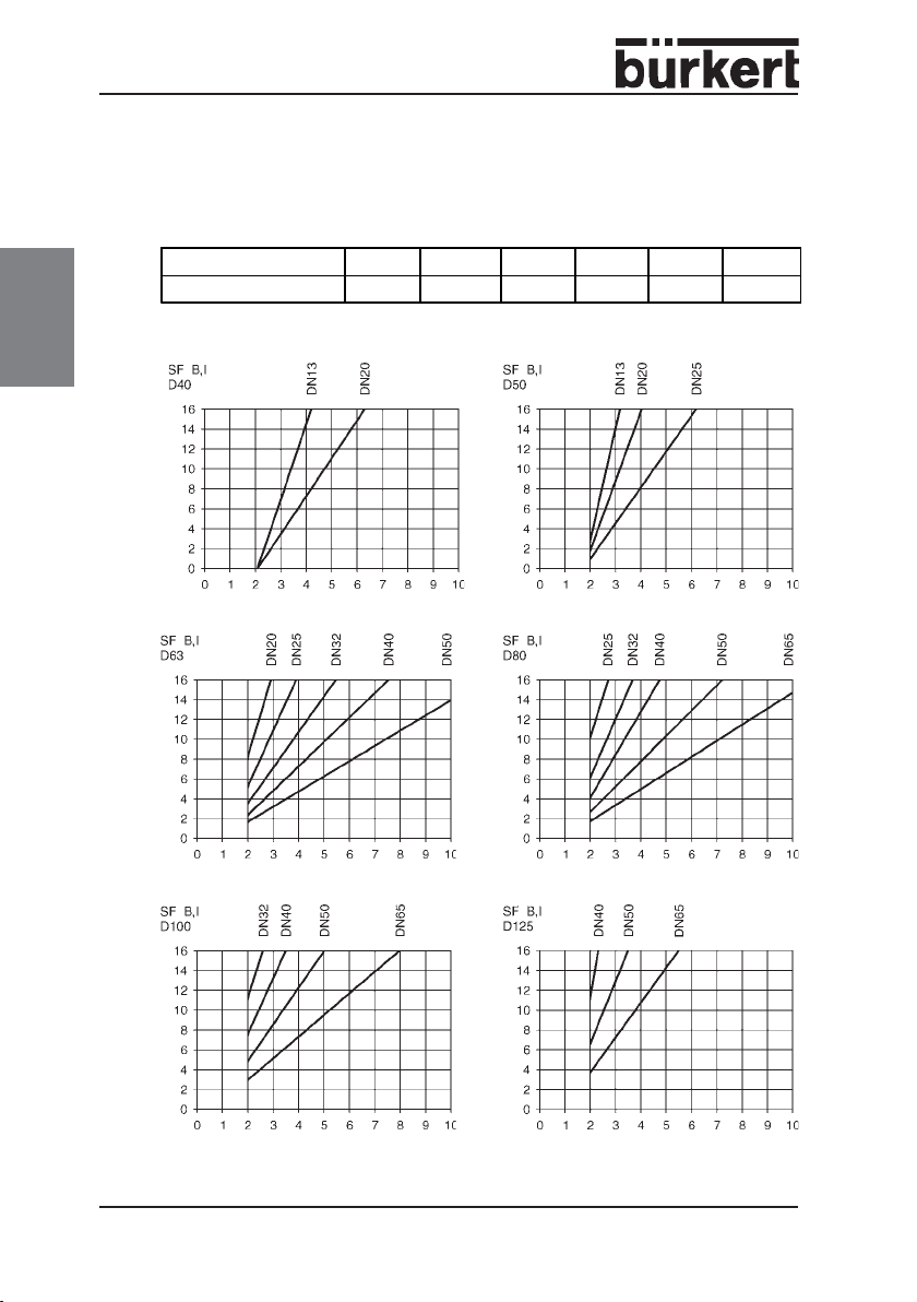
Minimum pilot pressures
Flow direction below seat
closing direction)
The necessary minimum pilot pressure P
Actuator size [mm] Ø 40 Ø 50 Ø 63 Ø 80 Ø 100 Ø 125
P
min
The pilot pressure P
min
(media flows in the opposite direction to valve
for control function A equals:
min
4.0 bar 3.9 bar 4.2 bar 5.0 bar 4.4 bar 3.2 bar
for control function B and I can be found in Diagram 2.
Fluid pressure [bar]
Pilot pressure [bar] Pilot pressure [bar]
Fluid pressure [bar]
Pilot pressure [bar]
Fluid pressure [bar]
Pilot pressure [bar]
Diagram 2: Pilot pressure P
for control function B and I (SFB, I).
min
Fluid pressure [bar]
Fluid pressure [bar]
Pilot pressure [bar]
Fluid pressure [bar]
Pilot pressure [bar]
8 - 2000/2002
Page 11

Flow direction above seat
closing direction)
(media flows in the opposite direction to valve
The pilot pressure P
Fluid pressure [bar]
Pilot pressure [bar]
Fluid pressure [bar]
Pilot pressure [bar] Pilot pressure [bar]
for control function A: see Diagram 3.
min
Fluid pressure [bar]
Fluid pressure [bar]
english
Pilot pressure [bar]
Fluid pressure [bar]
Pilot pressure [bar] Pilot pressure [bar]
Diagram 3: Pilot pressure P
for control function A.
min
Fluid pressure [bar]
2000/2002 - 9
Page 12

english
Port connections
Type 2000 Typ 2002
Angle-seat valve Globe valve
Threaded port:
NPT 3/8 to NPT 2 1/2
(G upon request)
Weld end connection:
-to ISO 4200
-to DIN 11850 R2
-OD tube (U. S.) 1/2" - 2" not available
NPT 3/8 to NPT 2 1/2
(G upon request))
G 1/2 to G 2
(NPT is not available)
Requirements placed on the closing behaviour of angle-seat
valves by DIN 1988 Part 2
To satisfy the requirements of the push-through test to DIN 1988 Part 2, the
exhaust air must be throttled with a throttle having a maximum diameter of 1
mm.
The flow restriction options are as follows:
• Integrated construction of a restrictor or a one-way flow restrictor directly
in the pneumatic actuator.
• Restrictor in the exhaust air port of a 4-way pilot valve.
• Restrictor or one-way flow restrictor directly at the outlet of a
3-way pilot valve.
Bürkert offers the appropriate valves for this purpose.
10 - 2000/2002
Page 13

COMMISSIONING
Installation of valve
Mounting position: any; preferentially with the actuator oriented upward.
➔ Install in accordance with the flow direction.
CAUTION!
In all cases, remove all contamination from the piping (excess
sealing material, metal debris, etc.).
Procedure for installing the valve:
➔ Connect the valve. Make sure the pipe run is correctly oriented.
➔ VA/VS body w/ weld ends: Disassemble and remove actuator before welding.
➔ Threaded body: Only disassemble the actuator if required by customer.
Instructions for actuator disassembly and assembly
Disassembly:
➔ Depressurize the valve seat before the removing and reassembly.
➔ Control function A: Turn on the actuator or release the tension of the return
spring by removing the actuator cover.
➔ Control function B or I: Switch off the pilot pressure.
➔ Screw the threaded nipple out from the body.
Assembly:
➔ Only for the stainless steel body: Grease the nipple threads with a suitable
lubricant.
➔ Screw the threaded nipple and the actuator into the body.
english
2000/2002 - 11
Page 14

Connections for 3/2-way valve
english
Control
function
CPAR
DRAP
EPAP1
FAPB
A, B: Service ports
P, P1: Pressure inlets
R: Pressure relief
Connection of the pilot fluid:
Control function A, to lower connection port
Control function B, to upper connection port
Control function I,at the upper and lower actuator ports using a threaded
G 1/8" (Ø 40) or G 1/4" (Ø 50-125) connection.
The pilot port can rotate 360 degrees.
➔ Use banjo bolts (Type 6012 P, 6014 P) to attach the pilot valves to each respec-
tive pilot air connection on the actuator
➔ Switch on the pilot air at connection port P of the pilot valve
Ports
123
Electrical connection of pilot valve
CAUTION!
Please observe the voltage and current data specified on the
rating plate (voltage tolerance ±10%) as well as information
contained in the data sheet and the pilot valve instructions.
12 - 2000/2002
Page 15

MAINTENANCE AND SERVICING
Repair
CAUTION!
Before dismounting or opening the device, depressurize the
media supply and pilot air supply piping system.
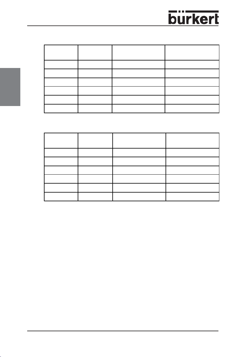
Spare part sets (kits)
Includes as consumable parts a valve seat or sealing seat set (see drawing).
SET 6 Valve seat (2/2-way valve, gunmetal body)
DN
13
20
25*
25**
32
40
50
65
SET 6 Valve seat (2/2-way valve, stainless steel body)
DN
13
20
25*
25**
32
40
50
65
* Actuator size 50, Letter code D.
** Actuator size 63, Letter code E.
Item No.
PTFE seal
010 984 011 065
010 986 011 070
010 988 011 085
159 635 011 044 011 088
011 046 011 107
011 390 011 109
011 064 011 120
Item No.
PTFE seal
011 134 011 234
011 171 011 253
011 202 011 259
160 737 -
011 208 0 11 262
011 209 011 267
011 214 011 26 9
011 216 011 307
Item No.
FPM seal
Item No.
FPM seal
english
2000/2002 - 13
Page 16
SET 5 Sealing set for PA actuator
english
Actuator
size
C (Ø 40) DN 13/20/25
D (Ø 50) DN 13/20/25
E (Ø 63) DN 25-50
F (Ø 80) DN 25-65
G (Ø 100) DN 32-65
H (Ø 125) DN 40-65 011 368 011 387
Fitting
valve sizes
Item No.
Gunmetal body
011 420 011 420
011 308 011 369
011 334 011 372
011 366 001 902
007 763 011 386
St.Steel body
SET 5 Sealing set for PPS actuator
Actuator
size
C (Ø 40) DN 13/20/25
D (Ø 50) DN 13/20/25
E (Ø 63) DN 25-50
F (Ø 80) DN 25-65
G (Ø 100) DN 32-65
H (Ø 125) DN 40-65
Fitting
valve sizes
Item No.
Gunmetal body
011 465 011 465
011 373 011 388
007 765 007 766
011 375 007 767
011 374 011 389
007 764 007 768
St.Steel bod y
Item No.
Item No.
14 - 2000/2002
Page 17

Spare parts drawings
Drawing showing spare part sets for angle-seat valves
Sealing set
SET 5
FPM
english
FPM only used with
gunmetal body
Valve seat
set
SET 6
2000/2002 - 15
Page 18

english
Drawing showing spare part sets for 3/2-way globe valve
Sealing sets
SET 5
(same as 2/2-way
angle-seat valve)
Valve seat
set
(upon
request)
16 - 2000/2002
Page 19

Page 20

Addresses of BC offices/Adressliste BC Länder Europe/Europa
BC-A Austria, Österreich
Burkert-Contromatic Ges.m.b.H.
Diefenbachgasse 1-3
A-1150 Wien
Phone: Int.(+43 1)894 13 33, Nat.(01)894 13 33
Fax: Int.(+43 1)894 13 00, Nat.(01)894 13 00
E-mail: info@buerkert.at
BC-B Belgium, Belgien
Burkert-Contromatic SA
Bijkhoevelaan 3
B-2110 Wijnegem
Phone: Int.(+32 3)325 89 00, Nat.(03)325 89 00
Fax: Int.(+32 3)325 61 61, Nat.(03)325 61 61
E-mail: sales.be@burkert.com
BC-CH Switzerland, Schweiz
Burkert-Contromatic AG Schweiz
Bösch 71
CH-6331 Hünenberg ZG
Phone: Int.(+41 41)785 66 66, Nat.(041)785 66 66
Fax: Int.(+41 41)785 66 33, Nat.(041)785 66 33
E-mail: info.ch@buerkert.ch
BC-CZ Czech Rep., Tschech. Rep.
Burkert-Contromatic Ges.m.b.H.
Branch-Office Austria
Krenova 35
CZ-602 00 Brno
Phone: Int.(+420 543)25 25 05,Nat.(543)25 25 05
Fax: Int.(+420 543)25 25 06,Nat.(543)25 25 06
E-mail: obchod@buerkert.cz
BC-DK Denmark, Dänemark
Burkert-Contromatic A/S
Hørkær 24
DK-2730 Herlev
Phone: Int.(+45 44)50 75 00, Nat.44-50 75 00
Fax: Int.(+45 44)50 75 75, Nat.44-50 75 75
E-mail: info.dk@burkert.com
BC-E Spain, Spanien
Burkert Contromatic, S.A.
Avda. Barcelona, 40
E-08970 Sant Joan Despi, Barcelona
Phone: Int.(+34 93)477 79 80, Nat.(93)477 79 80
Fax: Int.(+34 93)477 79 81, Nat.(93)477 79 81
E-mail: bc-e@burkert.com
BC-F France, Frankreich
Burkert Contromatic France
Rue du Giessen
F-67220 Triembach au Val
Phone: Int.(+33 388)58 91 11,Nat.(0388)58 91 11
Fax: Int.(+33 388)57 20 08,Nat.(0388)57 20 08
E-mail: burkert.france@buerkert.com
BC-GB Great Britain, Großbritannien
Burkert Fluid Control Systems
Brimscombe Port Business Park
Brimscombe, Stroud
Glos, GL5 2QF /Great Britain
Phone: Int.(+44 1453)73 13 53,Nat.(01453)73 13 53
Fax: Int.(+44 1453)73 13 43,Nat.(01453)73 13 43
E-mail: sales.uk@burkert.com
BC-I Italy, Italien
Burkert Contromatic Italiana S.p.A.
Centro Direzionale „Colombirolo“
Via Roma, 74
I-20060 Cassina De’ Pecchi (Mi)
Phone: Int.(+39 02)959 071,Nat.(02)959 071
Fax: Int.(+39 02)959 07251,Nat.(02)959 07 251
E-mail: info@buerkert.it
BC-N Norway, Norwegen
Burkert-Contromatic A/S
Hvamstubben 17
N-2013 Skjetten
Phone: Int.(+47 63)84 44 10,Nat.(63)84 44 10
Fax: Int.(+47 63)84 44 55,Nat.(63)84 44 55
E-mail: buerkert@online.no
BC-NL Netherlands, Niederlande
Burkert-Contromatic BV
Computerweg 9
NL-3542 DP Utrecht
Phone: Int.(+31 346)58 10 10,Nat.(0346)58 10 10
Fax: Int.(+31 346)56 37 17,Nat.(0346)56 37 17
E-mail: sales.nl@burkert.com
BC-P Portugal, Portugal
Burkert Contromatic
Phone: Int.(+35121)21 28 490, Nat.(21)21 28 490
Fax: Int.(+35121)21 28 491, Nat.(21)21 28 491
E-mail: portugal@burkert.com
BC-PL Poland, Polen
Burkert-Contromatic Ges.m.b.H
Branch-Office Austria
Bernardynska street 14 a
PL-02-904 Warszawa
Phone: Int.(+48 22)840 60 10,Nat.(022)840 60 10
Fax: Int.(+48 22)840 60 11,Nat.(022)840 60 11
E-mail: buerkert@buerkert.pl
BC-S Sweden, Schweden
Burkert-Contromatic AB
Skeppsbron 13 B
S-211 20 Malmö
Phone: Int.(+46 40)664 51 00,Nat.(040)664 51 00
Fax: Int.(+46 40)664 51 01,Nat. (040)664 51 01
E-mail: info.se@burkert.com
BC-SA South Africa, Südafrika
Burkert Contromatic Pty. Ltd.
233 Albert Amon Road
Millenium Business Park
Meadowale / Edenvale
Republic of South Africa
Phone: Int.(+27 11)397 29 00, Nat.(011)397 29 00
Fax: Int.(+27 11)397 44 28, Nat.(011)397 44 28
E-mail: sales.za@burkert.com
BC-SF Finland, Finnland
Burkert Oy
Atomitie 5
SF-00370 Helsinki
Phone: Int.(+358 9)549 706 00,Nat.(09)549 70600
Fax: Int.(+358 9)503 12 75,Nat.(09)503 1275
E-mail: sales.fi@burkert.com
BC-TR Turkey, Türkei
Burkert Contromatic Akiskan
Kontrol Sistemleri Ticaret A.S.
1203/8 Sok. No2-E
TR-Yenisehir, Izmir
Phone: Int.(+90 232)459 5395,Nat.(0232)459 5395
Fax: Int.(+90 232)459 7694,Nat.(0232)459 7694
E-mail: burkert@superonline.com
Page 21

Addresses of BC offices/Adressliste BC Länder APAC
BC-HKG (China) Hong Kong, Hongkong
Burkert-Contromatic (China/HK) Ltd.
Unit 708 Prosperity Centre,
77 - 81, Container Port Road
Kwai Chung, N.T.
Phone: Int.(+852)248 012 02,Nat. 248 012 02
Fax: Int.(+852)241 819 45,Nat. 241 819 45
E-mail: info.hkg@burkert.com
BC-CN China, China
Burkert-Contromatic (Suzhou) Co.Ltd.
9-2, Zhu Yuan Road
Suzhou, New District
Jiangsu, 215011
Peoples Republic of China
Phone: Int.(+86 512)6808 19 16,Nat (512)6808 19 16
Fax: Int.(+86 512)6824 51 06,Nat (512)6824 51 06
E-mail: info.chn@burkert.com
BC-KOR Korea, Korea
Burkert Contromatic Korea Co., Ltd.
287-2, Doksan 4 Dong
Kumcheon-ku
Seoul 153-811
Korea
Phone: Int.(+82 2)33462 55 92, Nat.(02)33462 55 92
Fax: Int.(+82 2)33462 55 94, Nat.(02)33462 55 94
E-mail: info.kor@burkert.com
BC-RC Taiwan, Taiwan
Burkert Contromatic Taiwan Ltd.
3 F, No. 475, Kuang-Fu South Road
Taipei 110
Taiwan, R.O.C.
Phone: Int.(+886 2)275 831 99,Nat.(02)275 831 99
Fax: Int.(+886 2)275 824 99,Nat.(02)275 824 99
E-mail: info.rc@burkert.com
BC-RP Philippines, Philippinen
Burkert Contromatic Philippines, Inc.
8467, West Service Road
South Superhighway, Sunvalley
Paranaque City, Metro Manila
Philippines
Phone: Int.(+63 2)776 43 84, Nat.(02)776 43 84
Fax: Int.(+63 2)776 43 82, Nat.(02)776 43 82
E-mail: info.rp@burkert.com
BC-SIN Singapore, Singapur
Burkert Contromatic Singapore Pte. Ltd.
51 Ubi Avenue 1, #03-14
Paya Ubi Industrial Park
Singapore 408933
Singapore
Phone: Int.(+65)6844 2233,Nat.6844 2233
Fax: Int.(+65)6844 3532,Nat.6844 3532
E-mail: info.sin@burkert.com
BC-AUS Australia, Australien
Burkert Fluid Control Systems
No. 2 Welder Road
Seven Hills, NSW 2147
Australia
Phone: Int.(+61 2)1300 888 868,Nat.(02)1300 888 868
Fax: Int.(+61 2)1300 888 076,Nat.(02)1300 888 076
E-mail: sales.au@burkert.com
BC-NZ New Zealand, Neuseeland
Burkert Contromatic Ltd.
2A, Unit L, Edinburgh Street
Penrose, Auckland
New Zealand
Phone: Int.(+64 9)622 28 40,Nat.(09)622 28 40
Fax: Int.(+64 9)622 28 47,Nat.(09)622 28 47
E-mail: sales.nz@burkert.com
BC-J Japan, Japan
Burkert-Contromatic Ltd.
1-8-5 Asagaya Minami
Suginami-ku
Tokyo 166-0004
Japan
Phone: Int.(+81 3)5305 3610,Nat.(03)5305 3610
Fax: Int.(+81 3)5305 3611,Nat.(03)5305 3611
E-mail: info.jpn@burkert.com
Page 22

Addresses of BC offices/Adressliste BC Länder NAFTA
BC-BRA Brazil, Brasilien
Burkert-Contromatic Brasil Ltda.
Rua Américo Brasiliense, 2171 cj.1007
04715-005 São Paulo - SP
Brazil
Phone: Int.(+55 11)5182 0011, Nat.(011)5182 0011
Fax: Int.(+55 11)5182 8899, Nat.(011)5182 8899
E-mail: burkert@burkert.com.br
BC-CDN Canada, Kanada
Burkert Contromatic Inc.
760 Pacific Road, Unit 3
Oakville, Ontario L6L 6M5
Canada
Phone: Int.(+1 905)847 55 66,Nat.(905)847 55 66
Fax: Int.(+1 905)847 90 06,Nat.(905)847 90 06
E-mail: sales.ca@burkert.com
BC-USA (Main Office) USA, USA
Burkert Contromatic USA
2602 McGaw Avenue
Irvine, CA 92614
USA
Phone: Int.(+1 949)223 31 00,Nat.(949)223 31 00
Fax: Int.(+1949)223 31 98,Nat.(949)223 31 98
E-mail: marketing-usa@burkert.com
Page 23

Adressliste Bürkert Fluid Control Systems Deutschland
Vertriebs-Center
Berlin
Bruno-Taut-Straße 4
12524 Berlin
Telefon:Int. (+4930)6797170, Nat. (030)6797170
Fax: Int. (+4930)67971766, Nat. (030)67971766
Hannover
Rendsburger Straße 12
30659 Hannover
Telefon:Int. (+49511)902760, Nat. (0511)902760
Fax: Int. (+49511)9027666, Nat. (0511)9027666
Dortmund
Holzener Straße 70
58708 Menden
Telefon:Int. (+492373)96810, Nat. (02373)96810
Fax: Int. (+492373)968166, Nat. (02373)968166
Frankfurt
Am Flugplatz 27
63329 Egelsbach
Telefon:Int. (+496103)94140, Nat. (06103)94140
Fax: Int. (+496103)941466, Nat. (06103)941466
Stuttgart
Karl-Benz-Straße 19
70794 Filderstadt-Bernhausen
Telefon:Int. (+49711)451100, Nat. (0711)451100
Fax: Int. (+49711)4511066, Nat. (0711)4511066
München
Paul-Gerhardt-Allee 24
81245 München
Telefon:Int. (+4989)8292280, Nat. (089)8292280
Fax: Int. (+4989)82922850, Nat. (089)82922850
Dienstleistungs-Center
Dortmund
Holzener Straße 70
58708 Menden
Telefon: Int. (+492373)968134, Nat. (02373)968134
Fax: Int. (+492373)968132, Nat. (02373)968132
Dresden
Christian-Bürkert-Straße 2
01900 Großröhrsdorf
Telefon: Int. (+4935952)36-300, Nat. (035952)36-300
Fax: Int. (+4935952)36-551, Nat. (035952)36-551
Service-Center
Ingelfingen
Christian-Bürkert-Straße 13-17
74653 Ingelfingen
Telefon: In t. (+ 497940)10-111, Nat. (07940)10-111
Fax: Int. (+497940)10-448, Nat. (07940)10-448
E-mail: info@de.buerkert.com
Page 24

The smart choice
of Fluid Control Systems
www.burkert-usa.com
 Loading...