

Page 1
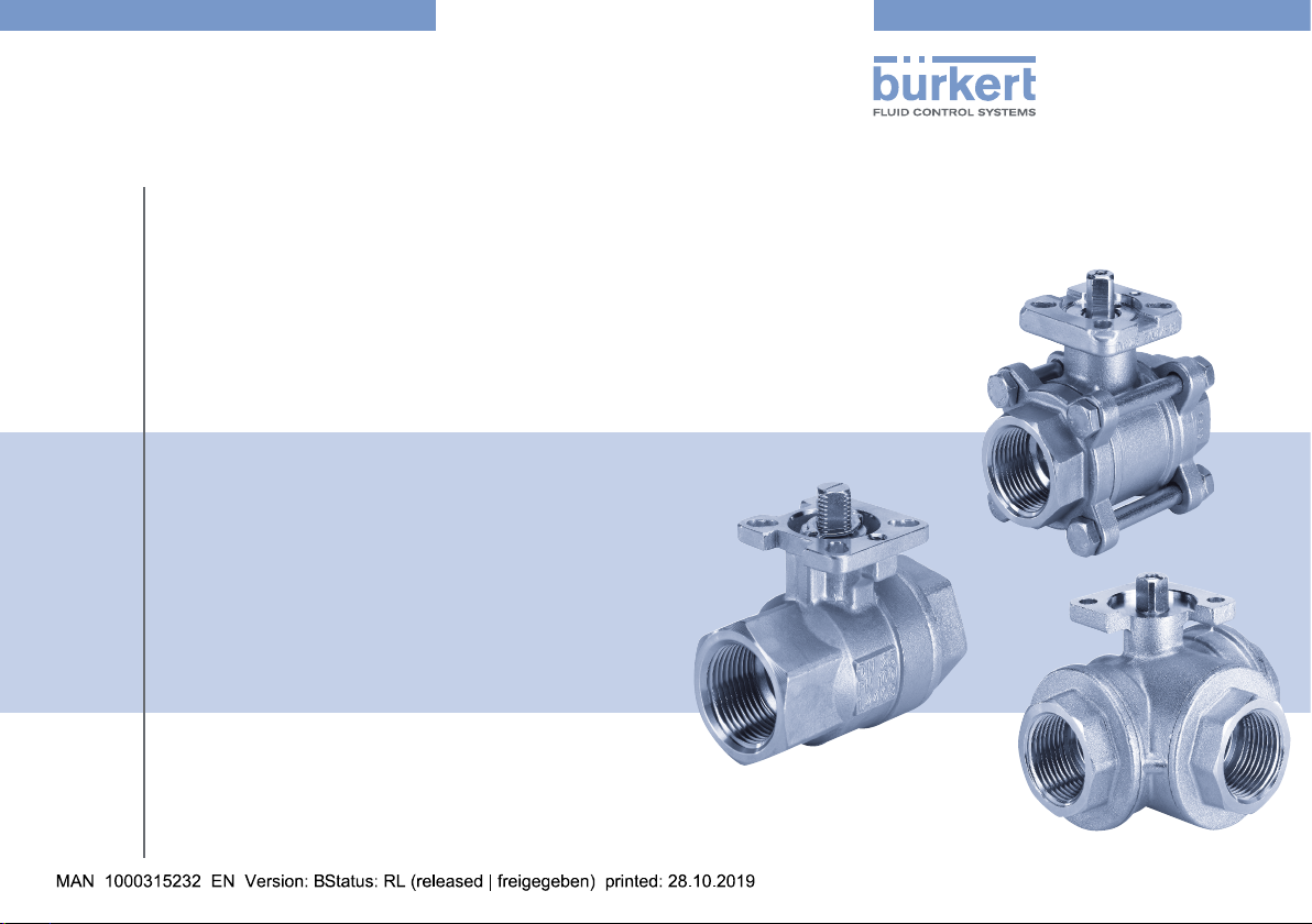
Type 2651, 2654, 2654 Hygienic,
2660, TKU001/2/3
Stainless steel and brass ball valves in 2-way and 3-way design
Kugelhähne aus Edelstahl und Messing in 2- und 3-Wege-Variante
Robinets à boisseau sphérique en acier inoxydable et en laiton, modèles à 2 ou 3 voies
Operating Instructions
Bedienungsanleitung
Manuel d‘utilisation
Page 2

We reserve the right to make technical changes without notice.
Technische Änderungen vorbehalten.
Sous réserve de modification techniques.
© Bürkert Werke GmbH & Co. KG, 2008 - 2019
Operating Instructions 1910/07_EU-ML_00805911 / Original DE
Page 3
Type 2651, 2654, 2654 Hygienic,
2660, TKU001/2/3
Operating instructions
1 OPERATING INSTRUCTIONS ............................................... 3
1.1 Symbols ....................................................................... 3
2 INTENDED USE .................................................................... 4
3 BASIC SAFETY INSTRUCTIONS .......................................... 5
4 GENERAL INFORMATION .................................................... 6
4.1 Contact addresses ...................................................... 6
4.2 Warranty ...................................................................... 6
4.3 Information on the Internet .......................................... 6
5 SYSTEM DESCRIPTION ....................................................... 6
6 TECHNICAL DATA ................................................................. 7
7 INSTALLATION ...................................................................... 9
7.1 Ball valve with screw thread ........................................ 9
7.2 Ball valve with welded connection .............................. 9
8 OPERATION AND FUNCTIONS .......................................... 10
8.1 Operation ................................................................... 10
8.2 Switch positions ........................................................ 11
9 SPARE PARTS ..................................................................... 11
10 MAINTENANCE ................................................................... 12
10.1 Replacing the wearing part sets for ball valves
Type 2654 and TKU001 ............................................. 12
1 OPERATING INSTRUCTIONS
The operating instructions describe the entire life cycle of the device.
Keep these instructions in a location which is easily accessible
to every user and make these instructions available to every new
owner of the device.
The operating instructions contain important safety information.
Failure to observe these instructions may result in hazardous
situations.
▶ The operating instructions must be read and understood.
1.1 Symbols
DANGER!
Warns of an immediate danger.
▶ Failure to observe the warning may result in a fatal or serious
injury.
WARNING!
Warns of a potentially dangerous situation.
▶ Failure to observe the warning may result in serious injuries
or death.
11 TRANSPORT, STORAGE, DISPOSAL ................................. 14
english
3
Page 4
Type 2651, 2654, 2654 Hygienic,
2660, TKU001/2/3
Intended use
CAUTION!
Warns of a possible danger.
▶ Failure to observe this warning may result in a medium or
minor injury.
NOTE!
Warns of damage to property.
▶ Failure to observe the warning may result in damage to the
device or the equipment.
Indicates important additional information, tips and
recommendations.
Refers to information in these operating instructions or in
other documentation.
▶ designates instructions for risk prevention.
→ designates a procedure which you must carry out.
2 INTENDED USE
The ball valves types 2651, 2654, 2654 Hygienic, 2660 and
TKU001/2/3 (in general below as “Ball valves”) are intended for the
installation to pneumatic or electric rotary actuators. They can be
used indoors as well as outdoors, in compliance with the permissible operating conditions.
Non-intended use of the ball valves can be dangerous to
people, nearby equipment and the environment.
▶ The ball valves are used for shutting o media ows in a
wide range of industrial applications.
▶ The ball valves may be used only in conjunction with third-
party devices and components recommended and authorized
by Bürkert.
▶ During use observe the authorised data and operating conditions
specied in the contract documents and operating instructions
as well as the range of applications described in „5 System
Description“.
▶ Correct transportation, correct storage and installation and
careful use and maintenance are essential for reliable and
faultless operation.
▶ Operate the ball valves only with media which do not cor-
rode the valve body or seal material.
▶ Use the ball valves only as intended.
4
english
Page 5
Type 2651, 2654, 2654 Hygienic,
2660, TKU001/2/3
Basic Safety Instructions
3 BASIC SAFETY INSTRUCTIONS
These safety instructions do not make allowance for any:
• Contingencies and events which may arise during the installation,
operation and maintenance of the devices.
• Local safety regulations; the operator is responsible for observing
these regulations, also with reference to the installation personnel.
WARNING!
Unintentional activation or non-permitted impairment may
cause general hazardous situations through to physical injury.
To prevent injury, ensure that:
▶ The system cannot be activated unintentionally.
▶ Installation and repair work may be carried out by authorized
technicians only and with the appropriate tools.
▶ After an interruption in the power supply or uid supply,
ensure that the process is restarted in a dened or controlled
manner.
▶ The device may be operated only when in perfect condition
and in consideration of the operating instructions.
▶ Do not physically stress the valve body (e.g. by placing
objects on it or standing on it).
▶ Do not make any external modications to the valve body.
▶ The general rules of technology apply to application planning
and operation of the device.
DANGER!
Danger – high pressure.
There is a serious risk of injury when reaching into the
equipment.
▶ Turn o the pressure and release the pressure in the pipes
before loosening pipes and valves!
CAUTION!
The general rules of technology apply to application planning
and operation of the device.
Failure to observe these rules may result in injuries and/or
damage to the device and possibly the area around it as well.
▶ Observe the general rules of technology!
NOTE!
▶ Operate the ball valves only when they are in perfect condi-
tion and in accordance with the operating instructions.
english
5
Page 6

Type 2651, 2654, 2654 Hygienic,
2660, TKU001/2/3
General information
4 GENERAL INFORMATION
4.1 Contact addresses
Germany
Bürkert Fluid Control Systems
Sales Center
Christian-Bürkert-Str. 13-17
D-74653 Ingelngen
Tel. : +49 (0) 7940 - 10 91 111
Fax: +49 (0) 7940 - 10 91 448
E-mail: info@burkert.com
International
Contact addresses can be found on the nal pages of the printed
operating instructions.
And also on the Internet at: www.burkert.com
4.2 Warranty
The warranty is only valid if the device is used as intended in accor-
dance with the specied application conditions.
4.3 Information on the Internet
The operating instructions and data sheets for Type 2651, 2654,
2654 Hygienic, 2660 and TKU001/2/3 can be found on the
Internet at: www.burkert.com
5 SYSTEM DESCRIPTION
The ball valves are used for shutting o media ows in a wide range
of industrial applications.
They are particularly suitable for application conditions which make
high demands in the areas of thermal loads and are also suitable
for applications which use aggressive media.
The ball valves are available in dierent sizes. They are equipped
with a mechanical interface as per ISO 5211 which is used to install
a pneumatic or electric rotary actuator.
On request the ball valves can be supplied complete with a
pneumatic actuator (Types 2652, 2655, 8805) or an electric
actuator (Type 8804).
6
english
Page 7

Type 2651, 2654, 2654 Hygienic,
2660, TKU001/2/3
Technical data
6 TECHNICAL DATA
Allowable temperatures
Stainless steel
valve body
Brass valve body –20...+150 °C
The temperature limit values of the actuators are usually
lower. Therefore, the lowest temperature limit values of
included system components (ball valve and actuator)
must be observed.
Allowable Media Aggressive, neutral, gaseous and liquid media
Allowable pressure
range
Material
Type Valve body Ball Sealing
2651 Stainless steel 1.4408
2654 Stainless steel 1.4408
2654
Hygienic
Stainless steel 1.4435
2660 Brass, nickel-plated
TKU
001/2/3
Stainless steel 1.4408
Steel 1.0619
–10...+200 °C
(see pressure/temperature diagram)
(see pressure/temperature diagram)
Depending on the design between 0 and
16/25/40/63/100 bar (see data sheets and
pressure/temperature diagram)
Stainless steel
1.4401
Stainless steel
1.4401
Stainless steel
1.4435
Brass, hard
chrome-plated
Stainless steel
1.4401
PTFE
PTFE
SS-PTFE
(FDA) /
PTFE (FDA)
PTFE
PTFE
Pressure/Temperature diagrams:
50
1/4“, 3/8“, 1/2“, 3/4“, 1“, 1 1/4“
40
30
1 1/2“, 2“, 2 1/2“
Pressure [bar]
20
10
0
25 50 75 100 125 150
Temperature [°C]
Fig. 1: Pressure/Temperature diagram brass valve body
(Type 2660)
english
7
Page 8

Type 2651, 2654, 2654 Hygienic,
2660, TKU001/2/3
Technical data
Ball valve with PTFE-valve seat seal:
Pressure [bar]
110
100
90
80
70
63
50
40
30
16
10
2.5 bar
-10 0 10050 150 200
Temperature [°C]
Fig. 2: Pressure/Temperature diagram stainless steel valve
body (Types 2651, 2654, 2654 Hygienic, TKU 001/2/3)
Ball valve with stainless steel reinforced PTFE seat seal:
Pressure [bar]
110
100
90
80
70
63
50
40
30
20
10
12-13
bar
-10 0 10050 150 200
Temperature [°C]
Fig. 3: Pressure/Temperature diagram stainless steel valve
body (Type 2654 Hygienic)
8
english
Page 9

Type 2651, 2654, 2654 Hygienic,
2660, TKU001/2/3
Installation
7 INSTALLATION
DANGER!
Risk of injury from high pressure in the equipment.
There is a serious risk of injury when reaching into the equipment.
▶ Turn o the pressure and release the pressure in the pipes
before loosening pipes and valves.
WARNING!
Risk of injury due to improper installation.
Improper installation may result in injuries as well as damage to
the device and the area around it.
▶ This work may be carried out by authorised technicians only
and with the appropriate tools.
Risk of injury due to unintentional activation.
Hazardous situations may arise due to unintentional activation
of the system.
▶ Take appropriate measures to prevent the equipment from
being unintentionally activated.
7.1 Ball valve with screw thread
Check that the pipes which are to be connected to the
ball valve are on one level. This will prevent mechanical
tension on the screw joint.
→ Screw the ball valve to the pipe.
→ Check that the ball valve is rmly attached to the pipe to ensure
appropriate tightness.
7.2 Ball valve with welded connection
NOTE!
To prevent damage to the ball valve and the contained seal,
disassemble the ball valve from the pipeline prior to welding.
Disassembling the ball valve:
→ Undo the four body bolts and disassemble the ball valve into
three parts.
→ Remove the seal from the connection element.
→ Weld the connection element to the pipeline.
→ Assemble the ball valve and x it into position using the four
body bolts!
Make sure the seals are seated correctly!
Refer to the following table for tightening torques!
Welding of the ball valve Type 2654 Hygienic is possible
under the following conditions:
• Orbital welding using orbital welding equipment.
• The heat impact on the seals must not exceed the
maximum temperature. The maximum temperature for
the stainless steel valve body is +200 °C.
english
9
Page 10

Type 2651, 2654, 2654 Hygienic,
2660, TKU001/2/3
Operation and functions
NOTE!
If the seals are exposed to a temperature greater than the
maximum temperature during the welding process, all the
seals must be replaced with new ones.
Tightening torques of
the installation bolts
Type
Size
DN08 1/4" 8.7 - - 163.3
DN10 3/8" 8.7 - - 163.3
DN15 1/2" 20.4 19.6 234.7 214.3
DN20 3/4" 20.4 19.6 265.3 265.3
DN25 1" 20.4 39.2 336.7 336.7
DN32 1 1/4" 40.8 39.2 428.6 428.6
DN40 1 1/2" 40.8 65.7 530.6 530.6
DN50 2" 40.8 65.7 714.3 714.4
DN65 2 1/2" 81.6 65.7 785.7 785.7
DN80 3" 81.6 86.2 867.3 867.3
DN100 4" 81.6 86.2 1020.4 -
2654
Type
TKU001
(3-piece)
[Nm]
Type
2651
ange
[Nm]
Tightening torques of
the end caps
Type
TKU001
compact
ange
[Nm]
Type
2651
[Nm]
8 OPERATION AND FUNCTIONS
WARNING!
Danger due to improper operation.
Improper operation may result in injuries as well as damage to
the device and the area around it.
▶ The operating personnel must know and have understood
the contents of the operating instructions.
▶ Observe the safety instructions and intended use.
▶ Only adequately trained personnel may operate the equip-
ment/the device.
8.1 Operation
Via the mechanical interface as per ISO 5211, the ball valves can
be connected to a pneumatic rotary actuator (e.g. Types 2050,
2051 or 2052) or an electric rotary actuator (e.g. Types 3003,
3004 or 3005).
The operating instructions of the actuators you can nd on the
Bürkert homepage: www.burkert.com
10
english
Page 11

Type 2651, 2654, 2654 Hygienic,
2660, TKU001/2/3
Spare parts
8.2 Switch positions
The ball valves are available in 2-way or 3-way design.
The 3-way designs are available with the following switching
positions:
Ball bore T L
Position
0°
90°
Switching
position
T1 T2 T3 L4
9 SPARE PARTS
CAUTION!
Risk of injury and / or damage by the use of incorrect parts.
Incorrect accessories and unsuitable spare parts may cause
injuries and damage the device and the surrounding area.
▶ Use original accessories and original spare parts from Bürkert only.
Wearing part sets for type 2654 and 2654 Hygienic
Contents:
Wearing part sets for Type TKU001 - 3-piece
Contents:
• 4 chevron seals
• O-ring
• thrust collar
• 2 ball seats
• 2 body seals
• 3 chevron seals
• thrust collar
• 2 ball seals
• 2 body seals
english
11
Page 12

Type 2651, 2654, 2654 Hygienic,
2660, TKU001/2/3
Spare parts
Type
2654
Size
DN08 - 773821 - 772840
DN10 773127 773822 773013 772841
DN12 770180 - - -
DN15 789821 773823 773014 772842
DN20 789822 773824 773015 772843
DN25 789823 773825 773016 772844
DN32 789824 773826 773017 772845
DN40 789825 773827 773018 772846
DN50 789826 773828 773019 770494
DN65 789827 773829 773020 772847
DN80 789828 773830 773021 772686
DN100 789829 773831 773022 772848
PTFE
seal
FKM
o-ring
Type 2654
Hygienic
PTFE-FDA seal
(stainless steel
reinforced)
silicone o-ring
Type 2654
Hygienic
PTFEFDA seal
silicone
o-ring
Type
TKU001
3-pieces
PTFE seal
10 MAINTENANCE
The ball valves are maintenance friendly when operated according
to the instructions indicated in this manual.
10.1 Replacing the wearing part sets for ball valves Type 2654 and TKU001
DANGER!
Risk of injury from high pressure in the system.
Acute risk of injury when intervening in the system.
▶ Always switch o the pressure and bleed the lines before
undoing the lines and valves!
WARNING!
Risk of injury through improper maintenance.
Improper maintenance may result in injuries as well as damage
to the device and its surroundings.
▶ Maintenance may only be carried out by authorised techni-
cians using the appropriate tools!
Risks due to unintentional activation of the system!
Unintentional start-up of the system during maintenance and
repair work may lead to injuries and damage.
▶ Secure the system against unintentional activation.
12
english
Page 13

Type 2651, 2654, 2654 Hygienic,
2660, TKU001/2/3
Spare parts
10.1.1 Replacing the ball seal and/or body
seal
→ Move the ball valve to the open position.
→ Undo the body bolts.
→ Swivel out the centre part.
→ Move the ball valve to the closed position.
→ Remove the ball.
→ Replace the ball seal and body seal.
→ Insert the ball.
→ Move the ball valve to the open position.
→ Tighten the body bolts to the respective tightening torque
(see section „7.2“).
→ Check the ball valve for leak-tightness.
10.1.2 Replacing the ball stem seal and/or
the o-ring
→ Move the ball valve to the open position.
→ Undo the body part.
→ Swivel out the centre part.
→ Move the ball valve to the closed position.
→ Remove the ball.
→ Undo and remove the nut from the ISO ange.
→ Remove the disc spring.
→ Slide the ball stem inwards and remove it.
→ Remove and replace the ball stem seal and package.
→ Cut the o-ring o the stem seal and replace it.
→ Replace the thrust collar.
→ Insert the stem seal from the inside.
→ Insert the disc spring in the correct position.
Fig. 4: Installation position of the disc spring
→ Insert the ball.
→ Move the ball valve to the open position.
→ Tighten the body bolts to the respective tightening torque
(see section „7.2“).
→ Check the ball valve for leak-tightness.
english
13
Page 14

11 TRANSPORT, STORAGE,
DISPOSAL
NOTE!
Transport damages.
Inadequately protected equipment may be damaged during
transport.
▶ During transportation protect the device against wet and dirt
in shock-resistant packaging.
▶ Avoid exceeding or dropping below the allowable storage
temperature.
▶ Protect the pneumatic connections from damage by placing
caps on them.
Incorrect storage may damage the device.
▶ Store the device in a dry and dust-free location!
▶ Storage temperature –40...+55 °C.
Damage to the environment caused by device components
contaminated with media.
▶ Dispose of the device and packaging in an environmentally
friendly manner.
▶ Observe applicable regulations on disposal and the
environment.
▶ Observe national waste disposal regulations.
Type 2651, 2654, 2654 Hygienic,
2660, TKU001/2/3
Transport, Storage, Disposal
14
english
Page 15

www.burkert.com
 Loading...