

Page 1

Type 2651, 2654, 2660, TKU 001
Stainless-steel and brass ball valves in 2-way and 3-way design
Kugelhähne aus Edelstahl und Messing in 2-Wege und 3-Wege Ausführung
Robinets à boisseau sphérique en acier inoxydable et en laiton, modèles à 2 ou 3 voies
Operating Instructions
Bedienungsanleitung
Manuel d‘utilisation
Page 2

We reserve the right to make technical changes without notice.
Technische Änderungen vorbehalten.
Sous resérve de modification techniques.
© 2008 - 2010 Bürkert Werke GmbH
Operating Instructions 1011/03_EU-ML_00805911 / Original DE
Page 3
Types 2651, 2654, 2660,
TKU 001
Contents
1. OPERATING INSTRUCTIONS ...................................................................4
1.1. Symbols ..............................................................................................4
2. INTENDED USE ................................................................................................5
2.1. Restrictions ........................................................................................5
2.2. Predictable Misuse ..........................................................................5
3. BASIC SAFETY INSTRUCTIONS .............................................................6
4. GENERAL INFORMATION ...........................................................................7
4.1. Contact address ............................................................................... 7
4.2. Warranty ............................................................................................. 7
4.3. Information on the Internet ............................................................. 7
5. SYSTEM DESCRIPTION ...............................................................................7
5.1. Intended Application Area .............................................................. 7
5.2. Functions ............................................................................................ 7
6. TECHNICAL DATA ...........................................................................................8
6.1. Operating conditions ....................................................................... 8
6.2. General technical data .................................................................... 8
7. INSTALLATION ..................................................................................................9
7.1. Safety instructions ...........................................................................9
7.2. Installation in the Pipeline .............................................................10
8. OPERATION AND FUNCTION ................................................................10
8.1. Safety instructions .........................................................................10
8.2. Operation of the ball valve ...........................................................10
8.3. Functions ..........................................................................................11
9. SPARE PARTS ................................................................................................11
10. MAINTENANCE, TROUBLESHOOTING .......................................... 12
10.1. Maintenance Work .......................................................................12
11. PACKAGING, TRANSPORT, STORAGE, DISPOSAL ................ 12
english
3
Page 4
Types 2651, 2654, 2660,
TKU 001
Operating Instructions
1. OPERATING INSTRUCTIONS
The operating instructions describe the entire life cycle of the device.
Keep these instructions in a location which is easily accessible to
every user and make these instructions available to every new owner
of the device.
The operating instructions contain important safety information!
Failure to observe these instructions may result in hazardous
situations.
• The operating instructions must be read and understood.
1.1. Symbols
DANGER!
Warns of an immediate danger!
• Failure to observe the warning may result in a fatal or serious
injury.
WARNING!
Warns of a potentially dangerous situation!
• Failure to observe the warning may result in serious injuries or
death.
CAUTION!
Warns of a possible danger!
• Failure to observe this warning may result in a medium or minor
injury.
NOTE!
Warns of damage to property!
• Failure to observe the warning may result in damage to the
device or the equipment.
Indicates important additional information, tips and
recommendations.
Refers to information in these operating instructions or in
other documentation.
→ designates a procedure which you must carry out.
4
english
Page 5

Types 2651, 2654, 2660,
TKU 001
Intended Use
2. INTENDED USE
The ball valves types 2651, 2654 and 2660 (in general below as "Ball
valves") are intended for the installation to pneumatic or electric rotary
actuators. They can be used indoors as well as outdoors, in compliance
with the permissible operating conditions.
Non-intended use of the ball valves can be dangerous to
people, nearby equipment and the environment.
• The ball valves are used for shutting off media flows in a wide
range of industrial applications.
• The ball valves may be used only in conjunction with third-party
devices and components recommended and authorized by Bürkert.
• During use observe the authorised data and operating conditions
specified in the contract documents and operating instructions
as well as the range of applications described in „5.1. Intended
Application Area“.
• Correct transportation, correct storage and installation and careful use
and maintenance are essential for reliable and faultless operation.
• Use the ball valves only as intended.
2.1. Restrictions
If exporting the System/Device, observe any existing restrictions.
2.2. Predictable Misuse
• Operate the ball valves only with media which do not corrode the
housing or seal material.
• Do not physically stress the housing (e.g. by placing objects on it
or standing on it).
• Do not make any external modifications to the housing.
english
5
Page 6

Types 2651, 2654, 2660,
TKU 001
Basic Safety Instructions
3. BASIC SAFETY
INSTRUCTIONS
These safety instructions do not make allowance for any:
• Contingencies and events which may arise during the installation,
operation and maintenance of the devices.
• Local safety regulations; the operator is responsible for observing
these regulations, also with reference to the installation personnel.
WARNING!
Unintentional activation or non-permitted impairment may
cause general hazardous situations through to physical injury.
To prevent injury, ensure that:
• The system cannot be activated unintentionally.
• Installation and repair work may be carried out by authorized
technicians only and with the appropriate tools.
• After an interruption in the power supply or fluid supply, ensure
that the process is restarted in a defined or controlled manner.
• The device may be operated only when in perfect condition and
in consideration of the operating instructions.
• The general rules of technology apply to application planning
and operation of the device.
DANGER!
Danger – high pressure!
• There is a serious risk of injury when reaching into the equipment.
• Turn off the pressure and release the pressure in the pipes
before loosening pipes and valves!
CAUTION!
The general rules of technology apply to application planning
and operation of the device!
• Failure to observe these rules may result in injuries and/or damage to the device and possibly the area around it as well.
• Observe the general rules of technology!
NOTE!
The ball valves were developed with due consideration given to
the accepted safety rules and are state-of-the-art. Nevertheless,
dangerous situations may occur.
• Operate the ball valves only when they are in perfect condition
and in accordance with the operating instructions.
Failure to observe this operating manual and its operating instructions as well as unauthorized tampering with the device release us
from any liability and also invalidate the warranty covering the device
and accessories!
6
english
Page 7

Types 2651, 2654, 2660,
TKU 001
General Information
4. GENERAL INFORMATION
4.1. Contact address
Germany
Bürkert Fluid Control Systems
Sales Center
Chr.-Bürkert-Str. 13-17
D-74653 Ingelfingen
Tel.: +49 (0)7940 - 10 91 111
Fax: +49 (0)7940 - 10 91 448
E-mail: info@de.burkert.com
International
Contact addresses can be found on the final pages of the printed
operating instructions.
And also on the Internet at: www.burkert.com
4.2. Warranty
The warranty is only valid if the device is used as intended in accordance
with the specified application conditions.
4.3. Information on the Internet
The operating instructions and data sheets for Type 2651, 2654, 2660
and TKU 001 can be found on the Internet at: www.burkert.com
5. SYSTEM DESCRIPTION
5.1. Intended Application Area
The ball valves are used for shutting off media flows in a wide range
of industrial applications.
They are particularly suitable for application conditions which make
high demands in the areas of thermal loads and are also suitable for
applications which use aggressive media.
5.2. Functions
The ball valves for shutting off media flows are available in different
sizes. They are equipped with a mechanical interface as per ISO 5211.
This interface is used to install a pneumatic or electric rotary actuator
to the ball valves.
On request the ball valves can be supplied complete with a
pneumatic actuator (Types 2652, 2655, 8805) or an electric
actuator (Type 8804).
english
7
Page 8

Types 2651, 2654, 2660,
TKU 001
Technical Data
6. TECHNICAL DATA
6.1. Operating conditions
Allowable temperatures
Ambient temperature: Stainless-steel housing -10 – +80 °C
Brass housing -20 – +80 °C
Medium temperature: Stainless-steel housing -10 – +100 °C
Brass housing -20 – +100 °C
Media: Aggressive, neutral, gaseous and liquid
media and vapours
Pressure ranges: 0 – 100 bar (depending on the design)
6.2. General technical data
6.2.1. Mechanical data
Housing material: Stainless steel 1.4401; Nickel-plated brass
Sealing material: PTFE
6.2.2. Pressure-temperature graphs,
2/2-way and 3/2-way ball valves
50
40
30
20
Pressure [bar]
10
0
-20 1201008060400 20 140160
Fig. 1: Pressure-temperature Graph / Brass housing
40 bar
30 bar
25 bar
16 bar
10 bar
Temperature [°C]
8
english
Page 9

Types 2651, 2654, 2660,
100 bar
63 bar
40 bar
Pressure [bar]
TKU 001
Installation
7. INSTALLATION
7.1. Safety instructions
DANGER!
Risk of injury from high pressure in the equipment!
There is a serious risk of injury when reaching into the equipment.
• Turn off the pressure and release the pressure in the pipes before
loosening pipes and valves!
WARNING!
16 bar
0 bar
Temperature [°C]
100400
200 230
Fig. 2: Pressure-temperature Graph / Stainless-steel housing
Risk of injury due to improper installation!
Improper installation may result in injuries as well as damage to
the device and the area around it.
• This work may be carried out by authorised technicians only and
with the appropriate tools!
Risk of injury due to unintentional activation!
Hazardous situations may arise due to unintentional activation of
the system.
• Take appropriate measures to prevent the equipment from being
unintentionally activated.
english
9
Page 10

Types 2651, 2654, 2660,
TKU 001
Operation and function
7.2. Installation in the Pipeline
Procedure:
→ Check that the pipes which are to be connected to the ball valve are
on one level. This will prevent mechanical tension on the screw joint.
→ Screw the ball valve to the pipe.
→ Check that the ball valve is firmly attached to the pipe to ensure
appropriate tightness.
8. OPERATION AND FUNCTION
8.1. Safety instructions
WARNING!
Danger due to improper operation!
Improper operation may result in injuries as well as damage to the
device and the area around it.
• The operating personnel must know and have understood the
contents of the operating instructions.
• Observe the safety instructions and intended use.
• Only adequately trained personnel may operate the equipment/
the device.
8.2. Operation of the ball valve
Via the mechanical interface as per ISO 5211, the ball valves can be
connected to a pneumatic rotary actuator (e.g. Types 2050 or 2051)
or an electric rotary actuator (e.g. Types 3003, 3004 or 3005).
10
english
Page 11
Types 2651, 2654, 2660,
TKU 001
Spare parts
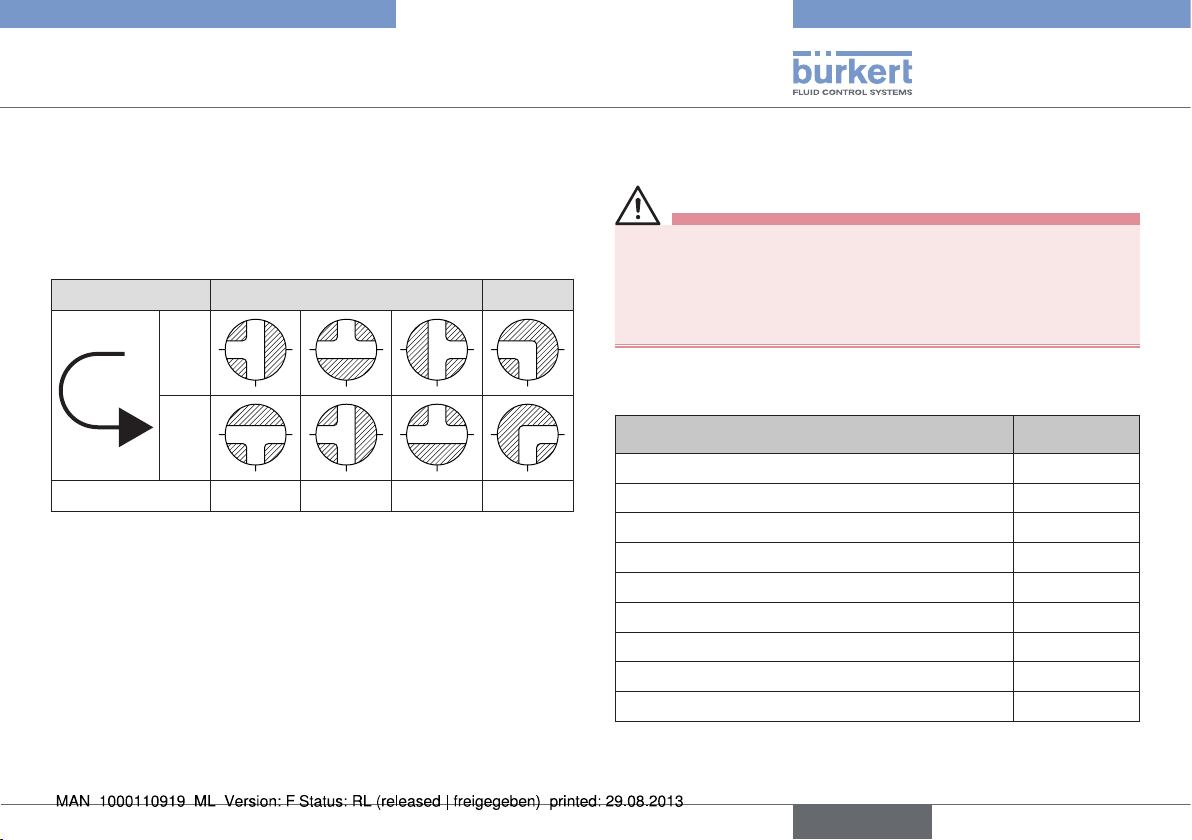
8.3. Functions
The ball valves are available in 2-way or 3-way design. The 3-way
designs are available with the following functions:
8.3.1. Switching positions
Ball bore T L
Position
0°
90°
Switching position
T1 T2 T3 L4
9. SPARE PARTS
CAUTION!
Risk of injury and / or damage by the use of incorrect parts!
Incorrect accessories and unsuitable spare parts may cause
injuries and damage the device and the surrounding area.
• Use original accessories and original spare parts from Bürkert
only.
Wearing part-sets for the three-part ball valve of type 2654:
Wearing part-set Order No.
Wearing part-set DN 15, VL-521 1/2" 789821
Wearing part-set DN 20, VL-501, VL-521 3/4" 789822
Wearing part-set DN 25, VL-501, VL-521 1" 789823
Wearing part-set DN 32, VL-501, VL-521 1 1/4" 789824
Wearing part-set DN 40, VL-501, VL-521 1 1/2" 789825
Wearing part-set DN 50, VL-501, VL-521 2" 789826
Wearing part-set DN 65, VL-501, VL-521 2 1/2" 789827
Wearing part-set DN 80, VL-501, VL-521 3" 789828
Wearing part-set DN 100, VL-501, VL-521 4" 789829
english
11
Page 12
Types 2651, 2654, 2660,
TKU 001
Maintenance, Troubleshooting
10. MAINTENANCE,
TROUBLESHOOTING
10.1. Maintenance Work
The ball valves are maintenance-free when operated according to the
instructions indicated in this manual.
11. PACKAGING, TRANSPORT,
STORAGE, DISPOSAL
NOTE!
Transport damages!
Inadequately protected equipment may be damaged during transport.
• During transportation protect the device against wet and dirt in
shock-resistant packaging.
• Avoid exceeding or dropping below the allowable storage
temperature.
• Protect the pneumatic connections from damage by placing caps
on them.
Incorrect storage may damage the device.
• Store the device in a dry and dust-free location!
• Storage temperature. -40 ... +55 °C.
Damage to the environment caused by device components
contaminated with media.
• Dispose of the device and packaging in an environmentally
friendly manner.
• Observe applicable regulations on disposal and the environment.
• Observe national waste disposal regulations.
12
english
Page 13

Typ 2651, 2654, 2660, TKU 001
Inhaltsverzeichnis
1. DIE BEDIENUNGSANLEITUNG ............................................................14
1.1. Darstellungsmittel ...........................................................................14
2. BESTIMMUNGSGEMÄSSE VERWENDUNG ...................................15
2.1. Beschränkungen ............................................................................15
2.2. Vorhersehbarer Fehlgebrauch .....................................................15
3. GRUNDLEGENDE SICHERHEITSHINWEISE ................................. 16
4. ALLGEMEINE HINWEISE .......................................................................... 17
4.1. Kontaktadresse ...............................................................................17
4.2. Gewährleistung...............................................................................17
4.3. Informationen im Internet ..............................................................17
5. SYSTEMBESCHREIBUNG ....................................................................... 17
5.1. Vorgesehener Einsatzbereich ......................................................17
5.2. Funktionen........................................................................................17
6. TECHNISCHE DATEN ................................................................................ 18
6.1. Betriebsbedingungen ....................................................................18
6.2. Allgemeine Technische Daten .....................................................18
7. INSTALLATION ............................................................................................... 19
7.1. Sicherheitshinweise .......................................................................19
7.2. Einbau in die Rohrleitung .............................................................20
8. BEDIENUNG UND FUNKTION .............................................................. 20
8.1. Sicherheitshinweise .......................................................................20
8.2. Bedienung des Kugelhahns .........................................................20
8.3. Funktionen........................................................................................21
9. ERSATZTEILE ................................................................................................. 21
10. WARTUNG, FEHLERBEHEBUNG....................................................... 22
10.1. Wartungsarbeiten ........................................................................22
11. VERPACKUNG, TRANSPORT, LAGERUNG,
ENTSORGUNG .................................................................................................... 22
deutsch
13
Page 14

Typ 2651, 2654, 2660, TKU 001
Die Bedienungsanleitung
1. DIE BEDIENUNGSANLEITUNG
Die Bedienungsanleitung beschreibt den gesamten Lebenszyklus
des Gerätes. Bewahren Sie diese Anleitung so auf, dass sie für jeden
Benutzer gut zugänglich ist und jedem neuen Eigentümer des Gerätes
wieder zur Verfügung steht.
Die Bedienungsanleitung enthält wichtige Informationen zur
Sicherheit!
Das Nichtbeachten dieser Hinweise kann zu gefährlichen Situationen führen.
• Die Bedienungsanleitung muss gelesen und verstanden werden.
1.1. Darstellungsmittel
GEFAHR!
Warnt vor einer unmittelbaren Gefahr!
• Bei Nichtbeachtung sind Tod oder schwere Verletzungen die
Folge.
WARNUNG!
Warnt vor einer möglicherweise gefährlichen Situation!
• Bei Nichtbeachtung drohen schwere Verletzungen oder Tod.
VORSICHT!
Warnt vor einer möglichen Gefährdung!
• Nichtbeachtung kann mittelschwere oder leichte Verletzungen
zur Folge haben.
HINWEIS!
Warnt vor Sachschäden!
• Bei Nichtbeachtung kann das Gerät oder die Anlage beschädigt
werden.
Bezeichnet wichtige Zusatzinformationen, Tipps und
Empfehlungen.
Verweist auf Informationen in dieser Bedienungsanleitung
oder in anderen Dokumentationen.
→ markiert einen Arbeitsschritt, den sie ausführen müssen.
14
deutsch
Page 15

Typ 2651, 2654, 2660, TKU 001
Bestimmungsgemäße Verwendung
2. BESTIMMUNGSGEMÄSSE
VERWENDUNG
Die Kugelhähne Typ 2651, 2654 und 2660 (im Folgenden allgemein
„Kugelhähne“) sind für den Anbau an pneumatische oder elektrische
Drehantrieben bestimmt. Sie können sowohl im Innenbereich als auch
im Außenbereich unter Einhaltung der zulässigen Einsatzbedingungen
eingesetzt werden.
Bei nicht bestimmungsgemäßem Einsatz der Kugelhähne
können Gefahren für Personen, Anlagen in der Umgebung
und die Umwelt entstehen.
• Die Kugelhähne sind zum Absperren von Medienströmen in
Industrieanwendungen vielfältig einsetzbar.
• Die Kugelhähne dürfen nur in Verbindung mit von Bürkert empfohlenen bzw. zugelassenen Fremdgeräten und -komponenten
eingesetzt werden.
• Für den Einsatz sind die in den Vertragsdokumenten und der Bedienungsanleitung spezifizierten zulässigen Daten und Betriebsbedingungen sowie die im Kapitel „5.1. Vorgesehener Einsatzbereich“
beschriebenen Einsatzbereiche zu beachten.
• Voraussetzungen für den sicheren und einwandfreien Betrieb sind
sachgemäßer Transport, sachgemäße Lagerung und Installation
sowie sorgfältige Bedienung und Instandhaltung.
• Setzen Sie die Kugelhähne nur bestimmungsgemäß ein.
2.1. Beschränkungen
Beachten Sie bei der Ausfuhr des Systems/Gerätes gegebenenfalls
bestehende Beschränkungen.
2.2. Vorhersehbarer Fehlgebrauch
• Betreiben Sie die Kugelhähne nur mit Medien, die Gehäuse- oder
Dichtwerkstoff nicht angreifen.
• Belasten Sie das Gehäuse nicht mechanisch (z. B. durch Ablage
von Gegenständen oder als Trittstufe).
• Nehmen Sie keine äußerlichen Veränderungen an dem Gehäuse vor.
deutsch
15
Page 16

Typ 2651, 2654, 2660, TKU 001
Grundlegende Sicherheitshinweise
3. GRUNDLEGENDE
SICHERHEITSHINWEISE
Diese Sicherheitshinweise berücksichtigen keine:
• Zufälligkeiten und Ereignisse, die bei Montage, Betrieb und Wartung
der Geräte auftreten können.
• Ortsbezogenen Sicherheitsbestimmungen, für deren Einhaltung,
auch in Bezug auf das Montagepersonal, der Betreiber verantwortlich ist.
WARNUNG!
Unbeabsichtigtes Betätigen oder unzulässige Beeinträchtigung können zu allgemeinen Gefahrensituationen bis hin
zur Körperverletzung führen.
Zum Schutz vor Verletzungen ist zu beachten:
• Dass die Anlage nicht unbeabsichtigt betätigt werden kann.
• Installations- und Instandhaltungsarbeiten dürfen nur von autorisiertem Fachpersonal mit geeignetem Werkzeug ausgeführt
werden.
• Nach einer Unterbrechung der elektrischen oder pneumatischen
Versorgung ist ein definierter oder kontrollierter Wiederanlauf
des Prozesses zu gewährleisten.
• Das Gerät darf nur in einwandfreiem Zustand und unter Beachtung der Bedienungsanleitung betrieben werden.
• Für die Einsatzplanung und den Betrieb des Gerätes müssen
die allgemeinen Regeln der Technik eingehalten werden.
GEFAHR!
Gefahr durch hohen Druck!
• Bei Eingriffen in die Anlage besteht akute Verletzungsgefahr.
• Schalten Sie den Druck ab und entlüften Sie die Leitungen,
bevor Sie Leitungen und Ventile lösen!
VORSICHT!
Für die Einsatzplanung und den Betrieb des Gerätes gelten
die allgemeinen Regeln der Technik!
• Beachten Sie die Regeln nicht, können Verletzungen entstehen
und/oder das Gerät, ggf. auch dessen Umgebung, können
beschädigt werden.
• Halten Sie die allgemeinen Regeln der Technik ein!
HINWEIS!
Die Kugelhähne wurden unter Einbeziehung der anerkannten
sicherheitstechnischen Regeln entwickelt und entsprechen dem
Stand der Technik. Trotzdem können Gefahren entstehen.
• Betreiben Sie die Kugelhähne nur in einwandfreiem Zustand und
unter Beachtung der Bedienungsanleitung.
Bei Nichtbeachtung dieser Bedienungsanleitung und ihrer Hinweise
sowie bei unzulässigen Eingriffen in das Gerät entfällt jegliche Haftung unsererseits, ebenso erlischt die Gewährleistung auf Geräte
und Zubehörteile!
16
deutsch
Page 17

Typ 2651, 2654, 2660, TKU 001
Allgemeine Hinweise
4. ALLGEMEINE HINWEISE
4.1. Kontaktadresse
Deutschland
Bürkert Fluid Control Systems
Sales Center
Chr.-Bürkert-Str. 13-17
D-74653 Ingelfingen
Tel. : +49 (0) 7940 - 10 91 111
Fax: +49 (0) 7940 - 10 91 448
E-mail: info@de.burkert.com
International
Die Kontaktadressen finden Sie auf den letzten Seiten der gedruckten
Bedienungsanleitung.
Außerdem im Internet unter: www.burkert.com
4.2. Gewährleistung
Voraussetzung für die Gewährleistung ist der bestimmungsgemäße Gebrauch des Gerätes unter Beachtung der spezifizierten
Einsatzbedingungen.
4.3. Informationen im Internet
Bedienungsanleitungen und Datenblätter zum Typ 2651, 2654, 2660
und TKU 001 finden Sie im Internet unter: www.buerkert.de
5. SYSTEMBESCHREIBUNG
5.1. Vorgesehener Einsatzbereich
Die Kugelhähne sind zum Absperren von Medienströmen in Industrieanwendungen vielfältig einsetzbar.
Sie sind besonders geeignet für Einsatzbedingungen, die hohe Anforderungen in den Bereichen der thermischen Belastung stellen, sowie
für Anwendungen mit aggressiven Medien.
5.2. Funktionen
Die Kugelhähne zum Absperren von Medienströmen stehen in verschiedenen Baugrößen zur Verfügung. Sie sind mit einer mechanischen
Schnittstelle nach ISO 5211 versehen. Diese Schnittstelle dient zur
Montage eines pneumatischen oder elektrischen Drehantriebs auf die
Kugelhähne.
Auf Anfrage können die Kugelhähne komplett mit pneumatischem Antrieb (Typen 2652, 2655, 8805) oder elektrischem
Antrieb (Typ 8804) geliefert werden.
deutsch
17
Page 18

Typ 2651, 2654, 2660, TKU 001
Technische Daten
6. TECHNISCHE DATEN
6.1. Betriebsbedingungen
Zulässigen Temperaturen
Umgebungstemperatur: Edelstahlgehäuse -10 … +80 °C
Messinggehäuse -20 … +80 °C
Mediumstemperatur: Edelstahlgehäuse -10 … +100 °C
Messinggehäuse -20 … +100 °C
Medien: Aggressive, neutrale gasförmige und
flüssige Medien und Dämpfe
Druckbereiche: 0 … 100 bar (je nach Ausführung)
6.2. Allgemeine Technische Daten
6.2.1. Mechanische Daten
Gehäusematerial: Edelstahl 1.4401; Messing vernickelt
Dichtungsmaterial: PTFE
6.2.2. Druck-Temperatur Diagramme,
2/2-Wege und 3/2-Wege Kugelhähne
50
40
30
20
Druck [bar]
10
0
-20 1201008060400 20 140160
Bild 1: Druck-Temperatur Diagramm / Messinggehäuse
40 bar
30 bar
25 bar
16 bar
10 bar
Temperatur [°C]
18
deutsch
Page 19

Typ 2651, 2654, 2660, TKU 001
Installation
100 bar
63 bar
7. INSTALLATION
7.1. Sicherheitshinweise
GEFAHR!
Verletzungsgefahr durch hohen Druck in der Anlage!
Bei Eingriffen in die Anlage besteht akute Verletzungsgefahr.
• Schalten Sie den Druck ab und entlüften Sie die Leitungen,
bevor Sie Leitungen und Ventile lösen!
40 bar
Druck [bar]
16 bar
0 bar
Temperatur [°C]
100400
200 230
Bild 2: Druck-Temperatur Diagramm / Edelstahlgehäuse
WARNUNG!
Verletzungsgefahr durch unsachgemäße Installation!
Nicht sachgemäße Installationen können zu Verletzungen, sowie
Schäden am Gerät und seiner Umgebung führen.
• Diese Arbeiten dürfen nur durch autorisiertes Fachpersonal und
mit geeignetem Werkzeug durchgeführt werden!
Verletzungsgefahr durch unbeabsichtigte Betätigung!
Durch unbeabsichtigtes Betätigen der Anlage können Gefahrensituationen entstehen.
• Verhindern Sie durch geeignete Maßnahmen, dass die Anlage
unbeabsichtigt betätigt werden kann.
deutsch
19
Page 20

Typ 2651, 2654, 2660, TKU 001
Bedienung und Funktion
7.2. Einbau in die Rohrleitung
Vorgehensweise:
→ Prüfen Sie, ob sich die mit dem Kugelhahn zu verbindenden Rohre
auf einem Niveau befinden. Damit vermeiden Sie mechanische
Spannungen auf die Verschraubung.
→ Verschrauben Sie den Kugelhahn mit der Rohrleitung.
→ Achten Sie auf festen Sitz des Kugelhahns in der Rohrleitung, um
die entsprechende Dichtheit zu gewährleisten.
8. BEDIENUNG UND FUNKTION
8.1. Sicherheitshinweise
WARNUNG!
Gefahr durch unsachgemäßen Bedienung!
Nicht sachgemäße Bedienung kann zu Verletzungen, sowie
Schäden am Gerät und seiner Umgebung führen.
• Das Bedienungspersonal muss den Inhalt der Bedienungsanleitung kennen und verstanden haben.
• Die Sicherheitshinweise und die Bestimmungsgemäße Verwendung müssen beachtet werden.
• Nur ausreichend geschultes Personal darf die Anlage/das Gerät
bedienen.
8.2. Bedienung des Kugelhahns
Die Kugelhähne können über die mechanische Schnittstelle nach
ISO 5211 mit einem pneumatischen (z. B. Typ 2050 oder 2051)
oder elektrischen Drehantrieb (z. B. Typen 3003, 3004 oder 3005)
verbunden werden.
20
deutsch
Page 21

Typ 2651, 2654, 2660, TKU 001
Ersatzteile
8.3. Funktionen
Die Kugelhähne werden in 2-Wege oder 3-Wege Ausführung angeboten. Die 3-Wege Ausführungen stehen mit folgenden Funktionen
zur Verfügung.
8.3.1. Schaltstellungen
Kugelbohrung T L
Position
0°
90°
Schaltstellung
T1 T2 T3 L4
9. ERSATZTEILE
VORSICHT!
Verletzungsgefahr, Sachschäden durch falsche Teile!
Falsches Zubehör und ungeeignete Ersatzteile können Verletzungen
und Schäden am Gerät und dessen Umgebung verursachen.
• Nur Originalzubehör sowie Originalersatzteile der Firma Bürkert
verwenden.
Verschleißteilsätze für 3-teiligen Kugelhahn Typ 2654:
Verschleißteilsätze Bestell-Nr.
Verschleißteilsatz DN15, VL-521 1/2" 789821
Verschleißteilsatz DN20, VL-501, VL-521 3/4" 789822
Verschleißteilsatz DN25, VL-501, VL-521 1" 789823
Verschleißteilsatz DN32, VL-501, VL-521 1 1/4" 789824
Verschleißteilsatz DN40, VL-501, VL-521 1 1/2" 789825
Verschleißteilsatz DN50, VL-501, VL-521 2" 789826
Verschleißteilsatz DN65, VL-501, VL-521 2 1/2" 789827
Verschleißteilsatz DN80, VL-501, VL-521 3" 789828
Verschleißteilsatz DN100, VL-501, VL-521 4" 789829
deutsch
21
Page 22
Typ 2651, 2654, 2660, TKU 001
Wartung, Fehlerbehebung
10. WARTUNG,
FEHLERBEHEBUNG
10.1. Wartungsarbeiten
Die Kugelhähne sind bei Betrieb entsprechend den in dieser Anleitung
angegebenen Anweisungen wartungsfrei.
11. VERPACKUNG, TRANSPORT,
LAGERUNG, ENTSORGUNG
HINWEIS!
Transportschäden!
Unzureichend geschützte Geräte können durch den Transport
beschädigt werden.
• Gerät vor Nässe und Schmutz geschützt in einer stoßfesten
Verpackung transportieren.
• Eine Über- bzw. Unterschreitung der zulässigen Lagertemperatur vermeiden.
• Pneumatische Anschlüsse mit Schutzkappen vor Beschädigungen
schützen.
Falsche Lagerung kann Schäden am Gerät verursachen.
• Gerät trocken und staubfrei lagern!
• Lagertemperatur. -40 … +55 °C.
Umweltschäden durch von Medien kontaminierte Geräteteile.
• Entsorgen Sie das Gerät und die Verpackung umweltgerecht.
• Geltende Entsorgungsvorschriften und Umweltbestimmungen
einhalten.
• Die nationalen Abfallbeseitigungsvorschriften beachten.
22
deutsch
Page 23

Types 2651, 2654, 2660,
TKU 001
Sommaire
1. LES INSTRUCTIONS DE SERVICE ..................................................... 24
1.1. Moyens de représentation ............................................................24
2. UTILISATION CONFORME.......................................................................25
2.1. Limitations ........................................................................................25
2.2. Mauvaise utilisation prévisible .....................................................25
3. CONSIGNES DE SÉCURITÉ FONDAMENTALES ......................... 26
4. INDICATIONS GÉNÉRALES .................................................................... 27
4.1. Adresse ............................................................................................27
4.2. Garantie légale ................................................................................27
4.3. Informations sur Internet ...............................................................27
5. DESCRIPTION DU SYSTÈME ................................................................27
5.1. Utilisation prévue ............................................................................27
5.2. Fonctions ..........................................................................................27
6. CARACTÉRISTIQUES TECHNIQUES ................................................28
6.1. Conditions d'exploitation ..............................................................28
6.2. Caractéristiques techniques générales ....................................28
7. INSTALLATION ............................................................................................... 29
7.1. Consignes de sécurité ..................................................................29
7.2. Montage dans la tuyauterie ..........................................................30
8. UTILISATION ET FONCTIONNEMENT...............................................30
8.1. Consignes de sécurité ..................................................................30
8.2. Utilisation du robinet à boisseau sphérique .............................30
8.3. Fonctions ..........................................................................................31
9. PIÈCES DE RECHANGE ........................................................................... 31
10. MAINTENANCE, DÉPANNAGE ............................................................32
10.1. Travaux de maintenance .............................................................32
11. EMBALLAGE, TRANSPORT, STOCKAGE, ELIMINATION ...... 32
français
23
Page 24

Types 2651, 2654, 2660,
TKU 001
Les instructions de service
1. LES INSTRUCTIONS DE
SERVICE
Les instructions de service décrivent le cycle de vie complet de l’appareil. Conservez ces instructions de sorte qu’elles soient accessibles
à tout utilisateur et à disposition de tout nouveau propriétaire.
Les instructions de service contiennent des informations
importantes sur la sécurité !
Le non-respect de ces consignes peut entraîner des situations
dangereuses.
• Les instructions de service doivent être lues et comprises.
1.1. Moyens de représentation
DANGER !
Met en garde contre un danger imminent !
• Le non-respect peut entraîner la mort ou de graves blessures.
AVERTISSEMENT !
Met en garde contre une situation éventuellement dangereuse !
• Risque de blessures graves, voire la mort en cas de non-respect.
ATTENTION !
Met en garde contre un risque possible !
• Le non-respect peut entraîner des blessures légères ou de
moyenne gravité.
REMARQUE !
Met en garde contre des dommages matériels !
• L’appareil ou l’installation peut être endommagé(e) en cas de
non-respect.
Désigne des informations supplémentaires importantes, des
conseils et des recommandations d’importance.
Renvoie à des informations dans ces instructions de service
ou dans d’autres documentations.
→ identifie une opération que vous devez effectuer.
24
français
Page 25

Types 2651, 2654, 2660,
TKU 001
Utilisation conforme
2. UTILISATION CONFORME
Les robinets à boisseau sphérique du type 2651, 2654 ou 2660
(ci-après « Robinets à boisseau sphérique ») sont conçus pour un
branchement sur les servomoteurs pneumatiques ou électriques. Ils
peuvent être utilisés à l’intérieur comme à l’extérieur en respectant les
conditions d’utilisation autorisées.
L’utilisation non conforme des robinets à boisseau sphérique
peut présenter des dangers pour les personnes, les installations proches et l’environnement.
• Les robinets à boisseau sphérique ont été conçus pour arrêter
les flux de fluides comme on les rencontrent lors de la réalisation
d’applications industrielles.
• Les robinets à boisseau sphérique doivent uniquement être utilisés
en liaison avec les appareils et composants étrangers recommandés ou agréés par Bürkert.
• L’utilisation doit se faire dans le respect des données admissibles
spécifiées dans les documents contractuels et les instructions de
service ainsi que des conditions d’exploitation et des utilisations
prévues décrites au chapitre „5.1. Utilisation prévue“.
• Les conditions pour l’utilisation sûre et parfaite sont un transport, un
stockage et une installation dans les règles ainsi qu’une parfaite
utilisation et maintenance.
• N’utilisez jamais les robinets à boisseau sphérique pour un
usage autre que l’usage prévu.
2.1. Limitations
Lors de l’exportation du système/de l’appareil, veuillez respecter les
limitations éventuelles existantes.
2.2. Mauvaise utilisation prévisible
• Utilisez uniquement les robinets à boisseau sphérique avec les fluides
qui n’attaquent pas les matériaux du corps et du joint.
• Ne soumettez pas le corps à des contraintes mécaniques (par ex. en
y déposant des objets ou en l’utilisant comme marche).
• N’apportez pas de modifications à l’extérieur du corps.
français
25
Page 26

Types 2651, 2654, 2660,
TKU 001
Consignes de sécurité fondamentales
3. CONSIGNES DE SÉCURITÉ
FONDAMENTALES
Ces consignes de sécurité ne tiennent pas compte :
• Des hasards et des événements pouvant survenir lors du montage,
de l'exploitation et de la maintenance des appareils.
• Des prescriptions de sécurité locales que l’exploitant est tenu de
faire respecter par le personnel chargé du montage.
AVERTISSEMENT !
L’actionnement involontaire ou l’intervention non autorisée
peut entraîner des situations dangereuses, voire des blessures
corporelles.
Pour prévenir les blessures, respectez ce qui suit :
• L’installation ne peut pas être actionnée par inadvertance.
• Les travaux d’installation et de maintenance doivent être
effectués uniquement par des techniciens qualifiés et habilités
disposant de l’outillage approprié.
• Après une interruption de l’alimentation électrique ou du fluide,
un redémarrage défini ou contrôlé du process doit être garanti.
• L’appareil doit être utilisé uniquement en parfait état et en respectant les instructions de service.
• Les règles générales de la technique sont à appliquer pour
l’opérationnel et l’utilisation de l’appareil.
DANGER !
Danger dû à la haute pression !
• Il y a risque important de blessures lors d’interventions sur
l'installation.
• Avant de desserrer les conduites et les vannes, dépressurisez
l’installation et purgez l’air des conduites !
ATTENTION !
Les règles générales de la technique sont d'application pour
planifier l’utilisation et utiliser l’appareil !
• Si ces règles ne sont pas respectées, il peut s’ensuivre des blessures et/ou des dommages sur l’appareil ou son environnement.
• Respectez les règles générales de la technique !
REMARQUE !
Les robinets à boisseau sphérique ont été développés en tenant
compte des règles de technique de sécurité reconnues et correspondent à l’état actuel de la technique. Néanmoins, des risques
peuvent se présenter.
• Utilisez l’appareil uniquement en parfait état et en respectant les
instructions de service.
Le non-respect de ces instructions de service avec ses consignes
ainsi que les interventions non autorisées sur l’appareil excluent
toute responsabilité de notre part et entraînent la nullité de la
garantie légale concernant les appareils et les accessoires !
26
français
Page 27

Types 2651, 2654, 2660,
TKU 001
Indications générales
4. INDICATIONS GÉNÉRALES
4.1. Adresse
Allemagne
Bürkert Fluid Control Systems
Sales Center
Chr.-Bürkert-Str. 13-17
D-74653 Ingelfingen
Tél. : +49 (0)7940 - 10 91 111
Fax : +49 (0)7940 - 10 91 448
E-mail : info@de.burkert.com
International
Les adresses se trouvent aux dernières pages des instructions de
service imprimées. Egalement sur internet sous : www.burkert.com
4.2. Garantie légale
La condition pour bénéficier de la garantie légale est l’utilisation
conforme de l’appareil dans le respect des conditions d’utilisation
spécifiées.
4.3. Informations sur Internet
Vous trouverez les instructions de service et les fiches techniques
concernant le type 2651, 2654, 2660 et TKU 001 sur Internet
sous : www.buerkert.fr
5. DESCRIPTION DU SYSTÈME
5.1. Utilisation prévue
Les robinets à boisseau sphérique ont été conçus pour arrêter les flux
de fluides comme on les rencontrent lors de la réalisation d’applications industrielles.
Il sont particulièrement adaptés aux conditions d’utilisation très exigeantes dans les domaines des charges thermiques ou vibratoires
ainsi qu’aux applications faisant usage de fluides agressifs.
5.2. Fonctions
Différents modèles de robinets à boisseau sphérique sont disponibles
pour l’arrêt des flux de fluides. Ils sont munis d’une interface mécanique
selon ISO 5211. Cette interface sert au montage d’un entraînement
rotatif pneumatique ou électrique sur les robinets à boisseau sphérique.
Sur demande, les robinets à boisseau sphérique peuvent être
livrés avec un entraînement pneumatique (Types 2652, 2655,
8805) ou avec un entraînement électrique (Type 8804).
français
27
Page 28

Types 2651, 2654, 2660,
TKU 001
Caractéristiques techniques
6. CARACTÉRISTIQUES
TECHNIQUES
6.1. Conditions d'exploitation
Températures admissibles
Température ambiante : Corps en acier inoxydable -10 – +80 °C
Corps en laiton : -20 – +80 °C
Température du fluide : Corps en acier inoxydable -10 – +100 °C
Corps en laiton : -20 – +100 °C
Fluides : fluides et vapeurs gazeux et liquides,
agressifs et neutres
Plage de pression : 0 – 100 bars (selon le modèle)
6.2. Caractéristiques techniques
générales
6.2.1. Caractéristiques mécaniques
Matériau du boîtier : Acier inoxydable 1.4401 ; laiton nickelé
Matériau d'étanchéité : PTFE
6.2.2. Diagrammes pression-température,
robinets à boisseau sphérique
2/2 voies et 3/2 voies
50
40
30
20
Pression [bars]
10
0
-20 1201008060400 20 140160
Fig. 1 : Diagrammes pression-température / corps en laiton
40 bar
30 bar
25 bar
16 bar
10 bar
Température [°C]
28
français
Page 29

Types 2651, 2654, 2660,
TKU 001
Installation
7. INSTALLATION
7.1. Consignes de sécurité
100 bar
63 bar
40 bar
Pression [bars]
16 bar
0 bar
Température [°C]
100400
200 230
Fig. 2 : Diagrammes pression-température / corps en acier
inoxydable
français
DANGER !
Risque de blessures dû à la présence de haute pression dans
l'installation !
Il y a risque important de blessures lors d’interventions sur l'installation.
• Avant de desserrer les conduites et les vannes, dépressurisez
l’installation et purgez l’air des conduites !
AVERTISSEMENT !
Risque de blessures dû à un montage non conforme !
Les installations non conformes peuvent occasionner des blessures
et endommager l’appareil et son environnement.
• Ces travaux doivent être effectués uniquement par des techniciens
qualifiés et habilités disposant de l’outillage approprié !
Danger dû à l’actionnement involontaire !
Des situations dangereuses peuvent se présenter en cas de
manoeuvres accidentelles.
• Evitez l’actionnement involontaire de l’installation par des
mesures appropriées.
29
Page 30

Types 2651, 2654, 2660,
TKU 001
Utilisation et fonctionnement
7.2. Montage dans la tuyauterie
Procédure à suivre :
→ Assurez-vous que les tuyaux à raccorder se trouvent au même
niveau que le robinet à boisseau sphérique. Vous évitez ainsi des
tensions mécaniques sur le raccord fileté.
→ Vissez le robinet à boisseau sphérique sur la conduite.
→ Veillez à positionner correctement le robinet à boisseau sphérique
sur la conduite afin de garantir l’étanchéité de l’installation.
8. UTILISATION ET
FONCTIONNEMENT
8.1. Consignes de sécurité
AVERTISSEMENT !
Danger dû à une utilisation non conforme !
Une utilisation non conforme peut entraîner des blessures et
endommager l'appareil et son environnement.
• Les opérateurs doivent connaître le contenu des instructions de
service et les avoir comprises.
• Respectez les consignes de sécurité et l'utilisation conforme.
• L’appareil/l'installation doit uniquement être utilisé par un personnel
suffisamment formé.
8.2. Utilisation du robinet à boisseau
sphérique
L’interface mécanique selon ISO 5211 permet de relier les robinets
à boisseau sphérique avec un servomoteur pneumatique (par ex. du
type 2050 ou 2051) ou avec un servomoteur électrique (par ex. du
type 3003, 3004 ou 3005).
30
français
Page 31

Types 2651, 2654, 2660,
TKU 001
Pièces de rechange
8.3. Fonctions
Les robinets à boisseau sphérique sont disponibles en version à 2 ou
3 voies. Les modèles 3 voies offrent les fonctions suivantes :
8.3.1. Positions de commutation
Perçage de
boisseau
sphérique
Position
Position de
commutation
0°
90°
T1 T2 T3 L4
T L
9. PIÈCES DE RECHANGE
ATTENTION !
Risque de blessures, de dommages matériels dus à de mauvaises pièces !
De mauvais accessoires ou des pièces de rechange inadaptées
peuvent provoquer des blessures et endommager l‘appareil ou
son environnement.
• Utiliser uniquement des accessoires et des pièces de rechange
d‘origine de la société Bürkert.
Jeux de pièces d’usure pour robinet à boisseau sphérique 3
pièces types 2654 :
Jeux de pièces d‘usure N° Réf.
Jeu de pièces d‘usure DN 15, VL-521 1/2" 789821
Jeu de pièces d‘usure DN 20, VL-501, VL-521 3/4" 789822
Jeu de pièces d‘usure DN 25, VL-501, VL-521 1" 789823
Jeu de pièces d‘usure DN 32, VL-501, VL-521 1 1/4" 789824
Jeu de pièces d‘usure DN 40, VL-501, VL-521 1 1/2" 789825
Jeu de pièces d‘usure DN 50, VL-501, VL-521 2" 789826
Jeu de pièces d‘usure DN 65, VL-501, VL-521 2 1/2" 789827
Jeu de pièces d‘usure DN 80, VL-501, VL-521 3" 789828
Jeu de pièces d‘usure DN 100, VL-501, VL-521 4" 789829
français
31
Page 32

Types 2651, 2654, 2660,
TKU 001
Maintenance, dépannage
10. MAINTENANCE, DÉPANNAGE
10.1. Travaux de maintenance
Les robinets à boisseau sphérique ne nécessitent pas d’entretien dans
la mesure où les présentes instructions sont respectées.
11. EMBALLAGE, TRANSPORT,
STOCKAGE, ELIMINATION
REMARQUE !
Dommages dus au transport !
Les appareils insuffisamment protégés peuvent être endommagés
pendant le transport.
• Transportez l'appareil à l'abri de l'humidité et des impuretés et
dans un emballage résistant aux chocs.
• Évitez le dépassement vers le haut ou le bas de la température
de stockage admissible.
• Protégez les raccords pneumatiques des dommages en utilisant
des capuchons de protection.
Un mauvais stockage peut endommager l’appareil.
• Stockez l’appareil au sec et à l’abri des poussières !
• Température de stockage : -40 ... +55 °C.
Dommages à l’environnement causés par des pièces d’appareil
contaminées par des fluides.
• Eliminez l’appareil et l’emballage dans le respect de
l’environnement.
• Respectez les prescriptions en matière d’élimination des déchets
et de protection de l’environnement en vigueur.
• Respectez les prescriptions nationales en matière d’élimination des
déchets.
32
français
Page 33

Page 34

www.burkert.com
 Loading...