

Page 1
Type 8026 - 8036 - SE36
Flowmeter and Flow transmitter
Durchfluss-Messgerät und Durchfluss-Transmitter
Débitmètre et transmetteur de débit
Operating Instructions
Bedienungsanleitung
Manuel d‘utilisation
Page 2

We reserve the right to make technical changes without notice.
Technische Änderungen vorbehalten.
Sous réserve de modification technique.
© Bürkert SAS, 2009 - 2016
Operating Instructions 1603/02_EU-ML 00561367 / Original_FR
Page 3

Type 8026 - 8036 - SE36
Contents
1 ABOUT THIS MANUAL .....................................................................................................................................................................7
1.1 Definition of the word "device" .......................................................................................................................................7
1.2 Validity of the manual ..........................................................................................................................................................7
1.3 Symbols used ..........................................................................................................................................................................7
2 INTENDED USE ....................................................................................................................................................................................8
3 BASIC SAFETY INFORMATION ....................................................................................................................................................9
4 GENERAL INFORMATION .............................................................................................................................................................10
4.1 Manufacturer's address and international contacts .........................................................................................10
4.2 Warranty conditions ...........................................................................................................................................................10
4.3 Information on the Internet ............................................................................................................................................10
5 DESCRIPTION ....................................................................................................................................................................................11
5.1 Area of application .............................................................................................................................................................11
5.2 General description ...........................................................................................................................................................11
5.2.1 Construction of the 8026 .................................................................................................................11
5.2.2 Construction of the SE36 ................................................................................................................12
5.2.3 Construction of the 8036 .................................................................................................................12
5.2.4 Construction of the SE36 with sensor-fitting S070 or S077 ..................................................12
5.3 Description of the name plate .....................................................................................................................................13
5.4 Available versions of type 8026 ..................................................................................................................................14
5.5 Available versions of the transmitter SE36 ..........................................................................................................15
6 TECHNICAL DATA .............................................................................................................................................................................16
6.1 Conditions of use ................................................................................................................................................................16
6.2 Conformity to standards and directives .................................................................................................................16
6.2.1 Conformities common to the 8026 and the SE36 .....................................................................16
6.2.2 Conformity to the pressure equipment directive .........................................................................16
6.3 Mechanical data ...................................................................................................................................................................17
6.4 Fluid data .................................................................................................................................................................................18
6.5 Electrical data .......................................................................................................................................................................19
English
3
Page 4

Type 8026 - 8036 - SE36
7 ASSEMBLY ...........................................................................................................................................................................................20
7.1 Safety instructions .............................................................................................................................................................20
7.2 Removing the cover ...........................................................................................................................................................20
7.3 Mounting the cover ............................................................................................................................................................21
7.4 Mounting the display module .......................................................................................................................................21
7.5 Removing the display module .....................................................................................................................................22
8 INSTALLATION AND WIRING ......................................................................................................................................................23
8.1 Safety instructions .............................................................................................................................................................23
8.2 Installation of a 8026 on a pipe ...................................................................................................................................24
8.2.1 Install the fitting S020 in the pipe ..................................................................................................24
8.2.2 Install the flowmeter 8026 into the fitting S020 ........................................................................25
8.2.3 Complete the installation of the 8026 ...........................................................................................25
8.3 Installation of a 8036 on a pipe ...................................................................................................................................26
8.3.1 Install the sensor-fitting S030 in the pipe .................................................................................... 26
8.3.2 Assemble the flow transmitter SE36 on the sensor-fitting S030 ...........................................26
8.3.3 Complete the installation of the 8036 ...........................................................................................27
8.4 Installation of a flow transmitter SE36 with sensor-fitting S070 or S077 in a pipe .......................27
8.4.1 Install the sensor-fitting S070 or S077 in a pipe ....................................................................... 27
8.4.2 Assemble the flow transmitter SE36 on the sensor-fitting S070 or S077 .......................... 28
8.4.3 Complete the installation of the flow transmitter SE36 with sensor-fitting
S070 or S077 .....................................................................................................................................28
8.5 Wiring .........................................................................................................................................................................................28
8.5.1 Electrical connections .......................................................................................................................29
8.5.2 Assembling the male or female connector (accessories: see chap. 11) ..............................29
8.5.3 Equipotentiality of the installation ...................................................................................................29
8.5.4 Wiring a version with a single M12 fixed connector and an NPN transistor
output and a current output .............................................................................................................31
8.5.5 Wiring a version with a single M12 fixed connector and two transistor out-
puts and one current output ............................................................................................................32
8.5.6 Wiring a version with two M12 fixed connectors and two transistor outputs
and two current outputs ....................................................................................................................34
9 ADJUSTMENT AND COMMISSIONING .................................................................................................................................37
9.1 Safety instructions .............................................................................................................................................................37
9.2 When switching on the device .....................................................................................................................................37
4
English
Page 5

Type 8026 - 8036 - SE36
9.3 Knowing the operating levels .......................................................................................................................................38
9.4 Using the navigation button ..........................................................................................................................................39
9.5 Using the dynamic functions ........................................................................................................................................40
9.6 Entering a numerical value (example) .....................................................................................................................41
9.7 Browsing in a menu (example) ...................................................................................................................................41
9.8 Knowing the icons and LEDs .......................................................................................................................................42
9.9 Knowing the Process level ............................................................................................................................................43
9.10 Accessing the Configuration level .............................................................................................................................44
9.11 Knowing the structure of the Configuration menus ........................................................................................45
9.12 Knowing the menu Parameter .....................................................................................................................................49
9.12.1 Transferring data from one device to another .............................................................................. 49
9.12.2 Modifying the access code of menu "Param" ..............................................................................50
9.12.3 Restoring the default parameters of the Process level and the outputs ............................... 50
9.12.4 Setting the data displayed in Process level .................................................................................51
9.12.5 Choosing the units for the totalizers displayed in Process level .............................................53
9.12.6 Displaying the lowest and highest values measured .................................................................53
9.12.7 Setting the contrast and the backlight of the display ................................................................54
9.12.8 Defining the connection mode of the outputs .............................................................................54
9.12.9 Setting the parameters of the current outputs ............................................................................55
9.12.10 Setting the parameters of the transistor outputs ........................................................................56
9.13 Knowing the menu Calibration ....................................................................................................................................58
9.13.1 Activating/deactivating the Hold function ..................................................................................... 58
9.13.2 Modifying the Calibration menu access code .............................................................................59
9.13.3 Resetting totalizer 1 or totalizer 2 respectively ............................................................................59
9.13.4 Adjusting the current outputs .......................................................................................................... 59
9.13.5 Entering the K-factor or determining it with Teach-In ................................................................60
9.14 Knowing the menu Diagnostic ....................................................................................................................................63
9.14.1 Modifying the Diagnostic menu access code ..............................................................................63
9.14.2 Monitoring the sensor input frequency .......................................................................................... 63
9.15 Knowing the menu Test ...................................................................................................................................................64
9.15.1 Modifying the Test menu access code .......................................................................................... 64
9.15.2 Checking the output functions ........................................................................................................64
9.15.3 Checking the outputs behaviour .....................................................................................................65
9.16 Knowing the menu Information ...................................................................................................................................66
English
5
Page 6

Type 8026 - 8036 - SE36
10 MAINTENANCE AND TROUBLESHOOTING .......................................................................................................................67
10.1 Safety instructions .............................................................................................................................................................67
10.2 Cleaning the device ...........................................................................................................................................................67
10.3 Solving problems ................................................................................................................................................................68
11 SPARE PARTS AND ACCESSORIES ......................................................................................................................................70
12 PACKAGING, TRANSPORT ..........................................................................................................................................................70
13 STORAGE ..............................................................................................................................................................................................70
14 DISPOSAL OF THE PRODUCT ..................................................................................................................................................71
6
English
Page 7
Type 8026 - 8036 - SE36
About this manual
1 ABOUT THIS MANUAL
This manual describes the entire lifecycle of the device. Please keep this manual in a safe place, accessible to all
users and any new owners.
This manual contains important safety information.
Failure to comply with these instructions can lead to hazardous situations. Pay attention in particular to the
chapters "Basic safety information" and "Intended use".
▶ Whatever the version of the device, this manual must be read and understood.
1.1 Definition of the word "device"
The word "device" used within this manual refers to the flowmeter type 8026, the flowmeter type 8036 or the
flow transmitter type SE36.
1.2 Validity of the manual
The manual is valid for the following devices:
• flowmeter 8026 from the version V2,
• flowmeter 8036 from the version V2,
• flow transmitter SE36 from the version V2.
These informations are available on the name plate, see chap. 5.3.
1.3 Symbols used
DANGER
Warns against an imminent danger.
▶ Failure to observe this warning can result in death or in serious injury.
WARNING
Warns against a potentially dangerous situation.
▶ Failure to observe this warning can result in serious injury or even death.
ATTENTION
Warns against a possible risk.
▶ Failure to observe this warning can result in substantial or minor injuries.
NOTE
Warns against material damage.
▶ Failure to observe this warning may result in damage to the device or system.
7
English
Page 8
Type 8026 - 8036 - SE36
About this manual
Indicates additional information, advice or important recommendations.
Refers to information contained in this manual or in other documents.
▶ Indicates an instruction to be carried out to avoid a danger, a warning or a possible risk.
→ Indicates a procedure to be carried out.
Indicates the result of a specific instruction.
2 INTENDED USE
Use of the device that does not comply with the instructions could present risks to people, nearby
installations and the environment.
Flowmeters 8026 and 8036 and flow transmitter SE36 associated with a sensor-fitting are intended to
measure the flow rate of liquids.
▶ Use this device in compliance with the characteristics and commissioning and use conditions specified in the
contractual documents and in the user manual.
▶ Never use this device for security applications.
▶ Protect this device against electromagnetic interference, ultraviolet rays and, when installed outdoors, the
effects of climatic conditions.
▶ Use this device only if in perfect working order.
▶ Requirements for the safe and proper operation of the device are proper transport, storage and installation, as
well as careful operation and maintenance.
▶ Only use the device as intended.
8
English
Page 9
Type 8026 - 8036 - SE36
Basic safety information
3 BASIC SAFETY INFORMATION
This safety information does not take into account:
• any contingencies or occurrences that may arise during installation, use and maintenance of the devices.
• the local safety regulations for which the operating company is responsible including the staff in charge of
installation and maintenance.
Danger due to electrical voltage.
▶ If a 12-36 V DC or a 14-36 V DC powered version is installed either in a wet environment or outdoors, all the
electrical voltages must be of max. 35 V DC.
▶ Disconnect the electrical power for all the conductors and isolate it before carrying out work on the system.
▶ Observe all applicable accident protection and safety regulations for electrical equipment.
Danger due to high pressure in the installation.
▶ Stop the circulation of fluid, cut off the pressure and drain the pipe before loosening the process connections.
Danger due to high temperatures of the fluid.
▶ Use safety gloves to handle the device.
▶ Stop the circulation of fluid and drain the pipe before loosening the process connections.
Danger due to the nature of the fluid.
▶ Respect the prevailing regulations on accident prevention and safety relating to the use of aggressive fluids.
Various dangerous situations
To avoid injury take care:
▶ not to use the device for the measurement of gas flow rates.
▶ not to use the device in explosive atmospheres.
▶ not to use the device in an environment incompatible with the materials it is made of.
▶ not to use fluid that is incompatible with the materials the device is made of.
▶ not to make any modifications to the device.
▶ not to subject the device to mechanical loads.
▶ to prevent any unintentional power supply switch-on.
▶ to carry out the installation and maintenance work by qualified and skilled staff with the appropriate tools.
▶ to guarantee a defined or controlled restarting of the process, after a power supply interruption.
▶ to observe the general technical rules when installing and using the device.
English
9
Page 10
Type 8026 - 8036 - SE36
Basic safety information
NOTE
The device may be damaged by the fluid in contact with.
▶ Systematically check the chemical compatibility of the component materials of the device and the fluids likely
to come into contact with it (for example: alcohols, strong or concentrated acids, aldehydes, alkaline compounds, esters, aliphatic compounds, ketones, halogenated aromatics or hydrocarbons, oxidants and chlorinated agents).
NOTE
Elements / Components sensitive to electrostatic discharges
▶ This device contains electronic components sensitive to electrostatic discharges. They may be damaged if
they are touched by an electrostatically charged person or object. In the worst case scenario, these components are instantly destroyed or go out of order as soon as they are activated.
▶ To minimise or even avoid all damage due to an electrostatic discharge, take all the precautions described in
standard EN 61340-5-1.
▶ Also ensure that you do not touch any of the live electrical components.
4 GENERAL INFORMATION
4.1 Manufacturer's address and international contacts
To contact the manufacturer of the device, use following address:
Bürkert SAS
Rue du Giessen
BP 21
F-67220 TRIEMBACH-AU-VAL
You may also contact your local Bürkert sales office.
The addresses of our international sales offices are available on the internet at:
www.burkert.com
4.2 Warranty conditions
The condition governing the legal warranty is the conforming use of the device in observance of the operating
conditions specified in this manual.
10
4.3 Information on the Internet
You can find the user manuals and technical data sheets regarding the types 8026, 8036 and SE36 at:
www.burkert.com
English
Page 11
C
Type 8026 - 8036 - SE36
Description
5 DESCRIPTION
5.1 Area of application
8026, 8036 and SE36 devices are intended to measure the flow rate of liquids:
• flowmeters 8026 and 8036 are used to measure the flow of neutral or slightly aggressive liquids,
• flow transmitter SE36 with sensor-fitting S070 or S077 is used to measure the flow rate of viscous liquids such
as honey or oil and which are free of solid particles.
Thanks to one or two fully adjustable transistor outputs, the device can be used to switch a solenoid valve,
activate an alarm and, thanks to one or two 4-20-mA current outputs, establish one or two control loops.
5.2 General description
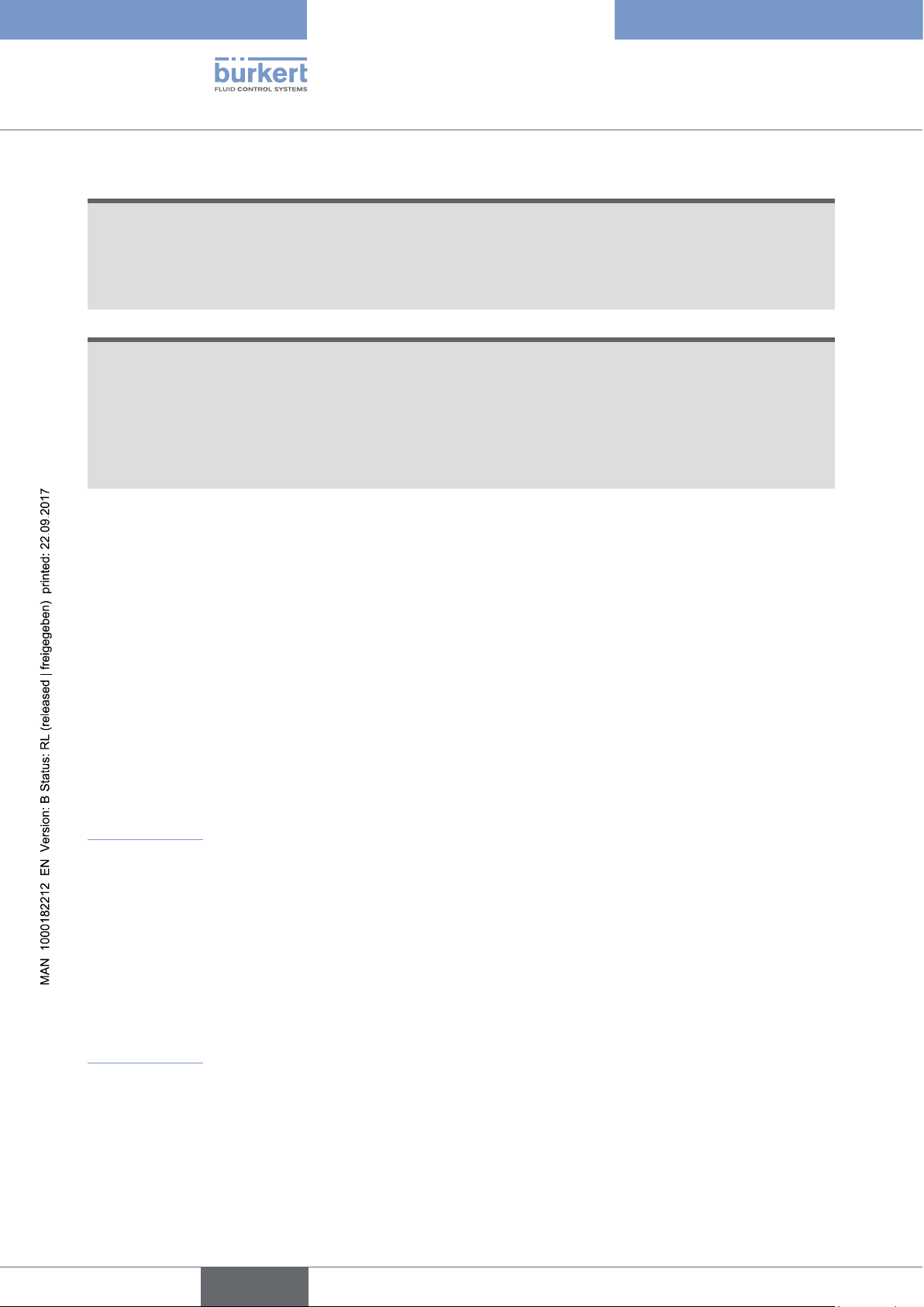
5.2.1 Construction of the 8026
The flowmeter 8026 comprises:
A: a paddle-wheel flow sensor, the rotation of which generates pulses.
Set in rotation by the flow, the 4 permanent magnets integrated in the vanes of the
paddle generate pulses, the frequency of which is proportional to the flow velocity
of the fluid. A conversion coefficient specific to each pipe (material and diameter) is
necessary to establish the flow rate value associated with the measurement.
The conversion coefficient (K-factor) expressed in pulses per litre is given in the user
manual for the fitting used.
B
B: an acquisition / conversion module for the process values measured:
• acquisition of the pulse frequency
• conversion of the frequency measured into flow rate units
C: an electrical housing which can include a display module. The display module
has a navigation button to read and/or configure the parameters of the device. The
A
display module is not delivered with all the versions of the flowmeter but is available
as accessory (see chap. 11).
11
English
Page 12
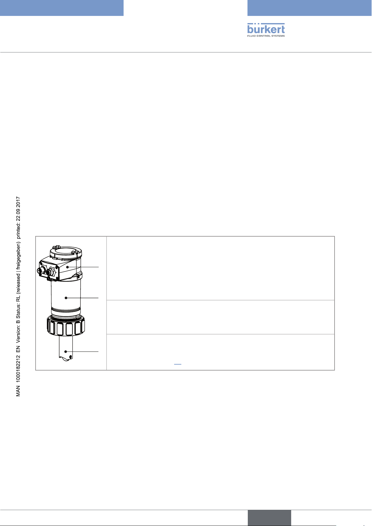
5.2.2 Construction of the SE36
B
A
B
S077
The flow transmitter SE36 comprises:
A: an acquisition / conversion module for the process values measured:
• acquisition of the pulse frequency
• conversion of the frequency measured into flow rate units
B: an electrical housing which can include a display module. The display module
has a navigation button to read and/or configure the parameters of the device. The
A
display module is not delivered with all the versions of the flowmeter but is available
as accessory (see chap. 11).
5.2.3 Construction of the 8036
The flowmeter 8036 comprises:
Type 8026 - 8036 - SE36
Description
A: an S030 sensor-fitting including the paddle-wheel flow sensor.
Set in rotation by the flow, the 4 permanent magnets integrated in the vanes of the
paddle generate pulses, the frequency of which is proportional to the flow velocity
of the fluid. A conversion coefficient specific to each pipe (material and diameter) is
necessary to establish the flow rate value associated with the measurement.
The conversion coefficient (K-factor) expressed in pulses per litre is given in the user
manual for the sensor-fitting used.
B: a flow transmitter SE36 (see chap. 5.2.2)
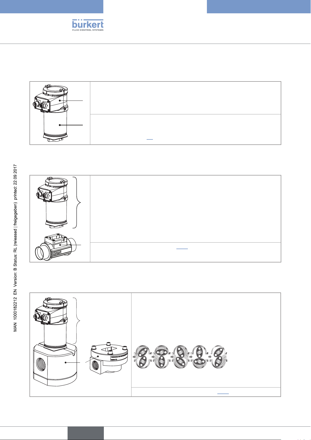
5.2.4 Construction of the SE36 with sensor-fitting S070 or S077
The flow transmitter SE36 with sensor-fitting S070 or S077 comprises:
A: an S070 or S077 sensor-fitting including the flow sensor with
oval gears.
Set in rotation by the flow, the magnets integrated in the oval
B
gears generate pulses, the frequency of which is proportional to
the volume of fluid. A conversion coefficient specific to each pipe
(material and diameter) is necessary to establish the flow rate
value associated with the measurement.
12
A
S070
The conversion coefficient (K-factor) expressed in pulses per litre
is given in the user manual for the sensor-fitting used.
B: a flow transmitter SE36 (see chap. 5.2.2)
English
Page 13
8026 Flow-Meter V2
1
8
10
11
SE36/8036 Flow-Meter With Display V2
Supply: 14-36V
Output: 1x4-20mA 1xTransistor 700 mA Max NPN
Cell: HALL INLINE
Process: Temp -15/110°C
PN 16 Bar
IP65-IP67 W4YME
S-N:2608
00561880
Made in France
1
2
3
4
5
6
7
8
9
1:V+
2:NPN1
3:0V
Type 8026 - 8036 - SE36
Description
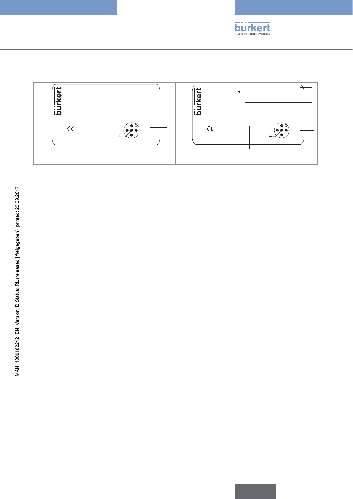
5.3 Description of the name plate
Supply: 14-36VDC
Output: 1x4-20mA 2xTransistors 500 mA Max
Cell: HALL INSERTION SHORT
Process: Temp -15/100°C
PN 10 Bar
Made in France
IP65-IP67 W41MT
9
S-N:2024
00560861
2:NPN/PNP1
3:0V
4:NPN/PNP2
1:V+
Flowmeter 8026 Flowmeter 8036 or flow transmitter SE36
Fig. 1 : Examples of a name plate
1. Type of the device, measured variable and version
2. Power supply
3. Output specifications
4. Type of sensor
5. Fluid temperature range
6. Fluid pressure
7. Allocation of the pins on the M12 fixed connectors
2
3
4
5
6
7
8. Manufacturing code
9. Order code
10. Serial number
11. Protection rating
13
English
Page 14
Type 8026 - 8036 - SE36
Description
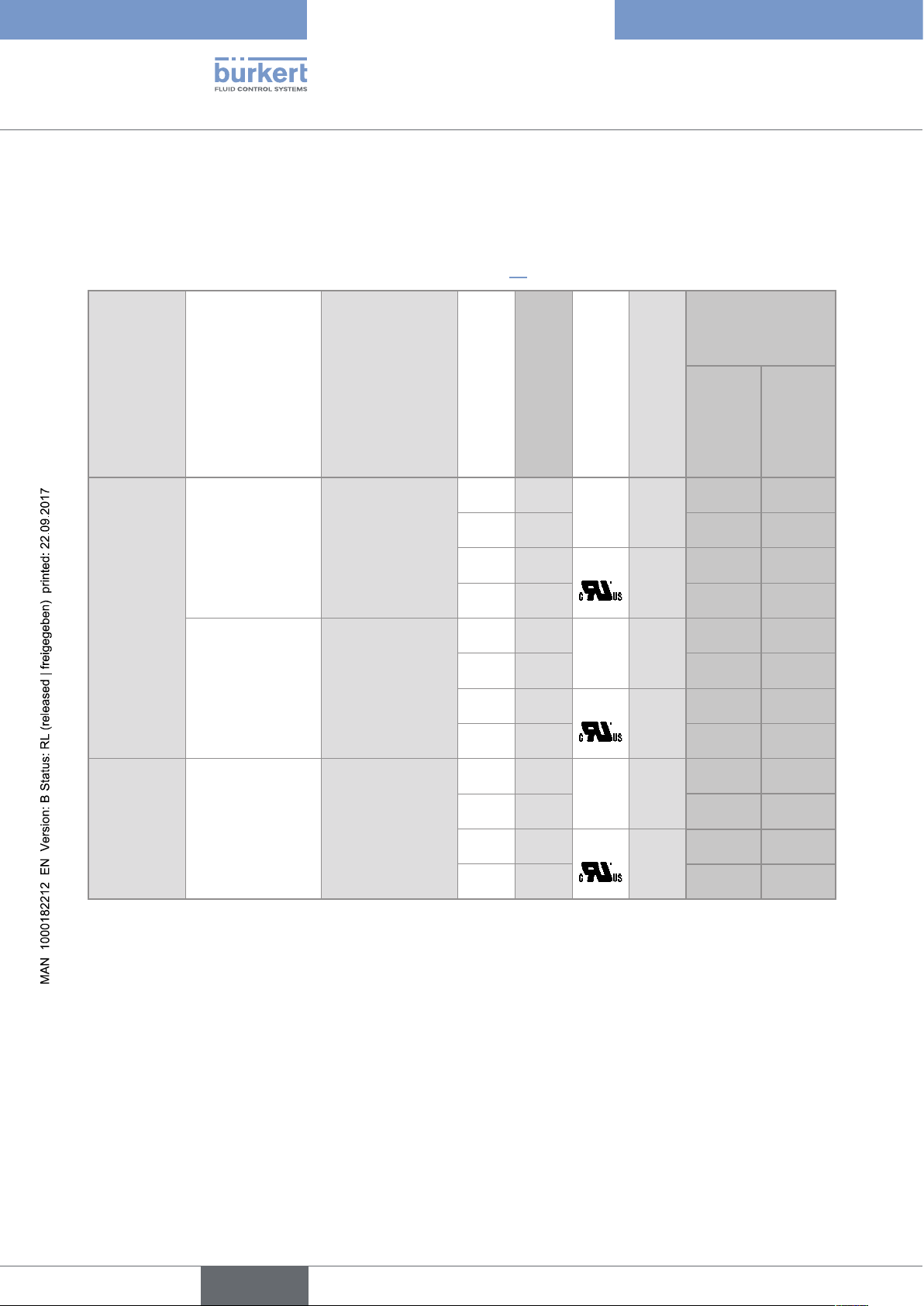
5.4 Available versions of type 8026
The following versions of the 8026 flowmeter are available. Each version of the 8026 flowmeter is available
without or with the display module.
The display module is also available as an accessory (see chap. 11).
Order code of the
8026
Voltage supply
14-36 V DC 1 NPN transistor +
1 x 4-20 mA
2 x transistor,
NPN/PNP, + 1 x
4-20 mA
12-36 V DC 2 x transistor,
NPN/PNP, + 2 x
4-20 mA
1)
A set with additional seals (1 green FKM seal + 1 black EPDM seal) is delivered with each device.
Outputs
Electrical connection
Male 5-pin M12
fixed connector
Male 5-pin M12
fixed connector
Male 5-pin M12
fixed connector +
female 5-pin M12
fixed connector
Type of sensor
Seal of the sensor
UL
Type of connection of
Short FKM 1)no 2-wire
Long FKM
Short FKM
Long FKM
Short FKM
Long FKM
Short FKM
Long FKM
Short FKM
Long FKM
Short FKM
Long FKM
1)
1)
yes 2-wire
1)
1)
no 2-wire
1)
1)
yes 2-wire
1)
1)
no 3-wire
1)
1)
yes 3-wire
1)
the outputs
without
560 860 561 860
560 870 561 870
560 863 561 863
560 873 561 873
560 861 561 861
560 871 561 871
560 864 561 864
560 874 561 874
560 862 561 862
560 872 561 872
560 865 561 865
560 875 561 875
display
module
with display
module
14
English
Page 15
Type 8026 - 8036 - SE36
Description
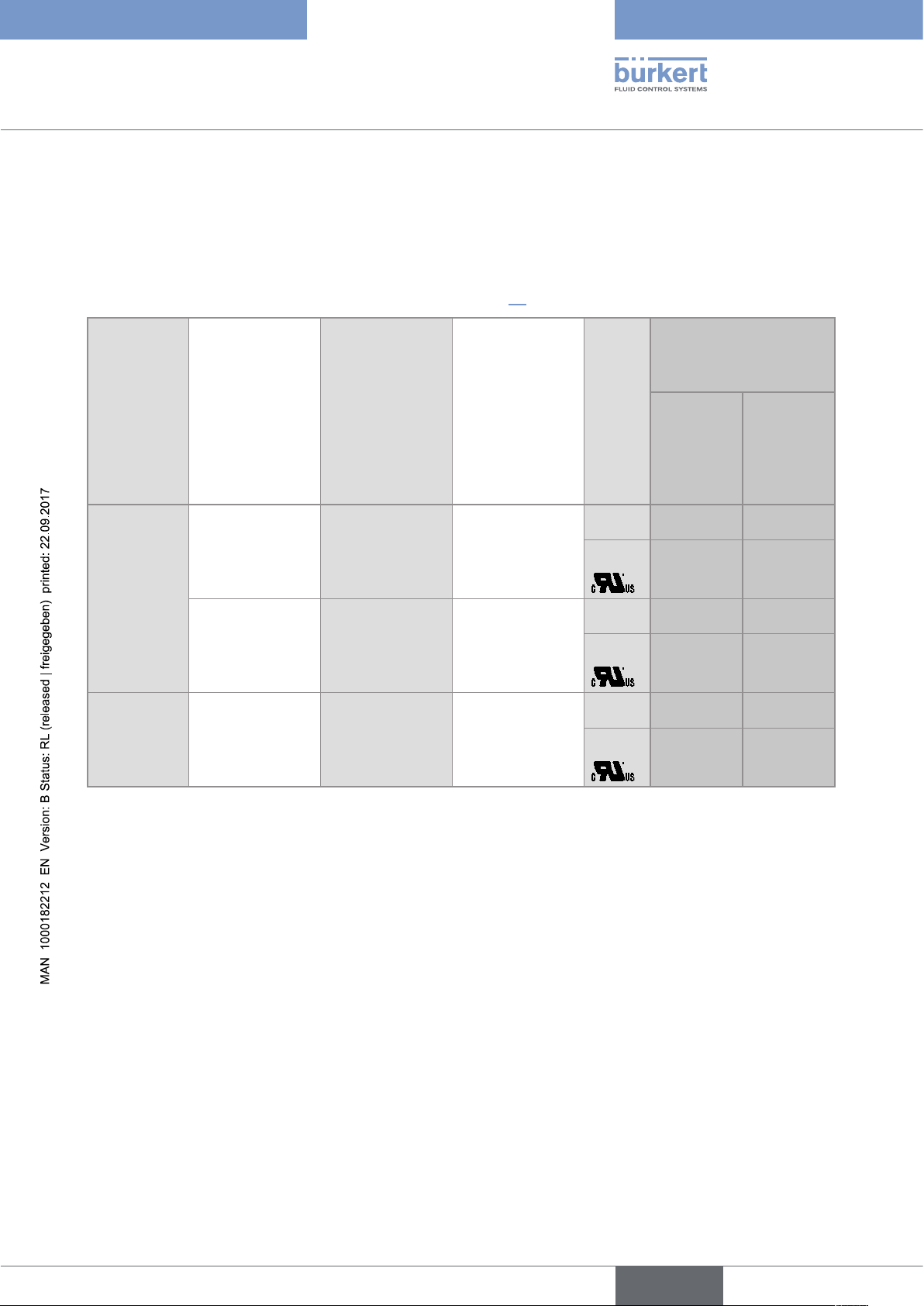
5.5 Available versions of the transmitter SE36
The following versions of the transmitter SE36 are available. The references of the S030 and S077 sensor-fittings
including the flow sensor can be found on the related technical data sheets for these product types.
Each version of the transmitter is available without or with the display module.
The display module is also available as an accessory (see chap. 11).
Order code of the SE36
Voltage supply
14-36 V DC 1 NPN transistor
+ 1 x 4-20 mA
2 x transistor,
NPN/PNP, + 1 x
4-20 mA
12-36 V DC 2 x transistor,
NPN/PNP, + 2 x
4-20 mA
Outputs
Electrical connection
Male 5-pin M12
fixed connector
Male 5-pin M12
fixed connector
Male 5-pin M12
fixed connector +
female 5-pin M12
fixed connector
Type of connection of the
outputs
2-wire no
yes
2-wire no
yes
3-wire no
yes
without
display
UL
560 880 561 880
560 883 561 883
560 881 561 881
560 884 561 884
560 882 561 882
560 885 561 885
module
with display
module
English
15
Page 16
Type 8026 - 8036 - SE36
Technical data
6 TECHNICAL DATA
6.1 Conditions of use
Ambient temperature -10 to +60 °C
Air humidity < 85%, non condensated
Protection rating according to
EN 60529
6.2 Conformity to standards and directives
6.2.1 Conformities common to the 8026 and the SE36
IP67 and IP65 with connectors plugged in and tightened and transmitter
cover fully closed and sealed
• EMC: EN 61000-6-2, EN 61000-6-3
• Vibration: EN 60068-2-6
• Shock: EN 60068-2-27
For UL devices (
• UL 61010-1
• CAN/CSA-C22.2 n° 61010-1
) in the United States of America and Canada:
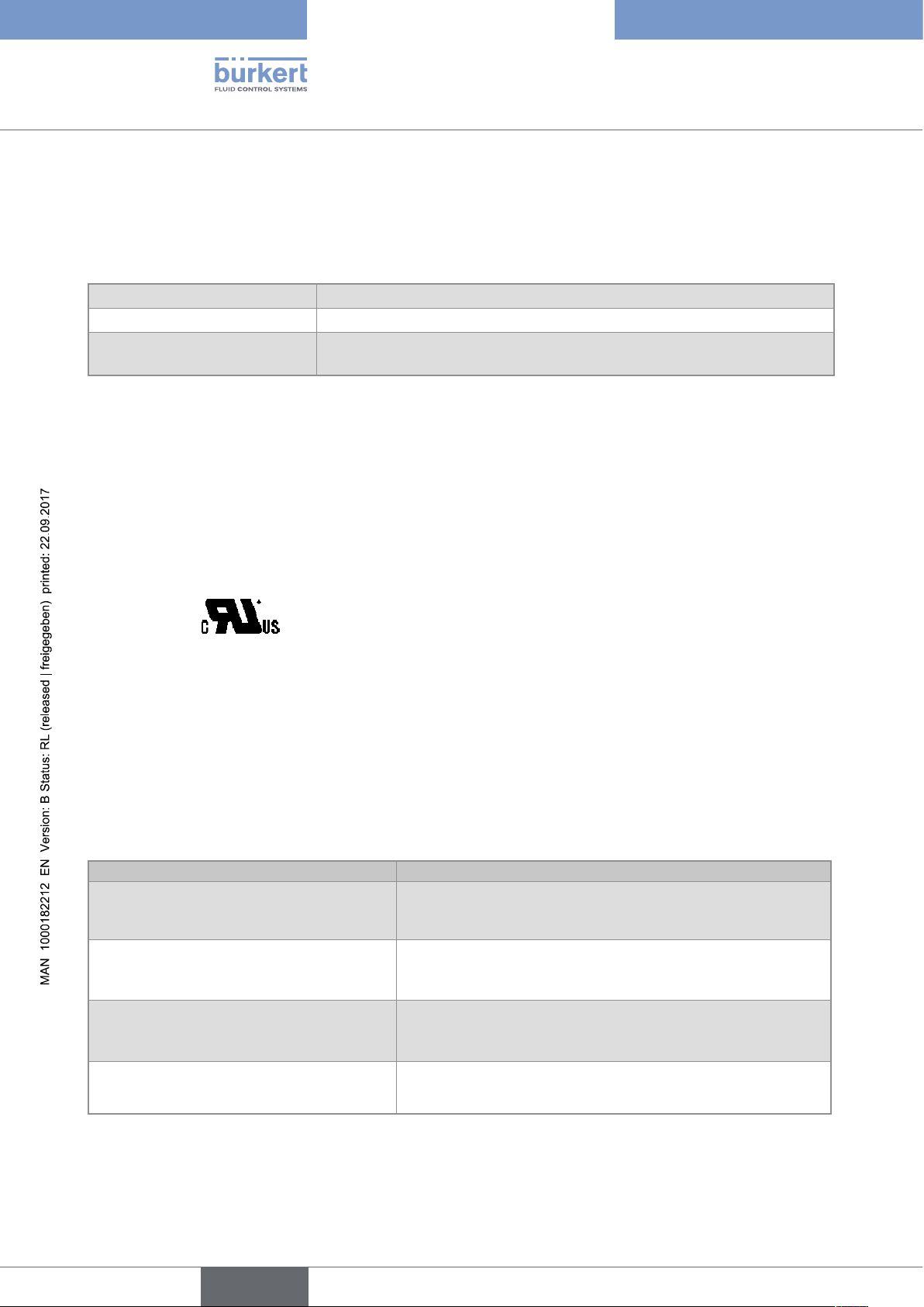
6.2.2 Conformity to the pressure equipment directive
The devices 8026 and the sensor-fittings S030, S070 and S077 comply with article 3§3 of the pressure
equipment directive 97/23/CE.
According to this directive, the product can only be used in the following cases (depending on max. pressure,
pipe diameter and fluid):
Type of fluid Conditions
Fluid group 1, par. 1.3.a • Flowmeter 8026 and sensor-fitting S030: DN ≤ 25 only
• Sensor-fittings S070 and S077: Forbidden
Fluid group 2 par. 1.3.a DN ≤ 32
16
or DN > 32 and PNxDN ≤ 1000
Fluid group 1 par. 1.3.b • Flowmeter 8026: DN ≤ 25 or DN > 25 and PNxDN ≤ 2000
• Sensor-fittings S030, S070 and S077: PNxDN ≤ 2000
Fluid group 2 par. 1.3.b • Flowmeter 8026: DN ≤ 400
• Sensor-fittings S030, S070 and S077: DN ≤ 200
English
Page 17
Type 8026 - 8036 - SE36
Technical data
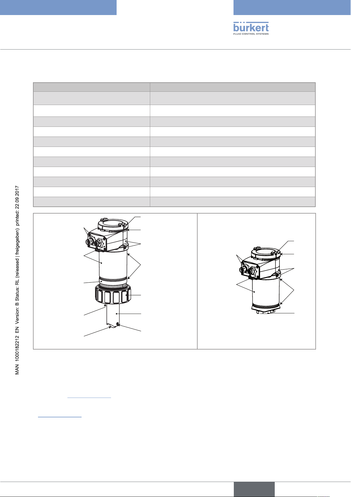
6.3 Mechanical data
Part Material
Box / seals stainless steel 1.4404, PPS / EPDM
Cover / seal PC / silicone
Display module PC / PBT
M12 fixed connector nickel-plated brass (stainless steel on request)
Fixed connector holder stainless steel 1.4404 (316L)
Screws stainless steel
Nut PC
Flow sensor holder / seal (only 8026) PVDF / FKM (default)
Axis and shaft of the paddle wheel (only 8026) Ceramic (Al
Paddle wheel (only 8026) PVDF
2O3
)
Quarter-turn system (only SE36) PC
PC
nickel-plated
brass
silicone
(stainless steel)
PPS
nickel-plated
stainless steel
EPDM
PPS
(stainless steel)
stainless steel
PC
FKM
PVDF
PVDF
ceramic (Al
2O3
)
Flowmeter 8026 Transmitter SE36
Fig. 2 : Materials used in the flowmeter 8026 and the transmitter SE36
brass
PC
silicone
PPS
EPDM
PC
• Materials in contact with the fluid (only for 8026): PVDF, ceramic, FKM (default).
• Dimensions of devices: please refer to the technical data sheets regarding the types 8026, 8036 or SE36
avalaible at www.burkert.com
• Mechanical data of fittings: please refer to the technical data sheets regarding the related fittings, avalaible at
www.burkert.com
English
17
Page 18
6.4 Fluid data
Type 8026 - 8036 - SE36
Technical data
Pipe diameter
DN06 to DN400;
For fitting S020 or sensor-fitting S030, the appropriate diameter
is determined using the flow rate / DN / fluid velocity graphs:
refer to the manuals of the fittings
Fluid temperature
• 8026
• -15 to +100 °C; Also factor in the fluid temperature/pressure
dependency for the 8026 with fitting S020 : see Fig. 3
• 8036 • see the manual delivered with the sensor-fitting S030 or the
technical data sheet
• SE36 with a sensor-fitting S070 or S077 • see the manual delivered with the sensor-fitting S070 or S077
or the technical data sheet
Fluid pressure
Also refer to the requirements of the Pressure Equipment
Directive: see chap. 6.2.2
• 8026
• PN10; Also factor in the fluid temperature/pressure
dependency for the 8026 with fitting S020 (see Fig. 3)
• 8036 • see the manual delivered with the sensor-fitting S030 or the
technical data sheet
• SE36 with a sensor-fitting S070 or S077 • see the manual delivered with the sensor-fitting S070 or S077
or the technical data sheet
Type of fluid
• 8026 and 8036 • Neutral or slightly aggressive fluids
• SE36 with sensor-fitting S070 or S077 • Viscous fluids, free of solid particles
Fluid viscosity
• 8026 and 8036 • 300 cSt max.
• SE36 with sensor-fitting S070 or S077 • see the manual delivered with the sensor-fitting S070 or S077
or the technical data sheet
Solid particle rate in the fluid
• 8026 and 8036 • ≤ 1%
• SE36 with sensor-fitting S070 or S077 • 0 %
Flow rate measurement
• Measurement range • 0,3 to 10 m/s
1)
• Linearity • ±0,5%
• Repeatability • ±0,4%
• Measurement deviation with standard K-factor • ±2,5%
• Measurement deviation with a Teach-In
• ±1%
of the full scale
1)
of the measured value
1)
of the measured value
1)
of the measured value (at the Teach-In point)
procedure
1)
Determined in the following reference conditions: fluid = water, water and ambient temperatures = 20 °C, upstream and
downstream distances respected, appropriate pipe dimensions.
18
English
Page 19
Type 8026 - 8036 - SE36
Technical data
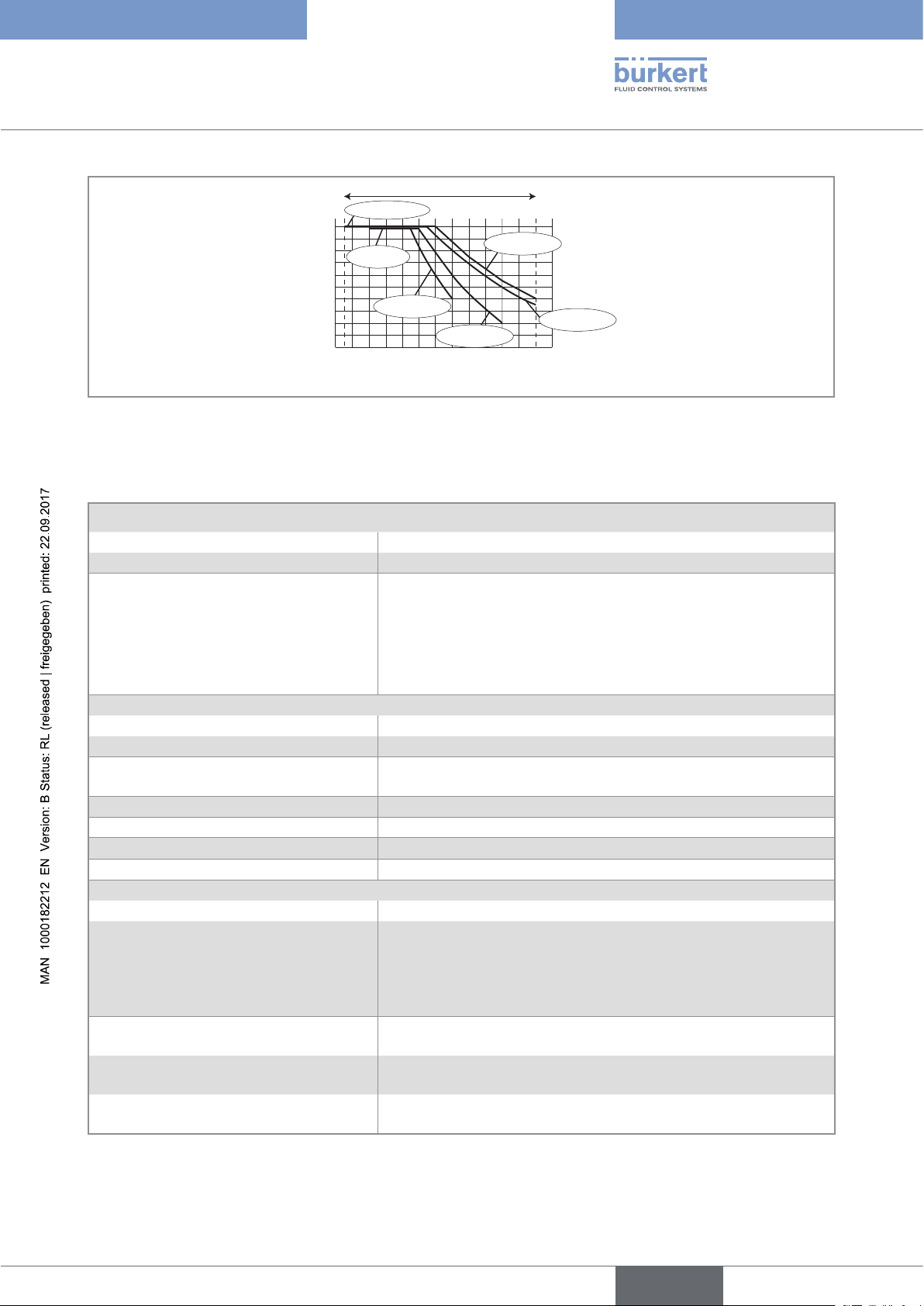
A
P (bar)
10
9
8
7
6
5
4
3
2
1
0
-10 +10 +30 +50 +70 +90 +110
PVDF +
PVC + PP
Metal
PVC (PN10)
PP (PN10)
Metal
(PN10)
PVDF (PN10)
T (°C)
A: Operating range
Fig. 3 : Fluid temperature-pressure dependency for the flowmeter 8026 associated to a fitting S020
6.5 Electrical data
Power supply
• version with 2 or 3 outputs (2 wires) • 14-36 V DC, filtered and regulated
• version with 4 outputs (3 wires) • 12-36 V DC, filtered and regulated
Specifications of the power source
(not supplied) of the UL devices
• limited energy source (in accordance to UL 61010-1,
paragraph 9.3)
or
• Class 2 source (in accordance to standards 1310/1585 and
60950-1)
Current consumption
• version with 2 or 3 outputs (2 wires) • 25 mA max. (at 14 V DC)
• version with 4 outputs (3 wires) • 5 mA max. (at 12 V DC)
Current consumption, with loads on
1 A max.
the transistors
Power consumption
Protection against polarity reversal
Protection against voltage spikes
Protection against short circuits
40 W max.
yes
yes
yes, transistor outputs
Transistor output
• Version with only 1 transistor output • NPN, open collector, 700 mA max., 1-36 V DC
• Version with 2 transistor outputs • NPN (/sink) or PNP (/source) (depending on parameter setting),
open collector, 700 mA max., 500 mA max. per transistor if both
transistor outputs are wired.
NPN output: 1-36 V DC
PNP output: supply voltage
Current output
4-20 mA, sink ("NPN sink") or source ("PNP source") (depending
on parameter setting)
• Version with only 1 current output (2
wires)
• max. loop impedance: 1100 W at 36 V DC, 610 W at 24 V DC,
180 W at 14 V DC
• version with 2 current outputs (3 wires) • max. loop impedance: 1100 W at 36 V DC, 610 W at 24 V DC,
100 W at 12 V DC
English
19
Page 20
Type 8026 - 8036 - SE36
Assembly
7 ASSEMBLY
7.1 Safety instructions
DANGER
Risk of injury due to electrical voltage.
▶ Shut down and isolate the electrical power source before carrying out work on the system.
▶ Observe all applicable accident protection and safety regulations for electrical equipment.
WARNING
Risk of injury due to non-conforming assembly.
▶ The device must only be assembled by qualified and skilled staff with the appropriate tools.
Risk of injury due to unintentional switch on of power supply or uncontrolled restarting of the
installation.
▶ Take appropriate measures to avoid unintentional activation of the installation.
▶ Guarantee a defined or controlled restarting of the process after any intervention on the device.
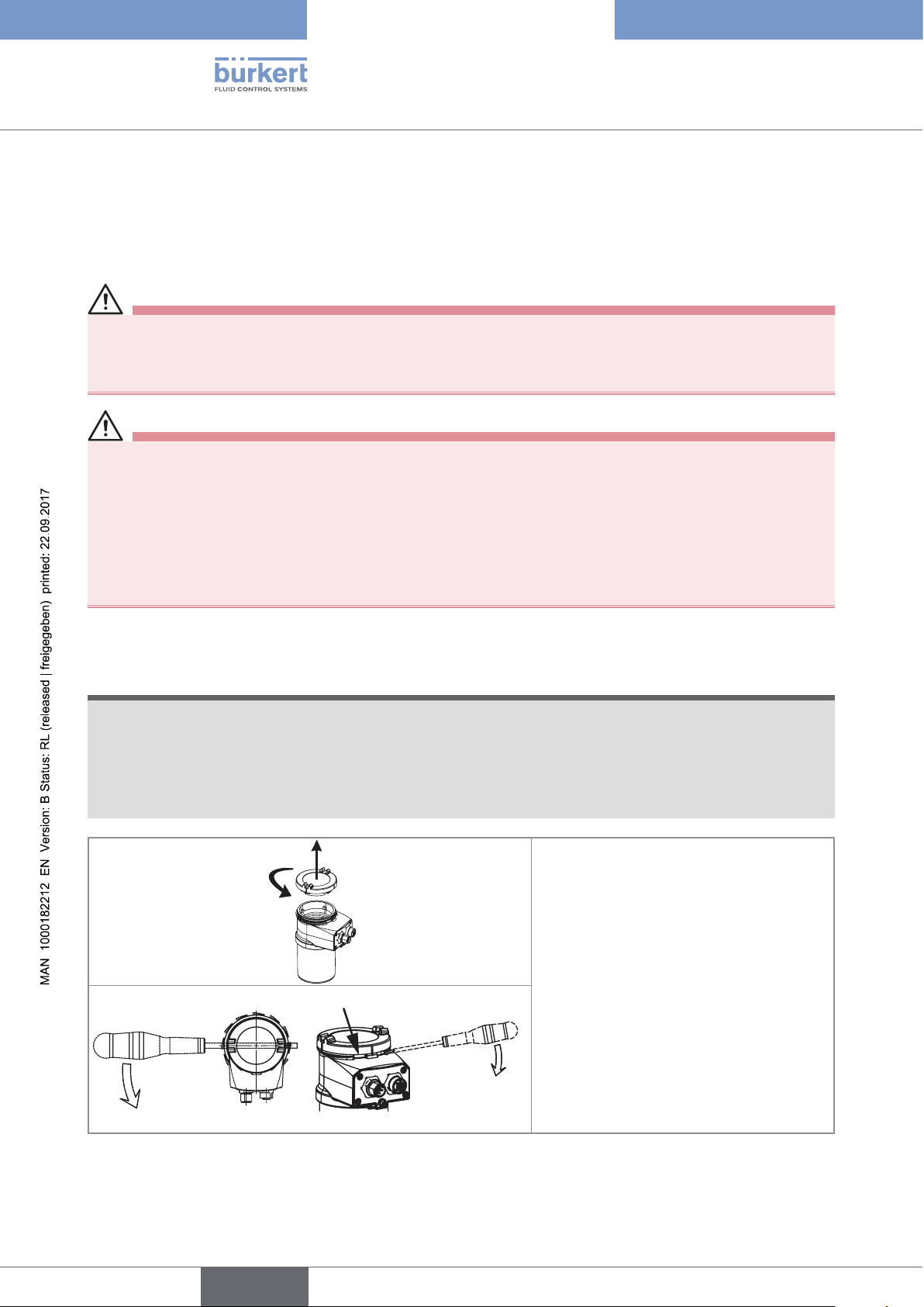
7.2 Removing the cover
NOTE
The tightness of the device is not guaranteed when the cover is removed.
▶ Once the cover is removed, prevent ingress of liquid inside the housing.
The device may be damaged if a metal component comes into contact with the electronics.
▶ Prevent contact of the electronics with a metal component.
2
1
→ [1] Turn the cover counterclockwise with
an angle of about 15° to unlock it.
→ [2] Remove the cover.
If the cover grips to the housing:
20
→ Use an appropriate tool to unlock the
cover, taking care not to scratch the glass.
→ Insert an apropriate tool into the groove of
the housing.
→ Lever the cover up.
Fig. 4 : Removing the cover
English
Page 21
1
Type 8026 - 8036 - SE36
Assembly
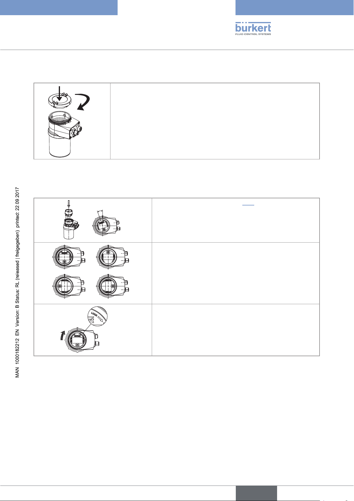
7.3 Mounting the cover
→ Check that there is a seal on the housing and that it is not damaged. Replace
it if necessary.
2
→ Grease the seal if necessary, using a component compatible with the seal
material.
→ [1] Set the cover to ensure that the 4 grooves of the cover match with the 4
pins of the housing.
→ [2] Turn the cover clockwise with an angle of about 15° to lock it.
Fig. 5 : Closing the cover
7.4 Mounting the display module
20°
a)
b)
Fig. 6 : Mounting the display module
c)
d)
→ Remove the cover (see chapter 7.2).
→ Set the display module at an angle of about 20° in relation to
the desired position.
→ The module can be mounted in 4 different positions, at 90°
intervals.
→ Fully push in the module and turn clockwise to lock it.
21
English
Page 22
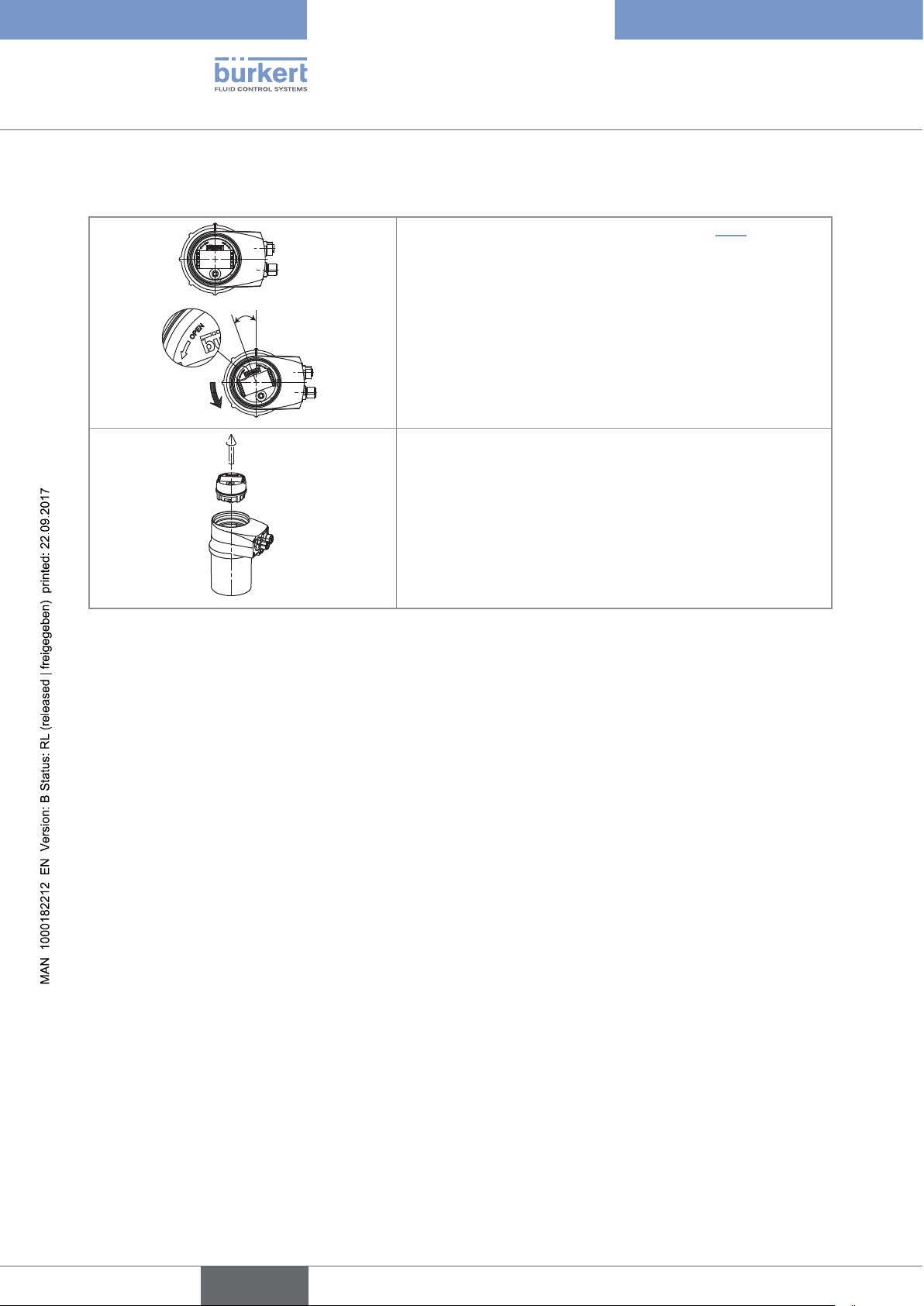
7.5 Removing the display module
→ Remove the cover if necessary (see chapter 7.2).
→ Turn the module by ca. 20° counterclockwise.
Type 8026 - 8036 - SE36
Assembly
20°
Fig. 7 : Removing the display module
Once unlocked, the module is raised slightly by the spring
action.
→ Remove the module from its housing.
22
English
Page 23
Type 8026 - 8036 - SE36
Installation and wiring
8 INSTALLATION AND WIRING
8.1 Safety instructions
DANGER
Risk of injury due to high pressure in the installation.
▶ Stop the circulation of fluid, cut off the pressure and drain the pipe before loosening the process connections.
Risk of injury due to electrical voltage.
▶ Disconnect the electrical power for all the conductors and isolate it before carrying out work on the system.
▶ Observe all applicable accident protection and safety regulations for electrical equipment.
Risk of injury due to the nature of the fluid.
▶ Respect the prevailing regulations on accident prevention and safety relating to the use of aggressive fluids.
WARNING
Risk of injury due to non-conforming installation.
▶ The electrical and fluid installation can only be carried out by qualified and skilled staff with the appropriate
tools.
▶ Install appropriate safety devices (correctly rated fuse and/or circuit-breaker).
▶ Respect the assembly instructions for the fitting used.
Risk of injury due to unintentional switch on of power supply or uncontrolled restarting of the
installation.
▶ Take appropriate measures to avoid unintentional activation of the installation.
▶ Guarantee a defined or controlled restarting of the process after any intervention on the device.
English
23
Page 24

Type 8026 - 8036 - SE36
Installation and wiring
8.2 Installation of a 8026 on a pipe
DANGER
Risk of injury due to high pressure in the installation.
▶ Stop the circulation of fluid, cut off the pressure and drain the pipe before loosening the process connections.
Risk of injury due to the nature of the fluid.
▶ Respect the prevailing regulations on accident prevention and safety relating to the use of aggressive fluids.
Follow the next steps to install the flowmeter 8026 properly:
1. Install the fitting S020 in the pipe,
2. Insert the flowmeter 8026 into the fitting S020,
3. Complete the installation of the 8026.
8.2.1 Install the fitting S020 in the pipe
Select a fitting S020 adapted to the fluid velocity.
→
To select a fitting, please refer to the chart in the technical data sheet of the related fitting.
Choose a place for the fitting on the pipe so that:
- air bubbles do not appear in the pipe, in the section around the sensor (Fig. 8).
- the pipe is always filled in the section around the sensor (Fig. 8).
Correct
Correct
flow direction
Incorrect
Incorrect
Correct
Incorrect
24
Fig. 8 : Air bubbles within the pipe / Filling of the pipe
ATTENTION
Risk of damage when installing the fitting.
▶ Respect the installation instructions given in the user manual for the fitting.
English
Page 25

Type 8026 - 8036 - SE36
Installation and wiring
→ Install the fitting S020 in the pipe so that the paddle wheel axis of the device is horizontal (Fig. 9).
Fig. 9 : The paddle wheel axis must be horizontal
8.2.2 Install the flowmeter 8026 into the fitting S020
→ Fit the display module to parameter the device (see chap. 7.4).
→ Check that there is a seal on the fitting and that it is not damaged.
Replace the seal if necessary.
→ Place nut A on the fitting and insert circlip B into the groove.
→ Carefully insert the device into the fitting.
If assembly is correct, the device can no longer rotate on itself.
B
A
Fig. 10 : Installation of flowmeter 8026 into the fitting S020
→ Secure the unit with nut A, tightening only by hand.
8.2.3 Complete the installation of the 8026
Wire the device (see chap. 8.5) and supply power to the device.
→
→ Set the K-factor or determine it through a Teach-In procedure (see chap. 9.13.5).
English
25
Page 26

Type 8026 - 8036 - SE36
Installation and wiring
8.3 Installation of a 8036 on a pipe
DANGER
Risk of injury due to high pressure in the installation.
▶ Stop the circulation of fluid, cut off the pressure and drain the pipe before loosening the process connections.
Risk of injury due to the nature of the fluid.
▶ Respect the prevailing regulations on accident prevention and safety relating to the use of aggressive fluids.
Follow the next steps to install the flowmeter 8036 properly:
1. Install the sensor-fitting S030 in the pipe,
2. Assemble the flow transmitter SE36 on the sensor-fitting S030,
3. Complete the installation of the 8036.
8.3.1 Install the sensor-fitting S030 in the pipe
Select a sensor-fitting S030 adapted with the fluid velocity.
→
To select a fitting, please refer to the chart in the technical data sheet of the related fitting.
Choose a place for the sensor-fitting S030 on the pipe so that:
- air bubbles do not appear in the pipe, in the section around the sensor (Fig. 8, chap. 8.2.1).
- the pipe is always filled in the section around the sensor (Fig. 8, chap. 8.2.1).
ATTENTION
Risk of damage when installing the fitting.
▶ Respect the installation instructions given in the user manual for the fitting.
→ Install the sensor-fitting S030 in the pipe so that the paddle wheel axis is horizontal (Fig. 9, chap. 8.2.1).
8.3.2 Assemble the flow transmitter SE36 on the sensor-fitting
S030
26
→ Fit the display module to parameter the device (see chap. 7.4).
English
Page 27

SE36
2
3
Type 8026 - 8036 - SE36
Installation and wiring
→ 1: Insert the flow transmitter SE36 in the sensor holder.
→ 2: Turn the flow transmitter SE36 by a quarter turn.
1
S030
Fig. 11 : Assembling the flowmeter 8036
→ 3: Secure the flow transmitter SE36 and the sensor-fitting
S030 by tightening the screw to a max. torque of 1 Nm.
8.3.3 Complete the installation of the 8036
Wire the device (see chap. 8.5) and supply power to the device.
→
→ Set the K-factor or determine it through a Teach-In procedure (see chap. 9.13.5).
8.4 Installation of a flow transmitter SE36 with sensorfitting S070 or S077 in a pipe
DANGER
Risk of injury due to high pressure in the installation.
▶ Stop the circulation of fluid, cut off the pressure and drain the pipe before loosening the process connections.
Risk of injury due to the nature of the fluid.
▶ Respect the prevailing regulations on accident prevention and safety relating to the use of aggressive fluids.
Follow the next steps to install the flow transmitter SE36 properly on the sensor-fitting S070 or S077, mounted in
the pipe:
1. Install the sensor-fitting S070 or S077 in the pipe,
2. Assemble the flow transmitter SE36 on the sensor-fitting S070 or S077,
3. Complete the installation of the flow transmitter SE36 with sensor-fitting S070 or S077.
8.4.1 Install the sensor-fitting S070 or S077 in a pipe
Select a sensor-fitting S070 or S077 adapted to the fluid viscosity.
→
To select a fitting, please refer to the chart in the technical data sheet of the related fitting.
27
English
Page 28

S077
Type 8026 - 8036 - SE36
Installation and wiring
→ Install the sensor-fitting S070 or S077 in the pipe so that the oval gear axes are in the horizontal plane
(see Fig. 12).
Correct Incorrect
Fig. 12 : The oval gear axes must be horizontal
8.4.2 Assemble the flow transmitter SE36 on the sensor-fitting
S070 or S077
→ Fit the display module to parameter the device (see chap. 7.4).
→ 1: Insert the flow transmitter SE36 in the sensor holder.
→ 2: Turn the flow transmitter SE36 by a quarter turn.
1
2
Fig. 13 : Assembling the flow transmitter SE36 with sensor-fitting S070 or S077
SE36
→ 3: Secure the flow transmitter SE36 and the sensor-fitting S070 or
S077 by tightening the 2 screws to a max. torque of 1 Nm.
3
S070
8.4.3 Complete the installation of the flow transmitter SE36 with
sensor-fitting S070 or S077
Wire the device (see chap. 8.5) and supply power to the device.
→
→ Set the K-factor or determine it through a Teach-In procedure (see chap. 9.13.5).
8.5 Wiring
DANGER
Risk of injury due to electrical voltage.
▶ Shut down and isolate the electrical power source before carrying out work on the system.
▶ Observe all applicable accident protection and safety regulations for electrical equipment.
28
English
Page 29

5,5
Type 8026 - 8036 - SE36
Installation and wiring
• Use a high quality electrical power supply (filtered and regulated).
• Make sure the installation is equipotential (see chap. 8.5.3).
• Use a shielded cable.
• Once the device is wired, set the "HWMode" parameter depending on the wiring carried out, sink/NPN
or source/PNP (see chap. 9.12.8).
8.5.1 Electrical connections
Number of fixed connectors Type of connectors
1 male M12 fixed connector
female 5-pin M12 (available as an accessory: see chap. 11)
1 male M12 fixed connector and 1 female
M12 fixed connector
female 5-pin M12 + male 5-pin M12 (both available as accessories:
see chap. 11)
8.5.2 Assembling the male or female connector (accessories:
see chap. 11)
4 3 2 1
→ Unscrew the nut [1] on the body [4].
→ Insert the cable into the nut [1], the cable clamp [2] and the seal [3], and then into
the body [4].
5
→ Strip 20 mm of the cable.
→ Cut the central wire (earth) so that its length is equal to 11.5 mm.
11,5
5,5
20
→ Expose 5.5 mm of the wires on the stripped cable.
→ Insert each wire into the appropriate pin on the terminal block [5] (see chap. 8.5.4
to chap. 8.5.6).
→ Tighten the terminal block [5] wired to the body [4].
→ Tighten the connector nut [1].
Fig. 14 : Multipin M12 connector (available as an accessory)
8.5.3 Equipotentiality of the installation
To ensure the equipotentiality of the installation (power supply - device - fluid):
→ Connect together the various earth spots in the installation to eliminate the potential differences that may
occur between different earthes.
→ Observe faultless grounding of the shield of the power supply cable (see Fig. 15 and Fig. 16).
→ Special attention has to be paid if the device is installed on plastic pipes because there is no direct earthing
possible. Proper earthing is performed by earthing together the metallic devices such as pumps or valves, that
are as close as possible to the device (see Fig. 16).
29
English
Page 30

Type 8026 - 8036 - SE36
Installation and wiring
Power supply
+
12-36 V DC
Fig. 15 : Equipotentiality skeleton diagram with pipes in metal
+
12-36 V DC
Power supply
Fig. 16 : Equipotentiality skeleton diagram with pipes in plastic
Devices such as valves,
pumps,..
Pipes in plastic
30
English
Page 31

Type 8026 - 8036 - SE36
Installation and wiring
8.5.4 Wiring a version with a single M12 fixed connector and an
NPN transistor output and a current output
NPN transistor output (TR1)
2
0V
3
1
V+ (14-36 V DC)
4
Not connected
Fig. 17 : Pin assignment of the male fixed connector on a version with 1 NPN transistor output and 1 current output
Pin of the female M12 connector available as an accessory (order code 438680) Colour of the wire
1 brown
2 white
3 blue
4 black
5 grey
Load (solenoid
valve for in-
stance)
white
3
blue
2
1
4
brown
+ -
14-36 VDC
grey
Power supply
Fig. 18 : Wiring the NPN transistor output (parameter setting "NPN/sink", cannot be changed), of a version with 1 M12
fixed connector, 1 NPN transistor output and 1 current output
4-20 mA input (external
instrument)
2
3
1
4
+ -
brown
grey
4-20 mA input (external
instrument)
+ -
2
brown
3
blue
1
4
grey
blue
Power supply
Fig. 19 : Possible electrical connections of the current output only, on a version with 1 M12 fixed connector, 1 NPN
transistor output and 1 current output
+ -
14-36 V DC
Power supply
+ -
14-36 V DC
31
English
Page 32

Load
white
blue
Type 8026 - 8036 - SE36
Installation and wiring
2
brown
3
1
4
grey
4-20 mA input (exter-
nal instrument)
Fig. 20 : Wiring the NPN transistor output and the current output in sinking mode (parameter setting "NPN/sink",
cannot be changed), on a version with 1 M12 fixed connector, 1 NPN transistor output and 1 current output
+ -
+ -
14-36 VDC
Power supply
8.5.5 Wiring a version with a single M12 fixed connector and
two transistor outputs and one current output
Transistor output 1 (TR1)
2
3
0V
Transistor output 2 (TR2)
Fig. 21 : Pin assignment of the male fixed connector on a version with 2 transistor outputs and 1 current output
Pin of the female M12 connector available as an accessory (order code 438680) Colour of the wire
1
V+ (14-36 V DC)
4
1 brown
2 white
3 blue
4 black
5 grey
32
English
Page 33

Type 8026 - 8036 - SE36
Installation and wiring
white
Load 1
(solenoid valve for
instance)
2
brown
3
blue
white
1
4
grey
+ -
Power supply
14-36 V DC
Load 1
(solenoid valve for
black
Load 2
(solenoid valve
for instance)
Fig. 22 : NPN wiring of both transistor outputs (parameter setting "NPN/sink"), of a version with 1 M12 fixed connector
instance)
2
brown
1
black
3
4
grey
blue
Load 2
(solenoid valve for
instance)
+ -
14-36 V DC
Power supply
Fig. 23 : PNP wiring of both transistor outputs (parameter setting "PNP/source"), of a version with 1 M12 fixed
connector
4-20 mA input (external
instrument)
2
brown
3
1
grey
4
+ -
4-20 mA input (external
instrument)
+ -
2
brown
3
blue
1
4
grey
blue
Power supply
Fig. 24 : Possible electrical connections of the current output only (whatever the parameter setting, "NPN/sink" or
"PNP/source"), on a version with 1 M12 fixed connector
+ -
14-36 V DC
Load 1
+ -
black
white
3
2
brown
1
grey
4
Power supply
4-20 mA input (external
instrument)
+ -
14-36 V DC
blue
Load 2
+ -
Power supply
14-36 V DC
Fig. 25 : NPN wiring of both transistor outputs and wiring the current output in sinking mode (parameter setting "NPN/
sink"), of a version with 1 M12 fixed connector
English
33
Page 34

Type 8026 - 8036 - SE36
Installation and wiring
Load 1
white
black
blue
2
brown
3
1
4
grey
Load 2
14-36 V DC
Fig. 26 : PNP wiring of both transistor outputs and wiring the current output in sourcing mode (parameter setting "PNP/
source"), of a version with 1 M12 fixed connector
4-20 mA input (external
instrument)
+ -
Power supply
+ -
8.5.6 Wiring a version with two M12 fixed connectors and two
transistor outputs and two current outputs
Transistor output 1 (TR1)
2
V+ (12-36 V DC)
0V
3
1
4
V+ (12-36 V DC)
Transistor output 2 (TR2)
2
1
3
0V
4
Current output 1 (AC1)
Current output 2 (AC2)
Male fixed connector Female fixed connector
Fig. 27 : Pin assignment of the male and female M12 fixed connectors
Connect the power supply for the device to the male fixed connector; the supply is then transferred internally to pins 1 and 3 of the female fixed connector in order to ease wiring of the load to
the female fixed connector.
Pin of the female respectively male M12 cables available as accessories (order
code 438680 respectively 559177)
Colour of the wire
1 brown
2 white
3 blue
4 black
5 grey
Load 1
(solenoid valve for
instance)
white
3
blue
white
2
brown
1
4
grey
2
1
3
4
brown
Load 2
(solenoid valve
for instance)
34
+ -
Power supply
12-36 V DC
Fig. 28 : NPN wiring of both transistor outputs (parameter setting "NPN/sink"), of a version with 2 M12 fixed connectors
English
Page 35

Type 8026 - 8036 - SE36
Installation and wiring
Load 1
(solenoid valve for
instance)
white
3
white
2
brown
1
4
grey
2
1
3
blue
4
Load 2
(solenoid valve for
instance)
blue
+ -
Power supply
12-36 V DC
Fig. 29 : PNP wiring of both transistor outputs (parameter setting "PNP/source"), of a version with 2 M12 fixed connectors
brown
black
nd
4-20 mA input (external
2
instrument)
2
3
1
4
st
4-20 mA input (external
1
instrument)
+ - + -
2
brown
3
1
black
4
grey
blue
Power supply
+ -
12-36 V DC
Fig. 30 : Wiring of both current outputs in sinking mode, on a version with 2 fixed connectors (parameter setting "NPN/
sink")
st
1
4-20 mA input
(external instrument)
+ -+ -
black
3
blue
2
brown
1
4
grey
+ -
2
blue
3
1
4
black
Power supply
nd
4-20 mA input
2
(external instrument)
12-36 V DC
Fig. 31 : Wiring of both current outputs in sourcing mode, on a version with 2 fixed connectors (parameter setting
"PNP/source")
English
35
Page 36

Type 8026 - 8036 - SE36
Installation and wiring
Load 1
blue
white
3
black
2
4
brown
1
brown
1
grey
4
Load 2
white
2
3
black
st
1
4-20 mA input (ex-
ternal instrument)
+ - + -
+ -
12-36 V DC
2nd 4-20 mA input
(external instrument)
Power supply
Fig. 32 : NPN wiring of both transistor outputs and wiring of both current outputs in sinking mode, on a version with 2
fixed connectors (parameter setting "NPN/sink")
Load 1
Load 2
white
white
st
1
4-20 mA input
(external instrument)
3
black
2
brown
1
4
grey
+ -
blue
+ - + -
12-36 V DC
2
blue
3
1
4
black
nd
2
4-20 mA input
(external instrument)
Power supply
Fig. 33 : PNP wiring of both transistor outputs and wiring of both current outputs in sourcing mode, on a version with 2
fixed connectors (parameter setting "PNP/source")
36
English
Page 37

Type 8026 - 8036 - SE36
Adjustment and commissioning
9 ADJUSTMENT AND COMMISSIONING
• The settings can only be done on a device with a display module.
• Do not remove the display module while making the settings on the device.
9.1 Safety instructions
WARNING
Risk of injury due to non-conforming adjustment.
Non-conforming operating could lead to injuries and damage the device and its surroundings.
▶ The operators in charge of adjustment must have read and understood the contents of this manual.
▶ In particular, observe the safety recommendations and intended use.
▶ The device/installation must only be adjusted by suitably trained staff.
WARNING
Danger due to nonconforming commissioning.
Nonconforming commissioning could lead to injuries and damage the device and its surroundings.
▶ Before commissioning, make sure that the staff in charge have read and fully understood the contents of the
manual.
▶ In particular, observe the safety recommendations and intended use.
▶ The device / the installation must only be commissioned by suitably trained staff.
▶ Before commissioning, set the K-factor of the fitting used (see chap. 9.13.5)
Protect this device against electromagnetic interference, ultraviolet rays and, when installed outdoors, the effects of the climatic conditions.
9.2 When switching on the device
When the device is switched on and the display module mounted on the transmitter, the display indicates the
software version of the display. The display then shows the first screen of the Process level:
L
N
E
P
O
O
C
K
See chap. 9.12.4 to 9.12.7 to choose the data to be displayed in
the Process level.
Flow_L
If the message “ERROR - This display does not support this
Element - Contact Bürkert” is displayed, the version of the display
1243
l/h
module is not compatible with the software version of the device.
Contact your local Bürkert sales office.
Fig. 34 : Display indications when powering on the device
37
English
Page 38

Type 8026 - 8036 - SE36
Adjustment and commissioning
9.3 Knowing the operating levels
The device has 2 operating levels:
Process level
This level is used:
• to read the value of the measured flow rate and/or the sensor input frequency
• to read the values of both volume totalizers
• to reset totalizer 2
• to read both the lowest and highest values of the flow rate or the input frequency that has been measured by
the device since the latest reset (this feature is not active by default),
• to reset both the lowest and highest values of the flow rate or the input frequency, if the feature has been
activated
• to read the current values emitted on the 4-20 mA outputs
• to know the status of the device and the status of the sensor thanks to the relevant icons.
Configuration level
This level comprises 5 menus:
Menu title Relevant icon
"Param": see chap. 9.12
This is
when the
device is being parame-
tered............
....................
"Calib": see chap. 9.13
"Diagnostic": see chap. 9.14
"Test": see chap. 9.15
"Info": see chap. 9.16
38
English
Page 39
Type 8026 - 8036 - SE36
Adjustment and commissioning
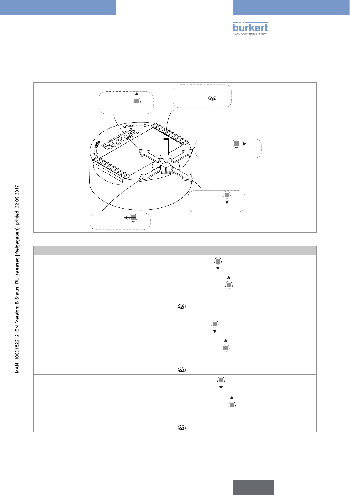
9.4 Using the navigation button
Symbolised by in
Symbolised by
this manual
Symbolised by in
this manual
Fig. 35 : Using the navigation button
You want to... Press...
...browse in Process level
• next screen:
this manual
in
Symbolised by in
this manual
Symbolised by in
this manual
• ...access the Configuration level
• ...display the Param menu
...browse in the menus of the Configuration level
...access the menu displayed
...browse in the menu functions
...select the highlighted function
• previous screen:
for at least 2 sec., from any screen of the Read
level
• next menu:
• previous menu:
• next function:
• previous function:
39
English
Page 40

You want to... Press...
...browse in the dynamic functions bar (MEAS, BACK,
ABORT, OK, YES, NO)
...confirm the highlighted dynamic function
...modify a numerical value
- increment the figure selected
- decrement the figure selected
- select the previous figure
- select the next figure
- allocate the "+" or "-" sign to the numerical value
- move the decimal point
next function:
previous function:
-
-
-
-
then
then
place
Type 8026 - 8036 - SE36
Adjustment and commissioning
to the extreme left of the numerical value
until the desired sign is displayed
to the extreme right of the numerical value
until the decimal point is in the desired
9.5 Using the dynamic functions
You want to... Choose...
...go back to the Process level, without validating the modifications made dynamic function "MEAS"
...confirm the entering dynamic function "OK"
...go back to the parent menu dynamic function "BACK"
...abort the current operation and go back to the parent menu dynamic function "ABORT"
...answer the question asked dynamic function "YES" or "NO"
40
English
Page 41

Type 8026 - 8036 - SE36
Adjustment and commissioning
9.6 Entering a numerical value (example)
Modify each digit of the numerical value using:
to increase the digit selected,
-
This is
where the
device is being parame-
tered............
AC1 4mA
....................
+0.000l/h
MEAS ABORT OK
to decrease the digit selected.
-
After confirming the numerical value entering, modify the
time unit using
or
Select the digit at the extreme right of the numerical value
with
then move the decimal point with .
Dynamic functions (accessible through and ): see chap. 9.5
9.7 Browsing in a menu (example)
Title of the current menu, sub-menu or
The icon identifies the
current menu
This is
when the
device is being parame-
tered............
Param
....................
Line1
Highlighted
function
Line2
Contrast
MEAS ABORT OK
Dynamic functions (accessible through and ): see chap. 9.5
function.
The arrow indicates that some more
functions are available which can be
displayed by using
The arrow indicates that some more
functions are available which can be
displayed by using
English
41
Page 42

HOLD
T
Type 8026 - 8036 - SE36
Adjustment and commissioning
9.8 Knowing the icons and LEDs
• The display module is not available on all versions of the device. The display module is can be ordered
as an accessory (see chap. 11).
L
O
N
C
E
P
O
Red LED:
shows an error;
see chap. 10.3
Yellow LED: shows that transis-
tor 1 is switched
N
E
P
O
Flow_L
K
Flow_m3
L
O
C
K
600.0l/h
0.60/h
not used
Yellow LED: shows that transistor 2
is switched
Yellow LED: shows that
transistor 1 is switched
Yellow LED: shows that
transistor 2 is switched
Green LED: shows that
the device is energized
Red LED: shows an error;
see chap. 10.3
Fig. 36 : Position of the icons and description of the LEDs
• The LEDs of the display module are duplicated on the electronic board that is located under the display
module: these LEDs become visible when the device is not equipped with the display module.
• The yellow LED related to a transistor output is deactivated if the transistor output is configured in pulse
mode ("Pulse").
Icon Possible cause and alternatives
Sensor input frequency within the defined ranges
42
ERR
The alternatives, in this position, if monitoring of the sensor input frequency is activated, are:
•
, associated with : see chap. 9.14.2 and chap. 10.3
, associated with
•
ERR
: see chap. 9.14.2 and chap. 10.3
The device is measuring.
The alternative icons in this position are:
!
•
flashing: HOLD mode activated (see chap. 9.13.1)
•
: running check that the outputs are working and behaving correctly (see chap. 9.15.2 and 9.15.3)
"warning" message ; see chap. 9.14.2 and chap. 10.3
"error" message ; see chap. 9.14.2 and chap. 10.3
English
Page 43

Type 8026 - 8036 - SE36
Adjustment and commissioning
9.9 Knowing the Process level
A
l/h
/h
1) 2)
1)
1) 2)
Display of the minimum and maximum
input flows or fre-
quencies measured.
Display of the cur-
Zoom on the value
of the first current
First view of the Pro-
cess level.
Zoom on the value
in the first line.
Zoom on the value in
the second line.
Flow_L
1243l/h
Flow_m3
1. 243/h
Flow_L
1243
Flow_m3
1.243
B
rent outputs.
output.
Max
1250l/h
Min
1200l/h
AC1
18.3 mA
AC2
7.5 mA
AC1
18.3 mA
3)
Reset Yes/No
Display of the main
Tot1_L
volume totalizer.
987654
Zoom on the value
AC2
of the second cur-
Display of the sec-
ond volume total-
izer.
Tot2_m
3
987
rent output.
Reset Yes/No
7.5 mA
A
B
1)
These displays appear if line 1 and line 2 are activated. Only line 1 is activated by default. To activate/deactivate these
displays or choose the parameters to be displayed, see chap. 9.12.4.
2)
Only the time unit is displayed when the PVAR chosen is "Flow_m3", "Flow_gal" or "Flow_Igal".
3)
Display of the minimum and maximum flow rates in the Process level is deactivated by default. To activate it, see
chap. 9.12.6
English
43
Page 44

9.10 Accessing the Configuration level
Type 8026 - 8036 - SE36
Adjustment and commissioning
Any view of the Process
level
> 2s
This is
when the
device is being parame-
tered............
....................
Parameters Menu
This is
when the
device is being parame-
tered............
....................
Calibration Menu
This is
when the
device is being parame-
tered............
....................
Diagnostic Menu
Test Menu
This is
when the
device is being parame-
tered............
....................
Param
Calib
Diagnostic
Test
Wrong
code
Code
"Param"
1)
OK
Code
"Calib"
1)
OK
Code
"Diagnostic"
1)
OK
Code
"Test" OK
1)
This is
when the
device is being parame-
tered............
Param
....................
System
Display
Outputs
MEAS BACK
Calibration
System
Outputs
Sensor
MEAS BACK
Diagnostic
System
Sensor
MEAS BACK
Test
System
Outputs
Sensor
MEAS BACK
44
Info
Error
Info
Information Menu
1)
Only if the access code to the menu has been customized. See chap. 9.12.2, 9.13.2, 9.14.1 and 9.15.1.
Warning
Smiley
MEAS BACK
Info
Warning
Smiley
Software
MEAS BACK
→ See chap. 9.11 for the detailled functions.
English
Page 45

Type 8026 - 8036 - SE36
Adjustment and commissioning
9.11 Knowing the structure of the Configuration menus
See chap. 9.10 to access the Configuration level.
This is
Param
when the
device is being parame-
tered............
....................
System
This is
when the
device is being parame-
tered............
....................
Up/Download
Download
Downl. Yes/No
If an "upload" has been
made with this module
Upload
Upload Yes/No
Display
Code
Factory Set
This is
when the
device is being parame-
tered............
....................
Line1 / Line2:
0***
Execute
Line 1/Line2:
Confirm 0***
Reset Yes/No
Enabled
Disabled
PVar:
Flow_L
Flow_m3
Flow_gal
Flow_Igal
Freq.
Unit:
/h
/min
If PVar ≠ Freq.
/s
Filter:
Hz
Slow
If PVar = Freq.
Fast
None
Totalizers Total1 / Total 2
Unit
Liter
m3
gal
Igal
Min/Max
Contrast
Backlight
Status
PVar
Unit: /h
xx%
xx%
Enabled
Disabled
Flow_L
Flow_m3
Flow_gal
Flow_Igal
Freq.
/min
/s
Hz
If PVar ≠ Freq.
If PVar = Freq.
45
English
Page 46

Type 8026 - 8036 - SE36
Adjustment and commissioning
Param
This is
when the
device is being parame-
tered............
....................
Outputs
This is
when the
device is being parame-
tered............
....................
HWMode
AC1 / AC2 PVar:
sink/NPN
source/PNP
On a version with 2 transistor outputs
Flow_L
Flow_m3
Flow_gal
Flow_Igal
Freq.
Tot1_L
Tot1_m3
Tot1_gal
Tot1_Igal
Tot2_L
Tot2_m3
Tot2_gal
Tot2_Igal
4mA: ENTER
20mA: ENTER
Filter:
Slow
Fast
None
Mode diag.:
None
22mA
TR1 / TR2 PVar:
Flow_L
Flow_m3
Flow_gal
Flow_Igal
Freq.
Tot1_L
Tot1_m3
Tot1_gal
Tot1_Igal
Tot2_L
Tot2_m3
Tot2_gal
Tot2_Igal
Lit/Pulse
m3/Pulse
Gal/Pulse
Igal/Pulse
Warning
If "Mode" ≠ "Pulse"
If "Mode" = "Pulse"
46
English
Page 47

Type 8026 - 8036 - SE36
Adjustment and commissioning
Param
Calib
This is
when the
device is being parame-
tered............
....................
Outputs
This is
when the
device is being parame-
tered............
....................
TR1 / TR2
Mode: Hysteresis
Window
Pulse
If "PVar" ≠ "Warning"
Low: ENTER
High: ENTER
Contact:
Normally open
If "Mode" ≠ "Pulse"
Normally closed
Delay: ENTER
System
Hold
Pulse: ENTER
Hold: Disable
If "Mode" = "Pulse"
Hold: Enable
0***
Reset Yes/No
Reset Yes/No
4mA:
20mA:
ENTER
Confirm
ENTER
ENTER
0***
Outputs
Sensor
Code
Total 1
Total 2
AC1 / AC2
K.fact.
Vol.Teach
Flow Teach
PVar:
Start Teach
PVar:
Start Teach
Litre
m3
gal
Igal
Meas.Progress
Input Vol.
Cal.Result
Flow_L
Flow_m3
Flow_gal
Flow_Igal
Freq.
Measure
Flow Teach
Cal.Result
English
47
Page 48

Type 8026 - 8036 - SE36
Adjustment and commissioning
Diagnostic
Test
System
Sensor
System
Outputs
Sensor
Code
Frequency
Code
AC1
AC2
TR1
TR2
PVar:
0***
Activate
Frequency
Warn Hi
Warn Lo
Err Hi
Err Lo
0***
AC1 Simul:
AC2 Simul:
TR1 Simul:
TR2 Simul:
Flow_L
Flow_m3
Flow_gal
Flow_Igal
Freq.
Tot1_L
Tot1_m3
Tot1_gal
Tot1_Igal
Tot2_L
Tot2_m3
Tot2_gal
Tot2_Igal
Confirm
READ
ENTER
ENTER
ENTER
ENTER
Confirm
ENTER
ENTER
OFF/ON
OFF/ON
0***
0***
48
Info
Error
Warning
Smiley
Software
Product
Value:
E:MESSAGE
W:MESSAGE
MESSAGE
Main
READ
ENTER
Soft.Main
English
Page 49

Type 8026 - 8036 - SE36
Adjustment and commissioning
9.12 Knowing the menu Parameter
9.12.1 Transferring data from one device to another
See chap. 9.10 to access the "Param" menu.
• Transferring data is not possible if:
- in the menu "Info -> Software -> Versions -> Main" of the sending device, the software version is V2
and
- in the menu "Info -> Software -> Versions -> Main" of the receiving device, the software version is
V1
• On each device, check the software version in the menu "Info -> Software -> Versions -> Main".
If the software version of the sending device is V1
and
the software version of the receiving device is V2
then, during the data transfer, the following data are not transferred:
• the access codes to the menus,
• the wire mode of the outputs (function "HWMode").
• Function "DOWNLOAD" is only present if an "UPLOAD" has been successfully carried out.
• Never interrupt a data transfer else the device could be damaged.
This is
when the
device is being parame-
tered............
....................
SystemParam
This is
when the
device is being parame-
tered............
....................
Up/Download Download
Upload
Downl. Yes/No
Upload Yes/No
The following data can be transferred from a device to another device of the same type:
• user set data of the "Param" menu (except the contrast and brightness levels for the display),
• K-factor of the fitting,
• user set data of the "Diagnostic" menu,
• the access codes to the menus.
DOWNLOAD: transfer the data previously uploaded in the display module by means of the "UPLOAD" function.
The parameters transferred are used by the device as soon as the message “Download OK” is displayed.
UPLOAD: upload data from the device to the display module.
English
49
Page 50

Type 8026 - 8036 - SE36
Adjustment and commissioning
9.12.2 Modifying the access code of menu "Param"
See chap. 9.10 to access the "Param" menu.
Param
This is
when the
device is being parame-
tered............
....................
System
This is
when the
device is being parame-
tered............
....................
Code 0***
Enter the new
access code to
Confirm 0***
Confirm the new
code
the PARAM menu
If the default code (0000) is entered, the code will not be requested to access the menu.
9.12.3 Restoring the default parameters of the Process level and
the outputs
See chap. 9.10 to access the "Param" menu.
The following data can be restored to their default value:
• user set data of the "Param" menu (except contrast and brightness levels for the display),
• K-factor of the fitting,
• user set data of the DIAGNOSTIC menu,
• the access codes to the menus.
Param
This is
when the
device is being parame-
tered............
....................
System
This is
when the
device is being parame-
tered............
....................
Factory Set
Execute
Reset Yes/No
50
EXECUTE : restore (choose "Yes") the default parameters of the Process level and of the outputs, or keep the
current parameters ( choose "No").
English
Page 51

Type 8026 - 8036 - SE36
Adjustment and commissioning
9.12.4 Setting the data displayed in Process level
See chap. 9.10 to access the "Param" menu.
Param
This is
when the
device is being parame-
tered............
....................
Display
This is
when the
device is being parame-
tered............
....................
Line1 / Line2
Line 1/Line2:
PVar:
Unit:
Filter:
Enabled
Disabled
Flow_L
Flow_m3
Flow_gal
Flow_Igal
Freq.
/h
/min
/s
Hz
Slow
Fast
None
If PVar ≠ Freq.
f PVar = Freq.
Activate or deactivate line 1 or line 2 respectively in Process level.
LINE1 or LINE2 : Activate (choice “Enabled”) or deactivate (choice “Disabled”) the display of line 1 or line 2
respectively.
Set the parameters of the data displayed in Process level on line 1 or line 2 respectively when the corresponding line is activated:
PVAR: Choose the flow rate volume unit or the input frequency to be displayed on line 1 or line 2 of the display
respectively.
UNIT: Choose the preferred time unit in which the flow rate is displayed.
English
51
Page 52

Type 8026 - 8036 - SE36
Adjustment and commissioning
Take care to choose the time unit according to the flow rate in the pipes as the display indicates a
maximum flow rate of 9999 volume units/time unit (see Tab. 1).
Selected time unit Measured flow rate Displayed flow rate
/h
(default setting)
≥ 0 volume units/h and
≤ 9999 volume units/h
0 to 9999 volume units/h
≥ 10000 volume units/h 10000/60 volume units/min to 9999 volume units/min,
i.e.
166,66 volume units/min to 9999 volume units/min
≥ 10000 volume units/min 10000/60 volume units/s to 9999 volume units/s,
i.e.
166,66 volume units/s to 9999 volume units/s
/min
< 1 volume units/min 0 to 59,99 volume units/h
≥ 1 volume units/min and
1 to 9999 volume units/min
≤ 9999 volume units/min
≥ 10000 volume units/min 10000/60 volume units/s to 9999 volume units/s,
i.e.
166,66 volume units/s to 9999 volume units/s
/s
< 1 volume units/min 0 to 59.99 volume units/h
≥ 1 volume units/min and
1 to 59,99 volume units/min
< 60 volume units/min
≥ 1 volume units/s and
1 to 9999 volume units/s
≤ 9999 volume units/s
Tab. 1 : Displayed flow rate per unit time
Attenuate the measurement variations on the display
FILTER: choose the level of damping for the flow rate or frequency measured values displayed on the line
selected. Three levels of damping are proposed: "slow" (slow filter), "fast" (fast filter) or "none" (no filter).
"slow" "fast" "none" filter
Fig. 37 : Filter curves
30 s
t
6 s
t
150 ms
t
52
English
Page 53

Type 8026 - 8036 - SE36
Adjustment and commissioning
9.12.5 Choosing the units for the totalizers displayed in Process
level
See chap. 9.10 to access the "Param" menu.
The totalizers are saved if a power cut occurs.
Param
This is
when the
device is being parame-
tered............
....................
Display
This is
when the
device is being parame-
tered............
....................
Totalizers Total1 / Total 2
Unit
Liter
m3
gal
Igal
UNIT: Choose the volume unit in which the value of totalizer 1 and totalizer 2 respectively is displayed.
9.12.6 Displaying the lowest and highest values measured
See chap. 9.10 to access the "Param" menu.
Param
This is
when the
device is being parame-
tered............
....................
Display
This is
when the
device is being parame-
tered............
....................
Min/Max
Status
PVar
Unit: /h
Enabled
Disabled
Flow_L
Flow_m3
Flow_gal
Flow_Igal
Freq.
/min
/s
Hz
If PVar ≠ Freq.
If PVar = Freq.
STATUS: Choose to display (choice “Enabled”) or not display (choice “Disabled”) the minimum and maximum
values measured since the last reset.
PVAR: Choose a physical parameter (volume unit of the flow rate or input frequency), the minimum and maximum
measured values which are displayed in Process level.
UNIT: Choose the preferred time unit in which the min. and max. measured flow rate values are displayed.
Take care to choose the time unit according to the flow rate in the pipes as the display indicates a
maximum flow rate of 9999 volume units/time units. See chap. 9.12.4.
53
English
Page 54

Type 8026 - 8036 - SE36
Adjustment and commissioning
9.12.7 Setting the contrast and the backlight of the display
See chap. 9.10 to access the "Param" menu.
On a version with a single M12 fixed connector and if the power supply is lower than 15 V,
do not increase the backlight over 30%, to not influence the 4-20mA current output.
Param
This is
when the
device is being parame-
tered............
....................
Display
This is
when the
device is being parame-
tered............
....................
Contrast
Backlight
xx%
xx%
Set percentage using and .
CONTRAST: Choose the display contrast level (as a %).
BACKLIGHT: Choose the light intensity of the display (as a %).
These settings only affect the display module. They are not part of a device data UPLOAD (see chap. 9.12.1).
9.12.8 Defining the connection mode of the outputs
See chap. 9.10 to access the "Param" menu.
Param
This is
when the
device is being parame-
tered............
....................
On a version of the device with an NPN transistor output and a current output, only the choice “sink/NPN” is
possible.
The setting has no effect on a version with one fixed connector, 2 transistor outputs and a single current
output, if the sole current output is wired (see Fig. 19).
Outputs
This is
when the
device is being parame-
tered............
....................
HWMode
sinkNPN
sourcePNP
54
The wiring mode is the same for all outputs.
If you choose "sink NPN", the current outputs must be wired in sinking mode and the transistor outputs in NPN
mode.
If you choose "source PNP", the current outputs must be wired in sourcing mode and the transistor outputs in
PNP mode.
See the wiring for the outputs in chap. 8.5.
English
Page 55

Type 8026 - 8036 - SE36
Adjustment and commissioning
9.12.9 Setting the parameters of the current outputs
See chap. 9.10 to access the "Param" menu.
The 2nd current output "AC2" is only available on a version with 2 current outputs.
Param
This is
when the
device is being parame-
tered............
....................
Outputs
This is
when the
device is being parame-
tered............
....................
AC1 / AC2
PVar:
Flow_L
Flow_m3
Flow_gal
Flow_Igal
Freq.
Tot1_L
Tot1_m3
Tot1_gal
Tot1_Igal
Tot2_L
Tot2_m3
Tot2_gal
Tot2_Igal
4mA: ENTER
20mA: ENTER
Filter:
Diag. mode:
Slow
Fast
None
None
22mA
Functions "4mA" and "20mA" are used to define the measurement range for the flow rate, the input frequency or
the totalizer associated with the current on the 4-20 mA output.
and P2 are the values associated with a current of 4 mA or 20 mA respectively:
P
1
is higher than P2, the signal is inverted and the range P1-P2 corresponds to the range for the 20-4 mA
If P
1
current.
mA
20
4
0
P
1
Fig. 38 : 4-20 mA current according to the chosen physical parameter or totalizer
P
Flow rate, input frequency or totalizer chosen
2
PVAR: Choose a physical parameter (flow rate volume unit or input frequency) or a totalizer combined with
current output 1 or current output 2 respectively.
4mA: Choose the value of the physical parameter or the totalizer (previously selected) and the flow time unit,
combined with a current of 4 mA for each current output.
20mA: Choose the value of the physical parameter or the totalizer (previously selected) and the flow time unit,
combined with a current of 20 mA for each current output.
English
55
Page 56

Type 8026 - 8036 - SE36
Adjustment and commissioning
FILTER: choose the level of damping for the fluctuations of the current value for each current output. Three filter
levels are proposed: "slow", "fast" or "none".
The damping for the current outputs is similar to the damping of the display (see Fig. 37).
MODE DIAG: choose to emit a current of 22 mA on the current output selected when an "error" event related
to diagnostics (see chap. 9.14.2) and is generated by the device or allow the current output to operate normally
(choose "none").
An "error" event linked to a malfunction of the device is always indicated by the generation of a 22 mA
current, whatever the adjustment made in the function "MODE DIAG".
See also "If you encounter problems" in chap. 10.3
9.12.10 Setting the parameters of the transistor outputs
See chap. 9.10 to access the "Param" menu.
The 2nd transistor output "TR2" is only available on a version with 2 transistor outputs.
Param
This is
when the
device is being parame-
tered............
....................
Outputs
This is
when the
device is being parame-
tered............
....................
TR1 / TR2 PVar:
Mode: Hysteresis
Low: ENTER
High: ENTER
Contact:
Delay: ENTER
Pulse: ENTER
Flow_L
Flow_m3
Flow_gal
Flow_Igal
Freq.
Tot1_L
Tot1_m3
Tot1_gal
Tot1_Igal
Tot2_L
Tot2_m3
Tot2_gal
Tot2_Igal
Lit/Pulse
m3/Pulse
Gal/Pulse
Igal/Pulse
Warning
Window
Pulse
Normally open
Normally closed
If "Mode" = "Pulse"
If "PVar" ≠ "Warning"
If "Mode" = "Pulse"
If "Mode" ≠ "Pulse"
If "Mode" ≠ "Pulse"
56
English
Page 57

OFF
OFF
OFF
OFF
Type 8026 - 8036 - SE36
Adjustment and commissioning
PVAR: Choose a physical parameter (flow rate volume unit or input frequency) or a totalizer associated with a
transistor output or associate the “warning” event (see chap. 9.14.2) with transistor output. If the selected transistor output is linked to the "warning" event, the transistor switches as soon as such an event is generated by the
device.
If the mode "Pulse" is selected, choose the volume unit for which a pulse must be transmitted.
MODE: Choose either the hysteresis or window operating mode, for the transistor, or operating on pulse mode
(choice “Pulse”) for the transistor output.
LOW: enter the low switching threshold value for the transistor output, as well as the flow rate time unit (see
details hereafter).
HIGH: enter the high switching threshold value for the transistor output, as well as the flow rate time unit (see
details hereafter).
CONTACT: choose the type off-position (normally open, NO, or normally closed, NC) for the transistor output
(see details hereafter).
DELAY: choose the value for the time delay prior to switching (from 0 to 60 s) for each transistor output. The time
delay before switching is applicable to both switching thresholds.
Switching only occurs if one of the thresholds, high or low (functions "High" or "Low"), is exceeded for a duration
longer than this time delay.
PULSE: When the choice “Pulse” is selected in MODE function above, enter here the volume of fluid for which a
pulse must be transmitted on the selected transistor output.
Hysteresis operating
The output status changes when a threshold is reached:
• by increasing flow rate, the output status changes when the high threshold ("high") is reached.
• by decreasing flow rate, the output status changes when the low threshold ("low") is reached.
NO = Normally open NC = Normally closed
contact
ON
physical parameter or
Low High
Fig. 39 : Hysteresis operating
totalizer
contact
ON
Low High
physical parameter or
totalizer
Window operating (choice "Window")
The change of status occurs whenever one of the thresholds is detected.
NO = Normally open NC = Normally closed
contact
ON
physical parameter or
Low High
Fig. 40 : Window operating
totalizer
contact
ON
physical parameter or totalizer
Low High
57
English
Page 58

Type 8026 - 8036 - SE36
Adjustment and commissioning
Pulse operating (choice "Pulse")
This function is used to generate a pulse on the transistor output each time a predetermined volume of fluid
passes.
Enter the desired fluid volume and, if necessary, modify the volume units/pulse in the “PULSE” function in the
“Output.TR1” or “Output.TR2” menu
• If the volume entered multiplied by the K-factor of the device > 1000000, the device emits a “Warning”
event and displays the message “W:TRnPu too big”.
• If the volume entered multiplied by the K-factor of the device < 1 the device emits a “Warning” event
and displays the message “W:TRnPu 1:1:set”. In this case, the pulse frequency is forced to the value of
the input frequency.
9.13 Knowing the menu Calibration
9.13.1 Activating/deactivating the Hold function
See chap. 9.10 to access the "Calib" menu.
Calib
System
Hold
Hold: Disable
Hold: Enable
If the mode "Hold" is activated and if there is a power interruption, then, when the device restarts, the
mode "Hold" is automatically deactivated.
The mode "Hold" is used to carry out maintenance work without interrupting the process.
To activate the mode HOLD:
→ access the "HOLD" function;
→ choose "enabled" and confirm by "OK".
To deactivate the mode HOLD:
→ access the "HOLD" function;
→ choose "disabled" and confirm by "OK".
In practice, when the device is in mode "Hold":
• the
!
icon is displayed in place of the icon;
HOLD
58
• the current emitted on each 4-20 mA output is fixed at the value of the last measurement of the physical
parameter associated with each output;
• each transistor output is fixed at the status acquired at the moment the Hold function is activated;
The Hold mode has no effect on the transistor outputs when they are operating in “Pulse” mode (see
chap. 9.12.10).
• the device is in Hold mode until the HOLD function is deactivated.
English
Page 59

Type 8026 - 8036 - SE36
Adjustment and commissioning
9.13.2 Modifying the Calibration menu access code
See chap. 9.10 to access the "Calib" menu.
Calib
System
Code
0***
Confirm
0***
Enter the new
access code to
Confirm the new
code
the CALIB menu
If the default code (0000) is entered, the code will not be requested to access the menu.
9.13.3 Resetting totalizer 1 or totalizer 2 respectively
See chap. 9.10 to access the "Calib" menu.
Calib
System
Total 1
Total 2
Reset Yes/No
Reset Yes/No
TOTAL 1 or TOTAL 2 respectively: Reset (choice “Yes”) or do not reset (choice “No”) totalizer 1 or totalizer 2
respectively.
Totalizer 2 can be reset from Process level. See chap. 9.9.
9.13.4 Adjusting the current outputs
See chap. 9.10 to access the "Calib" menu.
On a version with a single M12 fixed connector and if the power supply is lower than 15 V,
before calibrate the current output, make sure the backlight is lower as 30% (see chap. 9.12.7).
WARNING
Risk of injury due to wrong adjustment.
▶ Make sure the Hold mode is disabled (see chap. 9.13.1).
Calib
Outputs
AC1 / AC2
4mA:
20mA:
ENTER
ENTER
The entered values are not memorised in this menu. Only the values emitted on the current outputs are
adjusted after pressing “OK” when the message “Recalibrate AC outputs?” is shown.
4mA: adjust the offset of current output 1 or current output 2.
When the "4mA" function is selected, the device generates a current of 4 mA:
→ measure the current emitted by the 4-20 mA output using a multimeter and
→ enter the value given by the multimeter in the function "AC1.4mA" or "AC2.4mA".
English
59
Page 60

Type 8026 - 8036 - SE36
Adjustment and commissioning
20mA: Adjust the span of current output 1 or current output 2.
When the "20mA" function is selected, the device generates a current of 20 mA:
→ measure the current emitted by the 4-20 mA output using a multimeter and
→ enter the value given by the multimeter in the function "AC1.20mA" or "AC2.20mA".
9.13.5 Entering the K-factor or determining it with Teach-In
See chap. 9.10 to access the "Calib" menu.
Calib
Sensor
K.fact.
ENTER
Vol.Teach
Flow Teach
K.FACT.: Enter the K-factor of the fitting used.
PVar:
Start Teach
PVar:
Start Teach
Litre
m3
gal
Igal
Meas.Progress
Input Vol.
Cal. Result
Flow_L
Flow_m3
Flow_gal
Flow_Igal
Freq.
Measure
Flow Teach
Cal. Result
60
English
Page 61

Type 8026 - 8036 - SE36
Adjustment and commissioning
VOL.TEACH: Determine the fitting K-factor using a Teach-In procedure depending on a volume.
Detailed procedure of a Teach-In by volume (“Vol.Teach” function in the “Sensor” menu)
→ Prepare a tank capable of containing 100 litres, for example.
→ Choose the volume unit for the Teach-In:
Calib
Sensor
→ Run the Teach-In:
Calib
The device displays the volume calcu-
lated with the current K-factor. If the
display shows “++++”, the volume
calculated > 9999 volume units: con-
tinue the procedure as normal.
Sensor
Vol.Teach
Vol.Teach
PVar:
Start Teach
L
m3
gal
Igal
→ Open the valve to fill the tank.
OK
Meas. Progr.
2.001 l/s
The device displays the instantaneous
flow of the fluid.
→ When the tank is filled, close the valve.
OK
Input Vol.
101.2 l
+099.0 l
OK
→ Enter the actual volume of fluid
in the tank.
The device displays the K-factor
calculated by Teach-In.
Cal. Result
K teached:
K=3,810
BACK
Cal. Result
Save: Yes/No
→ Save the new
K-factor calculated
or not.
K teached set to
max K=9999
Save modified
data? Yes/No
≥ 9999, it is forced to 9999.
BACK
→ Confirm the K-factor =9999 with “YES”
or keep the current K-factor with “NO”.
English
If the calculated K-factor is
61
Page 62

Type 8026 - 8036 - SE36
Adjustment and commissioning
FLOW TEACH: Determine the fitting K-factor using a Teach-In procedure depending on the flow rate.
Detailed procedure of a Teach-In by flow rate (“Flow.Teach” function in the “Sensor” menu)
→ Choose the volume unit for the Teach-In:
Calib
Sensor
Flow Teach
→ Run the Teach-In:
Calib
The device displays the average flow rate
calculated with the current K-factor.
Sensor
Flow Teach
The bargraph shows the time passed.
PVar:
Flow_L
Flow_m3
Flow_gal
Flow_Igal
Freq.
→ Establish the flow in the pipe and wait until it is
stabilised.
Start Teach
OK
Measure
0005 L/min
FlowTeach
0049 L/min
0001 L/s
The device calculates the flow measured
in the pipe, with the current K-factor, for
100 seconds 1).
→ Enter the value of the flow in
the pipe.
OK
→ Modify the time unit if
necessary.
62
The device displays the K-factor
calculated by Teach-In.
Cal. Result
K teached:
K=3,810
BACK
Cal. Result
Save: Yes/No
→ Save the new
K-factor calculated
or not.
1)
Measurement can be suspended at any time by selecting “OK”.
K teached set to
max K=9999
If the calculated K-factor
is ≥ 9999, it is forced to
9999.
BACK
Save modified
data? Yes/No
→ Confirm the K-factor =9999 with “YES”
or keep the current K-factor with “NO”.
English
Page 63

Type 8026 - 8036 - SE36
Adjustment and commissioning
9.14 Knowing the menu Diagnostic
9.14.1 Modifying the Diagnostic menu access code
See chap. 9.10 to access the "Diagnostic" menu.
Diagnostic
System
Code
0***
Enter the new
access code to the
DIAGNOSTIC menu
If the default code (0000) is entered, the code will not be requested to access the menu.
9.14.2 Monitoring the sensor input frequency
See chap. 9.10 to access the "Diagnostic" menu.
Confirm
0***
Confirm the new
code
A malfunction in your process or the sensor may be revealed by an out-of-range input frequency.
The function allows for monitoring the sensor input frequency and configure the behaviour of the device if the
parametered ranges are exceeded.
The sensor input frequency f is used to determine the flow Q in the pipes using the formula f = KQ (the K-factor
being expressed in pulses/s and the flow rate Q in l/s).
To be warned when the input frequency is out of range:
→ activate monitoring of the sensor input frequency in the function "activate", then
→ enter an input frequency range outside of which the device generates a “warning” event and displays the icons
and .
→ enter an input frequency range outside of which the device generates an “error” event and displays the icons
ERR
and
.
Diagnostic
Sensor
Frequency
ACTIVATE: choose whether or not to activate monitoring of the sensor input frequency.
This monitoring is done by the generation of a “warning” event if the input frequency range defined in the “Warn
hi/lo” functions below is exceeded and an “error” event if the input frequency range defined in the “Err hi/lo” functions below is exceeded.
Activate
Frequency
Warn Hi
Warn Lo
Err Hi
Err Lo
READ
ENTER
ENTER
ENTER
ENTER
FREQUENCY: read the sensor input frequency
WARN HI: enter the input frequency value above which a "warning" event is generated.
WARN LO: enter the input frequency value below which a "warning" event is generated.
ERR HI: enter the input frequency value above which an "error" event is generated.
ERR LO: enter the input frequency value below which an "error" event is generated.
English
63
Page 64
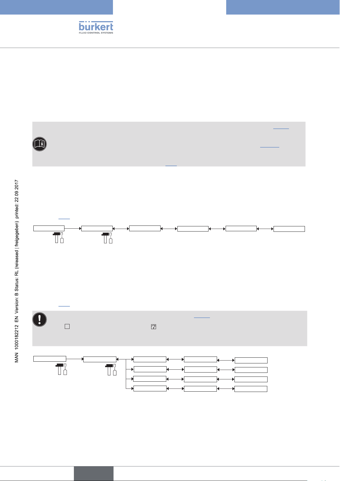
T
Type 8026 - 8036 - SE36
Adjustment and commissioning
When the device generates a "warning" or "error" event:
→ go into the "Info" menu to read the cause of the event generation.
→ and/or go into the "Sensor" function of the menu "Diagnostic" to read the measured input frequency.
→ if necessary, clean the paddle or the oval gears.
→ if necessary, check the process.
• The "warning" event may also be associated with one or both transistor outputs (see chap. 9.12.9,
function "Output.TR1" or "Output.TR2").
• The "error" event may also be associated with one or both current outputs (see chap. 9.12.10, function
"Output.AC1" or "Output.AC2").
• See also "If you encounter problems" at chap. 10.3
9.15 Knowing the menu Test
9.15.1 Modifying the Test menu access code
See chap. 9.10 to access the "Test" menu.
Test
System
Code
0***
Confirm
Enter the new
access code to the
TEST menu
If the default code (0000) is entered, the code will not be requested to access the menu.
9.15.2 Checking the output functions
See chap. 9.10 to access the "Test" menu.
• Make sure that the mode "Hold" is deactivated (see chap. 9.13.1).
• The
output has started. During the check the related output does not react according to the measured
physical value.
Test
icon is displayed in place of the icon as soon as the check for the correct working of an
Outputs
AC1
AC2
TR1
TR2
AC1 Simul:
AC2 Simul:
TR1 Simul:
TR2 Simul:
ENTER
ENTER
OFF/ON
OFF/ON
0***
Confirm the
new code
AC1: check that current output 1 is working correctly by entering a current value in mA and then selecting "OK".
AC2: check that current output 2 is working correctly by entering a current value in mA and then selecting "OK".
64
English
Page 65

T
Type 8026 - 8036 - SE36
Adjustment and commissioning
TR1: check that transistor output 1 is working correctly by selecting the status of the transistor ("ON" or "OFF")
then "OK".
TR2: check that transistor output 2 is working correctly by selecting the status of the transistor ("ON" or "OFF")
then "OK".
9.15.3 Checking the outputs behaviour
See chap. 9.10 to access the "Test" menu.
The feature allows to simulate the measurement of the physical parameter or the value of the totalizer to check if
the outputs are correctly configured.
Make sure that the mode "Hold" is deactivated (see chap. 9.13.1).
The
icon is displayed in place of the icon as soon as the check for the correct working of an output
has started. During the check the related output does not react according to the measured physical value.
Test
Sensor
PVar:
Value:
Flow_L
Flow_m3
Flow_gal
Flow_Igal
Freq.
Tot1_L
Tot1_m3
Tot1_gal
Tot1_Igal
Tot2_L
Tot2_m3
Tot2_gal
Tot2_Igal
ENTER
PVAR: choose the physical parameter or the totalizer to be tested.
VALUE: enter a physical parameter value by modifying the flow time unit or a totalizer value, depending on the
choice made in the “PVAR” function above, to check output behaviour.
65
English
Page 66

9.16 Knowing the menu Information
See chap. 9.10 to access the "Info" menu.
Type 8026 - 8036 - SE36
Adjustment and commissioning
Info
Error
Warning
Smiley
Software
Product
E:MESSAGE
W:MESSAGE
MESSAGE
Main
Sensor
READ
Soft.Main
Not set
This menu allows to read:
• a short description of the cause that generated an event related to the following icons, when they are displayed
by the device:
- ERROR:
ERR
- WARNING:
- SMILEY: or
See also "If you encounter problems" at chap. 10.3
• the software version (function “SOFTWARE”) of the acquisition/conversion board for the physical parameters
measured.
• the type, serial number and order code of the device.
66
English
Page 67
Type 8026 - 8036 - SE36
Maintenance and troubleshooting
10 MAINTENANCE AND TROUBLESHOOTING
10.1 Safety instructions
DANGER
Risk of injury due to high pressure in the installation.
▶ Stop the circulation of fluid, cut off the pressure and drain the pipe before loosening the process connections.
Risk of injury due to electrical voltage.
▶ Shut down and isolate the electrical power source before carrying out work on the system.
▶ Observe all applicable accident protection and safety regulations for electrical equipment.
Danger due to high temperatures of the fluid.
▶ Use safety gloves to handle the device.
▶ Stop the circulation of fluid and drain the pipe before loosening the process connections.
Risk of injury due to the nature of the fluid.
▶ Respect the prevailing regulations on accident prevention and safety relating to the use of aggressive fluids.
WARNING
Risk of injury due to non-conforming maintenance.
▶ Maintenance must only be carried out by qualified and skilled staff with the appropriate tools.
▶ Ensure that the restart of the installation is controlled after any interventions.
10.2 Cleaning the device
→ Clean the device with a cloth dampened with water or a detergent compatible with the materials the device is
made of.
Please feel free to contact your Bürkert supplier for any additional information.
The fouling of the paddle-wheel may result in a drift of the flow rate measurement.
→ Clean the paddle-wheel according to the type of fouling.
English
67
Page 68

10.3 Solving problems
Type 8026 - 8036 - SE36
Maintenance and troubleshooting
Red
LED
Current
output
Transistor
output
ON 22 mA depending
on
thresholds
ON 22 mA depending
on
thresholds
ON 22 mA depending
on
thresholds
Icon Message dis-
played in the
Info menu
"Sensor not
ERR
ERR
found"
"TR EE Fact
Read"
+
+
"TR EE User
Read"
"TR EE
ERR
+
UserWrite"
Possible cause Recommended action
The connection to
the measurement
→ Switch the power supply
off then on again.
module is
interrupted.
→ If the error persists, return
the device to Bürkert.
Parameter reading
error.
→ Switch the power supply
off then on again.
→ If the error persists, set the
device back to the default
settings (chap. 9.12.3).
→ If the error persists, return
the device to Bürkert.
Parameter saving
error.
→ Switch the power supply
off then on again.
→ Save the settings again.
→ If the error persists, set the
device back to the default
settings (chap. 9.12.3).
ON 22 mA
1)
depending
on
thresholds
+
"E:Frequency" The input frequency
ERR
is out of range.
This message
is displayed if
monitoring of the
input frequency is
activated, depending
on the set thresholds
ERR LO and ERR HI
(see chap. 9.14.2).
→ If the error persists, return
the device to Bürkert.
→ Go into the “Sensor”
function in the Diagnostic
menu to read the value of
the input frequency.
→ check that the paddle is
clean and that it rotates
freely on its axis
or
→ check that the oval gears
rotate freely.
→ check the installation.
68
English
Page 69

Type 8026 - 8036 - SE36
Maintenance and troubleshooting
Red
LED
Current
output
Transistor
output
OFF 4-20 mASwitched
OFF 4-20 mASwitched
OFF 4-20 mASwitched
OFF 4-20 mAdepending
on
thresholds
Icon Message dis-
played in the
Info menu
2)
2)
"W:Frequency" The input frequency
+
"W:TRnPu too
big"
2)
"W:TRnPu 1:1
set"
"W:to low
supply"
Possible cause Recommended action
→ Go into the “Sensor”
is out of range.
This message
is displayed if
monitoring of the
input frequency is
activated, depending
on the settings of the
thresholds WARN
LO and WARN HI
(see chap. 9.14.2).
function in the Diagnostic
menu to read the value of
the input frequency.
→ check that the paddle is
clean and that it rotates
freely on its axis
or
→ check that the oval gears
rotate freely.
→ check the installation.
In “Pulse” mode, the
volume entered for
a pulse is incorrect
(see chap. 9.12.10).
In “Pulse” mode, the
volume entered for
a pulse is incorrect
(see chap. 9.12.10).
The operating supply
of the device is too
low.
If a power shut down
occurs, the saving of
the totalizers is not
guaranteed.
→ Enter an appropriate
volume.
→ check the K-factor.
→ Enter an appropriate
volume.
→ check the K-factor.
→ check the electrical wiring.
→ check that the elec-
trical specifications are
inside the allowed range
(chap. 6.5)
1)
if the MODE DIAG function of the "Output.AC1" or "Output.AC2" menu is set to "22 mA" (see chap. 9.12.9); else, the
current output delivers a standard current between 4 and 20 mA
2)
If the "PVAR" function of the "Output.TR1" and/or "Output.TR2" menus is set to "warning" (see chap. 9.12.10); else, the
transistor outputs are operating depending on the set thresholds.
69
English
Page 70

Type 8026 - 8036 - SE36
Spare parts and accessories
11 SPARE PARTS AND ACCESSORIES
ATTENTION
Risk of injury and/or damage caused by the use of unsuitable parts.
Incorrect accessories and unsuitable replacement parts may cause injuries and damage the device and the surrounding area.
▶ Use only original accessories and original replacement parts from Bürkert.
Spare part (only for flowmeters type 8026) Order code
Set with 1 green FKM seal + 1 black EPDM seal 552 111
Snap ring 619 205
Nut 619 204
Accessory Order code
Display module 559 168
Set with 2 opaque covers, with seals:
- 1 screw cover with 1 EPDM seal
- 1 quarter turn closing cover with 1 silicone seal
Set with 2 transparent covers, with seals:
- 1 screw cover with 1 EPDM seal
- 1 quarter turn closing cover with 1 silicone seal
5-pin female M12 connector, moulded on shielded cable (2 m) 438 680
5-pin male M12 connector, to be wired 560 946
5-pin male M12 connector, moulded on shielded cable (2 m) 559 177
560 948
561 843
12 PACKAGING, TRANSPORT
NOTE
Damage due to transport
Transport may damage an insufficiently protected device.
▶ Transport the device in shock-resistant packaging and away from humidity and dirt.
▶ Do not expose the device to temperatures that may exceed the admissible storage temperature range.
▶ Protect the electrical interfaces using protective plugs.
13 STORAGE
NOTE
Poor storage can damage the device.
▶ Store the device in a dry place away from dust.
▶ Storing temperature for type 8026: -10 to +60°C.
▶ Storing temperature for type SE36: -10 to +60°C.
▶ Storing temperature for the fitting: refer to the related manual
70
English
Page 71

Type 8026 - 8036 - SE36
Disposal of the product
14 DISPOSAL OF THE PRODUCT
→ Dispose of the device and its packaging in an environmentally-friendly way.
NOTE
Damage to the environment caused by parts contaminated by the fluid.
▶ Comply with the national and/or local regulations which concern the area of waste disposal.
English
71
Page 72

Type 8026 - 8036 - SE36
72
English
Page 73

Page 74

www.burkert.com
 Loading...