

Page 1

TABLE OF CONTENTS
1 INTRODUCTION ......................................................................................................................... E-2
1.1 Unpacking and Control ................................................................................................................ E-2
1.2 About this Manual ........................................................................................................................ E-2
1.3 User's Responsibility for Safety .................................................................................................. E-2
1.4 Electromagnetic Compatibility ..................................................................................................... E-2
2 SPECIFICATION .........................................................................................................................E-3
2.1 Type Specification ....................................................................................................................... E-3
2.2 Design and Measuring Principle ................................................................................................. E-4
2.3 Dimensions Electronic housing SE35 Batch controller .............................................................. E-5
2.4 Technical Data ............................................................................................................................. E-6
3 INSTALLATION .......................................................................................................................... E-7
3.1 Installation Guidelines ................................................................................................................. E-7
3.2 Process Mounting ........................................................................................................................ E-8
3.3 General electrical connection ...................................................................................................... E-9
3.4 Electrical Wiring ........................................................................................................................... E-9
3.5 Electrical Wiring with Power Supply 230/115 VAC...................................................................E-10
4. OPERATION AND CONFIGURATION.....................................................................................E-11
4.1 Controller operating and Control elements ............................................................................... E-11
4.2 Description of the Dosing Options ............................................................................................ E-12
4.2.1. «LOC.MANU» Option......................................................................................................E-12
4.2.2. «LOC.MEM» Option ....................................................................................................... E-12
4.2.3. «MEM+MANU» Option....................................................................................................E-12
4.2.4. «EXT.MEM» Option ........................................................................................................ E-13
4.2.5. «EXT.[T]» Option ............................................................................................................ E-14
4.3 Main menu .................................................................................................................................E-15
4.3.1. Dosage in manual mode .................................................................................................E-15
4.3.2. Dosage in automatic mode ............................................................................................. E-16
4.3.3. Dosage proportional to a pulse duration ........................................................................ E-17
4.3.4. Display of flow rate and the initial preset volume during the dosage ............................ E-17
4.3.5. Pause / reset function ..................................................................................................... E-18
4.4. Calibration Menu ....................................................................................................................... E-19
4.4.1. Language.........................................................................................................................E-19
4.4.2. Measurement units ..........................................................................................................E-20
4.4.3. K-Factor ........................................................................................................................... E-20
4.4.4. Dosing options.................................................................................................................E-21
4.4.5. Overfill correction ............................................................................................................ E-23
4.4.6. Alarm ............................................................................................................................... E-23
4.4.7. Relays ..............................................................................................................................E-24
4.4.8. Totalizer ........................................................................................................................... E-26
4.5. Test Menu .................................................................................................................................. E-26
4.5.1. EXT.ACT. ........................................................................................................................ E-26
4.5.2. Check on operation of relays ..........................................................................................E-27
4.5.3. Transducer frequency readout........................................................................................E-27
5. MAINTENANCE ........................................................................................................................ E-28
5.1 Fault prompts ............................................................................................................................. E-28
5.2. Transducer maintenance...........................................................................................................E-30
5.3. Default configuration of 8035 INLINE Batch controller on delivery ..........................................E-31
5.4 Spare Parts List .........................................................................................................................E-31
BATCH CONTROLLER SE35
APPENDIX ................................................................................................................................. A-1
Flow Chart (l/min, DN in mm and m/s)........................................................................................A-1
Flow Chart (US-gallon/min, DN in inch and Ft/s) ....................................................................... A-2
8035
E-1- Ref. 419744
Page 2

1 INTRODUCTION
Dear Customer,
BATCH CONTROLLER SE35
Congratulations on your purchase of our
batch controller SE35 INLINE.
Before installing or mounting this device,
please take our advice and read the entire
manual thoroughly.
This will enable you to fully profit from all of
the advantages offered by this product.
1.1 Unpacking and Control
Please verify that the product is complete
and free from any damage. The standard
delivery must include:
-1 Batch Controller electronic SE35
-1 Instruction manual SE35
-1 Instruction manual S030 Inline
Compare the type specification on the
label to the following list to ensure that
you have received the proper unit.
If there is any loss or damage, please contact
your local Bürkert subsidiary.
1.2 About this Manual
1.3 User's Responsibility for Safety
Bürkert manufactures a broad range of flow
sensors. While each of these products is
designed to operate in a wide variety of
applications, it is the user's responsibility to
select a controller model that is appropriate
for the application, install it properly, and
maintain all components. Special attention
must be paid to the chemical resistance of
the sensor against the fluids which are
directly contacting the product.
This symbol appears in the
manual to call special attention
to instructions that affect the safe
!
installation, function and use of
the product.
1.4 Electromagnetic compatibility
This device conforms to the EMC-Directive
of the European Community 89/336/EEC.
In order to comply with this directive, the
wiring instructions must be followed.
This manual does not contain any warranty
statement. Please refer to our general terms
of sale and delivery.
Only properly-trained staff should install and/
or repair this product. If difficulties
should occur at the time of installation,
please contact your nearest Bürkert sales
office for assistance.
E-2-
8035
Page 3

2 SPECIFICATION
BATCH CONTROLLER SE35
2.1 Batch controller electronic SE35 Batch INLINE,
The batch controller 8035 is consisting of a S030 fitting which houses the paddle-wheel
and an electronic controller SE35, specially designed to be installed on the fitting.
Use a separate order N° for the S030 Fitting. For more informations about the fittings see
the corresponding instruction manual.
International Standard Version Cable Input Order Nr
Batch Controller SE35, Power Supply 12-30 VCC
2 totalizers, 2 relays 2 x PG 13,5 423920
Batch Controller SE35, Power Supply 115-230 VAC
2 totalizers, 2 relays 2 x PG 13,5 423926
North-America Standard Version Cable Input Order Nr
Batch Controller SE35, Power Supply 12-30 VCC
2 totalizers, 2 relays 2 x PG 13,5 423932
Batch Controller SE35, Power Supply 115-230 VAC
2 totalizers, 2 relays 2 x PG 13,5 423937
8035
E-3-
Page 4

2 SPECIFICATION
2.2 Design and Measuring Principle
Design
BATCH CONTROLLER SE35
The Batch Controller SE35 Inline consists
of an electronic IP65 housing SE35 set by
quarter turn on the fitting S030. The
electronic housing integrates the electronic
board with display, programmation keys and
also a the transducer. The paddle-wheel is
mounted in the fitting.
The transducer component converts the
measured signal and displays the actual
value.The output signals are provided via
two PG 13.5.
Measuring and Dosing Principle
When liquid flows through the pipe, 4
magnets inserted in the paddle-wheel set in
rotation produce a measuring signal in the
transducer.
The frequency modulated induced voltage
is proportional to the flow velocity of the fluid.
A conversion coefficient, specific to each
pipe (size and material) enables the
conversion of this frequency into flowrate.
This coefficient (Factor-K in pulse/liter) is
available in the instruction manual of the
inline fitting (S030).
The controller electronic module SE35
Batch requires a power supply of 12...30
VDC (230/115 VAC as option).
Dosing options
Following dosing modes are available
I) Local dosing command:
a) The user enters the volume to be
measured and initiates the dosing from the
keypad. ("LOC.MANU") (§ 4.3.1)
b) Local dosing with preset volumes.
Selection of a pre-set volume and activation
of the process from the keypad.("LOC.MEM").
(§ 4.3.2)
c) Combination from "LOC.MANU" and
"LOC.MEM" options. activated from the
keyboard ("MEM+MANU") (§ 4.3.1 + § 4.3.1).
II) Remote dosing command:
a) Dosing controlled by binary inputs issued
from a PLC. Each pulse controls the dosing
of a preselected volume.("EXT.MEM") (§ 4.3.4)
b) Automatic dosing controlled by the pulse
duration. The ditributed volume is directly
proportionnal to the pulse duration ("EXT .
[T]") (§ 4.3.3)
The controller SE35 Batch is mounted on a
pipe in series with the valve. The SE35 unit
measures the flow, calculates the volumes,
and operates the valve(s) according to the
selected program (see § 4).
E-4-
8035
Page 5
2 DESCRIPTION
BATCH CONTROLLER SE35
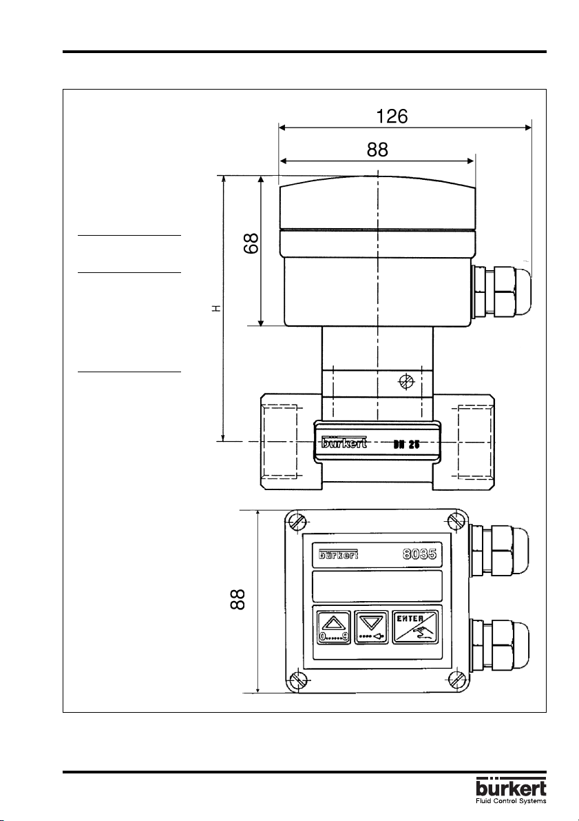
2.4 Batch Controler 8035 INLINE external dimensions (mm)
DN H
mm "
15 122 4.81
20 119 4.69
25 120 4.73
32 123 4.85
40 127 5.00
50 134 5.28
The height H is
independant from the
connection type and
material of the fitting.
Fig. 1 Batch Controler 8035 INLINE external dimensions
8035
E-5-
Page 6
2 SPECIFICATION
BATCH CONTROLLER SE35
2.4 Technical Data
Pipe diameter from DN 15 to DN 50 (1/2" to 2")
Measuring range 0,3 to 10 m/s (1.0 to 32.8 ft/s)
flow range as from 3 l/min (DN15 pipe, 0.3 m/s flow velocity)
flow range as from 0.8 gpm (1/2" pipe, 1.0 ft/s flow velocity)
Plastic fitting PN10
Fluid temperature max PVC: 50 °C (132°F); PP: 80 °C (176°F); PVDF: 100 °C (212°F)
Metal fitting PN16
Fluid temperature max: 100 °C (212°F)
Ambiant temperature 0 to 60 °C (32 to 140 °F)
Storage temperature 0 to 60 °C (32 to 140 °F)
Relative humidity 80 %
Enclosure IP65
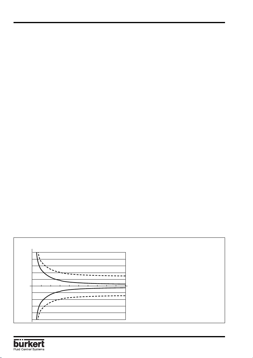
Measuring error 1.With In-line calibration (Teach-In):
≤± 0.5% o.F.S. (at 10 m/s) *
2.With standard mean K-Factor:
≤ ± (0.5% o.F.S. +2.5% o.R.) *
Linearity ≤ ± 0.5% o.F.S. (at 10 m/s) *
Repeatability 0.4% o.R. *
Display 15 x 60 mm LCD 8 digits, alphanumeric,
Sensor holder PVDF, PP, PVC, SS 316L (1.4404), Brass
Paddle-wheel PVDF
Axis and bearing ceramic
O-rings FPM
Electronics housing PC; Front plate foil polyester
Voltage supply 12...30 VDC (230 VAC power supply as option )
Binary inputs 4 inputs, 5...30 VDC
15 segments, 9 mm high
Relay output 2 relays, 3 A, 220 V, freely adjustable
(*) Under reference conditions i.e. measuring fluid water, ambient and water temperature 20°C,
applying the minimum inlet and outlet pipe straights, matched pipe dimensions.
o.F.S. = of standard Full Scale (10 m/s) - o.R. = of Reading
% max.
error
10
8
6
4
2
-2
-4
-6
-8
Measuring error % of measured value (*)
-10
0
.
5
%
o
.
F
.
S
.
+
2
.
5
%
0
.
5
%
o
.
F
.
S
.
19
2345 6 78 10
Flow velocity m/s
o
.
R
.
with standard K-factor
with Teach-In
m/s
Measuring error with/without Teach-In
E-6-
8035
Page 7
3 INSTALLATION
BATCH CONTROLLER SE35
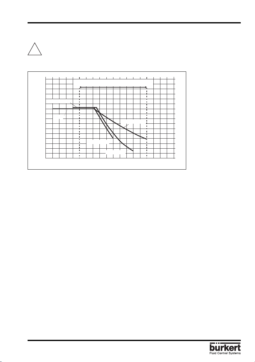
3.1 Installation Guidelines
The controller SE35 Batch INLINE can only be used to measure pure, liquid and
!
water-like fluids (solids content ≤ 1%, viscosity max. 300 cSt with on-line calibration).
Observe pressure-temperature dependence according to the respective fitting materials.
P
16
bar
15
14
13
12
PVC + PP
11
10
9
PVDF
8
7
6
5
4
3
2
1
0
-30
-50
Fig. 2 Pressure-Temperature-Diagram
Application range for SE35 INLINE
PVDF (PN 10)
PVC (PN 10)
PP (PN 10)
-10 +10
+30
+50 +70
+90
+110 +130
T° C
Fitting S030 installation guidelines
The pipe must be completely filled with the
liquid, i.e. air bubbles must not be present.
The flow sensor is not designed for gas flow
measurement.
The device must be protected from constant
heat radiation and other environmental
influences, such as direct exposure to
sunlight.
The recommended upstream and
downstream straight pipe length should
respect 10xD in and 3xD out.
According to pipe's design, necessary
distances can be bigger or use a flow
straightener to obtain the best accuracy.
For more information please refer to EN ISO
5167-1.
8035
The flow sensor can be installed in either
horizontal or vertical pipe.
The suitable pipe size is selected using the
diagram on the end pages. Pressure and
temperature ratings must be respected
according to to the selected fitting material.
(see fig. 2)
E-7-
Page 8
3 INSTALLATION
BATCH CONTROLLER SE35
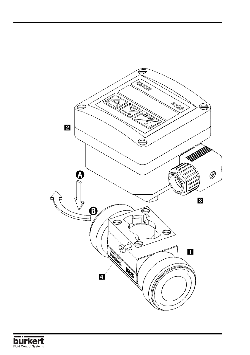
3.2 Process mounting
The flow controller electronic module SE35 Batch INLINE can be easily installed in pipes
using the specially designed fitting system S030 INLINE.
1.The fitting must be installed into the
pipe according to the installation
specifications (see § 3.1).
2.Fasten the electronic
housing to the
fitting using the
bayonet connection,
and turn by 30°.
Wiring instructions § 3.4
3.Tighten the electronic
housing with the screw
.
Fig. 3 Batch controller 8035 INLINE Batch mounting diagram
E-8-
8035
Page 9
3 INSTALLATION
BATCH CONTROLLER SE35
3.3 General Electrical Connection
The connecting cable conducts the input/output signals and must not be installed in
combination with high voltage or high frequency carrying lines. If a combined installation
cannot be avoided, either keep a min. space of 30 cm (approx. 1 ft) or use coax cables.
When using coax cables observe faultless grounding of the shield. For normal operating
conditions, the input/output signal can be transmitted by a simple cable of 0.75 mm2 cross
section.
The power supply must be of good quality (filtered and regulated).
Note: For EMC purposes,the earth must be connected via the earth lug on the side
of the enclosure. This point must be connected locally to a good earth.
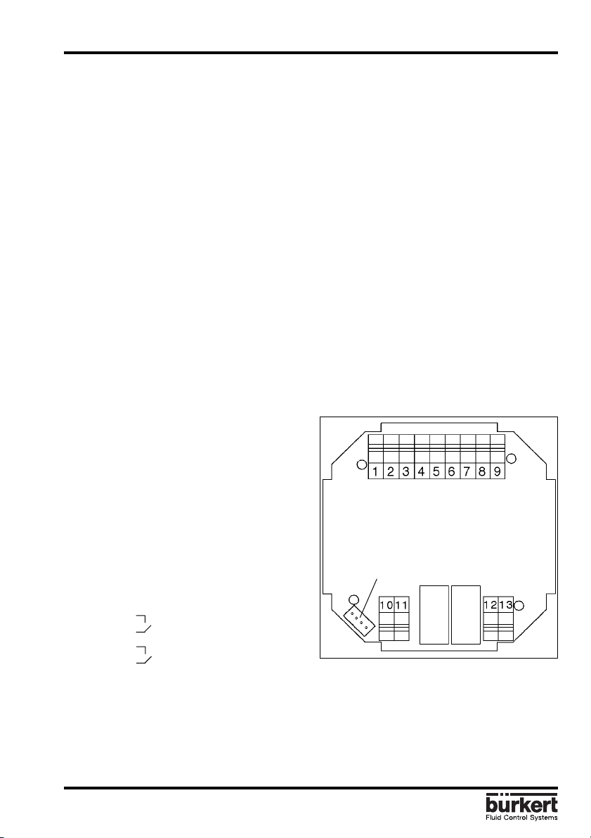
3.4 Electrical connection SE35 Batch
The connections are made via the two 13,5 cable glands.
Remove cover, pull the cable through a PG
13.5 and wire according to following pin
assignment and fig. 4:
1: Binary input 1
2: Binary input 2
3: Binary input 3
4: Binary input 4
5: Indicator lamp output (Transistor Open
Collector)
6: Common (binary inputs and outputs)
7: L+ (12...30 VDC)
8: L9: Earth
10: Relay 2
11: Relay 2
12: Relay 1 Main valve
13: Relay 1 see § 4.4.7
Note: The driver unit supply voltage can be used for the binary inputs and the indicator
lamp output (open collector). In this case the common terminal (6) and the L- terminal (8)
should be connected together.
8035
Fig. 4 Pin assignment SE35 Batch
E-9-
Sensor connection
Page 10
3 INSTALLATION
BATCH CONTROLLER SE35
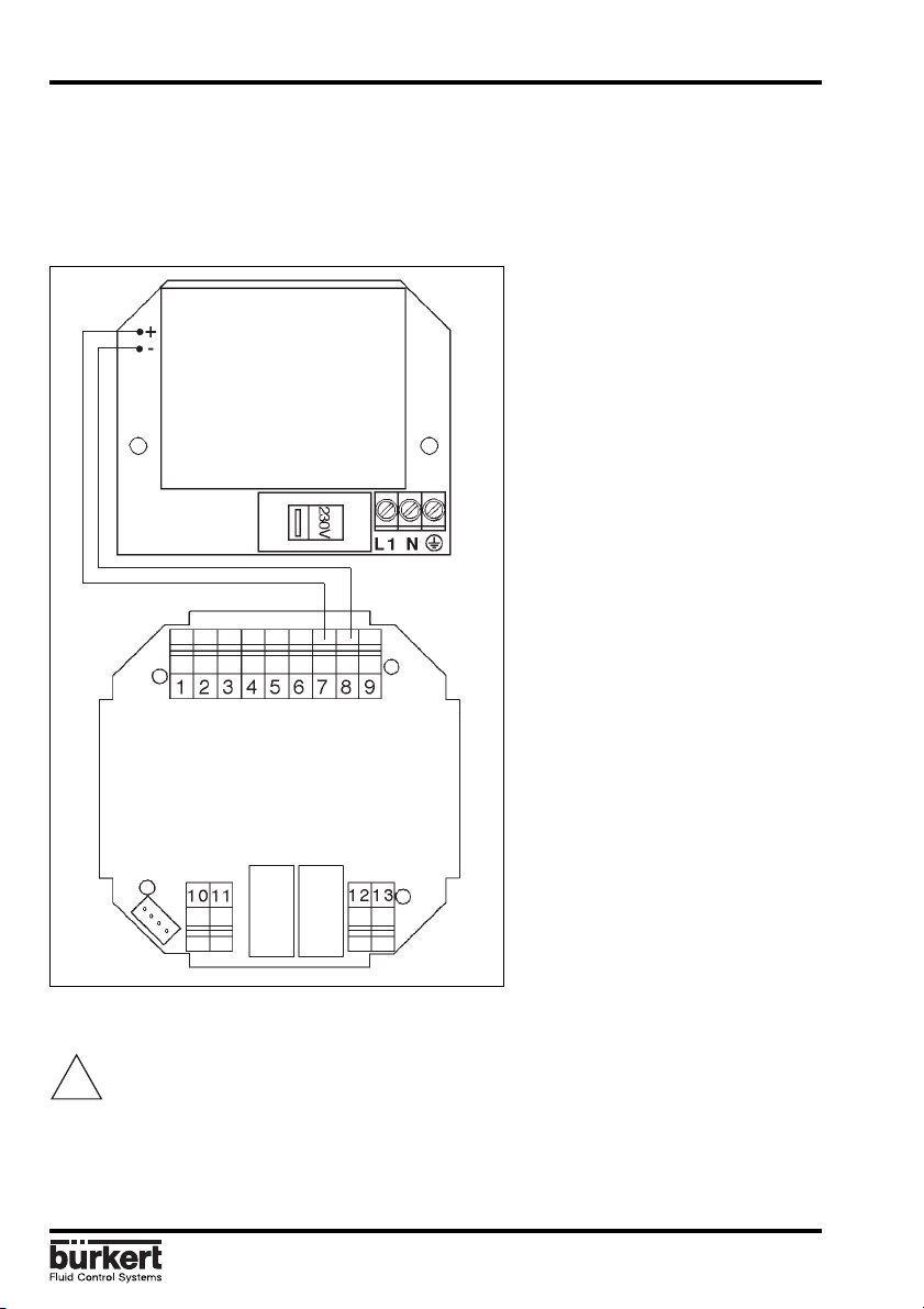
3.5. Electrical Connections for a Supply Voltage of 230/115 VAC (option)
Remove the cover from the unit, the power supply board is on the bottom of the housing.
Pull the cable through a PG 13.5 cable gland and wire according to fig. 5. The other
connections will be the same as on the standard version § 3.4.
Sensor connection
Fig. 5 Connection diagram for controller 8035Batch 230V /115 V AC option
Important: The 230/115 VAC version doesn't allow the driver unit power supply to
!
be used for the binary data inputs and the indicator lamp output (open collector).
E-10-
8035
Page 11
4 OPERATION
BATCH CONTROLLER SE35
The operation is classified according to three levels.
A) Display
This menu allows the user to control the dosing by the keypad (start, pause, reset, stop);
using the LCD display, he can monitor the flow rate and the initial preset volume throughout
the dosing operation. The readings of the main counter and the daily counter are displayed
within this menu. The daily counter can be set to zero.
B) Parameter Definition
This menu enables the setting of dosing parameters (languages, measurement units,
equipment, K factor, dosing option, overfill correction, alarm and relay thresholds).
Simultaneous resetting of the two counters is carried out within this menu.
C) Testing
This menu enables the user to check the binary inputs (remote control) and to simulate the
operation of the relays.
It also caters for measuring the rotation frequency of the paddle wheel.
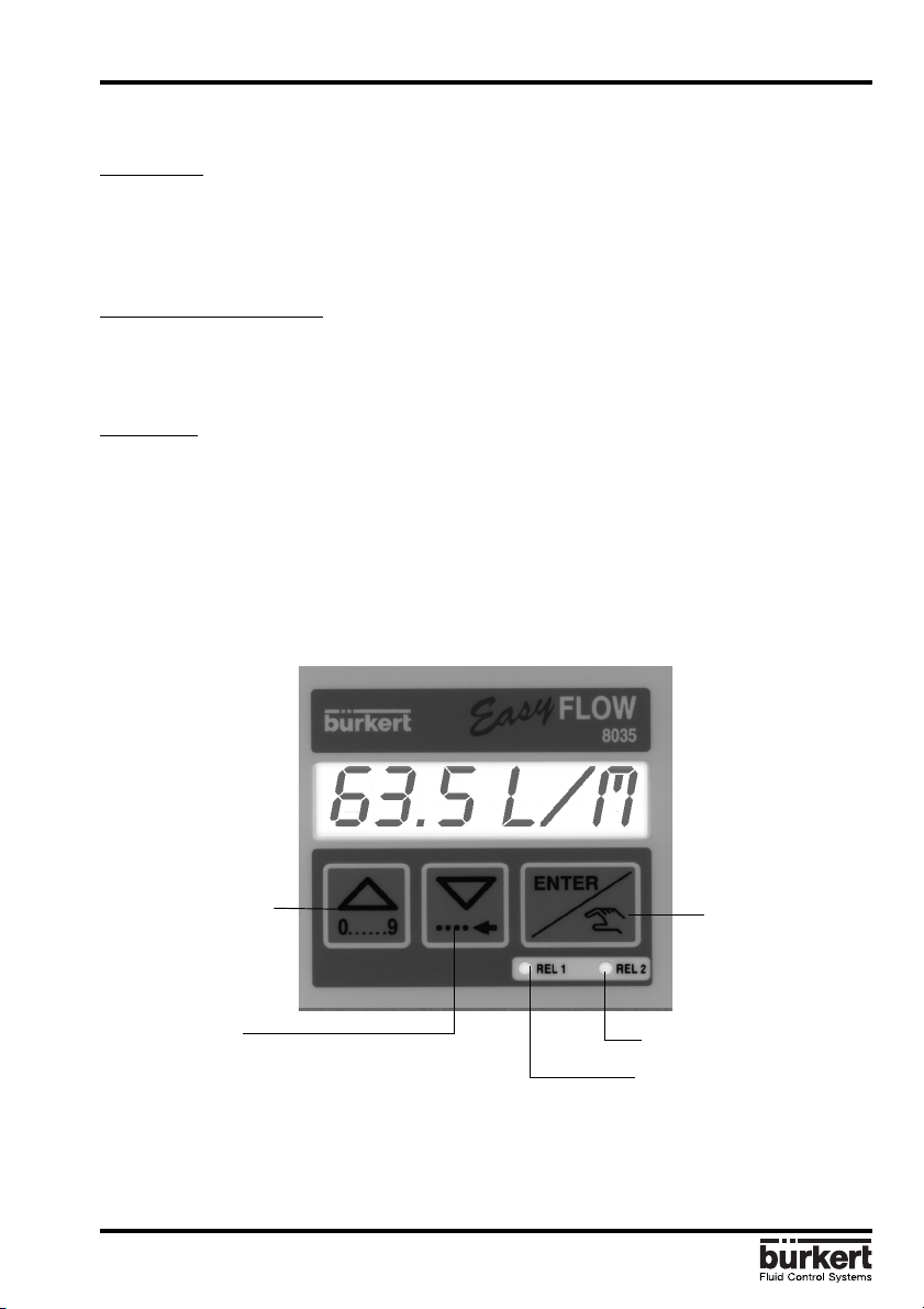
4.1 Controller Operating and Control Elements
Choice of digit value
Steps from 0 to 9
Menu selection
Direction
downwards in
menu or
sideways for digit
selection
8035
Accept of
choosen
parameter or
adjusted value
Relay 2 (contact closed)
Relay 1(contact closed)
E-11-
Page 12

4 CONFIGURATION
BATCH CONTROLLER SE35
4.2 Description of Dosing Options
Dosing options are selected within the «OPTION» sub-menu of the Calibration Menu. ( §
4.4.4.)
4.2.1. «LOC.MANU» Option»
When this option is selected, the prompt «BATCH M» is displayed within the main menu. It
enables the generation of a volume which can be defined using the keypad. (see § 4.3.1.)
4.2.2. «LOC.MEM» Option
When this option is selected, the prompt «BATCH A» is displayed within the main menu.
Generation of a volume previously entered into the memory (7 in total) from the keypad
(see § 4.3.2.).
4.2.3.»MEM+MANU» Option
When this option is selected, the prompts «BATCH M» and «BATCH A» are displayed within
the main menu.
Generation of a volume either manually or automatically. (see § 4.3.1 and § 4.3.2).
E-12-
8035
Page 13

4 CONFIGURATION
BATCH CONTROLLER SE35
4.2.4 »EXT.MEM» Option
Generation of a volume previously entered into the memory (7 in total) from a remote
position by using the binary data inputs (See § 4.2.2.). The following example describes
the various methods of connection.
L+(12...30VDC)
GND
123456789
S/S
LED
쏏
쏏
쿘
+ - 쵰
COM
PLC, switch, push button,
etc.
Batch controller
8035 INLINE
PE
GND
L+(12...30VDC)
Fig. 6 Connection to a PLC
The selection of a volume from the memory (1 to 7) is carried out by encoding the binary
data at inputs 1,2 and 3. The following table shows the logic value at each input to provide
each of the desired seven quantities:
Volume V1 V2 V3 V4 V5 V6 V7
Input 1 1 010101
Input 2 0 110011
Input 3 0 001111
1: Input enabled (switch closed)
0: Input disabled (switch open)
Input 4: Start / Pause function (from a push button, for example).
Output 5: Transistor output (open collector)
Provides Batch controller status information. For example, it can be used to feed an
indicator lamp.
The following status can be indicated:
Lamp off No dosing in progress
Lamp on Dosing in progress
Slow flashing (1 Hz) Pause in dosing operation
Rapid flashing (3.5 Hz) Alarm (problem during dosing operation)
8035
E-13-
Page 14

4 CONFIGURATION
BATCH CONTROLLER SE35
4.2.5. «EXT. [T]» Option
Delvery of a volume proportional to the duration of the high level on the input 1
(see § 4.3.3.). The proportional relationship is as follows:
X = Volume = (A x t) +B A Coefficient of proportionality (/s;...)
B Offset (l;...)
t Duration of input 1 activation (ms, s;...)
X Dosing volume (l;...)
Coefficients A and B entered by the user.
Pulse specification
T
: 100 ms
min
T
: 300 s
max
Definition: 5 ms
Delay between 2 pulses: min 100 ms
Practical examples:
- Filling cans of 5, 10 and 50 litres respectively. The following values can be entered:
A = 5 l/s
B = 0 l
The activation times for binary data input 1 for the three volumes are as follows:
Volume (l) 5 10 50
Duration (s) 1 2 10
- Doses of chemical products as a function of required concentration. Volumes of 110,
120, 130, and 150 litres. The following values can be entered:
A = 5 l/s
B = 100 l
The activation times for binary data input 1 for the three volumes are as follows:
Volume (l) 110 120 130 150
Duration (s) 2 4 6 10
Notes:
- The activation time for the binary data input must always be lower than the actual filling
time. A margin of safety should be allowed when choosing the coefficients A and B.
- The coefficients A and B should be chosen such that the activation times for the binary
data input should be efficient. In the example , one could have choosen A = 100 l/s and
B = 0 l. The resulting activation times would be 1.1, 1.2, 1.3 and 1.5 seconds. In this case
the distributed doses would be less accurate.
E-14-
8035
Page 15

4 CONFIGURATION
BATCH CONTROLLER SE35
4.3 Main menu
Within the main menu, following readouts are available:
BATCH M
Dosing in manual mode (see § 4.3.1.).
Only available if the «LOC.MEM» or the «MEM+MANU» Options
have been selected within the Calibration menu (see § 4.4)
0......9
BATCH A
Dosing in automatic mode (see § 4.3.2.).
Only available if the «LOC.MEM» or the «MEM+MANU» have been
selected within the Calibration menu (see § 4.4)
24563 L
456 L.
Main counter using the selected measurement unit (see
Calibration menu). Zero setting within the Calibration menu.
Daily counter using the same measurement unit as the main
counter. A decimal point after the unit differentiates it from the
main counter. Zero setting by simultaneously pressing the two
keys for 3 seconds.
0......9
The following sub-routines describe the various dosing options together with the prompts
displayed within the main menu. The GREY CHARACTERS are flashing when displayed.
4.3.1.Dosing in manual mode»LOC.MEM» or «MEM+MANU» Options
Generation of a volume previously entered from the keypad.
BATCH M
ENTER
00000 L
Entering of
volume
0......9
00100 L OK Y/N
ENTER
Countdown of
*
ENTER
volume to 0
00100 L
* You can also start the dosage using
the “Start/Pause” binary data input
(see 4.2.4).
OK Y/N
ENTER
The volume must be greater than 6 pulses generated by the paddle-wheel. The entry of
a zero volume forces a return to the «BATCH M» option.
The «ALARM» prompt during a dosing operation signifies a dosing problem (see § 5.1).
During the measure of the selected volume, displaying the flow rate, pause, reset or stop
the dosing operation. (see § 4.3.4.; § 4.3.5.) are still possible.
8035
E-15-
Page 16

4 CONFIGURATION
BATCH CONTROLLER SE35
4.3.2. Dosing in automatic mode («LOC.MEM», «MEM+MANU», or «EXT.MEM» Options)
Generation of the volume from one of the 7 values previously entered into the memory.
The selected volume can be initiated either from the keypad or by the binary inputs.
Initiating the dosing from the keypad («LOC.MEM», «MEM+MANU» Options)
1 sec.
*
BATCH A
ENTER
V1 250 L
V2 50 L
V7 1250 L
ENTER
END
ENTER
OK Y/N
OK Y/N
* You can also start the
dosage using the “Start/
Pause” binary data input
(see 4.2.4).
ENTER
ENTER
Zero quantities (from V1 to V7) will not be displayed.
Initiating the dosing from the binary data inputs («EXT.MEM» Option)
1
2885 L
Choice of volume from
memory by encoding the
binary data inputs 1, 2 and 3.
2
3
1 sec.
V2 50 L
Enabling of input 4
(push button for example)
to initiate dosing
4
Countdown of the
volume to 0
38 L
«ALARM» prompt during dosing operation: dosing problem (see § 5.1.)
Countdown of the
volume to 0
250 L
During the dosing of the selected volume, it is possible to display the flow rate, to pause,
to reset or to stop the operation (see § 4.3.4. and § 4.3.5)
E-16-
8035
Page 17

4 CONFIGURATION
BATCH CONTROLLER SE35
4.3.3. Dosing proportional to a pulse duration («EXT.[T]» Option)
This option enables the initiation of a dosing volume proportional to the time during which
binary data input 1 is enabled. The following prompts are displayed within the principal
menu during the dosing operation.
Countup of the
Totalizer
display
2885 L
1
Activation time
proportional to
dosing volume
volume to dose
38 L
Fig. 9 Exemple of electrical connection
L+(12...30VDC)
GND
123456789
S/S
LED
쏏
쏏
쿘
+ - 쵰
COM
PLC, switch, push
button, etc.
Batch controller
8035 INLINE
PE
GND
L+(12...30VDC)
«ALARM» prompt during the dosing operation: dosing problem (see § 5.1.).
During the dosing of the selected volume, it is possible to display the flow rate, to pause,
to reset or to stop the operation. These facilities are only selected on the keypad. (see §
4.3.4. and § 4.3.5)
4.3.4. Display of flow rate and the initial preset volume during the dosing.
To display the flow rate and of the initial preset volume values during the dosing operation,
press the key briefly. This is a useful facility irrespective of the dosing option chosen.
Countdown of the
dosing operation
in progress
221 L
Initial preset volume Flow rate
250 L
2 s.
2.34 L/S
2 s.
Automatic refresh after 2 s
8035
E-17-
Page 18

4 CONFIGURATION
BATCH CONTROLLER SE35
4.3.5. Pause / reset function
A current dosage can be momentarily or definitively stopped (except mode EXT [T]).
a) Modes MEM+MANU, LOC.MEM, LOC.MANU :
Countdown of the
dosage operation in
progress
221 L
ENTER
CONTINUE
*
RESET
ENTER
221 L
*
ENTER
Device ready for a
new batch (see 4.3.1)
Current batch
continues
*
* When in mode MEM+MANU, LOC.MEM or LOC.MANU, you can also start the
dosage using the 'Start/Pause' Binary Data Input.
b) Mode EXT.MEM :
Countdown of the dosage
operation in progress
4
Pause
**
4
**
CONTINUE221 L
1
2
3
"zero" position: no
input is enabled
221 L
RESET
Current batch
continues
Device ready
**
4
(see 4.3.2)
for a new
batch
c) Mode EXT [T] :
221 L
4
Pause
**
CONTINUE
Choice "Reset" can only be
made on keypad.
RESET
**
4
4
221 L
Device ready
**
for a new batch
Current batch
continues
(see 4.3.3)
(**) When in mode EXT.MEM or EXT [T], you can also press the Enter key on the keypad.
E-18-
8035
Page 19

4 CONFIGURATION
BATCH CONTROLLER SE35
4.4. Calibration Menu: pressing simultaneously for 5 seconds
Within this menu, the following parameters may be set:
LANGUAGE
K-FACTOR
OPTION
OVERFILL
ALARM
RELAY
TOTAL
Choice of language used for prompts (German, English, French,
Italian, etc.)
Choice of measurement unit used for volume, flow rate and
UNIT
counters.
Entry of K factor or automatic evaluation using the «Teach in»
function.
Choice of the dosing mode
Overfill correction taken into account or not
Choice of options and programming of the time delay before the
alarm is triggered off.
Allocation of relay parameters: function, delay, inversion, etc.
Simultaneous resetting of both totalizers.
Return to main menu and entering the new Calibration parameters.
END
ENTER
4.4.1 Language
LANGUAGE
UNIT
8035
ENTER
ENTER
ENGLISH
DEUTSCH
FRANCAIS
ITALIANO
The required language becomes
operational when the ENTER key is
pressed.
E-19-
Page 20

4 CONFIGURATION
4.4.2 Unit
ENTER
UNIT BATCH
ENTER
BATCH CONTROLLER SE35
LITER
LITER
M3
ENTER
LIT/SEC
LIT/MIN
LIT/H
M3/MIN
M3/H
UGAL/SEC
UGAL/MIN
UGAL/H
IGAL/SEC
IGAL/MIN
IGAL/H
m
0......9
US GAL
IMP GAL
TOTAL
ENTER
ENTER
LITER
M3
US GAL
IMP GAL
K-FACTOR
ENTER
Note: Return to the main menu is only available from the «TOTAL» Sub-Menu.
4.4.3 K-factor
The K-factor of the fitting is entered within this menu (see instruction manual fitting S030).
The "TEACH IN" function allows the practical determination of the specific K-factor. The
user only needs to run a known volume through his system.
Example: In order to determine a volume as accurately as possible, the user shall fill a tank
of 100 l. When the message "TEACH YES" appears, he presses the ENTER key to start the
measuring procedure. The message "FILL END" (end of filling) will appear. He then switches
on a pump or opens a valve. As soon as the tank is empty, he switches off the pump or
closes the valve. Pressing Enter stops the measurement. The user will then be asked to
enter the volume (100 l). The calculated K-factor is displayed after confimation.
E-20-
8035
Page 21

4 CONFIGURATION
BATCH CONTROLLER SE35
Note: The device uses the last K-factor entered or determined .
K-FACTOR
ENTER
TEACH N
OPTION
TEACH O END DOSE
OPTION
Note: A decimal point can be entered by simultaneously pressing keys . It will
ENTER
ENTER
ENTER
Start of measurement.
Indication of calculated
K-factor.
K=000.00
0......9
K=046.60
K=044.12
Entering of K-factor as
specified in the charts.
ENTER
Stop of
measurement.
Entering the measured
volume. Same unit as for flow.
ENTERENTER
0000.0 L
0......9
0200.0 L
0......9
always be positioned to the right of the flashing digit. Three positions are possible, «00000»,
«0000.0» or «000.00».
Adjustment range for the K factor : 0,01 to 99999.
4.4.4. Dosing Options
Selection the dosing option from: LOC.MEM, LOC.MANU, MEM+MANU, EXT.MEM, and
EXT.[T].
For more information on these options, see § 4.2
8035
E-21-
Page 22

4 CONFIGURATION
BATCH CONTROLLER SE35
OPTION
OVERFILL
OVERFILL
OVERFILL
OVERFILL
ENTER ENTER
LOC.MEM
LOC.MANU
+
MANU
MEM
EXT.MEM
ENTER
ENTER
ENTER
V1
=
00000
0......9
V1
=
00100
V1
=
00000
0......9
V1=00100
V1
=
00000
0......9
V1
=
00100
ENTER
ENTER
ENTER
V7
V7
V7
V7
V7
V7
=
00000
=
00700
=
00000
=
00700
=
00000
=
00700
0......9
ENTER
0......9
ENTER
0......9
ENTER
EXT. [T] A
OVERFILL
When entering volumes (quantities) V1 to V7, the measurement unit which applies is that
which was selected for the the dosing volume (see Calibration Menu).
Note: A decimal point can be entered by simultaneously pressing keys . It will
always be positioned to the right of the flashing digit.
ENTER
E-22-
=
0000/S
=
0005/S
A
0......9
ENTER
ENTER
=
B
B
=
0050 L
0......9
0000 L
0......9
8035
Page 23

4 CONFIGURATION
BATCH CONTROLLER SE35
4.4.5. Overfill correction
The 8035 Batch controller has an overfill correction facility. It memorises the fluid volume
which flows after the closure of the valve so that this volume can be deducted from the next
batch. In this sub-menu the user enables or disables the overfill correction facility.
OVERFILL
ALARM
ENTER
ENTER
OVERF. NO
OVERF. Y
4.4.6 Alarm
The menu makes it possible to enable or disable the trigger-off of the alarm during a
dosage (DURING option) and/or after a dosage (AFTER option). It also makes it
possible to program the time delay before the alarm is triggered off, for either option.
The alarm display prompt is «
ALARM
». This alarm data prompt is also available on tag
strip terminal N°. 5 (transistor output, open collector) and on Relay N° 2 if this relay
has been configured as an alarm relay (see next paragraph).
For the conditions required to trigger off the alarm, see Section 5.
ALARM
ENTER
DURING
ENTER
ON
OFF
ENTER
ENTER
DEL1= 000
0......9
DEL1
=
015
ENTER
AFTER
ENTER
ON
ENTER
DEL2
DEL2
=
=
000
0......9
015
OFF
ENTER
ENTER
RELAY
Range of adjustment: between 0 and 999 seconds.
Remark: The time delay before the alarm is triggered off must take into account the
overfill correction if enabled.
8035
E-23-
Page 24

4 CONFIGURATION
4.4.7. Relays
The 8035 Batch controller provides 2 relays:
- Relay 1 controls the opening of the main valve (high flow rate). A delay before activation
may be selected and the operating polarity may be inverted; the user also has the facility
of setting the percentage of the selected volume to be delivered through the main valve
(high flow rate). This implies that the Relay 2 controls an auxiliary valve (low flow rate) in
order to provide the remainder of the entire selected volume.
- Relay 2 can be configured for three different functions: Alarm, End of the dosing and
Control of an auxiliary valve. In each configuration the operating polarity can be inverted.
BATCH CONTROLLER SE35
E-24-
8035
Page 25

4 CONFIGURATION
BATCH CONTROLLER SE35
RELAY
TOTAL
ENTER ENTER
RELAY 1
RELAY 2
ENTER
=
000
DEL
0......9
=
020
DEL
INV NO
INV YES
ALARM
END DOSE
ENTER
ENTER
ENTER
ENTER
ENTER
100 %
0......9
85 %
INV NO
INV YES
ENTER
INV NO
INV YES
TOTAL
VALVE
ENTER
ENTER
INV NO
INV YES
TOTAL
Notes:
- If Relay 1 is configured for a percentage flow rate different from 100, then Relay 2 will
automatically be configured for valve control. The other options will no longer be available.
- Relay 1 will not open the valve until the entered delay period has elapsed.
8035
E-25-
ENTER
Page 26

4 CONFIGURATION
4.4.8 Totalizer
Simultaneous setting of both counters to zero. This facility becomes operational when the
user presses the ENTER key while in the «END» option within the Calibration menu.
BATCH CONTROLLER SE35
TOTAL
ENTER
RES NO
RES YES
END
4.5 Test Menu: Press simultaneously for 5 s.
The following adjustments and checks are carried out in the Test Menu:
ENTER
0......9
EXT.ACT.
RELAY 1
RELAY 2
FREQUENC
END
ENTER
Verification of the binary data inputs in mode «EXT.MEM».
Readout of Pulse duration in «EXT.[T] mode.
Check on relay 1 operation.
Check on relay 2 operation.
Transducer frequency readout
Return to the Main Menu and the setting of new parameters.
4.5.1 EXT.ACT.
This sub-menu provides for checking the allocation of binary logic levels to the binary data
inputs under the «EXT.MEM» dosing option and also provides a readout of the pulse duration
under option «EXT [T]».
«EXT.MEM» Option
EXT.ACT.
RELAY 1
ENTER
V 1 V4
Readout of quantities corresponding to the coding of the binary
ENTER
inputs (by using the rotary knob, for example). If the readout
shows «--» the coding of the inputs corresponds to a zero volume.
E-26-
8035
Page 27

4 CONFIGURATION
«EXT. [T] Option
In this option, the user can check the pulse duration being sent to the 8035 Batch controller.
EXT.ACT.
RELAY 1
4.5.2. Check on operation of relays
This option allows the operator to check for correct operation of the relays by using the
keypad to energise the relays.
ENTER
0.00 SEC
Start of pulse End of pulse
ENTER
BATCH CONTROLLER SE35
. . . . SEC
5.35 SEC
RELAY 1 REL OFF
ENTER
ENTER
REL ON
RELAY 2 REL OFF
ENTER
REL ON
ENTER
FREQUENC
4.5.3. Frequency readout
Readout of paddlewheel rotation frequency. To clear the display and proceed to the next
option, press the ENTER key.
END
ENTER
ENTER
FREQUENC 15.25 HZ
Note: After the display of the «FREQUENC» prompt, pressing the ENTER key will energise
Relay 1 (to open the valve).
8035
E-27-
Page 28

5 MAINTENANCE
BATCH CONTROLLER SE35
5.1 Fault prompts
5.1.1. «
ALARM
"ALARM" PROMPT DURING A DOSAGE
The «
ALARM
dosage option) if one or both valves are open but the controller does not detect any flow.
The time delay before triggering the alarm is set in the Calibration menu. (see § 4.4.6).
A dosage that has been stopped by the alarm can either be continued or cancelled:
a) Manual or automatic dosage activated by LOC.MANU, LOC.MEM or MEM+MANU:
» prompt
« prompt will be displayed during a dosage operation (irrespective of the
ALARM
ENTER
CONTINUE
ENTER
Current batch
continues
*
ENTER
RESET
Device ready for a new batch
(see 4.3.1 or 4.3.2)
*
* When in mode MEM+MANU, LOC.MEM or LOC.MANU, you can also start the
dosage using the 'Start/Pause' Binary Data Input.
b) Dosage through Binary Inputs and activated by EXT.MEM :
Device ready for a
new batch (see 4.3.2)
**
3
CONTINUE
4
Current batch
continues
ALARM
1
2
then
3
Place the Binary
Inputs to 0
OR
4
1
2
**
4
RESET
Place the Binary
Inputs to the position
of the current dosage
**
(**) When in mode EXT.MEM or EXT [T], you can also press the Enter key on the keypad.
E-28-
8035
Page 29

5 MAINTENANCE
BATCH CONTROLLER SE35
c) Dosage through Binary Inputs and activated by EXT.MEM :
Device ready for a
ALARM
**
4
RESET
Choice "Continue" can only
be made on keypad.
CONTINUE
**
4
4
new batch (see 4.3.3)
**
221 L
Current batch
continues
(**) When in mode EXT.MEM or EXT [T], you can also press the Enter key on the keypad.
"ALARM" PROMPT AT THE END OF A DOSAGE
The «
ALARM
» prompt will be displayed at the end of a dosage operation (irrespective of
the dosage option) if one or both valves are closed and if the controller detects that there
is still a flow condition after the time delay period before alarm triggering has elapsed.
Note: The alarm time delay must take account of any jet correction that may have been
entered (the fluid quantity which continues to flow after the closure of the valve).
a) Manual or automatic dosage activated by LOC.MANU, LOC.MEM or MEM+MANU:
ALARM
ENTER
Device ready for a
new batch (see 4.3.1)
b) Dosage through Binary Inputs and activated by EXT.MEM or EXT [T]:
ALARM
4
new batch (see 4.3.2)
Device ready for a
**
(**) When in mode EXT.MEM or EXT [T], you can also press the Enter key on the keypad.
8035
E-29-
Page 30

BATCH CONTROLLER SE35
5.1.2.«[T] ERROR» prompt
This error prompt only occurs in the «EXT.[T]» option. It is displayed during a dosing
operation if the duration of the pulse is greater than 300 seconds, or if it is greater than the
duration necessary to deliver the relevant volume.
It will also appear if the volume to deliver is greater than 100000 (l, m3, etc.) or if the volume
delivered has reached 100000 (l, m3, etc.) and when the pulse has not been switched off.
T [ERROR]
(**) When in mode EXT.MEM or EXT [T], you can also press the Enter key on the keypad.
5.1.3. «ERROR» prompt
The «ERROR» prompt flashes then the calibration parameter values have been lost. Press
the ENTER key, the Main Menu is displayed, but the unit is set in the basic default
configuration (see § 5.3). It is necessary to re-program the driver unit. If the display of this
prompt recurs, return the unit to your supplier.
4
Device ready for a new batch
(see 4.3.3)
**
5.2. Transducer maintenance
In correct installation conditions, the 8035 Batch controller is maintenance free. If clogging
occurs, the immersed parts of the sensor can be cleaned with water or any other cleaning
agent suitable for use with PVDF.
E-30-
8035
Page 31

5 MAINTENANCE
BATCH CONTROLLER SE35
5.3 Factory setting of Batch controller SE35 INLINE on delivery
Language: English
Unit flow: L/s
Unit totalizers: L
Unit batch: L
K-Factor: 001.00
Batch option: MEM+MANU
Quantities V1 to V7: 00000
Language:
Unit flow:
Unit totalizers:
Overfill correction: yes
Alarm DURING: On, DEL1 = 100
Alarm AFTER: On, DEL2 = 100
Relay 1: DEL = 000
100 %
inversion: NO
Relay 2: VALVE
inversion: NO
Overfill correction:
Alarm DURING: DEL1 =
Alarm AFTER: DEL2 =
Unit batch:
K-Factor:
Relay 1: inversion:
Batch option:
Quantities V1 to V7:
Relay 2: inversion:
5.4. Spare Parts List
Controller electronic module SE35 BATCH, 2 totalizers
Position Specification Order N°.
1 Sensor housing with 2 flat seals 425248
2 PG 13.5 444778
3 PG 13.5 USA-version (G 1/2 ") 444779
4 Cover with screws, sheeting and printed circuit board
Controller software version Batch 425432
5 Power supply board 115/230 VAC 419581
Instruction manual Fitting S030 426107
Instruction manual controller 419744
8035
E-31-
Page 32

BATCH CONTROLLER SE35
E-32-
8035
Page 33

ANHANG - ANNEX - ANNEXE
Durchfluss-Diagramm (l/s, l/min, m3/h, DN in mm und m/s)
Flow chart (l/s, l/min, m3/h, DN in mm und m/s)
Abaque débit/vitesse/diamètre (l/s, l/min, m3/h, DN en mm et m/s)
m3/h
l/s
l/s l/min
Durchfluss
Flow
Débit
500
100
100
50
10
10
5
1
0.5
0.1
0.05
0.01
0.005
5000
l/min
50000
2000
1000
10000
m3/h
500
500
5000
5000
200
1000
1000
100
10
2
1
0.5
0.3
0.2
200
100
100
50
50
500
500
20
20
10
10
100
5
5
50
50
2
2
20
20
1
1
10
0.5
0.5
5
5
0.2
3
3
0.2
2
0.1
0.1
1
0.05
0.05
0.02
0.01
0.3 0.5 1 2 3 5 10
0.1 0.2
0.2
0.1
0.3 0.5
DN 200
DN 150
DN 100
DN 80
DN 65
DN 50
DN 40
DN 32
DN 25
DN 20
DN 15
1235
50
5
1
0.5
0.1
10
DN 400
DN 350
DN 300
DN 250
DN 200
DN 150
DN 125
DN 100
DN 80
DN 65
DN 50
DN 40
DN 32
DN 25
DN 20
DN 15
DN 10
m/s
m/s
SE35
Durchflussgeschwindigkeit - Flow velocity - Vitesse du fluide
Auswahlbeispiel/Example/Exemple
Vorgabe/Specifications/Données
Nominaler Durchfluss/Flow/Débit 10 m3/h
Ermittlung mit idealer Durchflussgeschwindigkeit: 2...3 m/s
Determination with ideal flow velocity: 2...3 m/s
Vitesse optimale du fluide 2...3 m/s
Aus dem Diagramm resultiert die erforderliche Nennweite von DN 40
With these specifications, the required orifice as defined by the flow chart is DN 40
Selon l'abaque un raccord de DN 40 est le mieux approprié.
8035
A-1-
Page 34

ANHANG - ANNEX - ANNEXE
Durchfluss-Diagramm (gpm, DN in inch und fps)
Flow chart (gpm, DN in inch and fps)
Abaque débit/vitesse/diamètre (US-gallon/min, DN en inch et ft/s)
SE35
gpm
20000
10000
5000
2000
1000
Durchfluss
Flow
Débit
500
200
100
0.5
0.2
0.1
0.05
16''
14''
12''
10''
8''
6''
5''
4''
3''
2 1/2''
2''
1 1/2''
1 1/4''
1''
50
20
10
5
2
1
3/4''
1/2''
3/8''
0.02
0.01
fps
30200.3 0.5 1 2 3 5 10
Durchflussgeschwindigkeit - Flow velocity - Vitesse du fluide
Auswahlbeispiel/Example/Exemple
Vorgabe/Specifications/Données
Nominaler Durchfluss/Flow/Débit50 gpm
Ermittlung mit idealer Durchflussgeschwindigkeit: 8 fps
Determination with ideal flow velocity: 8 fps
Vitesse optimale du fluide 8 fps
Aus dem Diagramm resultiert die erforderliche Nennweite von DN 40
With these specifications, the required orifice as defined by the flow chart is DN 40
Selon l'abaque un raccord de DN 40 est le mieux approprié.
A-2-
8035
Page 35

SERVICE
Australia
Burkert Fluid Control Systems
Unit 1 No.2, Welder Road
Seven Hills NSW 2147
Tel +61 (0) 2 967 461 66
Fax +61 (0) 2 967 461 67
Austria
Bürkert Contromatic GmbH
Central and Eastern Europe
Diefenbachgasse 1-3
A-1150 Wien
Tel +43 (0) 1 894 13 33
Fax +43 (0) 1 894 13 00
Belgium
Bürkert Contromatic N.V/S.A
Middelmolenlaan 100
B-2100 Deurne
Tel +32 (0) 3 325 89 00,
Fax +32 (0) 3 325 61 61
Canada
Bürkert Contromatic Inc.
760 Pacific Road, Unit 3
Oakville, Ontario, L6L 6M5
Tel +1 905 847 55 66,
Fax +1 905 847 90 06
China
Bürkert Contromatic
(Suzhou) Co. Ltd.
9-2, Zhu Yuan Road
New District, Suzhou
Jiangsu, 215011 P.R.C
Tel +86 512 808 19 16
Fax +86 512 824 51 06
Bürkert Contromatic
China/HK Ltd.
Rm. 1313
No. 103, Cao Bao Road
200233 Shanghai P.R.C
Tel +86 21 6427 1946
Fax +86 21 6427 1945
Bürkert Contromatic
China/HK Ltd.
Beijing Office
Rm. 808, Jing Tai Building
No. 24, Jianguomen
Waidajie
100022 Beijing P.R.C
Tel +86 10 65 15 65 08
Fax +86 10 65 15 65 07
Bürkert Contromatic
China/HK Ltd.
Cheng Du Representative Office
Rm. 502, Fuji Building
No. 26 Shududadao
Dongfeng Street
Chengdu P.R.C
Tel +86 28 443 1895
Fax +86 28 445 1341
Bürkert Contromatic
China/HK Ltd.
Guangzhou Representative Office
Rm. 1305, Tower 2
Dong-Jun Plaza
Dongfeng, Road East
Guangzhou P.R.C
Tel +86 28 443 1895
Fax +86 28 445 1341
Denmark
Bürkert-Contromatic A/S
Hørkær 24
DK-2730 Herlev
Tel +45 44 50 75 00
Fax +45 44 50 75 75
Finland
Bürkert Oy
Atomitie 5
SF-00370 Helsinki
Tel +358 (0) 9 549 706 00
Fax +358 (0) 9 503 12 75
France
Bürkert Contromatic
B.P. 21
Triembach au Val
F-67220 Villé
Tel +33 (0) 388 58 91 11
Fax +33 (0) 388 57 09 61
Germany / Deutschland
Bürkert Steuer- und Regeltechnik
Christian-Bürkert-Straße 13-17
D-74653 Ingelfingen
Tel +49 7940 10-0
Fax +49 7940 10 361
Niederlassung NRW
Holzener Straβe 70
D-58708 Menden
Tel +49 2373 96 81-0
Fax +49 2373 96 81-52
Niederlassung Frankfurt
Am Flugplatz 27
D-63329 Egelsbach
Tel +49 6103 94 14-0
Fax +49 6103 94 14-66
Niederlassung München
Paul-Gerhardt-Allee 24
D-81245 München
Tel +49 89 82 92 28-0
Fax +49 89 82 92 28-50
Niederlassung Berlin
Bruno-Taut-Straβe 4
D-12524 Berlin
Tel +49 30 67 97 17-0
Fax +49 30 67 97 17-66
Niederlassung Dresden
Christian Bürkert Straße 2
D-01900 Großröhrsdorf
Tel +49 35952 3 63 00
Fax +49 35952 3 65 51
Niederlassung Hannover
Rendsburger Straße 12
D-30569 Hannover
Tel +49 511 9 02 76-0
Fax +49 511 9 02 76-66
Niederlassung Stuttgart
Karl-Benz-Straße 19
D-70794 Filderstadt (Bernh.)
Tel +49 711 4 51 10-0
Fax +49 711 4 51 10-66
Great Britain
Bürkert Contromatic Ltd.
Brimscombe Port Business Park
Brimscombe, Stroud, Glos.
GL5 2QF
Tel. +44 (0) 1453 73 13 53
Fax +44 (0) 1453 73 13 43
Hong Kong
Burkert Contromatic
(China/HK) Ltd.
Unit 708, Prosperity Centre
77-81 Container Port Road
Kwai Chung N.T.
Hong Kong
Tel +852 248 012 02
Fax +852 241 819 45
Italy
Bürkert Contromatic Italiana S.p.A.
Centro Direzionale 'Colombirolo'
Via Roma 74
I-20060 Cassina De' Pecchi (MI)
Tel +39 02 959 071
Fax +39 02 959 07 251
Japan
Bürkert Contromatic Ltd.
3-39-8 Shoan
Suginami-ku
Tokyo 167-0054
Tel +81 (0) 3 3247 3411
Fax +81 (0) 3 3247 3472
Korea
Bürkert Contromatic Korea Co. Ltd.
4-10 Yangjae-Dong
Seocho-Ku
Seoul 137-130
Tel. +82 (0) 2 346 255 92
Fax +82 (0) 2 346 255 94
Page 36

SERVICE
Malaysia
Bürkert Malaysia Sdn. Bhd.
N° 22 Lorong Helang 2
11700, Sungai Dua
Penang
Tel. +60 (0) 4 657 64 49
Fax +60 (0) 4 657 21 06
Netherlands
Bürkert Contromatic BV
Computerweg 9
NL-3606 AV Maarssen
Tel. +31 (0) 346 58 10 10
Fax +31 (0) 346 56 37 17
New Zealand
Burkert Contromatic Ltd.
Unit 5, 23 Hannigan drive
Mt Welligton
Auckland
Tel +64 (0) 9 570 25 39
Fax +64 (0) 9 570 25 73
Norway
Bürkert Contromatic A/S
Hvamstubben 17
Box 243
N-2026 Skjetten
Tel +47 63 84 44 10
Fax +47 63 84 44 55
Philippines
Bürkert Contromatic Inc.
8467, West Service Rd Km 14
South Superhighway, Sunvalley
Paranaque City, Metro Manila
Tel +63 (0) 2 776 43 84
Fax +63 (0) 2 776 43 82
Poland
Bürkert Contromatic Sp.z.o.o.
Bernardynska street
PL-02-904
Warszawa
Tel +48 (0) 22 840 60 10
Fax +48 (0) 22 840 60 11
Singapore
Burkert Contromatic Singapore Pte.Ltd.
No.11 Playfair Road
Singapore 367986
Tel +65 383 26 12
Fax +65 383 26 11
Spain
Bürkert Contromatic Española S.A.
Avda. Barcelona, 40
E-08970 Sant Joan Despi,
Barcelona
Tel +34 93 477 79 80
Fax +34 93 477 79 81
South Africa
Burkert Contromatic Pty.Ltd.
P.O.Box 26260, East Rand 1462
Republic of South Africa
Tel +27 (0) 11 397 2900
Fax +27 (0) 11 397 4428
Sweden
Bürkert Contromatic AB
Skeppsbron 13 B
S-21120 Malmö
Tel +46 (0) 40 664 51 00
Fax +46 (0) 40 664 51 01
Bürkert Contromatic AB
Havsörnstorget 21
Box 1002
S-12349 Farsta
Tel +46 (0) 40 664 51 00
Fax +46 (0) 8 724 60 22
Switzerland
Bürkert-Contromatic AG Schweiz
Bösch 71
CH-6331 Hünenberg / ZG
Tel +41 (0) 41 785 66 66
Fax +41 (0) 41 785 66 33
Taiwan
Bürkert Contromatic Taiwan Ltd.
3F No. 475 Kuang-Fu South Road
R.O.C - Taipei City
Tel +886 (0) 2 275 831 99
Fax +886 (0) 2 275 824 99
Turkey
Bürkert Contromatik
Akiskan Kontrol Sistemleri Ticaret
A.S
1203/8 Sok. No. 2-E
Yenisehir
Izmir
Tel +90 (0) 232 459 53 95
Fax +90 (0) 232 459 76 94
Tzechia
Bürkert Contromatic Spol.s.r.o
Prosenice c. 180
CZ - 751 21 Prosenice
Tel +42 0641 226 180
Fax +42 0641 226 181
USA/West/Main office
Burkert Contromatic Corp.
2602 McGaw Avenue
Irvine, CA 92614, USA
Tel. +1 949 223 31 00
Fax +1 949 223 31 98
USA/South
Burkert Contromatic Corp.
6724 Alexander Road
Charlotte, North Carolina, 28270
Tel. +1 704 367 11 73
Fax +1 704 367 11 74
USA/North-East
Burkert Contromatic Corp.
7173 Thermal Road
Charlotte, North Carolina, 28211
Tel. +1 704 386 21 41
Fax +1 704 366 24 28
USA/West
Burkert Contromatic Corp.
4449 East Bradford
Orange, CA 92867
Tel. +1 714 637 26 39
Fax +1 714 637 21 62
USA/Mid-West
Burkert Contromatic Corp.
726 Evergreen Street North
Royalton, MN 56373
Tel. +1 320 584 58 47
Fax +1 320 584 58 71
 Loading...