

Page 1
Type 8032 / SE32
Flowmeter / Flow transmitter / Flow threshold detector
Durchflussmessgerät / Durchflusstransmitter / Durchflussschwellendetektor
Débitmètre / Transmetteur de débit / Détecteur à seuil du débit
Operating Instructions
Bedienungsanleitung
Manuel d‘utilisation
Page 2

We reserve the right to make technical changes without notice.
Technische Änderungen vorbehalten.
Sous réserve de modifications techniques.
© Bürkert SAS, 2011-2019
Operating Instructions 1903/04_EU-ML 00560375 / Original_FR
Page 3

Type 8032 - SE32
1. ABOUT THESE OPERATING INSTRUCTIONS .................................6
1.1. Symbols used .......................................................................................6
1.2. Definition of the word "device" ....................................................6
2. INTENDED USE ................................................................................................7
3. BASIC SAFETY INFORMATION ...............................................................7
4. GENERAL INFORMATION ........................................................................... 9
4.1. Manufacturer's address and international contacts .........9
4.2. Warranty conditions ...........................................................................9
4.3. Information on the Internet ............................................................9
5. DESCRIPTION ................................................................................................... 9
5.1. Construction of the SE32 ...............................................................9
5.2. Construction of the 8032 ................................................................9
5.3. Construction of the SE32 with sensor-fitting S077 ....... 10
5.4. Description of the rating plate .................................................. 10
6. TECHNICAL DATA ........................................................................................11
6.1. Technical data of the SE32 .........................................................11
6.1.1. Conditions of use ................................................................11
6.1.2. Compliance to standards and directives .......................11
6.1.3. Dimensions ...........................................................................11
6.1.4. Material data .........................................................................12
6.1.5. Electrical data.......................................................................12
6.2. Technical data of the 8032 ..........................................................13
6.2.1. Conditions of use ................................................................13
6.2.2. Compliance to standards and directives .......................13
6.2.3. Dimensions ...........................................................................14
6.2.4. Material data .........................................................................14
6.2.5. Electrical data of the 8032 ...............................................14
6.2.6. Fluid data ...............................................................................15
6.3. Technical data of the SE32 with S077 sensor-fitting ... 16
6.3.1. Conditions of use ................................................................16
6.3.2. Compliance to standards and directives .......................16
6.3.3. Dimensions ...........................................................................16
6.3.4. Material data .........................................................................16
6.3.5. Electrical data.......................................................................16
6.3.6. Fluid data ...............................................................................17
7. INSTALLATION AND WIRING .................................................................17
7.1. Safety information ........................................................................... 17
7.2. Fluid installation of the 8032 ..................................................... 18
7.2.1. Install the S030 sensor-fitting on the pipe ....................18
7.2.2. Assemble the SE32 with the S030 sensor-fitting .......20
English
3
Page 4
Type 8032 - SE32
7.2.3. Finalise the installation of the 8032 ................................20
7.3. Fluid installation of the SE32 with an S077
sensor-fitting ...................................................................................... 20
7.3.1. Install the S077 sensor-fitting on the pipe ....................20
7.3.2. Assemble the SE32 with the S077 sensor-fitting .......21
7.3.3. Finalise the installation of the SE32 with S077
sensor-fitting ........................................................................21
7.4. Wiring ...................................................................................................... 21
7.4.1. Data of the cables and wires ............................................22
7.4.2. Assembling the connectors .............................................22
7.4.3. Wiring a version with transistor output and
EN 175301-803 male fixed connector ..........................23
7.4.4. Wiring a version with 2 transistor outputs and a
5-pin M12 male fixed connector ......................................24
7.4.5. Wiring of the version with a single relay output ............. 26
7.4.6. Wiring of the version with a single current output ......... 28
7.4.7. Wiring the version with both relay and current
outputs (5-pin M12 male fixed connector) ...................... 29
7.4.8. Wiring the version with both relay and current
outputs (8-pin M12 fixed connector)..............................30
8. COMMISSIONING ........................................................................................32
8.1. Safety information ........................................................................... 32
9. ADJUSTMENT AND FUNCTIONS ......................................................... 33
9.1. Safety information ........................................................................... 33
9.2. Operating levels ................................................................................ 34
9.3. Description of the display and the operating keys ........35
9.4. Process level ...................................................................................... 35
9.5. Configuration level - Parameters menu ............................... 37
9.5.1. Selecting the unit of the flow rate ...................................38
9.5.2. Entering the K-factor or having it determined by
Teach-In .................................................................................39
9.5.3. Configuring the relay or transistor output ......................40
9.5.4. Setting the flow rate range associated to the
4...20 mA output ..................................................................42
9.5.5. Choosing the filter of the flow rate ..................................42
9.5.6. Entering the flow rate range related to the bar graph . 43
9.5.7. Adjusting the brightness of the backlight or
deactivating the backlight .................................................44
9.5.8. Activating and defining the access code to the
Configuration level ..............................................................44
9.5.9. Saving the modified parameters ......................................45
9.6. Configuration level - Test menu ...............................................46
9.6.1. Adjusting the 4...20 mA output .......................................47
9.7. Default settings ................................................................................. 48
4
English
Page 5
9.8. Your settings for the 8032 / the SE32 with S077 ..........48
10. MAINTENANCE AND TROUBLESHOOTING ................................ 49
10.1. Safety information ...........................................................................49
10.2. Maintenance and cleaning ..........................................................49
10.3. If you encounter problems ..........................................................50
11. SPARE PARTS AND ACCESSORIES ...............................................51
12. PACKAGING, TRANSPORT ...................................................................52
13. STORAGE ....................................................................................................... 52
14. DISPOSAL OF THE DEVICE ................................................................. 52
English
5
Page 6
Type 8032 - SE32
About these Operating Instructions
1. ABOUT THESE OPERATING
INSTRUCTIONS
These Operating Instructions describe the entire life cycle of the
device. Please keep these Operating Instructions in a safe place,
accessible to all users and any new owners.
These Operating Instructions contain important safety
information.
Failure to comply with these instructions can lead to hazardous
situations. Pay attention in particular to the chapters 3. Basic
safety information and 2. Intended use.
▶ Whatever the version of the device, these Operating Instructions
must be read and understood.
1.1. Symbols used
Danger
Warns against an imminent danger.
▶ Failure to observe this warning will result in death or in serious
injury.
Warning
Warns against a potentially dangerous situation.
▶ Failure to observe this warning can result in serious injury or
even death.
Caution
Warns against a possible risk.
▶ Failure to observe this warning can result in substantial or minor
injuries.
note
Warns against material damage.
indicates additional information, advice or important
recommendations.
refers to information contained in these Operating Instructions or in other documents.
▶ Indicates an instruction to be carried out to avoid a danger, a
warning or a possible risk.
→ Indicates a procedure to be carried out.
1.2. Definition of the word "device"
The word "device" used within these Operating Instructions refers
to:
• the flowmeter / the flow threshold detector type 8032
or
• the flow transmitter / the flow threshold detector type SE32.
6
English
Page 7
Type 8032 - SE32
Intended use
2. INTENDED USE
Use of a device that does not comply with the instructions
could present risks to people, nearby installations and the
environment.
The flowmeter / flow threshold detector type 8032 or the flow
transmitter / flow threshold detector type SE32 are intended to
measure the flow rate of liquids.
▶ Use this device in compliance with the characteristics and
commissioning and use conditions specified in the contractual
documents and in the Operating Instructions.
▶ Never use this device for security applications.
▶ Protect the device from electromagnetic perturbations, ultra-
violet radiations and, when installed outside, from the effects of
climatic conditions.
▶ Requirements for safe and proper operation are proper trans-
port, storage and installation as well as careful operation and
maintenance.
▶ Only operate a device in perfect working order.
3. BASIC SAFETY INFORMATION
This safety information does not take into account any contingencies
or occurrences that may arise during installation, use and maintenance of the product.
The operating company is responsible for the respect of the local
safety regulations including for the staff safety.
Risk of injury due to high pressure in the installation
▶ Stop the circulation of fluid, cut off the pressure and drain the
pipe before loosening the process connections.
Risk of injury due to high fluid temperatures.
▶ Use safety gloves to handle the device.
▶ Stop the circulation of fluid and drain the pipe before loosening
the process connections.
Risk of injury due to electrical voltage.
▶ If a 12...36 V DC powered version is installed either in a wet
environment or outdoors, all the electrical voltages must be of
max. 35 V DC.
▶ Disconnect the electrical power for all the conductors and iso-
late it before carrying out work on the system.
▶ Do not unscrew the cover of a powered device.
▶ Observe all applicable accident protection and safety regula-
tions for electrical equipment.
English
7
Page 8
Risk of injury due to the nature of the fluid.
▶ Respect the prevailing regulations on accident prevention and
safety relating to the use of aggressive fluids.
Various dangerous situations
To avoid injury:
▶ Do not use the device in explosive atmospheres.
▶ Do not use the device in an environment incompatible with the
materials it is made of.
▶ Do not use fluid that is incompatible with the materials the
device is made of.
▶ Do not make any modifications to the device.
▶ Do not subject the device to mechanical loads.
▶ Prevent any unintentional power supply switch-on.
▶ Use the device only if in perfect working order and in com-
pliance with the instructions provided in the Operating
Instructions.
▶ Only qualified and skilled staff can carry out the installation and
maintenance work.
▶ Guarantee a defined or controlled restarting of the process,
after a power supply interruption.
▶ Observe the general technical rules.
Type 8032 - SE32
Basic safety information
note
The device may be damaged by the fluid in contact with.
▶ Systematically check the chemical compatibility of the compo-
nent materials of the device and the fluids likely to come into
contact with them (for example: alcohols, strong or concentrated acids, aldehydes, alkaline compounds, esters, aliphatic
compounds, ketones, halogenated aromatics or hydrocarbons,
oxidants and chlorinated agents).
note
Elements / Components sensitive to electrostatic discharges
This device contains electronic components sensitive to electrostatic discharges. They may be damaged if they are touched by an
electrostatically charged person or object. In the worst case scenario, these components are instantly destroyed or go out of order
as soon as they are activated.
▶ To minimise or even avoid all damage due to an electrostatic
discharge, take all the precautions described in standard
EN 61340-5-1.
▶ Also ensure that you do not touch any of the live electrical
components.
8
English
Page 9
Type 8032 - SE32
General information
4. GENERAL INFORMATION
4.1. Manufacturer's address and
international contacts
To contact the manufacturer of the device, use following address:
Bürkert SAS
Rue du Giessen
BP 21
F-67220 TRIEMBACH-AU-VAL
You may also contact your local Bürkert sales office.
The addresses of our international sales offices are available on the
internet at: www.burkert.com
4.2. Warranty conditions
The condition governing the legal warranty is the conforming use
of the device in observance of the operating conditions specified in
these Operating Instructions.
4.3. Information on the Internet
You can find the Operating Instructions and technical data sheets
regarding the type 8032 and the type SE32 at: www.burkert.com
5. DESCRIPTION
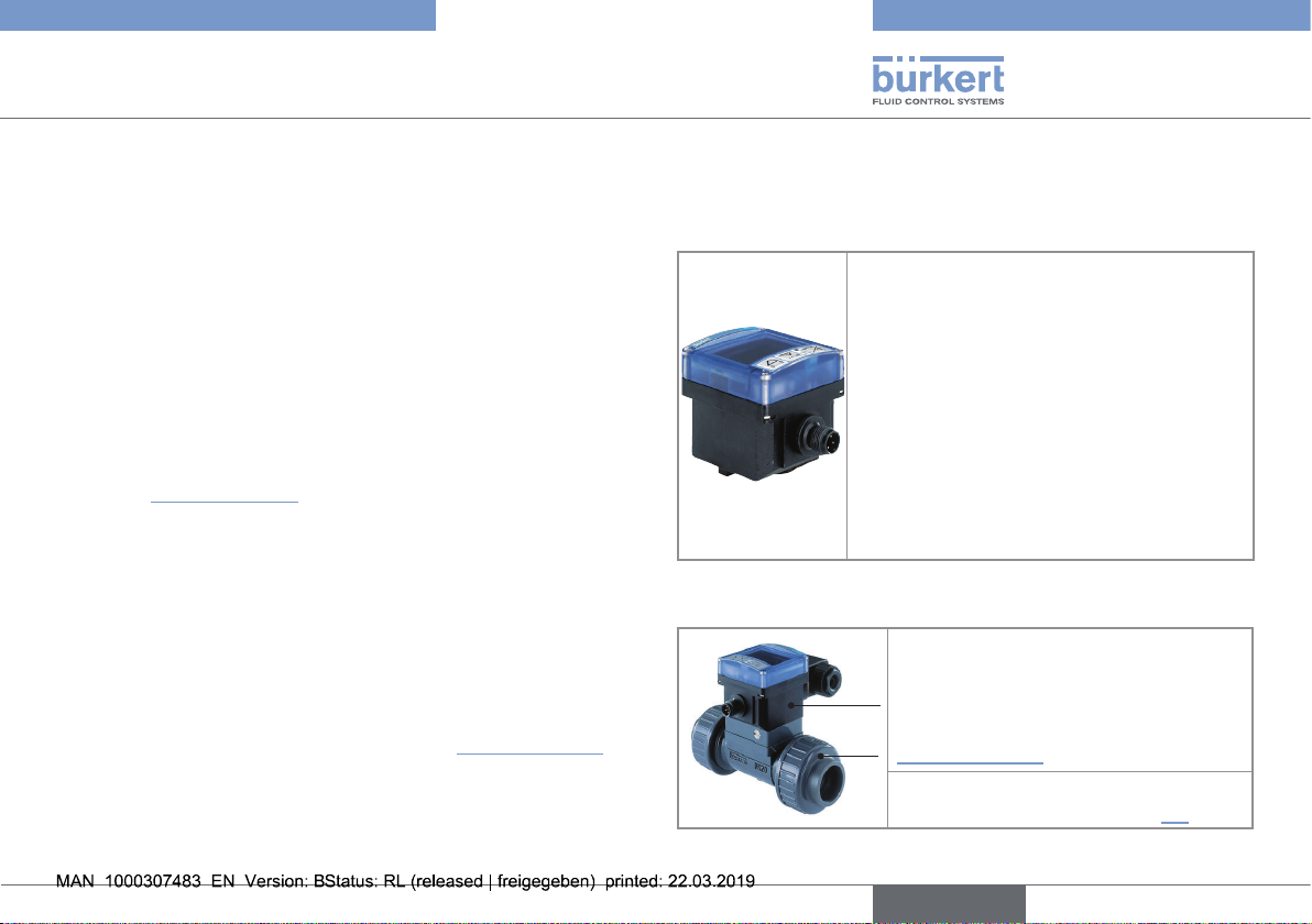
5.1. Construction of the SE32
The SE32 is a flow transmitter / flow
threshold detector with display.
In a flow transmitter version, the SE32 has:
- 1 current output and 1 relay output
or
- 1 current output
In a threshold detector version, the SE32 has
1 or 2 on/off outputs, i.e.:
- 1 or 2 transistor output(s) NPN/PNP
or
- 1 relay output
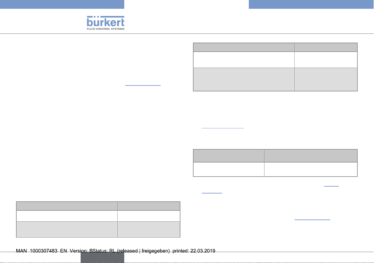
5.2. Construction of the 8032
A: Sensor-fitting type S030 including the
paddle-wheel flow sensor.
B
Operating Instructions for the S030
sensor-fitting are available under
A
www.burkert.com
B : Flow transmitter / flow threshold
detector type SE32 (see chap. 5.1).
English
9
Page 10
1
14
Type 8032 - SE32
Description
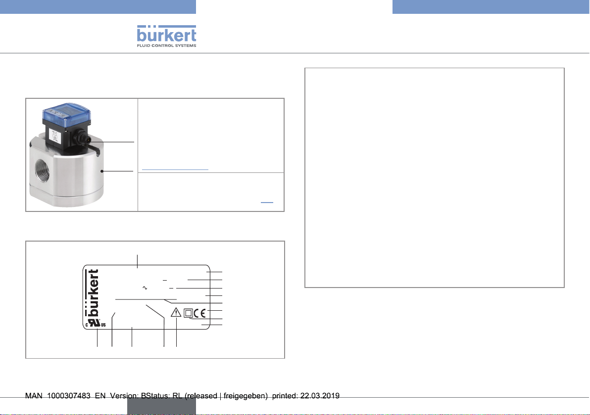
5.3. Construction of the SE32 with
sensor-fitting S077
A: Sensor-fitting type S077
including the flow sensor with oval
gears.
B
Operating Instructions for the S077
sensor-fitting are available under
A
www.burkert.com
B: Flow transmitter / flow threshold
detector type SE32 (see chap. 5.1).
5.4. Description of the rating plate
FLOW: SE32/8032 PV HALL
SUPPLY:12-36V... 80mA
REL: 30V or 60V...
PV:12-36V / 4-20mA IP65
0.3-10m/s
S-N:1110
Made in France
00560547 W45LP
12
1113
10
2
3
4
5
6
7
8
9
1. Measured process value and type of the device
2. Type of sensor
3. Power supply with maximum current consumption
4. Data of the on/off output
5. Protection class of the device
6. Data of the current output
7. Conformity marking
8. Symbol showing that the system is protected with a double
insulation or a reinforced insulation
9. Manufacturing code
10. Warning:
Before using the device, take into account the technical specifications given in the Operating Instructions
11. Measurement range of the flow rate
12. Article number
13. Serial number
14. Certification
Fig. 1 : Rating plate (example)
10
English
Page 11
Type 8032 - SE32
Technical data
6. TECHNICAL DATA
6.1. Technical data of the SE32
6.1.1. Conditions of use
Ambient temperature
(in operation)
Air humidity
Height above sea level
Operating conditions
Equipment mobility
Use
Installation category
Degree of pollution
Protection class
according to IEC/
EN 60529
1)
not evaluated by UL
–10...+60 °C
< 80%, non condensated
2000 m max.
Continuous
Fixed
Indoor and outdoor
(Protect the device against electromagnetic interference, ultraviolet rays
and, when installed outdoors, against
the effects of climatic conditions)
Category I according to UL/EN 61010-1
Degree 2 according to UL/EN 61010-1
1)
, device wired and connectors
IP65
plugged-in and tightened or sealed
6.1.2. Compliance to standards and
directives
The applied standards, which verify conformity with the EU Directives, can be found on the EU Type Examination Certificate and/or
the EU Declaration of Conformity (if applicable).
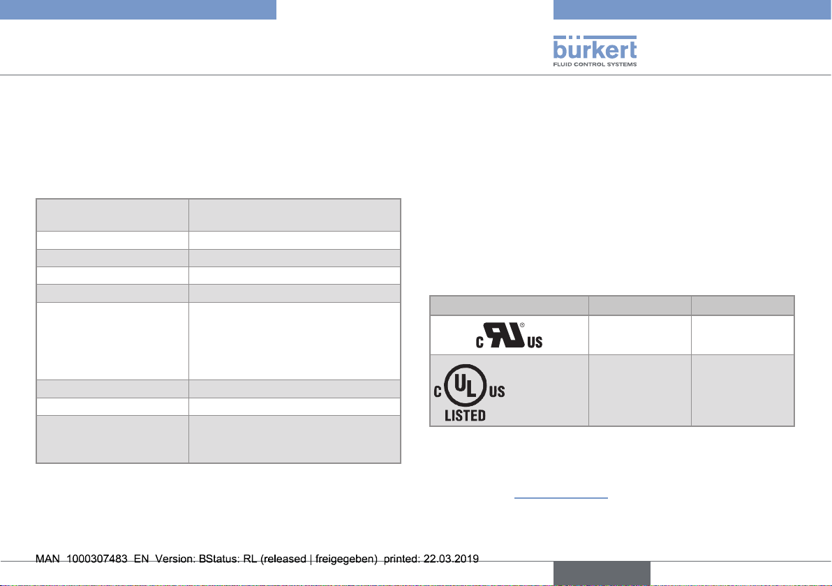
UL-Certification
Finished products with variable key PU01 or PU02 are UL-certified
products and comply also with the following standards:
• UL 61010-1
• CAN/CSA-C22.2 n°61010-1
Identification on the device Certification Variable key
UL-recognized PU01
Measuring
®
Equipment
EXXXXXX
UL-listed PU02
6.1.3. Dimensions
→ Please refer to the technical data sheet regarding the type SE32,
available at: www.burkert.com
English
11
Page 12
Type 8032 - SE32
Technical data
6.1.4. Material data
Part Material
Housing / cover PC, glass fiber reinforced
Front panel folio / Screws Polyester / stainless steel
Cable plug / M12 connector PA / PA or CuZn, nickel-plated
Rating plate Polyester
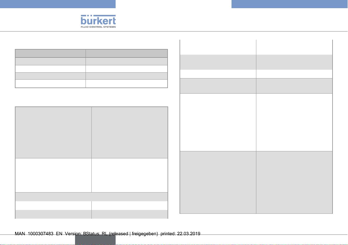
6.1.5. Electrical data
Power supply
Specifications of the power
source (not supplied)
Maximum current consumption
• version with transistor output • 50 mA
• version with 1 single relay output • 70 mA
• 12...36 V DC
• filtered and regulated
• oscillation rate: ±10 %
• Connection to main supply:
permanent (through external
SELV and through LPS
power supply)
• Limited power source according
to UL / EN 60950-1 standards
• or limited energy circuit
according to UL / EN 61010-1,
Paragraph 9.4
• version with 1 single current
output
• version with 1 relay and
1 current outputs
• Drain current (UL device) • 30...50 mA
Protection against polarity
reversal
Transistor output
Relay output (non UL device)
• single
• relay output +
4...20 mA current output
• 70 mA
• 80 mA
yes
• NPN and/or PNP,
700 mA max., operation
and thresholds can be
parametered
- NPN output: 0.2...36 V DC
- PNP output: supply voltage
• protection against short
circuits
• 3 A / 250 V AC
or 3 A / 30 V DC,
operation and thresholds can
be parametered
• 3 A / 48 V AC
or 3 A / 30 V DC,
operation and thresholds can
be parametered
12
English
Page 13
Type 8032 - SE32
Technical data
Relay output (UL device)
Danger
Danger due to the operation of the relay outputs of a UL
device in a wet location.
▶ If a UL device is used in a wet location:
- energize the relay outputs with an alternating voltage of max.
16 Vrms and 22.6 Vpeak.
- or energize the relay outputs with a direct voltage of
max. 35 V DC.
3 A / 30 V AC / 42 Vpeak
or 1 A / 60 V DC,
operation and thresholds can
be parametered
To use the relay outputs in a
wet location, observe the following safety instruction.
4...20-mA-current output
(for flow transmitter version)
• Accuracy
• Wiring
• Loop resistance
• Galvanically insulated
• 4 mA adjustment
• 20 mA adjustment
• Response time (10% up to 90%)
• ±0.5%
• 4 wires
• 1300 W at 36 V DC,
1000 W at 30 V DC,
700 W at 24 V DC,
450 W at 18 V DC,
200 W at 12 V DC
• yes
• between 3 and 5 mA
• between 18.5 and 21.5 mA
• 3 s with filter 2 (default setting)
6.2. Technical data of the 8032
6.2.1. Conditions of use
→ See conditions of use of the SE32, chap. 6.1.1, page 11.
6.2.2. Compliance to standards and
directives
The applied standards, which verify conformity with the EU Directives, can be found on the EU Type Examination Certificate and/or
the EU Declaration of Conformity (if applicable).
English
13
Page 14
• Refer to the Operating Instructions
of the related sensor-fitting (S030)
Type 8032 - SE32
Technical data
Conformity to the Pressure Equipment Directive
→ Make sure the device materials are compatible with the fluid.
→ Make sure the pipe DN is adapted for the device.
The device conforms to Article 4, Paragraph 1 of the Pressure
Equipment Directive 2014/68/EU under the following conditions:
• Device used on a pipe (PS = maximum admissible pressure;
DN = nominal diameter of the pipe)
Type of fluid Conditions
Fluid group 1, Article 4,
Paragraph 1.c.i
Fluid group 2, Article 4,
Paragraph 1.c.i
Fluid group 1, Article 4,
Paragraph 1.c.ii
Fluid group 2, Article 4,
Paragraph 1.c.ii
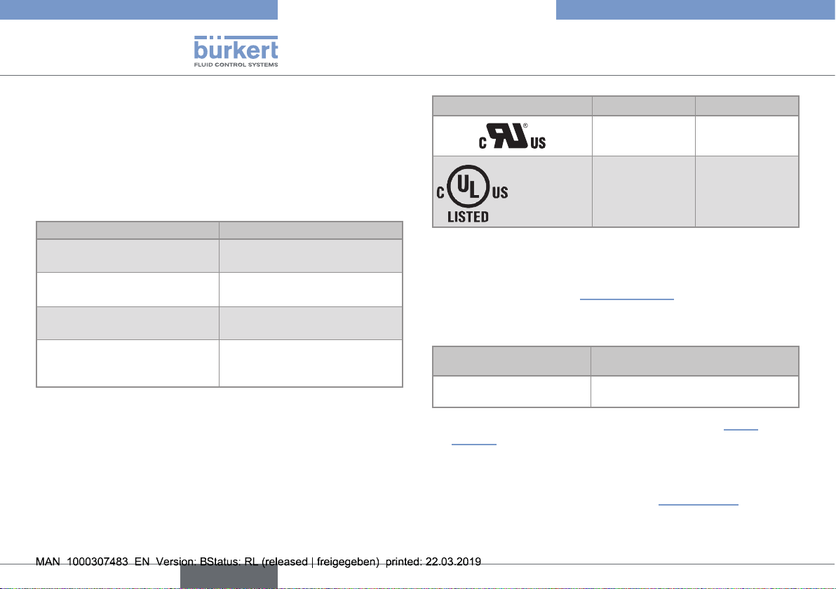
UL-Certification
Finished products with variable key PU01 or PU02 are UL-certified
products and comply also with the following standards:
• UL 61010-1
• CAN/CSA-C22.2 n°61010-1
DN≤25
DN≤32
or PSxDN≤1000
DN≤25
or PSxDN≤2000
DN≤200
or PS≤10
or PSxDN≤5000
Identification on the device Certification Variable key
UL-recognized PU01
Measuring
®
Equipment
EXXXXXX
UL-listed PU02
6.2.3. Dimensions
→ Please refer to the technical data sheets regarding the
type 8032, available at: www.burkert.com
6.2.4. Material data
Part
in contact with the medium
• Sensor-fitting
→ Also see the material data of the type SE32, chap. 6.1.4,
page 12.
Material
6.2.5. Electrical data of the 8032
→ See electrical data of the SE32, chap. 6.1.5, page 12.
14
English
Page 15
Type 8032 - SE32
Technical data
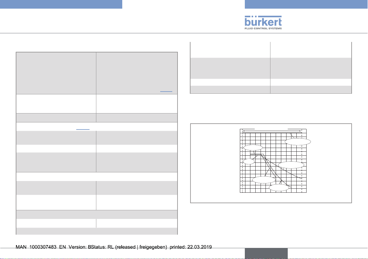
6.2.6. Fluid data
Pipe diameter
Type of fluid
Rate of solid particles
Fluid temperature (see Fig. 2)
• with S030 sensor-fitting in
PVC
• with S030 sensor-fitting in PP • 0...+80 °C
• with S030 sensor-fitting in
stainless steel, brass or PVDF
Fluid pressure
• with S030 sensor-fitting in
metal
• with S030 sensor-fitting in
plastic
Flow rate measurement
• Measuring range • 0.3...10 m/s,
• Measurement deviation
depends on the sensor-fitting
used;
The appropriate diameter of an
S030 sensor-fitting is determined using the flow/DN/fluid
velocity diagrams in chap. 7.2.1.
Refer to the Operating Instructions of the related sensor-fitting
(S030)
max. 1%
• 0...+50 °C
• –15...+100 °C
1)
• PN16
• PN10
max.
1)
max.
- with standard K-factor of
the S030 sensor-fitting
- with K-factor determined
with a Teach-In procedure
- ±3% of the measured
- ±1% of the measured
2)
value
2)
(at the value of the
value
Teach-In flow rate)
2)
• Linearity
• Repeatability
1)
not evaluated by UL
2)
These values were determined in the following reference conditions:
• ±0.5% of the full scale
2)
• ±0.4% of the measured value
medium = water, water and ambient temperatures 20°C, min. upstream and
downstream distances respected, appropriate pipe dimensions
P [bar]
16
15
14
13
12
PVC + PP
11
10
9
PVDF
8
7
6
5
4
3
2
1
0
-15 0 +20 +40 +60 +80 +100
PVC (PN10)
A
PP (PN10)
metal (PN16)
PVDF (PN10)
T [°C]
Fig. 2 : Fluid temperature / pressure dependency of the 8032,
depending on the material the S030 sensor-fitting is made of
English
15
Page 16
• Refer to the Operating Instructions
of the related sensor-fitting (S077)
Type 8032 - SE32
Technical data
6.3. Technical data of the SE32 with
S077 sensor-fitting
6.3.1. Conditions of use
→ See conditions of use of the SE32, chap. 6.1.1, page 11.
6.3.2. Compliance to standards and
directives
The applied standards, which verify conformity with the EU Directives, can be found on the EU Type Examination Certificate and/or
the EU Declaration of Conformity (if applicable).
Conformity to the Pressure Equipment Directive
→ Make sure the device materials are compatible with the fluid.
→ Make sure the pipe DN is adapted for the device.
The device conforms to Article 4, Paragraph 1 of the Pressure
Equipment Directive 2014/68/EU under the following conditions:
• Device used on a pipe (PS = maximum admissible pressure;
DN = nominal diameter of the pipe)
Type of fluid Conditions
Fluid group 1, Article 4, Paragraph 1.c.i DN≤25
Fluid group 2, Article 4, Paragraph 1.c.i
DN≤32
or PSxDN≤1000
Type of fluid Conditions
Fluid group 1, Article 4, Paragraph 1.c.ii
Fluid group 2, Article 4, Paragraph 1.c.ii
DN≤25
or PSxDN≤2000
DN≤200
or PS≤10
or PSxDN≤5000
6.3.3. Dimensions
→ Please refer to the technical data sheets regarding the
type SE32 associated with S077 sensor-fitting, available at:
www.burkert.com
6.3.4. Material data
Part
in contact with the medium
• Sensor-fitting
→ Also see the material data of the type SE32, chap. 6.1.4,
page 12.
Material
6.3.5. Electrical data
→ See electrical data of the SE32, chap. 6.1.5, page 12.
16
English
Page 17
Type 8032 - SE32
Installation and wiring
6.3.6. Fluid data
Type of fluid
Fluid temperature
• with S077 sensor-fitting in
aluminium
• with S077 sensor-fitting in
stainless steel
Max. fluid pressure
• DN15 • 55 bar
• DN25
• DN40 or DN50
• DN80
• DN100
Flow rate measurement
• Measuring range
- viscosity > 5 mPa.s - 2...1200 l/min
- viscosity < 5 mPa.s - 3...616 l/min
• Measurement deviation
- if "specific" K-factor is
used
(engraved on the
sensor-fitting)
- if "standard" K-factor is
used
• Repeatability • ±0.03% of the measured value
1)
not evaluated by UL
Refer to the Operating Instructions of the related sensor-fitting
(S077)
• –20...+80 °C
• –20...+120 °C
1)
(threaded process connection)
• 55 bar
value of the used flanges)
1)
(or in accordance to the
• 18 bar 1)
• 12 bar 1)
• 10 bar 1)
- ±0.5% of the measured
value
- ±1% of the measured value
7. INSTALLATION AND WIRING
7.1. Safety information
Danger
Risk of injury due to high pressure in the installation
▶ Stop the circulation of fluid, cut off the pressure and drain the
pipe before loosening the process connections.
Risk of injury due to high fluid temperatures.
▶ Use safety gloves to handle the device.
▶ Stop the circulation of fluid and drain the pipe before loosening
the process connections.
Risk of injury due to electrical voltage.
▶ If a 12...36 V DC powered version is installed either in a wet
environment or outdoors, all the electrical voltages must be of
max. 35 V DC.
▶ Disconnect the electrical power for all the conductors and iso-
late it before carrying out work on the system.
▶ Do not unscrew the cover of a powered device.
▶ Observe all applicable accident protection and safety regula-
tions for electrical equipment.
Risk of injury due to the nature of the fluid.
▶ Respect the prevailing regulations on accident prevention and
safety relating to the use of aggressive fluids.
English
17
Page 18

Type 8032 - SE32
Installation and wiring
Danger
Danger due to the operation of the relay outputs of a UL
device in a wet location.
▶ If a UL device is used in a wet location:
- energize the relay outputs with an alternating voltage of max.
16 Vrms and 22.6 Vpeak.
- or energize the relay outputs with a direct voltage of
max. 35 V DC.
Warning
Risk of injury due to nonconforming installation.
▶ The electrical and fluid installation can only be carried out by
qualified and skilled staff with the appropriate tools.
▶ Install appropriate safety devices (correctly rated fuse and/or
circuit-breaker).
▶ Respect the assembly instructions for the sensor-fitting used.
Risk of injury due to unintentional switch on of power supply
or uncontrolled restarting of the installation.
▶ Take appropriate measures to avoid unintentional activation of
the installation.
▶ Guarantee a set or controlled restarting of the process subse-
quent to any intervention on the device.
7.2. Fluid installation of the 8032
The 8032 is inserted into an S030 sensor-fitting mounted on the
pipe. The SE32 is assembled on the S030 sensor-fitting by a
quarter-turn rotation system:
1. Install the S030 sensor-fitting on the pipe,
2. Assemble the SE32 with the S030 sensor-fitting,
3. Finalise the installation of the 8032.
7.2.1. Install the S030 sensor-fitting on the
pipe
→ Select an S030 sensor-fitting suitable for the fluid in the pipes.
→ For thus, refer to the calculation tables page 19.
These calculation tables are used to determine the DN of the
sensor-fitting S030 appropriate to the application, according to the
fluid velocity and the flow rate.
The names of the following norms have changed in the
Operating Instructions:
• for the welding ends, norm BS 4825 is renamed
BS 4825-1;
• for the clamp connections:
- norme BS 4825 is renamed BS 4825-3
- norm DIN 32676 is renamed DIN 32676 series A
Make sure that the device runs correctly, plug in and tighten
the connectors.
18
English
Page 19

Type 8032 - SE32
Installation and wiring
l/s
100
50
10
5
1
0.5
Flow rate
0.1
0.05
0.01
0.005
l/min
5000
1000
500
100
50
20
10
5
3
2
1
0.5
0.3
0.2
m
200
100
50
20
10
0.5
0.2
0.1
0.05
0.02
0.01
3
/h
5
2
1
0.1 0.3 0.5 1 2 3 5 100.2
Flow velocity
DN 50 (DN65)*
DN 40 (DN50)*
DN 32 (DN40)*
DN 25 (DN32)*
DN 20 (DN25)*
DN 15 (DN15 / DN20)*
DN 08
DN 06
m/s
gpm
1000
500
200
100
50
20
10
5
2
Flow rate
1
0.5
0.2
0.1
0.05
0.02
0.01
Flow velocity
DN50 (DN65)*
DN40 (DN50)*
DN32 (DN40)*
DN25 (DN32)*
DN20 (DN25)*
DN15 (DN15 / DN20)*
DN08
DN06
fps
30200.3 0.5 1 2 3 5 10
* for the following fittings:
• with external threads according to SMS 1145
• with weld ends according to SMS 3008, DIN 11866 series C / BS 4825-1 / ASME BPE, DIN 11850 series 2 / DIN 11866 series A / EN 10357 series A
• with clamp connections according to SMS 3017, BS 4825-3 / ASME BPE, DIN 32676 series A
English
19
Page 20

Type 8032 - SE32
Installation and wiring
7.2.2. Assemble the SE32 with the S030
sensor-fitting
→ Install the SE32 in the S030
SE32
1
sensor-fitting.
→ Turn the SE32 by a quarter turn.
2
→ Tighten the lateral screw(s) to lock
S030
SE32 in place on the sensor-fitting.
(tightening torque max. 1 N·m,
3
i.e 0.74 lbf·ft).
Fig. 3 : Installation of the SE32 in the S030 sensor-fitting
7.2.3. Finalise the installation of the 8032
→ Wire the device and switch it on (see chap. 7.4).
→ Set the K-factor or determine it with Teach-In (see chap 9.5.2)
7.3. Fluid installation of the SE32 with
an S077 sensor-fitting
The SE32 is inserted into an S077 sensor-fitting mounted on the
pipe. The SE32 is assembled on the S077 sensor-fitting by a
quarter-turn rotation system:
1. Install the S077 sensor-fitting on the pipe,
2. Assemble the SE32 with the S077 sensor-fitting,
3. Finalise the installation.
7.3.1. Install the S077 sensor-fitting on the
pipe
→ Select an S077 sensor-fitting adapted to the viscosity of the
fluid in the pipe.
To select a sensor-fitting, refer to the technical data sheet
for the relevant sensor-fitting.
Caution
Risk of damage when installing the sensor-fitting.
▶ Follow the installation instructions given in the Operating
Instructions for the sensor-fitting.
→ Install the sensor-fitting S077 on the pipe in such a way that:
- the spindles of the oval gears are set horizontally, as shown in
Fig. 4.
- the installation instructions given in the Operating Instructions
of the sensor-fitting used are respected.
Correct Incorrect
Fig. 4 : The spindles of the oval gears must be horizontal
20
English
Page 21

S077
Type 8032 - SE32
Installation and wiring
7.3.2. Assemble the SE32 with the S077
sensor-fitting
The SE32 only detects one rotation direction of the oval
gears of a S077 sensor-fitting.
• If the combination SE32 with sensor-fitting S077 does
not run properly, once assembled and energized, do the
following:
→ remove the SE32 from the S077 sensor-fitting,
→ turn the SE32 by 180°,
→ insert the SE32 back into the S077.
1
2
Fig. 5 : Installation of the SE32 in the S077 sensor-fitting
SE32
→ Insert the SE32 in the S077
sensor-fitting.
→ Turn the SE32 by a quarter turn.
→ Tighten the lateral screws to lock
3
the SE32 in place on the S077
sensor-fitting (tightening torque
max. 1 N·m, i.e 0.74 lbf·ft).
7.3.3. Finalise the installation of the SE32
with S077 sensor-fitting
→ Wire the device and switch it on (see chap. 7.4).
→ Set the K-factor or determine it with Teach-In (see chap 9.5.2)
7.4. Wiring
Danger
Risk of injury due to electrical voltage
▶ If a 12...36 V DC powered version is installed either in a wet
environment or outdoors, all the electrical voltages must be of
max. 35 V DC.
▶ Disconnect the electrical power for all the conductors and iso-
late it before carrying out work on the system.
▶ Observe all applicable accident protection and safety regula-
tions for electrical equipment.
• Use shielded cables with a temperature limit of 80°C
minimum.
• Use a high quality electrical power supply, filtered and
regulated.
• Protect the power supply by means of a 1 A fuse and a
switch.
• Protect the power supply of each transistor by means of a
125 mA fuse.
• Protect the relays by means of a max. 3 A fuse and a
circuit breaker (depending on the process).
• Do not apply both a dangerous voltage and a safety extralow voltage to the relays.
English
21
Page 22

Type 8032 - SE32
Installation and wiring
7.4.1. Data of the cables and wires
Version Type of connector
Detector with
NPN transistor
output
Detector with
PNP transistor
output
Detector with
NPN/PNP transistor output
Detector with
relay output
Flowmeter with
relay output
Flowmeter
without relay
output
Type of connector Cable type
Female 5-pins M12 connector
(article number 917 116)
EN 175301-803 female connector
(type 2508, supplied)
EN 175301-803 female connector
(type 2508, supplied)
Female 5-pins M12 connector
(not supplied)
EN 175301-803 female connector (type 2508,
supplied) and
female 5-pin M12 connector (not supplied)
EN 175301-803 female connectors (type 2508
supplied) and
female 8-pins M12 connector (not supplied) or
female 5-pins M12 connector (not supplied)
Female 5-pin M12 connector
(not supplied)
• shielded
• external diameter of wire: 3...6.5 mm
• cross section of wires: max. 0.75 mm
Type of connector Cable type
Female 8-pins M12 connector
(article number 444 799)
Type 2508
(article number 438 811)
• shielded
• external diameter of wire: 5.9 mm
• cross section of wires: 0.25 mm
• shielded
• external diameter of wire: 6...7 mm
• cross section of wires: 0.14...0.5 mm
7.4.2. Assembling the connectors
2
4
1
2
→ Unscrew the nut [1] of the cable gland.
→ Remove the terminal block [3] from the
housing [2].
3
→ Insert the cable through the nut [1] then through
the gasket [4], through the cable gland and
finally through the housing [2].
→ Make the connections to the screw terminal
block [3] (see chap. 7.4.3, 7.4.5, 7.4.7 or 7.4.8).
→ Position the terminal block [3] in steps of 90°
then put it back into the housing [2], pulling
gently on the cable so that the wires do not
clutter the housing.
→ Tighten the nut [1] of the cable gland.
2
2
22
English
Page 23

Type 8032 - SE32
Installation and wiring
→ Place the seal [5] between the connector and
the EN 175301-803 fixed connector on the
device and then plug the type 2508 connector
5
into the fixed connector.
6
→ Insert and then tighten the screw [6] to ensure
tightness and correct electrical contact.
Fig. 6 : Assembling the female connector type 2508 (supplied)
4 3 2 1
→ Unscrew the nut [1] on the body [4].
→ Insert the cable into the nut [1], the cable
clamp [2] and the seal [3], and then into
the body [4].
5
→ Strip 20 mm of the cable.
→ Cut the central wire (earth) so that its
length is equal to 11,5 mm.
5,5
11,5
→ Expose 5.5 mm of the wires on the
20
stripped cable.
→ Insert each wire into the appropriate pin
on the terminal block [5] (see chap. 7.4.4
to 7.4.8).
→ Screw the terminal block [5] once wired
to the body [4].
→ Tighten the connector nut [1].
Fig. 7 : Assembling an female M12 connector (not supplied)
7.4.3. Wiring a version with transistor
output and EN 175301-803 male
fixed connector
Danger
Risk of injury due to electrical voltage
▶ Always plug in and tighten the connectors correctly.
The device is not tight when the EN 175301-803 fixed
connector is not wired:
→ Unscrew the nut [1] (see Fig. 6) on the female con-
nector type 2508 supplied with the device.
→ Insert the plug with article number 444 509, supplied
with the device, into the cable gland.
→ Screw the nut again.
→ Plug the sealed type 2508 connector onto the
EN 175301-803 fixed connector.
1
1
2
3
Fig. 8 : Pin assignment of the EN 175301-803 fixed connector
1. V+ (12...36 V DC)
2. Transistor output (NPN or PNP)
2
3. 0 V DC
4. Functional earth
3
English
23
Page 24

12-36 V DC
Type 8032 - SE32
Installation and wiring
Load
(solenoid valve,
for example)
+-
Power cable shield
(*)
1
V+
NPN transistor
2
output
+ -
12-36 V DC
3
0 V DC
Power supply
Fig. 9 : NPN wiring of the transistor output of a version with
EN 175301-803 fixed connector
Load
(solenoid valve,
for example)
+-
+ -
Power supply
Power cable shield
V+
1
3
0 V DC
(*)
PNP transistor
output
2
Fig. 10 : PNP wiring of the transistor output of a version with
EN 175301-803 fixed connector
(*) Functional earth
7.4.4. Wiring a version with 2 transistor
outputs and a 5-pin M12 male fixed
connector
Danger
Risk of injury due to electrical voltage
▶ Always plug in and tighten the connectors correctly.
4 3
5
1 2
→ The position of the 5-pin M12 fixed connector is adjustable:
→ Unscrew the locknut.
→ Turn the fixed connector to the desired position, by 360° max. to
prevent the cables from twisting inside the housing.
→ Tighten the locknut using a spanner, while keeping the fixed con-
nector in the desired position.
Fig. 11 : Allocation of the pins on the 5-pin M12 male fixed
connector
1. V+ (12...36 V DC)
2. NPN transistor output
3. 0 V DC
4. PNP transistor output
5. Functional earth
24
English
Page 25

12-36 V DC
(*)
Type 8032 - SE32
Installation and wiring
Pin of the M12 female cable
available as accessory equipment
Colour of the wire (signal)
(article number 438 680)
1 brown (12...36 V DC)
2 white (NPN transistor output)
3 blue (0 V DC)
4 black (PNP transistor output)
5 grey (functional earth)
When both transistor outputs are wired, they operate with
the same settings made within the OUT function.
Load 1
(wired in PNP
mode)
5
1 2
3 4
brown
blue
grey
+ -+ -
black
Load 2
(wired in NPN
mode)
white
(*)
Power cable shield
Power supply
+ -
12-36 V DC
Fig. 12 : Wiring both transistor outputs on a version with a 5-pin
M12 male fixed connector
Load
(solenoid valve,
for example)
+-
Power cable shield
white
5
1 2
3 4
brown
blue
grey
Power supply
+ -
Fig. 13 : Wiring of the NPN transistor output of a version with a
5-pin M12 male fixed connector
Load
(solenoid valve,
for example)
+-
black
5
1 2
3 4
blue
grey
brown
(*)
Power cable shield
Power supply
+ -
12-36 V DC
Fig. 14 : Wiring of the NPN transistor output of a version with a
5-pin M12 male fixed connector
(*) Functional earth
English
25
Page 26

Type 8032 - SE32
Installation and wiring
7.4.5. Wiring of the version with a single
relay output
Danger
Danger due to the operation of the relay outputs of a UL
device in a wet location.
▶ If a UL device is used in a wet location:
- energize the relay outputs with an alternating voltage of max.
16 Vrms and 22.6 Vpeak.
- or energize the relay outputs with a direct voltage of
max. 35 V DC.
Warning
Shock hazard due to the voltage at the relay terminals, which
is higher than 48 V.
▶ Before powering the device, always check that the connectors
are correctly plugged-in and tightened.
1. Common
2
1
1
3
2
3
2. Relay, normally closed (NC)
3. Relay, normally open (NO)
4. Not connected
The device is not tight when the EN 175301-803 fixed
connector is not wired:
→ Unscrew the nut [1] (see Fig. 6) on the female con-
nector type 2508 supplied with the device.
→ Insert the plug with article number 444 509, supplied
with the device, into the cable gland.
→ Screw the nut back.
→ Plug the sealed type 2508 connector onto the
EN 175301-803 fixed connector.
4 3
5
1 2
1. V+ (12...36 V DC)
2. not connected
3. 0 V DC
4. not connected
5. Functional earth
The position of the 5-pin M12 male fixed connector is adjustable:
→ Unscrew the locknut.
→ Turn the fixed connector to the desired position, by 360° max.
to prevent the cables from twisting inside the housing.
→ Tighten the locknut using a spanner, while keeping the fixed
connector in the desired position.
Fig. 16 : Pin assignment of the 5-pin M12 male fixed connector
Fig. 15 : Pin assignment on the EN 175301-803 fixed connector
26
English
Page 27

(*)
250 V AC
Type 8032 - SE32
Installation and wiring
Pin of the M12 female cable
available as accessory equipment
Colour of the wire (signal)
(article number 438 680)
1 brown (V+)
2 not connected
3 blue (0 V DC)
4 not connected
5 grey (functional earth)
(1)
250 V AC
L
N
Relay output, normally open
Load
(solenoid valve,
for example)
not connected
1
3
(NO)
2
Power cable shield
blue
Power supply
3 4
5
1 2
brown
12-36 V DC
grey
+ -
Fig. 17 : NO wiring of the relay output of a version with one 5-pin
M12 and one EN 175301-803 fixed connectors
(*)
L
N
(1)
Load
(solenoid valve,
for example)
not connected
1
3
Relay output, normally
closed (NC)
2
Power cable shield
blue
1 2
Power supply
3 4
grey
5
brown
+-
12-36 V DC
Fig. 18 : NC wiring of the relay output of a version with one 5-pin
M12 and one EN 175301-803 fixed connectors
(1) Use a voltage limiter depending on the load selected, e.g. for the solenoid
valve, an EN 175301-803 fixed connector with integrated varistor.
(*) Functional earth
English
27
Page 28

1 2
Type 8032 - SE32
Installation and wiring
7.4.6. Wiring of the version with a single
current output
4 3
5
1 2
The position of the 5-pin M12 male fixed connector is adjustable:
→ Unscrew the locknut.
→ Turn the fixed connector to the desired position, by 360° max.
to prevent the cables from twisting inside the housing.
→ Tighten the locknut using a spanner, while keeping the fixed
connector in the desired position.
Fig. 19 : Pin assignment of the 5-pin M12 male fixed connector
Pin of the M12 female cable
available as accessory equipment
(article number 438 680)
1 brown (V+)
2 white (negative 4...20 mA output)
3 blue (0 V DC)
4 black (positive 4...20 mA output)
5 grey (functional earth)
The current output can be connected in either sourcing or sinking
mode.
1. V+ (12...36 V DC)
2. Negative 4...20 mA output
3. 0 V DC
4. Positive 4...20 mA output
5. Functional earth
Colour of the wire (signal)
Power supply
12...36 V DC
+
+
(*)
-
4...20 mA input
(at external
instrument)
i
brown
grey
4
white
blue
3
5
i
i
black
shield
Fig. 20 : Wiring of the current output, in sinking mode, of a version
with a single 5-pin M12 fixed connector
Power supply
12...36 V DC
+
+
(*)
-
4...20 mA input
(at external
instrument)
i
black
4
grey
1 2
blue
i
white
3
5
shield
i
brown
Fig. 21 : Wiring of the current output, in sourcing mode, of a
version with a single 5-pin M12 male fixed connector
(*) Functional earth
28
English
Page 29

Type 8032 - SE32
Installation and wiring
7.4.7. Wiring the version with both relay
and current outputs (5-pin M12 male
fixed connector)
Danger
Danger due to the operation of the relay outputs of a UL
device in a wet location.
▶ If a UL device is used in a wet location:
- energize the relay outputs with an alternating voltage of max.
16 Vrms and 22.6 Vpeak.
- or energize the relay outputs with a direct voltage of
max. 35 V DC.
Warning
Shock hazard due to the voltage at the relay terminals, which
is higher than 48 V.
▶ Before powering the device, always check that the connectors
are correctly plugged-in and tightened.
1. Common
2
1
1
3
2
3
2. Relay, normally closed (NC)
3. Relay, normally open (NO)
4. not connected
The device is not tight when the EN 175301-803 fixed
connector is not wired:
→ Unscrew the nut [1] (see Fig. 6) on the female con-
nector type 2508 supplied with the device.
→ Insert the plug with article number 444 509, supplied
with the device, into the cable gland.
→ Screw the nut back.
→ Plug the sealed type 2508 connector onto the
EN 175301-803 fixed connector.
1: V+ (12...36 V DC)
4 3
5
1 2
2: Negative 4...20 mA output
3: 0 V DC
4: Positive 4...20 mA output
5: Functional earth
The position of the 5-pin M12 male fixed connector is adjustable:
→ Unscrew the locknut.
→ Turn the fixed connector to the desired position, by 360° max.
to prevent the cables from twisting inside the housing.
→ Tighten the locknut using a spanner, while keeping the fixed
connector in the desired position.
Fig. 23 : Pin assignment of the 5-pin M12 male fixed connector
Fig. 22 : Pin assignment on the EN 175301-803 fixed connector
English
29
Page 30

Type 8032 - SE32
Installation and wiring
The current output can be connected in either sourcing or
sinking mode.
See Fig. 26 and Fig. 27 for the related wiring charts.
7.4.8. Wiring the version with both relay
and current outputs (8-pin M12 fixed
connector)
Danger
Danger due to the operation of the relay outputs of a UL
device in a wet location.
▶ If a UL device is used in a wet location:
- energize the relay outputs with an alternating voltage of max.
16 Vrms and 22.6 Vpeak.
- or energize the relay outputs with a direct voltage of
max. 35 V DC.
Warning
Shock hazard due to the voltage at the relay terminals, which
is higher than 48 V.
▶ Before powering the device, always check that the connectors
are correctly plugged-in and tightened.
The device is not tight when the EN 175301-803 fixed
connector is not wired:
→ Unscrew the nut [1] (see Fig. 6) on the female con-
nector type 2508 supplied with the device.
→ Insert the plug with article number 444 509, supplied
with the device, into the cable gland.
→ Screw the nut back.
→ Plug the sealed type 2508 connector onto the
EN 175301-803 fixed connector.
1. Common
2
1
1
3
2
3
2. Relay, normally closed (NC)
3. Relay, normally open (NO)
4. Not connected
Fig. 24 : Pin assignment on the EN 175301-803 fixed connector
1. V+ (12...36 V DC)
5
6
4
2. Not connected
3. 0 V DC
4. Positive 4...20 mA output
8
7
1
3
2
5. Not connected
6. Negative 4...20 mA output
7. Not connected
8. Functional earth
Fig. 25 : Allocation of the pins on the M12, 8-pin fixed connector
30
English
Page 31

1 2
Type 8032 - SE32
Installation and wiring
Pin of the 8-pin M12 female cable
Colour of the wire (signal)
available as an accessory equipment
(article number 444 800)
1 white (12...36 V DC)
2 not connected
3 green (0 V DC)
4 yellow (positive 4...20 mA output)
5 not connected
6 pink (negative 4...20 mA output)
7 not connected
8 grey (functional earth)
The current output can be connected in either sourcing or sinking mode.
Power supply
12-36 V DC
+
(*)
+
-
4...20 mA input
(at external
instrument)
i
i
green
shield
white
6
7
1 2
yellowpink
grey
i
5
4
3
8
Fig. 26 : Wiring of the current output, in sinking mode, of a version
with an 8-pin M12 fixed connector
Power supply
12-36 V DC
+
(*)
+
-
4...20 mA input
(at external
instrument)
i
i
grey
white
pink
i
5
6
7
yellow
4
green
3
8
shield
Fig. 27 : Wiring of the current output, in sourcing mode, of a
version with an 8-pin M12 fixed connector
250 V AC
L
N
(1)
Relay output, normally open
(NO)
Load (solenoid
valve, for example)
not connected
1
3
Power supply (2)
6
7
2
1 2
white
12-36 V DC
green
5
4
3
8
grey
(*)
+ -
Power cable
shield
Fig. 28 : NO wiring of the relay output of a version with an 8-pin
M12 fixed connector
English
31
Page 32

250 V AC
Type 8032 - SE32
Installation and wiring
green
5
4
3
8
grey
(*)
+ -
Power cable
shield
L
N
(1)
Relay output, normally
closed (NC)
Load (solenoid valve,
for example)
not connected
1
3
Power supply (2)
6
7
2
1 2
white
12-36 V DC
Fig. 29 : NC wiring of the relay output of a version with an 8-pin
M12 fixed connector
(*) Functional earth
(1) Use a voltage limiter depending on the load selected, e.g. for the solenoid
valve, an EN 175301-803 fixed connector with integrated varistor.
(2) If the current output is needed, wire the 8-pin M12 connector acc. to
Fig. 26 if the current output is wired in sinking mode, or acc. to Fig. 27 if the
current ouput is wired in sourcing mode.
8. COMMISSIONING
8.1. Safety information
Warning
Danger due to nonconforming commissioning.
Nonconforming commissioning could lead to injuries and damage
the device and its surroundings.
▶ Before commissioning, make sure that the staff in charge have
read and fully understood the contents of the manual.
▶ In particular, observe the safety recommendations and intended use.
▶ The device/installation must only be commissioned by suitably
trained staff.
▶ Before commissioning the device, enter the K-factor of the fit-
ting used. See chap. 9.4 and 9.5.
note
Risk of damage to the device due to the environment
▶ Protect this device against electromagnetic interference,
ultraviolet rays and, when installed outdoors, the effects of the
climatic conditions.
32
English
Page 33

Type 8032 - SE32
Adjustment and functions
• When the device is switched on and the cover is open,
protection against electric shock is no longer guaranteed.
• Check the chemical compatibility between the fluid to
be measured and the materials from which the device is
made exposed to it.
9. ADJUSTMENT AND FUNCTIONS
9.1. Safety information
Danger
Risk of injury due to electrical voltage
▶ If a 12...36 V DC powered version is installed either in a wet
environment or outdoors, all the electrical voltages must be of
max. 35 V DC.
▶ Observe all applicable accident protection and safety guidelines
for electrical equipment.
Warning
Risk of injury due to nonconforming adjustment.
Nonconforming adjustment could lead to injuries and damage the
device and its surroundings.
▶ The operators in charge of adjustment must have read and
understood the contents of this manual.
▶ In particular, observe the safety recommendations and intended
use.
▶ The device/installation must only be adjusted by suitably trained
staff.
English
33
Page 34

Type 8032 - SE32
Adjustment and functions
9.2. Operating levels
All settings may influence the correct running of the
process.
• Note the values of the parameters set in the table at
chap. 9.8.
The device has 2 operating levels:
• the Process level,
• the Configuration level.
The Configuration level comprises the Parameters and Test menus.
Operating level Functions
Process • To read out:
- the measured flow rate
- the switching thresholds
- the value of the 4...20 mA output (flowmeter only)
• To access the Parameters and Test menus
of the Configuration level
Operating level Functions
Configuration Parameters menu
Configuration Test menu
• To make the settings needed for operation:
- flow rate unit,
- transistor or relay output,
- filter,
- bar graph,
- K-factor,
- 4...20-mA-current output (flowmeter only).
• To make the following additional settings:
• backlighting,
• access code to the Parameters and Test
menus.
• To test the configuration made in the
Parameters menu with entering of a theoretical value.
• To read the frequency of the measured
signal.
• To adjust the 4...20 mA output.
34
English
Page 35

Type 8032 - SE32
Adjustment and functions
9.3. Description of the display and
the operating keys
The display is used to:
• read the value of certain parameters such as the measured flow
rate;
• parameterize the device by means of 3 keys;
• read the configuration of the device;
• get notification of some events.
• To change the value (0...9)
0......9
Back key
Next key
ENTER
Confirm key
of the selected digit;
• To go back to the previous
function.
• To select the digit at the
left;
• To go to the next function.
• To confirm the function
displayed;
• To confirm the parameters
set.
Bar graph running in each
mode, except during a
Teach-In procedure.
O
U
T
Shows the status of the on/
off output (red LED).
Shows if the relay is open or
closed.
Means that the access to
the Parameters and Test
menus is protected through
a code.
Fig. 30 : Description of the keys and icons
9.4. Process level
The use and setting of the access code to the Parameters
and Test menus are defined within the Parameters menu.
Display displays...
Display A ...the measured flow rate
Display B (only flowmeters) ...the value of the 4...20 mA output.
Display C ...the value of the low switching
threshold (
Display D ...the value of the high switching
threshold (
O LO).
O HI).
English
35
Page 36

Display A
Display B
Display C
Display D
0......9
Process level
1
0.615
l/s
12.56
MA
0.200
OLO
1.000
OHI
(by default)
Press the keys simultaneously
0......9
0......9
+
more than 5 s
ENTER
+
> 5 s
ENTER
+
> 5 s
> 5 s
+
ENTER
OFF
Status of
function
CODE?
Status of
function CODE?
OFF
(by default)
ON
ON
0000
0......9
0000
0......9
CODE
CODE
Type 8032 - SE32
Adjustment and functions
ENTER
ENTER
Code
OK?
Code
OK?
2
3
access to the Parameters menu (see
chap. 9.5)
access to the Test
menu (see chap. 9.6)
36
English
Page 37

Type 8032 - SE32
Adjustment and functions
9.5. Configuration level - Parameters menu
All settings may influence the correct running of the process.
→ Note the values of the parameters set in the table at chap. 9.8.
Function Description of the function
UNIT (see chap. 9.5.1) To select the unit of the flow rate.
KFAC (see chap. 9.5.2) To enter the K-factor of the sensor-fitting used or have it determined. The K-factor is specific to each sensor-
fitting. It is used by the device to convert the measured signal into a flow rate.
OUT (see chap. 9.5.3) • To select:
- the operation of the transistor or relay output (Hysteresis or Window);
- whether the operation is inverted or not.
• To set:
- the high (
- the time delay before switching in seconds (
mA (see chap. 9.5.4) To set the flow rate range associated to the 4...20 mA output.
FILT (see chap. 9.5.5) • To choose the filter of the displayed flow rate.
Filter 0 means that flow rate variations are displayed.
Filter 9 means that flow rate variations are attenuated to the maximum.
BRGR (see chap. 9.5.6)
BKLG (see chap. 9.5.7) To deactivate the backlighting of the display, or adjust its intensity and set the time-out after which it goes off.
CODE (see chap. 9.5.8) To activate the use of the access code to the Parameters and Test menus. By default, the access code is not
END (see chap. 9.5.9) To go back to the Process level by saving or not the settings made.
To enter the flow rate range, minimum (
requested.
O HI) and low (O LO ) switching thresholds;
DEL).
BG LO) and maximum (B G HI) values, associated to the bar graph.
English
37
Page 38

9.5.1. Selecting the unit of the flow rate
Warning
If the flow rate unit is modified, also modify the transistor or relay
switching thresholds (function OUT), the threshold values of the
bar graph (function BRGR) and the flow rate range associated to
the current output (function mA).
2
ENTER
UNIT
0......9
GA/H
To function KFAC
→ Select the desired unit of the flow rate.
L/S
UNIT
ENTER
.
.
.
ENTER
2
Refer to chap. 9.4 to access
the Parameters menu.
Type 8032 - SE32
Adjustment and functions
38
English
Page 39

Type 8032 - SE32
Adjustment and functions
9.5.2. Entering the K-factor or having it determined by Teach-In
During the whole Teach-In procedure, the outputs are frozen to the status they had at the start of the Teach-In.
• Entering the K-factor of the sensor-fitting used:
KFAC
To function OUT
* to move the decimal point, simultaneously press keys
ENTER
0......9
NO
TEAC
YES
TEAC
ENTER
ENTER
TEAC
49.03
KFAC
0......9
ENTER
ENTER
*
200.0
0......9
0......9
ENTER
VOL
*
and
49.03
KFAC
ENTER
→ select "NO TEAC",
→ press key "ENTER",
→ In the KFAC parameter, enter the K-factor of the
sensor-fitting used, in pulse/litre (value between
0.001 and 9999). Find the K-factor within the Operating Instructions of the sensor-fitting.
• Determining the K-factor by means of a Teach-In
procedure:
→ install the device in series with a valve, for instance,
then
→ fill a tank with x litres capacity (200 litres for
example).
→ select "YES TEAC",
→ press key "ENTER",
→ open the valve: message "TEAC" blinks.
→ when the tank if full, press again key "ENTER".
→ enter the volume of liquid that has passed through
the circuit (in the unit displayed alternately with the
message "VOL"): the device calculates the K-factor
and displays it.
English
39
Page 40

9.5.3. Configuring the relay or transistor output
Type 8032 - SE32
Adjustment and functions
ENTER
OUT
To function "mA"
0......9
MODE
MODE
ENTER
ENTER
0.200
OLO
0......9
*
no
OHI>
OLO
yes
1.000
0......9
0......9
01
DEL
* to move the decimal
point, simultaneously
press keys
0......9
and
ENTER ENTER
OHI
0......9
*
NO
ENTER ENTER
inv
ENTER
YES
inv
40
English
Page 41

OLO OHI
OLO OHI
OLO OHI
Type 8032 - SE32
Adjustment and functions
Hysteresis operation
The change of state is done when a threshold is detected
(increasing flow rate:high threshold (OHI) to be detected,
decreasing flow rate: low threshold (OLO) to be detected).
Contact
ON
OFF
Not inverted
Flow
rate
Contact
ON
OFF
Inverted
Flow
rate
Fig. 31 : Hysteresis operation of the transistor output
Window operation
The change of state is done whenever one of the thresholds is
detected.
ON
OFF
Not invertedContact
OLO OHI
Flow
rate
Contact
ON
OFF
Inverted
Flow
rate
Fig. 32 : Window operation of the transistor output
The time delay (DEL) is valid for both output thresholds. switching
is only done if one of the thresholds (OHI - OLO) is exceeded for a
duration longer than this time delay.
Flow rate
OHI
OLO
2 s
Hysteresis operation
DEL = 0 s
DEL = 2 s
Window operation
DEL = 0 s
DEL = 2 s
Not inverted
Inverted
Not inverted
Inverted
Not inverted
Inverted
Not inverted
Inverted
OUT
ON
OFF
ON
OFF
ON
OFF
ON
OFF
ON
OFF
ON
OFF
ON
OFF
ON
OFF
2 s
2 s
t
Fig. 33 : Examples for the behaviour of the transistor or relay output
of a 8032 or a SE32 with S077, depending on the flow
rate and the operation chosen.
English
41
Page 42

ENTER
0......9
*
0......9
*
ENTER ENTER
Type 8032 - SE32
Adjustment and functions
9.5.4. Setting the flow rate range
associated to the 4...20 mA output
The 4...20 mA output provides an electrical current, the value of
which reflects the flow rate measured by the device.
• The signal may be inverted, i.e. the flow rate value associated
to the 20-mA-current is lower than the one associated to the
4-mA-current.
• The current output gives a 22-mA-current when the device shows
an operating error.
mA
20
4
20 180
Fig. 34 : Example of relation between the measuring range and the
current output
MA
To function "FILT"
→ Enter the flow rate values, in the unit that has been chosen in the
0.200
4ma
1.000
UNIT parameter, related to the 4...20-mA-current range.
20ma
l/min
* to move the
decimal point,
simultaneously
press keys
0......9
and
9.5.5. Choosing the filter of the flow rate
FILT
ENTER
ENTER
2
FILT
0......9
To function "BRGR"
The "Filter" function is used to attenuate the display and 4...20 mA
output, if any, fluctuations when the flow rate varies in the process.
Ten attenuation levels, from 0 (means no attenuation) to 9 (maximum
attenuation of the fluctuations) are available.
42
English
Page 43

ENTER
0......9
*
0......9
*
ENTER ENTER
Type 8032 - SE32
Adjustment and functions
Tab. 1 : Response times of the current output and the display
depending on the filter chosen
Filter N° Response time (10% up to 90%)
0 300 ms
1 1,5 s
2 3 s
3 (by default) 5 s
4 7 s
5 11 s
6 20 s
7 38 s
8 100 s
9 200 s
9.5.6. Entering the flow rate range related
to the bar graph
BRGR
To function "BKLG"
* to move the decimal point, simultaneously press keys
0.200
BGLO
Set the min. and max. flow rate values, in the unit chosen within the
"UNIT" function, related to the bar graph:
• BGLO is related to the flow rate value for which all the bar graph
segments are out.
• BGHI is related to the flow rate value for which all the bar graph
segments are on.
1.000
BGHI
0......9
and
English
43
Page 44

Type 8032 - SE32
Adjustment and functions
9.5.7. Adjusting the brightness of the
backlight or deactivating the
backlight
BKLG
To function "CODE"
ENTER
0......9 0......9
• Function "BKLG": to deactivate the backlight (choice "0") or to
choose its intensity (choice "1" to "9").
• Function "BDEL": to have the backlight permanently activated
(choice "00") or have it on for a constant duration (between "01"
and "99" seconds) after a key press.
ENTER ENTER
5
BKLG
0
BDEL
9.5.8. Activating and defining the access
code to the Configuration level
CODE
ENTER
0......9
ON
CODE
OFF
ENTER
0000
0......9
CODE
ENTER
CODE
To function "END"
• Function "CODE ON": the access code to the Parameters and
Test menus is required. Enter a 4-digit code.
• Function "CODE OFF": the access code to the Parameters and
Test menus is not required.
44
English
Page 45

Type 8032 - SE32
Adjustment and functions
9.5.9. Saving the modified parameters
END
ENTER
0......9
NO
save
YES
save
ENTER
ENTER
Back to the Process
1
level
Back to the Process
1
level
• Function "SAVE NO": the changes made within the Parameters
menu are not saved. Is only displayed if any parameter has been
changed.
• Function "SAVE YES": the changes made within the Parameters
menu are saved. Is only displayed if any parameter has been
changed.
English
45
Page 46

9.6. Configuration level - Test menu
Type 8032 - SE32
Adjustment and functions
3
FREQ
ENTER ENTER
123.4
HZ
ENTER ENTER
SIM
0......9
MA
see chap. 9.6.1
ENTER
END
* to move the decimal point, simultaneously press keys
0.600
SIM
0......9
*
1
1
and 3: see chap. 9.4, Process level
0......9
FREQ To read the frequency of the measured signal.
SIM To test the switching thresholds set for the transistor
output or the relay output and/or the conversion of the
flow rate into mA, by entering a flow rate value.
MA To adjust the 4...20 mA output.
END To go back to the Process level and display the flow
rate measured.
and
46
English
Page 47

Type 8032 - SE32
Adjustment and functions
9.6.1. Adjusting the 4...20 mA output
yes
ENTER ENTER
MA
3.95
OFFS
0......9
*
To the function "END" of the Test menu
20.50
span
0......9
ENTER
YES
MA
0......9
NO
*
MA
• When the function "OFFS" is displayed, the device gives a 4-mA-current.
→ Measure the current given on the 4...20 mA output using a multimeter.
→ Enter this value in the function
OFFS . The permitted offset range is 3 to 5 mA.
→ Press ENTER to confirm.
• When the function "SPAN" is displayed, the device gives a 20-mA-current.
→ Measure the current given on the 4...20 mA output using a multimeter.
→ Enter this value in the function
→ Confirm or do not confirm the values entered by choosing "
SPAN . The permitted span range is 18.5...21.5 mA.
YES MA" or "NO MA". When the message "ERR11" is displayed, at least one of the
values entered is outside the permitted range: see chap. 10.3.
ENTER
ENTER
ERR 11 ?
no
English
* to move the decimal point, simultane-
ously press keys
0......9
and
47
Page 48

Type 8032 - SE32
Adjustment and functions
9.7. Default settings
At first power-up of the device, the configuration of the 8032 or the SE32 with S077 is the following:
Flow rate
unit
UNIT KFAC Operation OLO
l/s 1 imp./l Hysteresis, inverted 0
1)
In the unit set within the UNIT function (l/s, by default).
2)
By default, the access code is not requested (CODE=OFF).
K-factor Relay or transistor output Current
output
OHI
threshold
threshold
1)
0 1) 0 s 0 1) 100
DEL 4 mA 20 mA FILTER BG LO BG HI BKLG BDEL CODE
Filter Bar graph Backlighting Code
1)
2 0 1) 0 1) 5 0 s 0000 2)
9.8. Your settings for the 8032 / the SE32 with S077
Flow rate
K-factor Relay or transistor output Current
unit
UNIT KFAC Operation OLO
threshold
ON
OFF
1)
Hysteresis operation:
48
OLO OHI
English
OHI
threshold
Filter Bar graph Backlighting Code
output
DEL 4 mA 20 mA FILTER BG LO BG HI BKLG BDEL CODE
ON
OFF
2)
Window operation:
OLO OHI
Page 49

Type 8032 - SE32
Maintenance and troubleshooting
10. MAINTENANCE AND
TROUBLESHOOTING
10.1. Safety information
Danger
Risk of injury due to high pressure in the installation
▶ Stop the circulation of fluid, cut off the pressure and drain the
pipe before loosening the process connections.
Risk of injury due to electrical voltage
▶ Shut down the electrical power source of all the conductors and
isolate it before carrying out work on the system.
▶ Observe all applicable accident protection and safety guidelines
for electrical equipment.
Risk of injury due to high fluid temperatures
▶ Use safety gloves to handle the device.
▶ Stop the circulation of fluid and drain the pipe before loosening
the process connections.
▶ Keep all easily flammable material and fluid away from the
device.
Risk of injury due to the nature of the fluid
▶ Respect the regulations on accident prevention and safety relat-
ing to the use of aggressive fluids.
Warning
Risk of injury due to non-conforming maintenance
▶ Maintenance must only be carried out by qualified and skilled
staff with the appropriate tools.
▶ Guarantee a defined or controlled restarting of the process
subsequent to any intervention on the device.
10.2. Maintenance and cleaning
note
The device may be damaged by the cleaning product.
▶ Clean the device with a cloth slightly dampened with water or a
cleaning liquid compatible with the materials the device is made of.
Please feel free to contact your Bürkert supplier for any additional
information.
English
49
Page 50

10.3. If you encounter problems
Type 8032 - SE32
Maintenance and troubleshooting
Message
displayed
ERR 2 22 mA The Parameters menu cannot be accessed.
ERR 11 - The span and/or offset values entered during
4...20 mA output,
if present
Meaning Recommended actio
Read fault of the menu: the process is not stopped.
adjustment of the 4...20 mA output are out of range:
offset < 3 mA or > 5 mA
and/or span <18.5 mA or > 21.5 mA
→ Press the ENTER key to acknowledge the
message.
→ If the failure occurs regularly, contact your
retailer.
→ Press the ENTER key to go back to the Test
menu.
The device operates with the previous adjustment
values.
50
English
Page 51

Type 8032 - SE32
Spare parts and accessories
11. SPARE PARTS AND
ACCESSORIES
Caution
Risk of injury and/or damage by the use of incorrect parts
Incorrect accessories and unsuitable spare parts may cause
injuries and damage the device and the surrounding area.
▶ Use only original accessories and original spare parts from
Bürkert.
Spare part Article number
1)
Complete unit
outputs
Complete unit
Complete unit
Complete unit
current outputs
1)
Complete unit = cover, display and electronic board
with NPN and PNP transistor
1)
with a single relay output
1)
with a single current output
1)
with both relay and 4...20 mA
563 103
563 104
563 105
563 106
Accessory Article number
5-pin M12 female connector, to be wired
5-pin M12 female connector, moulded on
917 116
438 680
shielded cable (2 m)
EN175301-803 female connector
438 811
(type 2508) with cable gland
Plug for the cable gland of the type 2508
444 509
female connector
EN175301-803 female connector
162 673
(type 2509) with NPT ½" reduction
8-pin M12 female connector, to be wired
8-pin M12 female connector, moulded on
444 799
444 800
shielded cable (2 m)
English
51
Page 52

Type 8032 - SE32
Packaging, Transport
12. PACKAGING, TRANSPORT
note
Damage due to transport
Transport may damage an insufficiently protected device.
▶ Transport the device in shock-resistant packaging and away
from humidity and dirt.
▶ Avoid the effects of heat and cold, which could cause the stor-
age temperature range to be exceeded.
▶ Protect the electrical interfaces using protective plugs.
13. STORAGE
note
Poor storage can damage the device.
▶ Store the device in a dry place away from dust.
▶ Ambient storage temperature: –10...+60°C.
14. DISPOSAL OF THE DEVICE
→ Dispose of the device and its packaging in an environmentally-
friendly way.
note
Damage to the environment caused by parts contaminated by
the fluid.
▶ Comply with the national and/or local regulations which concern
the area of waste disposal.
52
English
Page 53

Page 54

www.burkert.com
 Loading...