

Page 1
Instruction manual
00553593 - 1107/0_Original_FR
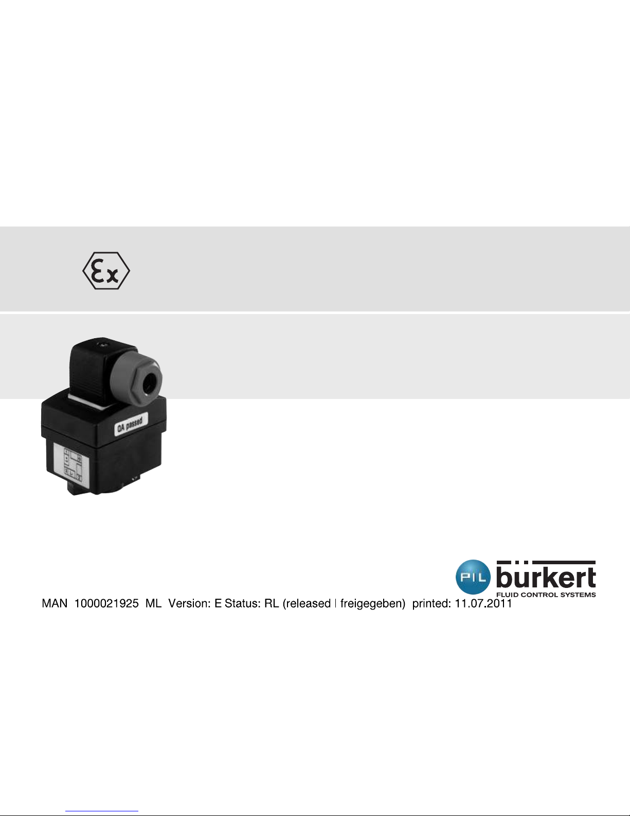
FLOW SENSOR FOR POTENTIALLY EXPLOSIVE
ATMOSPHERES
II 1 G/D
I M 1
© Bürkert 2004-2011 Subject to technical change without notice
Page 2

ENGLISH
ENGLISH
Flow sensor SE30 Ex
1. DECLARATION OF CONFORMITY ...................................................................................................................4
2. SAFETY INSTRUCTIONS – NOTICE OF ATEX INSTRUCTIONS .....................................................6
2.1. Use .......................................................................................................................................................................6
2.2. Warranty and liability ..................................................................................................................................9
2.3. Precautions during installation and commissioning ..............................................................10
2.4. Traceability ....................................................................................................................................................11
3. DESCRIPTION .........................................................................................................................................................12
3.1. Construction and measurement principle ...................................................................................12
3.2. Ordering table for flow sensors SE30 Ex ....................................................................................13
3.3. Ordering table for spare parts and accessories ...................................................................... 13
3.4. Ordering table for intrinsic safety barriers ..................................................................................14
3.5. Description of the nameplate SE30 Ex .........................................................................................15
4. TECHNICAL DATA .................................................................................................................................................18
4.1. General data ................................................................................................................................................18
4.2. Dimensions (mm) and materials ......................................................................................................20
4.3. Electrical data .............................................................................................................................................21
Page 3

3
ENGLISH
ENGLISH
SE30 Ex
4.4. Electrical connections ............................................................................................................................21
4.5. Environment .................................................................................................................................................22
5. INSTALLATION AND WIRING ..........................................................................................................................24
5.1. General recommendations ..................................................................................................................24
5.2. Assembling and mounting on the pipe .........................................................................................24
5.3. Electrical connection ...............................................................................................................................26
5.3.1. Assembling the female connector type 2508 ................................................................. 26
5.3.2. Wiring of the SE30 Ex, marking II 1 G/D or 1 M1 (with NAMUR intrinsic safety
barrier) ............................................................................................................................................. 27
6. ANNEX ........................................................................................................................................................................ 30
6.1. Possible connections with the SE30 Ex flow sensor ............................................................ 30
6.2. Connection example with the SE30 Ex and the externally powered intrinsic
safety barrier ...............................................................................................................................................31
6.3. Connection example with the SE30 Ex and the intrinsic safety barrier, 24
VDC, powered through the transmitter .........................................................................................32
Page 4
ENGLISH
ENGLISH
Flow sensor SE30 Ex
1. Declaration of conformity
We, Burkert, declare as manufacturer that the following product:
ELECTRONIC FLOWMETER
Type SE30 Ex NAMUR
with the marking II 1 G/D or I M1, meets the specifications:
• of EC Directive 94/9/EC concerning equipment intended for use in
explosive atmospheres. For the evaluation the following standards
have been taken into account:
- EN 60079-0 (2006)
- EN 60079-11 (2007)
- EN 61241-0 (2004)
- EN 61241-11 (2007)
• of EEC Directive 2004/108/EEC on electromagnetic compatibility. For
the evaluation the following standards have been taken into account:
- Emission according to EN 61000-6-3 (2007)
- Immunity according to EN 61000-6-2 (2005)
Page 5
5
ENGLISH
ENGLISH
SE30 Ex
The EC type certification LCIE 04 ATEX 6070 X was prepared by LCIE
(Laboratoire Central des Industries Electriques, 33 avenue du Gal
Leclerc, BP 8, F-92266 Fontenay-aux-Roses).
Provided the use is conform to their intended purpose and/or provided
installation is conform to the standards in force and/or to the recommendations of the manufacturer and the special conditions for safe use
specified in the EC type certification. See chapter 2 within this manual.
Notification of assessment of the quality system N° PTB 98 ATEX
Q008-2 was prepared by the PTB (Physikalisch-Technische Bundesanstalt, Bundesallee 100, D-38116 BRAUNSCHWEIG).
Triembach-au-Val, February 18th 2010 Quality insurance
Bürkert S.A.S Bruno Thouvenin
Rue du Giessen
F-67220 Triembach-au-Val
Page 6
ENGLISH
ENGLISH
2. Safety instructions – notice of ATEX instructions
Comply with the safety instructions, marked by the symbol
opposite, and all the instructions contained in this manual.
Adhere to the specific ATEX recommendations marked by the
symbol opposite.
2.1. Use
The SE30 Ex sensor is intended for measuring the flow rate in neutral
or slightly aggressive liquids that have no solid particles in the following
explosive areas:
• areas 0,1 or 2 and areas 20, 21, 22 category II 1G/D appliance
• firedamp mines category I M1 appliance
Model SE30 Ex NAMUR with order code 552901, for potentially
explosive areas of gas (0, 1 and 2) and/or dust (20, 21 and 22)
• Helps with understanding the marking and with installation:
CE 0102
II 1 GD
Ex ia IIC T6
Ex iaD 20 IP6X T80°C
T ambiant: 0°C ≤ Ta ≤ 60°C
LCIE 04 ATEX 6070 X
Page 7
7
ENGLISH
ENGLISH
SE30 Ex
• Special conditions for safe use:
- The equipment is an appliance that is intrinsically safe.
- It may be installed in potentially explosive atmospheres: areas 0, 1
or 2 and areas 20, 21 or 22.
- The connector only has to be connected to an appliance that has the
intrinsic safety certification. Said connections must be compatible
as regards intrinsic safety and comply with the following parameters.
- Ambient temperature for use: from 0 °C to +60 °C
• Special parameters of relevant protection method/s:
Ui ≤ 15V, Ii ≤ 50 mA, Pi ≤ 188 mW, Ci ≤ 1,2 nF, Li ≅ 0
• Mechanical assembly and fluid connections that are compatible with
said marking and said use:
Use only brass, stainless steel, aluminium or PVDF fittings.
If the fitting is fitted with a PP paddle-wheel, ensure there is no risk
of explosion within the pipe: the fluidics must be within the safe
area.
• Any other fittings are prohibited in explosive areas.
Page 8

ENGLISH
ENGLISH
Flow sensor SE30 Ex
Model SE30 Ex NAMUR with order code 553455, for firedamp mines
• Helps with understanding the marking and with installation
CE 0102
I M1
Ex ia I T80°C
T ambiant: 0°C ≤ Ta ≤ 60°C
LCIE 04 ATEX 6070 X
• Special conditions for safe use:
- The equipment is an appliance that is intrinsically safe for firedamp
mines.
- It may be installed in potentially explosive atmospheres: mine.
- The connector only has to be connected to an appliance that has
the intrinsic safety certification. Said connections must be compatible as regards intrinsic safety and comply with the following parameters.
- Ambient temperature for use: from 0 °C to +60 °C
• Special parameters of relevant protection method/s:
Ui ≤ 15V, Ii ≤ 50 mA, Pi ≤ 188 mW, Ci ≤ 1,2 nF, Li ≅ 0
Page 9
9
ENGLISH
ENGLISH
SE30 Ex
• Mechanical assembly and fluid connections that are compatible with
said marking and said use:
- Use brass or stainless steel fittings only, with a PVDF paddle-wheel
for an S030 fitting.
- Any other fitting is prohibited.
- The appliance must be protected from mechanical damage. Mechanical protection with order code 553519 should be used.
2.2. Warranty and liability
During the warranty period and outside said period the Bürkert company
alone is authorised to carry out repairs or alterations to any of its
products that has been awarded EC type examination certification.
Bürkert disclaims its liability in the event of non-compliance with this
clause.
The assembly work must be carried out by qualified personnel. In
the event of problems with installation or commissioning, please
contact your Bürkert supplier as soon as possible.
Page 10
ENGLISH
ENGLISH
Flow sensor SE30 Ex
2.3. Precautions during installation and
commissioning
• Always ensure that the appliance that is in contact with the fluid to be
measured is chemically compatible.
• Similarly, when the equipment is cleaned please use products that
are chemically compatible with the materials of which the appliance is
made.
• Protect the device from electromagnetic perturbations, ultraviolet
radiations and, when installed outside, from the effects of climatic
conditions.
Said appliance must be installed in accordance with the provisions
of standard EN 60079-14: Electric appliance for potentially explosive
atmospheres.
Part 14: electrical installations in dangerous sites (other than
mines).
When the sensor is disassembled from the pipe, take all the precautions associated with the process.
Page 11

11
ENGLISH
ENGLISH
SE30 Ex
2.4. Traceability
The SE30 Ex products are identified by an individual batch number which
allows them to be traced. This number (5 figure), plus the year, is
inscribed on a nameplate bearing the complete reference for the
equipment.
This product is an appliance for potentially explosive atmospheres. In this
regard and in compliance with the EC ATEX 94/9 Directive, provisions
must be made to ensure ascending and descending traceability.
Our ATEX notified quality system ensures this traceability up to the initial
point of delivery.
Except as otherwise agreed in writing, anyone that guarantees to
redeliver said equipment undertakes to put in place a system that allows
for equipment that is not conform to be recalled if necessary.
Page 12
ENGLISH
ENGLISH
Flow sensor SE30 Ex
3. Description
3.1. Construction and measurement principle
The flow sensor SE30 Ex is an electronic module which must be associated to a measuring element, either a fitting S030 (brass, stainless steel
or PVDF) or a fitting S070.
Depending on its place of use the SE30 Ex sensor must be connected according to the safety instructions – notice of ATEX
instructions.
The sensor detects the rotation of the paddle-wheel and modulates the
current of the supply line as per the Namur standard (0.5 mA or 2.5 mA).
The modulation frequency f is proportionate to the flow rate Q using the
formula f = K.Q.
f = frequency in Hz
K = factor K specific to each fitting, in pulse/l
Q = flow rate in l/s
In order to exploit this signal, connect a Namur type intrinsic safety barrier
to the SE30 Ex. It detects the modulation and converts it to a frequency
on its open collector output.
Page 13
13
ENGLISH
ENGLISH
SE30 Ex
Electrical connection is made via an EN 175301-803 female connector
(type 2508).
3.2. Ordering table for flow sensors SE30 Ex
All the versions of the fllow sensor SE30 Ex:
• are energized through an intrinsic safety barrier,
• have a Namur output.
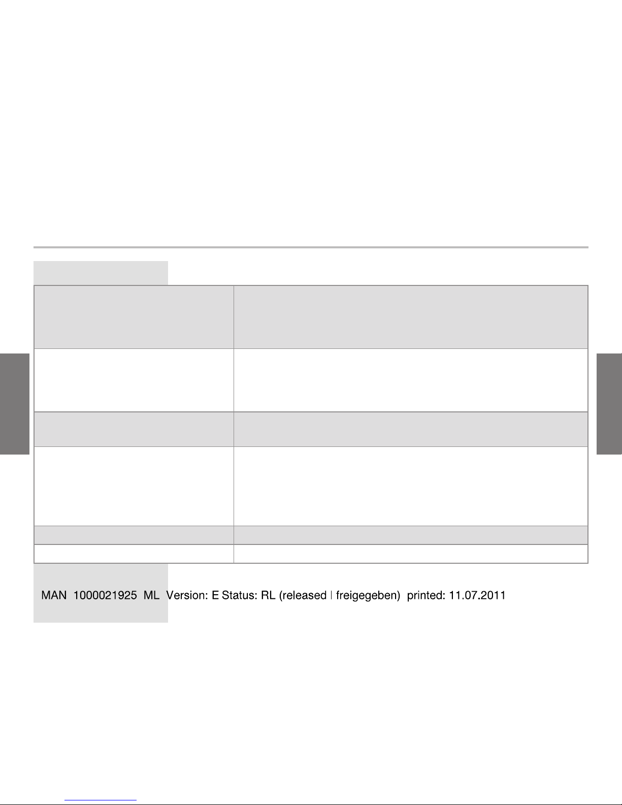
Type Electrical connection Order code
Namur II 1 G/D EN 175301-803 male fixed
connector
552901
Namur I M1 553455
3.3. Ordering table for spare parts and
accessories
Spare part or accessory Order code
EN 175301-803 female connector (type 2508) with
blue cable gland and silicone seal
167526
Mechanical protection for SE30 Ex "Namur I M1" 553519
Page 14
ENGLISH
ENGLISH
Flow sensor SE30 Ex
3.4. Ordering table for intrinsic safety barriers
Supply
voltage
Output Number of channels Order code
24 VDC open collector,
15 V, 60 mA
2, with on/off or Namur
contact inputs
553456
4, with on/off or Namur
contact inputs
553457
230 VAC open collector,
15 V, 60 mA
2, with on/off or Namur
contact inputs
553458
4, with on/off or Namur
contact inputs
553459
Page 15
15
ENGLISH
ENGLISH
SE30 Ex
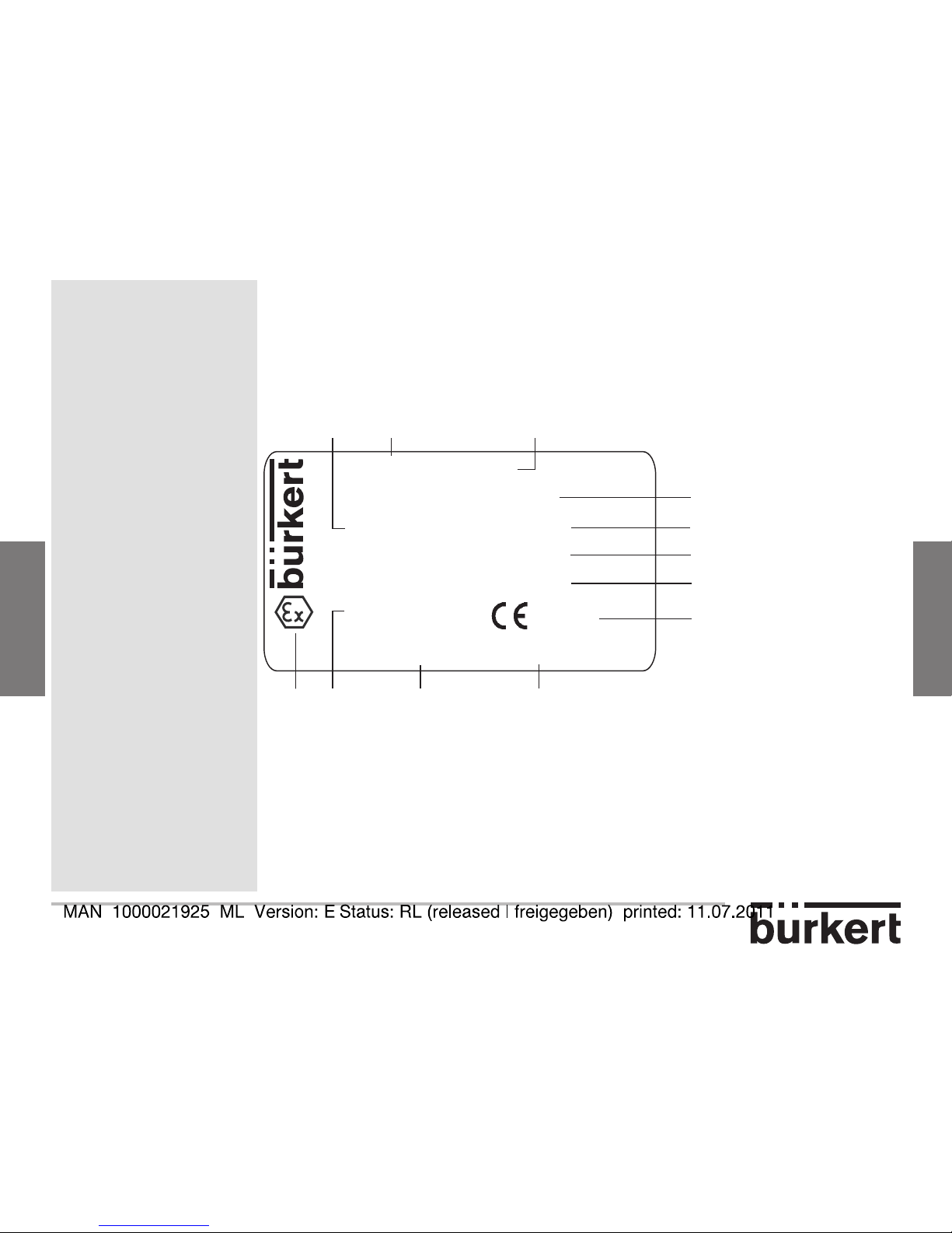
3.5. Description of the nameplate SE30 Ex
SE30EX-NAMUR
II 1 G/D Ex ia IIC T6
Ex iaD 20 IP6X T80°C
Tamb : 0°C - +60°C
LCIE 04 ATEX 6070 X
S/N:1000
00552901 W46LN
F-67220 TRIEMBACH
1 3
5
7
11
9
6
10
4
12
0102
2
8
1. Protection rating
2. Type of sensor
3. Type of supply/output
4. ATEX classification
5. Maximum surface temperature
Page 16
ENGLISH
ENGLISH
Flow sensor SE30 Ex
6. Ambient operating temperature
7. Certification body and ATEX number
8. CE logo and code of notified body that inspected the site
9. Construction code and manufacturing year code
10. Order code
11. Serial number
12. Ex Logo
Page 17

17
ENGLISH
ENGLISH
SE30 Ex
Page 18
ENGLISH
ENGLISH
Flow sensor SE30 Ex
4. technical data
4.1. General data
Pipe diameter
• with fitting S030
• with fitting S070
• DN6 to DN65
• DN6 to DN50
Fluid temperature
• with fitting S030
• with fitting S070
• -15 to +80 °C
• max. +80 °C
Velocity measuring range with a
fitting S030
0,3 m/s to 10 m/s
Velocity measuring range with a
fitting S070
• viscosity > 5cps
• viscosity < 5 cps
• 1 to 1200 l/min
• 3 to 616 l/min
Linearity ±0.5 % of the full scale
1)
Repeatability 0.4% of the measured value
Page 19
19
ENGLISH
ENGLISH
SE30 Ex
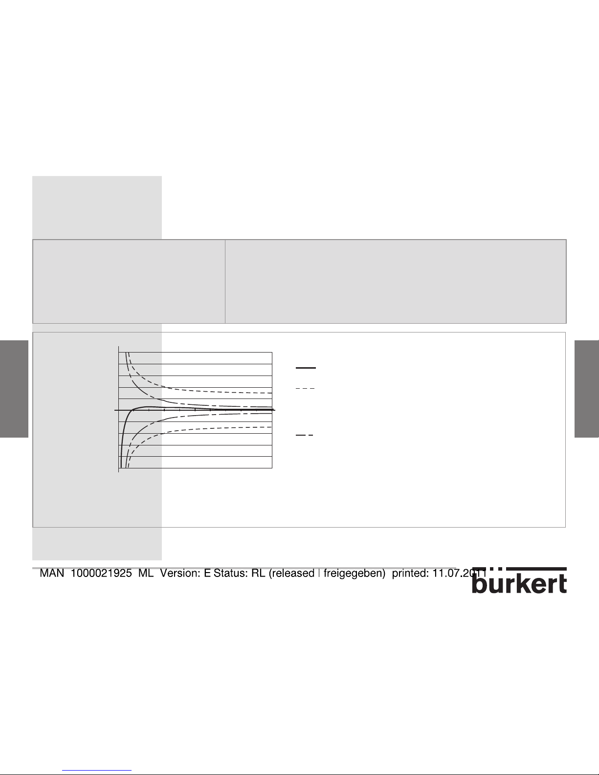
Accuracy (see Fig. 1) • ±0,5 % of the full scale 1), with calibration on site (e.g.,
using Teach-in feature of a transmitter 8025, remote
version)
• ± (0,5 % of the full scale
1)
+ 2,5 % of the measured
value), with standard K factor
Measuring error - % of
the measure
1
9
23
4567810
2
4
6
8
10
-2
-4
-6
-8
-10
Max. error [%]
Fluid velocity [m/s]
Typical Bürkert curve
with standard K factor (without calibration on site) (=
0.5% of the full scale + 2.5% of the measured value)
with calibration on site (= 0.5% of the full scale)
These values have been determined in the following reference conditions: medium = water, water and
ambient temperatures = 20 °C, min. straight upstream and downstream distances respected, appropriate
pipe dimensions
Fig. 1: Measurement accuracy, with (using Teach-in of a 8025 transmitter for instance) and
without calibration on site
Page 20
ENGLISH
ENGLISH
Flow sensor SE30 Ex
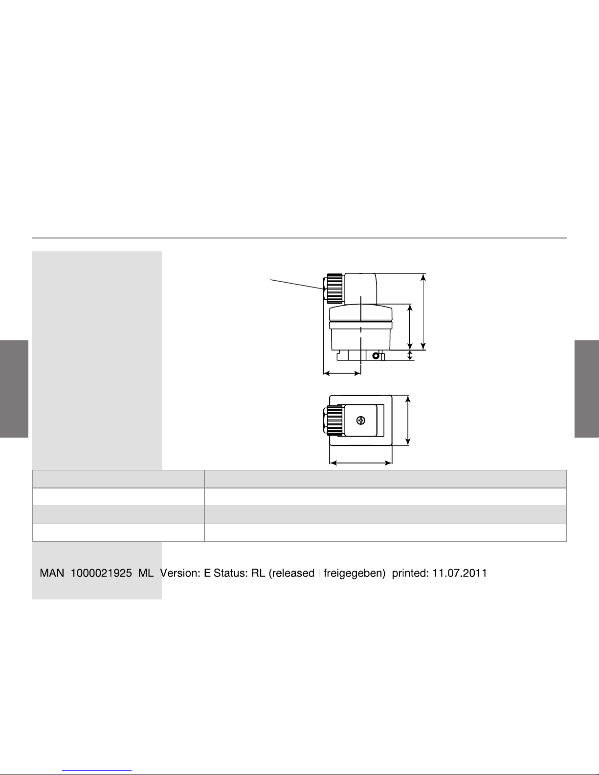
4.2. Dimensions (mm) and materials
32
40
66
44
54
9
Female connector
type 2508
EN 175301-803 connector PA, with silicone seal
Housing PPS, glass fiber reinforced
Housing of fitting S030
1)
brass, stainless steel or PVDF
Housing of fitting S070
1)
aluminium or stainless steel
1)
See chapter «safety instructions - notice of ATEX instructions» to select the appropriate fitting
Page 21
21
ENGLISH
ENGLISH
SE30 Ex
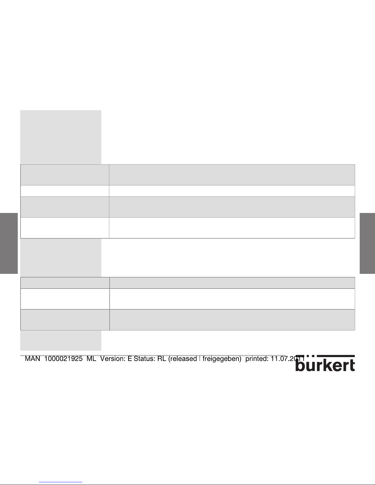
4.3. Electrical data
Power supply
2)
Marking I M1 and II 1 G/D: supplied by the intrinsic safety barrier with
NAMUR input (DIN 60947-5-6)
Current consumption max. 7 mA
Protection against
polarity reversal
yes
Output signal 0.5 or 2.5 mA, through both supply wires, current modulation
according to NAMUR standard
2)
See chapter «safety instructions - notice of ATEX instructions» to select the appropriate power supply depending on the use site.
4.4. Electrical connections
Female connector EN 175301-803 (type 2508, supplied)
Type of cable
recommended
shielded, cross section between 0.5 and 1.5 mm2, line impedance
< 50 W
Cable length max. 50 m, shielded (up to 500 m depending on line impedance and
power consumption)
Page 22
ENGLISH
ENGLISH
Flow sensor SE30 Ex
4.5. Environment
Ambient temperature 0 to +60° C
Relative humidity < 80%, non condensated
Protection rating of the
housing
IP 67 acc. to EN60529, connector plugged-in and cable gland
tightened
Page 23
23
ENGLISH
ENGLISH
SE30 Ex
Page 24
ENGLISH
ENGLISH
Flow sensor SE30 Ex
5.1. General recommendations
Systematically verify the chemical compatibility of the equipment of which
the sensor is composed and the products likely to come into contact with
it.
Your Bürkert supplier will be happy to assist you with any additional
information.
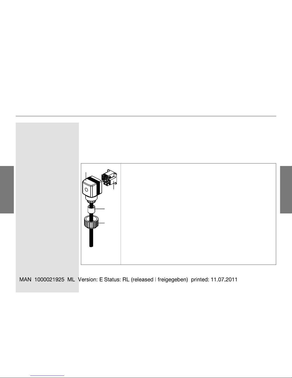
5.2. Assembling and mounting on the pipe
The SE30 Ex electronic module is connected to an S030 or S070 fitting
(DN6 to DN50) that allows it to be installed on a pipe.
Use only fittings with brass, stainless steel, aluminium or PVDF
housings. Any other fittings are prohibited in explosive areas.
In firedamp mines use only fittings with brass or stainless steel
housings and for an S030 fitting with a PVDF paddle-wheel.
Comply with the «Safety instructions and ATEX instruction notice»
for the type of fluid connection that can be used depending on the
place of installation in potentially explosive atmospheres.
→ During mounting, follow the instructions given with the fitting.
5. Installation and wiring
Page 25

25
ENGLISH
ENGLISH
SE30 Ex
Fig. 2: Assembling the SE30 Ex and a fitting S030
Page 26
ENGLISH
ENGLISH
Flow sensor SE30 Ex
5.3. Electrical connection
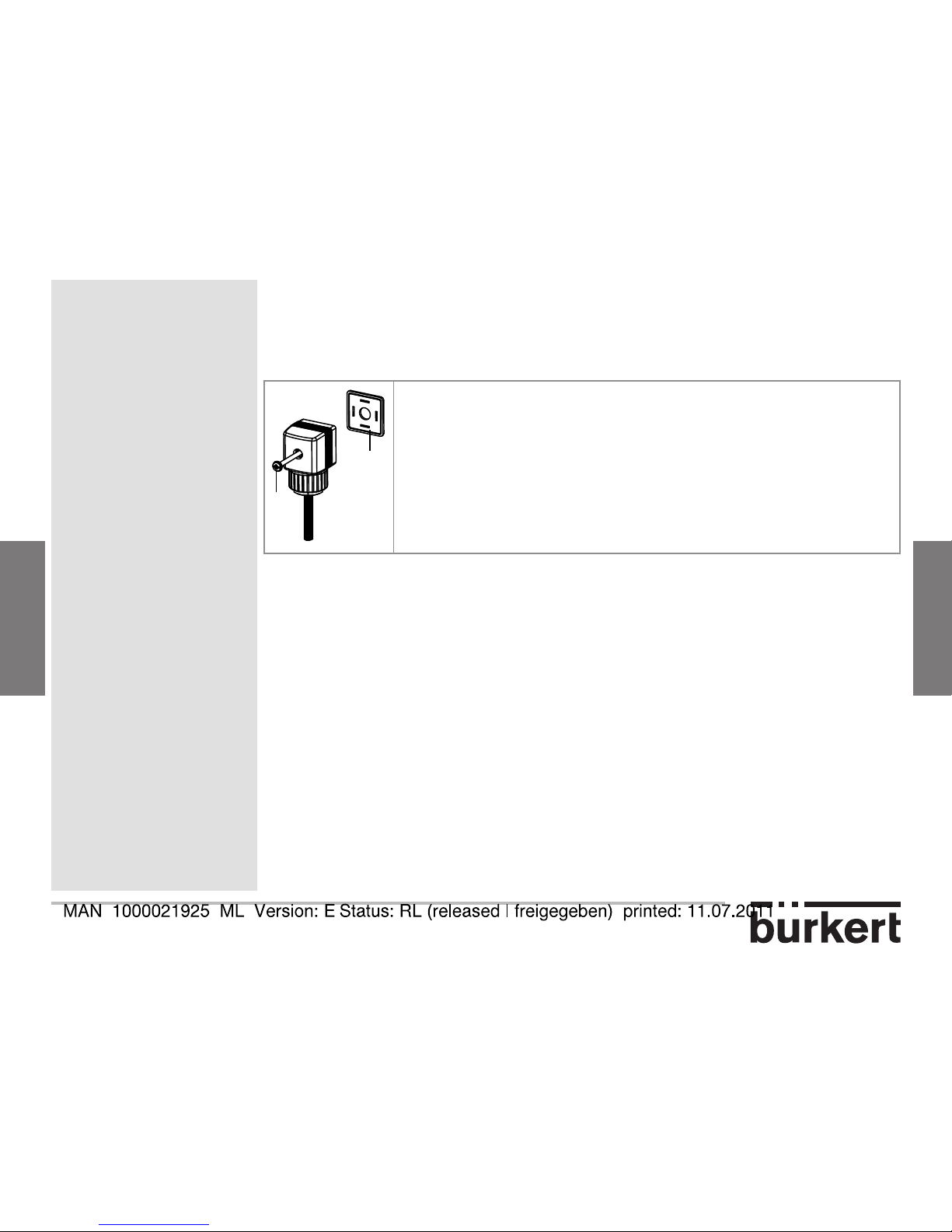
5.3.1. Assembling the female connector type
2508
1
2
3
4
→ Unscrew the nut [1] on the cable gland.
→ Remove the screw terminal block [3] from the
housing [2].
→ Insert the cable into the nut [1] and then the seal [4],
into the cable gland and finally through the housing
[2].
→ Make the connections to the screw terminal block [3]
(see chap. 5.3.2).
→ Position the terminal block [3] in steps of 90° and
then put it back into the housing [2], pulling gently on
the cable so that the wires do not clutter the housing.
→ Tighten the nut [1] on the cable gland.
Page 27
27
ENGLISH
ENGLISH
SE30 Ex
6
5
→ Place the seal [5] between the connector and the
EN175301-803 fixed connector on the device
and then insert the 2508 connector into the fixed
connector.
→ Insert and then tighten the screw [6] to ensure
correct tightness and electrical contact.
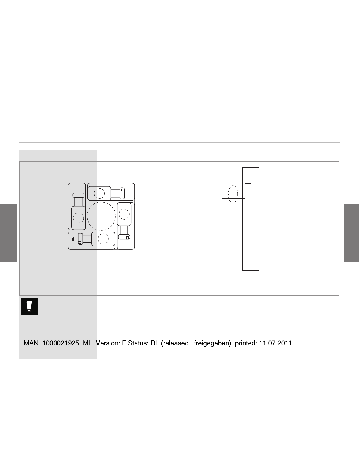
5.3.2. Wiring of the SE30 Ex, marking II 1 G/D
or 1 M1 (with NAMUR intrinsic safety
barrier)
Always ensure the power supply is switched off before working on the
device. The connector must be plugged out.
Use:
• a shielded cable with an operating temperature suited to the process
conditions
• an intrinsic safety barrier with NAMUR input and complying with the
Safety instructions - notice of ATEX instructions.
Page 28
ENGLISH
ENGLISH
Flow sensor SE30 Ex
EN 175301-803 connector
Intrinsic safety barrier
1)
1
3
2
+
-
L+
L-
SE30 Ex
Earth the shielding of the cable on side of the measuring
exploitation.
1)
Use an appropriate power supply which complies with the safety instruction - notice of ATEX instructions.
Page 29

29
ENGLISH
ENGLISH
SE30 Ex
Page 30

ENGLISH
ENGLISH
Flow sensor SE30 Ex
6.1. Possible connections with the SE30 Ex flow sensor
Type 8032
Wall-mounted
Type 8025 Universal
Wall- or panel-mounted
Type 8025 Batch
Wall- or panel-mounted
SE30 Ex + S030
PLC
PLC
Potentially
explosive
area
Intrinsic saftey
barrier
6. Annex
Page 31

31
ENGLISH
ENGLISH
SE30 Ex
6.2. Connection example with the SE30 Ex and the externally
powered intrinsic safety barrier
Refer to the instruction manual of transmitter 8025 Universal for any other wiring
instruction.
SE30 Ex
8025 Universal
+
-
L+
L -
+
-
NPN/PNP
SUPP L Y
COIL
1
2
3
4
PE
NC
3A/230 V A C
REL1
REL2
SENSOR SUPP L Y
FLOW SENSOR
SOURCE SINK
CURRENT
Iout L+ L -
Supply
13..30Vdc
PE
PE PE
NC
NC
+
-
PULSE INPUT
1
2
3
L+
+12V
+5V
P- P+
PULSE
OUTPUT
1 2 3
COIL
NPN
PNP
NPN
470
2.2K
FLOW SENSOR
SENSOR
INPU T LOA D
39K
COIL
PNP
24 VDC ± 10%
/ 230 VAC
B A
ON
1 2
1
2
3
Potentially explosive
area
Safe area
Intrinsic safety barrier
(remove blue mask on front
to access the switches)
Position of these switches is
indifferent
Set both
switches to ON
Position of 8025 Universal switches:
- «SENSOR INPUT LOAD» = «1»
(2.2 kW)
- «FLOW SENSOR» = «NPN/PNP»
- «SENSOR SUPPLY» = indifferent
Power supply
Fig. 3: Connection between an SE30 Ex and a panel version of the transmitter 8025 Universal.
Page 32

ENGLISH
ENGLISH
Flow sensor SE30 Ex
6.3. Connection example with the SE30 Ex and the intrinsic
safety barrier, 24 VDC, powered through the transmitter
Refer to the instruction manual of transmitter 8025 Universal for any other wiring
instruction.
SE30 Ex
8025 Universal
+
-
L+
L-
+
-
NPN/PNP
SUPPLY
COIL
1
2
3
4
PE
NC
3A/230VAC
REL1
REL2
SENSOR SUPPLY
FLOW SENSOR
SOURCE SINK
CURRENT
Iout L+ L-
Supply
13..30Vdc
PE
PE PE
NC
NC
+
-
PULSE INPUT
1
2
3
L+
+12V
+5V
P- P+
PULSE
OUTPUT
123
COIL
NPN
PNP
NPN
470
2.2K
FLOW SENSOR
SENSOR
INPUT LOAD
39K
COIL
PNP
24 VDC ± 10%
BA
ON
12
1
2
3
+-
+
-
Potentially explosive area Safe area
Intrinsic safety barrier
(remove blue mask on front
to access the switches)
Position of these switches is indifferent
Set both switches to ON
Position of 8025 Universal switches:
- «SENSOR INPUT LOAD» = «1»
(2.2 kW)
- «FLOW SENSOR» = «NPN/PNP»
- «SENSOR SUPPLY» = «3» (L+)
Power supply
Fig. 4: Connection between an SE30 Ex and a panel version of the transmitter 8025 Universal.
Page 33

Manuel utilisateur
00553593 - 1107/0_Original_FR
CAPTEUR DE DEBIT POUR ATMOSPHERES EXPLOSIBLES
II 1 G/D
I M 1
© Bürkert 2004-2011 Sous réserve de modifications techniques
Page 34

FRANCAIS
FRANCAIS
Capteur de débit SE30 Ex
1. DÉCLARATION DE CONFORMITÉ ...................................................................................................................4
2. CONSIGNES DE SÉCURITÉ - NOTICE D’INSTRUCTIONS ATEX ...................................................6
2.1. Utilisation .........................................................................................................................................................6
2.2. Garantie légale et responsabilité ........................................................................................................9
2.3. Précautions lors de l‘installation et la mise en service ........................................................10
2.4. Traçabilité ......................................................................................................................................................11
3. DESCRIPTION .........................................................................................................................................................12
3.1. Construction et principe de mesure ............................................................................................... 12
3.2. Références de commande des capteurs de débit SE30 Ex ..............................................13
3.3. Références de commande des pièces détachées et accessoires ................................13
3.4. Références de commande des barrières de sécurité intrinsèque .................................14
3.5. Description de l’étiquette du capteur SE30 Ex .........................................................................15
4. CARACTÉRISTIQUES TECHNIQUES ......................................................................................................... 18
4.1. Caractéristiques générales ..................................................................................................................18
4.2. Dimensions (mm) et matériaux .........................................................................................................20
4.3. Caractéristiques électriques ...............................................................................................................21
Page 35

3
FRANCAIS
FRANCAIS
SE30 Ex
4.4. Raccordement électrique ..................................................................................................................... 21
4.5. Environnement ...........................................................................................................................................22
5. INSTALLATION ET CÂBLAGE..........................................................................................................................24
5.1. Recommandations générales ............................................................................................................24
5.2. Assemblage et installation sur la conduite.................................................................................24
5.3. Raccordement électrique ..................................................................................................................... 26
5.3.1. Assemblage du connecteur femelle type 2508 .............................................................. 26
5.3.2. Câblage du SE30 Ex, version II 1 G/D ou I M1 (avec barrière de sécurité NAMUR) 27
6. ANNEXE ..................................................................................................................................................................... 30
6.1. Raccordements possibles avec le capteur SE30 Ex .............................................................30
6.2. Exemple de raccordement avec le SE30 Ex et la barrière SI alimentée en
externe ............................................................................................................................................................32
6.3. Exemple de raccordement avec le SE30 Ex et la barrière SI, 24 VDC,
alimentée par le transmetteur............................................................................................................33
Page 36

FRANCAIS
FRANCAIS
Capteur de débit SE30 Ex
1. Déclaration de conformité
Nous, Bürkert, déclarons en tant que fabricant que le produit suivant :
DEBITMETRE ELECTRONIQUE
Type SE30 Ex NAMUR
ayant le marquage II 1 G/D ou I M1, satisfait aux exigences :
• de la directive 94/9/CE portant sur les appareils destinés à être utilisés
en atmosphères explosives. Pour l’évaluation, les normes suivantes ont
été prises en compte :
- EN 60079-0 (2006)
- EN 60079-11 (2007)
- EN 61241-0 (2004)
- EN 61241-11 (2007)
• de la directive 2004/108/CEE portant sur la compatibilité électromagnétique. Pour l’évaluation, les normes suivantes ont été prises en
compte :
- Emission selon EN 61000-6-3 (2007)
- Immunité selon EN 61000-6-2 (2005)
Page 37

5
FRANCAIS
FRANCAIS
SE30 Ex
L’attestation d’examen CE de type LCIE 04 ATEX 6070 X a été établie
par le LCIE (Laboratoire Central des Industries Electriques, 33 avenue du
Gal Leclerc, BP 8, F-92266 Fontenay-aux-Roses).
Sous réserve d’une utilisation conforme à leur destination et/ou d’une
installation conforme aux normes en vigueur et/ou aux recommandations
du constructeur et des conditions spéciales pour une utilisation sûre
précisées dans l’attestation d’examen CE de type. Voir le chapitre 2 de
ce manuel.
L’évaluation du système qualité N° PTB 98 ATEX Q008-2 a été établie
par le PTB (Physikalisch-Technische Bundesanstalt, Bundesallee 100,
D-38116 BRAUNSCHWEIG).
Triembach-au-Val, le 18/02/2010 Assurance Qualité
Bürkert S.A.S Bruno Thouvenin
Rue du Giessen
F-67220 Triembach-au-Val
Page 38

FRANCAIS
FRANCAIS
2. Consignes de sécurité - Notice d’instructions ATEX
Respecter les consignes de sécurité, repérées par le symbole cicontre, ainsi que toutes les instructions contenues dans ce manuel.
Respecter les recommandations spécifiques ATEX repérées par le
symbole ci-contre.
2.1. Utilisation
Le capteur SE30 Ex est destiné à la mesure du débit dans des liquides
neutres ou légèrement agressifs et exempts de particules solides, dans
les zones explosives suivantes :
• zones 0, 1 ou 2 et zones 20, 21, 22 matériel de catégorie II 1 G/D
• mines grisouteuses matériel de catégorie I M1
Modèle SE30 Ex NAMUR identifiant 552901 pour zones explosibles
gaz (0, 1 et 2) et/ou poussières (20, 21 et 22)
• Aide à la compréhension du marquage et à l’installation :
CE 0102
II 1 GD
Ex ia IIC T6
Ex iaD 20 IP6X T80°C
T ambiante : 0°C ≤ Ta ≤ 60°C
LCIE 04 ATEX 6070 X
Page 39

7
FRANCAIS
FRANCAIS
SE30 Ex
• Conditions spéciales pour une utilisation sûre :
- L’appareil est un matériel à sécurité intrinsèque.
- Il peut être installé en atmosphères explosibles : zones 0, 1 ou 2 et/ou
zones 20, 21 ou 22.
- Le connecteur ne doit être raccordé qu’à un matériel certifié de
sécurité intrinsèque. Ces associations doivent être compatibles vis
à vis de la sécurité intrinsèque en respectant les paramètres ci-dessous.
- Température ambiante d’utilisation : de 0 °C à +60 °C
• Paramètres spécifiques du ou des modes de protection concernés :
Ui ≤ 15V, Ii ≤ 50 mA, Pi ≤ 188 mW, Ci ≤ 1,2 nF, Li ≅ 0
• Montage mécanique et raccords fluidiques compatibles avec ce marquage et cette utilisation :
Utiliser uniquement des raccords en laiton, acier inoxydable, aluminium
ou PVDF.
Si le raccord comporte une ailette en PP, s’assurer qu’à l’intérieur de
la canalisation, il n’y a aucun risque d’explosion : la partie fluidique
doit être hors zone ATEX.
• Les autres raccords sont interdits en zone explosible.
Page 40

FRANCAIS
FRANCAIS
Capteur de débit SE30 Ex
Modèle SE30 Ex NAMUR identifiant 553455 pour mines
grisouteuses
• Aide à la compréhension du marquage et à l’installation
CE 0102
I M1
Ex ia I T80°C
T ambiante : 0°C ≤ Ta ≤ 60°C
LCIE 04 ATEX 6070 X
• Conditions spéciales pour une utilisation sûre :
- L’appareil est un matériel à sécurité intrinsèque pour mines grisouteuses.
- Il peut être installé en atmosphères explosibles : mine.
- Le connecteur ne doit être raccordé qu’à un matériel certifié de
sécurité intrinsèque. Ces associations doivent être compatibles vis
à vis de la sécurité intrinsèque en respectant les paramètres ci-dessous.
- Température ambiante d’utilisation : de 0 °C à +60 °C
• Paramètres spécifiques du ou des modes de protection concernés :
Ui ≤ 15V, Ii ≤ 50 mA, Pi ≤ 188 mW, Ci ≤ 1,2 nF, Li ≅ 0
Page 41

9
FRANCAIS
FRANCAIS
SE30 Ex
• Montage mécanique et raccords fluidiques compatibles avec ce marquage et cette utilisation :
- Utiliser uniquement des raccords en laiton ou acier inoxydable et,
pour un raccord S030, une ailette en PVDF.
- Tout autre raccord est interdit.
- Le matériel doit être protégé contre les dommages mécaniques. Il
conviendra d’utiliser la protection mécanique référence 553519.
2.2. Garantie légale et responsabilité
Pendant et hors période de garantie, seule la société Bürkert est autorisée à effectuer les réparations ou modifications d’un de ses produits
ayant fait l’objet de l’établissement d’une attestation d’examen CE de
type. Bürkert dégage sa responsabilité, dans le cas du non-respect de
cette clause.
Les travaux de montage doivent être réalisés par un personnel
qualifié. En cas de difficultés lors de l‘installation ou de la mise en
service, veuillez contacter votre fournisseur Bürkert dans les plus
brefs délais.
Page 42

FRANCAIS
FRANCAIS
Capteur de débit SE30 Ex
2.3. Précautions lors de l‘installation et la
mise en service
• Veillez toujours à la compatibilité chimique des matériaux en contact
avec le fluide à mesurer.
• De même, lors du nettoyage de l‘appareil, veillez à utiliser des produits
chimiquement compatibles avec les matériaux de l‘appareil.
• Protéger l’appareil contre les perturbations électromagnétiques, les
rayons ultraviolets et, lorsqu'il est installé à l'extérieur, des effets des
conditions climatiques.
Ce matériel doit être installé conformément aux dispositions de la
norme EN 60079-14 : Matériel électrique pour atmosphères explosives gazeuses.
Partie 14 : installations électriques dans les emplacements dangereux (autres que les mines).
Lors du démontage du capteur de la conduite, prenez toutes les
précautions liées au procédé.
Page 43

11
FRANCAIS
FRANCAIS
SE30 Ex
2.4. Traçabilité
Les produits SE30 Ex sont identifiés par un numéro de série individuel
qui permet la traçabilité. Ce numéro (5 chiffres), associé à l’année, est
inscrit sur l’étiquette d’identification portant la référence complète de
l’appareil.
Ce produit est un matériel pour atmosphères explosibles. A ce titre, et
en respect de la directive ATEX 94/9/CE, des dispositions doivent être
prises pour assurer la traçabilité ascendante et descendante. Notre
système qualité notifié ATEX assure cette traçabilité jusqu’au premier
point de livraison.
Sauf dispositions écrites contractuelles contraires, toute personne
assurant une relivraison de ce matériel s’engage à mettre en place un
système permettant une éventuelle procédure de rappel de matériel non
conforme.
Page 44

FRANCAIS
FRANCAIS
Capteur de débit SE30 Ex
3. Description
3.1. Construction et principe de mesure
Le capteur de débit SE30 Ex est un module électronique qui doit être
associé à un élément de mesure, un raccord S030 (en laiton, acier inoxydable ou PVDF) ou S070.
En fonction de son lieu d’utilisation, le capteur SE30 Ex doit être
raccordé selon les éléments donnés dans les consignes de sécurité
- notices d’instructions ATEX
Le capteur détecte la rotation de l’ailette et module le courant de la ligne
d’alimentation suivant la norme Namur (0,5 mA ou 2,5 mA). La fréquence
f de modulation est proportionnelle au débit Q, selon la formule f = K.Q.
f = fréquence en Hz
K = facteur K spécifique à chaque raccord, en impulsion/l
Q = débit en l/s
Afin d’exploiter ce signal, connecter une barrière de sécurité intrinsèque
de type Namur au SE30 Ex. Elle détecte la modulation et la convertit en
fréquence sur sa sortie collecteur ouvert.
Le raccordement électrique s‘effectue via un connecteur EN 175301-803
(type 2508).
Page 45

13
FRANCAIS
FRANCAIS
SE30 Ex
3.2. Références de commande des capteurs
de débit SE30 Ex
Toutes les versions du capteur de débit SE30 Ex :
• sont alimentées par une barrière à sécurité intrinsèque,
• présentent une sortie Namur.
Type Raccordement électrique Référence de
commande
Namur II 1 G/D Embase mâle EN 175301-803 552901
Namur I M1 553455
3.3. Références de commande des pièces
détachées et accessoires
Pièce détachée ou accessoire Référence de
commande
Connecteur femelle type 2508 (selon EN 175301-
803), avec presse-étoupe bleu et joint en silicone
167526
Page 46

FRANCAIS
FRANCAIS
Capteur de débit SE30 Ex
Pièce détachée ou accessoire Référence de
commande
Protection mécanique pour version SE30 Ex "Namur
I M1"
553519
3.4. Références de commande des barrières
de sécurité intrinsèque
Tension Sortie Nombre de voies Référence de
commande
24 VDC Collecteur ouvert,
15 V, 60 mA
2, avec entrées contact
sec ou Namur
553456
4, avec entrées contact
sec ou Namur
553457
230 VAC Collecteur ouvert,
15 V, 60 mA
2, avec entrées contact
sec ou Namur
553458
4, avec entrées contact
sec ou Namur
553459
Page 47

15
FRANCAIS
FRANCAIS
SE30 Ex
3.5. Description de l’étiquette d'identification
du capteur SE30 Ex
SE30EX-NAMUR
II 1 G/D Ex ia IIC T6
Ex iaD 20 IP6X T80°C
Tamb : 0°C - +60°C
LCIE 04 ATEX 6070 X
S/N:1000
00552901 W46LN
F-67220 TRIEMBACH
1 3
5
7
11
9
6
10
4
12
0102
2
8
1. Indice de protection
2. Type de capteur
3. Type d’alimentation/de sortie
4. Classification ATEX
Page 48

FRANCAIS
FRANCAIS
Capteur de débit SE30 Ex
5. Température maximale de surface
6. Température ambiante de fonctionnement
7. Organisme certificateur et numéro ATEX
8. Logo CE et code de l’organisme notifié ayant audité le site
9. Code de fabrication et code année
10. Référence de commande
11. Numéro de série
12. Logo Ex
Page 49

17
FRANCAIS
FRANCAIS
SE30 Ex
Page 50

FRANCAIS
FRANCAIS
Capteur de débit SE30 Ex
4. Caractéristiques techniques
4.1. Caractéristiques générales
Diamètre des conduites
• avec raccord S030
• avec raccord S070
• DN6 à DN65
• DN6 à DN50
Température du fluide
• avec raccord S030
• avec raccord S070
• -15 à +80 °C
• max. +80 °C
Plage de mesure de vitesse avec
raccord S030
0,3 m/s à 10 m/s
Plage de mesure de vitesse avec
raccord S070
• viscosité > 5cps
• viscosité < 5 cps
• 1 à 1200 l/min
• 3 à 616 l/min
Linéarité ±0.5 % de la Pleine Echelle
1)
Répétabilité 0.4% de la Valeur Mesurée
Page 51

19
FRANCAIS
FRANCAIS
SE30 Ex
Précision (voir Fig. 1) • ±0,5 % de la Pleine Echelle 1), avec calibration sur site
(par exemple en utilisant la fonction Teach-in d’un transmetteur 8025 en version déportée)
• ± (0,5 % de la Pleine Echelle
1)
+ 2,5 % de la Valeur
Mesurée), avec facteur K du raccord
Erreur de mesure -
% de la mesure
1
9
23
4567810
2
4
6
8
10
-2
-4
-6
-8
-10
Erreur max. [%]
Vitesse du fluide [m/s]
Courbe typique Bürkert
avec facteur K du raccord utilisé (sans calibrage sur
site) (= 0.5% Pleine Echelle + 2.5% Valeur mesurée)
avec calibrage sur site (= 0.5% Pleine Echelle)
Ces valeurs ont été déterminées dans les conditions de référence suivantes : fluide = eau, températures du
fluide et ambiante = 20 °C, distances amont et aval respectées, dimensions des conduites adaptées.
Fig. 1 : Précision de la mesure avec (fonction Teach-in d’un transmetteur 8025 par exemple) et
sans calibration sur site
Page 52

FRANCAIS
FRANCAIS
Capteur de débit SE30 Ex
4.2. Dimensions (mm) et matériaux
32
40
66
44
54
9
Connecteur femelle
2508
Connecteur EN 175301-803 PA, avec joint en silicone
Boîtier PPS renforcé en fibres de verre
Corps du raccord S030
1)
laiton, acier inoxydable ou PVDF
Corps du raccord S070
1)
aluminium ou acier inoxydable
1)
Se reporter à la rubrique «Consignes de sécurité - Notice d’instructions ATEX» pour choisir un raccord
adapté
Page 53

21
FRANCAIS
FRANCAIS
SE30 Ex
4.3. Caractéristiques électriques
Alimentation
2)
Version I M1 ou II 1 G/D : fournie par la barrière de sécurité intrin-
sèque à entrée NAMUR (DIN 60947-5-6)
Consommation max. 7 mA
Protection contre
l‘inversion de polarité
oui
Signal de sortie 0,5 ou 2,5 mA, par les 2 fils de l’alimentation, modulation du courant
suivant la norme NAMUR
2)
Se reporter à la rubrique «Consignes de sécurité - Notice d’instructions ATEX» pour choisir l’alimentation adaptée en fonction du lieu
d’utilisation
4.4. Raccordement électrique
Connecteur femelle EN 175301-803 (type 2508, fourni)
Type de câble
recommandé
blindé, section comprise entre 0,5 et 1,5 mm
2
, impédance de ligne
< 50 W
Longueur de câble max. 50 m, blindé (jusqu’à 500 m en fonction de l’impédance de ligne
et la consommation)
Page 54

FRANCAIS
FRANCAIS
Capteur de débit SE30 Ex
4.5. Environnement
Température ambiante 0 à +60° C
Humidité relative < 80%, non condensée
Classe de protection
du boîtier
IP 67 selon EN60529, avec connecteur enfiché et presse-étoupe serré
Page 55

23
FRANCAIS
FRANCAIS
SE30 Ex
Page 56

FRANCAIS
FRANCAIS
Capteur de débit SE30 Ex
5.1. Recommandations générales
Vérifier systématiquement la compatibilité chimique des matériaux composants le capteur et les produits susceptibles d’entrer en contact avec
celui-ci.
Votre fournisseur Bürkert reste à votre entière disposition pour tous renseignements complémentaires.
5.2. Assemblage et installation sur la conduite
Le module électronique SE30 Ex est associé à un raccord S030 ou
S070 (DN6 à DN50) qui permet son installation sur une conduite.
Utiliser uniquement des raccords avec corps en laiton, acier inoxydable, aluminium ou PVDF. Les autres raccords sont interdits en
zone explosible.
Dans les mines grisouteuses, utiliser uniquement des raccords avec
corps en acier inoxydable ou laiton et, pour le raccord S030, une
ailette en PVDF.
Respecter les «Consignes de sécurité et Notice d’instructions ATEX»
pour le type de raccord fluidique utilisable en fonction du lieu d’ins-
5. Installation et câblage
Page 57

25
FRANCAIS
FRANCAIS
SE30 Ex
tallation en atmosphères explosibles.
→ Lors de l’installation, respecter les consignes livrées avec le raccord.
Fig. 2 : Montage du SE30 Ex sur un raccord S030
Page 58

FRANCAIS
FRANCAIS
Capteur de débit SE30 Ex
5.3. Raccordement électrique
5.3.1. Assemblage du connecteur femelle
type 2508
1
2
3
4
→ Dévisser l'écrou [1] du presse-étoupe.
→ Extraire le bornier à vis [3] du boîtier [2].
→ Insérer le câble dans l'écrou [1] puis dans le joint
[4], dans le presse-étoupe et pour finir, à travers le
boîtier [2].
→ Effectuer les connexions sur le bornier à vis [3] (voir
chap. 5.3.2).
→ Orienter le bornier [3] par pas de 90° puis le replacer
dans le boîtier [2] en tirant légèrement sur le câble
pour que les fils n'encombrent pas le boîtier.
→ Serrer l'écrou [1] du presse-étoupe.
Page 59

27
FRANCAIS
FRANCAIS
SE30 Ex
6
5
→ Placer le joint [5] entre le connecteur et l'embase
EN175301-803 de l'appareil puis insérer le connecteur 2508 sur l'embase.
→ Insérer puis serrer la vis [6] pour assurer l’étanchéité
et un contact électrique correct.
5.3.2. Câblage du SE30 Ex, version II 1 G/D ou
I M1 (avec barrière de sécurité NAMUR)
Assurez-vous toujours que l‘appareil est hors tension avant d‘effectuer toute
intervention. Le connecteur doit être débranché.
Utiliser :
• un câble blindé avec une température limite de service adaptée au
process.
• une barrière de sécurité intrinsèque de type NAMUR, et conforme aux
consignes de sécurité et à la notice d’instructions ATEX
Page 60

FRANCAIS
FRANCAIS
Capteur de débit SE30 Ex
Embase mâle EN 175301-803
du SE30 Ex
Barrière de sécurité intrinsèque
1)
1
3
2
+
-
L+
L-
SE30 Ex
Raccorder le blindage à la terre du côté exploitation de la mesure.
1)
Utiliser une alimentation adaptée et conforme aux consignes de sécurité et à la notice d’instructions ATEX.
Page 61

29
FRANCAIS
FRANCAIS
SE30 Ex
Page 62

FRANCAIS
FRANCAIS
Capteur de débit SE30 Ex
6.1. Raccordements possibles avec le capteur SE30 Ex
Type 8032
Mural
Type 8025 Universal
Mural ou encastrable
Type 8025 Batch
Mural ou encastrable
SE30 Ex + S030
Automate
PLC
Zone
explosible
Barrière SI
6. Annexe
Page 63

31
FRANCAIS
FRANCAIS
SE30 Ex
6.2. Exemple de raccordement avec le SE30 Ex et la barrière
SI alimentée en externe
Se référer au manuel utilisateur du transmetteur 8025 Universal pour les autres
connexions du 8025.
SE30 Ex
8025 Universal
+
-
L+
L -
+
-
NPN/PNP
SUPP L Y
COIL
1
2
3
4
PE
NC
3A/230 V A C
REL1
REL2
SENSOR SUPP L Y
FLOW SENSOR
SOURCE SINK
CURRENT
Iout L+ L -
Supply
13..30Vdc
PE
PE PE
NC
NC
+
-
PULSE INPUT
1
2
3
L+
+12V
+5V
P- P+
PULSE
OUTPUT
1 2 3
COIL
NPN
PNP
NPN
470
2.2K
FLOW SENSOR
SENSOR
INPU T LOA D
39K
COIL
PNP
24 VDC ± 10%
/ 230 VAC
B A
ON
1 2
1
2
3
Zone explosible Hors zone explosible
Barrière de sécurité intrinsèque (retirer le cache
bleu de la face avant pour
accéder aux interrupteurs).
La position de ces interrupteurs est
indifférente.
Mettre les 2
interrupteurs sur
ON.
Position des interrupteurs du 8025
Universal :
- «SENSOR INPUT LOAD» = «1»
(2.2 kW)
- «FLOW SENSOR» = «NPN/PNP»
- «SENSOR SUPPLY» = indifférente
Alimentation
Fig. 3 : Raccordement du SE30 Ex à un transmetteur 8025 Universal en version encastrable.
Page 64

FRANCAIS
FRANCAIS
Capteur de débit SE30 Ex
6.3. Exemple de raccordement avec le SE30 Ex et la barrière
SI, 24 VDC, alimentée par le transmetteur
Se référer au manuel utilisateur du transmetteur 8025 Universal pour les autres
connexions du 8025.
SE30 Ex
8025 Universal
+
-
L+
L-
+
-
NPN/PNP
SUPPLY
COIL
1
2
3
4
PE
NC
3A/230VAC
REL1
REL2
SENSOR SUPPLY
FLOW SENSOR
SOURCE SINK
CURRENT
Iout L+ L-
Supply
13..30Vdc
PE
PE PE
NC
NC
+
-
PULSE INPUT
1
2
3
L+
+12V
+5V
P- P+
PULSE
OUTPUT
123
COIL
NPN
PNP
NPN
470
2.2K
FLOW SENSOR
SENSOR
INPUT LOAD
39K
COIL
PNP
24 VDC ± 10%
BA
ON
12
1
2
3
+-
+
-
Zone explosible Hors zone explosible
Barrière de sécurité intrinsèque (retirer le cache
bleu de la face avant pour
accéder aux interrupteurs).
La position de ces interrupteurs est indifférente.
Mettre les 2 interrupteurs
sur ON.
Position des interrupteurs du 8025
Universal :
- «SENSOR INPUT LOAD» = «1»
(2.2 kW)
- «FLOW SENSOR» = «NPN/PNP»
- «SENSOR SUPPLY» = «3» (L+)
Alimentation
Fig. 4 : Raccordement du SE30 Ex à un transmetteur 8025 Universal en version encastrable.
Page 65

Bedienungsanleitung
00553593 - 1107/0_Original_FR
DURCHFLUSSSENSOR FÜR EXPLOSIONSGEFÄHRDETE
BEREICHE
II 1 G/D
I M 1
© Bürkert 2004-2011 Technische Änderung vorbehalten
Page 66

DEUTSCH
deutsch
Durchfluss-Sensor SE30 Ex
1. KONFORMITÄTSERKLÄRUNG ...........................................................................................................................4
2. SICHERHEITSHINWEISE – ATEX-BEDIENUNGSANLEITUNG ........................................................6
2.1. Gebrauch ..........................................................................................................................................................6
2.2. Gewährleistung und Haftung ................................................................................................................9
2.3. Vorsichtsmaßnahmen bei Installation und Inbetriebnahme ..............................................10
2.4. Rückverfolgbarkeit ...................................................................................................................................11
3. BESCHREIBUNG ...................................................................................................................................................12
3.1. Bauart und Messprinzip ........................................................................................................................12
3.2. Bestellnummern der Durchflusssensoren, Baureihe SE30 Ex ........................................ 13
3.3. Bestellnummern der Ersatzteile bzw. Zubehör ........................................................................13
3.4. Bestellnummern der Eigensicherheitsbarrieren ...................................................................... 14
3.5. Beschreibung des Typenschildes des Sensors SE30 Ex ...................................................15
4. TECHNISCHE DATEN ......................................................................................................................................... 18
4.1. Allgemeine technische Daten ............................................................................................................18
4.2. Abmessungen (mm) und Werkstoffe .............................................................................................20
4.3. Elektrische Daten ......................................................................................................................................21
Page 67

3
DEUTSCH
DEUTSCH
SE30 Ex
4.4. Elektrischer Anschluss ..........................................................................................................................21
4.5. Umgebung ....................................................................................................................................................22
5. INSTALLATION UND VERKABELUNG ........................................................................................................24
5.1. Allgemeine Empfehlungen...................................................................................................................24
5.2. Aufbau und Montage in die Rohrleitung .......................................................................................24
5.3. Elektrischer Anschluss ..........................................................................................................................26
5.3.1. Aufbau der Buchse Typ 2508 ............................................................................................. 26
5.3.2. Anschluss des SE30 Ex, Kennzeichnung II 1 G/D oder 1 M1 (mit Eigensicherheitsbarriere
mit NAMUR-Eingang) ..........................................................................................................................................................................27
6. ANHANG ....................................................................................................................................................................30
6.1. Anschlussmöglichkeiten mit dem Sensor SE30 Ex ...............................................................30
6.2. Anschlussmöglichkeit des Sensors SE30 Ex bei externer Stromversorgung
der Eigensicherheitsbarriere ..............................................................................................................31
6.3. Anschlussmöglichkeit des Sensors SE30 Ex und der durch ...............................................
den Transmitter versorgte Eigensicherheitsbarriere, 24 VDC ........................................................ 32
Page 68

DEUTSCH
deutsch
Durchfluss-Sensor SE30 Ex
1. Konformitätserklärung
Hiermit erklären wir, die Firma Bürkert, als Hersteller, dass das nachstehend bezeichnete Produkt:
DURCHFLUSSSENSOR
Typ SE30 Ex NAMUR
mit folgender Kennzeichnung: II 1 G/D oder I M1, folgende Anforderungen erfüllt:
• der Richtlinie 94/9/EG für Geräte zur bestimmungsgemäßen Verwendung in explosionsgefährdeten Bereichen. Die Bewertung erfolgte
an Hand folgender Normen:
- EN 60079-0 (2006)
- EN 60079-11 (2007)
- EN 61241-0 (2004)
- EN 61241-11 (2007)
• der Richtlinie 2004/108/EEG Elektromagnetische Verträglichkeit. Die
Bewertung erfolgte an Hand folgender Normen:
- Störstrahlung gemäß EN 61000-6-3 (2007)
- Störfestigkeit gemäß EN 61000-6-2 (2005)
Page 69

5
DEUTSCH
DEUTSCH
SE30 Ex
Die EG-Baumuster-Prüfbescheinigung LCIE 04 ATEX 6070 X wurde
erstellt durch LCIE (Laboratoire Central des Industries Electriques, 33
avenue du Gal Leclerc, BP 8, F-92266 Fontenay-auxRoses).
Vorbehaltlich der bestimmungsgemäßen Verwendung und/oder der
Installation im Einklang mit den einschlägigen Normen und/oder den
Empfehlungen des Herstellers und der Berücksichtigung der besonderen
Bedingungen für den sicheren Gebrauch gemäß der EG-Baumusterprüfbescheinigung. Siehe Kapitel 2 der Bedienungsanleitung.
Der Bewertungsbescheid des Qualitätsmanagementsystems Nr. PTB 98
ATEX Q008-2 wurde durch die PTB (Physikalisch-Technische Bundesanstalt, Bundesallee 100, D-38116 BRAUNSCHWEIG) erteilt.
Triembach-au-Val, den 18. Februar 2010 Qualitätssicherung
Bürkert S.A.S Bruno Thouvenin
Rue du Giessen
F-67220 Triembach-au-Val
Page 70

DEUTSCH
DEUTSCH
2. Sicherheitshinweise – ATEX-Bedienungsanleitung
Beachten Sie die mit dem nebenstehend abgebildeten Symbol
gekennzeichneten Sicherheitshinweise sowie sämtliche Anweisungen des vorliegenden Handbuchs.
Beachten Sie die spezifischen mit dem nebenstehend abgebildeten Symbol gekennzeichneten ATEX-Empfehlungen.
2.1. Gebrauch
Der Sensor SE30 Ex dient zur Durchflussmessung von neutralen bzw.
leicht aggressiven Flüssigkeiten ohne Feststoffpartikel in folgenden
explosionsgefährdeten Bereichen:
• Zonen 0, 1 oder 2 sowie 20, 21, 22, Geräte der Kategorien II 1 G/D
• Schlagwettergefährdete Grubenbereiche, Geräte der Kategorie I M1
Modell SE30 Ex NAMUR, Bestell-Nr. 552901, für gasexplosionsgefährdete Bereiche (Zonen 0, 1 und 2) und staubexplosionsgefährdete Bereiche (Zonen 20, 21 und 22)
• Erläuterungen zur Kennzeichnung und zur Installation:
CE 0102
II 1 GD
Ex ia IIC T6
Ex iaD 20 IP6X T80°C
Page 71

7
DEUTSCH
DEUTSCH
SE30 Ex
Umgebungstemperatur: 0°C ≤ Ta ≤ 60°C
LCIE 04 ATEX 6070 X
• Besondere Bedingungen für den sicheren Gebrauch:
- Das Gerät ist mit einer Eigensicherheit versehen.
- Es darf in explosionsgefährdeten Bereichen der Zonen 0, 1 oder 2
und/oder der Zonen 20, 21 oder 22 eingesetzt werden.
- Der Stecker darf nur an zertifizierte Geräte mit Eigensicherheit angeschlossen werden. Diese Steckverbindungen müssen im Hinblick
auf die Eigensicherheit des Gerätes kompatibel sein und haben
nachstehenden Parametern Rechnung zu tragen.
- Umgebungstemperatur im Betrieb: 0 °C bis +60 °C
• Spezifische Parameter der betreffenden Schutzart(en):
Ui ≤ 15V, Ii ≤ 50 mA, Pi ≤ 188 mW, Ci ≤ 1,2 nF, Li ≅ 0
• Mit dieser Kennzeichnung und mit dieser Verwendung kompatible
mechanische Montagearten und Medienanschlüsse:
Es sind ausschließlich Fittings aus Messing, Edelstahl, PVDF oder
Aluminium zu verwenden.
Bei einem Fitting mit Flügelrad aus PP vergewissern Sie sich, dass
keine Explosionsgefahr innerhalb der Rohrleitung besteht: der fluidische Teil muss sich außerhalb der ATEX-Zone befinden.
Page 72

DEUTSCH
deutsch
Durchfluss-Sensor SE30 Ex
• Andersartige Fittings sind in explosionsgefährdeten Bereichen
untersagt.
Modell SE30 Ex NAMUR, Bestell-Nr. 553455, für schlagwettergefährdete Grubenbereiche
• Erläuterungen zur Kennzeichnung und zur Installation:
CE 0102
I M1
Ex ia I T80°C
Umgebungstemperatur: 0°C ≤ Ta ≤ 60°C
LCIE 04 ATEX 6070 X
• Besondere Bedingungen für den sicheren Gebrauch:
- Bei diesem Gerät handelt es sich um ein eigensicheres Gerät für
schlagwettergefährdete Grubenbereiche.
- Es darf in explosionsgefährdeten Bereichen im Bergbau eingesetzt
werden.
- Der Stecker darf nur an zertifizierte Geräte mit Eigensicherheit angeschlossen werden. Diese Steckverbindungen müssen im Hinblick
auf die Eigensicherheit des Gerätes kompatibel sein und haben
nachstehenden Parametern Rechnung zu tragen.
- Umgebungstemperatur im Betrieb: 0 °C bis +60 °C
Page 73

9
DEUTSCH
DEUTSCH
SE30 Ex
• Spezifische Parameter der betreffenden Schutzart(en):
Ui ≤ 15V, Ii ≤ 50 mA, Pi ≤ 188 mW, Ci ≤ 1,2 nF, Li ≅ 0
• Mit dieser Kennzeichnung und mit dieser Verwendung kompatible
mechanische Montagearten und Medienanschlüsse:
- Es sind ausschließlich Fittings aus Messing oder Edelstahl und
PVDF-Flügelrad bei einem S030 Fitting zu verwenden.
- Andersartige Anschlüsse sind untersagt.
- Das Gerät ist gegen mechanische Beschädigungen zu schützen.
Es ist die mechanische Schutzvorrichtung Bestell-Nr. 553519 zu
verwenden.
2.2. Gewährleistung und Haftung
Während und nach Ablauf der Gewährleistungsfrist ist einzig die Firma
Bürkert dazu befugt, Reparaturen bzw. Umbauten an denjenigen ihrer
Produkte vorzunehmen, die den Gegenstand einer EG-Baumusterprüfbescheinigung gebildet haben. Bürkert haftet nicht im Falle der Missachtung dieser Klausel.
Die Montagearbeiten sind durch entsprechend qualifizierte
Fachkräfte vorzunehmen. Bei Schwierigkeiten im Zuge der Instal-
Page 74

DEUTSCH
deutsch
Durchfluss-Sensor SE30 Ex
lation bzw. der Inbetriebnahme ist umgehend mit Ihrem BürkertLieferanten Kontakt aufzunehmen.
2.3. Vorsichtsmaßnahmen bei Installation und
Inbetriebnahme
• Achten Sie stets auf die chemische Verträglichkeit der mit dem zu
messenden Medium in Kontakt stehenden Werkstoffe.
• Achten Sie ebenfalls darauf, bei der Reinigung des Gerätes aus-
schließlich mit den Werkstoffen des Gerätes verträgliche Produkte zu
verwenden.
• Schützen Sie das Gerät vor elektromagnetischen Störungen,
Ultraviolett-bestrahlung und, bei Außenanwendung, vor den
Witterungseinflüssen.
Dieses Gerät ist nach Maßgabe der Bestimmungen der Norm
EN 60079-14 zu installieren: Elektrische Betriebsmittel für gasexplosionsgefährdete Bereiche
Teil 14: Elektrische Anlagen für gefährdete Bereiche (ausgenommen Grubenbaue).
Page 75

11
DEUTSCH
DEUTSCH
SE30 Ex
Beim Ausbau des Sensors aus der Rohrleitung sind alle verfahrenstechnisch gebotenen Sicherheitsvorkehrungen zu treffen.
2.4. Rückverfolgbarkeit
Die Produkte der Baureihe SE30 Ex sind an Hand einer individuellen
Seriennummer gekennzeichnet, die der Rückverfolgbarkeit dient. Diese
(5-stellige) Zahl in Verbund mit dem Baujahr ist auf einem Aufkleber ausgewiesen, aus dem sämtliche Bestellangaben des Gerätes hervorgehen.
Bei diesem Produkt handelt es sich um ein Gerät für explosionsgefährdete Bereiche. Diesbezüglich und unter Berücksichtigung der
ATEX-Richtlinie 94/9/EG sind spezifische Vorkehrungen zu treffen,
um die Rückverfolgbarkeit des Gerätes im vor- und nachgeschalteten
Bereich sicherzustellen. Unser mit ATEX-Bescheid zertifiziertes QMSystem gewährleistet diese Rückverfolgbarkeit bis zum Ort der ersten
Auslieferung.
Ausgenommen im Falle gegenteilig lautender vertraglicher Bestimmungen
sind alle Personen, die diese Geräte weiterliefern, dazu verpflichtet, ein
System einzuführen, das eine eventuell erforderliche Rückrufaktion für
fehlerhafte Geräte ermöglicht.
Page 76

DEUTSCH
deutsch
Durchfluss-Sensor SE30 Ex
3.1. Bauart und Messprinzip
Der Durchfluss-Sensor SE30 Ex ist ein Elektronikmodul, das auf ein
Messelement, entweder Fitting S030 (aus Messing, Edelstahl oder
PVDF) oder S070, aufgebaut werden.
Entsprechend des Einsatzortes ist der Sensor SE30 Ex gemäß den
in den Sicherheitshinweise - ATEX Bedienungsanleitung ausgewiesenen Hinweisen anzuschließen.
Der Sensor spürt die Rotationsbewegung des Flügelrads auf und moduliert den Strom der Versorgungsleitung gemäß Namur-Norm (0,5 mA
bzw. 2,5 mA). Die Modulationsfrequenz f verhält sich proportional zum
Durchfluss Q gemäß der Formel f = K x Q.
f = Frequenz in Hz
K = fittingspezifischer K Faktor, in Impulsen/Liter
Q = Durchfluss in l/s
Um dieses Signal auswerten zu können, ist eine Eigensicherheitsbarriere
vom Typ Namur an den SE30 Ex anzuschließen. Diese spürt die Modulation auf und wandelt sie an ihrem Ausgang mit offenem Kollektor in eine
Frequenz um.
3. Beschreibung
Page 77

13
DEUTSCH
DEUTSCH
SE30 Ex
Der elektrische Anschluss erfolgt über eine EN 175301-803-Buchse Typ 2508.
3.2. Bestellnummern der Durchflusssensoren,
Baureihe SE30 Ex
Alle Ausführungen des Durchflusssensors Typ SE30 Ex
• sind über eine Eigensicherheitsbarriere versorgt,
• haben einen Namur-Ausgang.
Typ Elektrischer Anschluss Bestell-
Nummer
Namur II 1 G/D EN 175301-803-Gerätestecker 552901
Namur I M1 553455
3.3. Bestellnummern der Ersatzteile bzw.
Zubehör
Ersatzteil oder Zubehör Bestell-
Nummer
EN 175301-803-Buchse (Typ 2508) mit blauer Kabelverschraubung und Silikon-Dichtung
167526
Page 78

DEUTSCH
deutsch
Durchfluss-Sensor SE30 Ex
Ersatzteil oder Zubehör Bestell-
Nummer
Mechanische Schutzvorrichtung für SE30 Ex "Namur I M1" 553519
3.4. Bestellnummern der
Eigensicherheitsbarrieren
Versorgungsspannung
Ausgang Kanal-Anzahl Bestell-
Nummer
24 VDC Open Kollektor,
15 V, 60 mA
2, mit Auf/Zu- oder
Namur-Kontakten
553456
4, mit Auf/Zu- oder
Namur-Kontakten
553457
230 VAC Open Kollektor,
15 V, 60 mA
2, mit Auf/Zu- oder
Namur-Kontakten
553458
4, mit Auf/Zu- oder
Namur-Kontakten
553459
Page 79

15
DEUTSCH
DEUTSCH
SE30 Ex
3.5. Beschreibung des Typenschildes des
Sensors SE30 Ex
SE30EX-NAMUR
II 1 G/D Ex ia IIC T6
Ex iaD 20 IP6X T80°C
Tamb : 0°C - +60°C
LCIE 04 ATEX 6070 X
S/N:1000
00552901 W46LN
F-67220 TRIEMBACH
1 3
5
7
11
9
6
10
4
12
0102
2
8
1. Schutzart
2. Sensortyp
3. Art der Versorgungsspannung / Ausgangsart
4. ATEX-Klassifizierung
Page 80

DEUTSCH
deutsch
Durchfluss-Sensor SE30 Ex
5. Maximale Oberflächentemperatur
6. Umgebungstemperatur im Betrieb
7. Zertifizierungsstelle und ATEX-Nummer
8. CE-Zeichen und Kennnummer der benannten Stelle, die das Audit
des Herstellerwerks durchgeführt hat
9. Herstellungscode und Baujahrcode
10. Bestellnummer
11. Seriennummer
12. Ex-Symbol
Page 81

17
DEUTSCH
DEUTSCH
SE30 Ex
Page 82

DEUTSCH
deutsch
Durchfluss-Sensor SE30 Ex
4. Technische daten
4.1. Allgemeine technische Daten
Rohrdurchmesser
• mit einem Fitting S030
• mit einem Fitting S070
• DN6 bis DN65
• DN6 bis DN50
Flüssigkeitstemperatur
• mit einem Fitting S030
• mit einem Fitting S070
• -15 bis +80 °C
• max. +80 °C
GeschwindigkeitsMessbereich mit einem
Fitting S030
0,3 m/s bis 10 m/s
GeschwindigkeitsMessbereich mit einem
Fitting S070
• Viskosität > 5cps
• Viskosität < 5 cps
• 1 bis 1200 l/min
• 3 bis 616 l/min
Linearität ±0.5 % vom Messbereichsende
1)
Wiederholbarkeit 0.4% vom Messwert
Page 83

19
DEUTSCH
DEUTSCH
SE30 Ex
Genauigkeit (voir Bild 1) • ±0,5 % vom Messbereichsende 1), mit Kalibrierung vor Ort
(zum Beispiel, Teach-In-Funktion eines Transmitters 8025
in getrennter Ausführung)
• ± (0,5 % vom Messbereichsende
1)
+ 2,5 % vom
Messwert), mit dem K-Faktor des Fittings
Messfehler - % der
Messung
1
9
23
4567810
2
4
6
8
10
-2
-4
-6
-8
-10
Max. Messfehler [%]
Durchflussgeschwindigkeit [m/s]
Typische Bürkert Kurve
mit standard K-Faktor (ohne Kalibrierung vor Ort)
= 0.5% vom Messbereichsende + 2.5% vom Messwert
mit Kalibrierung vor Ort
= 0.5% Messbereichsende
Diese Werte wurden unter folgenden Referenzbedingungen festgelegt: Flüssigkeit = Wasser, Wasser- und
Umgebungs-temperatur von 20 °C, Berücksichtigung der Mindestein- und Auslaufstrecken, angepasste
Rohrleitungsabmessungen.
Bild 1: Messgenauigkeit mit (z.B. Teach-in eines Transmitters 8025) und ohne Kalibrierung vor
Ort
Page 84

DEUTSCH
deutsch
Durchfluss-Sensor SE30 Ex
4.2. Abmessungen (mm) und Werkstoffe
32
40
66
44
54
9
Buchse Typ 2508
Buchse EN 175301-803 PA, mit Dichtung aus Silikon
Gehäuse PPS, glasfaserverstärkt
Gehäuse des Fittings S030
1)
Messing, Edelstahl oder PVDF
Gehäuse des Fittings S070
1)
Aluminium oder Edelstahl
1)
Siehe «Sicherheitshinweise - ATEX Betriebsanleitung», um ein geeignetes Fitting auszuwählen
Page 85

21
DEUTSCH
DEUTSCH
SE30 Ex
4.3. Elektrische Daten
Spannungsversorgung 2)Kennzeichnung I M1 und II 1 G/D: durch Eigensicherheitsbarriere mit
Eingang NAMUR (DIN 60947-5-6)
Stromaufnahme max. 7 mA
Schutz gegen
Falschpolung
vorhanden
Ausgangssignal 0,5 oder 2,5 mA, durch beide Versorgungsdrahte, Strommodulation
nach NAMUR
2)
Siehe «Sicherheitshinweise - ATEX Betriebsanleitung», um eine geeignete Stromversorgung gegenüber des Verwendungsorts einzusetzen.
4.4. Elektrischer Anschluss
Buchse EN 175301-803 (Typ 2508, mitgeliefert)
Empfohlener Kabeltyp abgeschirmt, Drahtquerschnitt zwischen 0,5 und 1,5 mm
2
, Kabelim-
pedanz < 50 W
Kabellänge max. 50 m, (bis 500 m, der Kabelimpedanz und der Stromaufnahme
abhängig)
Page 86

DEUTSCH
deutsch
Durchfluss-Sensor SE30 Ex
4.5. Umgebung
Umgebungstemperatur 0 bis +60° C
Relative Feuchtigkeit < 80%, nicht kondensiert
Schutzart des
Gehäuses
IP 67 nach EN60529, mit eingesteckter Buchse und festverschraubter
Kabelverschraubung
Page 87

23
DEUTSCH
DEUTSCH
SE30 Ex
Page 88

DEUTSCH
deutsch
Durchfluss-Sensor SE30 Ex
5.1. Allgemeine Empfehlungen
Die chemische Verträglichkeit der Sensorwerkstoffe mit den potentiell
damit in Kontakt tretenden Stoffen ist systematisch zu überprüfen.
Für nähere Informationen steht Ihnen Ihr Bürkert-Lieferant stets zur
Verfügung.
5.2. Aufbau und Montage in die Rohrleitung
Das elektronische Modul SE30 Ex wird in Verbund mit einem Fitting vom
Typ S030 oder S070 (DN6 bis DN50) eingesetzt, der zur Installation in
der Rohrleitung dient.
Es sind ausschließlich Fittings mit Gehäuse aus Messing, Edelstahl,
Aluminium oder PVDF zu verwenden. Andersartige Fittings sind in
explosionsgefährdeten Bereichen untersagt.
In schlagwettergefährdeten Grubenbereichen müssen nur
Fittings mit Gehäuse aus Edelstahl oder Messing und bei einem
S030 Fitting mit einem Flügelrad aus PVDF verwendet werden.
Beachten Sie die „Sicherheithinweise – ATEX Bedienungsanleitung»
für die je nach Einbauort in explosionsgefährdeten Bereichen zu
5. Installation und Verkabelung
Page 89

25
DEUTSCH
DEUTSCH
SE30 Ex
verwendenden Medienanschlussarten.
→ Beim Einbau des Fittings müssen die Einbauvorschriften beachtet
werden, die dem Fitting beiligen.
Bild 2: Aufbau des SE30 Ex auf ein Fitting S030
Page 90

DEUTSCH
deutsch
Durchfluss-Sensor SE30 Ex
5.3. Elektrischer Anschluss
5.3.1. Aufbau der Buchse Typ 2508
1
2
3
4
→ Die Mutter [1] der Kabelverschraubung
losschrauben.
→ Die Schraubklemmleiste [3] des Gehäuses [2]
herausnehmen.
→ Das Kabel durch die Mutter [1] und dann die
Dichtung [4], dann durch die Kabelverschraubung
und schließlich durch das Gehäuse [2] führen.
→ Die Anschlüsse an der Schraubklemmleiste [3] vor-
nehmen (siehe Kap. 5.3.2).
→ Die Klemmleiste [3] wie gewünscht in Schritten von
90° positionieren und dann wieder in das Gehäuse
[2] einsetzen, indem leicht am Kabel gezogen wird,
um die Leitungslänge im Gehäuse zu minimieren.
→ Die Mutter [1] der Kabelverschraubung festziehen.
Page 91

27
DEUTSCH
DEUTSCH
SE30 Ex
6
5
→ Die Dichtung [5] zwischen der Buchse und den
EN175301-803-Gerätestecker einlegen und dann
die Buchse Typ 2508 in den Gerätestecker stecken.
→ Die Schraube [6] hineinstecken und festschrauben,
um die Dichtheit und einen ordnungsgemäßen elektrischen Kontakt sicherzustellen.
5.3.2. Anschluss des SE30 Ex, Kennzeichnung II 1
G/D oder 1 M1 (mit Eigensicherheitsbarriere
mit NAMUR-Eingang)
Vergewissern Sie sich stets, dass die Stromversorgung unterbrochen ist,
bevor Eingriffe in das Gerät/System vorgenommen werden. Die Buchse
muss ausgesteckt sein.
Verwenden Sie:
• ein abgeschirmtes Kabel mit einer dem Prozess entsprechenden
Betriebsgrenztemperatur.
• Eine Eigensicherheitsbarriere Typ NAMUR, gemäß den «Sicherheithin-
weise - ATEX Betriebsanleitung».
Page 92

DEUTSCH
deutsch
Durchfluss-Sensor SE30 Ex
Buchse EN 175301-803
Eigensicherheitsbarriere
1)
1
3
2
+
-
L+
L-
SE30 Ex
Erden Sie die Abschirmung des Kabels auf Seite der Signalauswertung
1)
Verwenden Sie eine geeignete Versorgungsspannung, gemäß den Sicherheitshinweise - ATEX
Bedienungsanleitung
Page 93

29
DEUTSCH
DEUTSCH
SE30 Ex
Page 94

DEUTSCH
deutsch
Durchfluss-Sensor SE30 Ex
6.1. Anschlussmöglichkeiten mit dem Sensor SE30 Ex
Typ 8032
Wandmontage
Typ 8025 Universal
Wand- oder Schaltschrankmontage
Typ 8025 Batch
Wand- oder Schaltschrankmontage
SE30 Ex + S030
SPS
PLC
Explosionsgefährdeter
Bereich
Eigensicherheitsbarriere
6. Anhang
Page 95

31
DEUTSCH
DEUTSCH
SE30 Ex
6.2. Anschlussmöglichkeit des Sensors SE30 Ex bei externer
Stromversorgung der Eigensicherheitsbarriere
Beziehen Sie sich auf die Bedienungsanleitung des Transmitters 8025 Universal für
weitere Anschlussinformationen des 8025.
SE30 Ex
8025 Universal
+
-
L+
L -
+
-
NPN/PNP
SUPP L Y
COIL
1
2
3
4
PE
NC
3A/230 V A C
REL1
REL2
SENSOR SUPP L Y
FLOW SENSOR
SOURCE SINK
CURRENT
Iout L+ L -
Supply
13..30Vdc
PE
PE PE
NC
NC
+
-
PULSE INPUT
1
2
3
L+
+12V
+5V
P- P+
PULSE
OUTPUT
1 2 3
COIL
NPN
PNP
NPN
470
2.2K
FLOW SENSOR
SENSOR
INPU T LOA D
39K
COIL
PNP
24 VDC ± 10%
/ 230 VAC
B A
ON
1 2
1
2
3
Explosionsgefährdeter
Bereich
Außerhalb des explosionsgefährdeten Bereichs
Eigensicherheitsbarriere
(blaue Sichtabdeckung auf
Vorderseite entfernen, um an
die Schalter zu gelangen)
Position dieser Schalter ist
gleichgültig
Beide Schalter
auf ON stellen
Position der Schalter des 8025
Universal :
- «SENSOR INPUT LOAD» = «1»
(2.2 kW)
- «FLOW SENSOR» = «NPN/PNP»
- «SENSOR SUPPLY» = gleichgültig
Versorgungsspannung
Bild 3: Anschluss des SE30 Ex an den Transmitter 8025 Universal, Schaltschrankmontage.
Page 96

DEUTSCH
deutsch
Durchfluss-Sensor SE30 Ex
6.3. Anschlussmöglichkeit des Sensors SE30 Ex und der durch
den Transmitter versorgte Eigensicherheitsbarriere, 24 VDC
Beziehen Sie sich auf die Bedienungsanleitung des Transmitters 8025 Universal für
weitere Anschlussinformationen des 8025.
SE30 Ex
8025 Universal
+
-
L+
L-
+
-
NPN/PNP
SUPPLY
COIL
1
2
3
4
PE
NC
3A/230VAC
REL1
REL2
SENSOR SUPPLY
FLOW SENSOR
SOURCE SINK
CURRENT
Iout L+ L-
Supply
13..30Vdc
PE
PE PE
NC
NC
+
-
PULSE INPUT
1
2
3
L+
+12V
+5V
P- P+
PULSE
OUTPUT
123
COIL
NPN
PNP
NPN
470
2.2K
FLOW SENSOR
SENSOR
INPUT LOAD
39K
COIL
PNP
24 VDC ± 10%
BA
ON
12
1
2
3
+-
+
-
Explosionsgefährdeter
Bereich
Außerhalb des explosionsgefährdeten Bereichs
Eigensicherheitsbarriere
(blaue Sichtabdeckung
auf Vorderseite entfernen,
um an die Schalter zu
gelangen)
Position dieser Schalter ist gleichgültig
Beide Schalter auf ON
stellen
Position der Schalter des 8025
Universal :
- «SENSOR INPUT LOAD» = «1»
(2.2 kW)
- «FLOW SENSOR» = «NPN/PNP»
- «SENSOR SUPPLY» = «3» (L+)
Versorgungs-
spannung
Bild 4: Anschluss des SE30 Ex an den Transmitter 8025 Universal, Schaltschrankmontage.
 Loading...