

Page 1
www.burkert.com
We reserve the right to make
technical changes without notice.
Technische Änderungen
vorbehalten.
Sous réserve de modification
technique.
© Bürkert SAS, 2013
Operating Instructions
1309/1_EU-ml 00553593
Type SE30 Ex
Electronic flowmeter for explosive atmospheres
Operating Instructions
Bedienungsanleitung
Manuel d'utilisation
2
1. ABOUT THIS MANUAL ...........................................................3
2. INTENDED USE ..........................................................................5
3. BASIC SAFETY INFORMATION .........................................6
4. GENERAL INFORMATION .....................................................9
5. DECLARATION OF CONFORMITY ................................. 10
6. ATEX INSTRUCTIONS NOTICE ....................................... 12
7. DESCRIPTION .......................................................................... 17
8. TECHNICAL DATA .................................................................. 20
9. INSTALLATION AND COMMISSIONING ..................... 24
10. WIRING.........................................................................................28
11. MAINTENANCE ........................................................................ 34
12. ACCESSORIES ........................................................................ 36
13. PACKAGING, TRANSPORT ............................................... 37
14. STORAGE ................................................................................... 38
15. DISPOSAL OF THE DEVICE .............................................38
English
3
1. ABOUT THIS MANUAL
This manual describes the entire life cycle of the device.
Please keep this manual in a safe place, accessible to all
users and any new owners.
This manual contains important safety information.
Failure to comply with these instructions can lead to
hazardous situations.
• This manual must be read and understood.
Symbols used
danger
Warns against an imminent danger.
• Failure to observe this warning can result in death or in
serious injury.
Warning
Warns against a potentially dangerous situation.
• Failure to observe this warning can result in serious
injury or even death.
English
3
Page 2
4
attention
Warns against a possible risk.
• Failure to observe this warning can result in substantial
or minor injuries.
atex
Indicates ATEX important information or safety
instructions.
note
Warns against material damage.
• Failure to observe this warning may result in damage
to the device or system.
Indicates additional information, advice or
important recommendations.
Refers to information contained in this manual or in
other documents.
→ Indicates a procedure to be carried out.
Definition of the word "device"
The word "device" used within this manual refers to the
electronic flowmeter type SE30 Ex.
English
5
2. INTENDED USE
Use of the device that does not comply with the
instructions could present risks to people, nearby
installations and the environment.
• The SE30 Ex electronic flowmeter is intended for
measuring the flow rate in neutral or slightly aggressive
liquids that have no solid particles, in explosive areas
(see chap. 6).
• This device must be protected against electromagnetic interference, ultraviolet rays and, when installed
outdoors, the effects of climatic conditions.
• This device must be used in compliance with the
characteristics and commissioning and use conditions
specified in the contractual documents and in the
operating instructions.
• Requirements for the safe and proper operation of the
device are proper transport, storage and installation,
as well as careful operation and maintenance.
• Only use the device as intended.
→ Observe any existing restraints when the device is
exported.
English
5
6
3. BASIC SAFETY INFORMATION
This safety information does not take into account:
• any contingencies or occurences that may arise during
installation, use and maintenance of the devices.
• the local safety regulations that the operator must ensure
the staff in charge of installation and maintenance observe.
Danger due to high pressure in the installation.
Danger due to electrical voltage.
Danger due to high temperatures of the fluid.
Danger due to the nature of the fluid.
Various dangerous situations
To avoid injury take care:
• to prevent any unintentional power supply switch-on.
• to ensure that installation and maintenance work
are carried out by qualified, authorised personnel in
possession of the appropriate tools.
English
7
Various dangerous situations
To avoid injury take care:
• to guarantee a set or controlled restarting of the process, after a power supply interruption.
• to use the device only if in perfect working order and
in compliance with the instructions provided in the
operating instructions.
• to observe the general technical rules when installing
and using the device.
• not to use the device for the measurement of gas flow
rates.
• not to use fluid that is incompatible with the materials
the device is made of.
• not to use this device in an environment incompatible
with the materials it is made of.
• not to subject the device to mechanical loads (e.g. by
placing objects on top of it or by using it as a step).
• not to make any internal or external modifications to the
device.
English
7
Page 3
8
note
The device may be damaged by the fluid in contact
with.
• Systematically check the chemical compatibility of the
component materials of the device and the fluids likely
to come into contact with it (for example: alcohols,
strong or concentrated acids, aldehydes, alkaline
compounds, esters, aliphatic compounds, ketones,
halogenated aromatics or hydrocarbons, oxidants and
chlorinated agents).
English
9
4. GENERAL INFORMATION
To contact the manufacturer of the device, use following
address:
Bürkert SAS
Rue du Giessen
BP 21
F-67220 TRIEMBACH-AU-VAL
The addresses of our international sales offices are avai-
lable on the internet at: www.burkert.com
Information on the Internet
You can find the user manuals and technical data sheets
regarding the type SE30 Ex at: www.burkert.com
English
9
10
5. DECLARATION OF
CONFORMITY
We, Burkert, declare as manufacturer that the following
product:
ELECTRONIC FLOWMETER
Type SE30 Ex
with the marking II 1 G/D or I M1, meets the specifications:
• of EC Directive 94/9 concerning equipment intended
for use in explosive atmospheres. For the evaluation the
following standards have been taken into account:
- EN 60079-0 (2006)
- EN 60079-11 (2007)
- EN 61241-0 (2004)
- EN 61241-11 (2007)
• of EEC Directive 2004/108/EEC on electromagnetic
compatibility. For the evaluation the following standards
have been taken into account:
- Emission according to EN 61000-6-3 (2007)
- Immunity according to EN 61000-6-2 (2005)
The EC type certification LCIE 04 ATEX 6070 X was
prepared by LCIE (Laboratoire Central des Industries
Electriques, 33 avenue du G
al
Leclerc, BP 8, F-92266
Fontenay-aux-Roses).
English
11
Provided the use is conform to their intended purpose and/
or provided installation is conform to the standards in force
and/or to the recommendations of the manufacturer and
the special conditions for safe use specified in the EC type
certification. See chap. 6 of this manual.
Notification of assessment of the quality system N° PTB 98
ATEX Q008-2 was prepared by the PTB (PhysikalischTechnische Bundesanstalt, Bundesallee 100, D-38116
BRAUNSCHWEIG).
Triembach-au-Val, February 18th 2010 Qua lity insura nce
Bürkert S.A.S Bruno Thouvenin
Rue du Giessen
F-67220 Triembach-au-Val
English
11
Page 4
12
6. ATEX INSTRUCTIONS NOTICE
Area of application
The SE30 Ex flowmeter is intended for measuring the flow
rate in neutral or slightly aggressive liquids that have no
solid particles in the following explosive areas:
• areas 0,1 or 2 and areas 20, 21, 22 category II 1G/D
appliance
• firedamp mines category I M1 appliance
Model SE30 Ex NAMUR with order code 552901, for
potentially explosive areas of gas (0, 1 and 2) and/or
dust (20, 21 and 22)
• Helps with understanding the marking and with instal-
lation:
CE 0102
II 1 GD
Ex ia IIC T6
Ex iaD 20 IP6X T80°C
T ambient: 0 °C ≤ Ta ≤ 60 °C
LCIE 04 ATEX 6070 X
• Special conditions for safe use:
- The equipment is an appliance that is intrinsically safe.
- It may be installed in potentially explosive atmospheres: areas 0, 1 or 2 and areas 20, 21 or 22.
English
13
- The connector only has to be connected to an
appliance that has the intrinsic safety certification. These
connections must be compatible as regards intrinsic
safety and comply with the following parameters.
- Ambient temperature for use: from 0°C to +60°C
• Special parameters of relevant protection method/s:
Ui ≤ 15V, Ii ≤ 50 mA, Pi ≤ 188 mW, Ci ≤ 1,2 nF, Li ≅ 0
• Mechanical assembly and fluid connections that are
compatible with said marking and said use:
Use only brass, stainless steel, aluminium or PVDF fittings.
If the fitting has a PP paddle-wheel, ensure there is no
risk of explosion within the pipe: the fluidics must be
within the safe area.
• Any other fittings are prohibited in explosive areas.
Model SE30 Ex NAMUR with order code 553455, for
firedamp mines
• Helps with understanding the marking and with installation
CE 0102 I M1
Ex ia I T80°C
T ambient : 0 °C ≤ Ta ≤ 60 °C
LCIE 04 ATEX 6070 X
• Special conditions for safe use:
- The equipment is an appliance that is intrinsically safe
for firedamp mines.
English
13
14
- It may be installed in potentially explosive
atmospheres: mine.
- The connector only has to be connected to an
appliance that has the intrinsic safety certification. These
connections must be compatible as regards intrinsic
safety and comply with the following parameters.
- Ambient temperature for use: from 0°C to +60°C
• Special parameters of relevant protection method/s:
Ui ≤ 15V, Ii ≤ 50 mA, Pi ≤ 188 mW, Ci ≤ 1,2 nF, Li ≅ 0
• Mechanical assembly and fluid connections that are
compatible with said marking and said use:
- Use brass or stainless steel fittings only, with a PVDF
paddle-wheel for an S030 fitting.
- Any other connection is prohibited.
- The appliance must be protected from mechanical
damage. Mechanical protection with order code
553519 should be used.
English
15
Warranty and liability
During the warranty period and outside said period the
Bürkert company alone is authorised to carry out repairs or
alterations to any of its products that has been awarded EC
type examination certification. Bürkert disclaims its liability in
the event of non-compliance with this clause.
The assembly work must be carried out by qualified
personnel. In the event of problems with installation
or commissioning, please contact your Bürkert
supplier as soon as possible.
Traceability
The SE30 Ex products are identified by an individual batch
number which allows them to be traced. This number (5
figures), plus the year, is inscribed on a name plate bearing
the order code of the device.
This product is an appliance for potentially explosive
atmospheres. In this regard and in compliance with the EC
ATEX 94/9 Directive, provisions must be made to ensure
ascending and descending traceability. Our ATEX notified
quality system ensures this traceability up to the initial point
of delivery.
Except as otherwise agreed in writing, anyone that guarantees to
redeliver said equipment undertakes to put in place a system that
allows for equipment that is not conform to be recalled if necessary.
English
15
Page 5
16
Safety instructions
Use of the device that does not comply with the
instructions could present risks to people, nearby
installations and the environment.
• This device must be protected against electromagnetic interference, ultraviolet rays and, when installed
outdoors, the effects of climatic conditions.
• When the flowmeter is disassembled from the pipe,
take all the precautions associated with the process.
atex
Said appliance must be installed in accordance with
the provisions of standard EN 60079-14: electrical
appliance for potentially explosive atmospheres.
Part 14: electrical installations in dangerous sites (other
than mines).
English
17
7. DESCRIPTION
Construction
The flowmeter SE30 Ex is an electronic module which must
be associated to a measuring element, either a fitting S030
(brass, stainless steel or PVDF) or a fitting S070.
atex
Depending on its place of use the SE30 Ex flowmeter
must be connected according to the safety instructions
of the chap. 6.
Electrical connection is made via a male fixed connector
EN 175301-803.
Measuring principle
The sensor detects the rotation of the paddle-wheel and
modulates the current of the supply line as per the Namur
standard (0.5 mA or 2.5 mA). The modulation frequency f is
proportional to the flow rate Q using the formula f = KxQ.
f = frequency in Hz
K= factor K specific to each fitting, in pulse/l
Q = flow rate in l/s
In order to exploit this signal, connect a Namur type intrinsic
safety barrier to the SE30 Ex. It detects the modulation and
converts it to a frequency on its open collector output.
English
17
18
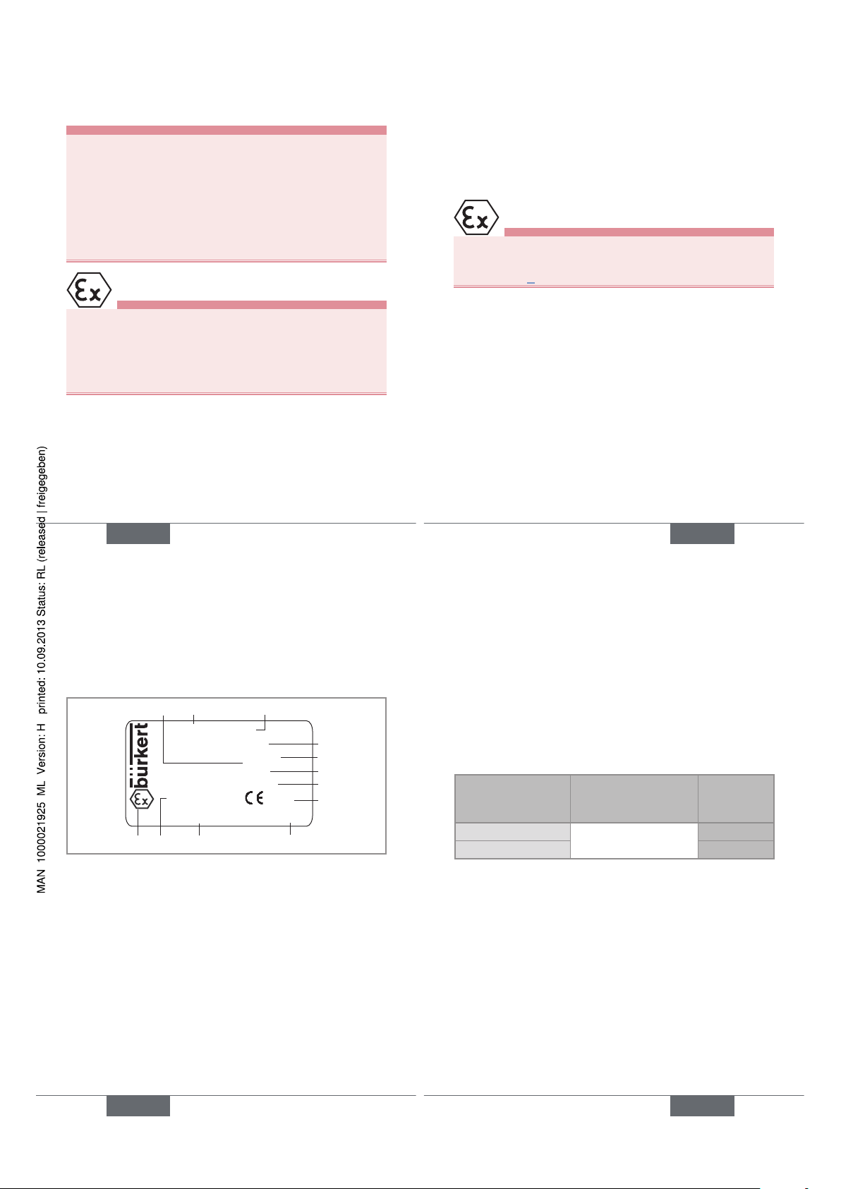
Description of the name plate
SE30EX-NAMUR
II 1 G/D Ex ia IIC T6
Ex iaD 20 IP6X T80°C
Tamb : 0°C - +60°C
LCIE 04 ATEX 6070 X
S/N:1000
00552901 W46LN
F-67220 TRIEMBACH
13
5
7
11 9
6
10
4
12
0102
2
8
1. Protection rating
2. Type of flowmeter
3. Type of supply/output
4. ATEX classification
5. Maximum surface temperature
6. Ambient operating temperature
7. Certification body and ATEX number
8. CE logo and code of notified body that inspected the site
9. Manufacturing code and manufacturing year code
10. Order code
11. Serial number
12. Ex logo
English
19
Available versions of the
electronic flowmeter SE30 Ex
All the versions of the SE30 Ex flowmeter:
• are energized through an intrinsic safety barrier ;
• have a Namur output.
Version of the
SE30 Ex electronic
flowmeter
Electrical connection Order code
Namur II 1 G/D Male fixed connector
EN 175301-803
552901
NamurI M 1 553455
English
19
Page 6
20
8. TECHNICAL DATA
Conditions of use
Ambient temperature
(operating)
0 °C to +60 °C
Air humidity < 80%, non condensated
Protection rating IP 67 acc. to EN60529,
connector plugged-in and cable
gland tightened
General data
Pipe diameter
• with S030 fitting
• with S070 fitting
DN6 to DN65
DN15 to DN50
Fluid temperature 80 °C max.
Flow rate measuring
range with S030
fitting
0,3 to 10 m/s
Flow rate measuring
range with S070
fitting
• viscosity > 5 cps
• viscosity < 5 cps
• 2 to 350 l/min
• 3 to 300 l/min
English
21
Accuracy • ±0,5 % of the full scale *, with
calibration on site (e.g., using
Teach-in feature of a transmitter
8025, remote version)
• ± 0,5 % of the full scale + 2,5 %
of the measured value*, with
standard K factor
Linearity ≤ ± 0,5 % of the full scale *
Repeatability ± 0,4 % of the measured value *
* Determined in the following reference conditions: medium =
water, water and ambient temperatures 20 °C, min. upstream and
downstream distances respected, appropriate pipe dimensions
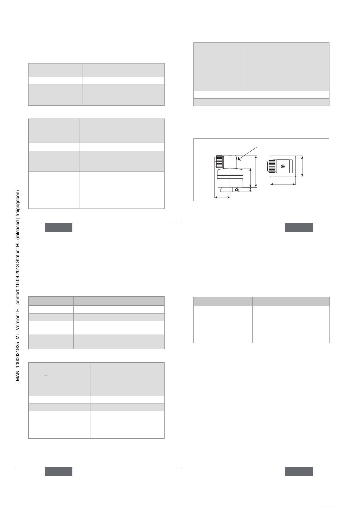
Dimensions
32
40
66
44
54
9
2508 female
connector
Fig. 1 : Dimensions [mm] of the SE30 Ex electronic module
English
21
22
Materials
Part Material
Housing, cover PPS, glass fibre reinforced
Connector PA, with silicone seal
Fitting S030 refer to the operating instructions of
the fitting used.
Fitting S070 refer to the operating instructions of
the fitting used.
Electrical data
Power supply: see
chap. 6 to choose the
appropriate power
supply according to the
place of use
I M1 or II 1 G/D version:
supplied by the intrinsic safety
barrier with NAMUR input
(DIN 60947-5-6)
Current consumption 7 mA max.
Reversed polarity protected
Output signal 0.5 or 2.5 mA, through
both supply wires, current
modulation according to
NAMUR standard
English
23
Electrical connection
Type of connector Cable type
Female connector type
2508 (supplied), with
order code 167526
• shielded, max. 50 m
• 5 to 8 mm in diameter
• wires with cross section
between 0.5 and 1.5 mm
2
,
line impedance < 50 Ω
English
23
Page 7
24
9. INSTALLATION AND
COMMISSIONING
Safety instructions
danger
Risk of injury due to high pressure in the installation.
• Stop the circulation of fluid, cut off the pressure and drain
the pipe before loosening the process connections.
Risk of injury due to high fluid temperatures.
• Use safety gloves to handle the device.
• Stop the circulation of fluid and drain the pipe before
loosening the process connections.
Risk of injury due to the nature of the fluid.
• Respect the prevailing regulations on accident prevention
and safety relating to the use of hazardous products.
danger
Risk of injury due to electrical voltage.
• Shut down the electrical power source of all the
conductors and isolate it before carrying out work on
the system.
• Observe all applicable accident protection and safety
regulations for electrical equipment.
English
25
Warning
Risk of injury due to non-conforming installation.
• The electrical and fluid installation can only be carried out
by qualified and skilled staff with the appropriate tools.
• Observe mounting instructions of the fitting.
Risk of injury due to an uncontrolled restart.
• Ensure that the restart of the installation is controlled
after any interventions on it.
Warning
Risk of injury due to non-conforming commissioning.
Non conforming commissioning may lead to injuries and
damage the device and its surroundings.
• Before commissioning, make sure that the staff in
charge have read and fully understood the contents of
the operating instructions.
• In particular, observe the safety recommendations and
intended use.
• The device / the installation must only be commissioned by suitably trained staff.
English
25
26
note
Risk of damage to the device due to the environment
• Protect this device against electromagnetic interference, ultraviolet rays and, when installed outdoors, the
effects of the climatic conditions.
To make sure the device operates correctly, plug in
and tighten the female connector.
Installation onto the pipe
atex
Use only brass, stainless steel, aluminium or PVDF fittings. Any other fittings are prohibited in explosive areas.
In firedamp mines use brass or stainless steel fittings
only, with a PVDF paddle-wheel for an S030 fitting.
Comply with the safety instructions and the "ATEX instructions notice" (chap. 6) for the type of fluid connection
that can be used depending on the place of installation
in potentially explosive atmospheres.
→ When installing the device, respect the instructions of
the S030 or S070 fittings operating instructions.
English
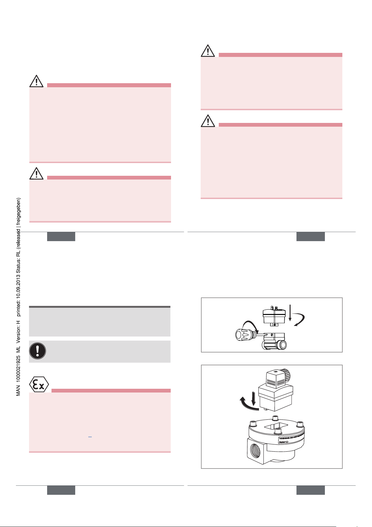
27
1
2
3
Fig. 2 : Mounting of the SE30 Ex onto an S030 fitting
1
2
Fig. 3 : Mounting of the SE30 Ex onto an S070 fitting
English
27
Page 8
28
10. WIRING
danger
Risk of injury due to electrical discharge
• Shut down the electrical power source of all the
conductors and isolate it before carrying out work on
the system.
• Observe all applicable accident protection and safety
regulations for electrical equipment.
Protect the power supply
• Protect the power supply with a correctly rated
fuse if it is not protected by default.
• Use a shielded cable with an operating temperature limit higher than +80 °C.
• Use a high quality electrical power supply (filtered and regulated).
1
2
3
1: V+ (12-36 V DC)
2: not connected
3: L- ( 0 V DC)
: Functional earth
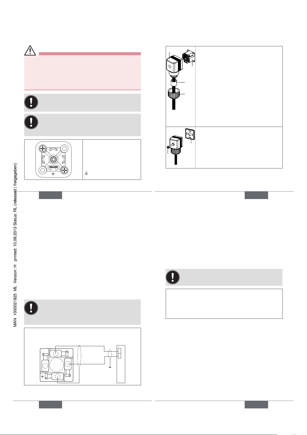
Fig. 4 : Pin assignment of the male fixed connector
English
29
Assembling the female connector
1
2
3
4
→ Unscrew nut [1] of the cable gland.
→ Remove terminal block [3] from
housing [2].
→ Insert the cable into nut [1], through
seal [4], and into the cable gland and
finally through housing [2].
→ Connect the wires on terminal block
[3].
→ Position terminal block [3] in steps of
90° then put it back into housing [2],
pulling gently on the cable so that the
wires do not clutter the housing.
→ Tighten nut [1] of the cable gland.
6
5
→ Place seal [5] between the connector
and the fixed connector on the device
and then plug the 2508 connector into
the fixed connector.
→ Insert and then tighten screw [6] to
ensure tightness and correct electrical
contact.
Fig. 5 : Assembling the female connector type 2508
(supplied)
English
29
30
Wiring of the SE30 Ex, marking II 1
G/D or M1 (with NAMUR intrinsic
safety barrier)
• Use a shielded cable with an operating temperature
suited to the process.
• Use an intrinsic safety barrier with NAMUR input and a
power supply, both complying with the safety instructions
and with the ATEX instructions notice.
• Earth the shielding of the cable on side of the
measuring exploitation.
• Before wiring the device, Plug out the female
connector.
1
3
2
+
-
L+
L-
EN 175301-803 male fixed
connector of the SE30 Ex
Intrinsic safety barrier
Fig. 6 : Wiring the SE30 Ex to an intrinsic safety barrier
English
31
Connection example with the
SE30 Ex and the externally
powered intrinsic safety barrier
Refer to the operation instructions of transmitter 8025
Universal for any other wiring instruction.
Position of 8025 Universal selectors:
• «SENSOR INPUT LOAD» = «1» (2.2 kΩ)
• «FLOW SENSOR» = «NPN/PNP»
• «SENSOR SUPPLY» = indifferent
English
31
Page 9
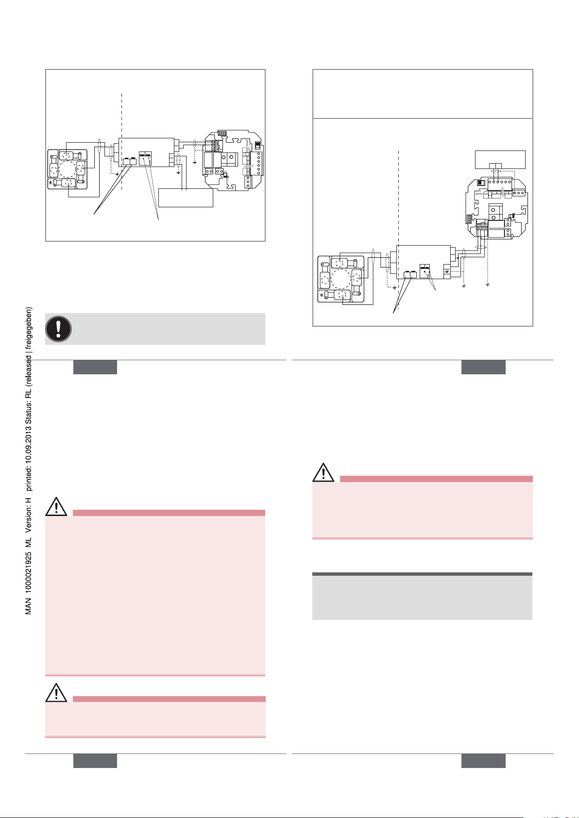
32
→ To access the intrinsic safety barrier switches, remove
the blue mask on the front side.
SE30 Ex
8025 Universal
+
-
L+
L-
+
-
24 VDC ± 10%
/ 230 VAC
B
A
ON
12
1
2
3
CURRENT
SOURCE SINK
BINARY
PE PEPE
PE
DI1
DI2
DI3
DI4
DO4
ISOG
FLOW
SENSOR
L+ L- PE P- P+
NC
Iout
PULSE
DO1
Supply
12..36Vdc
Univ
Batch
(AO1)
SUPPLY
NC
COIL
PULSE
INPUT
NPN/PNP
213PE
+-
SENSOR
SUPPLY
LOAD
+5V
L+
(L+)-12V
COIL/PNP
39K
470
2.2K
SENSOR TYPE
COILNPN/PNP
DO2
DO3
OFF ON
Intrinsic safety
barrier
Potentially explosive
area
Safe area
Power supply
Put the 2 switches "1" and "2" in the ON
position.
The position of switches
"B" and "A" is indifferent.
Fig. 7 : Connection between an SE30 Ex and a panel
version of the transmitter 8025 Universal
Connection example with the SE30 Ex
and the intrinsic safety barrier, 24 VDC,
powered through the transmitter
Refer to the operating instructions of transmitter 8025
Universal for any other wiring instruction.
English
33
Position of 8025 Universal selectors:
• «SENSOR INPUT LOAD» = «1» (2.2 kΩ)
• «FLOW SENSOR» = «NPN/PNP»
• «SENSOR SUPPLY» = «3» (L+)
→ To access the intrinsic safety barrier switches, remove
the blue mask on the front side.
SE30 Ex
8025
Universal
+
-
L+
L-
+
-
24 V DC ± 10%
BA
ON
12
1
2
3
+-
+
-
CURRENT
SOURCESINK
BINARY
PE PEPE
PE
DI1
DI2
DI3
DI4
DO4
ISOG
FLOW
SENSOR
L+ L- PE P- P+
NC
Iout
PULSE
DO1
Supply
12..36Vdc
Univ
Batch
(AO1)
SUPPLY
NC
COIL
PULSE
INPUT
NPN/PNP
213PE
+-
SENSOR
SUPPLYLOAD
+5V
L+
(L+)-12V
COIL/PNP
39K
470
2.2K
SENSOR TYPE
COIL NPN/PNP
DO2
DO3
OFFON
Potentially
explosive area
Safe area
Intrinsic safety
barrier
Power supply
The position of switches "B" and "A" is indifferent.
Put the 2 switches "1" and "2" in
the ON position.
Fig. 8 : Connection between an SE30 Ex and a panel
version of the transmitter 8025 Universal.
English
33
34
11. MAINTENANCE
Safety instructions
danger
Risk of injury due to electrical voltage.
• Shut down the electrical power source of all the conductors and isolate it before carrying out work on the system.
• Observe all applicable accident protection and safety
regulations for electrical equipment.
Risk of injury due to high pressure in the installation.
• Stop the circulation of fluid, cut off the pressure and drain
the pipe before loosening the process connections.
Risk of injury due to high fluid temperatures.
• Use safety gloves to handle the device.
• Stop the circulation of fluid and drain the pipe before
loosening the process connections.
• Keep all easily flammable material and fluid away from
the device.
danger
Risk of injury due to the nature of the fluid.
• Respect the prevailing regulations on accident prevention and safety relating to the use of aggressive fluids.
English
35
Warning
Risk of injury due to non-conforming maintenance.
• Maintenance must only be carried out by qualified and
skilled staff with the appropriate tools.
• Ensure that the restart of the installation is controlled
after any interventions.
Cleaning
note
The device may be damaged by the cleaning liquid.
• Clean the device with a cloth slightly dampened with
water or a cleaning liquid compatible with the materials
the device is made of.
English
35
Page 10

36
12. ACCESSORIES
attention
Risk of injury and/or damage caused by the use of
unsuitable parts.
Incorrect accessories and unsuitable spare parts may
cause injuries and damage the device and the surrounding area.
• Use only original accessories and original spare parts
from Bürkert.
Accessories Order code
EN 175301-803 female connector (type
2508) with blue cable gland and silicone
seal
167526
Mechanical protection for SE30 Ex
"Namur I M1"
553519
Intrinsic safety barriers, voltage supply
24 V DC, open collector output, 15 V,
60 mA:
• 2 channels with dry or Namur contact
inputs
553456
• 4 channels with dry or Namur contact
inputs
553457
English
37
Accessories Order code
Intrinsic safety barriers, voltage supply
230 V AC, open collector output, 15 V,
60 mA:
• 2 channels with dry or Namur contact
inputs
553458
• 4 channels with dry or Namur contact
inputs
553459
13. PACKAGING, TRANSPORT
attention
Damage due to transport
Transport may damage an insufficiently protected device.
• Transport the device in shock-resistant packaging and
away from humidity and dirt.
• Do not expose the device to temperatures that may
exceed the admissible storage temperature range.
• Protect the electrical interfaces using protective plugs.
English
37
38
14. STORAGE
attention
Poor storage can damage the device.
• Store the device in a dry place away from dust.
• Storage temperature: 0 to +60°C.
15. DISPOSAL OF THE DEVICE
→ Dispose of the device and its packaging in an environ-
mentally-friendly way.
note
Damage to the environment caused by products
contaminated by fluids.
• Keep to the existing provisions on the subject of waste
disposal and environmental protection.
Note
Comply with the national and/or local regulations
which concern the area of waste disposal.
English
39
English
39
Page 11

Typ SE30 EX
Elektronisches Durchflussmessgerät für
explosionsgefährdeten Bereich
Bedienungsanleitung
Deutsch
2
1. DIE BEDIENUNGSANLEITUNG .........................................3
2. BESTIMMUNGSGEMÄSSE VERWENDUNG................5
3. GRUNDLEGENDE SICHERHEITSHINWEISE ..............6
4. ALLGEMEINE HINWEISE .......................................................9
5. KONFORMITÄTSERKLÄRUNG ......................................... 10
6. ATEX-BEDIENUNGSANLEITUNG ........................................... 12
7. BESCHREIBUNG .................................................................... 18
8. TECHNISCHE DATEN ..........................................................21
9. INSTALLATION UND INBETRIEBNAHME .................. 25
10. VERKABELUNG ....................................................................... 30
11. WARTUNG .................................................................................. 36
12. ZUBEHÖR .................................................................................. 38
13. VERPACKUNG, TRANSPORT ........................................... 39
14. LAGERUNG ................................................................................ 40
15. ENTSORGUNG DES GERÄTES ......................................40
deutsch
3
1. DIE BEDIENUNGSANLEITUNG
Die Bedienungsanleitung beschreibt den gesamten Lebenszyklus des Gerätes. Bewahren Sie diese Anleitung so auf,
dass sie für jeden Benutzer zugänglich ist und jedem neuen
Eigentümer des Gerätes wieder zur Verfügung steht.
Diese Bedienungsanleitung enthält wichtige Informationen zur Sicherheit!
Das Nichtbeachten dieser Hinweise kann zu gefährlichen
Situationen führen.
• Diese Bedienungsanleitung muss gelesen und verstanden werden.
Darstellungsmittel
Gefahr!
Warnt vor einer unmittelbaren Gefahr!
• Bei Nichteinhaltung sind Tod oder schwere Verletzungen die Folge.
WarnunG!
Warnt vor einer möglicherweise gefährlichen
Situation!
• Bei Nichteinhaltung drohen schwere Verletzungen oder Tod.
deutsch
4
VOrSIChT!
Warnt vor einer möglichen Gefährdung!
• Nichtbeachtung kann mittelschwere oder leichte Verletzungen zur Folge haben.
aTex
Weist auf eine wichtige Information oder einen ATEX
Sicherheitshinweis hin.
hInWeIS!
Warnt vor Sachschäden!
• Bei Nichtbeachtung kann das Gerät oder die Anlage
beschädigt werden.
bezeichnet wichtige Zusatzinformationen, Tipps
und Empfehlungen.
verweist auf Informationen in dieser Bedienungsanleitung oder in anderen Dokumentationen.
→ markiert einen Arbeitsschritt, den Sie ausführen müssen.
Begriffsdefinition "Gerät"
Der in dieser Anleitung verwendete Begriff "Gerät" steht immer
für das elektronische Durchfluss-Messgerät Typ SE30 Ex.
deutsch
Page 12

5
2. BESTIMMUNGSGEMÄSSE
VERWENDUNG
Bei nicht bestimmungsgemäßem Einsatz dieses
Gerätes können Gefahren für Personen, Anlagen in
der Umgebung und die Umwelt entstehen.
• Das elektronische Durchfluss-Messgerät SE30 Ex
dient zur Durchflussmessung von neutralen bzw. leicht
aggressiven Flüssigkeiten ohne Feststoffpartikeln in
explosionsgefährdeten Bereichen (siehe Kap. 6).
• Schützen Sie das Gerät vor elektromagnetischen Störungen, U.V.-Bestrahlung und bei Außenanwendung
vor Witterungseinflüssen.
• Für den Einsatz sind die in den Vertragsdokumenten
und der Bedienungsanleitung spezifizierten zulässigen Daten, Betriebs- und Einsatzbedingungen zu
beachten.
• Zum sicheren und problemlosen Einsatz des Gerätes
müssen Transport, Lagerung und Installation ordnungsgemäß erfolgen, außerdem müssen Betrieb und
Wartung sorgfältig durchgeführt werden.
• Achten Sie immer darauf, dieses Gerät auf ordnungsgemäße Weise zu verwenden.
→ Beachten Sie bei der Ausfuhr des Gerätes gegebenen-
falls bestehende Beschränkungen.
deutsch
6
3. GRUNDLEGENDE
SICHERHEITSHINWEISE
Diese Sicherheitshinweise berücksichtigen keine
• Zufälligkeiten und Ereignisse, die bei Montage, Betrieb und
Wartung der Geräte auftreten können.
• Ortsbezogenen Sicherheitsbestimmungen, für deren
Einhaltung, auch in Bezug auf das Installations- und Wartungspersonal, der Betreiber verantwortlich ist.
Gefahr durch hohen Druck in der Anlage!
Gefahr durch elektrische Spannung!
Gefahr durch hohe Flüssigkeitstemperaturen!
Gefahr aufgrund der Art der Flüssigkeit!
Allgemeine Gefahrensituationen.
Zum Schutz vor Verletzungen ist zu beachten
• Die Anlage nicht unbeabsichtigt betätigen.
• Installations- und Instandhaltungsarbeiten dürfen
nur von autorisiertem Fachpersonal mit geeignetem
Werkzeug ausgeführt werden.
deutsch
7
Allgemeine Gefahrensituationen.
Zum Schutz vor Verletzungen ist zu beachten
• Nach einer Unterbrechung der elektrischen Versorgung ist ein definierter oder kontrollierter Wiederanlauf
des Prozesses zu gewährleisten.
• Betreiben Sie das Gerät nur in einwandfreiem Zustand
und unter Beachtung der Bedienungsanleitung.
• Bei der Einsatzplanung und dem Betrieb des Fittings
die allgemeinen Regeln der Technik einhalten.
• Dieses Gerät nicht für die Durchflussmessung von Gas
einsetzen.
• Keine Flüssigkeit verwenden, die sich nicht mit den Werkstoffen verträgt, aus denen das Gerät besteht.
• Dieses Gerät nicht in einer Umgebung verwenden, die mit
den Materialien, aus denen es besteht, inkompatibel ist.
• Belasten Sie das Gerät nicht mechanisch (z. B. durch
Ablage von Gegenständen oder als Trittstufe).
• Keine innerlichen oder äußerlichen Veränderungen am
Gerät vornehmen.
deutsch
8
hInWeIS!
Das Gerät kann durch das Medium beschädigt
werden.
• Kontrollieren Sie systematisch die chemische Verträglichkeit der Werkstoffe, aus denen das Gerät besteht,
und der Flüssigkeiten, die mit diesem in Berührung
kommen können (zum Beispiel: Alkohole, starke oder
konzentrierte Säuren, Aldehyde, Basen, Ester, aliphatische Verbindungen, Ketone, aromatische oder
halogenierte Kohlenwasserstoffe, Oxidations- und
chlorhaltige Mittel).
deutsch
Page 13

9
4. ALLGEMEINE HINWEISE
Sie können mit dem Hersteller des Gerätes unter folgender
Adresse Kontakt aufnehmen:
Bürkert SAS
Rue du Giessen
BP 21
F-67220 TRIEMBACH-AU-VAL
Die internationalen Kontaktadressen finden Sie im Internet
unter: www.burkert.com
Informationen im Internet
Bedienungsanleitungen und Datenblätter zum Typ SE30
finden Sie im Internet unter: www.buerkert.de
deutsch
10
5. KONFORMITÄTSERKLÄRUNG
Hiermit erklären wir, die Firma Bürkert, als Hersteller, dass
das nachstehend bezeichnete Produkt:
ELEKTRONISCHES DURCHFLUSS-MESSGERÄT
Typ SE30 Ex
mit folgender Kennzeichnung: II 1 G/D oder I M1, folgende
Anforderungen erfüllt:
• der Richtlinie 94/9/EG für Geräte zur bestimmungsgemäßen Verwendung in explosionsgefährdeten Bereichen.
Die Bewertung erfolgte an Hand folgender Normen:
- EN 60079-0 (2006)
- EN 60079-11 (2007)
- EN 61241-0 (2004)
- EN 61241-11 (2007)
• der Richtlinie 2004/108/EEG Elektromagnetische Verträglichkeit. Die Bewertung erfolgte an Hand folgender
Normen:
- Störstrahlung gemäß EN 61000-6-3 (2007)
- Störfestigkeit gemäß EN 61000-6-2 (2005)
Die EG-Baumuster-Prüfbescheinigung LCIE 04 ATEX
6070 X (siehe Anhang) wurde erstellt durch LCIE (Laboratoire Central des Industries Electriques, 33 avenue du G
al
Leclerc, BP 8, F-92266 Fontenay-aux-Roses).
deutsch
11
Vorbehaltlich der bestimmungsgemäßen Verwendung und/
oder der Installation im Einklang mit den einschlägigen
Normen und/oder den Empfehlungen des Herstellers und
der Berücksichtigung der besonderen Bedingungen für den
sicheren Gebrauch gemäß der EG-Baumusterprüfbescheinigung. Siehe Kap. 6 dieser Bedienungsanleitung.
Der Bewertungsbescheid des Qualitätsmanagementsystems Nr. PTB 98 ATEX Q008-2 wurde durch die PTB
(Physikalisch-Technische Bundes-anstalt, Bundesallee
100, D-38116 BRAUNSCHWEIG) erteilt.
Triembach-au-Val, den 18/02/2010 Qualitätssicherung
Bürkert S.A.S Bruno Thouvenin
Rue du Giessen
F-67220 Triembach-au-Val
deutsch
12
6. ATEX-BEDIENUNGSANLEITUNG
Vorgesehener Einsatzbereich
Das Durchfluss-Messgerät SE30 Ex dient zur Durchflussmessung von neutralen bzw. leicht aggressiven Flüssigkeiten ohne Feststoffpartikeln in folgenden explosionsgefährdeten Bereichen:
• Zonen 0, 1 oder 2 sowie 20, 21, 22, Geräte der Kategorien II 1 G/D
• Schlagwettergefährdete Grubenbereiche, Geräte der
Kategorie I M1
Modell SE30 Ex NAMUR, Bestell-Nr. 552901, für gasexplosionsgefährdete Bereiche (Zonen 0, 1 und 2) und
staubexplosionsgefährdete Bereiche (Zonen 20, 21
und 22)
• Erläuterungen zur Kennzeichnung und zur Installation:
CE 0102
II 1 GD
Ex ia IIC T6
Ex iaD 20 IP6X T80°C
Umgebungstemperatur: 0°C ≤ Ta ≤
60°C
LCIE 04 ATEX 6070 X
• Besondere Bedingungen für den sicheren Gebrauch:
- Das Gerät ist mit einer Eigensicherheit versehen.
deutsch
Page 14

13
- Es darf in explosionsgefährdeten Bereichen eingesetzt
werden: Zonen 0, 1 oder 2 bzw. Zonen 20, 21 oder
22.
- Der Stecker darf nur an zertifizierte Geräte mit Eigensicherheit angeschlossen werden. Diese Steckverbindungen müssen im Hinblick auf die Eigensicherheit
des Gerätes kompatibel sein und haben nachstehenden Parametern Rechnung zu tragen.
- Umgebungstemperatur im Betrieb: 0 °C bis +60 °C
• Spezifische Parameter der betreffenden Schutzart(en):
Ui ≤ 15V, Ii ≤ 50 mA, Pi ≤ 188 mW, Ci ≤ 1,2 nF, Li ≅ 0
• Mit dieser Kennzeichnung und mit dieser Verwendung
kompatible mechanische Montagearten und Medienanschlüsse:
Es sind ausschließlich Anschlüsse aus Messing, Edelstahl,
Aluminium oder PVDF.
Bei einem Fitting mit Flügelrad aus PP vergewissern
Sie sich, dass keine Explosionsgefahr innerhalb der
Rohrleitung besteht: Der fluidische Teil muss sich
außerhalb der ATEX-Zone befinden.
• Andersartige Fittings sind in explosionsgefährdeten
Bereichen untersagt.
deutsch
14
Modell SE30 Ex NAMUR, Bestell-Nr. 553455, für
schlagwettergefährdete Grubenbereiche
• Erläuterungen zur Kennzeichnung und zur Installation
CE 0102
I M1
Ex ia I T80°C
Umgebungstemperatur: 0°C ≤ Ta ≤
60°C
LCIE 04 ATEX 6070 X
• Besondere Bedingungen für den sicheren Gebrauch:
- Eigensicheres Gerät für schlagwettergefährdete
Grubenbereiche.
- Es darf in explosionsgefährdeten Bereichen eingesetzt werden:Bergbau.
- Der Stecker darf nur an zertifizierte Geräte mit Eigensicherheit angeschlossen werden. Diese Steckverbindungen müssen im Hinblick auf die Eigensicherheit
des Gerätes kompatibel sein und haben nachstehenden Parametern Rechnung zu tragen.
- Umgebungstemperatur im Betrieb: 0 °C bis +60 °C
• Spezifische Parameter der betreffenden Schutzart(en):
Ui ≤ 15V, Ii ≤ 50 mA, Pi ≤ 188 mW, Ci ≤ 1,2 nF, Li ≅ 0
• Mit dieser Kennzeichnung und mit dieser Verwendung
kompatible mechanische Montagearten und Medienanschlüsse:
Es sind ausschließlich Fittings aus Messing oder Edel-
deutsch
15
stahl und, bei einem S030 Fitting, mit PVDF-Flügelrad zu
verwenden.
- Andersartige Anschlüsse sind untersagt.
- Das Gerät ist gegen mechanische Beschädigungen
zu schützen. Die mechanische Schutzvorrichtung mit
Bestell-Nr. 553519 verwenden.
Gewährleistung und Haftung
Während und nach Ablauf der Gewährleistungsfrist ist
einzig die Firma Bürkert dazu befugt, Reparaturen bzw.
Umbauten an denjenigen ihrer Produkte vorzunehmen, die
den Gegenstand einer EG-Baumusterprüfbescheinigung
gebildet haben. Bürkert haftet nicht im Falle der Missachtung dieser Klausel.
Die Montagearbeiten sind durch entsprechend qualifizierte Fachkräfte vorzunehmen. Bei Schwierigkeiten während der Installation bzw. der Inbetriebnahme ist umgehend mit Ihrem Bürkert-Lieferanten
Kontakt aufzunehmen.
Rückverfolgbarkeit
Die Produkte der Baureihe SE30 Ex sind an Hand einer
individuellen Seriennummer gekennzeichnet, die der Rückverfolgbarkeit dient. Diese (5-stellige) Zahl in Verbund
mit dem Baujahr befindet sich auf dem Typschild mit der
Bestell-Nummer des Gerätes.
deutsch
16
Bei diesem Produkt handelt es sich um ein Gerät für
explosionsgefährdete Bereiche. Diesbezüglich und unter
Berücksichtigung der ATEX-Richtlinie 94/9/EG sind spezifische Vorkehrungen zu treffen, um die Rückverfolgbarkeit
des Gerätes im vor- und nachgeschalteten Bereich sicherzustellen.Unser mit ATEX-Bescheid zertifiziertes QMSystem gewährleistet diese Rückverfolgbarkeit bis zum Ort
der ersten Auslieferung.
Ausgenommen im Falle gegenteilig lautender vertraglicher
Bestimmungen sind alle Personen, die diese Geräte weiterliefern, dazu verpflichtet, ein System einzuführen, das
eine eventuell erforderliche Rückrufaktion für fehlerhafte
Geräte ermöglicht.
Vorsichtsmaßnahmen bei
Installation
Bei nicht bestimmungsgemäßem Einsatz dieses
Gerätes können Gefahren für Personen, Anlagen in
der Umgebung und die Umwelt entstehen.
• Schützen Sie das Gerät vor elektromagnetischen Störungen, U.V.-Bestrahlung und bei Außenanwendung
vor Witterungseinflüssen.
• Beim Ausbau des Durchfluss-Messgerätes aus der
Rohrleitung sind alle verfahrenstechnisch gebotenen
Sicherheitsmaßnahmen zu treffen.
deutsch
Page 15

17
aTex
Dieses Gerät ist nach Maßgabe der Bestimmungen der
Norm EN 60079-14 zu installieren: Elektrische Betriebsmittel für gas-explosionsgefährdete Bereiche.
Teil 14: Elektrische Anlagen für gefährdete Bereiche
(ausgenommen Grubenbaue).
deutsch
18
7. BESCHREIBUNG
Aufbau
Das Durchfluss-Messgerät SE30 Ex ist ein Elektronikmodul,
das auf ein Messelement, entweder Fitting S030 (aus
Messing, Edelstahl oder PVDF) oder S070, aufgebaut wird.
aTex
Entsprechend des Einsatzortes ist das Durchfluss-Messgerät
SE30 Ex gemäß den Angaben des Kap. 6 anzuschließen.
Der elektrische Anschluss erfolgt über einen EN 175301-803
Gerätestecker.
Messprinzip
Der Sensor spürt die Rotationsbewegung des Flügelrads
auf und moduliert den Strom der Versorgungsleitung gemäß
Namur-Norm (0,5 mA oder 2,5 mA). Die Modulationsfrequenz f verhält sich proportional zum Durchfluss Q gemäß
der Formel f = K x Q.
f = Frequenz in Hz
K = fittingspezifischer K-Faktor, in Impulsen/Liter
Q = Durchfluss in l/s
Um dieses Signal auswerten zu können, ist eine Eigensicher-
heitsbarriere vom Typ Namur an den SE30 Ex anzuschließen.
Diese spürt die Modulation auf und wandelt sie an ihrem
deutsch
19
Ausgang mit offenem Kollektor in eine Frequenz um.
Beschreibung des Typschilds
SE30EX-NAMUR
II 1 G/D Ex ia IIC T6
Ex iaD 20 IP6X T80°C
Tamb : 0°C - +60°C
LCIE 04 ATEX 6070 X
S/N:1000
00552901 W46LN
F-67220 TRIEMBACH
13
5
7
11 9
6
10
4
12
0102
2
8
1. Schutzart
2. Typ des
DurchflussMessgerätes
3. Art der Ver-
sorgungsspannung /
Ausgangsart
4. ATEX-Klassifizierung
5. Maximale Oberflächentemperatur
6. Betriebsumgebungstemperatur
7. Zertifizierungsstelle und ATEX-Nummer
8. CE-Zeichen und Kennnummer der benannten Stelle,
die das Audit des Herstellerwerks durchgeführt hat
9. Herstellungscode und Baujahrcode
10. Bestellnummer
11. Seriennummer
12. Ex-Symbol
deutsch
20
Verfügbare Versionen des
Elektronikmoduls SE30 Ex
Alle Versionen des Durchfluss-Mesgerätes SE30 Ex
• werden über eine Eigensicherheitsbarriere mit Strom
versorgt,
• haben einen Namur-Ausgang.
Version des elektronischen Durchfluss-
Messgerätes SE30 Ex
Elektrischer
Anschluss
Bestell-
nummer
Namur II 1 G/D EN 175301-803
Gerätestecker
552901
Namur I M 1 553455
deutsch
Page 16

21
8. TECHNISCHE DATEN
Betriebsbedingungen
Umgebungstemperatur
(im Betrieb)
0 °C bis +60 °C
Luftfeuchtigkeit < 80%, nicht kondensierend
Schutzart IP67 nach EN60529, mit ein-
gesteckter Buchse und festgeschraubter Kabelverschraubung
Allgemeine Daten
Durchmesser der
Rohrleitung
• mit Fitting S030
• mit Fitting S070
• DN6 bis DN65
• DN6 bis DN50
Flüssigkeitstemperatur
max. 80 °C
Messbereich des
Durchflusses mit
Fitting S030
0,3 bis 10 m/s
deutsch
22
Messbereich des
Durchflusses mit
Fitting S070
• Viskosität > 5 cps
• Viskosität < 5 cps
• 2 bis 350 l/min
• 3 bis 300 l/min
Genauigkeit • ±0,5 % vom Messbereichsende*,
mit Kalibrierung vor Ort (zum Beispiel mittels der Funktion Teach-In
eines abgesetzten Transmitters
Typ 8025)
• ± 0,5 % vom Messbereichsende*
+ 2,5% vom Messwert, mit
K-Faktor des Fittings
Linearität ≤ ± 0,5 % des Messbereichsendes *
Wiederholbarkeit ± 0,4 % des Messwertes*
* Unter folgenden Referenzbedingungen bestimmt: Flüssigkeit =
Wasser, Wasser- und Umgebungstemperatur von 20 °C, Berücksichtigung der Mindestein- und -auslaufstrecken, angepasste
Rohrleitungsabmessungen.
deutsch
23
Abmessungen
32
40
66
44
54
9
Buchse Typ 2508
Bild 1: Abmessungen [mm] des Elektronikmoduls SE30 Ex
Werkstoffe
Teil Werkstoff
Gehäuse, Deckel PPS, glasfaserverstärkt
Buchse: PA mit Dichtung aus Silikon
Fitting S030 Siehe die Bedienungsanleitung des
verwendeten Fittings.
Fitting S070 Siehe die Bedienungsanleitung des
verwendeten Fittings.
deutsch
24
Elektrische Daten
Für die
Spannungsversorgung:
Siehe Kap. 6, um
eine geeignete
Stromversorgung
gegenüber des
Verwendungsorts
einzusetzen
Version I M1 oder II 1 G/D:
durch Eigensicherheitsbarriere
mit NAMUR-Eingang (DIN
60947-5-6)
Stromaufnahme max. 7 mA
Schutz gegen Verpolung ja
Transistor-Ausgang (Hall
Low Power-Version)
0,5 oder 2,5 mA, durch
beide Versorgungsdrahte,
Strommodulation nach
NAMUR
Elektrischer Anschluss
Typ des Anschlusses Kabeltyp
Buchse Typ 2508
(mitgeliefert), mit
Bestell-Nummer
167526
• abgeschirmt, max. 50 m
• mit 5 bis 8 mm-Durchmesser
• mit Adern mit Querschnitt
zwischen 0,5 und 0,5 et
1,5 mm
2
, Kabelimpedanz <
50 Ω
deutsch
Page 17

25
9. INSTALLATION UND
INBETRIEBNAHME
Sicherheitshinweise
Gefahr!
Verletzungsgefahr durch hohen Druck in der Anlage!
• Vor dem Lösen der Prozessanschlüsse die Anlage
druckfrei schalten und die Flüssigkeitszirkulation
stoppen.
Verletzungsgefahr durch hohe
Flüssigkeitstemperaturen!
• Das Gerät nur mit Schutzhandschuhen anfassen.
• Vor dem Lösen der Prozessanschlüsse die Flüssigkeitszirkulation stoppen und die Rohrleitung leeren.
Verletzungsgefahr aufgrund der Art der Flüssigkeit!
• Beachten Sie die Regeln, die auf dem Gebiet der
Unfallverhütung und der Sicherheit in Kraft sind und
die sich auf die Verwendung gefährlicher Produkte
beziehen.
deutsch
26
Gefahr!
Verletzungsgefahr durch Stromschlag!
• Schalten Sie vor Beginn der Arbeiten in jedem Fall alle
existierenden am Gerät angeschlossenen SpannungsVersorgungen ab, und sichern Sie diese vor unbeabsichtigtem Wiedereinschalten!
• Beachten Sie geltende Unfallverhütungs- und Sicherheitsbestimmungen für elektrische Geräte!
WarnunG!
Verletzungsgefahr bei unsachgemäßer Installation!
• Fluidische und elektrische Installationen dürfen nur
durch autorisiertes Fachpersonal und mit geeignetem
Werkzeug durchgeführt werden!
• Die Installationshinweise des Fittings beachten.
Verletzungsgefahr durch unkontrollierten Wiederanlauf!
• Nach jedem Eingriff an der Anlage einen kontrollierten
Wiederanlauf gewährleisten.
deutsch
27
WarnunG!
Verletzungsgefahr bei unsachgemäßer
Inbetriebnahme!
Nicht sachgemäßer Betrieb kann zu Verletzungen sowie
Schäden am Gerät und seiner Umgebung führen.
• Vor der Inbetriebnahme muss gewährleistet sein, dass
der Inhalt der Bedienungsanleitung dem Bedienungspersonal bekannt ist und vollständig verstanden wurde.
• Besonders zu beachten sind die Sicherheitshinweise
und die bestimmungsgemäße Verwendung.
• Das Gerät/die Anlage darf nur durch ausreichend
geschultes Personal in Betrieb genommen werden.
hInWeIS!
Gefahr der Beschädigung des Gerätes durch die
Umgebung!
• Schützen Sie das Gerät vor elektromagnetischen Störungen, U.V.-Bestrahlung und bei Außenanwendung
vor Witterungseinflüssen.
Um den einwandfreien Betrieb des Gerätes
zu gewährleisten, die Buchse einstecken und
festschrauben.
deutsch
28
Fluidischer Anschluss
aTex
Ausschließlich Fittings aus Messing, Edelstahl, Aluminium oder PVDF verwenden. Andersartige Fittings
sind in explosionsgefährdeten Bereichen untersagt.
In Schlagwettergefährdete Grubenbereiche ausschließlich Fittings aus Messing oder Edelstahl und,
bei einem S030 Fitting, mit PVDF-Flügelrad verwenden.
Beachten Sie die „Sicherheithinweise – ATEX
Bedienungsanleitung» für die je nach Einbauort in
explosionsgefährdeten Bereichen zu verwendenden
Medienanschlussarten.
→ bei der Installation die Montagehinweise des Fittings
S030 oder S070 berücksichtigen.
1
2
3
Bild 2: Montage des SE30 Ex auf ein Fitting S030
deutsch
Page 18

29
1
2
Bild 3: Montage des SE30 Ex auf ein Fitting S070
deutsch
30
10. VERKABELUNG
Gefahr!
Verletzungsgefahr durch Stromschlag!
• Schalten Sie vor Beginn der Arbeiten in jedem Fall alle
existierenden am Gerät angeschlossenen SpannungsVersorgungen ab, und sichern Sie diese vor unbeabsichtigtem Wiedereinschalten!
• Beachten Sie geltende Unfallverhütungs- und Sicherheitsbestimmungen für elektrische Geräte!
Die Spannungsversorgung absichern!
• Die Stromversorgung mit einer ordnungsgemäß
dimensionierte Sicherung absichern, wenn sie
noch nicht entsprechend abgesichert ist.
• Ein abgeschirmtes Kabel mit einer zulässigen Betriebstemperatur von mindestens +80 °C verwenden.
• Eine hochwertige (gefilterte und geregelte)
Stromversorgung verwenden.
1
2
3
1: V+ (12-36 V DC)
2: Nicht belegt
3: L- ( 0 V DC)
: Funktionelle Erde
Bild 4: Steckerbelegung des Gerätesteckers
deutsch
31
Buchse montieren
1
2
3
4
→ Überwurfmutter [1] der Kabelver-
schraubung aufschrauben.
→ Die Schraubklemmleiste [3] aus dem
Gehäuse [2] herausnehmen.
→ Das Kabel durch die Überwurfmutter
[1] dann durch die Dichtung [4] und
die Kabelverschraubung führen und
schließlich in das Gehäuse [2] stecken.
→ Die Anschlüsse an der Schraubklemm-
leiste [3] vornehmen.
→ Die Klemmleiste [3] wie gewünscht
in Schritten von 90° positionieren
und dann wieder in das Gehäuse
[2] einsetzen, indem leicht am Kabel
gezogen wird, um die Leitungslänge im
Gehäuse zu minimieren.
→ Überwurfmutter [1] der Kabelver-
schraubung festschrauben.
deutsch
32
6
5
→ Die Dichtung [5] zwischen die Buchse
und den Gerätestecker einlegen und
dann die Buchse Typ 2508 in den
Gerätestecker stecken.
→ Die Schraube [6] einstecken und
festschrauben, um die Dichtheit und
einen ordnungsgemäßen elektrischen
Kontakt sicherzustellen.
Bild 5: Montage der Buchse Typ 2508 (mitgeliefert)
Verkabelung des SE30 Ex,
Version II 1 G/D oder I M1 (über
NAMUR-Sicherheitsbarriere)
• Ein abgeschirmtes Kabel mit einer dem Prozess entsprechenden Betriebsgrenztemperatur verwenden.
• Eine Eigensicherheitsbarriere Typ NAMUR und eine
entsprechende geeignete Versorgungsspannung gemäß
den «Sicherheits- hinweise - ATEX Betriebsanleitung»
verwenden.
• Die Abschirmung des Kabels auf Seite der Signalauswertung erden.
• Vor jeder Arbeit die Buchse ausstecken.
deutsch
Page 19

33
EN 175301-803 Geräte-
stecker des SE30 Ex
Eigensicherheitsbarriere
1
3
2
+
-
L+
L-
Bild 6: Anschluss des SE30 Ex an eine
Eingensicherheitsbarriere
Anschlussbeispiel des SE30 Ex
und eine Eigensicherheitsbarriere
mit externer Stromversorgung
Siehe die Bedienungsanleitung des Transmitters 8025
Universal für weitere Anschlussinformationen des 8025.
Stelle der Auswahlschalter des 8025 Universal:
• «SENSOR INPUT LOAD» = «1» (2.2 kΩ)
• «FLOW SENSOR» = «NPN/PNP»
• «SENSOR SUPPLY» = Beliebige Stelle
deutsch
34
→ Um an die Schalter der Eigensicherheitsbarriere zu
gelangen, blaue Sichtabdeckung auf Vorderseite entfernen.
SE30 Ex
8025 Universal
+
-
L+
L-
+
-
24 VDC ± 10%
/ 230 VAC
B
A
ON
12
1
2
3
CURRENT
SOURCE SINK
BINARY
PE PEPE
PE
DI1
DI2
DI3
DI4
DO4
ISOG
FLOW
SENSOR
L+ L- PE P- P+
NC
Iout
PULSE
DO1
Supply
12..36Vdc
Univ
Batch
(AO1)
SUPPLY
NC
COIL
PULSE
INPUT
NPN/PNP
213PE
+-
SENSOR
SUPPLY
LOAD
+5V
L+
(L+)-12V
COIL/PNP
39K
470
2.2K
SENSOR TYPE
COILNPN/PNP
DO2
DO3
OFF ON
Eingensicherheitsbarriere
Explosionsgefährdeter
Bereich
Außerhalb des Explosionsgefährdeten
Bereichs
Versorgungsspannung
Beide Schalter "1" und "2" auf ON stellen.
Stelle der Schalter "B"
und "A" ist beliebig.
Bild 7: Anschluss des SE30 Ex an ein Transmitter 8025
Universal in der Schaltschrank-Ausführung
Anschlussbeispiel des SE30 Ex und
der durch den Transmitter versorgte
Eigensicherheitsbarriere, 24 V DC
Siehe die Bedienungsanleitung des Transmitters
8025 Universal für weitere Anschlussinformationen
des 8025.
deutsch
35
→ Um an die Schalter der Eigensicherheitsbarriere zu
gelangen, blaue Sichtabdeckung auf Vorderseite entfernen.
SE30 Ex
8025
Universal
+
-
L+
L-
+
-
24 V DC ± 10%
BA
ON
12
1
2
3
+-
+
-
CURRENT
SOURCESINK
BINARY
PE PEPE
PE
DI1
DI2
DI3
DI4
DO4
ISOG
FLOW
SENSOR
L+ L- PE P- P+
NC
Iout
PULSE
DO1
Supply
12..36Vdc
Univ
Batch
(AO1)
SUPPLY
NC
COIL
PULSE
INPUT
NPN/PNP
213PE
+-
SENSOR
SUPPLYLOAD
+5V
L+
(L+)-12V
COIL/PNP
39K
470
2.2K
SENSOR TYPE
COIL NPN/PNP
DO2
DO3
OFFON
Eingensicherheitsbarriere
Explosionsgefährdeter
Bereich
Außerhalb des Explosionsgefährdeten
Bereichs
Versorgungsspannung
Beide Schalter "1" und "2" auf ON
stellen.
Stelle der Schalter "B" und "A" ist beliebig.
Stelle der Auswahlschalter des 8025 Universal:
• «SENSOR INPUT LOAD» = «1» (2.2 kΩ)
• «FLOW SENSOR» = «NPN/PNP»
• «SENSOR SUPPLY» = «3» (L+)
Bild 8: Anschluss des SE30 Ex an ein Transmitter 8025
Universal in der Schaltschrank-Ausführung
deutsch
36
11. WARTUNG
Sicherheitshinweise
Gefahr!
Verletzungsgefahr durch Stromschlag!
• Schalten Sie vor Beginn der Arbeiten in jedem Fall alle
existierenden am Gerät angeschlossenen SpannungsVersorgungen ab, und sichern Sie diese vor unbeabsichtigtem Wiedereinschalten!
• Beachten Sie geltende Unfallverhütungs- und Sicherheitsbestimmungen für elektrische Geräte!
Verletzungsgefahr durch hohen Druck in der Anlage!
• Vor dem Lösen der Prozessanschlüsse die Anlage
druckfrei schalten und die Flüssigkeitszirkulation
stoppen.
Verletzungsgefahr durch hohe
Flüssigkeitstemperaturen!
• Das Gerät nur mit Schutzhandschuhen anfassen.
• Vor dem Lösen der Prozessanschlüsse die Flüssigkeitszirkulation stoppen und die Rohrleitung leeren.
• Leicht brennbare Materialien und Medien vom Gerät
fernhalten.
deutsch
Page 20

37
Gefahr!
Verletzungsgefahr aufgrund der Art der Flüssigkeit!
• Beachten Sie die Regeln, die auf dem Gebiet der
Unfallverhütung und der Sicherheit in Kraft sind und
die sich auf die Verwendung gefährlicher Produkte
beziehen.
WarnunG!
Gefahr durch unsachgemäße Wartungsarbeiten!
• Wartungsarbeiten dürfen nur durch autorisiertes Fachpersonal und mit geeignetem Werkzeug durchgeführt
werden!
• Nach jedem Eingriff an der Anlage einen kontrollierten
Wiederanlauf gewährleisten.
Wartung und Reinigung
hInWeIS!
Das Gerät kann durch Reinigungsmittel beschädigt
werden.
• Das Gerät nur mit einem Tuch oder Lappen reinigen,
der leicht mit Wasser oder mit einem Mittel befeuchtet
ist, das sich mit den Werkstoffen des Gerätes verträgt.
deutsch
38
12. ZUBEHÖR
VOrSIChT!
Verletzungsgefahr, Sachschäden durch ungeeignete
Teile!
Falsches Zubehör und ungeeignete Ersatzteile können
Verletzungen und Schäden am Gerät und dessen
Umgebung verursachen.
• Verwenden Sie nur Originalzubehör sowie Originalersatzteile der Fa. Bürkert.
Zubehör
Bestell-
nummer
Buchse Typ 2508 (nach EN 175301-
803), mit blauer Kabelverschraubung und
Silikon-Dichtung
167526
Mechanische Schutzvorrichtung für
SE30 Ex "Namur I M1"
553519
Eingensicherheitsbarrieren,
24 V DC-Betriebsspannung, Open
Kollektor-Ausgang, 15 V, 60 mA:
• 2 Kanäle, mit Auf/Zu- oder
Namur-Kontakt-Eingängen
553456
• 4 Kanäle, mit Auf/Zu- oder
Namur-Kontakt-Eingängen
553457
deutsch
39
Zubehör
Bestell-
nummer
Eingensicherheitsbarrieren,
230 V AC-Betriebsspannung, Open
Kollektor-Ausgang, 15 V, 60 mA:
• 2 Kanäle, mit Auf/Zu- oder
Namur-Kontakt-Eingängen
553458
• 4 Kanäle, mit Auf/Zu- oder
Namur-Kontakt-Eingängen
553459
13. VERPACKUNG, TRANSPORT
VOrSIChT!
Transportschäden!
Ein unzureichend geschütztes Gerät kann durch den
Transport beschädigt werden.
• Transportieren Sie das Gerät vor Nässe und Schmutz
geschützt in einer stoßfesten Verpackung.
• Das Gerät keinen Temperaturen außerhalb des zulässigen Temperaturbereichs für die Lagerung aussetzen.
• Verschließen Sie die elektrischen Schnittstellen mit
Schutzkappen vor Beschädigungen.
deutsch
40
14. LAGERUNG
VOrSIChT!
Falsche Lagerung kann Schäden am Gerät
verursachen!
• Lagern Sie das Gerät trocken und staubfrei!
• Lagerungstemperatur: 0 bis +60 °C.
15. ENTSORGUNG DES GERÄTES
→ Entsorgen Sie das Gerät und die Verpackung
umweltgerecht.
hInWeIS!
Umweltschäden durch Teile, die durch Flüssigkeiten
kontaminiert wurden!
• Geltende Entsorgungsvorschriften und Umweltbestimmungen einhalten!
Hinweis!
Beachten Sie die nationalen
Abfallbeseitigungsvorschriften.
deutsch
Page 21

Type SE30 EX
Débitmètre électronique pour atmosphères explosibles
Manuel d'utilisation
Français
2
français
1. À PROPOS DE CE MANUEL ................................................ 3
2. UTILISATION CONFORME ...................................................5
3. CONSIGNES DE SÉCURITÉ DE BASE ..........................6
4. INFORMATIONS GÉNÉRALES ............................................9
5. DÉCLARATION DE CONFORMITÉ ................................. 10
6. NOTICE D'INSTRUCTION ATEX ...................................... 12
7. DESCRIPTION .......................................................................... 17
8. CARACTÉRISTIQUES TECHNIQUES .......................... 20
9. INSTALLATION ET MISE EN SERVICE ........................ 24
10. CÂBLAGE....................................................................................29
11. MAINTENANCE ........................................................................ 35
12. ACCESSOIRES ........................................................................ 37
13. EMBALLAGE, TRANSPORT ............................................... 37
14. STOCKAGE ................................................................................ 38
15. ÉLIMINATION DE L'APPAREIL ......................................... 38
3
1. À PROPOS DE CE MANUEL
Ce manuel décrit le cycle de vie complet de l'appareil.
Conservez-le de sorte qu'il soit accessible à tout utilisateur
et à disposition de tout nouveau propriétaire.
Ce manuel contient des informations importantes
relatives à la sécurité.
Le non-respect de ces consignes peut entraîner des
situations dangereuses.
• Ce manuel doit être lu et compris.
Symboles utilisés
danger
Met en garde contre un danger imminent.
• Son non-respect peut entraîner la mort ou de graves
blessures.
avertissement
Met en garde contre une situation éventuellement
dangereuse.
• Son non-respect peut entraîner de graves blessures,
voire la mort.
français
4
attention
Met en garde contre un risque éventuel.
• Son non-respect peut entraîner des blessures légères
ou de gravité moyenne.
atex
Indique une information importante ou une consigne de
sécurité ATEX.
remarque
Met en garde contre des dommages matériels.
• Son non-respect peut entraîner des dommages sur
l'appareil ou l'installation.
désigne des informations supplémentaires, des
conseils ou des recommandations importants.
renvoie à des informations contenues dans ce
manuel ou dans d'autres documents.
→ indique une opération à effectuer.
Définition du terme "appareil"
Dans ce manuel d'utilisation, le terme "appareil" désigne
toujours le débitmètre électronique SE30 Ex.
français
Page 22

5
2. UTILISATION CONFORME
L'utilisation non conforme de l'appareil peut
présenter des dangers pour les personnes, les
installations proches et l'environnement.
• Le débitmètre électronique SE30 Ex est destiné à la
mesure du débit dans des liquides neutres ou légèrement agressifs et exempts de particules solides, dans
les zones explosibles (voir chap. 6).
• Protéger cet appareil contre les perturbations électromagnétiques, les rayons ultraviolets et, lorsqu'il
est installé à l'extérieur, des effets des conditions
climatiques.
• Utiliser cet appareil conformément aux caractéristiques
et conditions de mise en service et d'utilisation indiquées dans les documents contractuels et dans le
manuel d'utilisation.
• L'utilisation en toute sécurité et sans problème de
l'appareil repose sur un transport, un stockage et une
installation corrects ainsi que sur une utilisation et une
maintenance effectuées avec soin.
• Veiller à toujours utiliser cet appareil de façon
conforme.
→ Respecter les restrictions éventuelles lorsque l'appareil
est exporté.
français
6
3. CONSIGNES DE SÉCURITÉ
DE BASE
Ces consignes de sécurité ne tiennent pas compte :
• des imprévus pouvant survenir lors de l'installation, de
l'utilisation et de l'entretien des appareils.
• des prescriptions de sécurité locales que l'exploitant
est tenu de faire respecter par le personnel chargé de
l'installation et de l'entretien.
Danger dû à la pression élevée dans l'installation.
Danger dû à la tension électrique.
Danger dû à des températures élevées du fluide.
Danger dû à la nature du fluide.
Situations dangereuses diverses
Pour éviter toute blessure, veiller à :
• Empêcher toute mise sous tension involontaire de
l'installation.
• Veiller à ce que les travaux d'installation et de
maintenance soient effectués par du personnel qualifié
et habilité, disposant des outils appropriés.
français
7
Situations dangereuses diverses
Pour éviter toute blessure, veiller à :
• Garantir un redémarrage défini et contrôlé du process,
après une coupure de l'alimentation électrique.
• N'utiliser l'appareil qu'en parfait état et en tenant
compte des indications du manuel d'utilisation.
• Respecter les règles générales de la technique lors de
l'implantation et de l'utilisation de l'appareil.
• Ne pas utiliser cet appareil pour la mesure de débit de
gaz.
• Ne pas utiliser de fluide incompatible avec les matériaux
composant l'appareil.
• Ne pas utiliser cet appareil dans un environnement
incompatible avec les matériaux qui le composent.
• Ne pas soumettre l'appareil à des contraintes mécaniques (par ex. en y déposant des objets ou en l'utilisant
comme marchepied).
• N'apporter aucune modification intérieure ou extérieure
à l'appareil.
français
8
remarque
L'appareil peut être endommagé par le fluide en
contact.
• Vérifier systématiquement la compatibilité chimique
des matériaux composant l’appareil et les produits
susceptibles d’entrer en contact avec celui-ci (par
exemple : alcools, acides forts ou concentrés, aldéhydes, bases, esters, composés aliphatiques, cétones,
aromatiques ou hydrocarbures halogénés, oxydants et
agents chlorés).
français
Page 23

9
4. INFORMATIONS GÉNÉRALES
Le fabricant de l'appareil peut être contacté à l'adresse
suivante :
Bürkert SAS
Rue du Giessen
BP 21
F-67220 TRIEMBACH-AU-VAL
Les adresses des filiales internationales sont disponibles
sur internet sous : www.burkert.com
Informations sur internet
Retrouvez sur internet les manuel d'utilisation et fiche technique relatifs au type SE30 Ex sous : www.burkert.fr
français
10
5. DÉCLARATION DE
CONFORMITÉ
Nous, Bürkert, déclarons en tant que fabricant que le
produit suivant :
DEBITMETRE ELECTRONIQUE
Type SE30 Ex
ayant le marquage II 1 G/D ou I M1, satisfait aux exigences :
• de la directive 94/9/CE portant sur les appareils destinés
à être utilisés en atmosphères explosives. Pour l’évaluation, les normes suivantes ont été prises en compte :
- EN 60079-0 (2006)
- EN 60079-11 (2007)
- EN 61241-0 (2004)
- EN 61241-11 (2007)
• de la directive 2004/108/CEE portant sur la compati-
bilité électromagnétique. Pour l’évaluation, les normes
suivantes ont été prises en compte :
- Emission selon EN 61000-6-3 (2007)
- Immunité selon EN 61000-6-2 (2005)
L’attestation d’examen CE de type LCIE 04 ATEX 6070 X a
été établie par le LCIE (Laboratoire Central des Industries
Electriques, 33 avenue du G
al
Leclerc, BP 8, F-92266
Fontenay-aux-Roses).
français
11
Sous réserve d’une utilisation conforme à leur destination
et/ou d’une installation conforme aux normes en vigueur et/
ou aux recommandations du constructeur et des conditions
spéciales pour une utilisation sûre précisées dans l’attestation d’examen CE de type. Voir le chap. 6 de ce manuel.
L’évaluation du système qualité N° PTB 98 ATEX Q008-2 a
été établie par le PTB (Physikalisch-Technische Bundesanstalt, Bundesallee 100, D-38116 BRAUNSCHWEIG).
Triembach-au-Val, le 18/02/2010 Assurance Qualité
Bürkert S.A.S Bruno Thouvenin
Rue du Giessen
F-67220 Triembach-au-Val
français
12
6. NOTICE D'INSTRUCTION ATEX
Secteur d'application
Le débitmètre SE30 Ex est destiné à la mesure du débit
dans des liquides neutres ou légèrement agressifs et
exempts de particules solides, dans les zones explosives
suivantes :
• zones 0, 1 ou 2 et zones 20, 21, 22 matériel de caté-
gorie II 1 G/D
• mines grisouteuses matériel de catégorie I M1
Modèle SE30 Ex NAMUR identifiant 552901 pour zones
explosibles gaz (0, 1 et 2) et/ou poussières (20, 21 et
22)
• Aide à la compréhension du marquage et à l’installation :
CE 0102
II 1 GD
Ex ia IIC T6
Ex iaD 20 IP6X T80°C
T ambiante : 0°C ≤ Ta ≤ 60°C
LCIE 04 ATEX 6070 X
• Conditions spéciales pour une utilisation sûre :
- L’appareil est un matériel à sécurité intrinsèque.
- Il peut être installé en atmosphères explosibles : zones
0, 1 ou 2 et/ou zones 20, 21 ou 22.
français
Page 24

13
- Le connecteur ne doit être raccordé qu’à un matériel
certifié de sécurité intrinsèque. Ces associations
doivent être compatibles vis à vis de la sécurité intrinsèque en respectant les paramètres ci-dessous.
- Température ambiante d’utilisation : de 0 °C à +60 °C
• Paramètres spécifiques du ou des modes de protection
concernés :
Ui ≤ 15V, Ii ≤ 50 mA, Pi ≤ 188 mW, Ci ≤ 1,2 nF, Li ≅ 0
• Montage mécanique et raccords fluidiques compatibles
avec ce marquage et cette utilisation :
Utiliser uniquement des raccords en laiton, acier inoxydable, aluminium ou PVDF.
Si le raccord comporte une ailette en PP, s’assurer
qu’à l’intérieur de la canalisation, il n’y a aucun risque
d’explosion : la partie fluidique doit être hors zone
ATEX.
• Les autres raccords sont interdits en zone explosible.
Modèle SE30 Ex NAMUR identifiant 553455 pour mines
grisouteuses
• Aide à la compréhension du marquage et à l’installation
CE 0102
I M1
Ex ia I T80°C
T ambiante : 0°C ≤ Ta ≤ 60°C
LCIE 04 ATEX 6070 X
français
14
• Conditions spéciales pour une utilisation sûre :
- L’appareil est un matériel à sécurité intrinsèque pour
mines grisouteuses.
- Il peut être installé en atmosphères explosibles : mine.
- Le connecteur ne doit être raccordé qu’à un matériel
certifié de sécurité intrinsèque. Ces associations
doivent être compatibles vis à vis de la sécurité intrinsèque en respectant les paramètres ci-dessous.
- Température ambiante d’utilisation : de 0 °C à +60 °C
• Paramètres spécifiques du ou des modes de protection
concernés :
Ui ≤ 15V, Ii ≤ 50 mA, Pi ≤ 188 mW, Ci ≤ 1,2 nF, Li ≅ 0
• Montage mécanique et raccords fluidiques compatibles
avec ce marquage et cette utilisation :
- Utiliser uniquement des raccords en laiton ou acier
inoxydable et, pour un raccord S030, une ailette en
PVDF.
- Tout autre raccord est interdit.
- Le matériel doit être protégé contre les dommages
mécaniques. Il conviendra d’utiliser la protection
mécanique référence 553519.
français
15
Garantie légale et responsabilité
Pendant et hors période de garantie, seule la société Bürkert
est autorisée à effectuer les réparations ou modifications
d’un de ses produits ayant fait l’objet de l’établissement
d’une attestation d’examen CE de type. Bürkert dégage sa
responsabilité, dans le cas du non-respect de cette clause.
Les travaux de montage doivent être réalisés par un
personnel qualifié. En cas de difficultés lors de l'installation ou de la mise en service, veuillez contacter
votre fournisseur Bürkert dans les plus brefs délais.
Traçabilité
Les produits SE30 Ex sont identifiés par un numéro de
série individuel qui permet la traçabilité. Ce numéro (5
chiffres), associé à l’année, est inscrit sur l’étiquette d’identification portant la référence complète de l’appareil.
Ce produit est un matériel pour atmosphères explosibles.
A ce titre, et en respect de la directive ATEX 94/9/CE, des
dispositions doivent être prises pour assurer la traçabilité
ascendante et descendante. Notre système qualité notifié
ATEX assure cette traçabilité jusqu’au premier point de
livraison.
Sauf dispositions écrites contractuelles contraires, toute
personne assurant une relivraison de ce matériel s’engage
à mettre en place un système permettant une éventuelle
procédure de rappel de matériel non conforme.
français
16
Précautions d'installation
L'utilisation non conforme de l'appareil peut
présenter des dangers pour les personnes, les
installations proches et l'environnement.
• Protéger cet appareil contre les perturbations électromagnétiques, les rayons ultraviolets et, lorsqu'il est installé à l'extérieur, des effets des conditions climatiques.
• Lors du démontage du débitmètre de la conduite,
prenez toutes les précautions liées au procédé.
atex
Ce matériel doit être installé conformément aux dispositions de la norme EN 60079-14 : Matériel électrique
pour atmosphères explosives gazeuses.
Partie 14 : installations électriques dans les emplacements dangereux (autres que les mines).
français
Page 25

17
7. DESCRIPTION
Construction
Le débitmètre SE30 Ex est un module électronique qui doit
être associé à un élément de mesure, un raccord S030 (en
laiton, acier inoxydable ou PVDF) ou S070.
atex
En fonction de son lieu d’utilisation, le débitmètre
SE30 Ex doit être raccordé selon les éléments donnés
au chap. 6.
Le raccordement électrique s‘effectue via une embase mâle
EN 175301-803.
Principe de fonctionnement
Le capteur détecte la rotation de l’ailette et module le
courant de la ligne d’alimentation suivant la norme Namur
(0,5 mA ou 2,5 mA). La fréquence f de modulation est
proportionnelle au débit Q, selon la formule f = KxQ.
f = fréquence en Hz
K = facteur K spécifique à chaque raccord, en impulsion/l
Q = débit en l/s
Afin d’exploiter ce signal, connecter une barrière de sécurité
intrinsèque de type Namur au SE30 Ex. Elle détecte la modulation et la convertit en fréquence sur sa sortie collecteur ouvert.
français
18
Description de l'étiquette d'identification
SE30EX-NAMUR
II 1 G/D Ex ia IIC T6
Ex iaD 20 IP6X T80°C
Tamb : 0°C - +60°C
LCIE 04 ATEX 6070 X
S/N:1000
00552901 W46LN
F-67220 TRIEMBACH
13
5
7
11 9
6
10
4
12
0102
2
8
1. Indice de protection
2. Type de débitmètre
3. Type d’alimentation/de sortie
4. Classification ATEX
5. Température maximale de surface
6. Température ambiante de fonctionnement
7. Organisme certificateur et numéro ATEX
8. Logo CE et code de l’organisme notifié ayant audité le site
9. Code de fabrication et code année
10. Référence de commande
11. Numéro de série
12. Logo Ex
français
19
Versions disponibles du
débitmètre électronique SE30 Ex
Toutes les versions du débitmètre SE30 Ex :
• sont alimentées par une barrière à sécurité intrinsèque ;
• présentent une sortie Namur.
Version du débitmètre
électronique SE30 Ex
Raccordement
électrique
Référence de
commande
Namur II 1 G/D Embase mâle
EN 175301-803
552901
Namur I M 1 553455
français
20
8. CARACTÉRISTIQUES
TECHNIQUES
Conditions d'utilisation
Température ambiante
(en fonctionnement)
0 °C à +60 °C
Humidité de l'air < 80%, non condensée
Indice de protection IP67 selon EN60529, avec
connecteur enfiché et presseétoupe serré
Caractéristiques générales
Diamètre de la
canalisation
• avec raccord S030
• avec raccord S070
DN6 à DN65
DN15 à DN50
Température du fluide 80 °C max.
Plage de mesure du débit
avec raccord S030
0,3 à 10 m/s
Plage de mesure du débit
avec raccord S070
• viscosité > 5 cps
• viscosité < 5 cps
• 2 à 350 l/min
• 3 à 300 l/min
français
Page 26

21
Précision • ±0,5 % de la Pleine Echelle *,
avec calibration sur site (par
exemple en utilisant la fonction
Teach-in d’un transmetteur
8025 en version déportée)
• ± 0,5 % de la Pleine Echelle
+ 2,5 % de la Valeur Mesurée
*, avec facteur K du raccord
Linéarité ≤ ± 0,5 % de la pleine échelle *
Répétabilité ± 0,4 % de la valeur mesurée *
* dans les conditions de référence suivantes : fluide = eau, températures de l’eau et ambiante de 20 °C, distances amont et aval
minimales respectées, dimensions des conduites adaptées.
Dimensions
32
40
66
44
54
9
Connecteur femelle
2508
Fig. 1 : Dimensions [mm] du module électronique SE30 Ex
français
22
Matériaux
Élément Matériau
Boîtier, couvercle PPS renforcé en fibres de verre
Connecteur PA avec joint en silicone
Raccord S030 se référer au manuel d'utilisation du
raccord utilisé
Raccord S070 se référer au manuel d'utilisation du
raccord utilisé
Caractéristiques électriques
Alimentation : voir
chap. 6 pour choisir
l’alimentation adaptée
en fonction du lieu
d’utilisation
Version I M1 ou II 1 G/D :
fournie par la barrière de
sécurité intrinsèque à entrée
NAMUR (DIN 60947-5-6)
Consommation propre 7 mA max.
Protection contre
l'inversion de polarité
oui
Signal de sortie 0,5 ou 2,5 mA, par les 2 fils
de l’alimentation, modulation
du courant suivant la norme
NAMUR
français
23
Raccordement électrique
Type de connecteur Type de câble
Connecteur femelle
2508 (fourni),
de référence de
commande 167526
• blindé, max. 50 m
• de 5 à 8 mm de diamètre
• avec des fils de section comprise entre 0,5 et 1,5 mm
2
,
impédance de ligne < 50 Ω
français
24
9. INSTALLATION ET MISE EN
SERVICE
Consignes de sécurité
danger
Risque de blessure dû à la pression élevée dans
l'installation.
• Stopper la circulation du fluide, couper la pression et
purger la canalisation avant de desserrer les raccordements au process.
Risque de blessure dû à des températures élevées
du fluide.
• Utiliser des gants de protection pour saisir l‘appareil.
• Stopper la circulation du fluide et purger la canalisation avant de desserrer les raccordements au process.
Risque de blessure dû à la nature du fluide.
• Respecter la réglementation en vigueur en matière
de prévention des accidents et de sécurité relative à
l‘utilisation de produits dangereux.
français
Page 27

25
danger
Risque de blessure par décharge électrique.
• Couper et consigner l'alimentation électrique de tous
les conducteurs avant d'intervenir sur l'installation.
• Respecter la réglementation en vigueur en matière de
prévention des accidents et de sécurité relative aux
appareils électriques.
avertissement
Risque de blessure dû à une installation non
conforme.
• L'installation électrique et fluidique ne peut être effectuée que par du personnel habilité et qualifié, disposant des outils appropriés.
• Respecter les consignes d'installation du raccord.
Risque de blessure dû à un redémarrage incontrôlé.
• Garantir un redémarrage contrôlé de l‘installation,
après toute intervention sur celle-ci.
français
26
avertissement
Risque de blessure dû à une mise en service non
conforme.
La mise en service non conforme peut entraîner des blessures et endommager l'appareil et son environnement.
• S'assurer avant la mise en service que le personnel qui
en est chargé a lu et parfaitement compris le contenu
de ce manuel.
• Respecter en particulier les consignes de sécurité et
l'utilisation conforme.
• L'appareil / l'installation ne doit être mis(e) en service
que par du personnel suffisamment formé.
remarque
Risque de détérioration de l'appareil dû à
l'environnement
• Protéger l’appareil contre les perturbations électromagnétiques, les rayons ultraviolets et, lorsqu’il est installé à l’extérieur, des effets des conditions climatiques.
Pour assurer un fonctionnement correct de l'appareil, enficher et visser le connecteur femelle.
français
27
Installation sur la canalisation
atex
Utiliser uniquement des raccords avec corps en laiton,
acier inoxydable, aluminium ou PVDF. Les autres raccords sont interdits en zone explosible.
Dans les mines grisouteuses, utiliser uniquement des
raccords avec corps en acier inoxydable ou laiton et,
pour le raccord S030, une ailette en PVDF.
Respecter les consignes de sécurité et la "Notice
d’instructions ATEX" (chap. 6) pour le type de raccord
fluidique utilisable en fonction du lieu d’installation en
atmosphères explosibles.
→ Lors de l'installation, respecter les consignes livrées
avec le raccord S030 ou S070.
1
2
3
Fig. 2 : Montage du SE30 Ex sur un raccord S030
français
28
1
2
Fig. 3 : Montage du SE30 Ex sur un raccord S070
français
Page 28

29
10. CÂBLAGE
danger
Risque de blessure par décharge électrique
• Couper et consigner l'alimentation électrique de tous
les conducteurs avant d'intervenir sur l'installation.
• Respecter la réglementation en vigueur en matière de
prévention des accidents et de sécurité relative aux
appareils électriques.
Protéger l'alimentation électrique
• Équiper l'alimentation d'un fusible correctement
dimensionné si elle n'est pas protégée par défaut.
• Utiliser un câble blindé avec une température
limite de service > +80 °C.
• Utiliser une alimentation électrique de qualité,
filtrée et régulée.
1
2
3
1 : V+ (12-36 V DC)
2 : Non connecté
3 : L- ( 0 V DC)
: Terre fonctionnelle
Fig. 4 : Affectation des bornes de l'embase mâle
français
30
Assembler le connecteur femelle
1
2
3
4
→ Dévisser l'écrou [1] du presse-étoupe.
→ Extraire le bornier à vis [3] du boîtier
[2].
→ Insérer le câble dans l'écrou [1] puis
dans le joint [4], dans le presse-étoupe
et pour finir, à travers le boîtier [2].
→ Effectuer les connexions sur le bornier
à vis [3].
→ Orienter le bornier [3] par pas de 90°
puis le replacer dans le boîtier [2] en
tirant légèrement sur le câble pour que
les fils n'encombrent pas le boîtier.
→ Serrer l'écrou [1] du presse-étoupe.
6
5
→ Placer le joint [5] entre le connecteur
et l'embase électrique de l'appareil
puis insérer le connecteur 2508 sur
l'embase.
→ Insérer puis serrer la vis [6] pour
assurer l’étanchéité et un contact
électrique correct.
Fig. 5 : Assemblage du connecteur femelle type 2508
(fourni)
français
31
Câblage du SE30 Ex, version
II 1 G/D ou I M1 (avec barrière de
sécurité NAMUR)
• Utiliser un câble blindé avec une température limite de
service adaptée au process.
• Utiliser une barrière de sécurité intrinsèque de type NAMUR,
et une alimentation électrique adaptée, conformes aux
consignes de sécurité et à la notice d’instructions ATEX.
• Avant toute intervention, débrancher le
connecteur femelle.
• Raccorder le blindage à la terre du côté exploitation de la mesure.
Embase mâle
EN 175301-803 du
SE30 Ex
Barrière de sécurité
intrinsèque
1
3
2
+
-
L+
L-
Fig. 6 : Raccordement du SE30 Ex à une barrière de
sécurité intrinsèque
français
32
Exemple de raccordement avec
le SE30 Ex et la barrière SI alimentée en externe
Se référer au manuel d'utilisation du transmetteur
8025 Universal pour les autres connexions du 8025.
Position des sélecteurs du 8025 Universal :
• «SENSOR INPUT LOAD» = «1» (2.2 kΩ)
• «FLOW SENSOR» = «NPN/PNP»
• «SENSOR SUPPLY» = indifférente
français
Page 29

33
→ Pour accéder aux interrupteurs de la barrière de sécurité
intrinsèque, retirer le cache bleu de sa face avant.
SE30 Ex
8025 Universal
+
-
L+
L-
+
-
24 VDC ± 10%
/ 230 VAC
B
A
ON
12
1
2
3
CURRENT
SOURCE SINK
BINARY
PE PEPE
PE
DI1
DI2
DI3
DI4
DO4
ISOG
FLOW
SENSOR
L+ L- PE P- P+
NC
Iout
PULSE
DO1
Supply
12..36Vdc
Univ
Batch
(AO1)
SUPPLY
NC
COIL
PULSE
INPUT
NPN/PNP
213PE
+-
SENSOR
SUPPLY
LOAD
+5V
L+
(L+)-12V
COIL/PNP
39K
470
2.2K
SENSOR TYPE
COILNPN/PNP
DO2
DO3
OFF ON
Barrière de sécurité
intrinsèque.
Zone explosible Hors zone explosible
Alimentation
Mettre les interrupteurs "1" et "2"
sur ON.
La position des interrupteurs
"B" et "A" est indifférente.
Fig. 7 : Raccordement du SE30 Ex à un transmetteur
8025 Universal en version encastrable
Exemple de raccordement avec le
SE30 Ex et la barrière SI, 24 VDC,
alimentée par le transmetteur
Se référer au manuel d'utilisation du transmetteur
8025 Universal pour les autres connexions du 8025.
français
34
Position des sélecteurs du 8025 Universal :
• «SENSOR INPUT LOAD» = «1» (2.2 kΩ)
• «FLOW SENSOR» = «NPN/PNP»
• «SENSOR SUPPLY» = «3» (L+)
→ Pour accéder aux interrupteurs de la barrière de sécurité
intrinsèque, retirer le cache bleu de sa face avant.
SE30 Ex
8025
Universal
+
-
L+
L-
+
-
24 V DC ± 10%
BA
ON
12
1
2
3
+-
+
-
CURRENT
SOURCESINK
BINARY
PE PEPE
PE
DI1
DI2
DI3
DI4
DO4
ISOG
FLOW
SENSOR
L+ L- PE P- P+
NC
Iout
PULSE
DO1
Supply
12..36Vdc
Univ
Batch
(AO1)
SUPPLY
NC
COIL
PULSE
INPUT
NPN/PNP
213PE
+-
SENSOR
SUPPLYLOAD
+5V
L+
(L+)-12V
COIL/PNP
39K
470
2.2K
SENSOR TYPE
COIL NPN/PNP
DO2
DO3
OFFON
Zone explosible Hors zone explosible
Barrière de sécurité
intrinsèque.
Alimentation
Mettre les interrupteurs "1" et "2"
sur ON.
La position des interrupteurs "B" et "A" est indifférente.
Fig. 8 : Raccordement du SE30 Ex à un transmetteur
8025 Universal en version encastrable
français
35
11. MAINTENANCE
Consignes de sécurité
danger
Risque de blessure par décharge électrique.
• Couper et consigner l'alimentation électrique de tous
les conducteurs avant d'intervenir sur l'installation.
• Respecter la réglementation en vigueur en matière de
prévention des accidents et de sécurité relative aux
appareils électriques.
Risque de blessure dû à la pression élevée dans
l'installation.
• Stopper la circulation du fluide, couper la pression et
purger la canalisation avant de desserrer les raccordements au process.
Risque de blessure dû à des températures élevées
du fluide.
• Utiliser des gants de protection pour saisir l'appareil.
• Stopper la circulation du fluide et purger la canalisation avant de desserrer les raccordements au process.
• Tenir éloigné de l'appareil toute matière et tout fluide
facilement inflammable.
français
36
danger
Risque de blessure dû à la nature du fluide.
• Respecter la réglementation en vigueur en matière
de prévention des accidents et de sécurité relative à
l'utilisation de fluides agressifs.
avertissement
Danger dû à une maintenance non conforme.
• Ces travaux doivent être effectués uniquement par
du personnel qualifié et habilité, disposant des outils
appropriés.
• Garantir un redémarrage contrôlé de l'installation,
après toute intervention.
Entretien et nettoyage
remarque
L'appareil peut être endommagé par le produit de
nettoyage.
• Nettoyer l'appareil avec un chiffon légèrement imbibé
d‘eau ou d‘un produit compatible avec les matériaux
qui le composent.
français
Page 30

37
12. ACCESSOIRES
attention
Risque de blessure et de dommage matériel dus à
l'utilisation de pièces inadaptées.
Un mauvais accessoire ou une pièce de rechange inadaptée peuvent entraîner des blessures et endommager
l'appareil et son environnement.
• N'utiliser que les accessoires et pièces détachées
d'origine de la société Bürkert.
13. EMBALLAGE, TRANSPORT
attention
Dommages dus au transport
Le transport peut endommager un appareil insuffisamment protégé.
• Transporter l'appareil dans un emballage résistant aux
chocs, à l'abri de l'humidité et des impuretés.
• Ne pas exposer l'appareil à des températures pouvant
entraîner le dépassement de la plage de température
de stockage.
• Protéger les interfaces électriques à l'aide de bouchons
de protection.
français
38
14. STOCKAGE
attention
Un mauvais stockage peut endommager l'appareil.
• Stocker l'appareil dans un endroit sec et à l'abri de la
poussière.
• Température ambiante de stockage 0 à +60 °C.
15. ÉLIMINATION DE L'APPAREIL
→ Éliminer l'appareil et l'emballage dans le respect de
l'environnement.
remarque
Dommages à l'environnement causés par des pièces
contaminées par des fluides.
• Respecter les prescriptions en vigueur en matière
d'élimination des déchets et de protection de
l'environnement.
Remarque
Respecter les prescriptions nationales en matière
d'élimination des déchets.
français
39
français
40
français
 Loading...