

Page 1

Quickstart
English Deutsch Français
Type 8694
Positioner TopControl Basic
Electropneumatic position controller
Elektropneumatischer Stellungsregler
Positionneur électropneumatique
Page 2
We reserve the right to make technical changes without notice.
Technische Änderungen vorbehalten.
Sous réserve de modifications techniques.
© 2008-2015 Bürkert Werke GmbH
Operating Instructions 1503/06_EU-ML_00805912 / Original DE
Page 3
3
1 QUICKSTART
..................................................................................................4
1.1 Definition of term / abbreviation .............................................4
1.2 Symbols .......................................................................................4
2 AUTHORIZED USE ......................................................................................5
2.1 Restrictions .................................................................................5
3 BASIC SAFETY INSTRUCTIONS ..........................................................5
4 GENERAL INFORMATION ........................................................................7
4.1 Contact address ........................................................................7
4.2 Warranty ......................................................................................7
4.3 Information on the internet ......................................................7
5 STRUCTURE AND FUNCTION...............................................................7
6 TECHNICAL DATA ........................................................................................8
6.1 Conformity ................................................................................... 8
6.2 Standards .................................................................................... 8
6.3 Licenses ......................................................................................8
6.4 Operating conditions ................................................................ 9
6.5 Mechanical data.........................................................................9
6.6 Type labels ..................................................................................9
6.7 Pneumatic data ........................................................................10
6.8 Electrical data ...........................................................................10
6.9 Factory settings of the positioner ........................................11
7 INSTALLATION
............................................................................................ 12
7.1 Safety instructions ...................................................................12
7.2 Installing the positioner on process valves belonging to
series 2103 and 23xx .............................................................12
7.3 Installing the positioner on process valves belonging to
series 26xx and 27xx ..................................................................13
8 PNEUMATIC INSTALLATION ...............................................................15
9 ELECTRICAL INSTALLATION ............................................................... 16
9.1 Safety instructions ...................................................................16
9.2 Electrical installation 24 V DC .............................................16
9.3 Electrical installation AS Interface ........................................20
10 START-UP
...................................................................................................... 21
10.1 Safety instructions ...................................................................21
10.2 Automatic adjustment X.TUNE ....................................... 21
10.3 Control and display elements ...............................................23
11 SAFETY POSITIONS ................................................................................27
12 ACCESSORIES
........................................................................................... 28
12.1 Communications software.....................................................28
12.2 USB interface ...........................................................................28
12.3 Download ..................................................................................28
13 PACKAGING, TRANSPORT, STORAGE ..........................................28
Table of contents
english
Type 8694
Page 4
4
Quickstart
1 QUICKSTART
The Quickstart describe the entire life cycle of the device. Keep the
Quickstart in a location which is easily accessible to every user and
make the Quickstart available to every new owner of the device.
Important Safety Information.
Read Quickstart carefully and thoroughly. Study in particular the
chapters entitled “Basic safety instructions” and “Authorized use”.
▶ Quickstart must be read and understood.
Quickstart explains, for example, how to install and start-up the
device.
A detailed description of the device can be found in the operating
instructions for positioner Type 8694.
The operating instructions can be found on the enclosed CD
and on the Internet at:
www.burkert.com
1.1 Definition of term / abbreviation
The term “device” used in these instructions always stands for the
positioner Type 8694.
In these instructions, the abbreviation “Ex” always refers to “potentially explosive”.
1.2 Symbols
The following symbols are used in these instructions.
DANGER!
Warns of an immediate danger.
▶ Failure to observe the warning may result in a fatal or serious injury.
WARNING!
Warns of a potentially dangerous situation.
▶ Failure to observe the warning may result in serious injuries or
death.
CAUTION!
Warns of a possible danger.
▶ Failure to observe this warning may result in a medium or minor
injury.
NOTE!
Warns of damage to property.
indicates important additional information, tips and
recommendations.
refers to information in these operating instructions or in
other documentation.
▶ Designates an instruction to prevent risks.
→ designates a procedure that must be carried out.
english
Type 8694
Page 5
5
Authorized use
2 AUTHORIZED USE
Non-authorized use of the positioner Type 8694 may be a
hazard to people, nearby equipment and the environment.
▶ The device is designed to be mounted on pneumatic actuators
of process valves for the control of media.
▶ Do not expose the device to direct sunlight.
▶ Use according to the authorized data, operating conditions and
conditions of use specified in the contract documents and oper-
ating instructions. These are described in the chapter entitled “6
Technical data”.
▶ The device may be used only in conjunction with third-party
devices and components recommended and authorized by
Bürkert.
▶ In view of the large number of options for use, before installa-
tion, it is essential to study and if necessary to test whether the
positioner is suitable for the actual use planned.
▶ Correct transportation, correct storage and installation and
careful use and maintenance are essential for reliable and fault-
less operation.
▶ Use the positioner Type 8694 only as intended.
2.1 Restrictions
If exporting the system/device, observe any existing restrictions.
3 BASIC SAFETY INSTRUCTIONS
These safety instructions do not make allowance for any
• contingencies and events which may arise during the installation,
operation and maintenance of the devices.
• local safety regulations – the operator is responsible for observing
these regulations, also with reference to the installation personnel.
Risk of injury from high pressure in the equipment/device.
▶ Before working on equipment or device, switch off the pressure
and deaerate/drain lines.
Risk of electric shock.
▶ Before working on equipment or device, switch off the power
supply and secure to prevent reactivation.
▶ Observe applicable accident prevention and safety regulations
for electrical equipment.
english
Type 8694
Page 6
6
Basic safety instructions
General hazardous situations.
To prevent injury, ensure:
▶ In the potentially explosion-risk area the positioner Type 8691
may be used only according to the specification on the separate
approval sticker. For use observe the additional instructions
enclosed with the device together with safety instructions for the
explosion-risk area.
▶ Devices without a separate approval sticker may not be used in a
potentially explosive area.
▶ Installation and repair work may be carried out by authorized
technicians only and with the appropriate tools.
▶ After an interruption in the power supply or pneumatic supply,
ensure that the process is restarted in a defined or controlled
manner.
▶ The device may be operated only when in perfect condition and
in consideration of the operating instructions.
▶ The general rules of technology apply to application planning
and operation of the device.
To prevent damage to property of the device, ensure:
▶ Do not feed any aggressive or flammable media into the pilot air port.
▶ Do not feed any liquids into the pilot air port.
▶ When unscrewing and screwing in the body casing or the trans-
parent cap, do not hold the actuator of the process valve but the
connection housing of Type 8694.
▶ Do not put any loads on the housing (e.g. by placing objects on it
or standing on it).
▶ Do not make any external modifications to the device housings.
NOTE!
Electrostatic sensitive components / modules.
The device contains electronic components which react sensitively
to electrostatic discharge (ESD). Contact with electrostatically
charged persons or objects is hazardous to these components. In
the worst case scenario, they will be destroyed immediately or will
fail after start-up.
▶ Observe the requirements in accordance with EN 61340-5-1 to
minimize or avoid the possibility of damage caused by sudden
electrostatic discharge.
▶ Also ensure that you do not touch electronic components when
the power supply voltage is present.
english
Type 8694
Page 7
7
General information
4 GENERAL INFORMATION
4.1 Contact address
Germany
Bürkert Fluid Control System
Sales Center
Chr.-Bürkert-Str. 13-17
D-74653 Ingelfingen
Tel. + 49 (0) 7940 - 10 91 111
Fax + 49 (0) 7940 - 10 91 448
E-mail: info@de.buerkert.com
International
Contact addresses can be found on the final pages of the printed
operating instructions.
And also on the Internet at:
www.burkert.com
4.2 Warranty
The warranty is only valid if the positioner Type 8694 is used as intended
in accordance with the specified application conditions.
4.3 Information on the internet
The operating instructions and data sheets for Type 8694 can be found
on the Internet at:
www.burkert.com
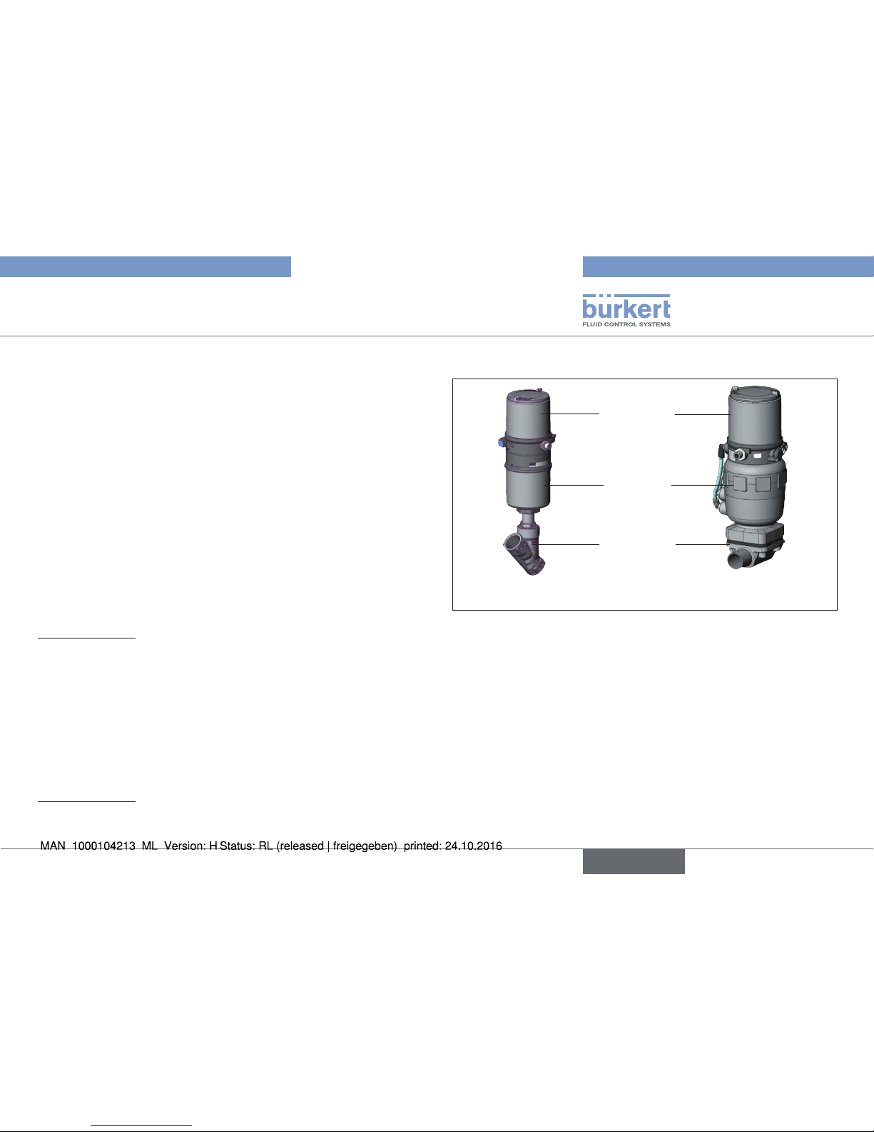
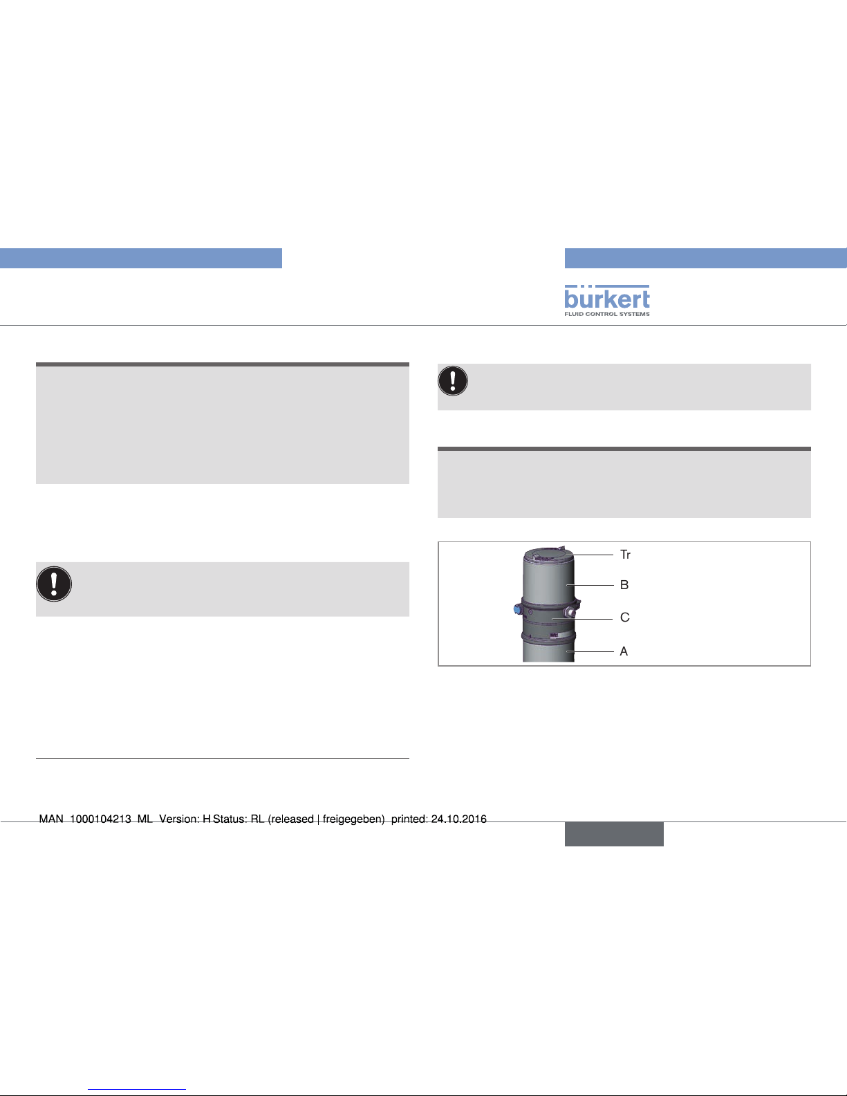
5 STRUCTURE AND FUNCTION
Positioner
Actuator
Valve body
Actuator + Valve body = Process valve
Fig. 1: Structure 1
Positioner Type 8694 is an electropneumatic position controller for
pneumatically actuated control valves with single-acting actuators.
Together with the pneumatic actuator, the positioner forms a functional
unit.
The control valve systems can be used for a wide range of control
tasks in fluid technology and, depending on the application conditions,
different process valves from the Bürkert range can be combined with
the positioner. Angle seat valves, straight seat valves, diaphragm valves
or ball valves are suitable.
The position of the actuator is regulated according to the position
set-point value. The nominal position value is specified by an external
standard signal.
english
Type 8694
Page 8
8
Technical data
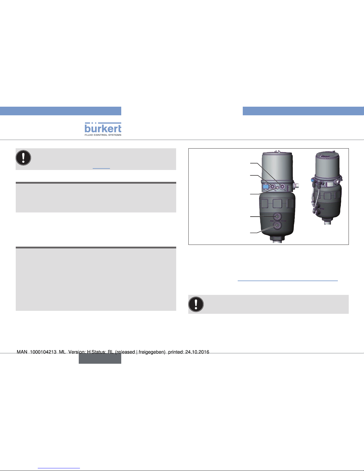
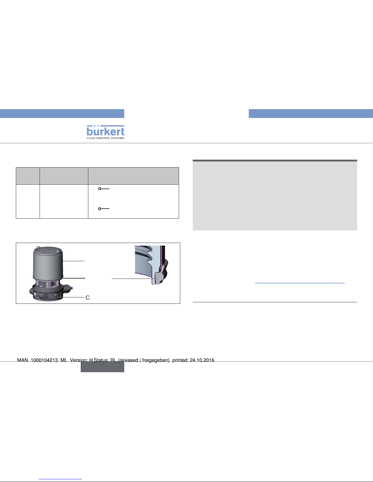
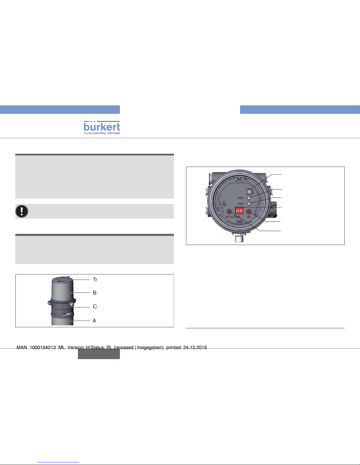
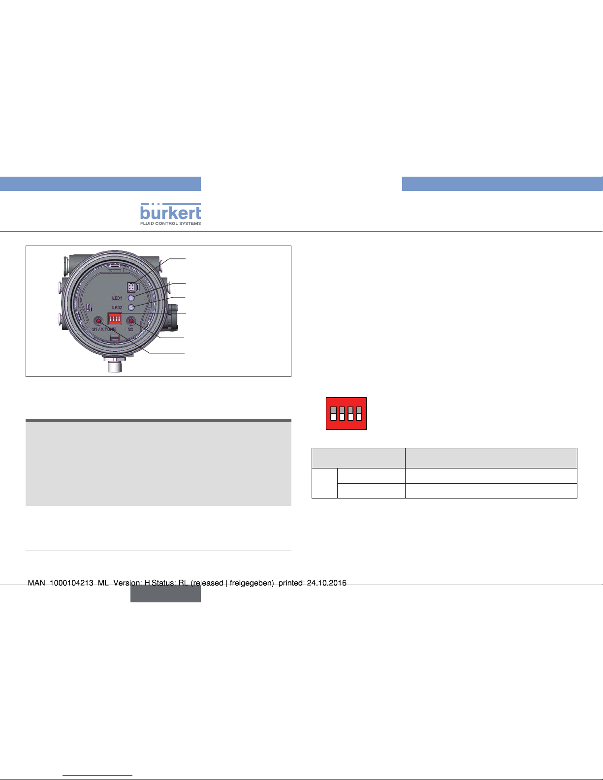
Pilot air port
(label: 1)
Exhaust air port
(label: 3)
Pressure limiting valve
Electrical connection
(cable gland or circular
plug-in connector)
DIP Switches
Keys
Communications interface
LED
Air intake filter
Pilot air outlet only for
series 26xx and 27xx
Additional exhaust air port
(label: 3.1)
only for Type 23xx and 2103
with pilot-operated control
system for high air flow rate
(actuator size ø 130)
Connection housing
Fig. 2: Structure 2
6 TECHNICAL DATA
6.1 Conformity
In accordance with the EC Declaration of conformity, the positioner
Type 8694 is compliant with the EC Directives.
6.2 Standards
The applied standards, which verify conformity with the EC Directives, can be found on the EC-Type Examination Certificate and / or
the EC Declaration of Conformity.
6.3 Licenses
The product is approved for use in zone 2 and 22 in accordance
with ATEX directive 94/9/EC category 3GD.
Observe instructions on operation in an explosion-risk (Ex)
area. Observe the ATEX additional instructions.
The product is cULus approved. Instructions for use in the UL area
see chapter “6.8 Electrical data”.
english
Type 8694
Page 9
9
Technical data
6.4 Operating conditions
WARNING!
Solar radiation and temperature fluctuations may cause malfunctions or leaks.
▶ If the device is used outdoors, do not expose it unprotected to
the weather conditions.
▶ Ensure that the permitted ambient temperature does not exceed
the maximum value or drop below the minimum value.
Ambient temperature see type label
Degree of protection
Evaluated by the manufacturer: Evaluated by UL:
IP65 / IP67 according to EN 60529* UL Type 4x Rating*
* Only if cables, plugs and sockets have been connected correctly and
in compliance with the exhaust air concept see chapter “8 Pneumatic
installation”.
6.5 Mechanical data
Dimensions See data sheet
Housing material exterior: PPS, PC, VA,
interior: PA 6; ABS
Sealing material EPDM / (NBR)
Stroke range
of valve spindle 2–45 mm
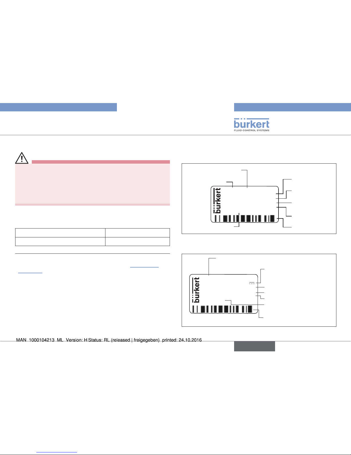
6.6 Type labels
6.6.1 Type label standard (example)
8694 24 V DC
single act
Pilot 0,6
Pmax 7bar
Tamb 0°C - +60°C
S/N 001000
00185134
D-74653 Ingelfingen
W14UN
CE
Identification number
Operating voltage /
Control
Max. operating
pressure
Type
Control function Pilot valve
Bar-code
Serial number CE mark
Max. ambient
temperature
Fig. 3: Type label (example)
6.6.2 UL type label (example)
8694 -E3-...-0 PU02
Single act Pilot 3.0 24V
Pmax 7 bar
Tamb -10 - +55 °C
S/N 1001
00123456
D-74653 Ingelfingen
W15MA
CE
Identification number; Date of
manufacture (encoded)
Max. operating pressure
Type; Features of the type code applicable to UL and
ATEX
Control function; pilot valve;
Supply voltage pilot valve
Bar code
Serial number; CE mark
Max. ambient temperature
Fig. 4: UL type label (example)
english
Type 8694
Page 10
10
Technical data
6.6.3 UL additional label (example)
Degree of protection
Circuit with limited power
Supply voltage device
Type 4X enclosure
NEC Class 2 only
Supply voltage: 24V
Fig. 5: UL additional label (example)
6.7 Pneumatic data
Control medium neutral gases, air
Quality classes in accordance with ISO 8573-1
Dust content Class 7: max. particle size 40 µm,
max. particle density 10 mg/m³
Water content Class 3: max. pressure dew point
- 20 °C or min. 10 °C below the
lowest operating temperature
Oil content Class X: max. 25 mg/m³
Temperature range
control medium -10 – +50 °C
Pressure range
control medium 3 – 7 bar
Air output of pilot valve 7 lN/min (for aeration and deaeration)
(Q
Nn
- value according to definition for
pressure drop from 7 to 6 bar absolute)
optional: 130 lN/min
(for aeration and deaeration)
(only single-acting)
Connections Plug-in hose connector ∅ 6 mm / 1/4“
Socket connection G1/8
6.8 Electrical data
WARNING!
Only circuits with limited power may be used for UL approved
components according to “NEC Class 2”.
6.8.1 Electrical data without bus control
24 V DC
Protection class 3 as per DIN EN 61140 (VDE 0140-1)
Connections Cable gland M16 x 1.5, wrench size 22
(clamping area 5 – 10 mm)
with screw-type terminals for cable crosssections 0.14 – 1.5 mm²
Circular plug-in connector
(M12 x 1, 8-pole)
Pilot valve
Operating voltage 24 V DC ± 10 %
- max. residual ripple 10 %
Power input ≤ 3,5 W
Input resistance for
set-point value signal 75 Ω at 0/4 – 20 mA /
12 bit resolution
english
Type 8694
Page 11
11
Technical data
Analogue position feedback
max. load for current output
0/4 – 20 mA 560 Ω
Digital input 0 – 5 V = log “0”,
12 – 30 V = log “1”
inverted input in reverse order
Communications
interface Direct connection to PC via USB
adapter with integrated interface
driver, communication with communications software.
6.8.2 Electrical data with AS interface bus
control
Protection class 3 as per DIN EN 61140 (VDE 0140-1)
Connections Circular plug-in connector
(M12 x 1, 4-pole)
Operating voltage 29.5 V – 31.6 V DC
(according to specification)
Devices without external supply voltage:
Max. power consumption 150 mA
Devices with external supply voltage:
External supply voltage 24 V ± 10 %
The power supply unit must include a secure disconnection in
accordance with IEC 364-4-41(PELV or SELV)
Max. power consumption 100 mA
Max. power consumption
from AS interface 50 mA
6.9 Factory settings of the positioner
Functions can be activated via DIP switches:
Function Parameter Value
CUTOFF
Sealing function below
Sealing function above
2 %
98 %
CHARACT
Select characteristic FREE
1)
DIR.CMD
Effective direction set-point
value
rise
Tab. 1: Factory settings - Functions
Additional functions are described in the operating instructions Type 8694.
These instructions can be found on the Internet at
www.burkert.com.
1)
Without change to the settings via the communications software a linear
characteristic is stored in FREE.
english
Type 8694
Page 12
12
Installation
7 INSTALLATION
Only for positioner without pre-assembled process valve.
7.1 Safety instructions
DANGER!
Risk of injury from high pressure in the equipment/device.
▶ Before working on equipment or device, switch off the pressure
and deaerate/drain lines.
Risk of electric shock.
▶ Before working on equipment or device, switch off the power
supply and secure to prevent reactivation.
▶ Observe applicable accident prevention and safety regulations
for electrical equipment.
WARNING!
Risk of injury from improper installation.
▶ Installation may be carried out by authorized technicians only
and with the appropriate tools.
Risk of injury from unintentional activation of the system and
an uncontrolled restart.
▶ Secure system from unintentional activation.
▶ Following assembly, ensure a controlled restart.
7.2 Installing the positioner on process
valves belonging to series 2103 and
23xx
NOTE!
When mounting on process valves with a welded body, follow
the installation instructions in the operating instructions for
the process valve.
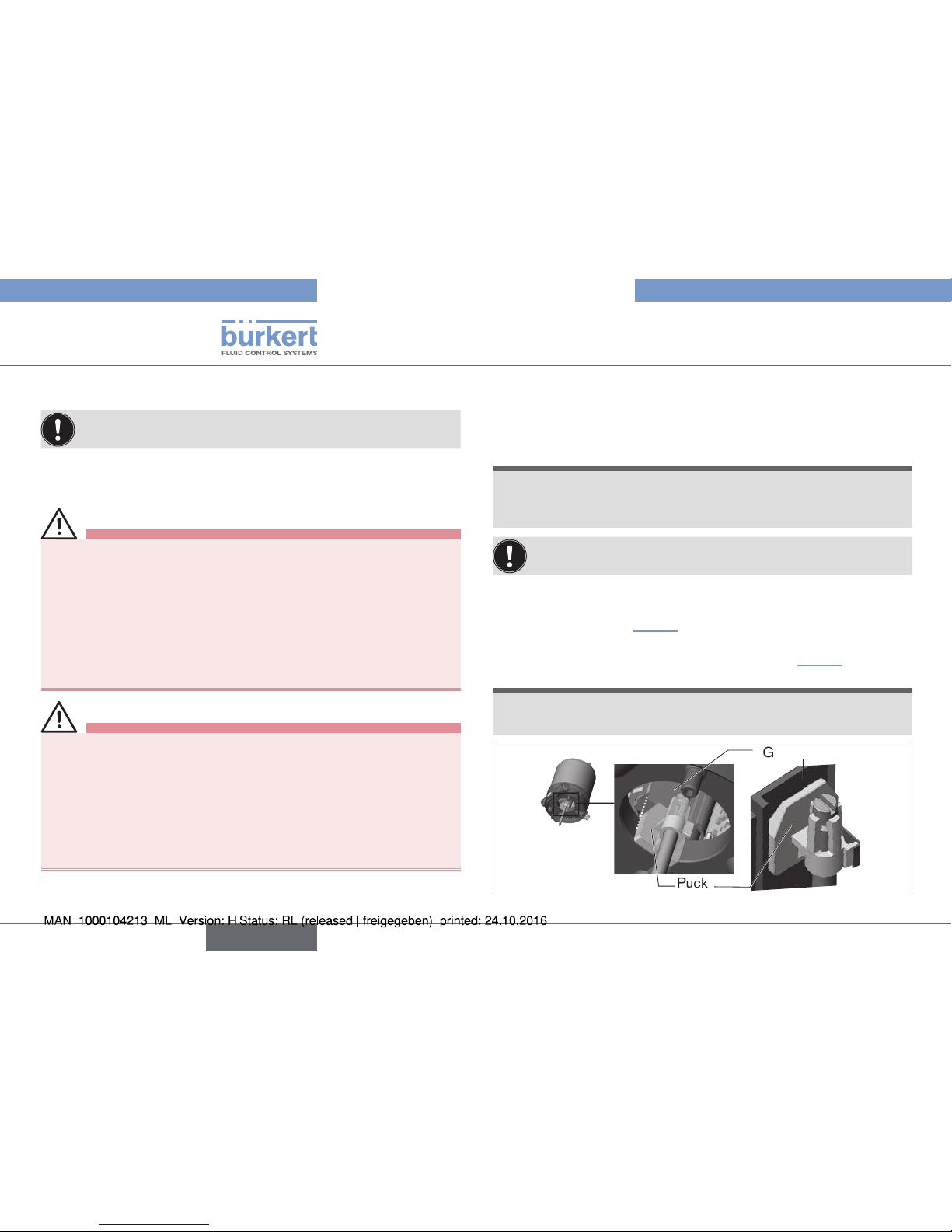
When the positioner is being installed, the collets of the pilot
air ports must not be fitted to the actuator.
→ Align the puck and the positioner until
1. the puck can be inserted into the guide rail of the
positioner (see “Fig. 6”) and
2. the connection pieces of the positioner can be inserted into
the pilot air ports of the actuator (see also “Fig. 6”).
NOTE!
Damaged printed circuit board or malfunction.
▶ Ensure that the puck is situated flat on the guide rail.
Guide rail
Puck
Fig. 6: Aligning the puck
english
Type 8694
Page 13
13
Installation
→ Push the positioner, without turning it, onto the actuator until no
gap is visible on the form seal.
NOTE!
Too high torque when screwing in the fastening screw does
not ensure degree of protection IP65 / IP67.
▶ The fastening screws may be tightened to a maximum torque of
1.5 Nm only.
→ Attach the positioner to the actuator using the two side fastening
screws. In doing so, tighten the screws only hand-tight (max.
torque: 1.5 Nm).
Pilot air
ports
Connection
pieces
Fastening
screws
max. 1.5 Nm
Actuator
Fig. 7: Installing the positioner, series 2103, 2300 and 2301
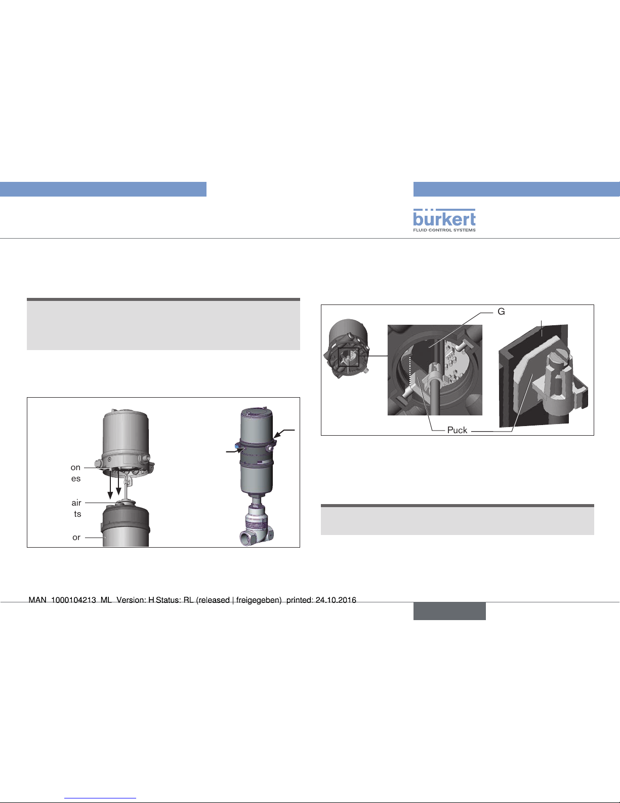
7.3 Installing the positioner on process
valves belonging to series 26xx and
27xx
Procedure:
Guide rail
Puck
Fig. 8: Aligning the puck
→ Push the positioner onto the actuator. The puck must be aligned
in such a way that it is inserted into the guide rail of the positioner.
NOTE!
Damaged printed circuit board or malfunction.
▶ Ensure that the puck is situated flat on the guide rail.
→ Press the positioner all the way down as far as the actuator and
turn it into the required position.
english
Type 8694
Page 14
14
Installation
Ensure that the pneumatic connections of the positioner
and those of the actuator are situated preferably vertically
one above the other (see “Fig. 9”).
NOTE!
Too high torque when screwing in the fastening screw does
not ensure degree of protection IP65 / IP67.
▶ The fastening screws may be tightened to a maximum torque of
1.5 Nm only.
→ Attach the positioner to the actuator using the two side fastening
screws. In doing so, tighten the screws only hand-tight (max.
torque: 1.5 Nm).
NOTE!
Damage or malfunction due to ingress of dirt and moisture.
To observe degree of protection IP65 / IP67:
▶ In the case of actuator size ∅ 80, ∅ 100
connect the pilot air outlet which is not required to the free pilot
air port of the actuator or seal with a plug.
▶ In the case of actuator size ∅ 125
seal the pilot air outlet 2
2
which is not required with a plug and
feed the free pilot air port of the actuator via a hose into a dry
environment.
Pilot air outlet 2
1
Pilot air outlet 2
2
Upper pilot air port
Lower pilot air port
Fastening screws
max. 1.5 Nm
Example ∅ 80,
CFA
Fig. 9: Installing the pneumatic connection to actuator, series 26xx and
27xx
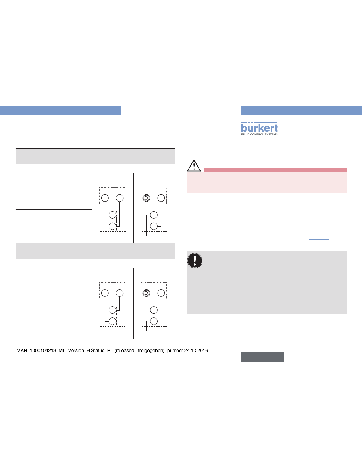
→ Make the pneumatic connection between the positioner and
actuator with the “Tab. 2: Pneumatic connection to actuator”.
“In rest position” means that the pilot valves of the positioner
Type 8694 are isolated or not actuated.
english
Type 8694
Page 15
15
Pneumatic installation
Control function A (CFA)
Process valve closed in rest position (by spring force)
Actuator size ∅ 80, ∅ 100
∅ 125
Positioner
Pilot air outlet
222
1
222
1
Actuator
Upper pilot air port
Lower pilot air port
Dry area
Control function B (CFB)
Process valve open in rest position (by spring force)
Actuator size ∅ 80, ∅ 100
∅ 125
Positioner
Pilot air outlet
222
1
222
1
Actuator
Upper pilot air port
Lower pilot air port
Dry area
Tab. 2: Pneumatic connection to actuator
8 PNEUMATIC INSTALLATION
DANGER!
Risk of injury from high pressure in the equipment/device.
▶ Before working on equipment or device, switch off the pressure
and deaerate/drain lines.
Procedure:
→ Connect the control medium to the pilot air port (1)
(3 – 7 bar; instrument air, free of oil, water and dust).
→ Attach the exhaust air line or a silencer to the exhaust air port (3)
and, if available to the exhaust air port (3.1) (see “Fig. 10”).
Keep the adjacent supply pressure always at least 0.5 – 1
bar above the pressure which is required to move the actuator
to its end position. This ensures that the control behavior is
not extremely negatively affected in the upper stroke range on
account of too little pressure difference.
During operation keep the fluctuations of the pressure supply
as low as possible (max. ±10 %). If fluctuations are greater,
the control parameters measured with the X.TUNE function
are not optimum.
english
Type 8694
Page 16
16
Electrical installation
Important information for the problem-free functioning of
the device:
▶ The installation must not cause back pressure to build up.
▶ Select a hose for the connection with an adequate
cross-section.
▶ The exhaust air line must be designed in such a way that
no water or other liquid can get into the device through the
exhaust air port (3) or (3.1).
Additional exhaust air port
(label: 3.1)
only for Type 23xx and 2103
with pilot-operated control system
for high air flow rate (actuator size ø 130)
Pilot air port
(label: 1)
Exhaust air port
(label: 3)
Fig. 10: Pneumatic connection
Caution: (Exhaust air concept): In compliance with degree
of protection IP67, an exhaust air line must be installed in the
dry area.
9 ELECTRICAL INSTALLATION
All electrical inputs and outputs of the device are not galvanically
isolated from the supply voltage.
9.1 Safety instructions
DANGER!
Risk of electric shock.
▶ Before working on equipment or device, switch off the power
supply and secure to prevent reactivation.
▶ Observe applicable accident prevention and safety regulations
for electrical equipment.
WARNING!
Risk of injury from improper installation.
▶ Installation may be carried out by authorized technicians only
and with the appropriate tools.
Risk of injury from unintentional activation of the system and
an uncontrolled restart.
▶ Secure system from unintentional activation.
▶ Following installation, ensure a controlled restart.
9.2 Electrical installation 24 V DC
Two kinds of connections are used for the electrical bonding of the
positioner:
• Cable gland with screw-type terminals
• Multi-pole with circular plug-in connector M12 x 1, 8-pole
english
Type 8694
Page 17
17
Electrical installation
9.2.1 Electrical installation with cable gland
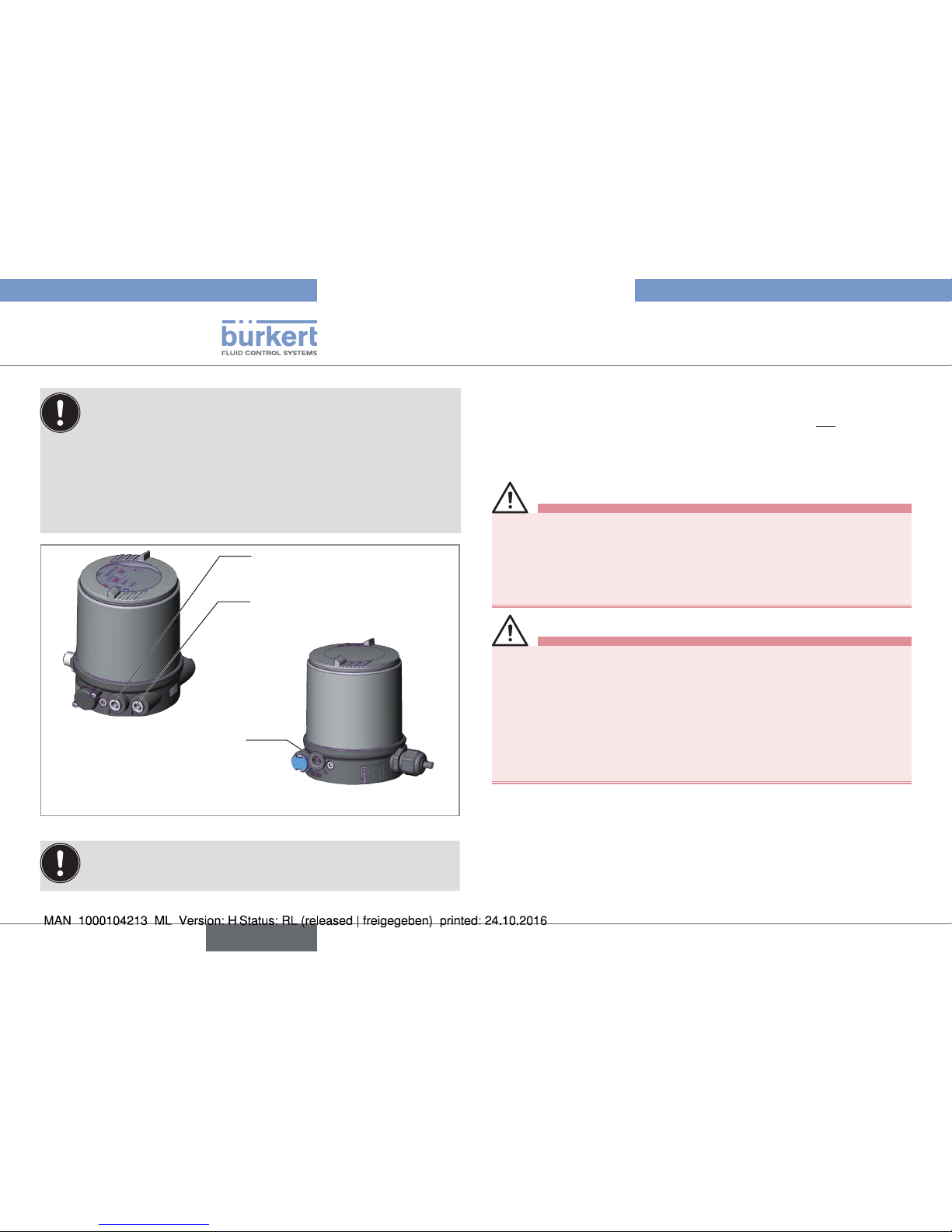
NOTE!
Breakage of the pneumatic connection pieces due to rotational impact.
▶ When unscrewing and screwing in the body casing, do not hold
the actuator of the process valve but the connection housing.
→ Unscrew the body casing (stainless steel) in a counter-clockwise
direction.
Body casing
Connection housing
Actuator
Fig. 11: Open positioner
→ Push the cables through the cable gland.
→ Connect the wires.
1
2
2)
3
2)
4
5
6
7
Fig. 12: Screw-type terminals
Input signals from the control centre (e.g. PLC)
Terminal Configuration External circuit / signal level
4
5
Set-point value +
Set-point value
GND
4
5
+ (0/4 ... 24 mA)
GND
1 Digital input + 1
+
0 ... 5 V (log. 0)
10 ... 30 V (log. 1)
with reference to terminal 7 (GND)
Tab. 3: Assignment of screw-type terminals - input signals of the control
center
Operating voltage
Terminal Configuration External circuit
6
7
Operating voltage +
Operating voltage
GND
6
7
24 V DC ± 10 %
max. residual ripple
10 %
Tab. 4: Assignment of screw-type terminals - operating voltage
english
Type 8694
Page 18
18
Electrical installation
Output signals to the control center (e.g. PLC; for analog
output option only)
Terminal Configuration External circuit / signal level
2
3
Analogue position
feedback +
Analogue position
feedback GND
+ (0/4 ... 24 mA)
2
3
GND
Tab. 5: Assignment of screw-type terminals - output signals to the control
center - option
Seal
Body casing
Body casing
Connection housing
Fig. 13: Position of the seal in the body casing
→ Check that the seal is correctly positioned in the body casing.
NOTE!
Breakage of the pneumatic connection pieces due to rotational impact.
▶ When unscrewing and screwing in the body casing, do not hold
the actuator of the process valve but the connection housing.
Damage or malfunction due to penetration of dirt and humidity.
To ensure degree of protection IP65 / IP67:
▶ Tighten the union nut on the cable gland according to the cable
size or dummy plugs used (approx. 1.5 Nm).
▶ Screw the body casing in all the way.
→ Tighten union nut on the cable gland (torque approx. 1.5 Nm).
→ Close the device (assembly tool: 674077
2)
).
When the supply voltage is applied, the positioner is operating.
→ Actuate the automatic adjustment of the positioner, as described
in the chapter entitled
“10.2 Automatic adjustment X.TUNE”.
2) The assembly tool (674077) is available from your Bürkert sales office.
english
Type 8694
Page 19
19
Electrical installation
9.2.2 Electrical installation 24 V DC with
circular plug-in connector
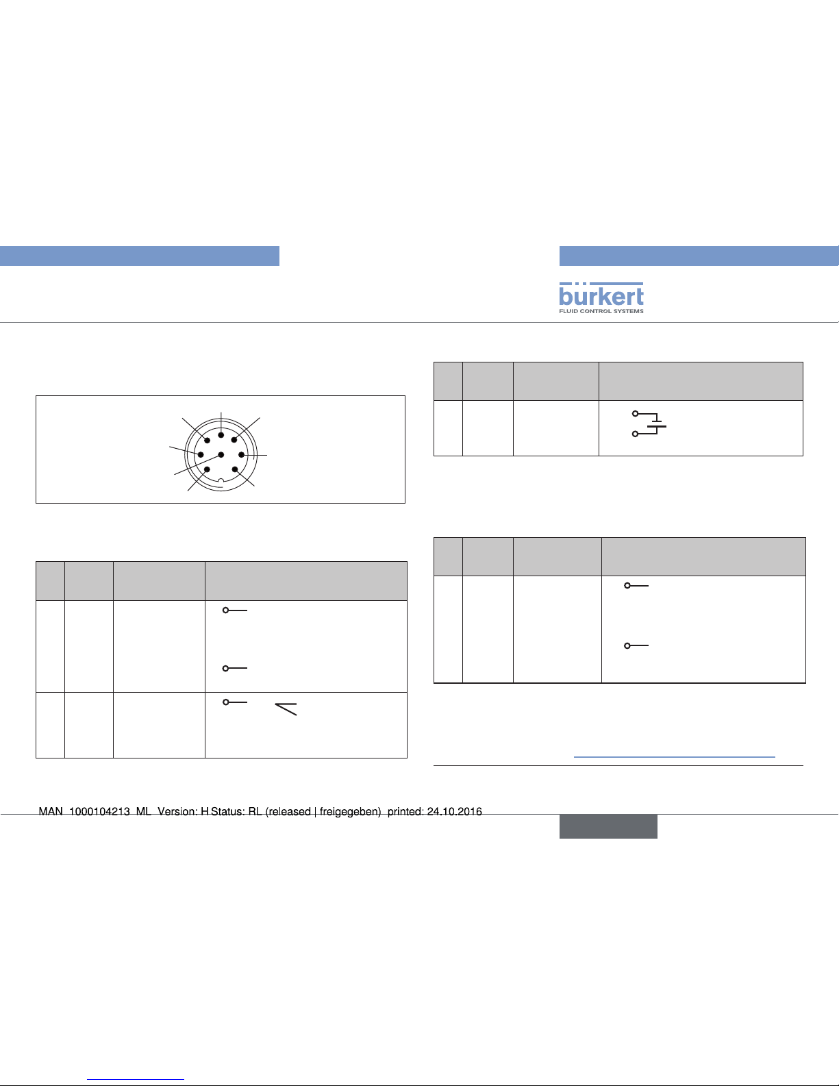
→ Connect the positioner according to the table.
6
1
7
5
4
3
2
8
Fig. 14: Circular plug M12 x 1, 8-pole
Input signals of the control center (e.g. PLC)
Pin
Wire
color
3)
Configuration External circuit / signal level
1
2
white
brown
Set-point value
+
(0/4 ... 20 mA)
Set-point value
GND
1
2
+ (0/4 ... 24 mA)
GND
5 6 grey
pink
Digital input +
Digital input
GND
5
+
0 ... 5 V (log. 0)
10 ... 30 V (log. 1)
identical to Pin 3 (GND)
Tab. 6: Pin assignment - input signals of the control center
Operating voltage
Pin
Wire
color
3)
Configuration External circuit
3 4green
yellow
GND
+ 24 V
3
4
24 V DC ± 10 %
max. residual ripple
10 %
Tab. 7: Pin assignment - operating voltage
Output signals to the control center (e.g. PLC) - (required for
analogue output option only)
Pin
Wire
color
3)
Configuration External circuit / signal level
8
7
red
blue
Analogue
position
feedback +
Analogue
position
feedback GND
+ (0/4 ... 24 mA)
8
7
GND
Tab. 8: Pin assignment - output signals of the control center - option
When the supply voltage is applied, the positioner is operating.
→ Actuate the automatic adjustment of the positioner, as described
in the chapter entitled “10.2 Automatic adjustment X.TUNE”.
3) The indicated colors refer to the connecting cable available as an
accessory (919061).
english
Type 8694
Page 20
20
Electrical installation
9.3 Electrical installation AS Interface
A detailed description of the bus communication can be
found in the operating instructions Type 8694.
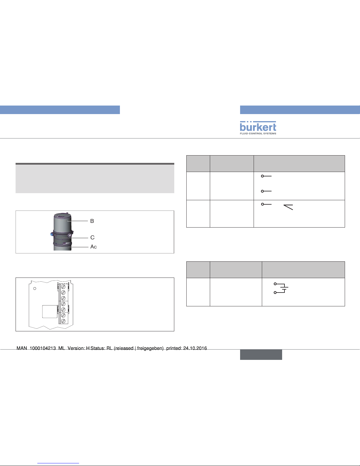
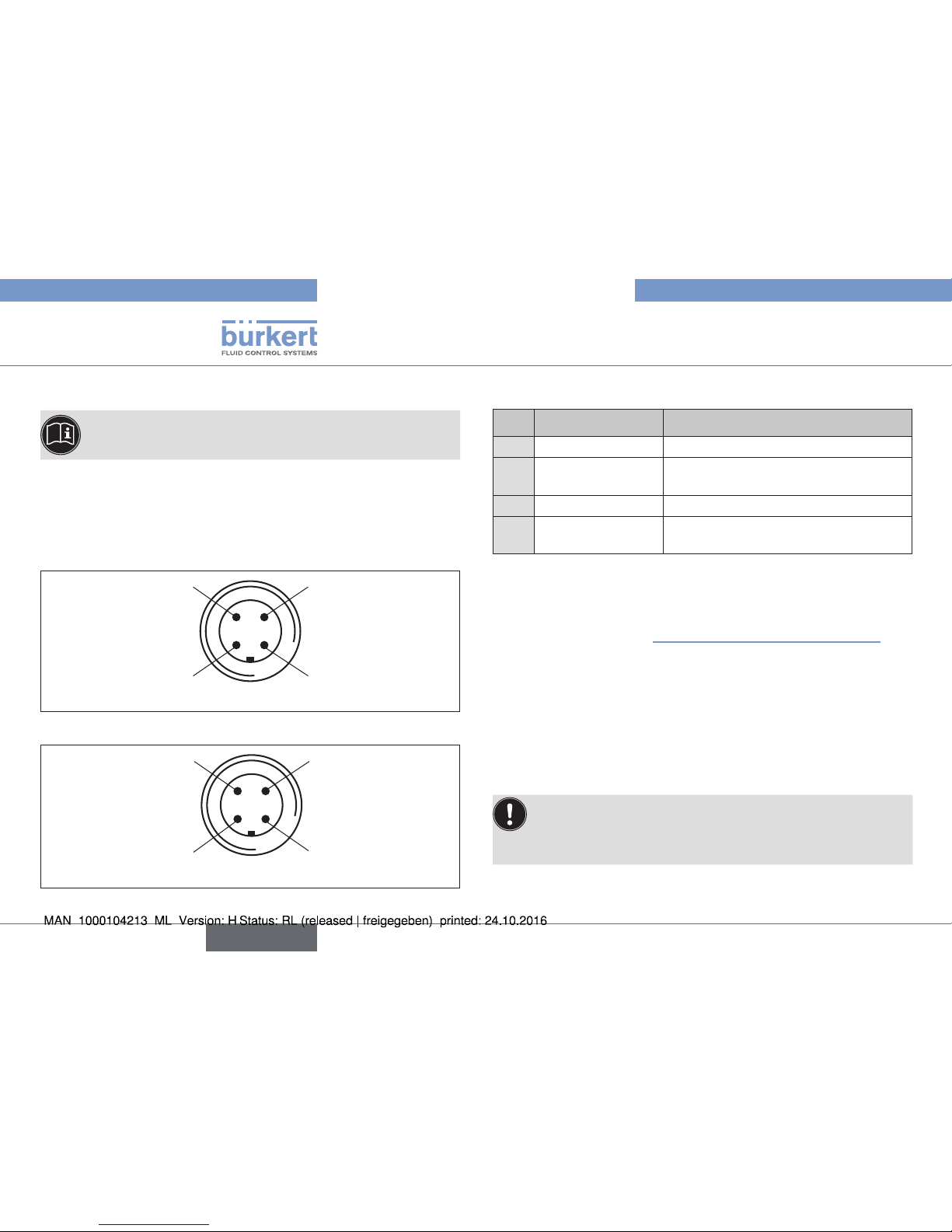
9.3.1 Connection with circular plug-in
connector M12 x 1, 4-pole, male
Connector views
The views show the image from the front looking at the pins, the
solder connections are behind them.
Pin 4:
NC
Pin 1:
Bus +
Pin 3:
Bus –
Pin 2:
NC
Fig. 15: Bus connection without external supply voltage
Pin 4:
24 V +
Pin 1:
Bus +
Pin 3:
Bus –
Pin 2:
GND
Fig. 16: Bus connection with external supply voltage (optional)
Bus connection without external / with external supply voltage
Pin Designation Configuration
1
Bus + AS Interface bus line +
2
NC or GND
(optional)
not used or external supply voltage –
(optional)
3
Bus – AS Interface bus line –
4
NC or 24 V +
(optional)
not used or external supply voltage +
(optional)
Tab. 9: Pin assignment of circular plug-in connector for AS Interface
When the supply voltage is applied, the positioner is operating.
→ Actuate the automatic adjustment of the positioner, as described
in the chapter entitled “10.2 Automatic adjustment X.TUNE”.
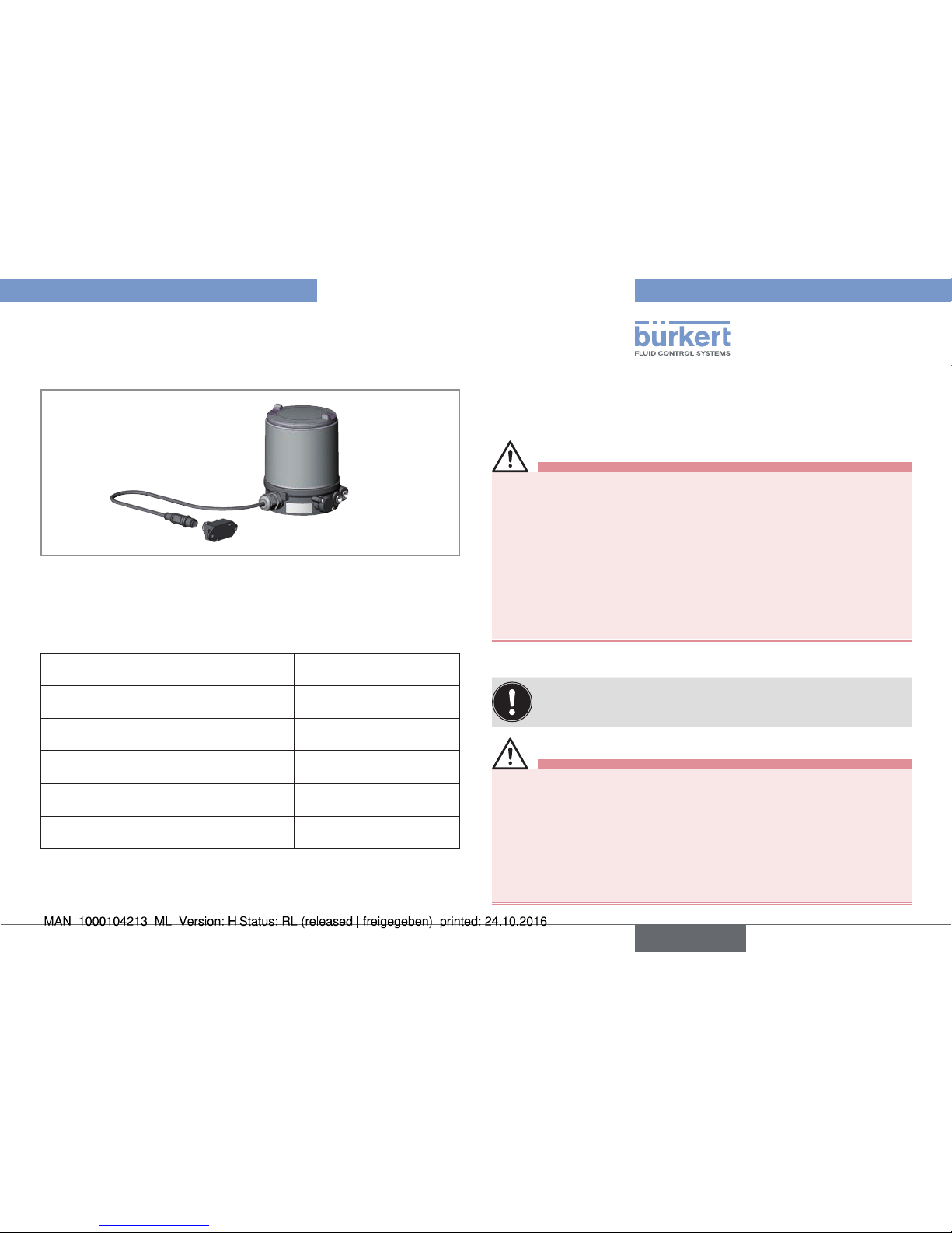
9.3.2 Connection with multi-pole cable and
ribbon cable terminal
As an alternative to the bus connection model with 4-pole circular
plug, there is the positioner with multi-pole cable (M12 circular plug)
and ribbon cable terminal. The wiring diagram of the circular plug corresponds to the bus connection of the M12 4-pole circular plug and
can easily be connected to the ribbon cable terminal.
The bus line may have a maximum length of 100 m. When
designing the system, consider the length of the cable which
is fed directly to the positioner for the maximum bus line length
(see example calculation in the operating instructions).
english
Type 8694
Page 21
21
Start-up
Fig. 17: Positioner 8694 with multi-pole cable and ribbon cable terminal
9.3.3 Programming data AS Interface
Version Profile S-7.3.4 Version Profile S-7.A.5
I/O configuration
7 hex 7 hex
ID code 3 hex (analog profile) A hex
Extended
ID code 1
F hex (Default value, can
be changed by the user)
7 hex
Extended
ID code 2
4 hex 5 hex
Profile S-7.3.4 S-7.A.5
Tab. 10: Programming data
10 START-UP
10.1 Safety instructions
WARNING!
Risk of injury from improper operation.
Improper operation may result in injuries as well as damage to the
device and the area around it.
▶ Before start-up, ensure that the operating personnel are familiar
with and completely understand the contents of the operating
instructions.
▶ Observe the safety instructions and intended use.
▶ Only adequately trained personnel may operate the equipment/
the device.
10.2 Automatic adjustment X.TUNE
To adjust the positioner to local conditions, the X.TUNE
function must be run following installation.
WARNING!
Danger due to the valve position changing when the X.TUNE
function is running.
When the X.TUNE is running under operating pressure, there is an
acute risk of injury.
▶ Never run X.TUNE while a process is running.
▶ Take appropriate measures to prevent the equipment from being
accidentally actuated.
english
Type 8694
Page 22
22
Start-up
NOTE!
Avoid maladjustment of the controller due to an incorrect
pilot pressure or applied operating medium pressure.
▶ Run X.TUNE whenever the pilot pressure (= pneumatic auxil-
iary energy) is available during subsequent operation.
• Run the X.TUNE function preferably without operating medium
pressure to exclude interference caused by flow forces.
To run X.TUNE, the positioner must be in the AUTOMATIC
operating status (DIP switch 4 = OFF).
NOTE!
Breakage of the pneumatic connection pieces due to rotational impact.
▶ When unscrewing and screwing in the transparent cap, do not
hold the actuator of the process valve but the connection housing.
Body casing
Transparent cap
Connection housing
Actuator
Fig. 18: Open positioner
→ Screw off the transparent cap of the positioner to operate the
keys and DIP switches.
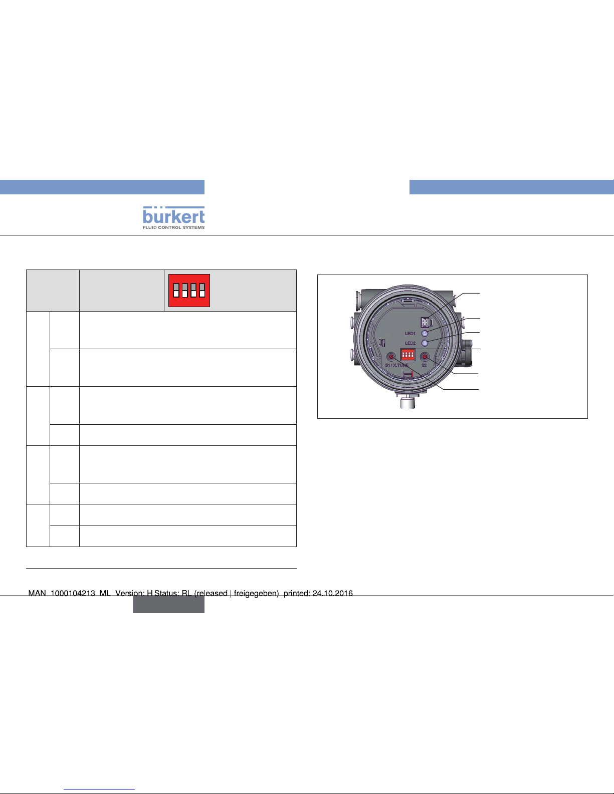
1 2 3 4
ON DIP
Communications
interface
LED 1
LED 2
DIP Switches
Key 1
Key 2
Fig. 19: Automatic adjustment X.TUNE
→ Start the X.TUNE by pressing key 1
4)
for 5 s.
While the X.TUNE is running, LED 1 flashes quickly (green).
When the automatic adjustment is complete, LED 1 flashes slowly
(green)
5)
.
The changes are automatically transferred to the memory (EEPROM)
provided the X.TUNE function is successful.
4) The X.TUNE can also be started via communications software.
5) If a fault occurs, LED 1 is lit red.
english
Type 8694
Page 23
23
Start-up
NOTE!
Breakage of the pneumatic connection pieces due to rotational impact.
▶ When unscrewing and screwing in the transparent cap, do not
hold the actuator of the process valve but the connection housing.
Damage or malfunction due to penetration of dirt and humidity.
▶ To observe degree of protection IP65 / IP67, screw the trans-
parent cap in all the way.
→ Close the device (assembly tool: 674077
6)
).
Important:
When the Teach function is activated the actuator cannot
be actuated via the AS Interface.
6) The assembly tool (674077) is available from your Bürkert sales office.
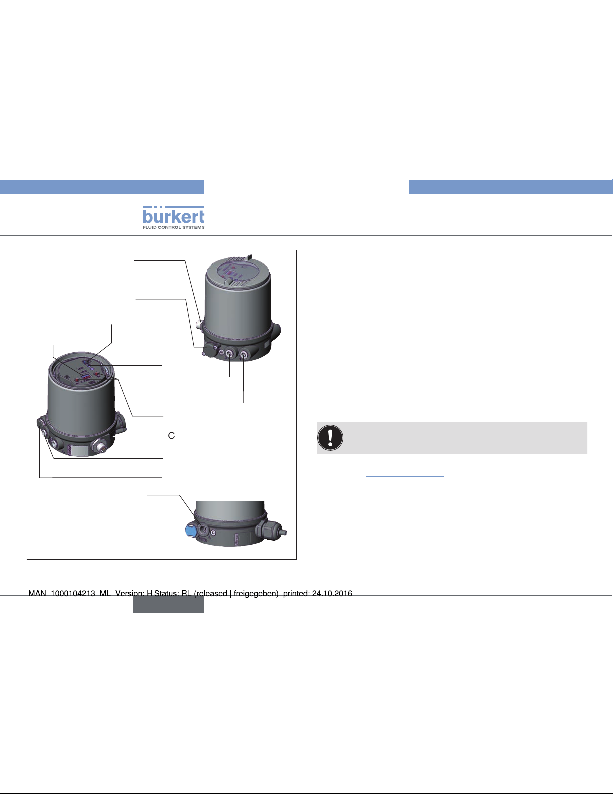
10.3 Control and display elements
A detailed description of the operation and functions of the
positioner and the communication software can be found in
the respective operating instructions.
NOTE!
Breakage of the pneumatic connection pieces due to rotational impact.
▶ When unscrewing and screwing in the transparent cap, do not
hold the actuator of the process valve but the connection housing.
Body casing
Transparent cap
Connection housing
Actuator
Fig. 20: Open positioner
→ Screw off the transparent cap of the positioner to operate the
keys and DIP switches.
english
Type 8694
Page 24
24
Start-up
1 2 3 4
ON DIP
Communications
interface
LED 1
LED 2
DIP Switches
Key 1
Key 2
Fig. 21: Description of the control elements
NOTE!
Breakage of the pneumatic connection pieces due to rotational impact.
▶ When unscrewing and screwing in the transparent cap, do not
hold the actuator of the process valve but the connection housing.
Damage or malfunction due to penetration of dirt and humidity.
▶ To observe degree of protection IP65 / IP67, screw the trans-
parent cap in all the way.
→ Close the device (assembly tool: 674077
7)
).
7) The assembly tool (674077) is available from your Bürkert sales office.
10.3.1 Operating status
AUTOMATIC (AUTO)
Normal controller mode is implemented and monitored in AUTO-
MATIC operating state.
LED 1 flashes green.
MANUAL (MANU)
In MANUAL operating state the valve can be opened and closed
manually via the keys.
LED 1 flashes red / green alternately.
ON DIP
1
2 3 4
The DIP switch 4 can be used to switch between
the two operating states AUTOMATIC and
MANUAL.
DIP switches Function
4 ON Operating status MANUAL (MANU)
OFF Operating status AUTOMATIC (AUTO)
Tab. 11: DIP switches
english
Type 8694
Page 25
25
Start-up
10.3.2 Functions of the keys
The configuration of the 2 keys on the board varies depending on the
operating status (AUTOMATIC / MANUAL).
1 2 3 4
ON DIP
Communications
interface
LED 1
LED 2
DIP switches
Key 1
Key 2
Fig. 22: Keys
MANUAL operating status (DIP switch 4 set to ON):
Key Function
8)
1 Aerate (manually open / close the actuator)
9)
2 Deaerate (manually open / close the actuator)
9)
Tab. 12: Configuration of the keys for MANUAL operating status
AUTOMATIC operating status (DIP switch 4 set to OFF):
Key Function
1 Press for 5 s to start the X.TUNE function
2 -
Tab. 13: Configuration of the keys for AUTOMATIC operating status
8) No function if the digital input was activated with the “Manual/Auto
change-over” via the communications software.
9) Depending on the operating principle of the actuator.
english
Type 8694
Page 26
26
Start-up
10.3.3 Function of the DIP switches
DIP
switches
Function
ON DIP
1
2 3 4
1 ON Reversal of the effective direction of the set-point
value (set-point value 20 – 4 mA corresponds to
position 0 – 100 %), descending (DIR.CMD)
OFF Normal effective direction of the set-point value
(set-point value 4 – 20 mA corresponds to position
0 – 100 %), ascending
2 ON Sealing function active. The valve completely closes
below 2 %
10)
and opens above 98 % of the set-point
value (CUTOFF)
OFF No sealing function
3 ON Correction characteristic for adjustment of the oper-
ating characteristic (linearization of the process characteristic CHARACT)
10)
OFF Linear characteristic
4 ON Operating status MANUAL (MANU)
OFF Operating status AUTOMATIC (AUTO)
Tab. 14: DIP switches
10) Can be changed via communications software.
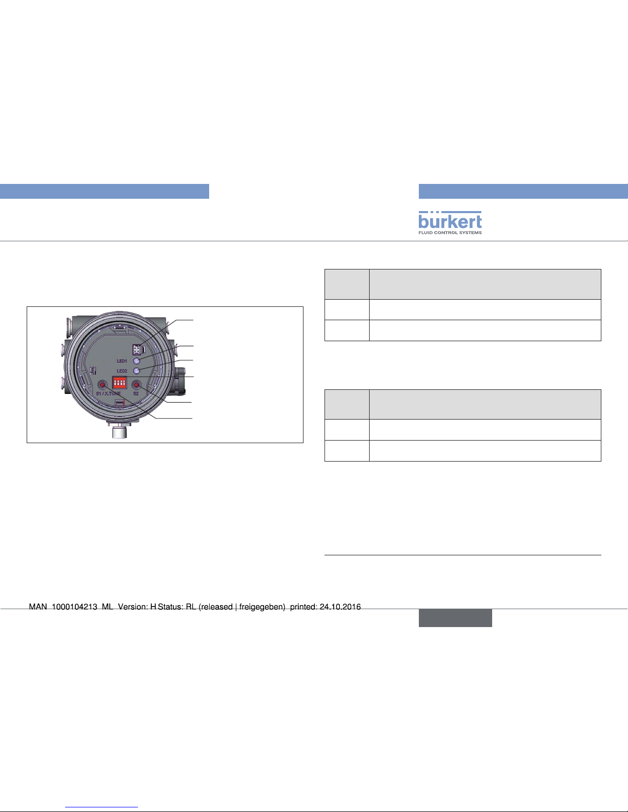
10.3.4 Display of the LEDs
1 2 3 4
ON DIP
Communications
interface
LED 1
LED 2
DIP switches
Key 1
Key 2
Fig. 23: Display of the LEDs
LED 1
(green / red)
Display of
AUTO, MANU, X.TUNE and FAULT
LED 2
(green / yellow)
Display of state of actuator
(open, closed, opens or closes)
english
Type 8694
Page 27

27
Safety Positions
LED 1 (green / red)
LED States
Display
green red
on off Acceleration phase when Power ON
flashes slowly off Operating status AUTO (AUTOMATIC)
flashing flashing
MANUAL operating status
alternating
flashes quickly off X.TUNE function
off on ERROR (see operating instructions)
off
flashes
slowly
AUTO operating status for sensor break
detection
Tab. 15: Display LED 1
LED 2 (green / yellow)
LED States
Display
green yellow
on off Actuator closed
off on Actuator open
flashes
slowly
off
Remaining control deviation
(actual value > set-point value)
off
flashes
slowly
Remaining control deviation
(actual value < set-point value)
flashes
quickly
off Closing in MANUAL operating status
off
flashes
quickly
Opening in MANUAL operating status
Tab. 16: Display LED 2
11 SAFETY POSITIONS
Actuator
system
Designation
Safety positions after
failure of the auxiliary
power
electrical pneumatic
up
down
single-acting
Control
function A
down
pilot-controlled
control system:
down
direct-acting
control system:
not defined
up
down
single-acting
Control
function B
up
pilot-controlled
control system:
up
direct-acting
control system:
not defined
Tab. 17: Safety positions
english
Type 8694
Page 28

28
Accessories
12 ACCESSORIES
Designation Order no.
USB adapter for connection to a PC in conjunction with an extension cable
227093
Communicator
Information at
www.burkert.com
Connection cable M12 x 1, 8-pole 919061
Assembly tool 647077
Tab. 18: Accessories
12.1 Communications software
The PC operating program “Communicator” is designed for communication with the devices from the Bürkert positioner family (valid since
serial number 20000).
A detailed description and precise schedule of the procedure
for the installation and operation of the software can be found
in the associated documentation.
12.2 USB interface
The PC requires an USB interface for communication with the positioners as well as an additional adapter with interface driver (see
“Tab. 18”).
12.3 Download
Download the software at: www.burkert.com
13 PACKAGING, TRANSPORT,
STORAGE
NOTE!
Transport damages.
Inadequately protected equipment may be damaged during transport.
▶ During transportation protect the device against wet and dirt in
shock-resistant packaging.
▶ Avoid exceeding or dropping below the permitted storage
temperature.
Incorrect storage may damage the device.
▶ Store the device in a dry and dust-free location.
▶ Storage temperature -20 – +65 °C.
Damage to the environment caused by device components
contaminated with media.
▶ Dispose of the device and packaging in an environmentally friendly
manner.
▶ Observe applicable regulations on disposal and the environment.
english
Type 8694
Page 29

29
1 DER QUICKSTART ....................................................................................30
1.1 Begriffsdefinition / Abkürzung ..............................................30
1.2 Darstellungsmittel ....................................................................30
2 BESTIMMUNGSGEMÄSSE VERWENDUNG................................31
2.1 Beschränkungen ......................................................................31
3 GRUNDLEGENDE SICHERHEITSHINWEISE .............................. 31
4 ALLGEMEINE HINWEISE ....................................................................... 33
4.1 Kontaktadresse ........................................................................33
4.2 Gewährleistung ........................................................................33
4.3 Informationen im Internet .......................................................33
5 AUFBAU UND FUNKTION .................................................................... 33
6 TECHNISCHE DATEN ............................................................................. 34
6.1 Konformität ................................................................................34
6.2 Normen ......................................................................................34
6.3 Zulassungen .............................................................................34
6.4 Betriebsbedingungen .............................................................35
6.5 Mechanische Daten ................................................................35
6.6 Typschilder ................................................................................35
6.7 Pneumatische Daten ..............................................................36
6.8 Elektrische Daten ....................................................................36
6.9 Werkseinstellungen des Positioners ...................................37
7 MONTAGE
..................................................................................................... 38
7.1 Sicherheitshinweise ................................................................38
7.2 Montage Positioner an Prozessventile der Reihe 2103,
2300 und 2301 .......................................................................38
7.3 Montage Positioner an Prozessventile der Reihe 26xx
und 27xx ........................................................................................ 39
8 PNEUMATISCHE INSTALLATION ....................................................... 41
9 ELEKTRISCHE INSTALLATION ........................................................... 42
9.1 Sicherheitshinweise ................................................................42
9.2 Elektrische Installation 24 V DC ..........................................42
9.3 Installation für AS-Interface ...................................................46
10 INBETRIEBNAHME
................................................................................... 47
10.1 Sicherheitshinweise ................................................................47
10.2 Automatische Anpassung (X.TUNE) ................................ 47
10.3 Bedienung und Anzeigeelemente ........................................49
11 SICHERHEITSSTELLUNGEN
.............................................................. 53
12 ZUBEHÖR
.....................................................................................................54
12.1 Kommunikation-Software ......................................................54
12.2 USB-Schnittstelle ...................................................................54
12.3 Download ..................................................................................54
13 TRANSPORT, LAGERUNG, VERPACKUNG ..................................54
Inhaltsverzeichnis
Typ 8694
deutsch
Page 30

30
Der Quickstart
1 DER QUICKSTART
Der Quickstart beschreibt den gesamten Lebenszyklus des Geräts.
Bewahren Sie diese Anleitung so auf, dass sie für jeden Benutzer gut
zugänglich ist und jedem neuen Eigentümer des Geräts wieder zur
Verfügung steht.
Wichtige Informationen zur Sicherheit.
Lesen Sie den Quickstart sorgfältig durch. Beachten Sie vor allem
die Kapitel „Grundlegende Sicherheitshinweise“ und „Bestimmungsgemäße Verwendung“.
▶ Der Quickstart muss gelesen und verstanden werden.
Der Quickstart erläutert beispielhaft die Montage und Inbetriebnahme
des Geräts.
Die ausführliche Beschreibung des Geräts finden Sie in der Bedienungsanleitung für den Typ 8694.
Die Bedienungsanleitung finden Sie auf der beigelegten CD
oder im Internet unter:
www.buerkert.de
1.1 Begriffsdefinition / Abkürzung
Der in dieser Anleitung verwendete Begriff „Gerät“ steht immer für
den Positioner Typ 8694.
Die in dieser Anleitung verwendete Abkürzung „Ex“ steht immer für
„explosionsgefährdet“.
1.2 Darstellungsmittel
In dieser Anleitung werden folgende Darstellungsmittel verwendet.
GEFAHR!
Warnt vor einer unmittelbaren Gefahr.
▶ Bei Nichtbeachtung sind Tod oder schwere Verletzungen die Folge.
WARNUNG!
Warnt vor einer möglicherweise gefährlichen Situation.
▶ Bei Nichtbeachtung können schwere Verletzungen oder Tod die
Folge sein.
VORSICHT!
Warnt vor einer möglichen Gefährdung.
▶ Nichtbeachtung kann mittelschwere oder leichte Verletzungen
zur Folge haben.
HINWEIS!
Warnt vor Sachschäden.
Wichtige Tipps und Empfehlungen.
verweist auf Informationen in dieser Bedienungsanleitung
oder in anderen Dokumentationen.
▶ markiert eine Anweisung zur Gefahrenvermeidung.
→ markiert einen Arbeitsschritt, den Sie ausführen müssen.
Typ 8694
deutsch
Page 31

31
Bestimmungsgemäße Verwendung
2 BESTIMMUNGSGEMÄSSE
VERWENDUNG
Bei nicht bestimmungsgemäßer Verwendung des Positioners
Typ 8694 können Gefahren für Personen, Anlagen in der
Umgebung und die Umwelt entstehen.
▶ Das Gerät ist für den Anbau an pneumatische Antriebe von Pro-
zessventilen zur Steuerung von Medien konzipiert.
▶ Das Gerät nicht der direkten Sonneneinstrahlung aussetzen.
▶ Für den Einsatz die in den Vertragsdokumenten und der Bedie-
nungsanleitung spezifizierten zulässigen Daten, Betriebs- und
Einsatzbedingungen beachten. Diese sind im Kapitel „6 Techni-
sche Daten“ beschrieben.
▶ Das Gerät nur in Verbindung mit von Bürkert empfohlenen bzw.
zugelassenen Fremdgeräten und -komponenten einsetzen.
▶ Angesichts der Vielzahl von Einsatz- und Verwendungsfällen,
muss vor dem Einbau geprüft und erforderlichenfalls getestet
werden, ob das Gerät für den konkreten Einsatzfall geeignet ist.
▶ Voraussetzungen für den sicheren und einwandfreien Betrieb
sind sachgemäßer Transport, sachgemäße Lagerung und Instal-
lation sowie sorgfältige Bedienung und Instandhaltung.
▶ Das Gerät nur bestimmungsgemäß verwenden.
2.1 Beschränkungen
Beachten Sie bei der Ausfuhr des Systems oder Geräts gegebenenfalls
bestehende Beschränkungen.
3 GRUNDLEGENDE
SICHERHEITSHINWEISE
Diese Sicherheitshinweise berücksichtigen keine
• Zufälligkeiten und Ereignisse, die bei Montage, Betrieb und Wartung
der Geräte auftreten können.
• ortsbezogenen Sicherheitsbestimmungen, für deren Einhaltung, auch
in Bezug auf das Montagepersonal, der Betreiber verantwortlich ist.
Verletzungsgefahr durch hohen Druck in Anlage bzw. Gerät.
▶ Vor Arbeiten an Anlage oder Gerät, den Druck abschalten und
Leitungen entlüften bzw. entleeren.
Gefahr durch Stromschlag.
▶ Vor Arbeiten an Anlage oder Gerät, die Spannung abschalten und
vor Wiedereinschalten sichern.
▶ Die geltenden Unfallverhütungs- und Sicherheitsbestimmungen
für elektrische Geräte beachten.
Typ 8694
deutsch
Page 32

32
Grundlegende Sicherheitshinweise
Allgemeine Gefahrensituationen.
Zum Schutz vor Verletzungen ist zu beachten:
▶ Im explosionsgefährdeten Bereich darf der Positioner Typ 8694
nur entsprechend der Spezifikation auf dem separaten Klebeschild
für die Zulassung eingesetzt werden. Für den Einsatz muss die
dem Gerät beiliegende Zusatzanleitung mit Sicherheitshinweisen
für den Ex-Bereich beachtet werden.
▶ Geräte ohne separates Klebeschild für die Zulassung dürfen nicht
im explosionsgefährdeten Bereich eingesetzt werden.
▶ Dass die Anlage nicht unbeabsichtigt betätigt werden kann.
▶ Installations- und Instandhaltungsarbeiten dürfen nur von auto-
risiertem Fachpersonal mit geeignetem Werkzeug ausgeführt
werden.
▶ Nach einer Unterbrechung der elektrischen oder pneumatischen
Versorgung ist ein definierter oder kontrollierter Wiederanlauf
des Prozesses zu gewährleisten.
▶ Das Gerät darf nur in einwandfreiem Zustand und unter Beach-
tung der Bedienungsanleitung betrieben werden.
▶ Für die Einsatzplanung und den Betrieb des Geräts müssen die
allgemeinen Regeln der Technik eingehalten werden.
Zum Schutz vor Sachschäden am Gerät ist zu beachten:
▶ In den Steuerluftanschluss des Systems keine aggressiven oder
brennbaren Medien einspeisen.
▶ In den Steuerluftanschluss keine Flüssigkeiten einspeisen.
▶ Beim Abschrauben und Einschrauben des Gehäusemantels oder
der Klarsichthaube nicht am Antrieb des Prozessventils, sondern
am Anschlussgehäuse des Typs 8694 gegenhalten.
▶ Das Gehäuse nicht mechanisch belasten (z. B. durch Ablage von
Gegenständen oder als Trittstufe).
▶ Keine Veränderungen an den Gerätegehäusen vornehmen.
HINWEIS!
Elektrostatisch gefährdete Bauelemente / Baugruppen.
Das Gerät enthält elektronische Bauelemente, die gegen elektrostatische Entladung (ESD) empfindlich reagieren. Berührung
mit elektrostatisch aufgeladenen Personen oder Gegenständen
gefährdet diese Bauelemente. Im schlimmsten Fall werden sie
sofort zerstört oder fallen nach der Inbetriebnahme aus.
▶ Anforderungen nach EN 61340-5-1 beachten, um die Möglichkeit
eines Schadens durch schlagartige elektrostatische Entladung zu
minimieren bzw. zu vermeiden.
▶ Ebenso darauf achten, elektronische Bauelemente bei anliegender
Versorgungsspannung nicht berühren.
Typ 8694
deutsch
Page 33

33
Allgemeine Hinweise
4 ALLGEMEINE HINWEISE
4.1 Kontaktadresse
Deutschland
Bürkert Fluid Control Systems
Sales Center
Christian-Bürkert-Str. 13-17
D-74653 Ingelfingen
Tel. + 49 (0) 7940 - 10 91 111
Fax + 49 (0) 7940 - 10 91 448
E-mail: info@de.buerkert.com
International
Die Kontaktadressen finden Sie auf den letzten Seiten der
gedruckten Bedienungsanleitung.
Außerdem im Internet unter:
www.burkert.com
4.2 Gewährleistung
Voraussetzung für die Gewährleistung ist der bestimmungsgemäße
Gebrauch des Positioners Typ 8694 unter Beachtung der spezifizierten
Einsatzbedingungen.
4.3 Informationen im Internet
Bedienungsanleitungen und Datenblätter zum Typ 8694 finden Sie
im Internet unter:
www.buerkert.de
5 AUFBAU UND FUNKTION
Positioner
(Stellungsregler)
(pneumatischer)
Antrieb
Ventilgehäuse
Pneumatischer Antrieb + Ventilgehäuse = Prozessventil
Bild 1: Aufbau
Der Positioner Typ 8694 ist ein elektropneumatischer Stellungsregler
für pneumatisch betätigte Stellventile mit einfachwirkenden Antrieben.
Der Positioner bildet mit dem pneumatischen Antrieb eine optische
und funktionelle Einheit.
Die Regelventilsysteme können für vielfältige Regelungsaufgaben in der
Fluidtechnik genutzt werden und je nach Einsatzbedingungen können
verschiedene Prozessventile aus dem Bürkert-Programm mit dem
Positioner kombiniert werden. Geeignet sind Schrägsitz-, GeradsitzRegelventile, Membran- oder Kugelventile.
Die Stellung des Antriebs (Hub) wird entsprechend des StellungsSollwerts geregelt. Der Stellungs-Sollwert kann durch ein externes
Normsignal vorgegeben werden.
Typ 8694
deutsch
Page 34

34
Technische Daten
Steuerluftanschluss
(Beschriftung: 1)
Abluftanschluss
(Beschriftung: 3)
Druckbegrenzungsventil
Elektrischer Anschluss
(Kabelverschraubung oder
Rundsteckverbinder)
DIP-Schalter
Tasten
Ansschlussgehäuse
Kommunikationschnittstelle
LED
Zuluftfilter
Steuerluftausgänge nur
für Reihe 26xx und 27xx
zusätzlicher Abluftanschluss
(Beschriftung: 3.1)
nur für Typ 23xx und 2103
mit vorgesteuertem Stellsystem
für hohe Luftleistung
(Antriebsgröße ø130)
Bild 2: Aufbau 2
6 TECHNISCHE DATEN
6.1 Konformität
Der Positioner Typ 8694 ist konform zu den EG-Richtlinien entsprechend der EG-Konformitätserklärung.
6.2 Normen
Die angewandten Normen, mit denen die Konformität mit den EG-Richtlinien nachgewiesen wird, sind in der EG-Baumusterprüfbescheinigung
und/oder der EG-Konformitätserklärung nachzulesen.
6.3 Zulassungen
Das Produkt ist entsprechend der ATEX Richtlinie 94/9/EG der
Kategorie 3GD zum Einsatz in Zone 2 und 22 zugelassen.
Hinweise für den Einsatz im Ex-Bereich beachten.
Siehe Zusatzanleitung ATEX.
Das Produkt ist cULus zugelassen. Hinweise für den Einsatz im
UL-Bereich siehe Kapitel „6.8 Elektrische Daten“.
Typ 8694
deutsch
Page 35

35
Technische Daten
6.4 Betriebsbedingungen
WARNUNG!
Sonneneinstrahlung und Temperaturschwankungen können
Fehlfunktionen oder Undichtheiten bewirken.
▶ Das Gerät bei Einsatz im Außenbereich nicht ungeschützt den
Witterungsverhältnissen aussetzen.
▶ Darauf achten, dass die zulässige Umgebungstemperatur nicht
über- oder unterschritten wird.
Umgebungstemperatur siehe Typschild
Schutzart
Vom Hersteller bewertet: Von UL bewertet:
IP65 / IP67 nach EN 60529* UL Type 4x Rating*
* Nur bei korrekt angeschlossenem Kabel bzw. Stecker und Buchsen und
bei Beachtung des Abluftkonzepts in Kapitel „8 Pneumatische Installation“.
6.5 Mechanische Daten
Abmessungen siehe Datenblatt
Gehäusewerkstoff außen: PPS, PC, VA,
innen: PA 6; ABS
Dichtwerkstoff EPDM / (NBR)
Hubbereich Ventilspindel 2...45 mm
6.6 Typschilder
6.6.1 Typschild Standard (Beispiel)
8694 24 V DC
single act Pilot 0,6
Pmax 7bar
Tamb 0°C - +60°C
S/N 001000
00185134
D-74653 Ingelfingen
W14UN
CE
Identnummer
Betriebsspannung
/ Ansteuerung
Max. Betriebsdruck
Typ
Steuerfunktion
- Steuerventil
Bar-Code
Seriennummer
CE-Zeichen
Max. Umgebungstemperatur
Bild 3: Typschild Beispiel
6.6.2 UL-Typschild (Beispiel)
8694 -E3-...-0 PU02
Single act Pilot 3.0 24V
Pmax 7 bar
Tamb -10 - +55 °C
S/N 1001
00123456
D-74653 Ingelfingen
W15MA
CE
Identnummer; Herstelldatum
Max. Betriebsdruck
Typ; für UL und ATEX geltende Merkmale des
Typschlüssels
Steuerfunktion; Steuerventil;
Versorgungsspannung
Steuerventil
Bar-Code
Seriennummer; CE-Zeichen
Max. Umgebungstemperatur
Bild 4: UL-Typschild (Beispiel)
Typ 8694
deutsch
Page 36

36
Technische Daten
6.6.3 UL-Zusatzschild (Beispiel)
Schutzart
Stromkreis mit begrenzter Leistung
Versorgungsspannung Gerät
Type 4X enclosure
NEC Class 2 only
Supply voltage: 24V
Bild 5: UL-Zusatzschild (Beispiel)
6.7 Pneumatische Daten
Steuermedium neutrale Gase, Luft
Qualitätsklassen nach ISO 8573-1
Staubgehalt Klasse 7 max. Teilchengröße 40 µm,
max. Teilchendichte 10 mg/m³
Wassergehalt Klasse 3 max. Drucktaupunkt –20 °C oder
min. 10 °C unterhalb der
niedrigsten Betriebstemperatur
Ölgehalt Klasse X max. 25 mg/m³
Temperaturbereich
Steuermedium –10...+50 °C
Druckbereich
Steuermedium 3...7 bar
Luftleistung Steuerventil 7 lN/min (für Be- und Entlüftung)
(QNn-Wert nach Definition bei Druckabfall
von 7 auf 6 bar absolut)
optional: 130 lN/min
(für Belüftung und Entlüftung)
(nur einfachwirkend)
Anschlüsse Schlauchsteckverbinder ∅6 mm / 1/4“
Muffenanschluss G1/8
6.8 Elektrische Daten
WARNUNG!
Bei UL zugelassenen Komponenten dürfen nur Stromkreise
begrenzter Leistung nach „NEC Class 2“ verwendet werden.
6.8.1 Elektrische Daten ohne BusAnsteuerung 24 V DC
Schutzklasse 3 nach DIN EN 61140 (VDE 0140-1)
Anschlüsse Kabelverschraubung M16 x 1,5, SW22
(Klemmbereich 5...10 mm)
mit Schraubklemmen
für Leitungsquerschnitte 0,14...1,5 mm2
Rundsteckverbinder (M12 x 1, 8-polig)
Steuerventil
Betriebsspannung 24 V DC ±10 %
max. Restwelligkeit 10 %
Leistungsaufnahme ≤ 3,5 W
Eingangswiderstand
für Sollwertsignal 75 Ω bei 0/4...20 mA
Auflösung 12 bit
Analoge Stellungs-
rückmeldung
max. Bürde für
Stromausgang
0/4...20 mA 560 Ω
Typ 8694
deutsch
Page 37

37
Technische Daten
Digitaleingang 0...5 V = log „0“,
12...30 V = log „1“
invertierter Eingang entsprechend umgekehrt
Kommunikationsschnittstelle Direkter Anschluss an PC über USB-Adapter
mit integriertem Schnittstellentreiber, Kommunikation mit Kommunikation-Software
6.8.2 Elektrische Daten mit Bus-Ansteuerung
AS-Interface
Schutzklasse 3 nach DIN EN 61140 (VDE 0140-1)
Anschlüsse Rundsteckverbinder
(M12 x 1, 4-polig)
Betriebsspannung 29,5...31,6 V DC
(gemäß Spezifikation)
Geräte ohne externe Versorgungsspannung:
Max. Stromaufnahme 150 mA
Geräte mit externer Versorgungsspannung:
Externe Versorgungsspannung 24 V ±10 %
Das Netzgerät muss eine sichere Trennung nach
IEC 364-4-41 (PELV oder SELV) enthalten
Max. Stromaufnahme 100 mA
Max. Stromaufnahme
aus AS-Interface 50 mA
6.9 Werkseinstellungen des Positioners
Über DIP-Schalter aktivierbare Funktionen:
Funktion Parameter Wert
CUTOFF
Dichtschließfunktion unten
Dichtschließfunktion oben
2 %
98 %
CHARACT
Auswahl Kennlinie FREE
1)
DIR.CMD
Wirkrichtung Sollwert steigend
Tab. 1: Werkseinstellungen - Funktionen
Weitere Funktionen werden in der Bedienungsanleitung Typ
8694 beschrieben.
Diese Anleitung finden Sie im Internet unter
www.buerkert.de
1)
ohne Änderung der Einstellungen über die Kommunikation-Software ist
bei FREE eine lineare Kennlinie hinterlegt.
Typ 8694
deutsch
Page 38

38
Montage
7 MONTAGE
Nur für Positioner ohne vormontiertes Prozessventil.
7.1 Sicherheitshinweise
GEFAHR!
Verletzungsgefahr durch hohen Druck in Anlage/Gerät.
▶ Vor Arbeiten an Anlage oder Gerät, den Druck abschalten und
Leitungen entlüften/entleeren.
Gefahr durch Stromschlag.
▶ Vor Arbeiten an Anlage oder Gerät, die Spannung abschalten und
vor Wiedereinschalten sichern.
▶ Die geltenden Unfallverhütungs- und Sicherheitsbestimmungen
für elektrische Geräte beachten.
WARNUNG!
Verletzungsgefahr bei unsachgemäßer Montage.
▶ Die Montage darf nur autorisiertes Fachpersonal mit geeigne-
tem Werkzeug durchführen.
Verletzungsgefahr durch ungewolltes Einschalten der Anlage
und unkontrollierten Wiederanlauf.
▶ Anlage vor unbeabsichtigtem Betätigen sichern.
▶ Nach der Montage einen kontrollierten Wiederanlauf
gewährleisten.
7.2 Montage Positioner an Prozessventile
der Reihe 2103, 2300 und 2301
HINWEIS!
Bei Montage an Prozessventile mit Schweißgehäuse die Montagehinweise in der Bedienungsanleitung des Prozessventils
beachten.
Bei der Montage des Positioners dürfen die Collets der Steuerluftanschlüsse am Antrieb nicht montiert sein.
→ Puck und Positioner so ausrichten, dass
1. der Puck in die Führungsschiene des Positioners
(siehe „Bild 6“) und
2. die Verbindungsstutzen des Positioners in die Steuerluftanschlüsse des Antriebs (siehe „Bild 7“) hineinfinden.
HINWEIS!
Beschädigung der Platine oder Funktionsausfall.
▶ Darauf achten, dass der Puck plan auf der Führungsschiene
aufliegt.
Führungsschiene
Puck
Bild 6: Ausrichten des Pucks
Typ 8694
deutsch
Page 39

39
Montage
→ Positioner ohne Drehbewegung soweit auf den Antrieb schieben,
dass an der Formdichtung kein Spalt mehr sichtbar ist.
HINWEIS!
Durch ein zu hohes Drehmoment beim Einschrauben der
Befestigungsschraube kann die Schutzart IP65 / IP67 nicht
sichergestellt werden.
▶ Befestigungsschrauben nur mit einem maximalen Drehmoment
von 1,5 Nm anziehen.
→ Den Positioner mit den beiden seitlichen Befestigungsschrauben
auf dem Antrieb befestigen. Dabei die Schrauben nur leicht
anziehen (maximales Drehmoment: 1,5 Nm).
Steuerluft-
anschlüsse
Verbin-
dungstutzen
Befestigungs-
schrauben
max. 1,5 Nm
Antrieb
Bild 7: Montage Positioner, Reihe 2103, 2300 und 2301
7.3 Montage Positioner an Prozessventile
der Reihe 26xx und 27xx
Vorgehensweise:
Führungsschiene
Puck
Bild 8: Ausrichten des Pucks
→ Positioner auf den Antrieb schieben. Dabei den Puck so ausrichten,
dass er in die Führungsschiene des Positioners hineinfindet.
HINWEIS!
Beschädigung der Platine oder Funktionsausfall.
▶ Darauf achten, dass der Puck plan auf der Führungsschiene
aufliegt.
→ Positioner ganz bis zum Antrieb herunterdrücken und durch
Drehen in die gewünschte Position ausrichten.
Typ 8694
deutsch
Page 40

40
Montage
Darauf achten, dass die pneumatischen Anschlüsse des Positioners (21 und 22)und die des Antriebs vorzugsweise vertikal
übereinander liegen (siehe „Bild 9“).
HINWEIS!
Durch ein zu hohes Drehmoment beim Einschrauben der
Befestigungsschraube kann die Schutzart IP65 / IP67 nicht
sichergestellt werden.
▶ Die Befestigungsschraube darf nur mit einem maximalen Dreh-
moment von 1,5 Nm angezogen werden.
→ Den Positioner mit den beiden seitlichen Befestigungsschrauben
auf dem Antrieb befestigen. Dabei die Befestigungsschrauben
nur leicht anziehen (maximales Drehmoment: 1,5 Nm).
HINWEIS!
Beschädigung oder Funktionsausfall durch Eindringen von
Verschmutzung und Feuchtigkeit.
Zur Einhaltung der Schutzart IP65 und IP67:
▶ Bei Antriebsgröße ∅80, ∅100
den nicht benötigten Steuerluftausgang 2
2
mit dem freien
Steuerluftanschluss des Antriebs verbinden oder mit einem
Verschlussstopfen verschließen.
▶ Bei Antriebsgröße ∅125
den nicht benötigten Steuerluftausgang 2
2
mit einem Verschlussstopfen verschließen und den freien Steuerluftanschluss
des Antriebs über einen Schlauch in trockene Umgebung
ableiten.
Steuerluftausgang 2
1
Steuerluftausgang 2
2
Steuerluftanschluss
oben
Steuerluftanschluss
unten
Befestigungsschrauben
max. 1,5 Nm
Beispiel ∅ 80,
SFA
Bild 9: Montage der pneumatischen Verbindungen, Reihe 26xx und 27xx
→ Die pneumatische Verbindung zwischen Positioner und Antrieb
mit „Tab. 2: Pneumatische Verbindung mit Antrieb“ herstellen.
„In Ruhestellung“ bedeutet, dass die Steuerventile des Positioners Typ 8694 stromlos bzw. nicht betätigt sind.
Typ 8694
deutsch
Page 41

41
Pneumatische Installation
Steuerfunktion A (SFA)
Prozessventil in Ruhestellung geschlossen (durch Federkraft)
Antriebsgröße ∅80, ∅100
∅125
Positioner
Steuerluftausgang
222
1
222
1
Antrieb
Steuerlufteingang oben
Steuerlufteingang unten
Trockener Bereich
Steuerfunktion B (SFB)
Prozessventil in Ruhestellung offen (durch Federkraft)
Antriebsgröße ∅80, ∅100
∅125
Positioner
Steuerluftausgang
222
1
222
1
Antrieb
Steuerlufteingang oben
Steuerlufteingang unten
Trockener Bereich
Tab. 2: Pneumatische Verbindung mit Antrieb
8 PNEUMATISCHE INSTALLATION
GEFAHR!
Verletzungsgefahr durch hohen Druck in Anlage/Gerät.
▶ Vor Arbeiten an Anlage oder Gerät, den Druck abschalten und
Leitungen entlüften/entleeren.
Vorgehensweise:
→ Steuermedium an den Steuerluftanschluss (1) anschließen
(3...7 bar; Instrumentenluft, öl-, wasser- und staubfrei).
→ Abluftleitung oder einen Schalldämpfer an den Abluftanschluss
(3) und wenn vorhanden an den Abluftanschluss (3.1) montieren
(siehe „Bild 10“).
Den anliegenden Steuerdruck unbedingt mindestens
0,5...1 bar über dem Druck halten, der notwendig ist, den
Antrieb in seine Endstellung zu bringen.
Die Schwankungen der Steuerdrucks während des Betriebs
möglichst gering halten (max. ±10 %). Bei größeren Schwankungen sind die mit der Funktion X.TUNE eingemessenen
Reglerparameter nicht optimal.
Typ 8694
deutsch
Page 42

42
Elektrische Installation
Wichtiger Hinweis zur einwandfreien Funktion des Geräts:
▶ Durch die Installation darf sich kein Rückdruck aufbauen.
▶ Für den Anschluss einen Schlauch mit ausreichendem
Querschnitt wählen.
▶ Die Abluftleitung muss so konzipiert sein, dass kein Wasser
oder sonstige Flüssigkeit durch den Abluftanschluss (3)
oder (3.1) in das Gerät gelangen kann.
Zusätzlicher Abluftanschluss
(Beschriftung: 3.1)
nur für Typ 23xx und 2103
mit vorgesteuertem Stellsystem
für hohe Luftleistung (Antriebsgröße ø130)
Steuerluftanschluss
(Beschriftung: 1)
Abluftanschluss
(Beschriftung: 3)
Bild 10: Pneumatischer Anschluss
Achtung (Abluftkonzept): Für die Einhaltung der Schutzart
IP67 muss eine Abluftleitung in den trockenen Bereich
montiert werden.
9 ELEKTRISCHE INSTALLATION
Alle elektrischen Eingänge und Ausgänge des Geräts sind zur Versorgungsspannung nicht galvanisch getrennt.
9.1 Sicherheitshinweise
GEFAHR!
Gefahr durch Stromschlag.
▶ Vor Arbeiten an Anlage oder Gerät, die Spannung abschalten und
vor Wiedereinschalten sichern.
▶ Die geltenden Unfallverhütungs- und Sicherheitsbestimmungen
für elektrische Geräte beachten.
WARNUNG!
Verletzungsgefahr bei unsachgemäßer Installation.
▶ Die Installation darf nur autorisiertes Fachpersonal mit geeigne-
tem Werkzeug durchführen.
Verletzungsgefahr durch ungewolltes Einschalten der Anlage
und unkontrollierten Wiederanlauf.
▶ Anlage vor unbeabsichtigtem Betätigen sichern.
▶ Nach der Installation einen kontrollierten Wiederanlauf
gewährleisten.
9.2 Elektrische Installation 24 V DC
Für den Positioner gibt es 2 Anschlussvarianten:
• Kabelverschraubung mit Schraubklemmen
• Multipol mit Rundsteckverbinder
Typ 8694
deutsch
Page 43
43
Elektrische Installation
9.2.1 Installation mit Kabelverschraubung
HINWEIS!
Bruch der pneumatischen Verbindungsstutzen durch
Dreheinwirkung.
▶ Beim Abschrauben und Einschrauben des Gehäusemantels nicht
am Antrieb des Prozessventils sondern am Anschlussgehäuse
gegenhalten.
→ Gehäusemantel (Edelstahl) gegen den Uhrzeigersinn abschrauben.
Gehäusemantel
Anschlussgehäuse
Antrieb
Bild 11: Positioner öffnen
→ Kabel durch die Kabelverschraubung schieben.
→ Adern anklemmen.
1
2
2)
3
2)
4
5
6
7
Bild 12: Schraubklemmen
Eingangssignale der Leitstelle (z. B. SPS)
Klemme Belegung äußere Beschaltung / Signalpegel
4
5
Sollwert +
Sollwert GND
4
5
+ (0/4...24 mA)
GND
1 Digitaleingang + 1
+
0...5 V (log. 0)
10...30 V (log. 1)
bezogen auf Klemme 7 (GND)
Tab. 3: Belegung Schraubklemmen - Eingangssignale der Leitstelle
Betriebsspannung
Klemme Belegung äußere Beschaltung
6
7
Betriebsspannung +
Betriebsspannung
GND
6
7
24 V DC ±10 %
max. Restwelligkeit
10 %
Tab. 4: Belegung Schraubklemmen - Betriebsspannung
Typ 8694
deutsch
Page 44

44
Elektrische Installation
Ausgangssignale zur Leitstelle (z. B. SPS) - (nur bei Option
Analogausgang erforderlich)
Klemme Belegung äußere Beschaltung / Signalpegel
2
3
Analoge Stellungsrückmeldung +
Analoge Stellungsrückmeldung GND
+ (0/4...24 mA)
2
3
GND
Tab. 5: Belegung Schraubklemmen - Ausgangssignale zur Leitstelle
- Option
Dichtung
Gehäusemantel
Gehäusemantel
Anschlussgehäuse
Bild 13: Position Dichtung Gehäusemantel
→ Die korrekte Position der Dichtung im Gehäusemantel prüfen.
HINWEIS!
Bruch der pneumatischen Verbindungsstutzen durch
Dreheinwirkung.
▶ Beim Abschrauben und Einschrauben des Gehäusemantels nicht
am Antrieb des Prozessventils sondern am Anschlussgehäuse
gegenhalten.
Beschädigung oder Funktionsausfall durch Eindringen von
Verschmutzung und Feuchtigkeit.
Zur Sicherstellung der Schutzart IP65 / IP67:
▶ Die Überwurfmutter der Kabelverschraubung entsprechend der
verwendeten Kabelgröße bzw. Blindstopfen anziehen (ca. 1,5 Nm).
▶ Den Gehäusemantel bis auf Anschlag einschrauben.
→ Überwurfmutter der Kabelverschraubung anziehen (Drehmoment
ca. 1,5 Nm).
→ Gehäuse schließen (Schraubwerkzeug: 674077
2)
).
Nach Anlegen der Betriebsspannung ist der Positioner in Betrieb.
→ Die automatische Anpassung des Positioners auslösen, wie in
Kapitel
„10.2 Automatische Anpassung (X.TUNE)“ beschrieben.
2) Das Schraubwerkzeug (674077) ist über Ihre Bürkert-
Vertriebsniederlassung erhältlich.
Typ 8694
deutsch
Page 45

45
Elektrische Installation
9.2.2 Installation mit Rundsteckverbinder
→ Positioner entsprechend den Tabellen anschließen.
6
1
7
5
4
3
2
8
Bild 14: Belegung Rundstecker (M12 x 1, 8-polig)
Eingangssignale der Leitstelle (z. B. SPS)
Pin
Aderfarbe
3)
Belegung äußere Beschaltung / Signalpegel
1
2
weiß
braun
Sollwert +
(0/4...20 mA)
Sollwert GND
1
2
+ (0/4...24 mA) t
GND
5 6 grau
rosa
Digitaleingang
+
Digitaleingang
GND
5
+
0...5 V (log. 0)
10...30 V (log. 1)
identisch mit Pin 3 (GND)
Tab. 6: Pin-Belegung - Eingangssignale der Leitstelle
Betriebsspannung
Pin
Aderfarbe
3)
Belegung äußere Beschaltung
3 4grün
gelb
GND
+24 V
3
4
24 V DC ±10 %
max. Restwelligkeit
10 %
Tab. 7: Pin-Belegung - Betriebsspannung
Ausgangssignale zur Leitstelle (z. B. SPS) - (nur bei Option
Analogausgang erforderlich)
Pin
Aderfarbe
3)
Belegung äußere Beschaltung / Signalpegel
8
7
rot
blau
Analoge
Stellungsrückmeldung +
Analoge
Stellungsrückmeldung GND
+ (0/4...24 mA)
8
7
GND
Tab. 8: Pin-Belegung - Ausgangssignale zur Leitstelle - Option
Nach Anlegen der Betriebsspannung ist der Positioner in Betrieb.
→ Die automatische Anpassung des Positioners auslösen, wie in
Kapitel „10.2 Automatische Anpassung (X.TUNE)“ beschrieben.
3) Die angegebenen Farben beziehen sich auf das als Zubehör erhältliche
Anschlusskabel (919061)
Typ 8694
deutsch
Page 46

46
Elektrische Installation
9.3 Installation für AS-Interface
Die detaillierte Beschreibung der Bus-Kommunikation
finden Sie in der Bedienungsanleitung von Typ 8694.
9.3.1 Elektrischer Anschluss mit
Rundsteckverbinder M12 x 1, 4-polig
Steckeransichten
Die Ansichten zeigen jeweils das Bild von vorn auf die Stifte, die Lötanschlüsse liegen dahinter.
Pin 4:
NC
Pin 1:
Bus +
Pin 3:
Bus –
Pin 2:
NC
Bild 15: Bus-Anschluss ohne externe Versorgungsspannung
Pin 4:
24 V +
Pin 1:
Bus +
Pin 3:
Bus –
Pin 2:
GND
Bild 16: Bus-Anschluss mit externer Versorgungsspannung (optional)
Bus-Anschluss ohne externe / mit externer Versorgungsspannung
Pin Bezeichnung Belegung
1
Bus + Bus-Leitung AS-Interface +
2
NC oder GND
(optional)
nicht belegt oder externe Versorgungsspannung – (optional)
3
Bus – Bus-Leitung AS-Interface –
4
NC oder 24 V +
(optional)
nicht belegt oder externe Versorgungsspannung + (optional)
Tab. 9: Pin-Belegung Rundsteckverbinder AS-Interface
Nach Anlegen der Betriebsspannung ist der Positioner in Betrieb.
→ Die automatische Anpassung des Positioners auslösen, wie in
Kapitel „10.2 Automatische Anpassung (X.TUNE)“ beschrieben.
9.3.2 Anschluss mit Multipolkabel und
Flachkabelklemme
Alternativ zur Bus-Anschlussausführung mit 4-poligem Rundstecker,
gibt es den Positioner mit Multipolkabel (M12-Rundstecker) und
Flachkabelklemme. Das Anschlussbild des Rundsteckers entspricht
dem Bus-Anschluss M12-Rundstecker, 4-polig und kann einfach mit
der Flachkabelklemme verbunden werden.
Die Bus-Leitung darf maximal 100 m lang sein. Bei der Anlagenauslegung muss für die maximale Bus-Leitungslänge die Länge
des direkt zum Positioner führenden Kabels berücksichtigt
werden (siehe Beispielrechnung in Bedienungsanleitung).
Typ 8694
deutsch
Page 47

47
Inbetriebnahme
Bild 17: Positioner 8694 mit Multipolkabel und Flachkabelklemme
9.3.3 Programmierdaten
Version Profil S-7.3.4 Version Profil S-7.A.5
E/A-Konfiguration
7 hex 7 hex
ID-Code 3 hex (analoges Profil) A hex
Erweiterter
ID-Code 1
F hex (Default-Wert, vom
Anwender veränderbar)
7 hex
Erweiterter
ID-Code 2
4 hex 5 hex
Profil S-7.3.4 S-7.A.5
Tab. 10: Programmierdaten
10 INBETRIEBNAHME
10.1 Sicherheitshinweise
WARNUNG!
Verletzungsgefahr bei unsachgemäßem Betrieb.
Nicht sachgemäßer Betrieb kann zu Verletzungen, sowie Schäden
am Gerät und seiner Umgebung führen.
▶ Vor der Inbetriebnahme muss gewährleistet sein, dass der Inhalt
der Bedienungsanleitung dem Bedienungspersonal bekannt ist
und vollständig verstanden wurde.
▶ Die Sicherheitshinweise und die bestimmungsgemäße Verwen-
dung müssen beachtet werden.
▶ Nur ausreichend geschultes Personal darf die Anlage/das Gerät
in Betrieb nehmen.
10.2 Automatische Anpassung (X.TUNE)
Zur Anpassung des Positioners an örtliche Bedingungen muss
nach der Installation die Funktion X.TUNE ausgeführt werden.
WARNUNG!
Gefahr durch Änderungen der Ventilstellung bei Ausführung
der Funktion X.TUNE.
Bei der Ausführung der X.TUNE unter Betriebsdruck besteht
akute Verletzungsgefahr.
▶ X.TUNE niemals bei laufendem Prozess durchführen.
▶ Anlage vor unbeabsichtigtem Betätigen sichern.
Typ 8694
deutsch
Page 48

48
Inbetriebnahme
HINWEIS!
Durch einen falschen Steuerdruck oder aufgeschalteten
Betriebsdruck am Ventilsitz kann es zur Fehlanpassung des
Reglers kommen.
▶ X.TUNE in jedem Fall bei dem im späteren Betrieb zur Ver-
fügung stehenden Steuerdruck (= pneumatische Hilfsenergie)
durchführen.
▶ Die Funktion X.TUNE vorzugsweise ohne Betriebsmediumsdruck
durchführen, um Störeinflüsse infolge von Strömungskräften
auszuschließen.
Zur Durchführung der X.TUNE muss sich der Positioner im
Betriebszustand AUTOMATIK befinden (DIP-Schalter 4 = OFF).
HINWEIS!
Bruch der pneumatischen Verbindungsstutzen durch
Dreheinwirkung.
▶ Beim Abschrauben und Einschrauben der Klarsichthaube nicht
am Antrieb des Prozessventils sondern am Anschlussgehäuse
gegenhalten.
Gehäusemantel
Klarsichthaube
Anschlussgehäuse
Antrieb
Bild 18: Positioner öffnen
→ Klarsichthaube gegen den Uhrzeigersinn aufschrauben.
1 2 3 4
ON DIP
Kommunikations-
schnittstelle
LED 1
LED 2
DIP-Schalter
Taste 1
Taste 2
Bild 19: Automatische Anpassung X.TUNE
→ Starten der X.TUNE durch 5 s langes Drücken der Taste 1
4)
Während der Durchführung der X.TUNE blinkt die LED 1 schnell (grün).
Ist die automatische Anpassung beendet, blinkt die LED 1 langsam
(grün)
5)
.
Die Änderungen werden automatisch nach erfolgreicher X.TUNE in
den Speicher (EEPROM) übernommen.
4) Starten der X.TUNE auch über Kommunikation-Software möglich.
5) bei Auftreten eines Fehlers leuchtet die LED 1 rot
Typ 8694
deutsch
Page 49

49
Inbetriebnahme
HINWEIS!
Bruch der pneumatischen Verbindungsstutzen durch
Dreheinwirkung.
▶ Beim Abschrauben und Einschrauben der Klarsichthaube nicht
am Antrieb des Prozessventils sondern am Anschlussgehäuse
gegenhalten.
Beschädigung oder Funktionsausfall durch Eindringen von
Verschmutzung und Feuchtigkeit.
▶ Zur Einhaltung der Schutzart IP65 / IP67 die Klarsichthaube bis
auf Anschlag einschrauben.
→ Gehäuse schließen (Schraubwerkzeug: 674077
6)
).
Wichtig: Bei aktivierter X.TUNE ist eine Ansteuerung des
Antriebs über die AS-Interface-Kommunikation nicht möglich.
6) Das Schraubwerkzeug (674077) ist über Ihre Bürkert-
Vertriebsniederlassung erhältlich.
10.3 Bedienung und Anzeigeelemente
Eine detaillierte Beschreibung der Bedienung und Funktionen
des Positioners und der Kommunikation-Software finden Sie
in der jeweiligen Bedienungsanleitung.
HINWEIS!
Bruch der pneumatischen Verbindungsstutzen durch
Dreheinwirkung.
▶ Beim Abschrauben und Einschrauben der Klarsichthaube nicht
am Antrieb des Prozessventils sondern am Anschlussgehäuse
gegenhalten.
Gehäusemantel
Klarsichthaube
Anschlussgehäuse
Antrieb
Bild 20: Positioner öffnen
→ Klarsichthaube des Positioners abschrauben, um die Tasten und
DIP-Schalter zu bedienen.
Typ 8694
deutsch
Page 50

50
Inbetriebnahme
1 2 3 4
ON DIP
Kommunikationsschnittstelle
LED 1
LED 2
DIP-Schalter
Taste 1
Taste 2
Bild 21: Beschreibung Bedienelemente
HINWEIS!
Bruch der pneumatischen Verbindungsstutzen durch
Dreheinwirkung.
▶ Beim Abschrauben und Einschrauben der Klarsichthaube nicht
am Antrieb des Prozessventils sondern am Anschlussgehäuse
gegenhalten.
Beschädigung oder Funktionsausfall durch Eindringen von
Verschmutzung und Feuchtigkeit.
▶ Zur Einhaltung der Schutzart IP65 / IP67 die Klarsichthaube bis
auf Anschlag einschrauben.
→ Gehäuse schließen (Schraubwerkzeug: 674077
7)
).
7) Das Schraubwerkzeug (674077) ist über Ihre Bürkert-
Vertriebsniederlassung erhältlich.
10.3.1 Betriebszustand
AUTOMATIK
Im Betriebszustand AUTOMATIK wird der normale Reglerbetrieb
ausgeführt und überwacht.
LED 1 blinkt grün.
HAND
Im Betriebszustand HAND kann das Ventil manuell über die Tasten
auf- oder zugefahren werden.
LED 1 blinkt rot / grün im Wechsel.
ON DIP
1
2 3 4
Über den DIP-Schalter 4 kann zwischen den
beiden Betriebszuständen AUTOMATIK (AUTO)
und HAND (MANU) gewechselt werden.
DIP-Schalter Funktion
4 ON Betriebszustand Manuell (HAND)
OFF Betriebszustand AUTOMATIK (AUTO)
Tab. 11: DIP-Schalter
Typ 8694
deutsch
Page 51

51
Inbetriebnahme
10.3.2 Funktion der Tasten
Die Belegung der 2 Tasten sind je nach Betriebszustand (AUTOMATIK
/ HAND) unterschiedlich.
1 2 3 4
ON DIP
Kommunikationsschnittstelle
LED 1
LED 2
DIP-Schalter
Taste 1
Taste 2
Bild 22: Beschreibung Bedienelemente
Betriebszustand HAND (DIP-Schalter 4 auf ON):
Taste Funktion
8)
1 Belüften (manuelles Auf- oder Zufahren des Antriebs)
9)
2 Entlüften (manuelles Auf- oder Zufahren des Antriebs)
9)
Tab. 12: Tastenbelegung Betriebszustand HAND
Betriebszustand AUTOMATIK (DIP-Schalter 4 auf OFF):
Taste Funktion
1 durch 5 s langes Drücken startet die Funktion X.TUNE
2 -
Tab. 13: Tastenbelegung Betriebszustand AUTOMATIK
8) ohne Funktion, wenn über die Kommunikation-Software der
Digitaleingang mit Funktion „Hand-Auto-Umschaltung“ aktiviert wurde.
9) abhängig von der Wirkungsweise des Antriebs.
Typ 8694
deutsch
Page 52

52
Inbetriebnahme
10.3.3 Funktion der DIP-Schalter
DIPSchalter
Funktion
ON DIP
1
2 3 4
1 ON Umkehr der Wirkrichtung des Sollwerts
(20...4 mA entspricht 0...100 %), fallend (DIR.CMD)
OFF normale Wirkrichtung des Sollwerts
(4...20 mA entspricht 0...100 %), steigend
2 ON Dichtschließfunktion aktiv. Das Ventil schließt unterhalb
2 %
10)
und öffnet oberhalb 98 % des Sollwerts voll-
ständig (CUTOFF)
OFF keine Dichtschließfunktion
3 ON Korrekturkennlinie zur Anpassung der Betriebskenn-
linie (CHARACT)
10)
OFF lineare Kennlinie
4 ON Betriebszustand Manuell (HAND)
OFF Betriebszustand AUTOMATIK (AUTO)
Tab. 14: DIP-Schalter
10) Kann über Kommunikation-Software geändert werden.
10.3.4 Anzeige der LEDs
1 2 3 4
ON DIP
Kommunikations-
schnittstelle
LED 1
LED 2
DIP-Schalter
Taste 1
Taste 2
Bild 23: Beschreibung Bedienelemente
LED 1
(grün / rot)
Anzeige der Betriebszustände (AUTO,
HAND), X.TUNE und FEHLER
LED 2
(grün / gelb)
Anzeige Zustand des Antriebs (offen,
geschlossen, öffnet oder schließt)
Typ 8694
deutsch
Page 53

53
Sicherheitsstellungen
LED 1 (grün / rot)
LED-Zustände
Anzeige
grün rot
an aus Hochlaufphase bei Power ON
blinkt langsam aus Betriebszustand AUTO
blinkt blinkt Betriebszustand HAND
im Wechsel
blinkt schnell aus X.TUNE Funktion
aus an FEHLER
(siehe Bedienungsanleitung)
aus blinkt langsam Betriebszustand AUTO bei
Fühlerbrucherkennung
Tab. 15: Anzeige LED 1
LED 2 (grün / gelb)
LED-Zustände
Anzeige
grün gelb
an aus Antrieb geschlossen
aus an Antrieb offen
blinkt langsam aus bleibende Regelabweichung
(Istwert > Sollwert)
aus blinkt langsam bleibende Regelabweichung
(Istwert < Sollwert)
blinkt schnell aus Schließen im Betriebszustand
HAND
aus blinkt schnell Öffnen im Betriebszustand HAND
Tab. 16: Anzeige LED 2
11 SICHERHEITSSTELLUNGEN
Antriebssart Bezeichnung
Sicherheitsstellungen nach
Ausfall der Hilfsenergie
elektrisch pneumatisch
up
down
einfachwirkend
Steuer-
funktion A
down
vorgesteuertes
Stellsystem:
down
direktwir-
kendes
Stellsystem:
nicht definiert
up
down
einfachwirkend
Steuer-
funktion B
up
vorgesteuertes
Stellsystem:
up
direktwir-
kendes
Stellsystem:
nicht definiert
Tab. 17: Sicherheitsstellungen
Typ 8694
deutsch
Page 54

54
Zubehör
12 ZUBEHÖR
Bezeichnung Bestell-Nr.
USB-Adapter zum Anschluss eines PC in
Verbindung mit einem Verlängerungskabel
227093
Communicator
Infos unter
www.buerkert.de
Anschlusskabel M12 x 1, 8-polig 919061
Schraubwerkzeug 674077
Tab. 18: Zubehör
12.1 Kommunikation-Software
Das PC-Bedienungsprogramm „Communicator“ ist für die Kommunikation mit Geräten aus der Positioner-Familie der Firma Bürkert
konzipiert (ab Seriennummer 20000).
Eine detaillierte Beschreibung zur Installation und Bedienung der
Software finden Sie in der zugehörigen Bedienungsanleitung.
12.2 USB-Schnittstelle
Der PC benötigt eine USB-Schnittstelle für die Kommunikation mit
den Geräten, zusätzlich einen Adapter mit Schnittstellentreiber (siehe
„Tab. 18“).
Die Datenübertragung erfolgt nach HART-Spezifikation.
12.3 Download
Download der Software unter: www.buerkert.de
13 TRANSPORT, LAGERUNG,
VERPACKUNG
HINWEIS!
Transportschäden.
Unzureichend geschützte Geräte können durch den Transport
beschädigt werden.
▶ Gerät vor Nässe und Schmutz geschützt in einer stoßfesten Ver-
packung transportieren.
▶ Eine Über- bzw. Unterschreitung der zulässigen Lagertemperatur
vermeiden.
▶ Elektrische Schnittstellen und die pneumatischen Anschlüsse mit
Schutzkappen vor Beschädigungen schützen.
Falsche Lagerung kann Schäden am Gerät verursachen.
▶ Gerät trocken und staubfrei lagern.
▶ Lagertemperatur –20…+65 °C.
Umweltschäden durch von Medien kontaminierte Geräteteile.
▶ Gerät und Verpackung umweltgerecht entsorgen.
▶ Geltende Entsorgungsvorschriften und Umweltbestimmungen
einhalten.
Typ 8694
deutsch
Page 55

55
1 QUICKSTART
............................................................................................... 56
1.1 Définition du terme / abréviation ..........................................56
1.2 Symboles ...................................................................................56
2 UTILISATION CONFORME ................................................................... 57
2.1 Restrictions ...............................................................................57
3 CONSIGNES DE SÉCURITÉ FONDAMENTALES......................57
4 INDICATIONS GÉNÉRALES ................................................................. 59
4.1 Adresse......................................................................................59
4.2 Garantie légale .........................................................................59
4.3 Informations sur Internet ........................................................59
5 STRUCTURE ET MODE DE FONCTIONNEMENT ...................... 59
6 CARACTÉRISTIQUES TECHNIQUES .............................................60
6.1 Conformité ................................................................................60
6.2 Normes ......................................................................................60
6.3 Homologations .........................................................................60
6.4 Conditions d’exploitation .......................................................61
6.5 Caractéristiques mécaniques ...............................................61
6.6 Plaques signalétiques ............................................................61
6.7 Caractéristiques pneumatiques ...........................................62
6.8 Caractéristiques électriques .................................................62
6.9 Réglages usine du positionneur ..........................................63
7 MONTAGE
..................................................................................................... 64
7.1 Consignes de sécurité ...........................................................64
7.2 Montage du positionneur type 8694 sur les vannes
process des séries 2103 et 23xx ........................................64
7.3 Montage du positionneur type 8694 sur les vannes
process des séries 26xx et 27xx ............................................ 65
8 INSTALLATION PNEUMATIQUE .........................................................67
9 INSTALLATION ÉLECTRIQUE .............................................................68
9.1 Consignes de sécurité ...........................................................68
9.2 Installation électrique 24 V DC ............................................68
9.3 Installation électrique Interface AS ......................................72
10 MISE EN SERVICE .................................................................................... 73
10.1 Consignes de sécurité ...........................................................73
10.2 Adaptation automatique X.TUNE ................................... 73
10.3 Éléments de commande et d’affichage ..............................75
11 POSITIONS DE SÉCURITÉ .................................................................. 80
12 ACCESSOIRES
........................................................................................... 80
12.1 Logiciel de communication ...................................................80
12.2 Interface USB ...........................................................................80
12.3 Téléchargement .......................................................................81
13 EMBALLAGE, TRANSPORT, STOCKAGE ..........................................81
Sommaire
Type 8694
français
Page 56

56
Quickstart
1 QUICKSTART
Quickstart décrit le cycle de vie complet de l’appareil. Conservez-le
de sorte qu’il soit accessible à tout utilisateur et à disposition de tout
nouveau propriétaire.
Informations importantes pour la sécurité.
Lisez attentivement Quickstart. Tenez compte en particulier des
chapitres « Consignes de sécurité fondamentales » et « Utilisation
conforme ».
▶ Ce Quickstart doit être lu et compris.
Quickstart explique par des exemples le montage et la mise en service
de l’appareil.
Vous trouverez la description détaillée de l’appareil dans le manuel
d’utilisation du type 8694.
Vous trouverez le manuel d’utilisation sur le CD fourni ou bien
sur Internet sous :
www.buerkert.fr
1.1 Définition du terme / abréviation
Le terme « appareil » utilisé dans ce manuel désigne toujours le positionneur type 8694.
L’abréviation « Ex » utilisé dans ce manuel désigne toujours «présentant des risques d‘explosion ».
1.2 Symboles
Les moyens de représentation suivants sont utilisés dans les présentes
manuels d’utilisation.
DANGER !
Met en garde contre un danger imminent.
▶ Le non-respect peut entraîner la mort ou de graves blessures.
AVERTISSEMENT !
Met en garde contre une situation éventuellement dangereuse.
▶ Risque de blessures graves, voire la mort en cas de non-respect.
ATTENTION !
Met en garde contre une situation éventuellement dangereuse.
▶ Risque de blessures graves, voire la mort en cas de non-respect.
REMARQUE !
Met en garde contre des dommages matériels.
Conseils et recommandations importants.
renvoie à des informations dans ces manuels d’utilisation ou
dans d’autres documentations.
▶ identifie une instruction visant à éviter un danger.
→ identifie une opération que vous devez effectuer.
Type 8694
français
Page 57

57
Utilisation conforme
2 UTILISATION CONFORME
L’utilisation non conforme du positionneur type 8694 peut
présenter des dangers pour les personnes, les installations
proches et l’environnement.
▶ L’appareil est conçu pour être monté sur les actionneurs pneu-
matiques des vannes process pour la commande de fluides.
▶ L’appareil ne doit pas être exposé au rayonnement solaire direct.
▶ Lors de l’utilisation, il convient de respecter les données et
conditions d’utilisation et d’exploitation admissibles spécifiées
dans les manuels d’utilisation et dans les documents contrac-
tuels. Celles-ci sont décrites au chapitre « 6 Caractéristiques
techniques ».
▶ L’appareil peut être utilisé uniquement en association avec les
appareils et composants étrangers recommandés et homolo-
gués par Bürkert.
▶ Étant donné la multitude de cas d’utilisation, il convient de
vérifier et si nécessaire tester avant montage si le positionneur
convient pour le cas d’utilisation concret.
▶ Les conditions pour l’utilisation sûre et parfaite sont un trans-
port, un stockage et une installation dans les règles ainsi qu’une
parfaite utilisation et maintenance.
▶ Veillez à ce que l’utilisation du positionneur type 8694 soit
toujours conforme.
2.1 Restrictions
Lors de l’exportation du système / de l’appareil, veuillez respecter les
restrictions éventuelles existantes.
3 CONSIGNES DE SÉCURITÉ
FONDAMENTALES
Ces consignes de sécurité ne tiennent pas compte
• des hasards et des événements pouvant survenir lors du montage,
de l’exploitation et de l’entretien des appareils.
• des prescriptions de sécurité locales que l’exploitant est tenu de
faire respecter par le personnel chargé du montage.
Risque de blessures dû à la présence de haute pression dans
l‘installation/l‘appareil.
▶ Avant de travailler sur l’installation ou l’appareil, il convient de
couper la pression et de purger des conduites/de les vider.
Risque de choc électrique.
▶ Avant de travailler sur l’installation ou l’appareil, couper la tension
et empêcher toute remise sous tension par inadvertance.
▶ Respecter les réglementations en vigueur pour les appareils élec-
triques en matière de prévention des accidents et de sécurité.
Type 8694
français
Page 58

58
Consignes de sécurité fondamentales
Situations dangereuses d’ordre général.
Pour prévenir les blessures, respectez ce qui suit :
▶ Dans une zone exposée à un risque d’explosion, le positionneur
type 8691 doit impérativement être utilisé conformément à la spécification indiquée sur l’étiquette autocollante d’homologation séparée. Lors de l’utilisation, il convient de respecter les instructions
supplémentaires fournies avec l’appareil et reprenant les consignes
de sécurité pour la zone exposée à des risques d’explosion.
▶ Les appareils sans étiquette autocollante d’homologation séparée
ne doivent pas être installés dans une zone soumise à un risque
d’explosion.
▶ L’installation ne peut pas être actionnée par inadvertance.
▶ Les travaux d’installation et de maintenance doivent être
effectués uniquement par des techniciens qualifiés et habilités
disposant de l’outillage approprié.
▶ Après une interruption de l’alimentation électrique ou pneuma-
tique, un redémarrage défini ou contrôlé du processus doit être
garanti.
▶ L’appareil doit être utilisé uniquement en parfait état et en res-
pectant les manuels d’utilisation.
▶ Les règles générales de la technique sont d’application pour
planifier l’utilisation et utiliser l’appareil.
Pour prévenir les dommages matériels, respectez ce qui suit :
▶ N’alimentez pas le raccord d’air de pilotage en fluides agressifs
ou inflammables.
▶ N’alimentez pas le raccord d’air de pilotage en liquides.
▶ Lors du vissage et du dévissage de l’enveloppe du corps ou du
capot transparent ne pas exercer de contre pression sur l’actionneur de la vanne process mais sur le corps de raccordement du
type 8694.
▶ Ne soumettez pas le corps à des contraintes mécaniques (par ex.
pour déposer des objets ou en l’utilisant comme marche).
▶ N’apportez pas de modifications à l’extérieur du corps de l’appareil.
Ne laquez pas les pièces du corps et les vis.
REMARQUE !
Éléments /sous-groupes sujets aux risques électrostatiques.
L‘appareil contient des éléments électroniques sensibles aux
décharges électrostatiques (ESD). Ces éléments sont affectés
par le contact avec des personnes ou des objets ayant une charge
électrostatique. Au pire, ils sont immédiatement détruits ou tombent
en panne après mise en service.
▶ Respectez les exigences selon EN 61340-5-1 pour minimiser
ou éviter la possibilité d’un dommage causé par une soudaine
décharge électrostatique.
▶ Veillez également à ne pas toucher d’éléments électroniques
lorsqu’ils sont sous tension.
Type 8694
français
Page 59

59
Indications générales
4 INDICATIONS GÉNÉRALES
4.1 Adresse
Allemagne
Bürkert Fluid Control System
Sales Center
Chr.-Bürkert-Str. 13-17
D-74653 Ingelfingen
Tél. : + 49 (0) 7940 - 10 91 111
Fax : + 49 (0) 7940 - 10 91 448
E-mail : info@de.buerkert.com
International
Les adresses se trouvent aux dernières pages des manuels d’utilisation imprimés.
Egalement sur internet sous :
www.burkert.com
4.2 Garantie légale
La condition pour bénéficier de la garantie légale est l’utilisation
conforme du positionneur type 8694 dans le respect des conditions
d’utilisation spécifiées.
4.3 Informations sur Internet
Vous trouverez les manuels d’utilisation et les fiches techniques
concernant le type 8694 sur Internet sous :
www.buerkert.fr
5 STRUCTURE ET MODE DE
FONCTIONNEMENT
Positionneur
Actionneur
Corps de vanne
Actionneur + Corps de vanne = Vanne process
Fig. 1 : Structure 1
Le positionneur type 8694 est un régulateur de position électropneumatique pour vannes de régulation à commande pneumatique avec
actionneur simple effet. Le positionneur forme un ensemble fonctionnel
avec l’actionneur pneumatique.
Les systèmes de vannes de réglage peuvent être utilisés pour de
nombreuses tâches de régulation en technique des fluides et, selon
les conditions d’utilisation, il est possible de combiner différentes
vannes de processus du programme Bürkert avec le positionneur.
Sont appropriées : les vannes à siège incliné, à siège droit, les vannes
à membrane ou à billes.
La position de l’actionneur est réglée selon la valeur de consigne de la
position. La consigne de position est prescrite par un signal universel
externe.
Type 8694
français
Page 60

60
Caractéristiques techniques
Raccord d’air de pilotage
(Légende : 1)
Raccord d’évacuation
d’air (Légende : 3)
Limiteur de pression
Raccordement électrique (presse-étoupe ou
connecteur rond)
Interrupteur DIP
Touche
Interface de communication
LED
Filtre d’amenée d’air
Sorties d’air de pilotage seulement pour type 26xx et 27xx
Raccord de purge d’air
supplémentaire (Légende : 3.1)
uniquement pour type 23xx et 2103
avec système de réglage à commande pilote pour un débit d’air
élevé (Tailles d’actionneur ø 130)
Corps de raccordement
Fig. 2 : Structure 2
6 CARACTÉRISTIQUES TECHNIQUES
6.1 Conformité
Le positionneur type 8694 est conforme aux directives CE sur la
base de la déclaration de conformité CE.
6.2 Normes
Les normes appliquées justifiant la conformité aux directives CE
peuvent être consultées dans le certificat d’essai de modèle type CE
et / ou la déclaration de Conformité CE.
6.3 Homologations
L’appareil est conçu pour être utilisé conformément à la directive
ATEX 94/9/CE, catégorie 3GD, zones 2 et 22.
Respecter les consignes pour l’utilisation en zone protégée
contre l’explosion. Respecter la notice complémentaire
ATEX.
Le produit est homologué cULus. Consignes pour l’utilisation en
zone UL, voir chapitre « 6.8 Caractéristiques électriques ».
Type 8694
français
Page 61

61
Caractéristiques techniques
6.4 Conditions d’exploitation
AVERTISSEMENT !
Le rayonnement solaire et les variations de température
peuvent être à l'origine de dysfonctionnements ou de fuites.
▶ Lorsqu'il est utilisé à l'extérieur, n'exposez pas l'appareil aux
intempéries sans aucune protection.
▶ Veillez à ne pas être en dessous ou au-dessus de la tempéra-
ture ambiante admissible.
Température ambiante voir plaque signalétique
Degré de protection
Évalué par le fabricant : Évalué par UL :
IP65 / IP67 selon EN 60529
* Classification UL type 4x *
* Uniquement lorsque le câble, les connecteurs et les douilles sont cor-
rectement raccordés et lorsque le concept d’évacuation d’air repris au
chapitre « 8 Installation pneumatique ».
6.5 Caractéristiques mécaniques
Cotes voir fiche technique
Matériau du corps extérieur : PPS, PC, VA,
intérieur : PA 6; ABS
Matériau d’étanchéité EPDM / (NBR)
Course de
la tige de vanne 2 ... 45 mm
6.6 Plaques signalétiques
6.6.1 Plaque signalétique standard (exemple)
8694 24 V DC
single act Pilot 0,6
Pmax 7bar
Tamb 0°C - +60°C
S/N 001000
00185134
D-74653 Ingelfingen
W14UN
CE
Numéro d’identification
Tension d’alimentation /
Commande
Pression maxi
Type
Fonction -
Vanne pilote
Code barres
N° de série -
label CE
Température
ambiante maxi
Fig. 3 : Plaque signalétique (exemple)
6.6.2 Plaque signalétique UL (exemple)
8694 -E3-...-0 PU02
Single act Pilot 3.0 24V
Pmax 7 bar
Tamb -10 - +55 °C
S/N 1001
00123456
D-74653 Ingelfingen
W15MA
CE
Numéro d‘identification; Date
de fabrication
Pression de service maxi
Type; caractéristiques du code type applicables à UL
et ATEX
Fonction; vanne pilote;
Tension d’alimentation vanne
pilote
Code barres
Numéro de série; label CE
Température ambiante maxi
Fig. 4 : Plaque signalétique UL (exemple)
Type 8694
français
Page 62

62
Caractéristiques techniques
6.6.3 Plaque supplémentaire UL (exemple)
Type 4X enclosure
NEC Class 2 only
Supply voltage: 24 V
Tension d’alimentation de l’appareil
Circuit électrique à puissance limitée
Degré de protection
Fig. 5 : Plaque supplémentaire UL (exemple)
6.7 Caractéristiques pneumatiques
Fluide de commande gaz neutres, air
Classes de qualité selon ISO 8573-1
Teneur en poussières Classe 7 Taille maximale des particules
40 µm, densité maximale des
particules 10 mg/m³
Teneur en eau Classe 3 Point de rosée maximal - 20°C
ou minimal 10°C sous la température de service la plus
basse
Teneur en huile Classe X maxi 25 mg/m³
Plage de température
fluide de commande -10 ... +50 °C
Plage de pression
fluide de commande 3 ... 7 bar
Débit d’air
de la vanne pilote 7 IN/min (pour alimentation en air et
échappement) (QNnselon la définition de la
chute de pression de 7 à 6 bars absolue)
(pour alimentation en air et échappement)
(uniquement simple effet)
Raccordements Connecteur de flexible ∅ 6mm / 1/4“
Raccord manchon G 1/8
6.8 Caractéristiques électriques
AVERTISSEMENT !
Dans le cas des composants à homologation UL, seuls des circuits électriques à puissance limitée selon la « classe NEC 2 »
doivent être utilisés.
6.8.1 Caractéristiques électriques sans
commande bus 24 V DC
Classe de protection 3 selon DIN EN 61140 (VDE 0140-1)
Raccordements Presse-étoupes M16 x 1,5, SW22
(bornes 5 ... 10 mm)
avec bornes vissées pour sections de
câble de 0,14 ... 1,5 mm²
Connecteur rond (M12 x 1, 8 pôles)
Vanne pilote
tension d’alimentation 24 V DC ± 10 %
- ondulation résiduelle maxi 10 %
puissance absorbée ≤ 3,5 W
Résistance d‘entrée
pour signal valeur
de consigne 75 Ω à 0/4 ... 20 mA
/ résolution 12 bit
Type 8694
français
Page 63

63
Caractéristiques techniques
Message de retour de
position analogique charge
maxi pour sortie de courant
0/4 ... 20 mA 560 Ω
Entrée numérique 0 ... 5 V = log « 0 »,
12 ... 30 V = log « 1 »
entrée invertie, inversée en conséquence
Interface de
communication Raccordement direct au PC via adaptateur
USB avec pilote interface intégré, communication avec logiciel de communication
6.8.2 Caractéristiques électriques avec
commande bus interface AS
Classe de protection 3 selon DIN EN 61140 (VDE 0140-1)
Raccordements Connecteur rond
(M12 x 1, 4 pôles)
Tension d’alimentation 29,5 V ... 31,6 V DC
(selon spécification)
Appareils sans tension d’alimentation externe :
Courant absorbé maxi 150 mA
Appareils avec tension d’alimentation externe :
Tension d’alimentation externe 24 V ± 10 %
L’appareil d’alimentation doit comprendre
une séparation fiable selon CEI 364-4-41 (PELV ou SELV)
Courant absorbé maxi 100 mA
Courant absorbé maxi
de l’interface AS 50 mA
6.9 Réglages usine du positionneur
Fonctions activables avec interrupteur DIP :
Fonction Paramètre Valeur
CUTOFF
Fonction de fermeture étanche
en bas
Fonction de fermeture étanche
en haut
2 %
98 %
CHARACT
Sélection caractéristique FREE
1)
DIR.CMD
Sens d’action valeur de
consigne
Vers le haut
Tab. 1 : Réglages usine - Fonctions
Des autres fonctions sont décrites dans le manuel d’utilisation du type 8694.
Vous trouverez ce manuel sur Internet sous
www.buerkert.fr
1)
sans modification des réglages à l’aide du logiciel de communication,
une caractéristique linéaire est enregistrée avec FREE.
Type 8694
français
Page 64

64
Montage
7 MONTAGE
Uniquement pour positionneur sans vanne process prémontée.
7.1 Consignes de sécurité
DANGER !
Risque de blessures dû à la présence de haute pression dans
l‘installation/l‘appareil.
▶ Avant de travailler sur l’installation ou l’appareil, il convient de
couper la pression et de purger des conduites/de les vider.
Risque de choc électrique.
▶ Avant de travailler sur l’installation ou l’appareil, couper la tension
et empêcher toute remise sous tension par inadvertance.
▶ Respecter les réglementations en vigueur pour les appareils élec-
triques en matière de prévention des accidents et de sécurité.
AVERTISSEMENT !
Risque de blessures dû à un montage non conforme.
▶ Le montage doit être effectué uniquement par un personnel quali-
fié et habilité disposant de l'outillage approprié.
Risque de blessures dû à la mise en marche involontaire de
l'installation et le redémarrage non contrôlé.
▶ Empêchez tout actionnement involontaire de l'installation.
▶ Garantissez un redémarrage contrôlé après le montage.
7.2 Montage du positionneur type 8694
sur les vannes process des séries
2103 et 23xx
REMARQUE !
Lors du montage sur les vannes process à corps soudé,
observer les consignes de montage dans le manuel d‘utilisation
de la vanne process.
Lors du montage du positionneur, les collets des raccords d’air
de pilotage ne doivent pas être montés sur l’actionneur.
→ Disposer le rouleau presseur et le positionneur de façon
1. qu‘il entre dans le rail de guidage du positionneur et
2. que les manchons du positionneur entrent dans les raccords
d’air de pilotage de l’actionneur (voir également « Fig. 7 »).
REMARQUE !
Endommagement de la carte ou panne.
▶ Veiller à ce que le rouleau presseur repose bien à plat sur le rail de guidage.
Rail de guidage
Rouleau presseur
Fig. 6 : Disposition du rouleau presseur et du manchons
Type 8694
français
Page 65

65
Montage
→ Glisser le positionneur sur l’actionneur sans la faire tourner
jusqu’à ce que le joint profilé ne présente plus d’interstice.
REMARQUE !
Le degré de protection IP65 / IP67 ne peut être garanti si le
couple de serrage de la vis de fixation est trop élevé.
▶ Les vis de fixation doivent être serrées uniquement avec un
couple de serrage maximal de 1,5 Nm.
→ Fixer le positionneur sur l’actionneur à l’aide des deux vis de
fixation latérales. Ne serrer les vis que légèrement (couple de
serrage maxi : 1,5 Nm).
Raccords
d’air de
pilotage
Manchons
Vis de fixation
maxi 1,5 Nm
Actionneur
Fig. 7 : Montage du positionneur, séries 2103, 2300 et 2301
7.3 Montage du positionneur type 8694
sur les vannes process des séries
26xx et 27xx
Procédure à suivre :
Rail de guidage
Rouleau presseur
Fig. 8 : Disposition du rouleau presseur
→ Glisser le positionneur sur l’actionneur. Le rouleau presseur doit être
disposé de manière à entrer dans le rail de guidage du positionneur.
REMARQUE !
Endommagement de la carte ou panne.
▶ Veiller à ce que le rouleau presseur repose bien à plat sur le rail
de guidage.
→ Pousser le positionneur complètement vers le bas jusqu’à l’ac-
tionneur et le disposer dans la position souhaitée en le faisant
tourner.
Type 8694
français
Page 66

66
Montage
Veillez à ce que les raccordements pneumatiques du positionner et ceux de l’actionneur soient de préférence superposés (voir « Fig. 9 »).
REMARQUE !
Le degré de protection IP65 / IP67 ne peut être garanti si le
couple de serrage de la vis de fixation est trop élevé.
▶ Les vis de fixation doivent être serrées uniquement avec un
couple de serrage maximal de 1,5 Nm.
→ Fixer le positionner sur l’actionneur à l’aide des deux vis de
fixation latérales. Ne serrer les vis de fixation que légèrement
(couple de serrage maxi : 1,5 Nm).
REMARQUE !
Dommage ou panne suite à la pénétration d’encrassement et
d’humidité.
Afin de respecter les degrés de protection IP65 / IP67:
▶ Avec une taille d‘actionneur ∅ 80, ∅ 100
Relier la sortie d’air de pilotage non utilisé au raccord d’air de
pilotage libre de l’actionneur ou l’obturer.
▶ Avec une taille d‘actionneur ∅ 125
obturer la sortie d’air de pilotage non utilisée 2
2
avec un bouchon de fermeture et dévier le raccord d’air de pilotage libre de
l’actionneur dans un environnement sec au moyen d’un flexible.
Sortie d’air de pilotage 2
1
Sortie d’air de pilotage 2
2
Raccord d’air de
pilotage supérieure
Raccord d’air de
pilotage inférieure
Vis de fixation (2x)
maxi 1,5 Nm
Exemple ∅ 80,
CFA
Fig. 9 : Montage du raccordement pneumatique, série 26xx et 27xx
→ Réaliser le raccordement pneumatique entre le positionneur et
l’actionneur à l’aide des flexibles fournis avec le jeu d’accessoires
et du « Tab. 2 : Raccordement pneumatique à l’actionneur » .
« En position de repos » signifie que les vannes pilote du
positionneur type 8694 ne sont pas alimentées en courant
ou ne sont pas activées.
Type 8694
français
Page 67

67
Installation pneumatique
Fonction A (CFA)
Vanne process fermée en position de repos (par ressort)
Tailles d’actionneur ∅ 80, ∅ 100
∅ 125
Position-
neur
Sortie d’air de pilotage
222
1
222
1
Action-
neur
Raccord d’air de
pilotage supérieure
Raccord d’air de
pilotage inférieure
Zone sèche
Fonction B (CFB)
Vanne process ouverte en position de repos (par ressort)
Tailles d’actionneur ∅ 80, ∅ 100
∅ 125
Position-
neur
Sortie d’air de pilotage
2
2
2
1
222
1
Action-
neur
Raccord d’air de
pilotage supérieure
Raccord d’air de
pilotage inférieure
Zone sèche
Tab. 2 : Raccordement pneumatique à l’actionneur
8 INSTALLATION PNEUMATIQUE
DANGER !
Risque de blessures dû à la présence de haute pression dans
l‘installation/l‘appareil.
▶ Avant de travailler sur l’installation ou l’appareil, il convient de
couper la pression et de purger des conduites/de les vider.
Procédure à suivre :
→ Raccorder le fluide de commande au raccord d’air de pilotage
(1) (3 ... 7 bars ; air d’instrument, exempt d’huile, d’eau et de
poussières).
→ Monter la conduite d’évacuation d’air ou un silencieux sur le raccord
d’évacuation d’air (3) sur le raccord d’évacuation d’air (3.1) si disponible (voir « Fig. 1 : Structure 1 »).
Maintenez la pression d’alimentation appliquée absolument à
au moins 0,5 ... 1 bar au-dessus de la pression nécessaire pour
amener l’actionneur dans sa position finale. De cette façon,
vous avez la garantie que le comportement de régulation dans
la course supérieure ne subit pas de forte influence négative
du fait d’une différence de pression trop faible.
Maintenez aussi faibles que possible les variations de pression
d’alimentation pendant le fonctionnement (maxi ±10 %). Si les
variations sont plus importantes, les paramètres du régulateur
mesurés avec la fonction X.TUNE ne sont pas optimaux.
Type 8694
français
Page 68

68
Installation électrique
Remarque importante concernant le parfait fonctionnement
de l’appareil :
▶ L’installation ne doit pas générer de contre-pression.
▶ Pour le raccordement, choisissez un flexible d’une section
suffisante.
▶ La conduite d’évacuation d’air doit être conçue de façon à
empêcher l’entrée d’eau ou d’autre liquide dans l’appareil
par le raccord d’évacuation d’air (3) ou (3.1).
Raccord de purge d’air
supplémentaire (Légende : 3.1)
uniquement pour type 23xx et 2103
avec système de réglage à commande
pilote pour un débit d’air élevé (Tailles d’actionneur ø 130)
Raccord d’air de pilotage
(Légende : 1)
Raccord d’évacuation d’air
(Légende : 3)
Fig. 10 : Raccordement pneumatique
Attention (concept d’évacuation d’air) :
Pour le respect du degré de protection IP67, il convient de
monter une conduite d’évacuation d’air dans la zone sèche.
9 INSTALLATION ÉLECTRIQUE
Toutes les sorties et entrées de l’appareil ne sont pas à séparation
galvanique pour la tension d’alimentation.
9.1 Consignes de sécurité
DANGER !
Risque de choc électrique.
▶ Avant de travailler sur l’installation ou l’appareil, couper la tension
et empêcher toute remise sous tension par inadvertance.
▶ Respecter les réglementations en vigueur pour les appareils élec-
triques en matière de prévention des accidents et de sécurité.
AVERTISSEMENT !
Risque de blessures dû à un montage non conforme.
▶ Le montage doit être effectué uniquement par un personnel
qualifié et habilité disposant de l’outillage approprié.
Risque de blessures dû à la mise en marche involontaire de
l'installation et le redémarrage non contrôlé.
▶ Empêchez tout actionnement involontaire de l'installation.
▶ Garantissez un redémarrage contrôlé après le montage.
9.2 Installation électrique 24 V DC
Il existe deux types de raccordement pour réaliser le contact électrique du positionneur :
• Presse-étoupe M16 x 1,5 avec bornes à visser
• Multipôle avec connecteur rond M12 x 1, 8 pôles
Type 8694
français
Page 69

69
Installation électrique
9.2.1 Installation électrique avec
presse-étoupe
REMARQUE !
Rupture des manchons pneumatiques due à la torsion.
▶ Pour dévisser et visser l’enveloppe du corps, ne pas exercer de
contre pression sur l’actionneur de vanne process mais sur le
corps de raccordement.
→ Devisser l’enveloppe de corps (acier inoxydable) dans le sens
contraire des aiguilles d’une montre.
Enveloppe de corps
Corps de raccordement
Actionneur
Fig. 11 : Ouvrir positionneur
→ Pousser les câbles à travers le presse-étoupes.
→ Raccorder les fils.
1
2
2)
3
2)
4
5
6
7
Fig. 12 : Bornes vissées
Signaux d’entrée du poste de commande (par ex. API)
Borne Affectation Câblage externe / niveau de signal
4
5
Valeur de
consigne +
Valeur de
consigne GND
4
5
+ (0/4 ... 24 mA)
GND
1 Entrée numé-
rique +
1
+
0 ... 5 V (log. 0)
10 ... 30 V (log. 1)
par rapport à la broche 7 (GND)
Tab. 3 : Affectation des bornes vissées ; signaux d’entrée du poste de
commande
Tension de service
Borne Affectation Câblage externe
6
7
Tension de service +
Tension de service
GND
6
7
24 V DC ± 10 %
ondulation résiduelle maxi 10 %
Tab. 4 : Affectation des bornes vissées - tension de service
Type 8694
français
Page 70

70
Installation électrique
Signaux de sortie vers le poste de commande (par ex. API ;
uniquement avec l’option sortie analogique)
Borne Affectation
Câblage externe / niveau de
signal
2
3
Message de retour de
position + analogique
Message de retour
de position GND
analogique
+ (0/4 ... 24 mA)
2
3
GND
Tab. 5 : Affectation des bornes vissées - signaux de sortie vers le poste de
commande - option
Joint
Enveloppe du corps
Enveloppe du
corps
Fig. 13 : Position du joint (enveloppe du corps)
→ Contrôler la position correcte du joint dans l’enveloppe du corps.
REMARQUE !
Rupture des manchons pneumatiques due à la torsion.
▶ Pour dévisser et visser l’enveloppe du corps, ne pas exercer de
contre pression sur l’actionneur de vanne process mais sur le
corps de raccordement.
Dommage ou panne suite à la pénétration d’encrassement et
d’humidité.
Pour garantir le degré de protection IP65 / IP67 :
▶ Serrer l’écrou-raccord du passe-câbles à vis en fonction de la
taille de câble, resp. du bouchon borgne utilisé(e).
▶ Visser l’enveloppe du corps jusqu’en butée.
→ Serrer l’écrou-raccord du passe-câbles à vis (couple env. 1,5 Nm).
→ Fermer le corps (outil de montage : 674077
2)
).
Après application de la tension d’alimentation, le positionneur est en
marche.
→ Effectuer les réglages de base nécessaires et déclencher l’adap-
tation automatique du positionneur comme cela est décrit au
chapitre « 10.2 Adaptation automatique X.TUNE ».
2) L’outil de montage (674077) est disponible auprès de votre filiale de
distribution Bürkert.
Type 8694
français
Page 71

71
Installation électrique
9.2.2 Installation électrique avec connecteur
rond
→ Raccorder le positionneur conformément au tableau.
6
1
7
5
4
3
2
8
Fig. 14 : Connecteur rond M12 x 1, 8-pôles
Signaux d’entrée du poste de commande (par ex. API)
Broche
Couleur
de fil
3)
Affectation
Câblage externe / niveau de
signal
1
2
blanc
brun
Valeur de
consigne +
(0/4...20 mA)
Valeur de
consigne
GND
1
2
+ (0/4 ... 24 mA)
GND
5
6
gris
rose
Entrée
numérique +
Entrée
numérique
GND
5
+
0...5 V (log. 0)
10...30 V (log. 1)
identique à la broche 3 (GND)
Tab. 6 : Affectation des broches ; signaux d’entrée du poste de commande
Tension de service
Broche
Couleur
de fil
3)
Affectation Câblage externe
3
4
vert
jaune
GND
+ 24 V
3
4
24 V DC ± 10 %
ondulation résiduelle maxi 10 %
Tab. 7 : Affectation des broches ; tension de service
Signaux de sortie vers le poste de commande (par ex. API) (nécessaire uniquement avec l’option sortie analogique)
Broche
Couleur
de fil
3)
Affectation
Câblage externe / niveau
de signal
8
7
rouge
bleu
Message de retour
de position +
analogique
Message de retour
de position GND
analogique
+ (0/4 ... 24 mA)
8
7
GND
Tab. 8 : Affectation des broches ; signaux de sortie vers le poste de
commande - Option
Après application de la tension d’alimentation, le positionneur est en
marche.
→ Effectuer les réglages de base nécessaires et déclencher l’adap-
tation automatique du positionneur comme cela est décrit au
chapitre « 10.2 Adaptation automatique X.TUNE ».
3) Les couleurs indiquées se rapportent aux câbles de raccordement dispo-
nibles en tant qu’accessoires (919061).
Type 8694
français
Page 72

72
Installation électrique
9.3 Installation électrique Interface AS
Une description détaillée du bus de communication est
décrite dans le manuel d’utilisation type 8694.
9.3.1 Raccordement avec connecteur rond
M12 x 1, 4 pôles, mâle
Vues du connecteur :
De devant sur les fiches, les raccords soudés sont à l’arrière
Broche 4:
NC
Broche 1:
Bus +
Broche 3:
Bus –
Broche 2:
NC
Fig. 15 : Raccordement bus sans tension d’alimentation externe
Broche 4:
24 V +
Broche 1:
Bus +
Broche 3:
Bus –
Broche 2:
GND
Fig. 16 : Raccordement bus avec tension d’alimentation externe (en option)
Raccordement bus sans / avec tension d’alimentation externe
Broche Désignation Affectation
1
Bus + Câble bus interface AS +
2
NC ou GND
(en option)
non affecté ou tension d’alimentation externe – (en option)
3
Bus – Câble bus interface AS –
4
NC ou 24 V +
(en option)
non affecté ou tension d’alimentation externe + (en option)
Tab. 9 : Affectation du raccordement connecteur rond interface AS
Après application de la tension d’alimentation, le positionneur est en
marche.
→ Effectuer les réglages de base nécessaires et déclencher l’adap-
tation automatique du positionneur comme cela est décrit au
chapitre « 10.2 Adaptation automatique X.TUNE ».
9.3.2 Raccordement avec câble multipolaire
et borne à câble plat
Le positionneur avec câble multipolaire (connecteur rond M12) et borne
à câble plat représente une alternative à la version de raccordement
bus avec connecteur rond 4 pôles. Le raccordement du connecteur
rond correspond à celui du raccordement bus connecteur rond M12
4 pôles et peut être aisément raccordé à la borne à câble plat.
La longueur du circuit bus ne doit pas excéder 100 m max.
Lors de la conception de l’installation, il faut prendre en compte
pour la longueur maximale du circuit bus, la longueur du câble
menant directement au positionneur (voir l’exemple de calcul
dans le manuel d’utilisation).
Type 8694
français
Page 73

73
Mise en service
Fig. 17 : Positionneur 8694 avec câble multipolaire et borne à câble plat
9.3.3 Données de programmation
Interface AS
Profil S-7.3.4 Profil S-7.A.5
Configuration E/S
7 hex 7 hex
Code ID 3 hex (profil analogue) A hex
Code ID plus
étendu 1
F hex (Valeur par défaut,
modifiable par l‘utilisateur)
7 hex
Code ID plus
étendu 2
4 hex 5 hex
Profil S-7.3.4 S-7.A.5
Tab. 10 : Données de programmation
10 MISE EN SERVICE
10.1 Consignes de sécurité
AVERTISSEMENT !
Risque de blessures dû à un montage non conforme.
Une utilisation non conforme peut entraîner des blessures et
endommager l’appareil et son environnement.
▶ Avant la mise en service, il faut s’assurer que le contenu des
manuels d’utilisation est connu et parfaitement compris par les
opérateurs.
▶ Respectez les consignes de sécurité et l'utilisation conforme.
▶ L’appareil/l'installation doit être mis(e) en service uniquement
par un personnel suffisamment formé.
10.2 Adaptation automatique X.TUNE
Pour assurer l’adaptation du positionneur aux conditions
locales, exécuter la fonction X.TUNE après installation.
AVERTISSEMENT !
Danger en cas de modifications de la position de vanne
lorsque la fonction X.TUNE est exécutée.
Lors de l’exécution de X.TUNE sous pression de service, il y a un
risque imminent de blessures.
▶ N'exécutez jamais X.TUNE lorsque le process est en cours.
▶ Evitez l'actionnement involontaire de l'installation par des mesures
appropriées.
Type 8694
français
Page 74

74
Mise en service
REMARQUE !
Evitez une mauvaise adaptation du régulateur suite à une
pression de pilotage ou une pression de fluide de service erronée.
▶ Exécutez dans tous les cas X.TUNE avec la pression de pilotage
disponible lors du fonctionnement ultérieur (= énergie auxiliaire
pneumatique).
▶ Exécutez la fonction X.TUNE de préférence sans pression de
fluide de service, afin d'exclure les perturbations dues aux forces
en relation avec le débit.
Pour exécuter la fonction X.TUNE, le positionneur doit être à
l'état de marche AUTOMATIQUE (Interrupteur DIP 4 = OFF).
REMARQUE !
Rupture des manchons pneumatiques due à la torsion.
▶ Pour dévisser et visser le capot transparent, ne pas exercer de
contre pression sur l’actionneur de vanne process mais sur le
corps de raccordement.
Enveloppe du corps
Capot transparent
Corps de raccordement
Actionneur
Fig. 18 : Ouvrir positionneur
→ Pour commander les touches et les interrupteurs DIP, dévisser le
capot transparent.
1 2 3 4
ON DIP
Interface de
communication
LED 1
LED 2
Interrupteur DIP
Touche 1
Touche 2
Fig. 19 : Adaptation automatique X.TUNE
→ Démarrage de X.TUNE en appuyant pendant 5 s sur la touche 1
4)
.
Pendant l’exécution de X.TUNE, la LED 1 clignote rapidement (verte).
Dès que l’adaptation automatique est terminée, la LED 1 clignote
lentement (verte)
5)
.
Les modifications sont automatiquement enregistrées dans la mémoire
(EEPROM), dès que la fonction X.TUNE a été exécutée avec succès.
4) Démarrage de X.TUNE également possible via le logiciel de
communication.
5) La LED 1 est allumée en rouge lors de la survenue d’un défaut.
Type 8694
français
Page 75

75
Mise en service
REMARQUE !
Rupture des manchons pneumatiques due à la torsion.
▶ Pour dévisser et visser le capot transparent, ne pas exercer de
contre pression sur l’actionneur de vanne process mais sur le
corps de raccordement.
Dommage ou panne suite à la pénétration d’encrassement et
d’humidité.
▶ Visser le capot transparent jusqu’en butée afin de respecter le
degré de protection IP65 / IP67.
→ Fermer le corps (outil de montage : 674077
6)
).
Important :
Lorsque la fonction didactique est activée, la commande de
l’actionneur via Interface AS de communication n’est pas
possible.
6) L’outil de montage (674077) est disponible auprès de votre filiale de
distribution Bürkert.
10.3 Éléments de commande et
d’affichage
Une description détaillée de la commande et des fonctions
du positionneur et du logiciel de communication est décrite
dans les manuels d’utilisation respectifs.
REMARQUE !
Rupture des manchons pneumatiques due à la torsion.
▶ Pour dévisser et visser le capot transparent, ne pas exercer de
contre pression sur l’actionneur de vanne process mais sur le
corps de raccordement.
Enveloppe du corps
Capot transparent
Corps de raccordement
Actionneur
Fig. 20 : Ouvrir positionneur
→ Pour commander les touches et les interrupteurs DIP, dévisser le
capot transparent.
Type 8694
français
Page 76

76
Mise en service
1 2 3 4
ON DIP
Interface de
communication
LED 1
LED 2
Interrupteur DIP
Touche 1
Touche 2
Fig. 21 : Description des éléments de commande
REMARQUE !
Rupture des manchons pneumatiques due à la torsion.
▶ Pour dévisser et visser le capot transparent, ne pas exercer de
contre pression sur l’actionneur de vanne process mais sur le
corps de raccordement.
Dommage ou panne suite à la pénétration d’encrassement et
d’humidité.
▶ Visser le capot transparent jusqu’en butée afin de respecter le
degré de protection IP65 / IP67.
→ Fermer le corps (outil de montage : 674077
7)
).
7) L’outil de montage (674077) est disponible auprès de votre filiale de
distribution Bürkert.
10.3.1 Etat de marche
AUTOMATIQUE (AUTO)
A l’état de marche AUTOMATIQUE, le fonctionnement normal du
régulateur est effectué et surveillé.
La LED 1 clignote en vert.
MANUEL (MANU)
A l’état de marche MANUEL, la vanne peut être ouverte ou fermée
manuellement à l’aide des touches.
La LED 1 clignote en rouge / en vert en alternance.
ON DIP
1
2 3 4
Les interrupteurs DIP 4 permettent de passer
de l’état de marche AUTOMATIQUE à MANUEL
et vice versa.
Interrupteur DIP
Fonction
4 ON État de marche MANUEL (MANU)
OFF État de marche AUTOMATIQUE (AUTO)
Tab. 11 : Interrupteur DIP
Type 8694
français
Page 77

77
Mise en service
10.3.2 Fonction des touches
L’affectation des 2 touches sur la carte est différente en fonction de
l’état de marche (AUTOMATIQUE / MANUEL).
1 2 3 4
ON DIP
Interface de
communication
LED 1
LED 2
Interrupteur DIP
Touche 1
Touche 2
Fig. 22 : Description des éléments de commande
Etat de marche MANUEL (interrupteur DIP 4 sur ON) :
Touche Fonction
8)
1 Alimentation en air (ouverture / fermeture manuelle de
l'actionneur)
9)
2 Echappement
(ouverture / fermeture manuelle de l'actionneur)
9)
Tab. 12 : Affectation des touches état de marche MANUEL
Etat de marche AUTOMATIQUE (interrupteur DIP 4 sur OFF) :
Touche Fonction
1 La fonction X.TUNE démarre en appuyant pendant 5
secondes
2 -
Tab. 13 : Affectation des touches état de marche AUTOMATIQUE
8)
Sans fonction si l’entrée numérique avec la fonction « commutation
manuel / automatique » a été activée via le logiciel de communication.
9) En fonction du mode d’action de l’actionneur.
Type 8694
français
Page 78

78
Mise en service
10.3.3 Fonction des interrupteurs DIP
Interrupteurs DIP
Fonction
ON DIP
1
2 3 4
1 ON Inversion du sens d’action de la valeur de consigne
(la valeur de consigne 20 ... 4 mA correspond à la
position 0 ... 100 %), vers le bas (DIR.CMD)
OFF Sens d’action normal de la valeur de consigne
(la valeur de consigne 4 ... 20 mA correspond à la
position 0 ... 100 %), vers le haut
2 ON Fonction de fermeture étanche activée. La vanne
se ferme en dessous de 2 %
10)
et s’ouvre complètement au-dessus de 98 % de la valeur de consigne
(CUTOFF)
OFF Aucune fonction de fermeture étanche
3 ON Caractéristique de correction pour l’adaptation de la
caractéristique de fonctionnement (linéarisation de la
caractéristique de processus CHARACT)
10)
OFF Caractéristique linéaire
4 ON Etat de marche MANUEL (MANU)
OFF Etat de marche AUTOMATIQUE (AUTO)
Tab. 14 : Interrupteur DIP
10) Peut être modifié via le logiciel de communication.
10.3.4 Affichage des LED
1 2 3 4
ON DIP
Interface de
communication
LED 1
LED 2
Interrupteur DIP
Touche 1
Touche 2
Fig. 23 : Description des éléments de commande
LED 1
(verte / rouge)
Affichage des états de marche
AUTO, MANU, X.TUNE et DEFAUT
LED 2
(verte / jaune)
Affichage de l'état de l'actionneur
(ouvert, fermé, s'ouvre ou se ferme)
Type 8694
français
Page 79

79
Mise en service
LED 1 (vert / rouge)
Etats des LED
Affichage
vert rouge
allumée éteinte
Phase de démarrage pour Power ON
clignote
lentement
éteinte
Etat de marche AUTO (AUTOMATIQUE)
clignote clignote
Etat de marche MANUEL
en alternance
clignote
rapidement
éteinte
Fonction X.TUNE
éteinte allumée
DEFAUT (voir manuel d’utilisation)
éteinte
clignote
lentement
Etat de marche AUTO en cas de
détection de rupture de capteur
Tab. 15 : Affichage LED 1
LED 2 (vert / jaune)
Etats des LED
Affichage
vert jaune
allumée éteinte actionneur fermé
éteinte allumée actionneur ouvert
clignote
lentement
éteinte
Écart de régulation permanent
(valeur effective > valeur de consigne)
éteinte
clignote
lentement
Écart de régulation permanent
(valeur effective < valeur de consigne)
clignote
rapidement
éteinte Fermeture en état de marche MANUEL
éteinte
clignote
rapidement
Ouverture en état de marche MANUEL
Tab. 16 : Affichage LED 2
Type 8694
français
Page 80

80
Positions de sécurité
11 POSITIONS DE SÉCURITÉ
Type
d’actionneur
Désignation
Réglages de sécurité après
une panne de l’énergie
auxiliaire
électrique pneumatique
up
down
simple effet
Fonction A
down
système de
réglage à
action pilotée :
down
système de
réglage à
action directe :
non défini
up
down
simple effet
Fonction B
up
système de
réglage à
action pilotée :
up
système de
réglage à
action directe :
non défini
Tab. 17 : Positions de sécurité
12 ACCESSOIRES
Désignation
N° de
commande
Adaptateur USB pour le raccordement d'un
PC en liaison avec un câble de rallonge
227093
Communicator
Infos sous
www.buerkert.fr
Câble de raccordement M12 x1, 8 pôles 919061
Outil de montage 674077
Tab. 18 : Accessoires
12.1 Logiciel de communication
Le programme de commande PC « Communicator » est conçu pour
la communication avec les appareils de la famille des positionneurs
de la société Bürkert (à partir de la numéro 20000).
Vous trouverez une description détaillée et une liste précise
des opérations lors de l'installation et de la commande du
logiciel dans la documentation correspondante.
12.2 Interface USB
Le PC nécessite une interface USB pour la communication avec
les positionneurs ainsi qu’un adaptateur supplémentaire avec pilote
interface (voir « Tab. 18 »)
La transmission de données se faire selon la spécification HART.
Type 8694
français
Page 81

81
Emballage, Transport, Stockage
12.3 Téléchargement
Téléchargement du logiciel sous : www.buerkert.fr
13 EMBALLAGE, TRANSPORT,
STOCKAGE
REMARQUE !
Dommages dus au transport.
Les appareils insuffisamment protégés peuvent être endommagés
pendant le transport.
▶ Transportez l'appareil à l'abri de l'humidité et des impuretés et dans
un emballage résistant aux chocs.
▶ Évitez le dépassement vers le haut ou le bas de la température
de stockage admissible.
Un mauvais stockage peut endommager l’appareil.
▶ Stockez l’appareil au sec et à l’abri des poussières.
▶ Température de stockage : -20 – +65 °C.
Dommages à l’environnement causés par des pièces d’appareil contaminées par des fluides.
▶ Éliminez l’appareil et l’emballage dans le respect de l’environnement.
▶ Respectez les prescriptions en matière d’élimination des déchets
et de protection de l’environnement en vigueur.
Type 8694
français
Page 82

82
Emballage, Transport, Stockage
Type 8694
français
Page 83

Page 84

www.burkert.com
 Loading...