

Page 1
Operating Instructions
Bedienungsanleitung
Manuel d‘utilisation
Type ME23
Fieldbus gateway büS to Industrial Ethernet
Feldbusgateway büS zu Industrial Ethernet
Passerelle bus de terrain büS vers Ethernet industriel
Page 2

We reserve the right to make technical changes without notice.
Technische Änderungen vorbehalten.
Sous réserve de modifications techniques.
© Bürker t Werke GmbH & Co. KG, 201 - 2017
Operating Instructions 1706/01_EU-EN_008 / Original DE
Page 3

3
Contents
1 THE OPERATING INSTRUCTIONS .............................................................................................................................................5
1.1 Symbols ......................................................................................................................................................................................5
1.2 Definition of the term "device" ........................................................................................................................................5
2 INTENDED USE ....................................................................................................................................................................................6
3 BASIC SAFETY INSTRUCTIONS .................................................................................................................................................7
4 GENERAL INFORMATION ................................................................................................................................................................8
4.1 Contact address .....................................................................................................................................................................8
4.2 Warranty ......................................................................................................................................................................................8
4.3 Information on the Internet ...............................................................................................................................................8
5 DESCRIPTION OF THE DEVICE ..................................................................................................................................................9
5.1 Possible combinations ........................................................................................................................................................9
6 TECHNICAL DATA .............................................................................................................................................................................10
6.1 Conformity ..............................................................................................................................................................................10
6.2 Standards ................................................................................................................................................................................10
6.3 Operating conditions ........................................................................................................................................................10
6.4 Industrial Ethernet ..............................................................................................................................................................10
6.5 Mechanical data ...................................................................................................................................................................11
6.6 Electrical data .......................................................................................................................................................................12
6.6.1 Electrical configuration ....................................................................................................................12
7 INSTALLATION ...................................................................................................................................................................................13
7.1 Safety instructions .............................................................................................................................................................13
7.2 Mount Type ME23 on backplane Type BEF1 ........................................................................................................13
7.3 Establish network connection to the bus ..............................................................................................................14
8 START-UP .............................................................................................................................................................................................15
Fieldbus gateway büS to Industrial Ethernet
Type ME23
English
Page 4

4
Type ME23
8.1 Safety instructions .............................................................................................................................................................15
8.2 Basic settings .......................................................................................................................................................................15
9 OPERATION .........................................................................................................................................................................................16
9.1 Safety instructions .............................................................................................................................................................16
9.2 Configuration and parameterization of the Type ME23..................................................................................16
9.2.1 Configuration .......................................................................................................................................16
9.2.2 Parameterization .................................................................................................................................16
9.3 Display elements .................................................................................................................................................................17
9.3.1 LED for connection to the control status display .......................................................................17
9.3.2 NAMUR mode .....................................................................................................................................18
9.3.3 Flashing of the LED illuminated ring ..............................................................................................18
9.3.4 LED for network connection ............................................................................................................19
9.4 Removable data storage .................................................................................................................................................20
10 FUNCTIONS .........................................................................................................................................................................................21
10.1 Conversion Industrial Ethernet to büS ....................................................................................................................21
10.2 Configuration .........................................................................................................................................................................23
10.2.1 Select process data ...........................................................................................................................25
10.2.2 Fieldbus-specific address mapping ...............................................................................................26
10.2.3 büS network configuration ...............................................................................................................28
10.3 Downloading an existing configuration ..................................................................................................................29
11 MAINTENANCE ..................................................................................................................................................................................30
11.1 Safety instructions .............................................................................................................................................................30
11.2 Replacing the device .........................................................................................................................................................30
11.3 Display of the device status ........................................................................................................................................32
11.4 Troubleshooting ...................................................................................................................................................................34
12 ACCESSORIES ..................................................................................................................................................................................35
13 PACKAGING AND TRANSPORT ...............................................................................................................................................36
14 STORAGE ..............................................................................................................................................................................................36
15 DISPOSAL ............................................................................................................................................................................................36
English
Page 5
5
The operating instructions
Type ME23
1 THE OPERATING INSTRUCTIONS
The operating instructions describe the entire life cycle of the device. Keep these instructions in a location which is
easily accessible to every user and make these instructions available to every new owner of the device.
Important safety information!
Read the operating instructions carefully and thoroughly. Study in particular the chapters entitled “2 Intended use”
and “3 Basic safety instructions”.
▶ The operating instructions must be read and understood.
1.1 Symbols
DANGER!
Warns of an immediate danger.
▶ Failure to observe the warning will result in a fatal or serious injury.
WARNING!
Warns of a potentially dangerous situation.
▶ Failure to observe the warning may result in serious injuries or death.
CAUTION!
Warns of a possible danger.
▶ Failure to observe this warning may result in a moderate or minor injury.
NOTE!
Warns of damage to property.
• Failure to observe the warning may result in damage to the device or the equipment.
Indicates important additional information, tips and recommendations.
Refers to information in these operating instructions or in other documentation.
▶ Designates instructions for risk prevention.
→ Designates a procedure which you must carry out.
Indicates a result.
1.2 Definition of the term "device"
→ In these instructions, the term "device" always refers to fieldbus gateway büS to Industrial Ethernet,
Type ME23.
English
Page 6

6
Intended use
Type ME23
2 INTENDED USE
Non-authorized use of the Type ME23 may be dangerous to people, nearby equipment and the
environment.
The fieldbus gateway Type ME23 is used as fieldbus converter between büS and Industrial Ethernet.
▶ Use according to the authorized data, operating conditions and conditions of use specified in the contract
documents and operating instructions.
Observe the following when using the device/product:
▶ Do not use outside.
▶ Use the device only in conjunction with third-party devices and components recommended and authorized
by Bürkert.
▶ Use only when in perfect condition and always ensure proper storage, transportation, installation and operation.
▶ Use only as intended.
English
Page 7
7
Basic safety instructions
Type ME23
3 BASIC SAFETY INSTRUCTIONS
These safety instructions do not make allowance for any
• contingencies and events which may arise during the assembly, operation, and maintenance.
• local safety regulations – the operator is responsible for observing these regulations, also in relation to the installation personnel.
General hazardous situations.
To prevent injuries:
▶ Do not make any internal or external changes on the device and do not subject it to mechanical stress.
▶ Secure the system from unintentional actuation.
▶ Only trained technicians may perform installation and maintenance work.
▶ After an interruption in the power supply, ensure that the process is restarted in a controlled manner.
▶ Observe the general rules of technology.
NOTE!
Electrostatic sensitive components/modules.
The device contains electronic components which react sensitively to electrostatic discharge (ESD). Contact with
electrostatically charged persons or objects are hazardous to these components. In the worst case scenario, they
will be destroyed immediately or will fail after start-up.
• Observe the requirements in accordance with EN 61340-5-1 to minimize or avoid the possibility of damage
caused by sudden electrostatic discharge.
• Do not touch electronic components while the supply voltage is switched on.
English
Page 8

8
General information
Type ME23
4 GENERAL INFORMATION
4.1 Contact address
Germany
Bürkert Fluid Control Systems
Sales Center
Christian-Bürkert-Str. 13-17
D-74653 Ingelfingen
Tel. + 49 (0) 7940 - 10 91 111
Fax + 49 (0) 7940 - 10 91 448
E-mail: info@de.buerkert.com
International
Contact addresses can be found on the final pages of the printed operating instructions.
And also on the Internet at:
www.burkert.com
4.2 Warranty
The warranty is only valid if the Type ME23 is used as intended in accordance with the specified application conditions.
4.3 Information on the Internet
The operating instructions and data sheets for Type ME23 can be found on the Internet at:
www.burkert.com
English
Page 9
9
Description of the device
Type ME23
5 DESCRIPTION OF THE DEVICE
The fieldbus gateway Type ME23 is used as fieldbus converter between büS and Industrial Ethernet.
Application area:
Process values can be exchanged between participants of fieldbus 1 and fieldbus 2.
Device type Fieldbus 1 Fieldbus 2
ME23 büS PROFINET
ME23 büS EtherNet/IP
ME23 büS Modbus TCP
Table 1: Type ME23 application area
The "Bürkert Communicator" software is required for parameterizing Type ME23.
For description see chapter “9.2 Configuration and parameterization of the Type ME23”.
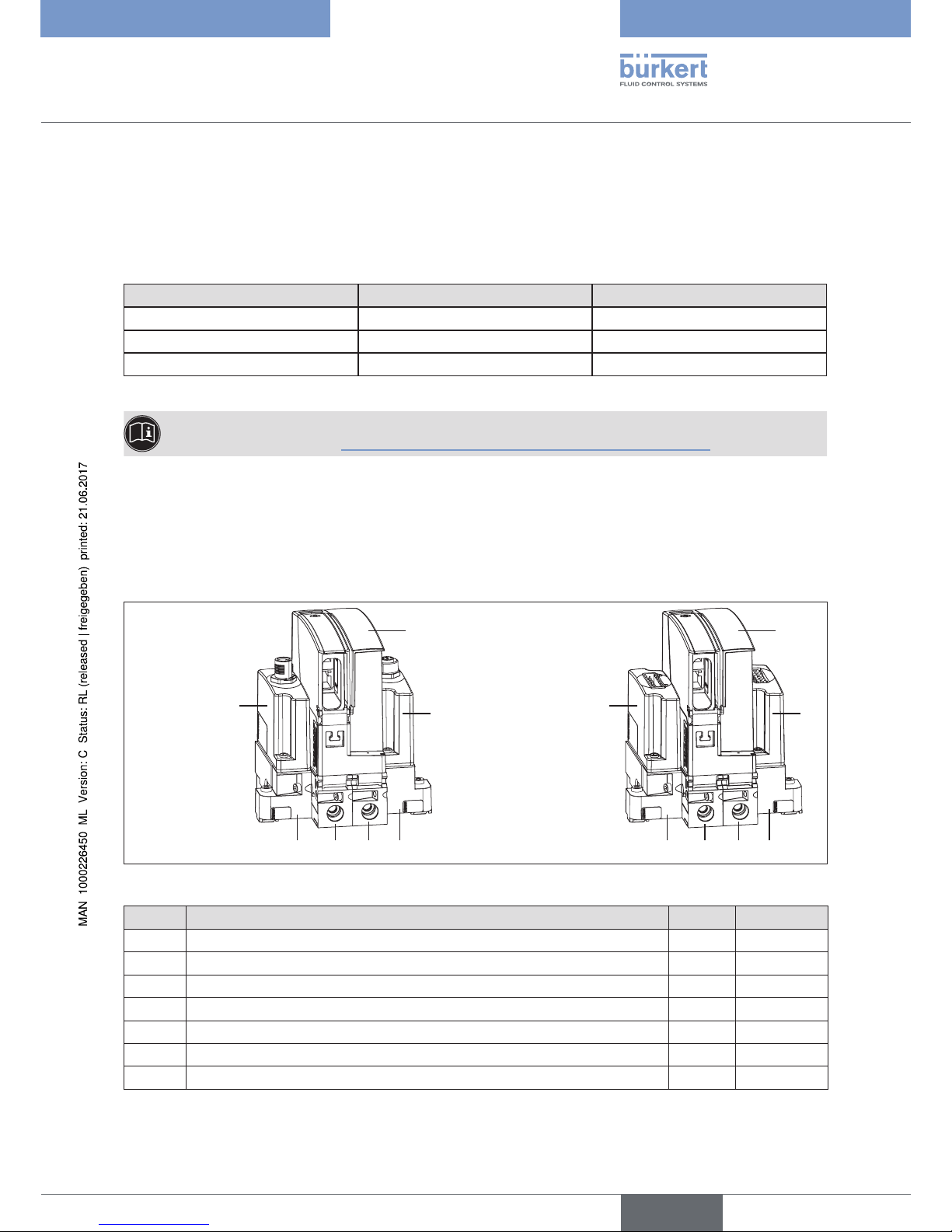
5.1 Possible combinations
The fieldbus gateway Type ME23 can only be operated within a system in combination with additional modules.
For setting up a system comprising several modules, please contact your Bürkert sales office.
In the following, a system in minimum combination is shown as example.
Connection variant:
terminals for cable
gland
Connection variant:
circular plug-in
connector M12
2
4
6 5 5
7
ME23
1
3
6 5 5
7
ME23
Figure 1: Example of a system: Minimum combination of Type ME23 with additional modules
Module Designation Types Order no.
1 Input module (connection variant: circular plug-in connector M12) ME29 00564825
2 Input module (connection variant: terminals for cable gland) ME29 00564826
3 Output module (connection variant: circular plug-in connector M12) ME29 00564827
4 Output module (connection variant: terminals for cable gland) ME29 00564828
5 Backplane for Type ME23 BEF1 00564841
6 Backplane, left BEF1 00564844
7 Backplane, right BEF1 00564846
Table 2: Modules of a possible combination with Type ME23
English
Page 10

10
Technical data
Type ME23
6 TECHNICAL DATA
6.1 Conformity
The fieldbus gateway of Type ME23 conforms to the EC Directives according to the Declaration of Conformity
(if applicable).
6.2 Standards
The applied standards, which are used to demonstrate compliance with the EC Directives, are listed in the EC type
test certificate and/or the EC Declaration of Conformity (if applicable).
6.3 Operating conditions
WARNING!
Risk of injury
Malfunction if used outside.
▶ Do not use Type ME23 outdoors and avoid heat sources which may cause the permissible temperature range
to be exceeded.
Permitted temperatures
Ambient temperature: 0 ... +50 °C
6.4 Industrial Ethernet
Profinet:
Topology recognition LLDP, SNMP V1, MIB2, physical device
Minimum cycle time 1 ms
IRT Support not supported
Media Redundancy MRP client is supported
Additional supported features DCP, VLAN- and priority tagging, Shared Device
Baud rate 100 MBit/s
Data transport layer Ethernet II, IEEE 802.3
Profinet IO specification
V2.3
Multiple Application Relations (AR) The Stack can handle up to 2 IO-ARs, one Supervisor AR and one
Supervisor-DA AR at the same time.
English
Page 11

11
Technical data
Type ME23
Ethernet IP
Predefined standard objects Identity Object (0x01)
Message Router Object (0x02)
Assembly Object (0x04)
Connection Manager (0x06)
DLR Object (0x47)
QoS Object (0x48)
TCP/IP Interface Object (0xF5)
Ethernet Link Object (0xF6)
DHCP supported
BOOTP supported
Baud rates 10 and 100 MBit/s
Duplex modes Half Duplex, Full Duplex, Auto-Negotiation
MDI modes MDI, MDI-X, Auto-MDIX
Data transport layer Ethernet II, IEEE 802.3
Address Conflict Detection (ACD) supported
DLR (ring topology) supported
Integrated switch supported
CIP Reset services Identity Object Reset Service of Type 0 and 1
ModbusTCP
Modbus Function Codes 1, 2, 3, 4, 5, 6, 7, 15, 16, 23
Mode Message Mode: Client, Server
Baud rates 10 and 100 MBit/s
Data transport layer Ethernet II, IEEE 802.3
PROFIBUS
Acyclic communication DP V1 Class 1 Read/Write
DP V1 Class 1 Alarm
DP V1 Class 2 Read/Write/Data Transport
Baud rate Fixed values ranging from 9,6 kBits/s to 12 MBit/s
Auto-detection mode is supported
6.5 Mechanical data
Dimensions: refer to data sheet for Type ME23
Housing material: polycarbonate
English
Page 12
12
Technical data
Type ME23
6.6 Electrical data
Power supply: 18 - 35 V via the backplane BEF1
UL devices: Power supply unit restricted to Class 2
Power consumption < 2 W
Interfaces 2 sockets for RJ45 plug-in connector, for connecting to the fieldbus
1 socket for mini USB connector, for factory service only
Degree of protection: IP 20 according to EN 60529 / IEC 60529
(only if cables, plugs and sockets have been connected correctly)
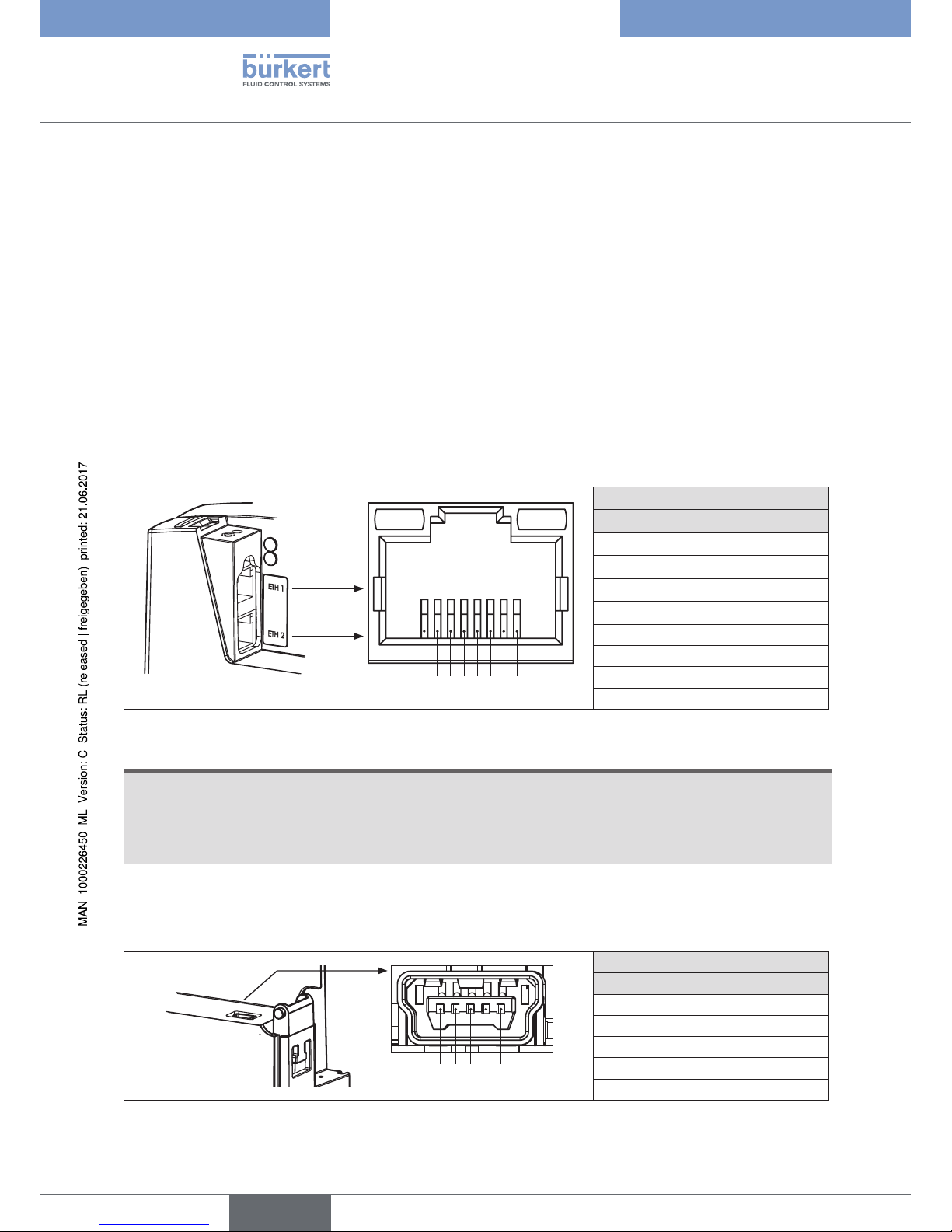
6.6.1 Electrical configuration
Interfaces ETH1 / ETH 2
The two sockets ETH 1 and ETH 2 for RJ45 plug-in connector are equivalent and are used for the connection to
the fieldbus.
1 2 3 4 5 6 7 8
Interface ETH 1 / ETH 2
Pin Plug configuration RJ45
1 TX+
2 TX–
3 RX+
4 Not used
5 Not used
6 RX–
7 Not used
8 Not used
Figure 2: Configuration of interfaces ETH 1 / ETH 2; connection to the fieldbus
NOTE!
To ensure electromagnetic compatibility (EMC)
▶ Only use shielded Ethernet cables.
▶ Connect the Ethernet cables of all participants via the backplane (Type BEF1) to the top hat rail to discharge
the cable shield to ground.
Mini USB interface
The socket for mini USB plugs is intended for factory service only.
1 2 3 4 5
Mini USB interface
Pin Plug configuration
1 5 V
2 D–
3 D+
4 Not used
5 GND
Figure 3: Mini USB interface configuration; for factory service
English
Page 13

13
Installation
Type ME23
7 INSTALLATION
7.1 Safety instructions
WARNING!
Risk of injury from improper installation.
▶ Installation may be carried out only by trained technicians and with the appropriate tools.
▶ Secure system against unintentional activation.
▶ Following installation, ensure a controlled restart.
7.2 Mount Type ME23 on backplane Type BEF1
Fieldbus gateway
Type ME23
Fastening screw
Backplane
Type BEF1
Hinge
Figure 4: Mount fieldbus gateway Type ME23 on backplane Type BEF1
→ Insert hinge part of Type ME23 in counter piece of backplane Type BEF1.
→ Press Type ME23 fully on the backplane Type BEF1.
→ Tighten fastening screw. Max. torque 1 Nm.
The fieldbus gateway ME23 is now connected to the power supply of the backplane Type BEF1.
NOTE!
▶ Use power supply unit with adequate power.
English
Page 14

14
Installation
Type ME23
7.3 Establish network connection to the bus
Fastening screw
Cover
opened
Punched-out recess
for securing the
Ethernet cable
Cover
closed
Figure 5: Establish network connection to the fieldbus.
→ Unscrew fastening screw on the cover of the Type ME23.
→ Open cover.
→ Lead the Ethernet cables through the hole at the back of the cover.
→ Insert the Ethernet cables in the sockets ETH 1 / ETH 2 (for plug-in connector RJ45).
→ Close cover and tighten fastening screw. Max. torque 1 Nm.
The network connection to the fieldbus has now been established.
NOTE!
To ensure electromagnetic compatibility (EMC)
▶ Only use shielded Ethernet cables.
▶ Connect the Ethernet cables of all participants via the backplane (Type BEF1) to the top hat rail to discharge
the cable shield to ground.
Securing the Ethernet cable (strain relief):
For strain relief, a cable clip can be used to secure the Ethernet cables in the punched out recess underneath the
cover.
English
Page 15

15
Start-up
Type ME23
8 START-UP
8.1 Safety instructions
WARNING!
Risk of injury from improper operation.
Improper operation may result in injuries as well as damage to the device and the area around it.
▶ Before start-up, ensure that the operating personnel are familiar with and completely understand the contents
of the operating instructions.
▶ Observe the safety instructions and intended use.
▶ Only adequately trained personnel may start up the equipment/the device.
8.2 Basic settings
The fieldbus gateway Type ME23 can be delivered with a customized basic configuration ex factory.
The büS stick and the "Bürkert Communicator" software, which are available as accessories, are required for
changing the basic configuration or for parameterizing additional process values. See chapter “12 Accessories”
The "Bürkert Communicator" software can also be used for further parameterization of the optionally
available software add-on module user-f(x).
For configuration and parameterization refer to the chapter entitled “10 FUNCTIONS”.
English
Page 16

16
Operation
Type ME23
9 OPERATION
9.1 Safety instructions
WARNING!
Danger due to improper operation.
Improper operation may result in injuries as well as damage to the device and the area around it.
▶ The operating personnel must know and have understood the contents of the operating instructions.
▶ Observe the safety instructions and intended use.
▶ Only adequately trained personnel may operate the equipment/the device.
9.2 Configuration and parameterization of the
Type ME23
The "Bürkert Communicator" software is used for configuration and parameterization of the fieldbus gateway.
The basic configuration and how the most important device-specific parameters for the fieldbus gateway ME23
are set using the "Bürkert Communicator" is described in the following sections of these operating instructions.
See chapter “10 FUNCTIONS”.
The "Bürkert Communicator" software and the general description of the software are available on the Bürkert
homepage.
In addition to the "Bürkert Communicator" software, the büS stick, which is available as accessory,
is required for configuration and parameterization of the fieldbus gateway ME23. See chapter
“12 Accessories”.
9.2.1 Configuration
During configuration, the user initially selects the büS participant that the fieldbus gateway ME23 is to use for
communication with the controller (PLC). After that, he defines which process values are to be converted from
Industrial Ethernet to büS. For description see “10.2 Configuration”, page 23.
9.2.2 Parameterization
During parameterization, the input and output values of the büS participants and of the fieldbus gateway ME23
are assigned to the process values to be converted.
English
Page 17

17
Operation
Type ME23
9.3 Display elements
The LED display elements on the fieldbus gateway ME23 provide information on
• the connection to the control
• the device status
• the network connection
Overview:
LED's for status display
for connection to the control, for
description refer to
chapter “9.3.1”
LED for device status
(colors in accordance with
NAMUR NE 107)
For description refer to
chapter “9.3.2”
LED's
for network connection
For description refer to
chapter “9.3.4”
RJ45
RUN LED
(green)
ERROR LED
(red)
Link/Act LED
(green)
Link LED
(yellow)
Figure 6: Overview of display elements; fieldbus gateway ME23
9.3.1 LED for connection to the control status display
Description:
LED status Description and cause of error Procedure
RUN LED
Active Connection to control active. Not active Connection to control not active. Check cable.
Error LED
Active Connection to control not active. Check cable.
Not active Connection to control active. -
Table 3: Description: Displays of the LED's for the connection to the control
English
Page 18

18
Operation
Type ME23
9.3.2 NAMUR mode
In NAMUR mode, the LED illuminated ring lights up according to NAMUR NE 107, in the color specified for the
device status.
If several device statuses exist simultaneously, the device status with the highest priority is displayed. The priority is
determined by the severity of the deviation from standard operation (red = failure = highest priority).
Displays in NAMUR mode:
Display in accordance
with NE 107
Description Meaning
Color
red Failure, error or
fault
Control mode is not possible due to malfunctioning in the device or
at its peripheral equipment.
orange Function check Work is being carried out at the device; control mode is therefore
not currently possible.
yellow Out of
specification
The ambient conditions or process conditions for the device are
outside the specified area.
Device internal diagnostics point to problems in the device or with
the process properties.
blue Maintenance
required
The device is in controlled operation, however function is briefly
restricted.
→ Maintain device.
green Diagnostics
active
Device is operating faultlessly. Status changes are shown in color.
Messages are transmitted via any connected field bus.
Table 4: Display of device status in NAMUR mode
* A detailed fault description can be found in Chapter “11.3 Display of the device status”
9.3.3 Flashing of the LED illuminated ring
Flashing indicates that a connection to the PC software "Bürkert Communicator" has been established.
English
Page 19

19
Operation
Type ME23
9.3.4 LED for network connection
Description:
LED status Description and cause of error Procedure
Link/Act
LED
(green)
Active Rapid flashing: Connection to the higher-level protocol
layer (PROFINET, EtherNet/IP or Modbus TCP) has been
established. Data is being transmitted.
Slow flashing: No connection to the protocol layer has been
established. This normally occurs for approx. 20 seconds
following a restart.
Not active No connection to the network has been established. Check cable.
Link LED
(yellow)
Active Connection to the network has been established. Not active No connection to the network has been established. Check cable.
Table 5: Description: Displays of the LED's for network connection
English
Page 20

20
Operation
Type ME23
9.4 Removable data storage
The fieldbus gateway Type ME23 has a removable data storage in the size of a micro SD card, on which devicespecific data is stored.
Upon delivery, the micro SD card is inserted in the device.
Using the micro SD card, it is possible to exchange the specific data of devices having the same Ident number. For
example for transmitting the data of a defective device to a new device.
The baud rate, the address and / or the configuration of the process values of the device are, for example, stored
on the micro SD card.
If device-specific data is available on the inserted micro SD card during restart, the device will take over this data.
If no device-specific data is available on the micro SD card, the device will store its own data on it.
NOTE!
Do not use a standard micro SD card for the device. Please order the micro SD card for the Type ME23 via
your Bürkert sales department.
See chapter “12 Accessories”.
Replacing the micro SD card
The micro SD card can be found at the bottom side of the device.
Micro SD card
Figure 7: Replacing the micro SD card; fieldbus gateway ME23
Remove the micro SD card:
→ Press on the edge of the engaged micro SD card to unlock it.
→ Pull micro SD card out.
Insert micro SD card in replacement device:
Make sure you insert the card in the correct orientation.
→ Insert the micro SD card in the card holder of the replacement device.
Make sure that the card clicks in place.
English
Page 21

21
FUNCTIONS
Type ME23
10 FUNCTIONS
10.1 Conversion Industrial Ethernet to büS
The function of the fieldbus gateway is to convert the process values between an Industrial Ethernet control and
büS participants. For this, the fieldbus gateway ME23 must be configured and parameterized.
The "Bürkert Communicator" software and the büS stick, which is available as accessory, are required for
configuration and parameterization of the fieldbus gateway ME23, refer to chapter“12 Accessories”.
The "Bürkert Communicator" software and a general description of it are available on the Bürkert
homepage.
Procedure:
Select the büS participants that are to communicate with the controller (PLC) via the fieldbus gateway
ME23:
PLC
büS participant 1
büS participant 2
Fieldbus gateway
Figure 8: Configuration; selection of the büS participants that are to communicate with the PLC
Select which process values are to be converted from "Industrial Ethernet" to "büS":
PLC
büS participant 1
büS participant 2
Fieldbus gateway
Actual value 1
Actual value 2
Set-point value 1
Set-point value 2
Figure 9: Configuration; selection of the process values that are to be converted from "Industrial Ethernet" to "büS".
English
Page 22

22
FUNCTIONS
Type ME23
Define the direction for transmission of the process values (from/to PLC, from/to büS participant):
The direction is assigned from the perspective of the fieldbus gateway ME23 in the fieldbus büS.
Example:
- Set-point values of a büS participant are the output values of the fieldbus gateway ME23.
- Actual values of a büS participant are the input values of the fieldbus gateway ME23.
Process output values of the PLC are received in the fieldbus gateway ME23 as process input values using
Industrial Ethernet. The process input values are converted and provided as process output values using büS.
Vice versa, process output values of the büS participant are received as büS input values. The process input
values are converted and provided as process output values using Industrial Ethernet.
büS
participant
Fieldbus gateway
Output value Input value
Input value Output value
Output value
Input value
Input value
Output value
Conversion of the process values
Industrial Ethernet büS
Figure 10: Configuration; principle of direction allocation for process values
Based on the type of conversion, büS participants can be addressed directly using their process values and the
direction of conversion.
büS participant
Output value Input value
Input value Output value
Figure 11: Configuration; type of conversion for process values from the PLC to the büS participant
English
Page 23

23
FUNCTIONS
Type ME23
10.2 Configuration
The configuration of the fieldbus gateway ME23 is carried out in the following steps:
- Selection of the büS users and process values which are to communicate with the PLC via the fieldbus
gateway ME23 via “Industrial Ethernet”.
See chapter “10.2.1 Select process data”, page 25.
- Fieldbus-specific address mapping of the objects.
See chapter “10.2.2 Fieldbus-specific address mapping”, page 26
- büS network configuration
See chapter “10.2.3 büS network configuration”, page 28
The device can be delivered with a default basic setting in that specific büS participants and process
values for the conversion have already been defined.
The description of the procedure for the configuration refers to the symbols and terms of "Bürkert Communicator" user interface.
→ Use the “Bürkert büS stick” to connect to the “Bürkert Communicator” software.
→ Add interface: Select tool from tool bar.
→ Select Gateway_01 in the navigation area.
→ Open the menu sub-items.
→ Select Industrial communication function.
→ Select Parameter tab.
→ Select Create Gateway configuration.
File
Edit
View Options
Tools
Desktop
Graph
büS
100%
Help
Gateway_01
FLOWave
Industrial Communication
General settings
Device
MFC_02
MFC_01
-
+
+
+
+
+
-
Industrial communication
Gateway_01
Parameter
Diagnostics
Protocol
Advanced settings
Create Gateway configuration
Download Gateway configuration file
>
>
>
Choose protocol..
MFC_03
ProcessValve_01
COMMUNICATOR
Figure 12: Industrial communication
English
Page 24

24
FUNCTIONS
Type ME23
Desktop
Graph
büS
100%
Gateway_01
FLOWave
Industrial Communication
General settings
MFC_02
MFC_01
-
+
+
+
+
+
-
Industrial communication
Gateway_01
MFC_03
ProcessValve_01
COMMUNICATOR
Parameter Diagnostics
Parameter
Create Gateway configuration
Protocol Selection
CANOpen
DeviceNet
EtherCAT
PROFINET
PROFIBUS
EtherNet/IP
ModbusTCP
Edit existing configuration Start new configuration
File
Edit
View Options
Tools
Help
Device
Figure 13: Create Gateway configuration
→ Select target protocol.
Multiple selection is possible. The configuration files are prepared for the selected protocols based on the
following IO value configuration.
→ Edit existing configuration or Start new configuration.
General settings
Create Gateway configuration
General device settings
Product familie
Product code
Product name
Description
1296380467
Gateway
Gateway_Me23_bueS
ME23
Default network settings
Netmask
Gateway IP-Address
Standard gateway
Advanced
192.168.0.100
255.255.255.0
192.168.0.1
NextCancelBack
Figure 14: General settings
→ Adjust general settings for device description file of the target system (PLC) if required.
→ Click Next.
English
Page 25

25
FUNCTIONS
Type ME23
10.2.1 Select process data
Declare inputs and outputs
Create Gateway configuration
+ Input values
NextCancelBack
* Higlighted entries are available in
the current network.
+ Output values
Gateway_01
Cyclic values
Input_1
Flow rate [l/min]
Name
Value type
i
l/min Input_1
Binary value
Density
Floating point number
Flow rate
Generic number %
Mass flow rate
Mass volumen
Temperature
Velocity
Volume
...
Figure 15: Declare inputs and outputs
→ Process values available in the büS network are highlighted.
→ Add process values to the gateway with drag-and-drop or by double-clicking
(right-clicking adds several values to the same unit).
→ Adjust names. These names appear via the device description file in the target control.
→ Add all required values.
→ Click Next.
English
Page 26

26
FUNCTIONS
Type ME23
10.2.2 Fieldbus-specific address mapping
EtherNet/IP settings
Create Gateway configuration
EthernetIP Data
Order number
Major Revision
EtherNet/IP EDS Revision
1
1.1
Addressing
Automatic EtherNet/IP addressing
NextCancleBack
Minor Revision
7
EtherNet/IP Produkt Typ
Generic Device,keyable (43)
^
Start
Reset device
Cyclic Name Index SubIndex Assembly Connection Class
Input_1 0x2540 0x01 0x65 1
device Status NamurNe107 0x2004 0x01 0x66 2
Control Word 0x3C32 0x01 0x67 2
Figure 16: Fieldbus-specific address mapping
→ Click Start to automatically run object addressing, can be manually adjusted.
→ Click Next.
If several protocols were selected (see “Figure 13: Create Gateway configuration”), the corresponding
protocol-specific settings pages follow.
English
Page 27

27
FUNCTIONS
Type ME23
Final settings
Create Gateway configuration
Select output directory
Create new major version
Output directory
C:\User\Max.Mustermann\AppData\Comuni
FinishCancelBack
Browse
Figure 17: Selecting the output directory
→ Save the configuration files and download to the device. This download runs in the background. (The device
description file is in the subfolder “PLC” under the specified path).
→ Click Finish.
→ Click OK, the window is closed and the device automatically restarts.
The gateway configuration is completed. The connection between control and gateway is established. The
device description file is in the subfolder “PLC” under the specified path.
English
Page 28

28
FUNCTIONS
Type ME23
10.2.3 büS network configuration
→ Use the “Bürkert büS stick” to connect to the “Bürkert Communicator” software.
→ Add interface: Select tool from tool bar.
→ Select interface in the navigation area.
→ Select the büS-Map tab.
Desktop
Graph
büS
100%
Gateway_01
FLOWave
Industrial Communication
General settings
MFC_02
MFC_01
-
+
+
+
+
+
-
MFC_03
ProcessValve_01
COMMUNICATOR
büS
+ -
büS-Map
Overview
Gateway_01
Andere
Actual Flow PR...
Actual Flow 02 01
Actual Flow PR...
Actual Flow 02 02
Setpoint PRO 01
Setpoint 02 01
Setpoint PRO 02
Setpoint 02 02
Flow_Gesamt
ActFlowGas 1
ActFlowGas 2
Anteil_Propan
SetpointGas 1
SetpointGas 2
NamurStatus
MFC_02
Sensor
Actual Flow
Medium Temp.
Current Totalizer
Current Setpoint
Setpoint
Manual Setpoint
Current Dutycycle
Dutycycle
NamurStatus
Regler
Stellglied
Andere
File
Edit
View Options
Tools
Help
Device
Figure 18: büS-Map
→ Parametrize the inputs and outputs with drag-and-drop
(dotted lines mean that there is still no active connection between devices.
Compatible connection points are highlighted in blue).
→ Click Apply changes.
All configured devices are restarted.
English
Page 29

29
FUNCTIONS
Type ME23
10.3 Downloading an existing configuration
If a gateway configuration file (*.bgc) is available, it can be installed on a non-configured device.
→ Use the “Bürkert büS stick” to connect to the “Bürkert Communicator” software.
→ Add interface: Select tool from tool bar.
→ Open the menu sub-items.
→ Select Industrial communication function.
→ Select Parameter tab.
→ Select Download Gateway configuration file.
Desktop
Graph
büS
100%
Gateway_01
FLOWave
Industrial Communication
General settings
MFC_02
MFC_01
-
+
+
+
+
+
-
Industrial Communication
Gateway_01
MFC_03
ProcessValve_01
COMMUNICATOR
Parameter Diagnostics
Parameter
Download Gateway configuration file
Gateway configuration
Load configuration to device
General device settings
Restart
Advanced view
File
Edit
View Options
Tools
Help
Device
Figure 19: Downloading an existing configuration
→ Load device configuration into devices with Load configuration to device.
→ Restart device with Restart.
English
Page 30

30
Maintenance
Type ME23
11 MAINTENANCE
11.1 Safety instructions
WARNING!
Risk of injury from improper maintenance.
▶ Maintenance may be carried out only by trained technicians and with the appropriate tools.
▶ Secure system against unintentional activation.
▶ Following maintenance, ensure a controlled restart.
11.2 Replacing the device
To replace the fieldbus gateways ME23, proceed as follows.
1. Switch off supply voltage.
2. Remove Ethernet cable.
→ If Ethernet cables have been secured at the housing for strain relief, remove securing device.
→ Unscrew fastening screw on the cover of the Type ME23.
→ Open cover.
→ Pull out and remove Ethernet cables from the socket.
Fieldbus gateway
Type ME23
Cover
opened
Backplane
Type BEF1
Fastening screw
for backplane
Fastening screw
for cover
Figure 20: Replacing the device; fieldbus gateway ME23
3. Remove fieldbus gateway Type ME23 from backplane Type BEF1.
→ Unscrew fastening screw on the rear of the housing and remove Type ME23.
English
Page 31

31
Maintenance
Type ME23
4. Replacing the micro SD card
The micro SD card can be found at the bottom side of the device.
Micro SD card
Figure 21: Replacing the micro SD card; fieldbus gateway ME23
Remove the micro SD card:
→ Press on the edge of the engaged micro SD card to unlock it.
→ Pull micro SD card out.
Insert micro SD card in replacement device:
Make sure you insert the card in the correct orientation.
→ Insert the micro SD card in the card holder of the replacement device.
Make sure that the card clicks in place.
5. Mount replacement device
→ Insert hinge part of Type ME23 in counter piece of backplane Type BEF1.
→ Press Type ME23 fully on the backplane Type BEF1.
→ Tighten fastening screw for backplane. Max. torque 1 Nm.
→ Unscrew fastening screw on the cover of the Type ME23.
→ Open cover.
→ Lead the Ethernet cables through the hole at the back of the cover.
→ Insert the Ethernet cables in the sockets ETH 1 / ETH 2 (for plug-in connector RJ45).
→ Close cover and tighten fastening screw. Max. torque 1 Nm.
→ Apply supply voltage.
Securing the Ethernet cable (strain relief):
For strain relief, a cable clip can be used to secure the Ethernet cables in the punched out recess underneath the
cover.
Punched-out recess for securing the Ethernet cable
Figure 22: Strain relief for Ethernet cables; fieldbus gateway ME23
English
Page 32

32
Maintenance
Type ME23
11.3 Display of the device status
The fieldbus gateway ME23 is provided with an LED that displays the device status and changes its color and the
status in accordance with NAMUR NE 107.
If several device statuses exist simultaneously, the device status with the highest priority is displayed. The priority is
determined by the severity of the deviation from standard operation (red LED = error = highest priority).
LED display in accordance
with NAMUR NE 107
Description Procedure
No color No power is supplied to the device. Connect device to power supply.
Flashing rapidly
(applies to all colors)
The device was selected using the
"Bürkert Communicator" software.
De-select the device using the
"Bürkert Communicator" software.
White and illuminated Power is supplied to the device.
A büS connection exists and parameterized büS participants have successfully been found.
-
White and flashing
Red and illuminated Mode 1:
Device defective.
Device requires maintenance –
contact the manufacturer.
Mode 2:
Communication with other büS participants not possible.
Link device to a network with other
büS participants.
Red and flashing Mode 1:
Bus fault (e. g. short-circuit).
Check cable connection.
Mode 2:
The device is not connected to the
PLC.
Check cable connection.
Consult device description regarding
connection of the device in PLC.
Mode 3:
The device cannot find the assigned
büS participant.
Make sure the büS participant is
affected to the device.
Orange and illuminated Mode 1:
Device temperature is outside the
specification, destruction of the device
cannot be excluded.
Operate the device inside the
specification.
Mode 2: Device has detected an error
in the fieldbus büS.
Restart the network if the device
status lasts longer than 5 seconds.
Orange and flashing Mode 1:
Search for büS participant active.
Mode exit after a few seconds.
Restart the network if the device
status lasts longer than 4 minutes.
Mode 2: Device has detected an error
in the fieldbus büS.
Restart device.
Yellow and illuminated
Blue and illuminated
Green and illuminated
Table 6: Description: LED display of device status and procedures
English
Page 33

33
Maintenance
Type ME23
LED status Description and cause of error Procedure
RUN LED
Active Connection to control active. Not active Connection to control not active. Check cable.
Error LED
Active Connection to control not active. Check cable.
Not active Connection to control active. -
Table 7: Description: Displays of the LED's for the connection to the control
LED status Description and cause of error Procedure
Link/Act
LED
Active Rapid flashing: Connection to the higher-level pro-
tocol layer (PROFINET, EtherNet/IP or Modbus TCP)
has been established. Data is being transmitted.
Slow flashing: No connection to the protocol layer
has been established. This normally occurs for
approx. 20 seconds following a restart.
Not active No connection to the network has been established. Check cable.
Link LED
Active Connection to the network has been established. Not active No connection to the network has been established. Check cable.
Table 8: Description: Displays of the LED's for network connection
English
Page 34

34
Maintenance
Type ME23
11.4 Troubleshooting
Problem Possible cause Procedure
The NAMUR-LED goes off
periodically.
The power supply collapses periodically – the device implements a reset
each time.
Use power supply with adequate
power.
The drop in power in the connecting
cable is too great.
Increase cable cross-section.
Reduce cable length.
No process values are transmitted between Industrial Ethernet and büS.
No cable connection. Check Ethernet and büS cable
connection.
Reading and writing of the values has
not been allowed by the PLC in the
control object of the participant.
Allow reading and writing of the values
in the control object of the participant.
The process values have been
configured incorrectly.
Check configuration of the process
values.
The process values have been
allocated incorrectly.
Check allocation of the process values
to the büS participants.
The process values cannot
be allocated to the büS
participants.
The process values have not been
configured.
Check configuration of the process
values.
Takeover of the configuration must
be completed by a restart of the
participant.
Restart the participant after
configuration.
The process values have been allocated to different classes.
Check allocation to ensure that büS
participants work with process values
of the same class.
Observe input and output direction
as allocation.
Verify that direction of input and output
is correct.
An incorrect value is transmitted or value is zero.
The process values have not been
allocated or have been allocated to
the wrong participants.
Check allocation of the process values.
Replacement device fails to
take over values from micro SD
card from the defective device.
The device Ident number of the
replacement device and the defective
device differ.
Values can only be transmitted
between devices having the same Ident
number.
The micro SD card is defective. The
device was unable to write any values
on the micro SD card.
Replace the micro SD card (refer to
chapter “12 Accessories”) and retry
transmitting the parameters of the
defective device to the card (refer
to chapter “9.4 Removable data
storage”).
Replacement device fails to take
over all values from micro SD
card from the defective device.
The EDS device description between
the replacement device and the
defective device differs.
Only the existing values of the defective
device can be transferred to the
replacement device. New values of the
replacement device must be parameterized using the "Bürkert Communicator"
software.
Table 9: Troubleshooting
English
Page 35

35
Accessories
Type ME23
12 ACCESSORIES
CAUTION!
Risk of injury and/or damage by the use of incorrect parts.
Incorrect accessories and unsuitable spare parts may cause injuries and damage the device and the surrounding area.
▶ Use original accessories and original spare parts from Bürkert only.
Accessories Order no.
büS Stick set (including power supply unit) and "Bürkert Communicator" software 00772426
Micro SD card on request
English
Page 36

36
Packaging and transport
Type ME23
13 PACKAGING AND TRANSPORT
NOTE!
Transport damage.
Inadequately protected devices may be damaged during transportation.
• Protect the device against moisture and dirt in shock-resistant packaging during transportation.
• Prevent the temperature from exceeding or dropping below the permitted storage temperature.
14 STORAGE
NOTE!
Incorrect storage may damage the device.
• Store the device in a dry and dust-free location.
• Storage temperature: -25...+60 °C.
15 DISPOSAL
NOTE!
Damage to the environment caused by parts contaminated with media.
• Dispose of the device and packaging in an environmentally friendly manner.
• Observe applicable disposal and environmental regulations.
Observe the national waste disposal regulations.
English
Page 37

Page 38

www.burkert.com
 Loading...