

Page 1
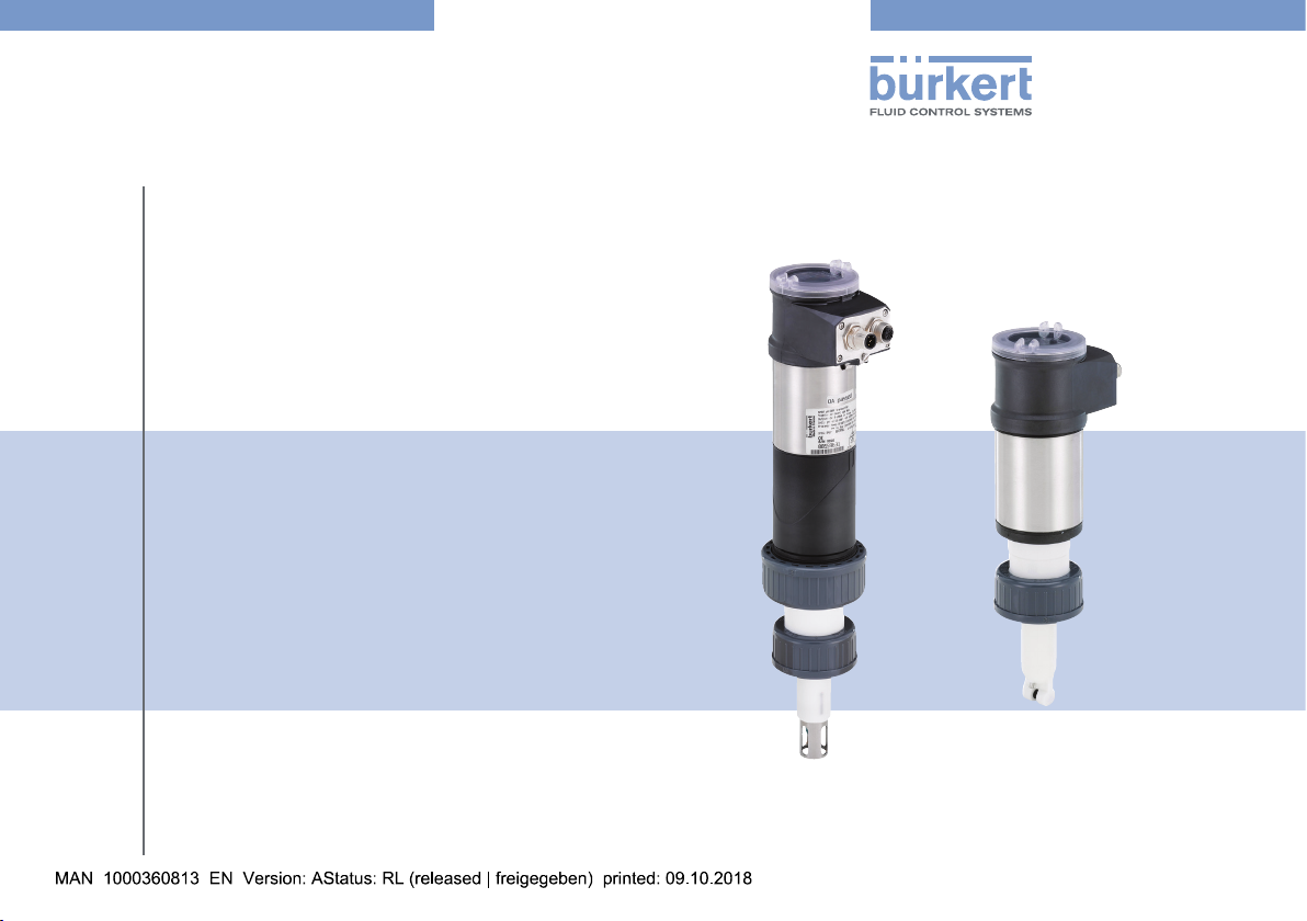
Types 8202 / 8222
ELEMENT
pH / Redox or conductivity meter
pH- / Redox- oder Leitfähigkeits-Messgerät
pH / Redox-mètre ou conductivimètre
Quickstart
English / Deutsch / Français
Page 2
We reserve the right to make technical changes without notice.
Technische Änderungen vorbehalten.
Sous réserve de modification technique.
© Bürkert SAS, 2012 - 2018
Quickstart 1809/05_EU-ML 00567367 / ORIGINAL_FR
Page 3
Type 8202/8222
Contents
1 ABOUT THIS QUICKSTART ....................................................................4
1.1 Definition of the word “device” ............................................... 4
1.2 Validity of the quickstart ........................................................... 4
1.3 Symbols used ............................................................................. 4
2 INTENDED USE .............................................................................................5
3 BASIC SAFETY INFORMATION ............................................................6
4 GENERAL INFORMATION ........................................................................7
4.1 Contact ........................................................................................ 7
4.2 Warranty conditions .................................................................. 7
4.3 Information on the internet ...................................................... 7
5 DESCRIPTION OF THE RATING PLATE ............................................8
6 TECHNICAL DATA ........................................................................................9
6.1 Conditions of use ...................................................................... 9
6.2 Conformity to standards and directives ............................... 9
6.3 Dimensions of devices ...........................................................10
6.4 Mechanical data.......................................................................10
6.5 Fluid data ...................................................................................11
6.6 Electrical data ...........................................................................14
6.7 Data of connectors and cables ............................................15
6.8 pH/Redox probe of the 8202 ...............................................16
6.9 Sensor specifications of the 8222 ......................................16
7 ASSEMBLY ....................................................................................................16
7.1 Safety instructions ...................................................................16
7.2 Install the display module ......................................................16
7.3 Install the pH or redox probe in the sensor holder of the
8202 (without fluid) .............................................................................17
7.4 Mounting the electronic module to the sensor holder of
the 8202 (without fluid) ......................................................................18
8 INSTALLATION ............................................................................................ 19
8.1 Safety instructions ...................................................................19
8.2 Installation of the 8202 onto the pipe ................................19
8.3 Installation of the 8222 onto the pipe ................................22
8.4 Wiring.........................................................................................24
9 ADJUSTMENT AND COMMISSIONING .........................................28
9.1 Safety instructions ...................................................................28
9.2 Using the navigation button ..................................................29
9.3 Using the dynamic functions.................................................31
9.4 Knowing the display ................................................................31
9.5 Knowing the operating levels ...............................................33
9.6 Knowing the Process level ....................................................34
9.7 Choosing the output wiring mode .......................................35
9.8 Setting the probe parameters of the 8202 .......................35
9.9 Activating/deactivating the Hold function ..........................35
9.10 Calibrate the pH or redox probe (8202) ............................35
9.11 Calibrating the sensor of the 8222 .....................................37
10 PACKAGING, TRANSPORT .................................................................. 38
11 STORAGE ......................................................................................................38
12 DISPOSAL OF THE DEVICE ................................................................ 38
English
3
Page 4
Type 8202/8222
About this quickstart
1 ABOUT THIS QUICKSTART
This quickstart describes the entire life cycle of the device. Please
keep this quickstart in a safe place, accessible to all users and any
new owners.
This quickstart contains important safety information.
Failure to comply with these instructions can lead to hazardous
situations. Pay attention in particular to the chapters „Basic safety
information“ and „Intended use“.
▶ Irrespective of the version of the device, this quickstart must be read
and understood.
The quickstart explains how to install, adjust, and start-up the device.
A detailed description of the device can be found in the related
operating instructions.
The operating instructions for the device can be found on the
Internet at: www.burkert.com
1.1 Definition of the word “device”
The word “device” used within this quickstart refers to:
• the Type 8202 ELEMENT pH-meter and redox-meter or
• the Type 8222 ELEMENT conductivity meter.
1.2 Validity of the quickstart
This quickstart is valid for the following devices:
• Type 8202 ELEMENT pH-meter and redox-meter, version V2,
• Type 8222 ELEMENT conductivity meter, version V2.
These informations are available on the rating plate, see chap. 5.
1.3 Symbols used
Danger
Warns against an imminent danger.
▶ Failure to observe this warning results in death or in serious
injury.
Warning
Warns against a potentially dangerous situation.
▶ Failure to observe this warning can result in serious injury or
even death.
CaUTiOn
Warns against a possible risk.
▶ Failure to observe this warning can result in substantial or minor
injuries.
nOTiCe
Warns against material damage.
4
English
Page 5
Type 8202/8222
Intended use
Advice or important recommendations.
Refers to information contained in this quickstart or in other
documents.
▶ Indicates an instruction to be carried out to avoid a danger, a
warning or a possible risk.
→ Indicates a procedure to be carried out.
2 INTENDED USE
Use of this device that does not comply with the instructions
could present risks to people, nearby installations and the
environment.
The Type 8202 ELEMENT pH-meter and redox-meter is intended
solely for the measurement of:
- the pH in clean liquids or liquids containing solids, sulphides
or proteins.
- or the oxidation reduction potential (ORP) in clean liquids or
liquids containing solids, sulphides or proteins which may
present low conductivity.
The Type 8222 ELEMENT conductivity meter is intended for the
measurement of the conductivity.
▶ Use this device in compliance with the characteristics and
commissioning and use conditions specified in the contractual
documents and in the Operating Instructions.
▶ Never use this device for security applications.
▶ Protect this device against electromagnetic interference, ultra-
violet rays and, when installed outdoors, the effects of climatic
conditions.
▶ Use this device only if in perfect working order.
▶ Requirements for the safe and proper operation of the device
are proper transport, storage and installation, as well as careful
operation and maintenance.
▶ Only use the device as intended.
English
5
Page 6
3 BASIC SAFETY INFORMATION
This safety information does not take into account any contingencies
or occurrences that may arise during installation, use and maintenance of the device.
The operating company is responsible for the respect of the local
safety regulations including staff safety.
Risk of injury due to electrical voltage.
▶ Shut down the electrical power source of all the conductors and
isolate it before carrying out work on the system.
▶ If a 12...36 V DC or a 14...36 V DC powered version is installed
either in a wet environment or outdoors, all the electrical voltages must be of max. 35 V DC.
▶ All equipment connected to the device must be double insu-
lated with respect to the mains according to the standard IEC
61010-1:2010.
▶ Observe all applicable accident protection and safety regula-
tions for electrical equipment.
Risk of injury due to high pressure in the installation.
▶ Stop the circulation of fluid, cut off the pressure and drain the
pipe before loosening the process connections.
Risk of burns due to high fluid temperatures.
▶ Use safety gloves to handle the device.
▶ Stop the circulation of fluid and drain the pipes before loosening
the process connections.
Type 8202/8222
Basic safety information
Risk of injury due to the nature of the fluid.
▶ Respect the prevailing regulations on accident prevention and
safety relating to the use of dangerous fluids.
Various dangerous situations.
To avoid injury take care:
▶ not to use the device in explosive atmospheres.
▶ not to use the device in an environment incompatible with the
materials it is made of.
▶ not to use fluid that is incompatible with the materials the device
is made of.
▶ not to subject the device to mechanical loads.
▶ not to make any modifications to the device.
▶ to prevent any unintentional power supply switch-on.
▶ to carry out the installation and maintenance work by qualified
and skilled staff with the appropriate tools.
▶ to guarantee a defined or controlled restarting of the process,
after a power supply interruption.
▶ to observe the general technical rules when installing and using
the device.
6
English
Page 7
Type 8202/8222
General information
nOTiCe
The device may be damaged by the fluid in contact with.
▶ Systematically check the chemical compatibility of the com-
ponent materials of the device and the fluids likely to come
into contact with the materials (for example: alcohols, strong
or concentrated acids, aldehydes, alkaline compounds, esters,
aliphatic compounds, ketones, halogenated aromatics or hydrocarbons, oxidants and chlorinated agents).
nOTiCe
Elements / Components sensitive to electrostatic discharges
▶ This device contains electronic components that are sensitive
to electrostatic discharges. They may be damaged if they are
touched by an electrostatically charged person or object. In the
worst case scenario, these components are instantly destroyed
or disabled as soon as they are activated.
▶ To minimise or even avoid any damage caused by an elec-
trostatic discharge, take all the precautions described in the
EN 61340-5-1 norm.
▶ Also make sure that you do not touch any of the live electrical
components.
4 GENERAL INFORMATION
4.1 Contact
To contact the manufacturer of the device, use following address:
Bürkert SAS
Rue du Giessen
BP 21
F-67220 TRIEMBACH-AU-VAL
You may also contact your local Bürkert sales office.
The addresses of our international sales offices are available on the
internet at: www.burkert.com
4.2 Warranty conditions
The condition governing the legal warranty is the conforming use of
the device in observance of the operating conditions specified in the
Operating Instructions.
4.3 Information on the internet
You can find the Operating Instructions and technical data sheets
for Type 8202 and for Type 8222 at: www.burkert.com
English
7
Page 8
Type 8202/8222
1
8
10
12
11
Description of the rating plate
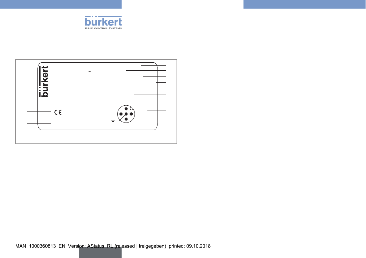
5 DESCRIPTION OF THE RATING
PLATE
8202 pH/ORP Transmitter V2
Supply: 14-36V 40W Max
Output: 1x 4-20mA 2x Trans 1A Max
Cell: pH -2/16 ORP +-2V 120mm PG13.5
Process: Temp 0/50°C limited by cell
PN 16 Bar limited by cell
Made in France
IP65 -IP67 W41MT
9
Fig. 1: Rating plate of the device Type 8202 (example)
S-N:3054
00559630
2:NPN/PNP1
3:0V
4:NPN/PNP2
1:V+
2
3
4
5
6
7
1. Type of the device, measured variable and version
2. Electrical power supply and power consumption
3. Output specifications
4. Sensor specifications
5. Temperature range of the fluid, without sensor
6. Nominal pressure of the fluid, without sensor
7. Allocation of the pins on the M12 fixed connectors
8. Construction code
9. Article number
10. Serial number
11. Conformity marking
12. Protection rating
8
English
Page 9
Type 8202/8222
Technical data
6 TECHNICAL DATA
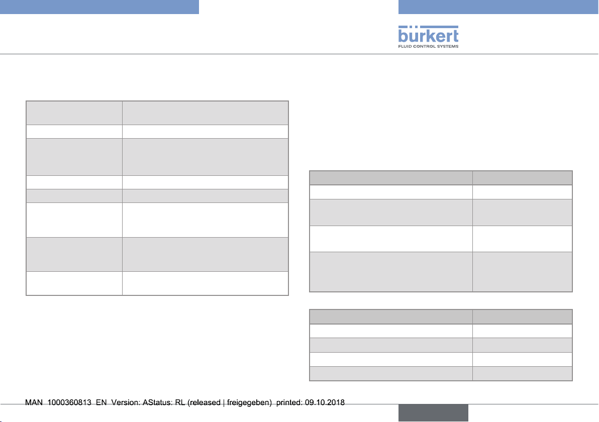
6.1 Conditions of use
Ambient temperature
Air humidity
Protection rating
according to
EN 60529
Operating conditions
Equipment mobility
Degree of pollution
(UL and CSA recognized version)
Installation category
(UL and CSA recognized version)
Max. height above
sea level
–10...+60 °C (without pH or redox probe
for the 8202)
< 85%, non condensing
IP65 and IP67 with connectors plugged
in and tightened and electronic module
cover fully sealed
Continuous
Fixed
Degree 2 according to EN 61010 -1
Category I according to UL 61010-1 Indoor use
2000 m
6.2 Conformity to standards and directives
The applied standards, which verify conformity with the EU directives, can be found on the EU-type examination certificate and/or the
EU declaration of conformity (if applicable).
6.2.1 Conformity to the Pressure Equipment
Directive
→ Make sure the device materials are compatible with the fluid.
→ Make sure the pipe DN and the PN are adapted for the device.
The device conforms to Article 4, Paragraph 1 of the Pressure
Equipment Directive 2014/68/EU under the following conditions:
• Device used on a piping (PS = maximum admissible pressure;
DN = nominal diameter of the pipe)
Type of fluid Conditions
Fluid group 1, Article 4, Paragraph 1.c.i DN≤25
Fluid group 2, Article 4, Paragraph 1.c.i
Fluid group 1, Article 4, Paragraph 1.c.ii
Fluid group 2, Article 4, Paragraph 1.c.ii
• Device used on a vessel (PS = maximum admissible pressure)
Type of fluid Conditions
Fluid group 1, Article 4, Paragraph 1.a.i PS ≤ 200 bar
Fluid group 2, Article 4, Paragraph 1.a.i PS ≤ 1000 bar
Fluid group 1, Article 4, Paragraph 1.a.ii PS ≤ 500 bar
Fluid group 2, Article 4, Paragraph 1.a.ii PS ≤ 1000 bar
DN≤32
or PSxDN≤1000
DN≤25
or PSxDN≤2000
DN≤200
or PS≤10
or PSxDN≤5000
English
9
Page 10
Type 8202/8222
Measuring
Equipment
EXXXXXX
®
Technical data
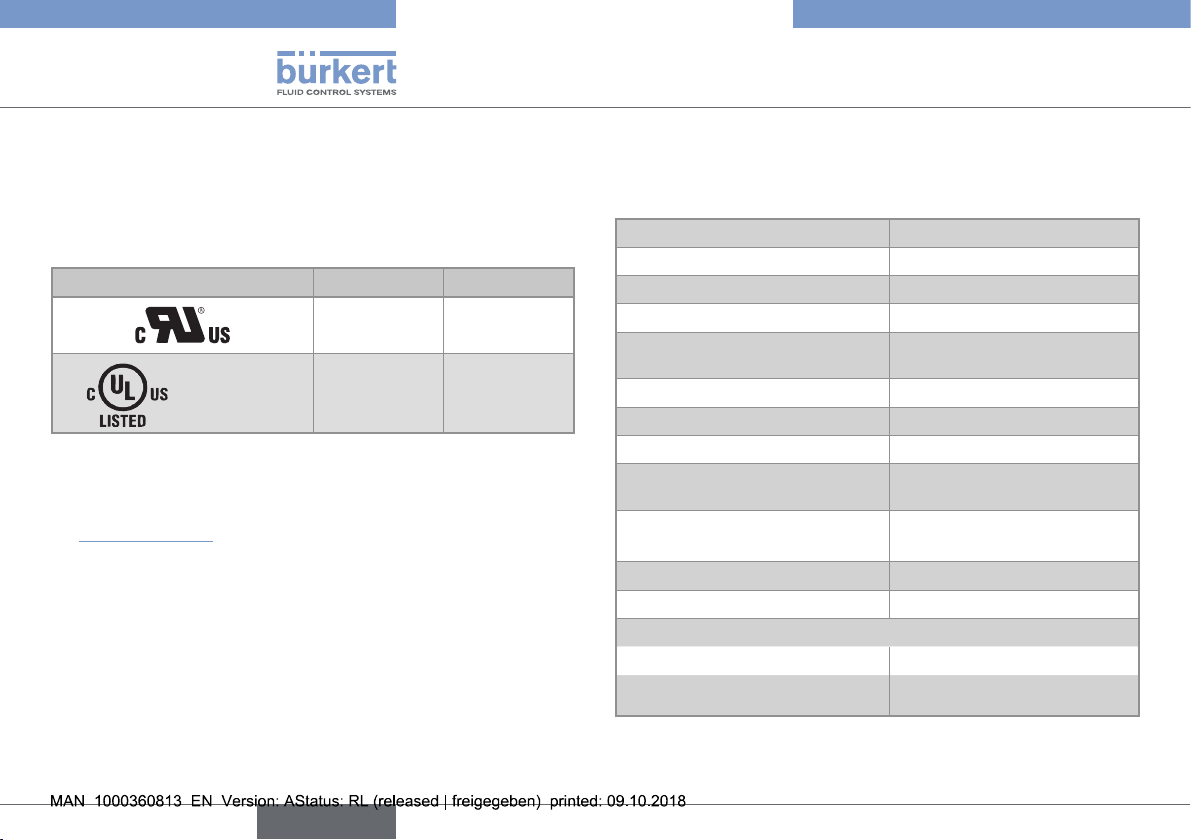
6.2.2 UL certification
The devices with variable key PU01 or PU02 are UL certified
devices and comply also with the following standards:
• UL 61010-1
• CAN/CSA-C22.2 n°61010-1
Identification on the device Certification Variable key
UL recognized PU01
UL listed PU02
6.3 Dimensions of devices
→ Please refer to the technical data sheets related to the device at:
www.burkert.com
6.4 Mechanical data
Table 1: Materials used in the device Type 8202 (without the
probe) or the device Type 8222
Part Material
Box / seals stainless steel, PPS / EPDM
Cover / seal PC / silicone
Display module PC / PBT
M12 fixed connector nickel-plated brass (stainless
steel on request)
Fixed connector holder stainless steel 1.4404 (316L)
Screws stainless steel
Nut PVC or PVDF
Sensor holder / seal of the 8202 (*) PVDF, stainless steel 1.4571
(316Ti) / EPDM
pH or Redox probe of the 8202 refer to the related Operating
Instructions
Conductivity sensor of the 8222 (*) PVDF
Pt1000 of the 8222 (*) stainless steel 1.4571 (316Ti)
Electrodes of the 8222
• sensor C=1 • graphite
• sensor C=0.1 or C=0.01 • stainless steel 1.4571
(316Ti)
(*) in contact with the fluid
10
English
Page 11
Type 8202/8222
Technical data
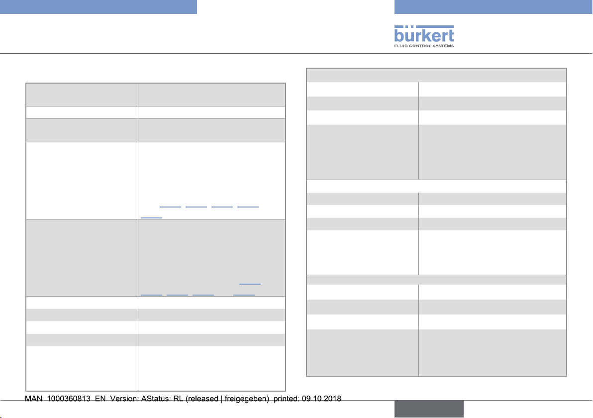
6.5 Fluid data
Pipe diameter
Type of fitting
Nut between the device
and the fitting
Max. fluid temperature
Max. fluid pressure
pH measurement (8202)
• Measurement range • 2...16 pH or –580...+580 mV
• Resolution • 0.001 pH or 0.1 mV
• Measurement deviation • ±0.02 pH or 0.5 mV
• Recommended min.
divergence of the pH
range associated to the
4...20 mA signal
DN25 to DN110 (DN15 to DN20
under specific conditions)
Adapter S022
G 1 1/2'' internal thread
The fluid temperature may be
restricted by the probe used (see
the related Operating Instructions),
by the pressure of the fluid and
the material of the S022 adapter
(see Fig. 2, Fig. 3, Fig. 4, Fig. 5 and
Fig. 6)
PN16
The fluid pressure may be restricted
by the probe used (see the related
Operating Instructions), by the temperature of the fluid and the material
of the adapter S022 (see Fig. 2,
Fig. 3, Fig. 4, Fig. 5 and Fig. 6)
• 0.5 pH unit or 30 mV (e.g.: range
6,7...7,2 pH or –20...+10 mV
associated to the 4...20 mA output
current)
Redox potential measurement (8202)
• Measurement range • –2000...+2000 mV
• Resolution • 1 mV
• Measurement deviation • ±3 mV
• Recommended min.
divergence of the redox
potential range associated to the 4...20 mA
signal
Conductivity measurement (8222)
• Measurement range • 0,05 µS/cm...10 mS/cm
• Resolution • 1 nS/cm
• Measurement deviation • ±3 % of the measured value
• Recommended min. divergence of the conductivity
range associated to the
4...20 mA signal
Temperature measurement
• Measurement range • –40...+130 °C
• Resolution • 0.1 °C
• Measurement deviation • ±1 °C
• Recommended min. divergence of the temperature
range associated to the
4...20 mA signal
• 50 mV (e.g.: range
1550...1600 mV associated to the
4...20 mA output current)
• 2 % of the full scale (e.g. for the
sensor with C=0.1: range from
100...104 µS corresponds to the
4...20 mA output current)
• 10 °C (e.g. range +10...+20 °C
corresponds to the 4...20 mA
output current)
English
11
Page 12
Type 8202/8222
Technical data
Temperature probe
Temperature compensation (8202)
Temperature compensation (8222)
• Pt1000 integrated in the sensor
holder (8202)
• Pt1000 integrated in the conductivity sensor (8222)
Automatic (integrated Pt1000),
Reference temperature = 25°C
• none or
• according to a predefined graph
(NaCl or ultra pure water) or
• according to a graph defined
especially for your process
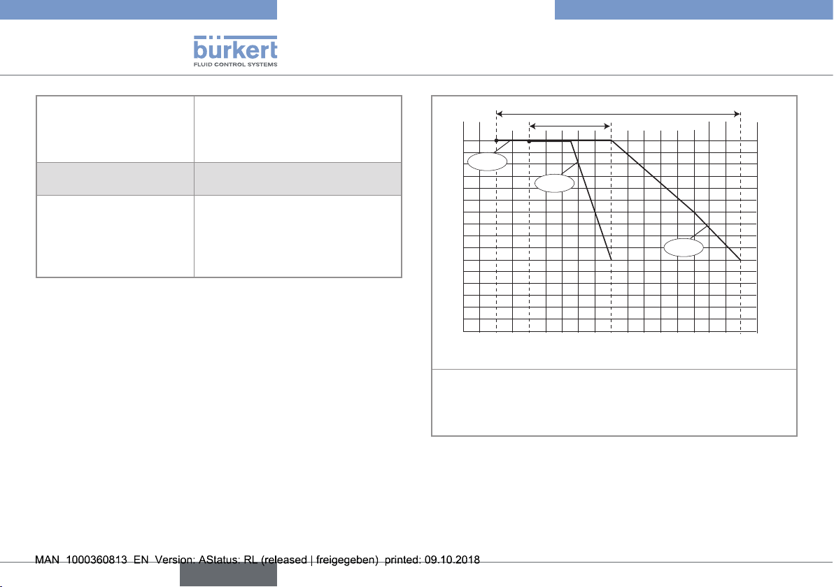
A
PVDF
+140
T ( ° C)
P (bar)
16
15
14
13
12
11
10
B
PVDF
PVC
9
8
7
6
5
4
3
2
1
0
-20 0 +20 +40 +60 +80 +100 +120
A: application range of a 8202 with a PVDF nut
B: application range of a 8202 with a PVC nut
The measures have been made at an ambient temperature of 60 °C
Fig. 2: Fluid temperature / fluid pressure dependency of the 8202
(without the probe) with a PVC or PVDF nut
P (psi)
232
217.6
203
188.6
174
159.6
145
130.6
116
101.6
87
72.5
58
43.5
29
14
0
12
English
Page 13

Type 8202/8222
Technical data
A
P (bar)
16
15
14
13
12
11
10
PVDF
9
8
7
6
5
4
3
2
1
0
-20 0 +20 +40 +60 +80 +100 +120
B
PVC
PVDF
A: application range of a 8222 with a PVDF nut
B: application range of a 8222 with a PVC nut
The measures have been made at an ambient temperature of 60 °C
Fig. 3: Fluid temperature / fluid pressure dependency of the 8222 with a
PVC or PVDF nut
P (psi)
232
217.6
203
188.6
174
159.6
145
130.6
116
101.6
87
72.5
58
43.5
29
14
0
T ( ° C)
16
P (bar)
15
14
13
12
11
10
9
8
7
6
5
4
3
2
1
0
-20
PVC + PP
Metal
0 +20 +40 +60
232
217.6
203
188.6
174
159.6
145
130.6
116
101.6
87
72.5
58
43.5
29
14
0
T (°C)
P (psi)
Fig. 4: Fluid temperature / fluid pressure dependency of the 8202
(without the probe) or the 8222, with a PVC nut and a metal, PVC
or PP S022 adapter
P (bar)
16
15
14
13
12
11
10
9
8
PVC + PP
7
6
5
4
3
2
1
0
-20 0 +20 +40 +60 +80 +100 +140
PVC
PP
Metal
+120
232
217.6
203
188.6
174
159.6
145
130.6
116
101.6
87
72.5
58
43.5
29
14
0
P (psi)
T (°C)
Fig. 5: Fluid temperature / fluid pressure dependency of the 8202
(without the probe) with a PVDF nut and a metal, PVC or PP S022
adapter
English
13
Page 14

Type 8202/8222
Technical data
P (bar)
16
15
14
13
12
11
10
9
8
PVC + PP
7
6
5
4
3
2
1
0
-20 0 +20 +40 +60 +80 +100 +140
PVC
PP
Metal
+120
232
217.6
203
188.6
174
159.6
145
130.6
116
101.6
87
72.5
58
43.5
29
14
0
P (psi)
T (°C)
Fig. 6: Fluid temperature / fluid pressure dependency of the 8222, with a
PVDF nut and a metal, PVC or PP S022 adapter
6.6 Electrical data
Power supply
• Version with 3 outputs • 14...36 V DC, filtered and regulated
• Version with 4 outputs • 12...36 V DC, filtered and regulated
Characteristics of the
power source (not supplied) of the UL versions
Current consumption
• Version with 3 outputs • 25 mA max. (at 14 V DC)
• Version with 4 outputs • 5 mA max. (at 12 V DC)
Current consumption,
with loads on the
transistors
Power consumption
Protection against polarity
reversal
Protection against voltage
spikes
Protection against short
circuits
• limited power source according to
§9.4 of EN 61010-1 standard
• or class 2 source according to
UL 1310/1585 and EN 60950-1
standards
1 A max.
40 W max.
yes
yes
yes, transistor outputs
14
English
Page 15

Type 8202/8222
Technical data
Transistor output
Current output
• Response time (10 %
- 90 %)
• Version with 1 current
output
• Version with 2 current
outputs
NPN (/sink) or PNP (/source)
(depending on software setting),
open collector, 700 mA max., 0.5 A
max. per transistor if both transistor
outputs are wired.
NPN output: 0.2...36 V DC
PNP output: supply voltage
4...20 mA, sink ("NPN sink") or
source ("PNP source") (depending
on software setting)
• 150 ms (default value)
• max. loop impedance: 1100W
at 36 V DC, 610W at 24 V DC,
180W at 14 V DC
• max. loop impedance: 1100W
at 36 V DC, 610W at 24 V DC,
100W at 12 V DC
6.7 Data of connectors and cables
Number of fixed
connectors
1 male M12 fixed
connector
1 male M12 fixed
connector and 1
female M12 fixed
connector
Type of connector
5-pin female M12 connector (not supplied).
For the M12 connector with article number
917116, use a shielded cable:
• diameter: 3...6.5 mm
• wire cross section: max. 0.75 mm
5-pin female M12 connector (not sup-
plied) and 5-pin male M12 connector (not
supplied).
For the M12 connector with article number
917116, use a shielded cable:
• diameter: 3...6.5 mm
• wire cross section: max. 0.75 mm
2
2
English
15
Page 16

Type 8202/8222
Assembly
6.8 pH/Redox probe of the 8202
The pH or redox probe must satisfies the following specifications:
• combined probe;
• length: 120 mm;
• with PG 13.5 head;
• with an S7/S8 fixed connector;
• without temperature probe.
The specifications of the probe can be found in the Operating Instructions of the probe used.
6.9 Sensor specifications of the 8222
Conductivity sensor C=0.01
• Measurement range • 0.05...20 µS/cm
• Type of fluid • ultra-pure water, pure water
Conductivity sensor C=0.1
• Measurement range • 0.5...200 µS/cm
• Type of fluid • pure water, industrial wastewater
Conductivity sensor C=1
• Measurement range • 5 µS/cm...10 mS/cm
• Type of fluid • industrial wastewater, wastewater
7 ASSEMBLY
7.1 Safety instructions
Warning
Risk of injury due to non-conforming assembly.
▶ The device must only be assembled by qualified and skilled staff
with the appropriate tools.
Risk of injury due to unintentional switch on of power supply
or uncontrolled restarting of the installation.
▶ Avoid unintentional activation of the installation.
▶ Guarantee a set or controlled restarting of the process subse-
quent to any intervention on the device.
7.2 Install the display module
nOTiCe
The tightness of the device is not guaranteed when the cover
is removed.
▶ Prevent the projection of liquid inside the housing.
The device may be damaged if a metal component comes
into contact with the electronics.
▶ Prevent contact of the electronics with a metallic item.
16
English
Page 17

Type 8202/8222
1
Assembly
a)
b)
20°
→ Remove the cover.
→ Set the display module
at an angle of ca. 20° in
relation to the desired
position.
The module can be fitted in
4 different positions, at 90°
intervals.
c)
d)
→ Fully push in the module
and turn clockwise to
lock it.
→ Check that there is a
seal on the housing and
2
that it is not damaged.
Replace it if necessary.
→ Grease the seal if nec-
essary, using a component compatible with
the seal material.
→ [1] Set the cover to
ensure that the 4
grooves of the cover
match with the 4 pins of
the housing.
→ [2] Turn the cover
clockwise with an angle
of about 15° to lock it.
Fig. 7: Mounting the display module
7.3 Install the pH or redox probe in the sensor holder of the 8202 (without fluid)
Following instructions are valid for a Bürkert probe.
If you use a probe from another supplier, respect the related
Operating Instructions.
English
17
Page 18

Type 8202/8222
Assembly
probe head
H
compression washer
→ Remove the protective
plugs.
→ Check that dimension H on
seal
A
the probe is between
34 and 46mm. If necessary,
adjust the height of the
compression washer.
→ At first use, apply water
or soapy water on the "A"
seal.
→ Insert the seal into the
groove on the holder.
→ Insert the probe with its
seal into the holder from
above.
7.4 Mounting the electronic module to the sensor holder of the 8202 (without fluid)
→ Check that the pH or redox probe is mounted into the sensor
holder.
→ Check that seal "A" on the
holder is in good condition.
Replace it if necessary.
→ Clean connectors "B" and
"C" for connection of the pH/
redox probe with alcohol to
avoid measurement errors.
→ Insert the electronic module
into the holder, making sure
the polarising slots are correctly positioned.
→ Apply slight vertical pressure
C
to engage the seal.
→ Tighten the probe head
using a suitable wrench.
A
B
Fig. 8: Mounting the probe into the holder of the 8202 (without fluid)
18
English
Page 19

Type 8202/8222
Installation
→ Fasten the electronic module
and the holder together by
tightening the G2'' nut.
→ Tighten the G2'' nut by hand
only, until it stops turning,
to ensure good electrical
contact.
Fig. 9: Mounting the electronic module to the holder, without fluid (8202)
→ Mounting the display module.
→ Calibrate the device.
8 INSTALLATION
8.1 Safety instructions
Warning
Risk of injury due to non-conforming installation.
▶ The electrical and fluid installation can only be carried out by
qualified and skilled staff with the appropriate tools.
▶ Install appropriate safety devices (correctly rated fuse and/or
circuit-breaker).
▶ Respect the assembly instructions for the fitting used.
Risk of injury due to unintentional switch on of power supply
or uncontrolled restarting of the installation.
▶ Avoid unintentional activation of the installation.
▶ Guarantee a set or controlled restarting of the process subse-
quent to any intervention on the device.
8.2 Installation of the 8202 onto the pipe
Danger
Risk of injury due to high pressure in the installation.
▶ Stop the circulation of fluid, cut off the pressure and drain the
pipe before loosening the process connections.
Risk of injury due to the nature of the fluid.
▶ Respect the prevailing regulations on accident prevention and
safety relating to the use of dangerous fluids.
English
19
Page 20

Type 8202/8222
Installation
If a pH/redox probe (with PG 13.5 head, 120 mm long
and without temperature probe) from a supplier other than
Bürkert is used, follow the relevant instructions on installation in the pipe.
Flow direction
Fig. 10: Mounting positions of the 8202 in the pipe
→ Choose an appropriate position in the pipe to install the fitting.
→ Fit the pipe with a fitting with G 1” ½ external threaded sensor
connection with respect to the instructions delivered with the
fitting.
75°
75°
Fig. 11: Angle to the vertical (8202)
→ Fit the fitting at an angle of ±75° max. to the vertical in order to
ensure the good operation of the pH/redox probe.
The pH or redox probe must always be immersed in the fluid
to prevent it drying out.
→ Once the device has been calibrated, remove the electronic
module from the sensor holder as shown Fig. 12.
→ Unscrew the nut between the electronic
module and the sensor holder.
20
English
Page 21

Type 8202/8222
Installation
→ Remove the electronic module by pulling it
straight out. There may be a resistance due
to the seal.
Fig. 12: Remove the electronic module from the sensor holder (8202)
→ Install the holder with its probe on the fitting as shown Fig. 13.
→ Check the presence and the condition of
seal B on the fitting. Replace the seal if
necessary.
→ Insert the holder with its probe carefully
into the fitting.
B
→ Tighten the nut on the fitting by hand.
→ Charge the pipe to check the tightness of
the assembly.
Fig. 13: Installing the sensor holder with its probe on a fitting (8202)
→ If the sensor holder is tight, insert the electronic module back
onto the sensor holder as shown Fig. 14.
English
21
Page 22

Type 8202/8222
Installation
electrical contacts
polarising slots
A
→ Check that the electrical
contacts are in good
condition and clean them
with a brush if necessary.
→ Check that seal "A" on
the holder is in good
condition. Replace it if
necessary.
→ Insert the electronic
module into the holder,
making sure the
polarising slots are
correctly positioned.
→ Apply slight vertical
pressure to engage the
seal.
→ Fasten the electronic
module and the holder
together by tightening
the G2'' nut.
→ Tighten the G2'' nut, until
it stops turning, to ensure
good electrical contact
with the temperature
probe.
Fig. 14: Mounting the electronic module to the sensor holder, after instal-
lation of the holder on a fitting (8202)
8.3 Installation of the 8222 onto the pipe
Danger
Risk of injury due to high pressure in the installation.
▶ Stop the circulation of fluid, cut off the pressure and drain the
pipe before loosening the process connections.
Risk of injury due to the nature of the fluid.
▶ Respect the prevailing regulations on accident prevention and
safety relating to the use of dangerous fluids.
22
English
Page 23

Type 8202/8222
Installation
→ Select an appropriate position on the pipe (prefer “A” mounting
to install a 8222 with sensor C=0.1 or C=0.01).
A
B
Flow direction
Fig. 15: Mounting positions of the 8222 in the pipe
→ Mount the display module to calibrate and configure the device.
→ Calibrate the device.
→ Mount the device into the fitting, as shown Fig. 16.
→ Check that seal
"A" is set on the
cover and that it
is not damaged.
Replace the seal
if necessary.
→ Carefully insert
the device into
the fitting.
A
→ Position the
device in such
a way that the
markings located
on either side of
the electronics
box are parallel to
the pipe.
→ Tighten the nut
on the fitting.
Fig. 16: Installation of the device Type 8222 in a fitting
English
23
Page 24

Type 8202/8222
Installation
8.4 Wiring
Danger
Risk of injury due to electrical voltage.
▶ Shut down the electrical power source of all the conductors and
isolate it before carrying out work on the system.
▶ If a 12...36 V DC or a 14...36 V DC powered version is installed
either in a wet environment or outdoors, all the electrical voltages must be of max. 35 V DC.
▶ All equipment connected to the device must be double insu-
lated with respect to the mains according to the standard
IEC 61010-1:2010.
▶ Observe all applicable accident protection and safety regula-
tions for electrical equipment.
• Use a high-quality electrical power supply (filtered
and regulated).
• Make sure the installation is equipotential (see
chap. 8.4.1).
8.4.1 Making the installation equipotential
To ensure the equipotentiality of the installation (power supply device - medium):
→ Connect together the various earth spots in the installation to
eliminate the potential differences that may occur between different earthes.
→ Observe faultless grounding of the shield of the power supply
cable.
→ Special attention has to be paid if the device is installed on
plastic pipes because there is no direct earthing possible.
Proper earthing is performed by earthing together the metallic
devices such as pumps or valves, that are as close as possible
to the device.
Power supply
+
12-36 V DC
Fig. 17: Equipotentiality skeleton diagram with pipes in metal
24
English
Page 25

Power supply
12-36 V DC
Pipes in plastic
Type 8202/8222
Installation
8.4.2 Wiring a version with a single M12
fixed connector
Transistor output 1
+
Devices such
as valves,
pumps,...
0V
2
V+ (14...36 V DC)
3
1
4
Transistor output 2
Fig. 19: Pin assignment of the fixed connector on a version with a single
M12 fixed connector
Fig. 18: Equipotentiality skeleton diagram with pipes in plastic
Pin of the M12 female cable available as
an accessory (article number 438680)
1 brown
2 white
3 blue
4 black
5 grey
English
Colour of the wire
25
Page 26

Type 8202/8222
Installation
+ -
+ -
4...20 mA input
at external
device
Load 1
Load 2
black
white
2
3
1
4
blue
Power supply
brown
grey
14-36 V DC
Fig. 20: NPN wiring of both transistor outputs and wiring the current output in
sinking mode (software setting "NPN/sink")
Load 1
white
black
Load 2
2
3
1
4
Power supply
blue
brown
grey
+ -
+ -
4...20 mA input
at external
device
14-36 V DC
Fig. 21: PNP wiring of both transistor outputs and wiring the current output in
sourcing mode (software setting "PNP/source")
8.4.3 Wiring a version with 2 M12 fixed
connectors
Male fixed connector Female fixed connector
Transistor output 1
2
0V
3
1
V+
(12...36 V DC)
(12...36 V DC)
4
Current output 1
Fig. 22: Pin assignment of the male and female M12 fixed connectors
V+
Transistor output 2
2
1
3
4
Current output 2
Connect the power supply for the device to the male
fixed connector; the supply is then transferred internally
to pins 1 and 3 of the female fixed connector in order to
ease wiring of the load to the female fixed connector.
0V
26
English
Page 27

Type 8202/8222
Installation
Pin of the M12 female cable available as
an accessory (article number 438680)
1 brown
2 white
3 blue
4 black
5 grey
Pin of the M12 male cable available as
an accessory (article number 559177)
1 brown
2 white
3 blue
4 black
5 grey
Colour of the wire
Colour of the wire
Load 1
white
2
blue
3
black
brown
1
4
grey
+ - + -
brown
1
+ -
4
Load 2
white
2
3
black
12-36 V DC
st
1
4...20 mA input
at external device
Power supply
Fig. 23: NPN wiring of both transistor outputs and wiring of both current
outputs in sinking mode, on a version with 2 fixed connectors
(software setting “NPN/sink”)
nd
2
4...20 mA input at
external device
English
27
Page 28

Type 8202/8222
Adjustment and commissioning
Load 1
white
2
blue
black
+ - + -
brown
3
1
4
grey
+ -
white
1
4
2
black
Load 2
blue
3
12-36 V DC
st
1
4...20 mA input at
external device
Fig. 24: PNP wiring of both transistor outputs and wiring of both current
outputs in sourcing mode, on a version with 2 fixed connectors
(software setting “PNP/source”)
Power supply 2nd 4...20 mA input
at external device
9 ADJUSTMENT AND
COMMISSIONING
• The settings can only be done on a device with a display
module.
• Do not remove the display module while making the settings on the device.
9.1 Safety instructions
Warning
Risk of injury due to nonconforming adjustment.
Nonconforming adjustment could lead to injuries and damage the
device and its surroundings.
▶ The operators in charge of adjustment must have read and
understood the contents of this quickstart.
▶ In particular, observe the safety recommendations and intended
use.
▶ The device/installation must only be adjusted by suitably trained
staff.
28
English
Page 29

Type 8202/8222
Adjustment and commissioning
Warning
Danger due to nonconforming commissioning.
Nonconforming commissioning could lead to injuries and damage
the device and its surroundings.
▶ Before commissioning, carry out the settings described in
chap. 9.7 to 9.11.
▶ Before commissioning, make sure that the staff in charge have
read and fully understood the contents of this quickstart.
▶ In particular, observe the safety recommendations and intended
use.
▶ The device/installation must only be commissioned by suitably
trained staff.
Protect this device against electromagnetic interference, ultraviolet rays and, when installed outdoors,
the effects of the climatic conditions.
9.2 Using the navigation button
Symbolised by
Symbolised by in
this quickstart
Symbolised by in
this quickstart
Fig. 25: Using the navigation button
this quickstart
by
Symbolised by
in this quickstart
in
Symbolised
in this
quickstart
English
29
Page 30

Type 8202/8222
Adjustment and commissioning
You want to... Press...
...browse in Process level
• next screen:
• previous screen:
• ...access the Settings
level
• ...display the Param menu
...browse in the menus of
the Settings level
...access the menu
displayed
...browse in the menu
functions
...select the highlighted
function
for at least 2 sec., from any
screen of the Process level
• next menu:
• previous menu:
• next function:
• previous function:
You want to... Press...
...browse in the dynamic
functions bar (MEAS,
BACK, ABORT, OK, YES,
NO)
...confirm the highlighted
dynamic function
...modify a numerical value
- increment the figure
selected
- decrement the figure
selected
- select the previous
figure
- select the next figure
- allocate the "+" or "-"
sign to the numerical
value
- move the decimal
point
• next function:
• previous function:
-
-
-
-
-
numerical value then
the desired sign is displayed
-
the numerical value then
until the decimal point is in the
desired place
to the extreme left of the
until
to the extreme right of
30
English
Page 31

Type 8202/8222
Adjustment and commissioning
9.3 Using the dynamic functions
You want to... Choose...
...go back to the Process level,
without validating the modifications made
...validate the input dynamic function "OK"
...go back to the parent menu dynamic function "BACK"
... abort the current operation
and go back to the parent menu
...answer the question asked dynamic function "YES" or "NO"
dynamic function "MEAS"
dynamic function "ABORT"
9.4 Knowing the display
9.4.1 Knowing the icons and LEDs
Red LED:
shows an error
Yellow LED:
shows that transistor 1 is
ERR
switched
N
E
P
O
mV_pH
TempC
L
O
C
K
1423 mV
23.8 °C
Yellow LED:
shows that transistor 2 is switched
not used
English
31
Page 32

Type 8202/8222
T
Adjustment and commissioning
Yellow LED: shows that
transistor 1 is switched
Yellow LED:
shows that transistor 2 is
switched
Fig. 26: Position of the icons and description of the LEDs
Green LED: shows that
the device is energized
Red LED:
shows an error
The LEDs of the display module are duplicated on the electronic board that is located under the display module: these
LEDs can only be seen if the device has no display module.
Icon Meaning and alternatives
8202: pH or redox probe in good condition and fluid
temperature within the set range.
8222: Sensor in good condition, fluid conductivity and
fluid temperature within the set ranges.
If the monitoring of the impedance on the electrodes
(8202) or the monitoring of the fluid conductivity (8222)
or the monitoring of the polarizing slope (8222) or the
monitoring of the fluid temperature has been activated,
the alternative icons in this position are:
, associated with
•
• , associated with
ERR
The device is measuring.
The alternative icons in this position are:
!
HOLD
flashing: HOLD mode activated
•
•
: running check that the outputs are working and
behaving correctly
"maintenance" message
"warning" message
ERR
"error" message
32
English
Page 33

Type 8202/8222
Adjustment and commissioning
9.4.2 Knowing the display at the power-up of
the device
When the device is switched on or the display module mounted on
the electronic module, the display indicates the software version of
the display.
9.5 Knowing the operating levels
The device has 2 operating levels:
Process level
This level is used:
• to read the measured values of 2 process values selected in the
Parameters menu,
• to read both the lowest and highest values of the chosen process
value, that have been measured by the device since the latest
reset (this feature is not active by default),
• to reset both the lowest and highest values of the chosen process
value, if the feature has been activated,
• to read the current values emitted on the 4...20 mA outputs.
• to get the state of the device and of the conductivity sensor with
the icons.
Configuration level
This level comprises 5 menus:
Menu title Related icon
"Param"
default code (0000)
This is
when the
device is being parame-
tered............
....................
"Calib"
default code (0000)
"Diagnostic"
default code (0000)
"Test"
default code (0000)
"Info"
default code (0000)
English
33
Page 34

Type 8202/8222
Adjustment and commissioning
9.6 Knowing the Process level
A
First view of the Process
level.
Zoom on the value in the
first line.
Zoom on the value in the
second line.
Display of the highest and
lowest values of the process
value chosen
mV_pH
TempC
mV_pH
1423
TempC
Max
Min
B
1423 mV
55 °C
55
1450mV
1200mV
1)
1)
mV
1)
°C
2)
Reset: Yes/No
B
Display of the current
outputs.
Zoom on the value of the
first current output.
AC1
AC2
AC1
18.3 mA
7.5 mA
18.3 mA
Zoom on the value of the
second current output.
AC2
7.5 mA
A
1)
To choose the process values to be displayed, refer to the complete Operating Instructions available on the internet at:
www.burkert.com.
2)
The display of the lowest and highest values in the Process level
is deactivated by default. To activate the feature and choose the
process values refer to the complete Operating Instructions.
34
English
Page 35

Type 8202/8222
Adjustment and commissioning
9.7 Choosing the output wiring mode
The setting has no effect on a version with one fixed connector, if the sole current output is wired.
Param
This is
when the
device is being parame-
tered............
....................
Outputs
This is
when the
device is being parame-
tered............
....................
HWMode
source/PNP
sink/NPN
9.8 Setting the probe parameters of the 8202
The monitoring of the redox (ORP) sensor is impossible if
the measurement mode is set to “asymmetrical”.
Param
This is
when the
device is being parame-
tered............
....................
Sensor Type: pH
This is
when the
device is being parame-
tered............
....................
Mode:
ORP
Symmetric
Asymmetric
Mains Fcy:
50Hz
60Hz
9.9 Activating/deactivating the Hold function
If the mode “Hold” is activated and if there is a power interruption, then, when the device restarts, the mode “Hold” is
automatically deactivated.
Calib System Hold
Hold:Disable
Hold:Enable
9.10 Calibrate the pH or redox probe (8202)
Danger
Risk of injury due to electrical voltage
▶ Observe all applicable accident protection and safety guidelines
for electrical equipment.
Risk of injury due to the nature of the fluid.
▶ Respect the prevailing regulations on accident prevention and
safety relating to the use of dangerous fluids.
English
35
Page 36

Type 8202/8222
Adjustment and commissioning
Choose the type of probe the device type 8202 is fitted with before calibrating the sensor.
• In order not to interrupt the process, activate the HOLD function (see chap. 9.9).
• Before each calibration, correctly clean the electrode with a suitable product.
• In a 2-point calibration, the buffer solutions used must be at the same temperature.
• Set the periodicity of calibrations in the “Interval” function in the sub-menu CALIB INTERVAL: each time a calibration is due, the device
generates a “maintenance” event and a “warning” event.
36
Calib
Sensor
English
Probe
CalibTemperat.
Calibration
Probe constant
Calib. interval
NO
Auto
Constant
1st point
2nd point?
YES
Rinse
2nd point
Cal. Result
Offset:
Span:
Last cal. date
Interval
if pH probe
INPUT
INPUT
VALUE
INPUT
Page 37

Type 8202/8222
Adjustment and commissioning
9.11 Calibrating the sensor of the 8222
Danger
Risk of injury due to electrical voltage.
▶ Observe all applicable accident protection and safety regulations for electrical equipment.
Risk of injury due to the nature of the fluid.
▶ Respect the prevailing regulations on accident prevention and safety relating to the use of dangerous fluids.
• In order not to interrupt the process, activate the HOLD function (see chap. 9.9).
• Before each calibration, correctly clean the electrodes with a suitable product.
• Set the periodicity of calibrations in the “Interval” function in the sub-menu “Calib interval”: each time a calibration is due, the device
generates a “maintenance” event and a “warning” message.
Calib Sensor Probe
Calibration INPUT
Cell constant
Cell cst. TDS
Calib interval
Teach special
INPUT
INPUT
Last cal. date
Interval
Start temp
INPUT
Stop temp
INPUT
Processing
RESULT
READ
INPUT
English
37
Page 38

Type 8202/8222
Packaging, Transport
10 PACKAGING, TRANSPORT
nOTiCe
Damage due to transport
Transport may damage an insufficiently protected device.
▶ Transport the device in shock-resistant packaging and away
from humidity and dirt.
▶ Do not expose the device to temperatures that may exceed the
admissible storage temperature range.
▶ Protect the electrical interfaces using protective plugs.
11 STORAGE
nOTiCe
Poor storage can damage the device.
▶ Store the device in a dry place away from dust.
▶ Storage temperature of the device Type 8202 without probe:
–10...+60 °C.
▶ Storage temperature of the device Type 8202 with probe: refer
to the Operating Instructions delivered with the probe used.
▶ Storage temperature of the device Type 8222: –10...+60 °C.
12 DISPOSAL OF THE DEVICE
→ Dispose of the device and its packaging in an environmentally-
friendly way.
nOTiCe
Damage to the environment caused by parts contaminated by
fluids.
▶ Comply with the national and/or local regulations which concern
the area of waste disposal.
38
English
Page 39

www.burkert.com
 Loading...