

Page 1
Type 8025
UNIVERSAL
Flow transmitter
Operating Instructions
Page 2

We reserve the right to make technical changes without notice.
Technische Änderungen vorbehalten.
Sous réserve de modifications techniques.
© Bürkert SAS, 2012 - 2013
Operating Instructions 1311/2_EU-ML 00555851 ORIGINAL_FR
Page 3

Type 8025 UNIVERSAL
Type 8025 UNIVERSAL
1 ABOUT THIS MANUAL .....................................................................................................................................................................4
1.1 Symbols used ..........................................................................................................................................................................4
1.2 Definition of the word "device" .......................................................................................................................................4
2 INTENDED USE ....................................................................................................................................................................................5
3 BASIC SAFETY INFORMATION ....................................................................................................................................................6
4 GENERAL INFORMATION ................................................................................................................................................................7
4.1 Manufacturer's address and international contacts ............................................................................................7
4.2 Warranty conditions ..............................................................................................................................................................7
4.3 Information on the Internet ...............................................................................................................................................7
5 DESCRIPTION .......................................................................................................................................................................................8
5.1 Area of application ................................................................................................................................................................8
5.2 General description ..............................................................................................................................................................8
5.3 Available versions ..................................................................................................................................................................8
5.4 Description of the name plate ........................................................................................................................................9
6 TECHNICAL DATA .............................................................................................................................................................................10
6.1 Conditions of use ................................................................................................................................................................10
6.2 Conformity to standards and directives .................................................................................................................10
6.3 General technical data .....................................................................................................................................................10
6.3.1 Mechanical data ..................................................................................................................................10
6.3.2 Electrical data ......................................................................................................................................11
6.3.3 Specifications of the connected flow sensor...............................................................................13
6.3.4 Electrical connection .........................................................................................................................13
7 INSTALLATION AND WIRING ......................................................................................................................................................14
7.1 Safety instructions .............................................................................................................................................................14
7.2 Installation of a panel version ......................................................................................................................................14
7.3 Installation of a wall-mounted version ....................................................................................................................16
7.4 Wiring .........................................................................................................................................................................................17
7.4.1 Equipotentiality of the installation ...................................................................................................17
7.4.2 Terminal assignment and use of the selectors ............................................................................19
7.4.3 Wiring a panel version .......................................................................................................................21
English
1
Page 4

Type 8025 UNIVERSAL
7.4.4 Wiring a wall-mounted version ........................................................................................................21
7.4.5 Wiring the AO1 current output of a panel version or a wall-mounted version,
12-36 V DC ......................................................................................................................................... 23
7.4.6 Wiring the DO1 transistor output of a panel version or a wall-mounted version,
12-36 V DC ......................................................................................................................................... 24
7.4.7 Wiring the AO1 current output of a wall-mounted version, 115/230 V AC ........................24
7.4.8 Wiring the DO1 transistor output of a wall-mounted version, 115/230 V AC ....................26
7.4.9 Wiring the relay outputs DO2 and DO3 of the panel or a wall-mounted version ...............28
7.4.10 Connecting the flow sensor to the transmitter ............................................................................29
8 OPERATING AND COMMISSIONING .....................................................................................................................................33
8.1 Safety instructions .............................................................................................................................................................33
8.2 Operating levels of the device .....................................................................................................................................33
8.3 Description of the navigation keys and the status LEDs ..............................................................................35
8.4 Using the navigation keys ..............................................................................................................................................36
8.5 Details of the Process level ..........................................................................................................................................37
8.6 Details of the Parameters menu .................................................................................................................................37
8.6.1 Choosing the display language .......................................................................................................38
8.6.2 Choosing the flow rate units, the number of decimals and the units of the totalizers ........39
8.6.3 Entering the K factor of the fitting used ........................................................................................41
8.6.4 Determining the fitting K factor using a Teach-In procedure ...................................................41
8.6.5 Configuring the outputs (general diagram) ..................................................................................44
8.6.6 Associating a flow rate range to the current output AO1 .........................................................44
8.6.7 Activating / Deactivating the emission of a 22 mA current on the current output ..............45
8.6.8 Configuring the transistor output DO1 as a pulse output proportional to a volume ..........46
8.6.9 Configuring the transistor output DO1 to transmit the rotational frequency of
the paddle wheel ................................................................................................................................46
8.6.10 Configuring the transistor output DO1 to switch a load depending on two
threshold values ..................................................................................................................................47
8.6.11 Configuring the transistor output DO1 to switch a load when a warning mes-
sage is generated by the device .....................................................................................................49
8.6.12 Configuring the relay outputs DO2 and DO3 to switch a load depending on
two thresholds .....................................................................................................................................50
8.6.13 Configuring the relay outputs DO2 and DO3 to switch a load when a warning
message is generated by the device .............................................................................................51
8.6.14 Configuring the filter of the measured flow rate .......................................................................... 51
8.6.15 Resetting both totalizers ...................................................................................................................52
8.6.16 Parameterizing the cut-off flow rate ...............................................................................................53
2
English
Page 5

Type 8025 UNIVERSAL
8.6.17 Setting the brightness of the display and how long it stays ON, or deactivating
the backlight ........................................................................................................................................53
8.7 Details of the Test menu .................................................................................................................................................54
8.7.1 Adjusting the current output ............................................................................................................55
8.7.2 Reading the rotational frequency of the paddle wheel ..............................................................56
8.7.3 Checking the outputs behaviour .....................................................................................................56
8.7.4 Monitoring the flow rate in the pipe ...............................................................................................56
8.7.5 Monitoring the value of the daily totalizer ......................................................................................58
8.8 Details of the Information menu .................................................................................................................................58
9 MAINTENANCE AND TROUBLESHOOTING .......................................................................................................................59
9.1 Safety instructions .............................................................................................................................................................59
9.2 Cleaning the device ...........................................................................................................................................................59
9.3 If you encounter problems ............................................................................................................................................59
9.3.1 Resolution of problems when the device status LED is OFF ..................................................59
9.3.2 Resolution of problems without message generation and device status LED red ............. 60
9.3.3 Resolution of problems without message generation and with device status
LED orange ..........................................................................................................................................61
9.3.4 Resolution of problems without message generation but device status LED ON ..............62
9.3.5 Resolution of problems without message generation and with device status LED green 63
9.3.6 Resolution of problems linked to warning messages not registered in the Infor-
mation menu ........................................................................................................................................64
10 SPARE PARTS AND ACCESSORIES ......................................................................................................................................65
11 PACKAGING, TRANSPORT ..........................................................................................................................................................65
12 STORAGE ..............................................................................................................................................................................................65
13 DISPOSAL OF THE PRODUCT ..................................................................................................................................................65
English
3
Page 6
Type 8025 UNIVERSAL
About this manual
1 ABOUT THIS MANUAL
This manual describes the entire life cycle of the device. Please keep this manual in a safe place, accessible to all
users and any new owners.
This manual contains important safety information.
Failure to comply with these instructions can lead to hazardous situations.
▶ This manual must be read and understood.
1.1 Symbols used
danger
Warns against an imminent danger.
▶ Failure to observe this warning can result in death or in serious injury.
Warning
Warns against a potentially dangerous situation.
▶ Failure to observe this warning can result in serious injury or even death.
attention
Warns against a possible risk.
▶ Failure to observe this warning can result in substantial or minor injuries.
note
Warns against material damage.
▶ Failure to observe this warning may result in damage to the device or system.
Indicates additional information, advice or important recommendations.
Refers to information contained in this manual or in other documents.
→ Indicates a procedure to be carried out.
1.2 Definition of the word "device"
The word "device" used within this manual refers to the transmitter type 8025 Universal with serial numbers higher
or equal to 20 000.
4
English
Page 7

Type 8025 UNIVERSAL
Intended use
2 INTENDED USE
Use of the device that does not comply with the instructions could present risks to people, nearby
installations and the environment.
▶ The transmitter 8025 Universal has been designed to process a frequency signal, received from a flow sensor
connected to the transmitter.
▶ This device must be protected against electromagnetic interference, ultraviolet rays and, when installed out-
doors, the effects of climatic conditions.
▶ This device must be used in compliance with the characteristics and commissioning and use conditions
specified in the contractual documents and in the operating instructions.
▶ Requirements for the safe and proper operation of the device are proper transport, storage and installation, as
well as careful operation and maintenance.
▶ Only use the device as intended.
→ Observe any existing restraints when the device is exported.
English
5
Page 8
Type 8025 UNIVERSAL
Basic safety information
3 BASIC SAFETY INFORMATION
This safety information does not take into account:
• any contingencies or occurences that may arise during installation, use and maintenance of the devices.
• the local safety regulations for which the operating company is responsible including the staff in charge of
installation and maintenance.
Danger due to electrical voltage.
▶ Shut down the electrical power source of all the conductors and isolate it before carrying out work on the
system.
▶ Observe all applicable accident protection and safety regulations for electrical equipment.
Various dangerous situations
To avoid injury take care:
▶ not to use the device in explosive atmospheres.
▶ not to use the device in an environment incompatible with the materials it is made of.
▶ not to subject the device to mechanical loads (e.g. by placing objects on top of it or by using it as a step).
▶ not to make any external or internal modifications to the device.
▶ to prevent any unintentional power supply switch-on.
▶ to ensure that installation and maintenance work are carried out by qualified, authorised personnel in posses-
sion of the appropriate tools.
▶ to guarantee a defined or controlled restarting of the process, after a power supply interruption.
▶ to use the device only if in perfect working order and in compliance with the instructions provided in the oper-
ating instructions.
▶ to observe the general technical rules when installing and using the device.
note
Elements / Components sensitive to electrostatic discharges
▶ This device contains electronic components sensitive to electrostatic discharges. They may be damaged if
they are touched by an electrostatically charged person or object. In the worst case scenario, these components are instantly destroyed or go out of order as soon as they are activated.
▶ To minimise or even avoid all damage due to an electrostatic discharge, take all the precautions described in
the EN 61340-5-1 and 5-2 norms.
▶ Also ensure that you do not touch any of the live electrical components.
6
English
Page 9

Type 8025 UNIVERSAL
General information
4 GENERAL INFORMATION
4.1 Manufacturer's address and international contacts
To contact the manufacturer of the device, use following address:
Bürkert SAS
Rue du Giessen
BP 21
F-67220 TRIEMBACH-AU-VAL
You may also contact your local Bürkert sales office.
The addresses of our international sales offices are available on the internet at: www.burkert.com
4.2 Warranty conditions
The condition governing the legal warranty is the conforming use of the device in observance of the operating
conditions specified in this manual.
4.3 Information on the Internet
You can find the user manuals and technical data sheets regarding the type 8025 at: www.burkert.com
English
7
Page 10
Type 8025 UNIVERSAL
Description
5 DESCRIPTION
5.1 Area of application
The transmitter 8025 Universal can be connected to a remote flow sensor which emits a frequency signal. The
specifications of the flow sensor which can be connected to the transmitter are described in chapter “6 Technical
data”.
When connected to a flow sensor, the device makes it possible to switch a solenoid valve, activate an alarm or
generate a flow rate proportional frequency, thanks to a transistor output and, for some versions, by means of two
relay outputs, fully configurable, and to establish a control loop thanks to a 4-20 mA current output.
5.2 General description
The 8025 Universal is a flow transmitter with display, available in wall-mounted and panel versions:
• The panel version is made up of an electronics integrated in an open housing with display.
• The wall-mounted version is made up of an electronics integrated in a housing with cover, display and 3 cable
glands.
The device is equipped with a 4-20 mA current output (analogue output, called AO1), a transistor output (configured as a pulse output by default, called DO1) and two totalizers.
Some versions are also fitted with two relay outputs (called DO2 and DO3).
The device operates on a 3 wire system and needs a 12-36 V DC or a 115/230 V AC power supply.
The electrical connection is carried out on the terminal blocks of the electronic board.
5.3 Available versions
The following versions of transmitter 8025 Universal are available.
All these versions have a 4-20mA current output (AO1), a transistor output (DO1) and two totalizers.
Version 8025
Universal
Panel 12-36 V DC - no
Wall-mounted 12-36 V DC - no
Supply voltage Relay outputs (DO2, DO3) UL
2 no
- yes
2 yes
2 no
115/230 V AC - no
2 no
1)
Order code
419538
419537
564416
564417
419541
419540
419544
419543
1)
identified by the logo on the name plate of the device.
8
English
Page 11
1
35
4
2
Type 8025 UNIVERSAL
Description
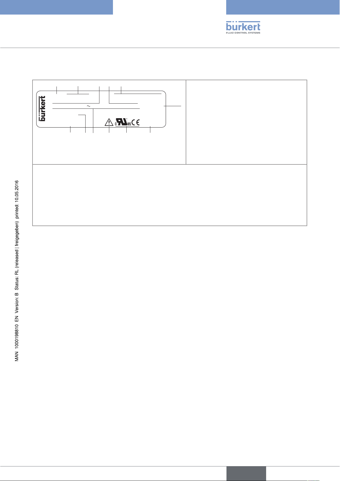
5.4 Description of the name plate
1. Measured value
LFLOW 8025 PANEL SUPPLY: 12-36V= 210 mA
DO1: 5-36V= 100mA AO1:4-20mA
DO2&3: 2xRelay 30 and 42V peak or 60V... max. IP20
S/N 20 000
Made in France
00564417 W46MA
10
9
781112
2. Type of the device, housing
6
3. Specifications of the transistor output DO1
4. Specifications of the analogue output AO1
5. Supply voltage and max. current
consumption
6. Protection class of the device
7. Manufacturing code
8. Conformity logos
9. Warning: Before using the device, take into account the technical specifications described in these operating instructions.
10. Specifications of the relay outputs DO2 and DO3
11. Serial number
12. Order code
Figure 1: Name plate of transmitter 8025 Universal (example)
9
English
Page 12
6 TECHNICAL DATA
6.1 Conditions of use
Ambient temperature -10 to +60 °C
Air humidity < 80 %, non condensated
Height above see level max. 2000 m
Installation class Class I acc. to UL 61010-1
Degree of pollution Degree 2 acc. to EN 61010-1
Protection rating
acc. to EN 60529
Type 8025 UNIVERSAL
Technical data
• wall-mounted version
• panel version
• IP65, device wired, cable glands tightened, cover lid screwed tight and
entry item nuts of the cable glands tightened at a screwing torque of
1.5 Nm.
• front side IP65, rear side IP20
6.2 Conformity to standards and directives
The device conforms to the EC directives through the following standards:
• EMC: EN 61000-6-2, EN 61000-6-3
• LVD: EN 61010-1
• Environnemental testing: Vibration: EN 60068-2-6, Shock: EN 60068-2-27.
The UL devices with PU01 variable key comply with the following standards:
• UL 61010-1
• CAN/CSA-C22.2 n° 61010-1
6.3 General technical data
10
6.3.1 Mechanical data
Part Material
Housing with cover, wall-mounted version ABS
Cable glands, wall-mounted version PA
Open housing, panel version PC
Foil polyester
4 screws Stainless steel
Cable clips PA
English
Page 13
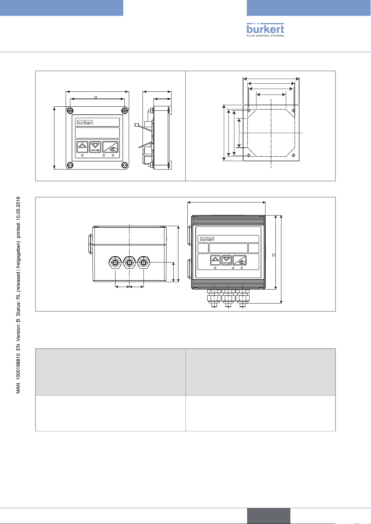
88
95
95
126
Type 8025 UNIVERSAL
Technical data
88
76
FLOW
ENTER
0....9
40
25
80
76
50
Drilling jig
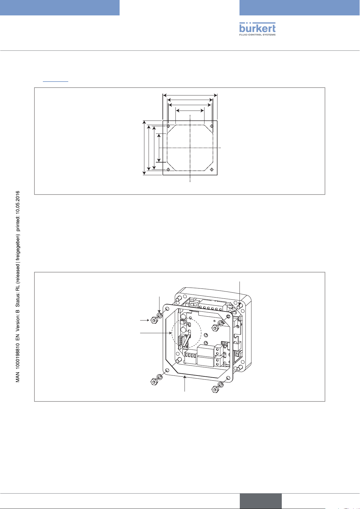
Figure 2: Dimensions of transmitter 8025 Universal, panel version, and of the drilling jig [mm]
80
76
50
FLOW
120
143
23
23
90
31.50
0....9
ENTER
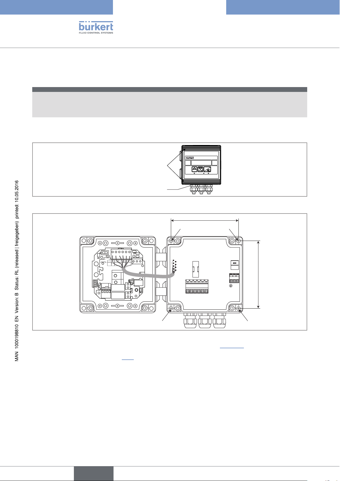
Figure 3: Dimensions of transmitter 8025 Universal, wall-mounted version [mm]
6.3.2 Electrical data
Power supply 12-36 V DC • filtered and regulated
• SELV circuit, with a safe energy level
• max. tolerance 12 V DC: -5 % or +10%
• max. tolerance 36 V DC: ±10 %
Power source (not provided) • Source with limited power in accordance with § 9.3
of the EN 61010-1 standard
• or class 2 source in accordance with the
UL 1310/1585 and EN 60950-1 standards
11
English
Page 14

Power supply 115/230 V AC
Type 8025 UNIVERSAL
Technical data
• frequency
• supplied voltage
• current
• integrated protection
• power
Current consumption (without the consumption of the
4-20 mA output)
• version without relays, energized with 12-36 V DC
• version with relays, energized with 12-36 V DC
• version without relays, energized with 115/230 V AC
• version with relays, energized with 115/230 V AC
Transistor output DO1
• type
• function
• frequency (f)
• Electrical data
• 50/60 Hz
• 27 V DC, regulated
• max. 250 mA
• 250 mA time delay fuse
• 6 VA
• 60 mA (at 12 V DC) and 30 mA (at 36 V DC)
• 90 mA (at 12 V DC) and 45 mA (at 36 V DC)
• 40 mA
• 55 mA
polarized, potential-free
• NPN / PNP (wiring dependent), open collector
• pulse output (by default), user configurable
• 0,6-2200 Hz
• 5-36 V DC, 100 mA max., voltage drop 2,7 V DC at
100 mA
• duty cycle if 0,6 < f < 300 Hz
• duty cycle if 300 < f < 1500 Hz
• duty cycle if 1500 < f < 2200 Hz
• protection
Relay outputs (DO2 and DO3)
• operating
• electrical data of the load (non UL devices)
• electrical data of the load (UL devices)
• max. breaking capacity
• life span
Current output AO1
• specification
• max. loop impedance
• > 0.45
• > 0.4
• < 0.4
• galvanically isolated, and protected against overvoltages, polarity reversals and short-circuits
• hysteresis (by default), user configurable, normally
open
• 230 V AC / 3 A or 40 V DC / 3 A
• max. 30 V AC and 42 V peak or max. 60 V DC, 3 A
• 750 VA (resistive load)
• min. 100000 cycles
• 4-20 mA, sink or source (wiring dependent), 22 mA
to indicate a fault (can be activated)
• 1300W at 36 V DC, 1000W at 30 V DC, 750W at
24 V DC, 300W at 15 V DC, 200W at 12 V DC
12
• 900W if the device is energized with 115/230 V AC
English
Page 15
Type 8025 UNIVERSAL
Technical data
6.3.3 Specifications of the connected flow sensor
Signal originating from the remote sensor
• type
• pulse, sine-wave (typical sensitivity 50 mV peakto-peak at 250 Hz), "on/off", or standard voltage
0-5 V DC
• frequency
• max. voltage
Input impedance
• 0,6 Hz to 2,2 kHz, can be adjusted
• 36 V DC
depends on the position of selector "LOAD" on the
electronic board of the 8025. See chap. “7.4.10”
Power supply supplied by the transmitter depending on the position
of selector "SENSOR SUPPLY" of the 8025, either:
• 5 V DC, 30 mA max.
• (L+)-12V: supply voltage (L+) of the transmitter
minus 12 V DC (minus 12,5 V DC max.), 80 mA max.
• L+: supply voltage (L+) of the transmitter (minus
1,5 V DC max.), 140 mA max. (if the device is energized with 12-36 V DC), 80 mA max. (if the device is
energized with 115/230 V AC)
6.3.4 Electrical connection
Type of connection on the terminal blocks of the electronics (and through
cable glands M16x1,5, for the wall-mounted versions)
Cable specifications
• cable type
• Cross section of wires
• Diameter of each cable (for the cable glands
M16x1,5 of the wall-mounted version)
• shielded
• 0.2 to 1.5 mm
• 4 to 8 mm
2
13
English
Page 16
Type 8025 UNIVERSAL
Installation and wiring
7 INSTALLATION AND WIRING
7.1 Safety instructions
danger
Risk of injury due to electrical voltage.
▶ Shut down the electrical power source of all the conductors and isolate it before carrying out work on the
system.
▶ Observe all applicable accident protection and safety regulations for electrical equipment.
Warning
Risk of injury due to non-conforming installation.
▶ The electrical installation can only be carried out by qualified and skilled staff with the appropriate tools.
▶ Install appropriate safety devices (correctly rated fuse and/or circuit-breaker); For the versions with a
115/230 V AC supply voltage, insert a safety device between the phase and the neutral conductor.
▶ Respect standard NF C 15-100 / IEC 60364.
Risk of injury due to unintentional switch on of power supply or uncontrolled restarting of the
installation.
▶ Take appropriate measures to avoid unintentional activation of the installation.
▶ Guarantee a set or controlled restarting of the process subsequent to any intervention on the device.
Protect this device against electromagnetic interference, ultraviolet rays and, when installed outdoors, the effects of the climatic conditions.
7.2 Installation of a panel version
Install the panel version of the device in a cabinet with a protection class at least IP54 to ensure a
degree of pollution 2 inside the cabinet.
14
English
Page 17
95
95
Type 8025 UNIVERSAL
Installation and wiring
→ To cut the opening in the cabinet door, use the supplied drilling jig, respecting the dimensions indicated in
“Figure 4”.
80
76
50
80
76
50
Drilling jig
Figure 4: Dimensions of the drilling jig [mm]
→ Insert the 4 screws in the housing (from the front).
→ Insert the seal on the external threads of the 4 screws (rear of the housing).
→ Put the assembly on the cutout, electronics turned to the inside of the cabinet.
→ Put the 4 washers on the 4 screws.
→ Put a nut on each of the 4 screws and tighten the nuts to secure the device to the cabinet.
Screws
Washer
Nut
Cable clip
Seal
Figure 5: Installation of a 8025, panel version
15
English
Page 18
11
106 mm
Type 8025 UNIVERSAL
Installation and wiring
7.3 Installation of a wall-mounted version
note
Risk of material damage if the cable glands are not tightly screwed on the housing
▶ Before installing the wall-mounted housing on its support, tighten the nuts of the entry item of the cables
glands at a torque of 1.5 Nm.
The flow transmitter in a wall-mounted version has 4 holes in the bottom of the housing.
→ Remove blanking strips covering the screws.
FLOW
Blanking strips
ENTER
0....9
Nut of the entry item
→ Loosen the 4 screws and open the cover to get access to the holes [1].
SOURCE SINK
CURRENT
BINARY
Iout
L+ L- PE P- P+
Univ
(AO1)
PULSE
Supply
FLOW
SENSOR
Batch
PE
ISOG
DO4
DI4
DI3
DI2
DI1
SUPPLY
INPUT
+-
PULSE
NC
COIL
213PE
NPN/PNP
NC
L+
2.2K
(L+)-12V
12..36Vdc
SENSOR
+5V
470
39K
COIL/PNP
SUPPLY
LOAD
DO1
SENSOR TYPE
COIL NPN/PNP
DO2
DO3
PE PEPE
T 250 mA
OFFON
56789 10
1 1
Figure 6: Installation of a wall-mounted version
→ Secure the housing to the support respecting the dimensions indicated in “Figure 6”.
LN
LN
230V
230V
230V
106 mm
16
→ Wire acc. to instructions in chap. “7.4”.
→ Close the housing and tighten the 4 screws of the cover.
English
Page 19
Type 8025 UNIVERSAL
Installation and wiring
7.4 Wiring
danger
Risk of injury due to electrical voltage.
▶ Shut down the electrical power source of all the conductors and isolate it before carrying out work on the
system.
▶ Observe all applicable accident protection and safety regulations for electrical equipment.
Insert the supplied stopper gaskets into the unused cable glands of a wall-mounted version to ensure the
tightness of the device.
Only move the selectors when the power supply is off.
• Use a filtered and regulated 12-36 V DC power supply.
• Make sure the installation is equipotential. See chap. “7.4.1”.
• Use shielded cables with a temperature limit of 80 °C minimum.
• Do not install the cables near high voltage or high frequency cables; If this cannot be avoided, observe a
min. distance of 30 cm.
• Protect the device power supply by means of a 300 mA fuse and a switch.
• Protect the power supply of each transistor output by means of a 125 mA fuse.
• Protect the relays by means of a max. 3 A fuse and a circuit breaker (depending on the process).
• Do not apply both a dangerous voltage and a safety extra-low voltage to the relays.
7.4.1 Equipotentiality of the installation
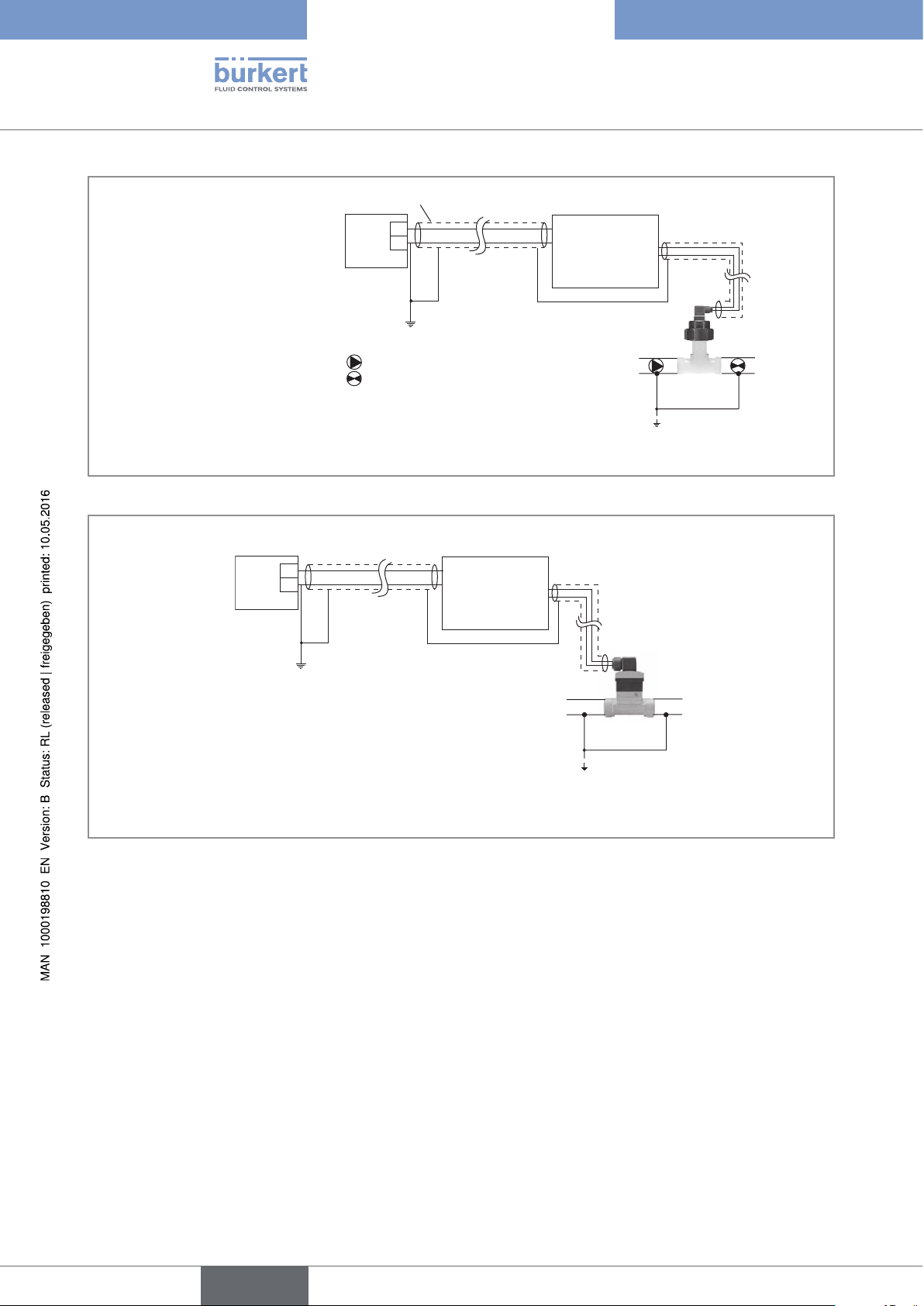
To ensure the equipotentiality of the installation (power supply - device - fluid):
→ Connect together the various earth spots in the installation to eliminate the potential differences that may
occur between different earthes.
→ Observe faultless earthing of the shield of the power supply cable, at both ends.
→ Connect the negative power supply terminal to the earth to suppress the effects of common mode currents. If
this connection cannot be made directly, a 100 nF/50 V capacitor can be fitted between the negative power
supply terminal and the earth.
→ Special attention has to be paid if the device is installed on plastic pipes because there is no direct earthing
possible. Proper earthing is performed by earthing together the metallic instruments such as pumps or valves,
that are as close as possible to the device. If no such instrument is near the device, insert metallic earthing
rings inside the plastic pipes upstream and downstream the device and connect these parts to the same
earth. The earth rings must be in contact with the fluid.
English
17
Page 20
Type 8025 UNIVERSAL
Installation and wiring
Power cable shield
+
-
Power supply
Valve, pump,... (or earth rings, not
provided, inserted into the pipe)
*)
If a direct earth connection is not possible, fit a 100 nF / 50 V capacitor between the negative power supply terminal and
(*)
8025 Universal
Flow sensor
Plastic pipe
the earth.
Figure 7: Equipotentiality skeleton diagram with pipes in plastic
8025 Universal
+
-
Power supply
(*)
Flow sensor
Metal pipe
*)
If a direct earth connection is not possible, fit a 100 nF / 50 V capacitor between the negative power supply terminal and
the earth.
Figure 8: Equipotentiality skeleton diagram with pipes in metal
18
English
Page 21
Type 8025 UNIVERSAL
Installation and wiring
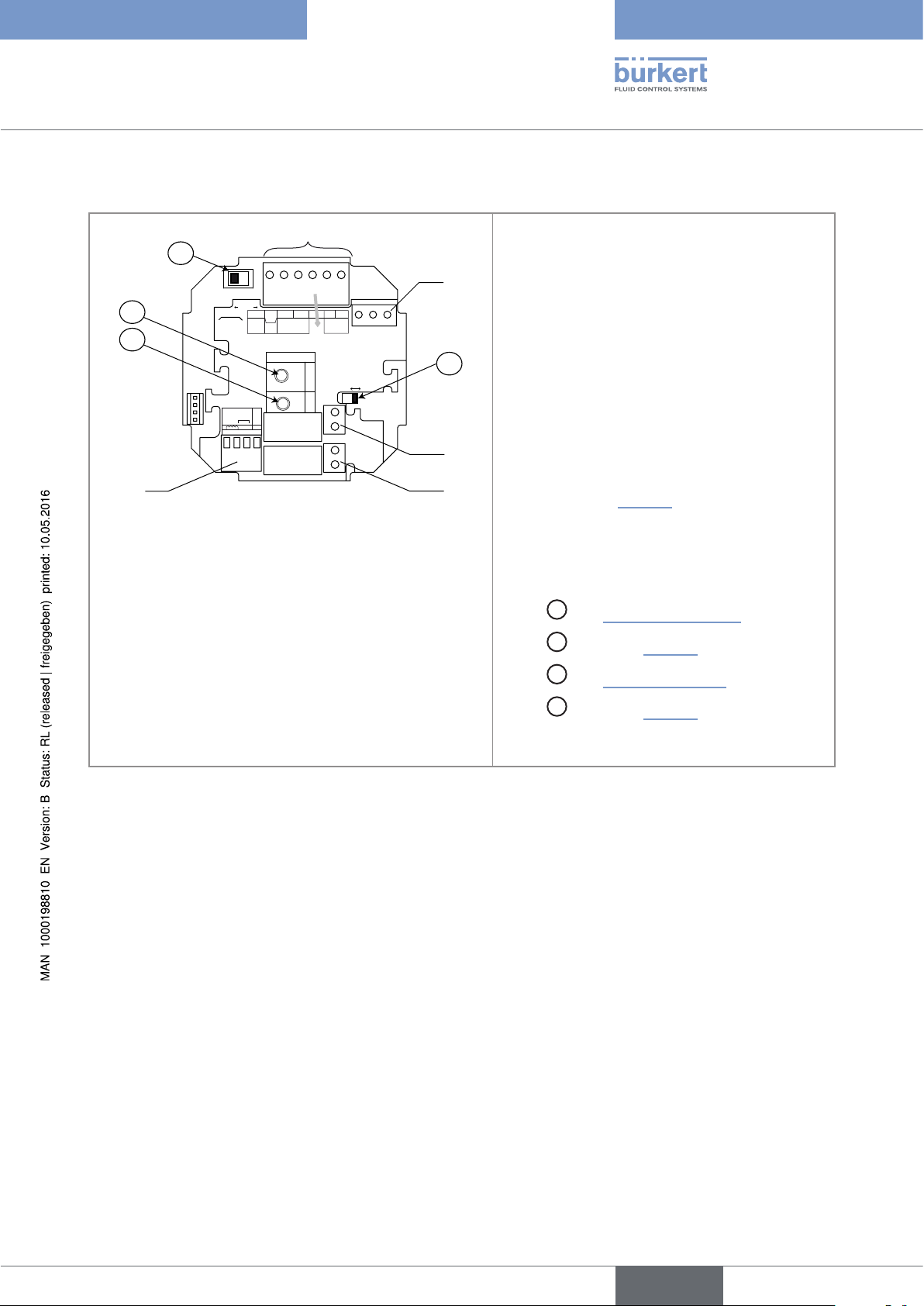
7.4.2 Terminal assignment and use of the selectors
1
A
SOURCESINK
CURRENT
B
BINARY
C
FLOW
SENSOR
PE
ISOG
DO4
DI4
DI3
DI2
DI1
PULSE
INPUT
SUPPLY
+-
NC
213PE
Univ
Batch
COIL
Iout
(AO1)
NC
L+
2.2K
NPN/PNP
L+ L- PE P- P+
Supply
12..36Vdc
SENSOR
+5V
SUPPLY
(L+)-12V
COIL/PNP
470
39K
LOAD
5
Terminal block 1
• Iout: 4-20 mA output (AO1)
• L+: V+ (positive voltage)
• L-: 0V (power supply ground)
• PE: protective earth, factory wired
• P-: Negative transistor output DO1
PULSE
DO1
SENSOR TYPE
COIL NPN/PNP
DO2
DO3
PE PEPE
Terminal block 2
PE: Shieldings of both the power supply cable
2
and the AO1 and DO1 output cables
Terminal block 3 Wiring of the relay output DO2
(if the device has relays).
D
Terminal block 4 Wiring of the relay output DO3
(if the device has relays).
OFF ON
3
4
Terminal block 5 "FLOW SENSOR": Wiring the
remote flow sensor. The wiring depends on the
type of output signal originating from the flow
sensor: see chap. “7.4.10”.
A
Switch
Switch
Switch
Switch
: see “Figure 15”, page 23
B
: see chap. “7.4.10”
C
: see “Table 1”, page 30
D
: see chap. “7.4.10”
• P+: Positive transistor output DO1
Figure 9: Terminal assignment of a panel version or a wall-mounted version, 12-36 V DC
19
English
Page 22
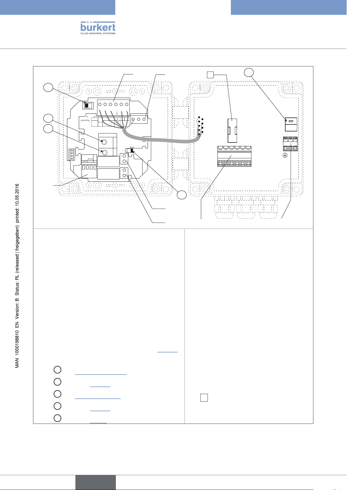
Type 8025 UNIVERSAL
Installation and wiring
2
A
SOURCESINK
CURRENT
BINARY
Iout
L+ L- PE P- P+
FLOW
PULSE
PE
ISOG
DO4
DI4
DI3
DI2
DI1
INPUT
Univ
Batch
SUPPLY
+-
NC
213PE
COIL
(AO1)
NC
L+
2.2K
NPN/PNP
Supply
12..36Vdc
SENSOR
+5V
(L+)-12V
470
39K
SUPPLY
COIL/PNP
LOAD
PULSE
DO1
PE PEPE
SENSOR TYPE
COIL NPN/PNP
DO2
DO3
OFF ON
B
C
SENSOR
3
Terminal block 1
PE: factory wired shield.
Terminal block 2
• Iout: 4-20 mA output (green wire, factory wired)
• L+: V+ (red wire, factory wired)
1
8
E
230V
230V
230V
T 250 mA
LN
LN
56789 10
D
4
5
6 7
Terminal block 4 Wiring of the relay output DO2
(if the device has relays).
Terminal block 5 Wiring of the relay output DO3
(if the device has relays).
Terminal block 6
• terminal 5: 4-20 mA output (AO1)
20
• L-: 0V (black wire, factory wired)
• PE: protective earth, factory wired
• P-: negative transistor output (brown wire, factory wired)
• P+: positive transistor output (white wire, factory wired)
Terminal block 3 "FLOW SENSOR": Wiring the remote
flow sensor. The wiring depends on the type of output
signal originating from the flow sensor: see chap. “7.4.10”.
• terminal 6: positive 27 V DC power supply,
available to energize an external instrument
• terminal 7: 0V (earth of the power supply
available to energize an external instrument)
• terminal 8: protective earth: shields of the AO1
and DO1 output cables
• terminal 9: Negative transistor output (DO1)
• terminal 10: Positive transistor output (DO1)
Switch
A
: see “Figure 15”, page 23
Terminal block 7 Wiring of the 115/230 V AC
power supply
Switch
Switch
Switch
Switch
Figure 10: Terminal assignment of a wall-mounted version, 115/230 V AC
B
: see chap. “7.4.10”
C
: see “Table 1”, page 30
D
: see chap. “7.4.10”
E
: see chap. “7.4.4”
8
Mark
115/230 V AC power supply
: time-delay fuse to protect the
English
Page 23

Type 8025 UNIVERSAL
Installation and wiring
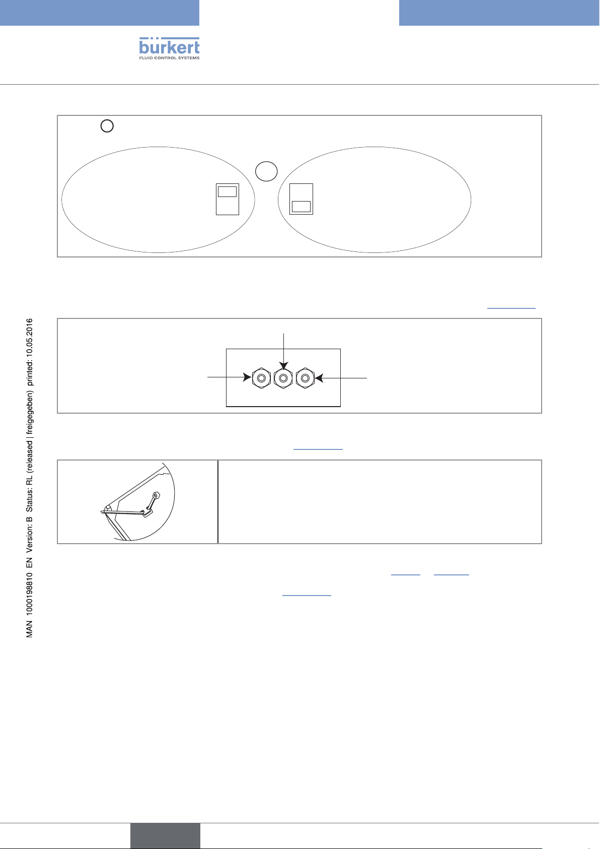
7.4.3 Wiring a panel version
Only move the selectors when the power supply is off.
→ Install the device as described in chap. “7.2”.
→ Set the selectors "SENSOR TYPE", "SENSOR SUPPLY" and "LOAD": see chap. “7.4.10”.
→ Before wiring the device insert the supplied cable clips into the slots of
the electronic board.
Figure 11: Inserting the cable clips
→ Wire acc. to chap. “7.4.5” , “7.4.6”, “7.4.9” and “7.4.10”.
→ Secure the power supply cable, the flow sensor connection cable and, depending on the version, the relay
connection cables, with the cable clips.
7.4.4 Wiring a wall-mounted version
Only move the selectors when the power supply is off.
Insert the supplied stopper gaskets into the unused cable glands to ensure the tightness of the device.
• Unscrew the unused cable gland.
• Remove the transparent disk.
• Insert the supplied stopper gasket.
• Screw the nut of the cable gland.
→ Install the device as described in chap. “7.3”.
→ Set the selectors "SENSOR TYPE", "SENSOR SUPPLY" and "LOAD": see chap. “7.4.10”.
→ If the wall-mounted version is energized with a 115/230 V AC power supply, set selector
“Figure 12”.
E
as shown in
English
21
Page 24
Type 8025 UNIVERSAL
Installation and wiring
E
Selector
makes it possible to configure the supply voltage of the device in a 115/230 V AC version.
E
→ Energize the device with a
230 V AC voltage.
Figure 12: Selector of the supply voltage on a 115/230 V AC version
230V
→ Loosen the nuts of the cable glands.
→ Insert each cable through a nut than through the cable gland, using the cable glands as shown in “Figure 13”.
Cables of the outputs
115V
→ Energize the device with a
115 V AC voltage.
Flow sensor cable
Figure 13: Using the cable glands
Power supply cable
12-36 V DC or 115/230 V AC
→ Remove the two terminal blocks (marked 6 and 7 in “Figure 10”) from the housing.
→ Before wiring the device insert the supplied cable clips into the slots of
the electronic board and of the 115/230 V AC power supply board if
the device has such a board.
Figure 14: Inserting the cable clips
→ Depending on the operating voltage of the device, wire according to chap. “7.4.5” to “7.4.10”.
→ Insert the two terminal blocks (marked 6 and 7 in “Figure 10”) into their original position.
→ Letting the housing stay completely open, secure the power supply cable, the flow sensor connection cable
and, depending on the version, the relay connection cables, with the cable clips.
→ Tighten the cable glands making sure the cable in the housing is long enough to allow complete opening of
the housing.
22
→ Close the cover.
→ Fully screw the 4 screws.
→ Put the blanking strips on the housing.
English
Page 25
12-36 V DC
Type 8025 UNIVERSAL
Installation and wiring
7.4.5 Wiring the AO1 current output of a panel version or a wallmounted version, 12-36 V DC
Only move the selectors when the power supply is off.
Insert the supplied stopper gaskets into the unused cable glands to ensure the tightness of the device.
• Unscrew the unused cable gland.
• Remove the transparent disk.
• Insert the supplied stopper gasket.
• Screw the nut of the cable gland.
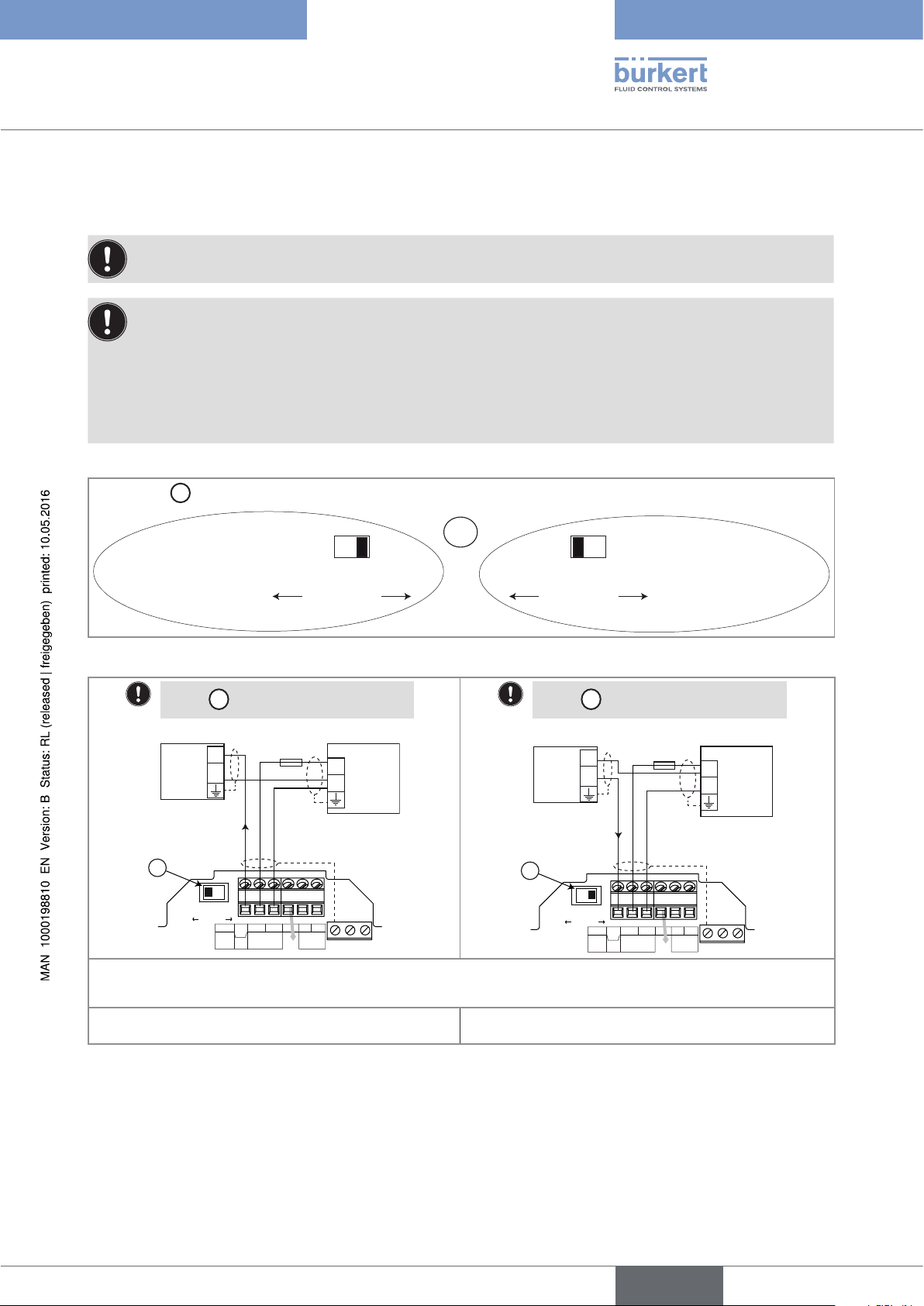
The 4-20 mA output can be wired in either sourcing or sinking mode.
A
Use switch
to configure the wiring of the 4-20 mA current output in sinking or sourcing mode.
A
→ Wire the current
output in sinking
mode.
Figure 15: Using the sink/source switch
Set the A switch on the left.
+
-
4-20mA input at external
*) If a direct earth connection is not possible, fit a 100 nF/50 V capacitor between the negative power supply terminal and
the earth
A
instrument
SOURCESINK
CURRENT
Univ
Batch
SOURCE SINK
CURRENT
12-36 V DC
+
-
(*)
Power supply
PULSE
DO1
PE PEPE
I
Iout
L+ L- PE P- P+
(AO1)
Supply
12..36Vdc
NC
300 mA
SOURCE SINK
CURRENT
Set the A switch on the right.
+
-
4-20mA input at external
A
instrument
SOURCESINK
CURRENT
Univ
Batch
I
Iout
L+ L- PE P- P+
(AO1)
Supply
12..36Vdc
NC
→ Wire the current
output in sourcing
mode.
300 mA
(*)
PULSE
DO1
+
-
Power supply
PE PEPE
Figure 16: Wiring of the 4-20 mA output (AO1) in
sourcing mode
Figure 17: Wiring of the 4-20 mA output (AO1) in sinking
mode
23
English
Page 26
Type 8025 UNIVERSAL
Installation and wiring
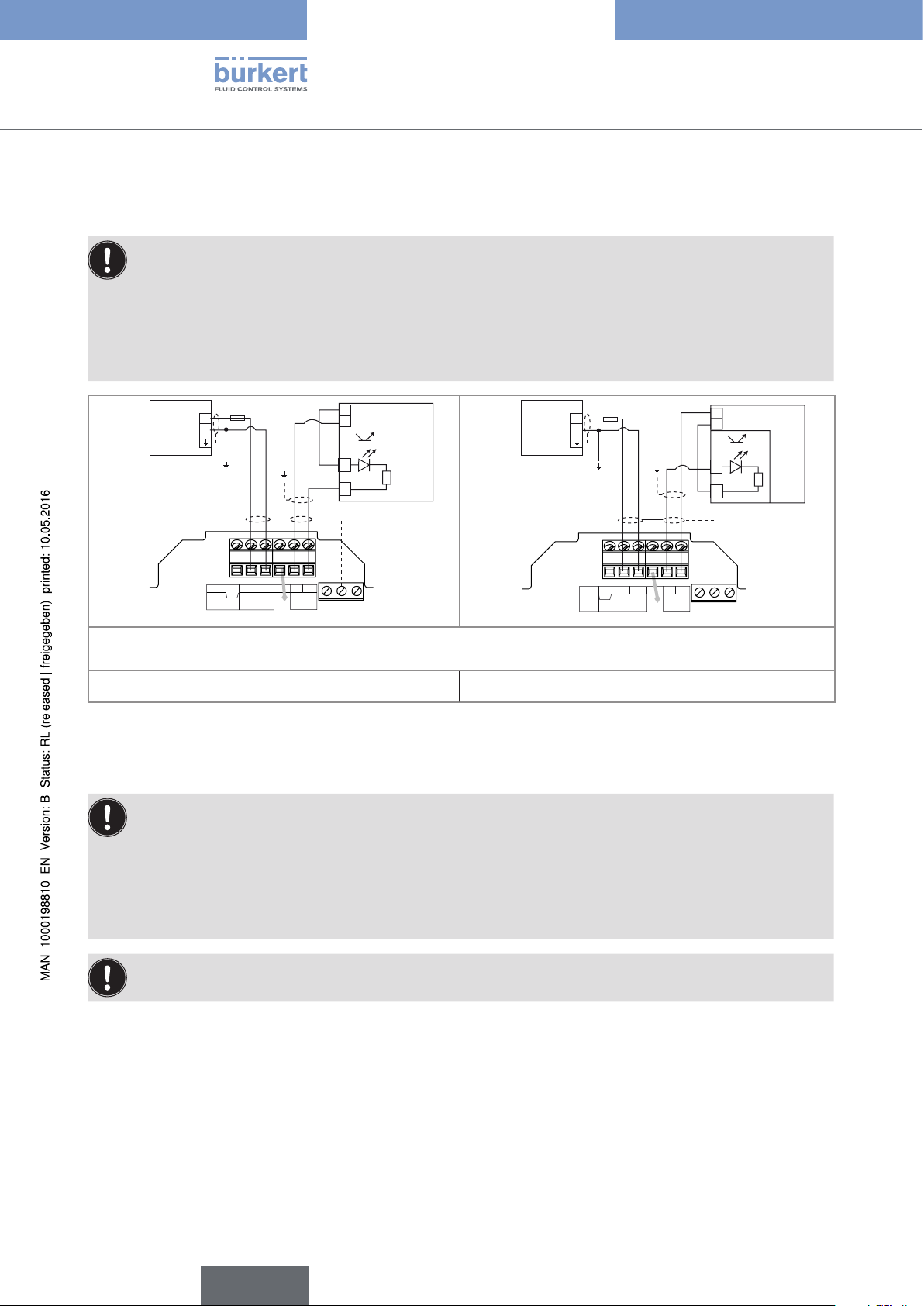
7.4.6 Wiring the DO1 transistor output of a panel version or a wall-mounted version, 12-36 V DC
Insert the supplied stopper gaskets into the unused cable glands to ensure the tightness of the device.
• Unscrew the unused cable gland.
• Remove the transparent disk.
• Insert the supplied stopper gasket.
• Screw the nut of the cable gland.
12-36 V DC
Power supply of
the device
+
-
(*)
Univ
Batch
300 mA
Iout
L+ L- PE P- P+
(AO1)
Supply
12..36Vdc
NC
PULSE
DO1
PE PEPE
+
5-36 VDC
-
+
-
PLC
12-36 V DC
Power supply of
the device
+
-
(*)
Univ
Batch
300 mA
Iout
L+ L- PE P- P+
(AO1)
Supply
12..36Vdc
NC
PULSE
DO1
PE PEPE
+
5-36 VDC
-
+
-
PLC
*) If a direct earth connection is not possible, fit a 100 nF/50 V capacitor between the negative power supply terminal and
the earth
Figure 18: NPN wiring of the DO1 transistor output Figure 19: PNP wiring of the DO1 transistor output
7.4.7 Wiring the AO1 current output of a wall-mounted version, 115/230 V AC
Insert the supplied stopper gaskets into the unused cable glands to ensure the tightness of the device.
• Unscrew the unused cable gland.
24
• Remove the transparent disk.
• Insert the supplied stopper gasket.
• Screw the nut of the cable gland.
Only move the selectors when the power supply is off.
The 4-20 mA output can be wired in either sourcing or sinking mode.
English
Page 27
Type 8025 UNIVERSAL
Installation and wiring
A
• Set the
A
• Set selector
SOURCESINK
CURRENT
BINARY
Univ
Batch
PE
ISOG
DO4
DI4
DI3
DI2
DI1
SUPPLY
INPUT
+-
PULSE
NC
COIL
213PE
FLOW
SENSOR
switch on the left.
E
depending on the value of the power supply.
Iout
L+ L- PE P- P+
(AO1)
NC
L+
2.2K
NPN/PNP
SENSOR
(L+)-12V
Supply
12..36Vdc
+5V
COIL/PNP
470
39K
PULSE
SUPPLY
LOAD
DO1
PE PEPE
SENSOR TYPE
COIL NPN/PNP
DO2
DO3
OFFON
T 250 mA
56789 10
E
230V
230V
230V
LN
LN
Connection of the power
+
-
supply for the 8025
4-20mA input at external instrument
Figure 20: Wiring of the 4-20 mA output (AO1) of a wall-mounted version, 115/230 V AC, in sourcing mode
English
25
Page 28
Type 8025 UNIVERSAL
Installation and wiring
• Set the
• Set selector
A
FLOW
SENSOR
A
switch on the right.
E
depending on the value of the power supply.
SOURCESINK
CURRENT
BINARY
Iout
L+ L- PE P- P+
Univ
(AO1)
Supply
Batch
12..36Vdc
NC
PE
ISOG
DO4
SENSOR
SUPPLY
+-
NC
213PE
+5V
L+
(L+)-12V
COIL/PNP
470
2.2K
39K
NPN/PNP
COIL
PULSE
DI4
DI3
DI2
DI1
INPUT
PULSE
SUPPLY
LOAD
DO1
PE PEPE
SENSOR TYPE
COIL NPN/PNP
DO2
DO3
E
230V
230V
230V
T 250 mA
LN
OFFON
56789 10
LN
Connection of the power
+
-
supply for the 8025
4-20mA input at external instrument
Figure 21: Wiring of the 4-20 mA output (AO1) of a wall-mounted version, 115/230 V AC, in sinking mode
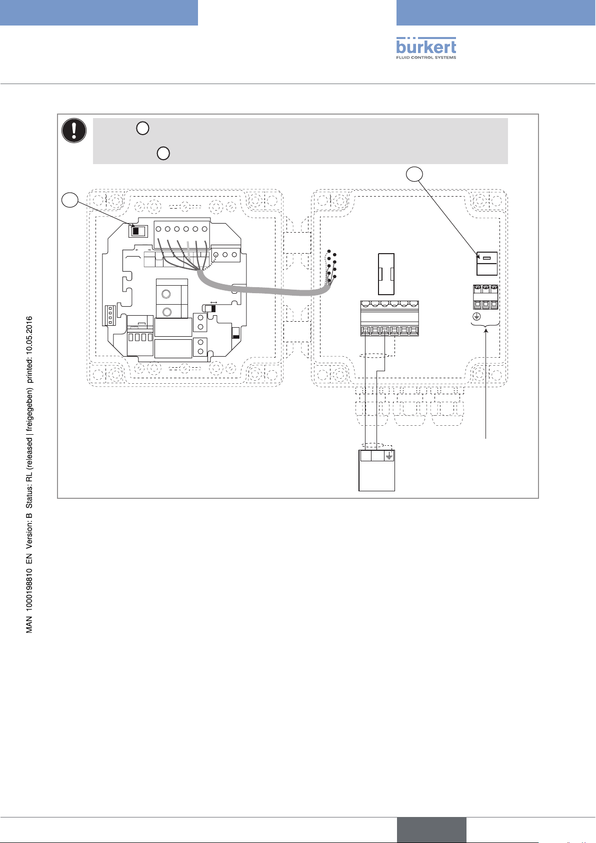
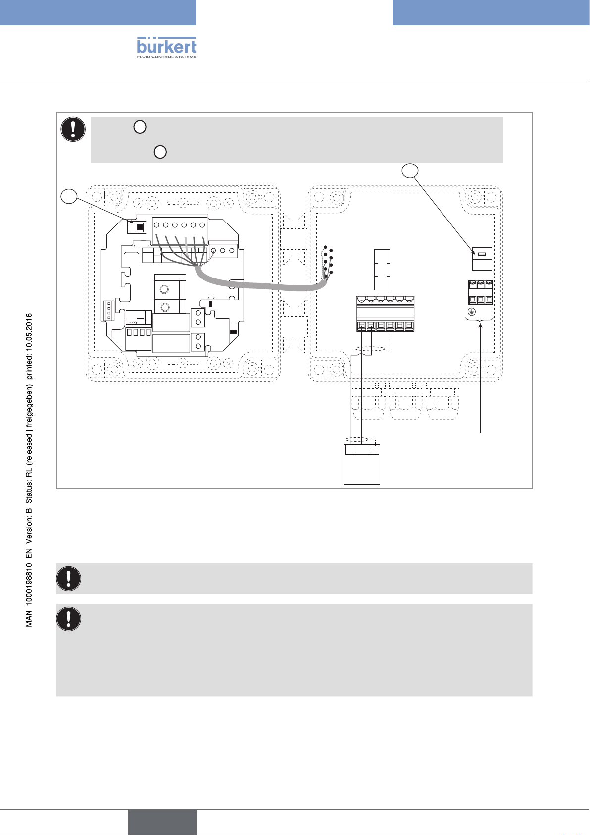
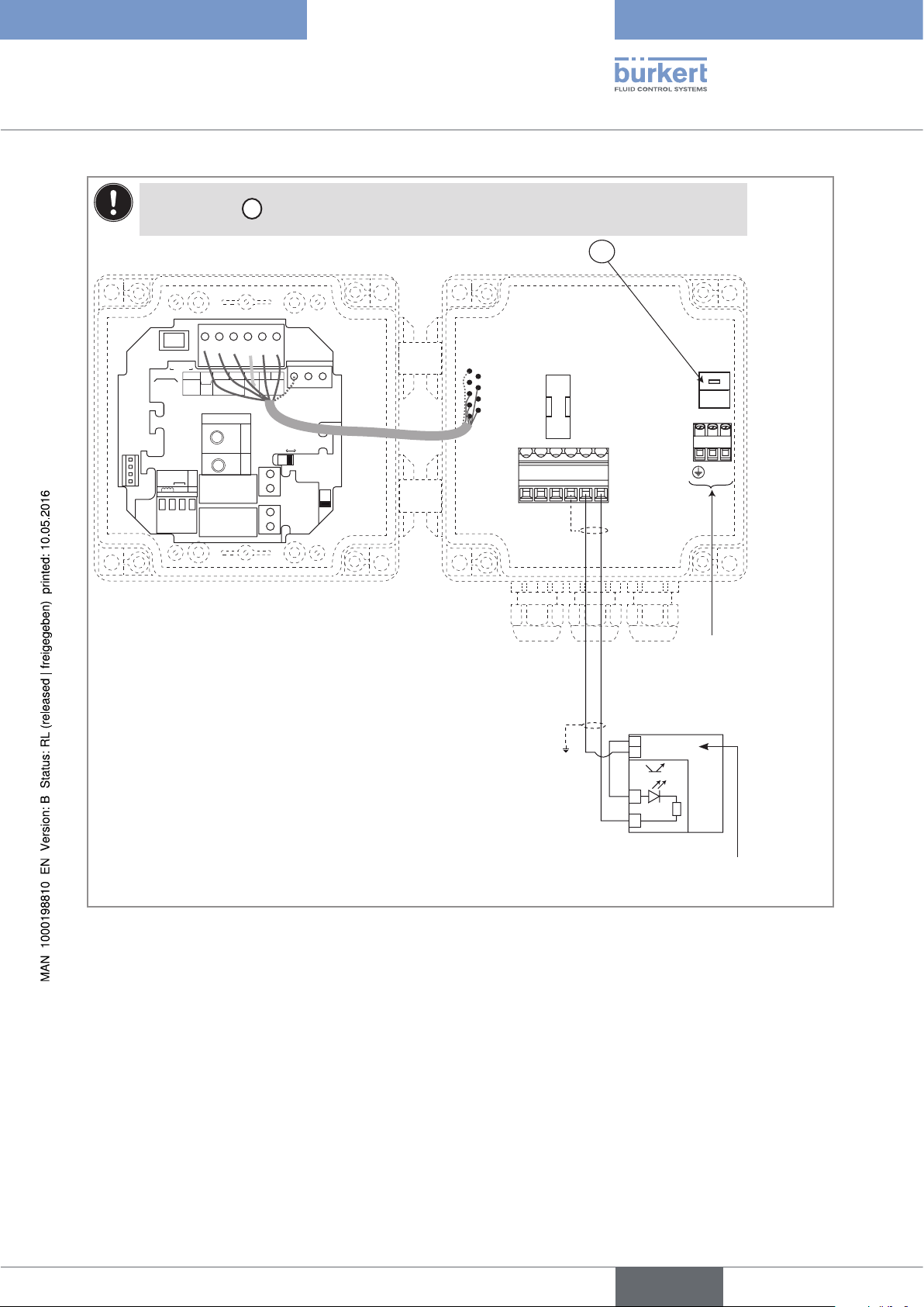
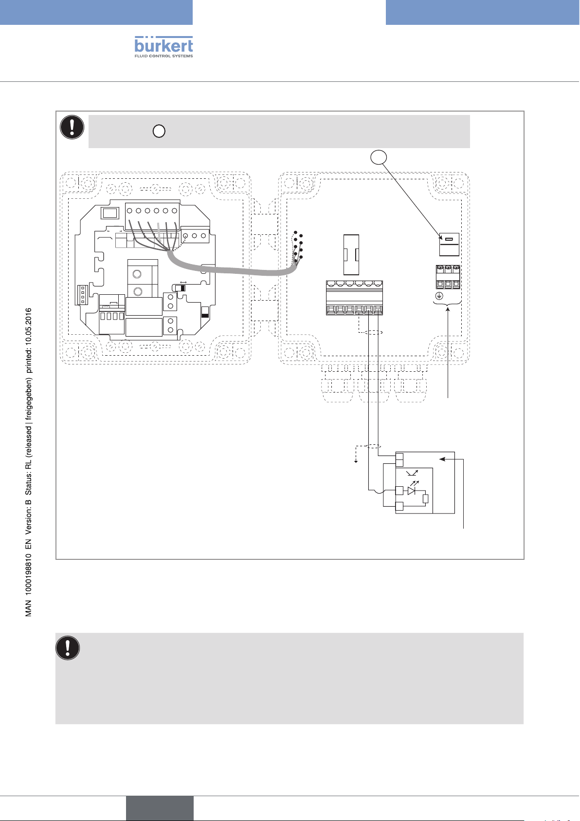
7.4.8 Wiring the DO1 transistor output of a wall-mounted version, 115/230 V AC
Only move the selectors when the power supply is off.
Insert the supplied stopper gaskets into the unused cable glands to ensure the tightness of the device.
• Unscrew the unused cable gland.
• Remove the transparent disk.
• Insert the supplied stopper gasket.
• Screw the nut of the cable gland.
26
English
Page 29
Type 8025 UNIVERSAL
Installation and wiring
Set of selector
SOURCESINK
CURRENT
BINARY
Iout
L+ L- PE P- P+
Univ
(AO1)
Supply
Batch
12..36Vdc
NC
PE
ISOG
DO4
SENSOR
SUPPLY
+-
NC
213PE
+5V
L+
(L+)-12V
470
2.2K
NPN/PNP
COIL
FLOW
SENSOR
PULSE
DI4
DI3
DI2
DI1
INPUT
E
depending on the value of the power supply.
PULSE
DO1
PE PEPE
SENSOR TYPE
SUPPLY
COIL NPN/PNP
COIL/PNP
39K
LOAD
DO2
DO3
OFFON
T 250 mA
56789 10
E
230V
230V
230V
LN
LN
Connection of the power
supply for the 8025
+
5-36 VDC
-
+
-
Figure 22: NPN wiring of the DO1 transistor output of a wall-mounted version, 115/230 V AC
PLC
Power supply for the PLC
English
27
Page 30
Type 8025 UNIVERSAL
Installation and wiring
Set of selector
SOURCESINK
CURRENT
BINARY
Iout
L+ L- PE P- P+
Univ
(AO1)
Supply
Batch
12..36Vdc
NC
PE
ISOG
DO4
SENSOR
SUPPLY
+-
NC
213PE
+5V
L+
(L+)-12V
470
2.2K
NPN/PNP
COIL
FLOW
SENSOR
PULSE
DI4
DI3
DI2
DI1
INPUT
E
depending on the value of the power supply.
PULSE
DO1
PE PEPE
SENSOR TYPE
SUPPLY
COIL NPN/PNP
COIL/PNP
39K
LOAD
DO2
DO3
OFF ON
T 250 mA
56789 10
E
230V
230V
230V
LN
LN
Connection of the power supply
for the 8025
PLC
+
5-36 VDC
-
+
-
Power supply for the PLC
Figure 23: PNP wiring of the DO1 transistor output of a wall-mounted version, 115/230 V AC
7.4.9 Wiring the relay outputs DO2 and DO3 of the panel or a
wall-mounted version
Insert the supplied stopper gaskets into the unused cable glands to ensure the tightness of the device.
• Unscrew the unused cable gland.
• Remove the transparent disk.
• Insert the supplied stopper gasket.
• Screw the nut of the cable gland.
28
English
Page 31

m
SENSOR
Type 8025 UNIVERSAL
Installation and wiring
FLOW
SENSOR
PULSE
INPUT
SUPPLY
+-
NC
213PE
NPN/PNP
COIL
DO2
DO3
OFFON
3 A
3 A
230 V AC
230 V AC
Figure 24: Wiring of the DO2 and DO3 relay outputs
7.4.10 Connecting the flow sensor to the transmitter
Before connecting the flow sensor to the transmitter 8025 UNIVERSAL:
• set selector "SENSOR TYPE" depending on the output signal providing from the flow sensor. See
“Figure 25” and “Table 1”, page 30.
• if the selector "SENSOR TYPE" is set on "NPN/PNP", set the selector "SENSOR SUPPLY" depending
on the transmitter supply voltage. See “Figure 26”.
• set selector "LOAD" depending on the type of signal sent out by the flow sensor and on the load
wanted on terminal 1 "PULSE INPUT" of terminal block "FLOW SENSOR". See “Table 1”, page 30.
D
Selector
makes it possible to configure the type of signal the 8025 Universal receives from the flow sensor.
D
SENSOR TYPE
COIL NPN/PNP
SENSOR TYPE
COIL NPN/PNP
→ Set the selector on the right (default position) when
the signal from the flow sensor which is connected to
the 8025 Universal is either:
• a pulse signal, NPN or PNP
• an "on/off" signal (Reed relay for example)
• a 0-5 V DC standard voltage signal (TTL, for example)
Figure 25: Using selector "SENSOR TYPE"
When selector "SENSOR TYPE"
above is set on "NPN/PNP",
B
selector
makes it possible to
configure the supply voltage for the
flow sensor.
→ If the 8025 Universal is energized with a 115/230 V AC power supply,
set selector "SENSOR SUPPLY" on "L+" (default position).
→ If the 8025 Universal is energized with a 12-36 V DC power supply,
set the voltage selector "SENSOR SUPPLY" depending on the voltage
+5V
B
Figure 26: Using selector "SENSOR SUPPLY"
L+
(L+)-12V
SUPPLY
needed by the remote flow sensor: "+5V", "L+" (default position) or
"(L+)-12V".
→ Set the selector on the left when the
signal from the flow sensor which is
connected to the 8025 Universal is a
sine-wave signal (coil).
29
English
Page 32

13
Type 8025 UNIVERSAL
Installation and wiring
Table 1: Position of selectors "SENSOR TYPE" and "LOAD" and terminal assignment of terminal block "FLOW
SENSOR" depending on the signal emitted by the flow sensor
Terminal assignment of
Type of signal
emitted by the
flow sensor
Selector
"SENSOR
TYPE"
D
)
(
Selector
"SENSOR
SUPPLY"
(B)
Selector "LOAD"
C
2.2K
470
COIL/PNP
39K
terminal block "FLOW
SENSOR"
LOAD
FLOW
SENSOR
8025
PULSE
INPUT
SUPPLY
2
+-
NPN/PNP
NC
COIL
PE
sinusoid (coil)
pulse, PNP
→ Set the
selector
on "COIL"
(“Figure
25”)
→ Set the
selector on
"NPN/PNP"
(“Figure
25”)
→ Any
position.
→ Set the
selector as
shown in
“Figure 26”.
→ Set selector "LOAD" on
"39K": the input impedance
on terminals 1 and 2 of
terminal block "FLOW
SENSOR" will then be
39 kW
→ Set selector "LOAD" on
"39K": the input impedance
on terminals 1 and 2 of
terminal block "FLOW
SENSOR" will then be
39 kW
39 kΩ
NC
213PE
Flow sensor
8025
39 kΩ
213PE
30
Flow sensor
English
Page 33

13
Type 8025 UNIVERSAL
Installation and wiring
Type of signal
emitted by the
flow sensor
Selector
"SENSOR
TYPE"
(
Terminal assignment of
Selector
"SENSOR
SUPPLY"
D
)
(B)
C
470
2.2K
COIL/PNP
39K
Selector "LOAD"
terminal block "FLOW
SENSOR"
LOAD
FLOW
SENSOR
39 kΩ
SUPPLY
INPUT
PULSE
2
8025
213PE
+-
NPN/PNP
NC
COIL
PE
0-5 V DC
standard
voltage signal
(TTL, for
example)
pulse, NPN
→ Set the
selector on
"NPN/PNP"
(“Figure
25”)
→ Set the
selector on
"NPN/PNP"
(“Figure
25”)
→ Set the
selector as
shown in
“Figure 26”.
→ Set the
selector as
shown in
“Figure 26”.
→ Set selector "LOAD" on
"39K": the input impedance
on terminals 1 and 2 of
terminal block "FLOW
SENSOR" will then be
39 kW
Flow sensor
8025
+3 V
R
213PE
→ Set selector "LOAD":
• either on "2.2k": the load
resistance R is then 2,2 kW
• either on "470": the load
resistance R is then 470 W
Flow sensor
31
English
Page 34

Type of signal
13
emitted by the
flow sensor
"on/off" signal
(Reed relay for
example)
Selector
"SENSOR
TYPE"
D
)
(
→ Set the
selector on
"NPN/PNP"
(“Figure
25”)
Selector
"SENSOR
SUPPLY"
(B)
→ Set the
selector as
shown in
“Figure 26”.
Selector "LOAD"
COIL/PNP
470
C
2.2K
39K
→ Set selector "LOAD":
• either on "2.2k": the load
resistance R is then 2,2 kW
• either on "470": the load
resistance R is then 470 W
Type 8025 UNIVERSAL
Installation and wiring
Terminal assignment of
terminal block "FLOW
SENSOR"
SUPPLY
INPUT
+-
NPN/PNP
PULSE
NC
COIL
2
LOAD
FLOW
SENSOR
8025
R
PE
+3 V
213PE
Table 2: Default positions of selectors "SENSOR SUPPLY", "LOAD" and "SENSOR TYPE"
Selector Default position
SENSOR SUPPLY (
LOAD (
SENSOR TYPE (
C
)
D
B
)
)
L+
2.2KOhms
NPN/PNP
...
Flow sensor
32
English
Page 35

Type 8025 UNIVERSAL
Operating and commissioning
8 OPERATING AND COMMISSIONING
8.1 Safety instructions
Warning
Risk of injury due to nonconforming operating.
Nonconforming operating could lead to injuries and damage the device and its surroundings.
▶ The operators in charge of operating must have read and understood the contents of this manual.
▶ In particular, observe the safety recommendations and intended use.
▶ The device/installation must only be operated by suitably trained staff.
Warning
Danger due to nonconforming commissioning.
Nonconforming commissioning could lead to injuries and damage the device and its surroundings.
▶ Before commissioning, make sure that the staff in charge have read and fully understood the contents of the
operating instructions.
▶ In particular, observe the safety recommendations and intended use.
▶ The device / the installation must only be commissioned by suitably trained staff.
▶ Before commissioning the device, enter the K factor of the fitting used. See chap. “8.6.3”.
8.2 Operating levels of the device
The device has two operating levels: the Process level and the Configuration level.
The Process level makes it possible:
• to read the flow rate measured by the device, the value of the current transmitted on the 4-20 mA analogue
output, the values of both the daily and main totalizers.
• to reset the daily totalizer.
• to access the Configuration level.
The Configuration level comprises three menus (Parameters, Test and Information) and makes it possible:
• to set the device parameters.
• to test some device parameters.
• to read, when the status LED of the device is orange or red, the warning and fault messages generated by the
device.
Table 3: Default settings of the device
Function Default value
LANGUAGE English
UNIT of the flow rate l/min
UNIT of the totalizers litre
English
33
Page 36

Function Default value
OUTPUT AO1 4mA= 0.000
20mA= 0.000
ERR. 22mA disabled
OUTPUT DO1 pulse
PU= 0.00 litre
OUTPUTS DO2 and DO3 Hysteresis, not inverted
2- = 3- = 0.000
2+ = 3+ = 0.000
time delays 2 and 3 = 0
K FACTOR
FILTER
CUT-OFF
1
2, fast
0.000
BACKLIT level 9, activated for 30s
FLOW-WARNING W- = W+ = 0.000
VOLUME-WARNING 000000
Type 8025 UNIVERSAL
Operating and commissioning
Process level
12.6 L/MiN
16.45 MA
0......9
87654 L
231 L.
+
0......9
> 2 s
To reset the daily totalizer
(identified by a dot after the
volume units).
> 5 s
Parameters menu
ENTER
0......9
> 5 s
0......9
LANGUAGE
UNit
K-FACtOR
OUtPUt
FiLtER
tOtAL
CUt-OFF
Configuration level
ENTER
0......9
> 2 s
Test Menu
CAL AO1
FREQUENC.
FLOw
wARNiNG
END
Information menu
MEAS. OVF
DiSP. OVF
AO1 LOSt
0......9
END
ENTER
1)
34
BACKLit
END
1)
Accessible when the device status LED is orange or red (see chap. “8.3”).
English
SAVE N/Y
Process
level
Page 37

Type 8025 UNIVERSAL
Operating and commissioning
8.3 Description of the navigation keys and the status
LEDs
• Scrolling up the
parameters
• Incrementing the figure
selected
Device status LED: see
following table.
Device status
LED
Green The device operates correctly.
Orange
Status of the device
A warning message is generated.
• Selecting the displayed
parameter
• Confirming the settings
Status LED of relay DO3 (LED ON
= contact closed)
Status LED of relay DO2 (LED ON
= contact closed)
• Reading the messages
• Scrolling through the parameters
• Selecting the figure on the left
Red
Blinking,
whatever the
colour
→ Press the key for 2 seconds in the Process level to access the message. See
chap. “9.3” for the meaning of the message.
Furthermore, a relay output (DO2 or DO3) or the transistor output DO1 switches if it is
configured in the "WARNING" mode (see Figure 41 or Figure 43)
An error message has been generated and the current output sends out a 22 mA current (if
parameter "ERR. 22mA" is set to "ENABLED". See chap. “8.6.7”. ) .
→ Press the key for 2 seconds in the Process level to access the message. See
chap. “9.3” for the meaning of the message.
A check for the correct behaviour of the outputs is running (see chap. “8.7.3”)
35
English
Page 38

8.4 Using the navigation keys
You want to... Press...
move between parameters within a level or a menu.
access the Parameters menu.
•
to go to the next parameter.
•
to go to the previous parameter.
0......9
ENTER
+ simultaneously for 5 s, in the Process level
Type 8025 UNIVERSAL
Operating and commissioning
access the Test menu.
access the Information menu.
reset the daily totalizer, from the Process level.
select the displayed parameter.
confirm the displayed value.
modify a numerical value.
0......9
+ +
ENTER
simultaneously for 5 s, in the Process
level
for 2 s, in the Process level, when the device status
LED is orange or red.
0......9
+ simultaneously for 2 s, when the daily totalizer
is displayed in the Process level
ENTER
ENTER
•
to increase the blinking digit.
0......9
to select the digit at the left of the blinking digit.
•
0......9
+ to move the decimal point.
•
36
English
Page 39

Type 8025 UNIVERSAL
Operating and commissioning
8.5 Details of the Process level
This level is active by default when the device is energized.
The displayed flow rate is set to 0 (a dot is displayed after the
flow rate units when the funntion CUT-OFF is active) because
0......9
12.6 L/MiN
16.45 MA
or
0 L/MiN.
Value of the measured flow rate, displayed in the unit chosen in the "UNIT" parameter
of the Parameters menu.
Value of the current output, proportional to the measured flow rate.
the measured flow rate is below the threshold value defined in
the "CUT-OFF" parameter of the Parameters menu. See chap.
“8.6.16”.
87654 L
Value of the main totalizer, volume of fluid counted by the device since the last reset.
Value of the daily totalizer (identified by a dot after the volume units), volume of fluid
231 L.
counted by the device since the last reset.
0......9
+
> 2 s
Resetting the daily totalizer.
8.6 Details of the Parameters menu
ENTER
To access the Parameters menu, simultaneously press keys
This menu comprises the following configurable parameters:
for at least 5 s.
English
37
Page 40

Type 8025 UNIVERSAL
Operating and commissioning
0......9
LANGUAGE
UNit
K-FACtOR
OUtPUt
FiLtER
tOtAL
CUt-OFF
BACKLit
END
Choosing the display language
Choosing the flow rate unit, the number of decimals and the unit the totalizers are
displayed in.
Entering the K factor of the fitting used or have it defined through a Teach-In
procedure.
Parameterizing the 4-20 mA current output (AO1) and configuring the transistor
output (DO1) and, if the device is equipped with, the 2 relay outputs (DO2 and DO3).
Choosing the filter level of the measured flow rate, on the displayed flow rate and the
AO1 current output.
Resetting both totalizers.
Entering the measured flow rate value below which the device sets the measured flow
rate to 0 with effect on the display, the outputs and the totalizers.
Setting the brightness of the display and how long it stays ON, or deactivating the
backlight.
SAVE N/Y
Saving the changes made within the Parameters
menu or not. If the changes are saved, the device
operates with the new settings.
12.6 L/MiN
Process level
Figure 27: Diagram of the Parameters menu
8.6.1 Choosing the display language
When the device is energized for the first time, the display language is English.
LANGUAGE ENGLiSh
DEUtSCh
0......9
FRANçAiS
→ Confirm the displayed language: the
selected language is immediately active.
itALiANO
ESPANOL
UNit
Figure 28: Diagram of the "LANGUAGE" parameter of the Parameters menu
→ If you do not want to adjust another parameter, go to the "END" parameter of the Parameters menu and press
ENTER
to save the settings or not and go back to the Process level.
38
English
Page 41

Type 8025 UNIVERSAL
Operating and commissioning
8.6.2 Choosing the flow rate units, the number of decimals and the units of the totalizers
When the flow rate unit has been changed:
• Manually reset both totalizers.
• Manually convert the flow rate values in the different settings.
• If, furthermore, the unit changes from "metric" to "gallon" and vice versa, convert the K factor using following formulae:
- K factor in pulse/US Gallon = K factor in pulse/l x 3,785
- K factor in pulse/IMP Gallon = K factor in pulse/l x 4,546
The max. flow rate that can be displayed depends on the number of decimals chosen:
• 9999 if the number of decimals = 0 or AUTO,
• 999,9 if the number of decimals = 1,
• 99,99 if the number of decimals = 2,
• 9,999 if the number of decimals = 3.
• If the units chosen for the totalizers is "millilitre", the totalizer values are displayed in litres followed by
three decimals.
• If the units chosen for the totalizers is "litre", the totalizer values are displayed in litres without decimals.
The "UNIT" parameter makes it possible to choose:
• the flow rate units.
• a fixed number of decimals (choose 0, 1, 2 or 3) to display the flow rate in the Process level, or a floating
decimal point (choose "AUTO"): the device automatically adjusts the position of the decimal point depending
on the chosen unit and the measured flow rate.
• the volume units of the totalizers if the unit previously chosen is in litres, in millilitres or in m
3
. The totalizer values
are automatically displayed in gallons if the flow rate unit chosen is in gallons.
English
39
Page 42

Type 8025 UNIVERSAL
Operating and commissioning
UNit MLit/SEC
FLOw
MLit/MiN
MLit/h
Lit/SEC
Lit/MiN
Lit/h
M3/MiN
0......9
M3/h
US GAL/S
0......9
US GAL/M
US GAL/h
iMP GA/S
→ Choose the flow rate
unit.
→ Confirm
AUtO
DEC Pt 3
0......9
DEC Pt 2
DEC Pt 1
DEC Pt 0
→ Choose the
number of decimal
positions.
→ Confirm
iMP GA/M
GA/h
If the chosen unit is in litres, millilitres or m3.
tOtAL
0......9
MLitRE
LitRE
→ Choose the totalizer unit.
→ Confirm
If the chosen
unit is in
gallons.
M3
K-FACtOR
Figure 29: Diagram of the "UNIT" parameter of the Parameters menu
→ If you do not want to adjust another parameter, go to the "END" parameter of the Parameters menu and press
ENTER
to save the settings or not and go back to the Process level.
REtURN
40
English
Page 43

Type 8025 UNIVERSAL
Operating and commissioning
8.6.3 Entering the K factor of the fitting used
The device determines the flow rate in the pipe using the fitting K factor.
The K factor of the fitting used can be entered here. The device may also determine the K factor using a Teach-In
procedure: see chap. “8.6.4”.
The device will use the new K factor as soon as "SAVE YES" is confirmed when leaving the Parameters
menu.
The K factor of the fitting used is in the operating instructions of the fitting.
The operating instructions of the Bürkert fittings can be found on the CD delivered with the device or on
the internet at www.burkert.com.
K-FACtOR K=10.000
The display shows the K factor of
the fitting, last entered or determined
using a Teach-In procedure.
K=2.8500
→ Enter the K factor (value between 0.01 and
99999.9) of the fitting used.
→ Confirm the displayed value.
→ Edit the parameter.
OUtPUt VALiD N/Y
REtURN
Is only displayed if the K factor has been changed.
→ Confirm the entered K factor or not.
Figure 30: Entering the K factor of the fitting used
→ If you do not want to adjust another parameter, go to the "END" parameter of the Parameters menu and press
ENTER
to save the settings or not and go back to the Process level.
8.6.4 Determining the fitting K factor using a Teach-In procedure
The device determines the flow rate in the pipe using the fitting K factor.
The "TEACH V." or "TEACH F." parameter allows the device to determine the fitting K factor using a Teach-In
procedure. The K factor may also be directly entered: see chap. “8.6.3”.
The Teach-In can be done either depending on a known volume ("TEACH V.") or depending on the flow rate
("TEACH F.") in the pipe, measured by a reference instrument.
English
41
Page 44

Type 8025 UNIVERSAL
Operating and commissioning
Determining the fitting K factor using a Teach-In procedure depending on a volume ("TEACH V.")
The device will use the new K factor as soon as "SAVE YES" is confirmed when leaving the Parameters
menu.
→ Prepare a tank with a known volume.
→ Stop the fluid circulation.
→ Confirm "TEACH V.": "FILL END" is displayed.
K-FACtOR K=2.8500
tEACh V.
0......9
tEACh F.
The display shows the K factor of the fitting, may it have been entered
or determined by a Teach-In procedure.
FiLL END
→ Charge the pipe to fill the tank.
→ When the tank is full, confirm "FILL END":
0000.0 L
→ Enter the volume (value between 0.1 and 9999.9 in the units
chosen for the totalizers at the "UNIT" parameter) of fluid
that passed in the circuit.
→ Confirm.
K=2.9000
The device calculates the K factor of the fitting
and displays it.
→ Confirm the displayed value.
42
OUtPUt
REtURN
VALiD N/Y
→ Confirm the K factor determined through Teach-In or not.
Figure 31: Teach-In procedure depending on a volume
→ If you do not want to adjust another parameter, go to the "END" parameter of the Parameters menu and press
ENTER
to save the settings or not and go back to the Process level.
English
Page 45

Type 8025 UNIVERSAL
Operating and commissioning
Determine the fitting K factor using a Teach-In procedure depending on a volume ("TEACH F.")
The device will use the new K factor as soon as "SAVE YES" is confirmed when leaving the Parameters
menu.
→ Charge the pipe.
→ Wait for the flow rate to be stable.
→ confirm "TEACH F.": "MEASURE \" is displayed.
K-FACtOR K=10.000
tEACh V.
tEACh F.
0......9
The display shows the K factor of the fitting, may it have been entered
or determined by a Teach-In procedure.
MEASURE \
The device calculates the mean flow rate in the pipe, during
approximately 50 s.
0.000 L/MiN
→ Enter the actual flow rate (value between 0.001 and
9999, in the units chosen for the flow rate at the "UNIT"
parameter) in the pipe, which has been measured by a
reference instrument.
→ Confirm.
The device calculates the K factor of the fitting and displays
it.
K=2.8500
→ Confirm the displayed value.
OUtPUt
REtURN
VALiD N/Y
→ Confirm the K factor determined through Teach-In or
not.
Figure 32: Teach-In procedure depending on the flow rate
→ If you do not want to adjust another parameter, go to the "END" parameter of the Parameters menu and press
ENTER
to save the settings or not and go back to the Process level.
English
43
Page 46

Type 8025 UNIVERSAL
Operating and commissioning
8.6.5 Configuring the outputs (general diagram)
OUtPUt AO1
DO1 PULSE
0......9
0......9
0......9
4MA-20MA
ERR. 22MA.
REtURN
hYStERES.
wiNDOw
wARNiNG
Parameterizing the 4-20 mA analogue output, AO1. See chap.
“8.6.6”.
Activate / deactivate the generation of a 22 mA current on the
AO1 current output, when the device generates a fault. See
chap. “8.6.7”.
Configuring the transistor output DO1 as a pulse output. See
“Figure 36”, chap. “8.6.8”.
Configuring the transistor output DO1 to switch a load
depending on two threshold values. See “Figure 39” and
“Figure 38”, chap. “8.6.8”.
Configuring the transistor output DO1 to switch a load when a
warning message is generated by the device. See “Figure 41”
chap. “8.6.8”.
If the device is equipped with relays, configuring the relay
DO2
hYStERES.
output DO2 or DO3 to switch a load depending on two
threshold values. See “Figure 39”, chap. “8.6.8” and “Figure
DO3
wiNDOw
0......9
42” chap. “8.6.12”.
If the device is equipped with relays, configuring the relay
wARNiNG
output DO2 or DO3 to switch a load when a warning message
is emitted by the device. See “Figure 43” chap. “8.6.12”.
FiLtER
Figure 33: Diagram of the "OUTPUT" parameter of the Parameters menu
REtURN
8.6.6 Associating a flow rate range to the current output AO1
The 4-20 mA output provides an electrical current, the value of which reflects the flow rate measured by the
device.
Example of relation between the measuring range and the current output:
mA
20
44
English
4
20 180
l/min
Page 47

Type 8025 UNIVERSAL
Operating and commissioning
OUtPUt 4 = 20.00AO1
4MA-20MA
→ Enter the flow rate associated to a 4 mA current
value, in the unit chosen in the "UNIT" parameter.
→ Confirm.
ERR. 22MA.
See chap. 8.6.7.
20 = 180.0
→ Enter the flow rate associated to a 20 mA current
value, in the unit chosen in the "UNIT" parameter.
→ Confirm.
→ To invert the output signal, give a lower flow rate value to the 20 mA current value than to the 4 mA current
value.
→ To disable the current output, set both range bounds, 4 and 20 mA, to zero. In this case the output delivers a
constant current of 4 mA.
Figure 34: Associating a flow rate range to the current output
8.6.7 Activating / Deactivating the emission of a 22 mA current
on the current output
When the device generates an operating fault (see chap. “9.3.2”), the current output can be configured to send
out a 22 mA current even if the current output is deactivated.
OUtPUt ERR. 22MA.AO1
ENABLE
→ Activate / deactivate the generation of
0......9
DiSABLE
a 22 mA current on the current output,
when the device generates a fault.
→ Confirm.
DO1
Figure 35: Activating or deactivating the emission of a 22 mA current
→ If you do not want to adjust another parameter, go to the "END" parameter of the Parameters menu and press
ENTER
to save the settings or not and go back to the Process level.
English
45
Page 48

Type 8025 UNIVERSAL
Operating and commissioning
8.6.8 Configuring the transistor output DO1 as a pulse output
proportional to a volume
When the DO1 transistor output is configured as a pulse output, a pulse is transmitted on the output each time
the parametered volume of fluid has been measured by the device.
• When the frequency emitted on the pulse output is between 0,6 and 300 Hz, the duty cycle of the
signal is between 45% and 60%.
• When the frequency emitted on the pulse output is between 300 and 1500 Hz, the duty cycle of the
signal is between 40% and 50%.
• When the frequency emitted on the pulse output is between 1500 and 2200 Hz, detection on a pulse
edge is possible.
OUtPUt DO1 PULSE
LitRE
→ Choose the volume unit of a pulse. The available volume
units depend on the chosen flow rate unit. See chap.
“8.6.2”.
→ Confirm.
DO2 PU=01.000
See chap. 8.6.12 et 8.6.13.
→ Enter the volume of fluid (value between 0.000 and 9999.9) for which a
pulse is transmitted on the transistor output.
→ To deactivate the pulse output, set PU to zero: the output is always open
and no pulse is transmitted.
→ Confirm.
→ If the message "PU H LIM" or "PU L LIM" is displayed, see chap. “9.3.6”.
Figure 36: Configuration of the transistor output DO1 as a pulse output propotional to a volume
8.6.9 Configuring the transistor output DO1 to transmit the rotational frequency of the paddle wheel
46
When the transistor output DO1 is configured in "PULSE" mode and the unit "HERTZ" is chosen, each pulse
from the paddle wheel flow sensor is transmitted to the transistor output DO1. The frequency generated by this
output then equals the rotational frequency of the paddle wheel (this value can be read from the parameter "FREQUENC" in the Test menu).
→ Choose "HERTZ".
OUtPUt DO1 PULSE
hERtz
→ Confirm.
DO2
See chap. 8.6.12 et 8.6.13.
Figure 37: Configuration of the transistor output DO1 as a pulse output propotional to the rotational frequency of the
paddle wheel
English
Page 49

Type 8025 UNIVERSAL
Operating and commissioning
8.6.10 Configuring the transistor output DO1 to switch a load depending on two threshold values
OUtPUt DO1 hYStERES.
wiNDOw
1-= 0.000
→ Enter a flow rate value
threshold, in the unit chosen in the "UNIT" parameter.
1)
, associated to the low
→ Confirm.
1+= 0.000
→ Enter a flow rate value
threshold, in the unit chosen in the "UNIT" parameter.
1)
, associated to the high
→ Confirm.
iNV YES
0......9
iNV NO
→ Choose the operating, inverted or not inverted, of the
transistor output.
DO2
On a version WITH relay outputs
(see chap. 8.6.12 et 8.6.13.
DEL. 1= 00
→ Enter the delay before switching (value between 0
and 99 s).
→ Confirm.
FiLtER
1)
If hysteresis operating: value set for 1- ≤ value set for 1+.
If window operating: value set for 1- < value set for 1+.
Figure 38: Configuration of the DO1 transistor output with switching thresholds
→ If you do not want to adjust another parameter, go to the "END" parameter of the Parameters menu and press
ENTER
to save the settings or not and go back to the Process level.
REtURN
On a version WITHOUT
relay outputs
47
English
Page 50

O
O
O
Type 8025 UNIVERSAL
Operating and commissioning
Hysteresis operating
The output status changes when a threshold is reached:
• by increasing flow rate, the output status changes when the high threshold X+ is reached.
• by decreasing flow rate, the output status changes when the low threshold X- is reached.
Contact
ON
OFF
Not inverted
X- X+
flow rate
Contact
ON
FF
Inverted
flow rate
X- X+
X- = low switching threshold of the transistor or the relay (1-, 2- or 3-)
X+ = high switching threshold of the transistor or the relay (1+, 2+ or 3+)
Window operating: the output status changes as soon as any threshold (X- or X+) is reached.
Contact
ON
FF
Not inverted
X- X+
flow rate
Contact
ON
FF
Inverted
flow rate
X- X+
X- = low switching threshold of the transistor or the relay (1-, 2- or 3-)
X+ = high switching threshold of the transistor or the relay (1+, 2+ or 3+)
Figure 39: Window or hysteresis operating
Flow rate
High switching threshold
Low switching threshold
2 s 2 s
2 s
48
Inverted
Inverted
Inverted
Inverted
DO
ON
OFF
ON
OFF
ON
OFF
ON
OFF
ON
OFF
ON
OFF
ON
OFF
ON
OFF
Hysteresis operating
DEL= 0s
DEL= 2s
Window operating
DEL= 0s
DEL= 2s
Not inverted
Not inverted
Not inverted
Not inverted
Figure 40: Operation example of the transistor output with switching thresholds
t
English
Page 51

Type 8025 UNIVERSAL
Operating and commissioning
8.6.11 Configuring the transistor output DO1 to switch a load when a warning message is generated by the device
When the device generates a warning message, the device status LED is orange.
The generation of a warning message can also be indicated by the switching of the transistor output.
OUtPUt DO1 wARNiNG
iNV YES
0......9
iNV NO
→ Choose the operating, inverted or not inverted, of the
transistor output.
→ Confirm.
DO2
On a version WITH relay outputs
(see chap. 8.6.12 et 8.6.13.
FiLtER
Figure 41: Configuration of the DO1 transistor output to indicate the generation of a warning message
→ If you do not want to adjust another parameter, go to the "END" parameter of the Parameters menu and press
ENTER
to save the settings or not and go back to the Process level.
REtURN
On a version WITHOUT
relay outputs
English
49
Page 52

Type 8025 UNIVERSAL
Operating and commissioning
8.6.12 Configuring the relay outputs DO2 and DO3 to switch a load depending on two thresholds
The hysteresis or window operation is detailed in “Figure 39”, chap. “8.6.8”.
OUtPUt DO2 hYStERES.
wiNDOw
2-= 0.000
→ Enter a flow rate value
threshold, in the unit chosen in the "UNIT" parameter.
1)
, associated to the low
→ Confirm.
2+= 0.000
→ Enter a flow rate value
threshold, in the unit chosen in the "UNIT" parameter.
1)
, associated to the high
→ Confirm.
iNV YES
0......9
iNV NO
→ Choose the operating, inverted or not inverted, of the
relay output.
50
DO3
Configure the DO3 relay out-
put the same way as the DO2
relay output.
DEL. 2= 00
→ Enter the delay before switching (value between 0
and 99 s).
→ Confirm.
1)
If hysteresis operating: Value set for 2- respectively 3- ≤ Value set for 2+ respectively 3+.
If window operating: Value set for 2- respectively 3- < Value set for 2+ respectively 3+.
Figure 42: Configuration of the DO2 or DO3 relay output with switching thresholds
English
Page 53

Type 8025 UNIVERSAL
Operating and commissioning
8.6.13 Configuring the relay outputs DO2 and DO3 to switch a
load when a warning message is generated by the device
When the device generates a warning message, the device status LED is orange.
The generation of a warning message can also be indicated by the switching of the relay output.
OUtPUt DO2 wARNiNG
iNV YES
0......9
iNV NO
→ Choose the operating, inverted or not inverted, of the
relay output.
→ Confirm.
DO3
Configure the DO3 relay output the
same way as the DO2 relay output.
Figure 43: Configuration of the DO2 or DO3 relay output to indicate the generation of a warning message
8.6.14 Configuring the filter of the measured flow rate
This parameter makes it possible to dampen the fluctuations:
• of the display,
• of the AO1 current output.
Ten filters are available.
When the "fast" filter is active and the flow rate varies for ±30 % (for example when charging the pipe or
stopping the flow), the filter is disabled: the new flow rate is immediately taken into account by the device.
If a too high filter is chosen, the device does not detect the sudden flow rate changes thus the flow rate in
the pipe may strongly defer from the displayed flow rate or the flow rate transmitted to the current output.
A sudden stop of the flow is immediately detected whatever filter is active.
FiLtER FiLtER 0
0......9
SLOw
FASt
0......9
FiLtER 9
→ Choose the filter number.
→ Confirm
→ Choose the slow or fast filter.
→ Confirm
tOtAL
Figure 44: Diagram of the "FILTER" parameter of the Parameters menu
51
English
Page 54

Type 8025 UNIVERSAL
Operating and commissioning
The following table shows the response times (10% to 90%) for the filters:
Filter Response time Filter Response time
0 0,15 s 5 6 s
1 0,7 s 6 10 s
2 1,4 s 7 19 s
3 2,5 s 8 33 s
4 3,5 s 9 50 s
slow
Filter 0: measured
Filter 3 Filter 6 Filter 9
flow rate
fast
Figure 45: Available filters
→ If you do not want to adjust another parameter, go to the "END" parameter of the Parameters menu and press
ENTER
to save the settings or not and go back to the Process level.
8.6.15 Resetting both totalizers
This parameter makes it possible to reset both totalizers.
Both totalizers are reset upon confirmation of "SAVE YES" when leaving the Parameters menu.
tOtAL RESEt N
0......9
RESEt Y
→ Choose to reset the two totalizers or not.
52
→ Confirm
CUtOFF
Figure 46: Diagram of the "TOTAL" parameter of the Parameters menu
The daily totalizer can be reset from the Process level. See chap. 8.5.
→ If you do not want to adjust another parameter, go to the "END" parameter of the Parameters menu and press
ENTER
to save the settings or not and go back to the Process level.
English
Page 55

Type 8025 UNIVERSAL
Operating and commissioning
8.6.16 Parameterizing the cut-off flow rate
This parameter makes it possible to set the flow rate value to 0 if the measured value is less than the set cut-off
value:
• the display then shows a flow rate = 0 (a dot is displayed after the flow rate units).
• the outputs and the totalizers react as if the actual flow rate was = 0.
CUt-OFF CO=0.000
→ Enter the measured flow rate value below which the device considers that the flow rate
is = 0.
→ To disable the function, set CO=0.
→ Confirm.
BACKLit
Figure 47: Diagram of the "CUT-OFF" parameter of the Parameters menu
→ If you do not want to adjust another parameter, go to the "END" parameter of the Parameters menu and press
ENTER
to save the settings or not and go back to the Process level.
8.6.17 Setting the brightness of the display and how long it stays ON, or deactivating the backlight
This parameter makes it possible:
• to adjust the brightness of the display and how long the display is backlit after a key press.
• to deactivate the backlight.
BACKLit BKLG= 1
→ Set the display brightness, from 1 to 9.
→ Confirm.
BKLG= 9
tiME= 30
0......9
→ Set the duration the display is backlit after a key press (00 s: the
display is constantly backlit).
→ Confirm.
END
BKLG OFF
→ Or, deactivate the backlight.
→ Confirm.
END
Figure 48: Diagram of the "BACKLIT" parameter of the Parameters menu
53
English
Page 56

Type 8025 UNIVERSAL
Operating and commissioning
→ If you do not want to adjust another parameter, confirm the "END" parameter to save the settings or not and
go back to the Process level.
8.7 Details of the Test menu
To access the Test menu, simultaneously press keys
This menu comprises the following configurable parameters:
CAL AO1
FREQUENC.
FLOw
0......9
wARNiNG
Adjusting the 4-20 mA output. See chap. “8.7.1”.
Reading the rotational frequency of the paddle wheel. See chap. “8.7.2”.
Simulating a flow rate to check the correct operating of the outputs. See chap. “8.7.3”.
FLOw-w.
0......9
VOLUME-w.
Setting the flow rate threshold values for which a warning message
is generated.See chap. “8.7.4”.
Setting a threshold value of the daily totalizer, for which a warning
message is generated. See chap. “8.7.5”.
0......9
REtURN
ENTER
for at least 5 s.
54
END
Figure 49: Diagram of the Test menu
SAVE N/Y
Saving the changes made within the Test menu or
not. If the changes are saved, the device operates
with the new settings.
12.6 L/MiN
Process level
English
Page 57

Type 8025 UNIVERSAL
Operating and commissioning
8.7.1 Adjusting the current output
This parameter makes it possible to adjust the value of the current transmitted on the analogue output.
CAL AO1 OFFSEt
OF= 4.00
→ The device generates a 4 mA current.
→ Measure the current given on the 4-20 mA output using a multimeter.
→ Enter the value displayed by the multimeter. The permitted offset range is 3 to
5 mA.
→ Confirm.
SPAN
SP= 20.00
→ The device generates a 20 mA current.
→ Measure the current given on the 4-20 mA output using a multimeter.
→ Enter the value displayed by the multimeter. The permitted span range is 18,50 to
21,50 mA.
→ Confirm.
VALiD N/Y
→ Confirm the entered values or not.
FREQUENC.
Figure 50: Diagram of the "CAL AO1" of the Test menu
→ If you do not want to adjust another parameter, go to the "END" parameter of the Test menu and press
to save the settings or not and go back to the Process level.
ENTER
English
55
Page 58

Type 8025 UNIVERSAL
Operating and commissioning
8.7.2 Reading the rotational frequency of the paddle wheel
FREQUENC. 38.00 hz
FLOw
Figure 51: Diagram of the "FREQUENC." parameter of the Test menu
→ If you do not want to adjust another parameter, go to the "END" parameter of the Test menu and press
to save the settings or not and go back to the Process level.
8.7.3 Checking the outputs behaviour
This parameter makes it possible to simulate a flow rate in order to check that the outputs are behaving as
expected by the configuration made.
ENTER
• The totalizers are incremented depending on the measured value of the flow rate and not on the simulated value.
• The transistor output DO1 configured in "PULSE" mode operates depending on the measured value of
the flow rate and not on the simulated value.
• The device status LED flashes during the running check of the output behaviour.
FLOw SiM=12,50
→ Enter a flow rate value, in the unit chosen in the "UNIT".parameter.
ENTER
→ Confirm by pressing the
key.
→ Check that the outputs are behaving as expected.
ENTER
→ To test another value, press
→ To exit the checking, press or
Figure 52: Diagram of the "FLOW" parameter of the Test menu
.
0......9
.
→ If you do not want to adjust another parameter, go to the "END" parameter of the Test menu and press
to save the settings or not and go back to the Process level.
ENTER
56
8.7.4 Monitoring the flow rate in the pipe
A malfunction in your process or the flow sensor may be indicated by a flow rate which is too low or too high.
The parameter "FLOW-W." makes it possible to monitor the flow rate and configure the behaviour of the device if
the parametered range is exceeded.
• To disable the flow rate monitoring, set W- = W+ = 0.
• To disable one of the limits, set it to 0.
English
Page 59

Type 8025 UNIVERSAL
Operating and commissioning
wARNiNG
FLOw-w.
w-= 0.000
→ Enter a flow rate value (in the unit chosen in the "UNIT" parameter),
below which a "WARN LO" warning message is generated by the
device.
→ Confirm.
w+= 0.000
→ Enter a flow rate value (in the unit chosen in the "UNIT" parameter)
such as W+ > W-, above which a "WARN HI" warning message is
generated by the device.
→ Confirm.
DEL.= 00
→ Enter the value of the time delay (value between 0 and 99 s) one or
the other threshold can be exceeded before a warning message is
generated by the device.
→ Confirm.
VOLUME-w.
Figure 53: Diagram of the "FLOW-W." parameter of the Test menu
To be warned when the flow rate is too low or too high, enter the flow rate range (in the units that have been
chosen in the "UNIT" parameter of the Parameters menu), outside which the device generates a warning
message, "WARN LO" or "WARN HI", and turns the device status LED to orange.
When a warning message, "WARN LO" or "WARN HI", is generated by the device:
→ check the process.
→ if the process is not faulty, check the flow sensor condition and clean it if necessary.
→ if the flow rate measurement is still faulty, contact the Bürkert retailer.
• The transistor output or either relay output can be configured to switch when a warning message is generated by the device. See chap. 8.6.5.
• See also "If you encounter problems" in chap. “9.3”
→ If you do not want to adjust another parameter, confirm the "END" parameter to save the settings or not and
go back to the Process level.
English
57
Page 60

Type 8025 UNIVERSAL
Operating and commissioning
8.7.5 Monitoring the value of the daily totalizer
The parameter "VOLUME-W." makes it possible to monitor the value of the daily totalizer. When the set value is
reached, a warning message is generated by the device.
To deactivate the monitoring of the totalizer, set "VOLUME-W." to zero.
wARNiNG
VOLUME-w. = 0000000
→ Enter the volume of the daily totalizer for which a warning message
is generated by the device.
→ Confirm.
REtURNEND
Figure 54: Diagram of the "VOLUME-W." parameter of the Test menu
When the warning message "WARN. VOL." is sent out, reset the totalizer: see chap. “8.5” or “8.6.15”.
→ If you do not want to adjust another parameter, confirm the "END" parameter to save the settings or not and
go back to the Process level.
8.8 Details of the Information menu
• This menu is available when the device status LED is orange or red.
• For the meaning of a message, go to chap. “9.3.2” and “9.3.3”.
To access the Information menu, press the
In this menu read the fault and warning messages generated by the device.
key for at least 2 s, in the Process level.
58
MESSAGE 1
0......9
MESSAGE 2
MESSAGE N
0......9
END
Figure 55: Diagram of the Information menu
English
ENTER
Process level
Page 61

Type 8025 UNIVERSAL
Maintenance and troubleshooting
9 MAINTENANCE AND TROUBLESHOOTING
9.1 Safety instructions
danger
Risk of injury due to electrical voltage.
▶ Shut down the electrical power source of all the conductors and isolate it before carrying out work on the
system.
▶ Observe all applicable accident protection and safety regulations for electrical equipment.
Warning
Risk of injury due to non-conforming maintenance.
▶ Maintenance must only be carried out by qualified and skilled staff with the appropriate tools.
▶ Ensure that the restart of the installation is controlled after any interventions.
9.2 Cleaning the device
The device can be cleaned with a cloth dampened with water or a detergent compatible with the materials the
device is made of.
Please feel free to contact your Bürkert supplier for any additional information.
9.3 If you encounter problems
9.3.1 Resolution of problems when the device status LED is OFF
Device
status
LED
OFF 0 mA not switched OFF The device is not
Current
output
AO1
Output DO1
and/or DO2
and/or DO3
Message
displayed
Possible cause Recommended action
→ Check the wiring.
energized.
→ Check the fuse of the installation
and replace it if necessary.
→ Check that the installation is not
shut-down.
→ Check that the power source is
working properly.
English
59
Page 62

Type 8025 UNIVERSAL
Maintenance and troubleshooting
9.3.2 Resolution of problems without message generation and device status LED red
Device
status
LED
red 0 mA low level "PWRFAIL" The supply voltage is too
red 4-20 mA depending on
red 22 mA
red 4-20 mA depending on
Current
output
AO1
Output DO1
and/or DO2
and/or DO3
thresholds
1)
depending on
thresholds
thresholds
Message
displayed
"ERROR3" The user parameters are
"ERROR4" The totalizer values are
"ERROR5" Both "ERROR3" and
Possible cause Recommended action
low.
The device does not
function.
lost.
The device measures
wrong values.
lost.
The values saved upon
the next to last power
down are retrieved.
"ERROR4".
→ Check that the supply
voltage at the terminals of
the 8025 is between 12 and
36 V DC.
→ If the problem occurs again,
take contact with the retailer.
→ Start the device again.
→ If the message persists,
return the device to Bürkert.
→ If the problem occurs again,
take contact with the retailer.
→ Start the device again.
→ If the problem occurs again,
take contact with the retailer.
→ Start the device again.
→ If the message persists, con-
figure the device again.
60
1)
red 22 mA
red 4-20 mA depending on
red 22 mA
1)
If parameter "ERR. 22mA" is set to "ACTIVE". See chap. “8.6.7”.
depending on
thresholds
thresholds
1)
depending on
thresholds
"ERROR6" Totalizer values definitely
lost.
Both totalizers are reset.
"ERROR7" Both "ERROR3" and
"ERROR6".
"MEAS.
OVF"
The rotational frequency
of the paddle wheel is >
2,2 kHz.
→ If the problem occurs again,
take contact with the retailer.
→ Start the device again.
→ If the problem occurs again,
take contact with the retailer.
→ Start the device again.
→ If the message persists, con-
figure the device again.
→ If the problem occurs again,
take contact with the retailer.
→ Check the flow rate in the
pipe.
→ If necessary, adjust the flow
rate.
→ If the problem occurs again,
take contact with the retailer.
English
Page 63

Type 8025 UNIVERSAL
Maintenance and troubleshooting
9.3.3 Resolution of problems without message generation and with device status LED orange
Device
status LED
Current
output
AO1
Output DO1
and/or DO2
and/or DO3
orange 4-20 mA Switched
orange 4-20 mA Switched
orange 4-20 mA Switched
orange 4-20 mA Switched
2)
2)
2)
2)
Message
displayed
"WARN.
LO"
"WARN.
HI"
"DISP.
OVF"
"AO1
LOST"
Possible cause Recommended action
The measured flow rate
has stayed under the
minimum threshold for
→ Check the flow rate in the
pipe and its consequences
on the process.
the set time delay.
→ If necessary, clean the flow
This message appears
when the flow rate
is monitored (see
chap. 8.7.4).
The measured flow rate
has stayed above the
maximum threshold for
the set time delay.
sensor.
→ Check the flow rate in the
pipe and its consequences
on the process.
→ If necessary, clean the flow
This message appears
when the flow rate
is monitored (see
chap. 8.7.4).
The real flow rate cannot
be displayed (display has
reached its max. possible
value).
Except the display,
the device operates
depending on the real
flow rate.
Calibration of the current
output is lost.
sensor.
→ Adjust the unit or the number
of decimals in the UNIT
parameter of the Parameters
menu so that the display can
show higher values.
→ Adjust the current output
within the Test menu.
The device generates
unprecise intensities
on the analogue output
AO1.
orange 4-20 mA Switched
"WARN.
VOL."
The daily totalizer has
reached the value set in
2)
parameter "VOLUMEW." of the Test menu.
2)
If the output is configured to switch when a warning message is generated. See chap. 8.6.5.
→ Carry out the planned main-
tenance operation.
→ Reset the daily totalizer: see
chap. “8.5” or “8.6.15”.
61
English
Page 64

Type 8025 UNIVERSAL
Maintenance and troubleshooting
9.3.4 Resolution of problems without message generation but device status LED ON
Device
status LED
any colour 0 mA depending on
any colour 4 mA depending on
any colour 20 mA depending on
Current
output
AO1
Output DO1
and/or DO2
and/or DO3
the thresholds
or switched
the thresholds
or switched
the thresholds
or switched
1)
1)
1)
Problem Recommended action
The current output
transmits 0 mA.
→ Check the wiring of the current output.
→ Check the fuse of the installation and
replace it if necessary.
→ Check the position of the sink/source
switch. See chap. “7.4.5”.
→ If the problem occurs again, take contact
with the retailer.
The current output
transmits a value
between 0 and 4 mA.
→ Switch the device power supply off then
on.
→ If the problem occurs again, take contact
with the retailer.
The current output
transmits 4 mA
whatever the displayed
flow rate value.
The current output
transmits 20 mA
whatever the displayed
flow rate value.
→ Check the configuration of the current
output. See chap. “8.6.6”.
→ Check the configuration of the current
output. See chap. “8.6.6”.
62
any colour 4-20 mA depending on
the thresholds
or switched
any colour 4-20 mA The DO2 and DO3 outputs do not
switch whatever the displayed flow rate
value.
The current value transmitted on the AO1
1)
current output does not
correspond to the displayed flow rate.
→ Check the configuration of the current
output. See chap. “8.6.6”.
→ Check the OFFSET and SPAN param-
eters of the current output. See chap.
“8.7.1”.
→ Check the configuration of the DO2 and
DO3 relay outputs. See chap. “8.6.12”.
→ Check the flow rate unit.
→ Check the behaviour of the outputs. See
chap. “8.7.3”.
1)
If the output is configured to switch when a warning message is generated. See chap. 8.6.5.
English
Page 65

Type 8025 UNIVERSAL
Maintenance and troubleshooting
9.3.5 Resolution of problems without message generation and with device status LED green
Device
status
LED
Current
output
AO1
Output DO1
and/or DO2
and/or DO3
green 4-20 mA depending on
the thresholds or
switched
1)
green 4-20 mA depending on
the thresholds or
switched
1)
green 4-20 mA depending on
the thresholds or
switched
1)
green 4-20 mA depending on
the thresholds or
switched
1)
Possible cause Recommended action
The device does not properly
measure the flow rate.
→ Check that the K factor corre-
sponds to the fitting used.
→ Carry out a Teach-In procedure
to determine the K factor of the
fitting used.
The displayed flow rate is not
nil but the flow rate in the pipe
→ Check that the flow rate in the
pipe is nil.
is.
→ Check the filter chosen. See chap.
“8.6.14”.
The displayed flow rate is
always nil.
→ Check that the flow rate in the
pipe is not nil.
→ Check that the entered K factor is
correct, and
→ Choose a smaller flow rate unit or
increase the number of displayed
decimals.
The displayed flow rate is not
→ Check that there is fluid in the pipe.
stable.
→ Choose a higher filter value.
green 4-20 mA depending on
the thresholds or
switched
1)
If the output is configured to switch when a warning message is generated. See chap. 8.6.5.
1)
The displayed flow rate
changes very slowly.
→ Check that there is fluid in the pipe.
→ Choose a lower filter value.
63
English
Page 66

Type 8025 UNIVERSAL
Maintenance and troubleshooting
9.3.6 Resolution of problems linked to warning messages not
registered in the Information menu
Device
status LED
any colour 4-20 mA depending
any colour 4-20 mA depending
Current
output
AO1
Output DO1
and/or DO2
and/or DO3
on
thresholds
on
thresholds
Message
displayed
"PU H LIM" The message is displayed after
"PU L LIM" The message is displayed after
Possible cause Recommended
the pulse value has been entered
(parameter "PU" of the transistor
output DO1) or upon validation
of the settings of the Parameters
menu.
The pulse value times the K factor
of the device is > 1000000.
The entered volume for a pulse is
too high.
the pulse value has been entered
(parameter "PU" of the transistor
output DO1) or upon validation
of the settings of the Parameters
menu.
The pulse value times the K factor
of the device is < 1.
The entered volume for a pulse is
too low.
action
→ Enter a lower
volume value for a
pulse. See chap.
8.6.8.
→ Enter a higher
volume value for a
pulse. See chap.
8.6.8.
64
English
Page 67

Type 8025 UNIVERSAL
Spare parts and accessories
10 SPARE PARTS AND ACCESSORIES
attention
Risk of injury and/or damage caused by the use of unsuitable parts.
Incorrect accessories and unsuitable replacement parts may cause injuries and damage the device and the surrounding area.
▶ Use only original accessories and original replacement parts from Bürkert.
The damaged electronic board or housing can be replaced.
• Contact your local Bürkert sales office.
Spare part, panel version Order code
Mounting set (screws, washers, nuts, cable clips) 554807
Seal 419350
Set with 8 FLOW foils 553191
Spare part, wall-mounting version Order code
Power supply board 115/230 VAC + mounting instruction sheet 555722
11 PACKAGING, TRANSPORT
note
Damage due to transport
Transport may damage an insufficiently protected device.
▶ Transport the device in shock-resistant packaging and away from humidity and dirt.
▶ Do not expose the device to temperatures that may exceed the admissible storage temperature range.
▶ Protect the electrical interfaces using protective plugs.
12 STORAGE
note
Poor storage can damage the device.
▶ Store the device in a dry place away from dust.
▶ Storage temperature of the device: -10 to +60 °C.
13 DISPOSAL OF THE PRODUCT
→ Dispose of the device and its packaging in an environmentally-friendly way.
note
Comply with the national and/or local regulations which concern the area of waste disposal.
65
English
Page 68

Type 8025 UNIVERSAL
66
English
Page 69

Type 8025 UNIVERSAL
English
67
Page 70

Type 8025 UNIVERSAL
68
English
Page 71

Type 8025
UNIVERSAL
Durchfluss-Transmitter
Bedienungsanleitung
Page 72

We reserve the right to make technical changes without notice.
Technische Änderungen vorbehalten.
Sous réserve de modifications techniques.
© Bürkert SAS, 2012 - 2013
Operating Instructions 1311/2_EU-ML 00555851 ORIGINAL_FR
Page 73

Typ 8025 UNIVERSAL
Typ 8025 UNIVERSAL
1 ÜBER DIE BEDIENUNGSANLEITUNG......................................................................................................................................4
1.1 Darstellungsmittel .................................................................................................................................................................4
1.2 Begriffsdefinition "Gerät" ...................................................................................................................................................4
2 BESTIMMUNGSGEMÄSSE VERWENDUNG UND BESCHRÄNKUNG BEI DER AUSFUHR .........................5
3 GRUNDLEGENDE SICHERHEITSHINWEISE ........................................................................................................................6
4 ALLGEMEINE HINWEISE .................................................................................................................................................................7
4.1 Herstelleradresse und internationale Kontaktadressen ...................................................................................7
4.2 Gewährleistung .......................................................................................................................................................................7
4.3 Informationen im Internet ..................................................................................................................................................7
5 BESCHREIBUNG .................................................................................................................................................................................8
5.1 Vorgesehener Einsatzbereich .........................................................................................................................................8
5.2 Allgemeine Beschreibung .................................................................................................................................................8
5.3 Verfügbare Ausführungen .................................................................................................................................................8
5.4 Beschreibung des Typenschilds ....................................................................................................................................9
6 TECHNISCHE DATEN .....................................................................................................................................................................10
6.1 Betriebsbedingungen .......................................................................................................................................................10
6.2 Einhaltung von Normen und Richtlinien .................................................................................................................10
6.3 Technische Daten ...............................................................................................................................................................10
6.3.1 Mechanische Daten ........................................................................................................................... 10
6.3.2 Elektrische Daten ............................................................................................................................... 11
6.3.3 Daten des angeschlossenen Durchfluss-Sensors .....................................................................13
6.3.4 Elektrischer Anschluss ......................................................................................................................13
7 INSTALLATION UND VERKABELUNG ....................................................................................................................................14
7.1 Sicherheitshinweise ..........................................................................................................................................................14
7.2 Installation einer Schaltschrank-Ausführung ......................................................................................................14
7.3 Installation einer Wandmontage-Ausführung ......................................................................................................16
7.4 Verkabelung ...........................................................................................................................................................................17
7.4.1 Potentialausgleich der Installation gewährleisten .......................................................................17
7.4.2 Klemmenbelegung und Verwendung der Auswahlschalter ......................................................19
7.4.3 Verkabelung einer Schaltschrank-Ausführung .............................................................................21
7.4.4 Verkabelung einer Wandmontage-Ausführung ...........................................................................21
deutsch
1
Page 74

Typ 8025 UNIVERSAL
7.4.5 Verkabelung des AO1-Stromausgangs einer Schaltschrank- oder einer Wand-
montage-Ausführung mit 12-36 V DC-Versorgungsspannung ..............................................23
7.4.6 Verkabelung des DO1-Transistorausgangs einer Schaltschrank- oder einer
Wandmontage-Ausführung mit 12-36 V DC-Versorgungsspannung ................................... 24
7.4.7 Verkabelung des AO1-Stromausgangs einer Wandmontage-Ausführung mit
115/230 V AC-Versorgungsspannung ...........................................................................................................24
7.4.8 Verkabelung des DO1-Transistorausgangs einer Wandmontage-Ausführung mit
115/230 V AC-Versorgungsspannung ...........................................................................................................26
7.4.9 Anschluss der DO2- und DO3-Relaisausgänge einer Schaltschrank- oder
Wandmontage-Ausführung ..............................................................................................................28
7.4.10 Anschluss des Durchfluss-Sensors an den Transmitter ...........................................................29
8 BEDIENUNG UND INBETRIEBNAHME .................................................................................................................................33
8.1 Sicherheitshinweise ..........................................................................................................................................................33
8.2 Bedienebenen des Gerätes ..........................................................................................................................................33
8.3 Beschreibung der Navigations-Tasten und der Status-LEDs .....................................................................35
8.4 Verwendung der Navigations-Tasten .......................................................................................................................36
8.5 Details der Prozess-Ebene ............................................................................................................................................37
8.6 Details des Parametriermenüs ....................................................................................................................................38
8.6.1 Display-Sprache auswählen ............................................................................................................38
8.6.2 Durchflusseinheit, Dezimalstellen und Mengenzähler-Einheit auswählen .............................39
8.6.3 K-Faktor des verwendeten Fittings eingeben ..............................................................................41
8.6.4 K-Faktor des Fittings mittels eines Kalibrierverfahrens (Teach-In) bestimmen ....................41
8.6.5 Ausgänge konfigurieren (allgemeines Diagramm) ...................................................................... 44
8.6.6 Zuordnung eines Durchfluss-Bereiches zum AO1 Stromausgang ........................................44
8.6.7 Aktivieren / Deaktivieren der Ausgabe eines 22 mA-Stroms auf dem Stromausgang ......45
8.6.8 Konfiguration des DO1-Transistorausgangs als Impulsausgang dem Volumen
proportional ..........................................................................................................................................46
8.6.9 Konfiguration des DO1-Transistorausgangs zur Ausgabe der Rotationsfrequenz
des Flügelrads ....................................................................................................................................46
8.6.10 Konfiguration des DO1-Transistorausgangs zur Umschaltung einer Last in Ab-
hängigkeit von zwei Schaltschwellen ............................................................................................47
8.6.11 Konfiguration des DO1-Transistorausgangs zur Umschaltung einer Last, wenn
das Gerät eine Warnmeldung erzeugt ..........................................................................................49
8.6.12 Konfiguration der DO2- und DO3-Relaisausgänge zur Umschaltung einer Last
in Abhängigkeit von zwei Schaltschwellen ................................................................................... 50
8.6.13 DO2- und DO3 -Relaisausgänge zur Umschaltung einer Last konfigurieren,
wenn das Gerät eine Warnmeldung erzeugt ...............................................................................51
8.6.14 Die Filterung des gemessenen Durchflusses konfigurieren .....................................................51
8.6.15 Beide Mengenzähler zurückstellen ................................................................................................. 53
2
deutsch
Page 75

Typ 8025 UNIVERSAL
8.6.16 Cut-off-Durchflusswert einstellen...................................................................................................53
8.6.17 Hintergrundbeleuchtung des Displays und Dauer einstellen oder Hintergrund-
beleuchtung deaktivieren ..................................................................................................................54
8.7 Details des Testmenüs ....................................................................................................................................................55
8.7.1 Stromausgang justieren ....................................................................................................................56
8.7.2 Die Rotationsfrequenz des Flügelrads ablesen ...........................................................................57
8.7.3 Ordnungsgemäßes Verhalten der Ausgänge kontrollieren .......................................................57
8.7.4 Durchfluss in der Rohrleitung überwachen ..................................................................................57
8.7.5 Den Wert des Tages-Mengenzählers überwachen ....................................................................59
8.8 Details des Informationsmenüs ..................................................................................................................................59
9 WARTUNG, FEHLERBEHEBUNG .............................................................................................................................................60
9.1 Sicherheitshinweise ..........................................................................................................................................................60
9.2 Reinigung des Gerätes ....................................................................................................................................................60
9.3 Problemlösung .....................................................................................................................................................................60
9.3.1 Lösung eines Problems bei Geräte-Status-LED aus .................................................................60
9.3.2 Lösung eines Problems mit Warn- oder Fehlermeldung-Erzeugung und mit
Geräte-Status-LED rot ......................................................................................................................61
9.3.3 Lösung eines Problems mit Warn- oder Fehlermeldungs-Erzeugung und mit
Geräte-Status-LED orange ..............................................................................................................62
9.3.4 Lösung eines Problems ohne Warn- oder Fehlermeldung aber mit Geräte-Sta-
tus-LED an ...........................................................................................................................................63
9.3.5 Lösung eines Problems ohne Warn- oder Fehlermeldung und mit Geräte-Sta-
tus-LED grün .......................................................................................................................................64
9.3.6 Lösung eines Problems mit Erzeugung einer Warnmeldung, die nicht im Informati-
onsmenü gespeichert wird ...................................................................................................................................65
10 ERSATZTEILE UND ZUBEHÖR .................................................................................................................................................66
11 VERPACKUNG, TRANSPORT .....................................................................................................................................................66
12 LAGERUNG ..........................................................................................................................................................................................66
13 ENTSORGUNG DES GERÄTES .................................................................................................................................................66
deutsch
3
Page 76

Typ 8025 UNIVERSAL
über die Bedienungsanleitung
1 ÜBER DIE BEDIENUNGSANLEITUNG
Die Bedienungsanleitung beschreibt den gesamten Lebenszyklus des Gerätes. Bewahren Sie diese Anleitung so
auf, dass sie für jeden Benutzer zugänglich ist und jedem neuen Eigentümer des Gerätes wieder zur Verfügung
steht.
Diese Bedienungsanleitung enthält wichtige Informationen zur Sicherheit!
Das Nichtbeachten dieser Hinweise kann zu gefährlichen Situationen führen.
▶ Diese Bedienungsanleitung muss gelesen und verstanden werden.
1.1 Darstellungsmittel
Gefahr!
Warnt vor einer unmittelbaren Gefahr!
▶ Bei Nichteinhaltung sind Tod oder schwere Verletzungen die Folge.
WarnunG!
Warnt vor einer möglicherweise gefährlichen Situation!
▶ Bei Nichteinhaltung drohen schwere Verletzungen oder Tod.
VOrSIChT!
Warnt vor einer möglichen Gefährdung!
▶ Nichtbeachtung kann mittelschwere oder leichte Verletzungen zur Folge haben.
hInWeIS!
Warnt vor Sachschäden!
▶ Bei Nichtbeachtung kann das Gerät oder die Anlage beschädigt werden.
bezeichnet wichtige Zusatzinformationen, Tipps und Empfehlungen.
verweist auf Informationen in dieser Bedienungsanleitung oder in anderen Dokumentationen.
→ markiert einen Arbeitsschritt, den Sie ausführen müssen.
1.2 Begriffsdefinition "Gerät"
Der in dieser Anleitung verwendete Begriff "Gerät" steht immer für den Transmitter Typ 8025 Universal mit einer
Serien-Nummer größer oder gleich 20 000.
4
deutsch
Page 77

Typ 8025 UNIVERSAL
Bestimmungsgemässe Verwendung und Beschränkung bei der Ausfuhr
2 BESTIMMUNGSGEMÄSSE VERWENDUNG
UND BESCHRÄNKUNG BEI DER AUSFUHR
Bei nicht bestimmungsgemäßem Einsatz dieses Gerätes können Gefahren für Personen, Anlagen in der
Umgebung und die Umwelt entstehen.
▶ Der Transmitter Typ 8025 Universal ist für die Bearbeitung eines Frequenzsignals, das er vom angeschlosse-
nen Durchfluss-Sensor aufnimmt, bestimmt.
▶ Schützen Sie das Gerät vor elektromagnetischen Störungen, U.V.-Bestrahlung und bei Außenanwendung vor
Witterungseinflüssen.
▶ Für den Einsatz sind die in den Vertragsdokumenten und der Bedienungsanleitung spezifizierten zulässigen
Daten, Betriebs- und Einsatzbedingungen zu beachten.
▶ Zum sicheren und problemlosen Einsatz des Gerätes müssen Transport, Lagerung und Installation ordnungs-
gemäß erfolgen, außerdem müssen Betrieb und Wartung sorgfältig durchgeführt werden.
▶ Achten Sie immer darauf, dieses Gerät auf ordnungsgemäße Weise zu verwenden.
→ Beachten Sie bei der Ausfuhr des Gerätes gegebenenfalls bestehende Beschränkungen.
deutsch
5
Page 78

Typ 8025 UNIVERSAL
Grundlegende Sicherheitshinweise
3 GRUNDLEGENDE SICHERHEITSHINWEISE
Diese Sicherheitshinweise berücksichtigen keine
• Zufälligkeiten und Ereignisse, die bei Montage, Betrieb und Wartung der Geräte auftreten können.
• Ortsbezogenen Sicherheitsbestimmungen, für deren Einhaltung, auch in Bezug auf das Installations- und Wartungspersonal, der Betreiber verantwortlich ist.
Gefahr durch elektrische Spannung!
▶ Schalten Sie vor Beginn der Arbeiten in jedem Fall alle existierenden am Gerät angeschlossenen Spannungs-
Versorgungen ab, und sichern Sie diese vor unbeabsichtigtem Wiedereinschalten!
▶ Beachten Sie geltende Unfallverhütungs- und Sicherheitsbestimmungen für elektrische Geräte!
Allgemeine Gefahrensituationen.
Zum Schutz vor Verletzungen ist zu beachten
▶ Dieses Gerät nicht in explosionsgefährdeten Bereichen einsetzen.
▶ Dieses Gerät nicht in einer Umgebung verwenden, die mit den Materialien, aus denen es besteht, inkompati-
bel ist.
▶ Belasten Sie das Gerät nicht mechanisch (z. B. durch Ablage von Gegenständen oder als Trittstufe).
▶ Nehmen Sie keine äußerlichen oder innerlichen Veränderungen am Gerät vor.
▶ Dass die Anlage nicht unbeabsichtigt betätigt werden kann.
▶ Installations- und Instandhaltungsarbeiten dürfen nur von autorisiertem Fachpersonal mit geeignetem Werk-
zeug ausgeführt werden.
▶ Nach einer Unterbrechung der elektrischen Versorgung ist ein definierter oder kontrollierter Wiederanlauf des
Prozesses zu gewährleisten.
▶ Betreiben Sie das Gerät nur in einwandfreiem Zustand und unter Beachtung der Bedienungsanleitung.
▶ Bei der Einsatzplanung und dem Betrieb des Gerätes die allgemeinen Regeln der Technik einhalten.
hInWeIS!
Elektrostatisch gefährdete Bauelemente / Baugruppen!
▶ Das Gerät enthält elektronische Bauelemente, die gegen elektrostatische Entladung empfindlich reagieren.
Berührung mit elektrostatisch aufgeladenen Personen oder Gegenständen gefährdet diese Bauelemente. Im
schlimmsten Fall werden sie sofort zerstört oder fallen nach der Inbetriebnahme aus.
▶ Beachten Sie die Anforderungen nach EN 61340 -5-1 und 5-2, um die Möglichkeit eines Schadens durch
schlagartige elektrostatische Entladung zu minimieren bzw. zu vermeiden!
▶ Achten Sie ebenso darauf, dass Sie elektronische Bauelemente nicht bei anliegender Versorgungsspannung
berühren!
6
deutsch
Page 79

Typ 8025 UNIVERSAL
Allgemeine Hinweise
4 ALLGEMEINE HINWEISE
4.1 Herstelleradresse und internationale
Kontaktadressen
Sie können mit dem Hersteller des Gerätes unter folgender Adresse Kontakt aufnehmen:
Bürkert SAS
Rue du Giessen
BP 21
F-67220 TRIEMBACH-AU-VAL
oder wenden Sie sich an Ihr lokal zuständiges Vertriebsbüro von Bürkert.
Die internationalen Kontaktadressen finden Sie im Internet unter: www.burkert.com
4.2 Gewährleistung
Voraussetzung für die Gewährleistung ist der bestimmungsgemäße Gebrauch des Gerätes unter Beachtung der
in der vorliegenden Bedienungsanleitung spezifizierten Einsatzbedingungen.
4.3 Informationen im Internet
Bedienungsanleitungen und Datenblätter zum Typ 8025 finden Sie im Internet unter: www.buerkert.de
deutsch
7
Page 80

Typ 8025 UNIVERSAL
Beschreibung
5 BESCHREIBUNG
5.1 Vorgesehener Einsatzbereich
Der Transmitter Typ 8025 Universal kann an einen abgesetzten Durchfluss-Sensor, der ein Frequenzsignal
ausgibt, angeschlossen werden. Die vorgeschriebenen technischen Daten des angeschlossenen DurchflussSensors sind im Kapitel 6 beschrieben.
Wenn das Gerät an einem Durchfluss-Sensor angeschlossen ist, ermöglichen die einstellbaren Transistor- und,
bei einigen Ausführungen, die beiden Relaisausgänge dem Gerät, ein Magnetventil zu schalten, einen Alarm
zu aktivieren oder eine dem Durchfluss proportionale Frequenz zu erzeugen, und der 4-20 mA Stromausgang
ermöglicht einen Regelkreis aufzubauen.
5.2 Allgemeine Beschreibung
Der 8025 Universal ist ein Durchfluss-Transmitter mit Display und ist in Wandmontage- oder Schaltschrank-Ausführung erhältlich :
• Die Schaltschrank-Ausführung besteht aus einem Elektronikmodul, integriert in einem offenen Gehäuse mit
Display.
• Die Wandmontage-Ausführung besteht aus einem Elektronikmodul, integriert in einem Gehäuse mit Deckel,
Display und 3 Kabelverschraubungen.
Das Gerät verfügt über einen 4-20 mA Stromausgang (Analogausgang, AO1), einen Transistorausgang (Grundeinstellung: Pulsausgang, DO1) und zwei Mengenzähler.
Einige Ausführungen sind auch mit zwei Relaisausgängen (mit DO2 und DO3 gekennzeichnet) versehen.
Das Gerät funktioniert als 3-Leiter-System und benötigt eine Betriebsspannung von 12-36 V DC oder
115/230 V AC.
Der elektrische Anschluss erfolgt über die Klemmenleisten der Elektronikplatine.
5.3 Verfügbare Ausführungen
Die folgenden Ausführungen des Transmitters 8025 Universal sind verfügbar.
Alle Ausführungen verfügen über einen 4-20mA-Stromausgang (AO1) und einen Transistorausgang (DO1) sowie
zwei Mengenzähler.
Version 8025
Universal
Schaltschrank 12-36 V DC - nein
Wandmontage 12-36 V DC - nein
Betriebsspannung
115/230 V AC - nein
Relais-Ausgänge (DO2,
DO3)
2 nein
- ja
2 ja
2 nein
2 nein
UL
1)
Bestellnummer
419538
419537
564416
564417
419541
419540
419544
419543
1)
durch das Logo auf dem Typenschild des Gerätes erkennbar.
8
deutsch
Page 81

1
35
4
2
Typ 8025 UNIVERSAL
Beschreibung
5.4 Beschreibung des Typenschilds
1. Messgröße
LFLOW 8025 PANEL SUPPLY: 12-36V= 210 mA
DO1: 5-36V= 100mA AO1:4-20mA
DO2&3: 2xRelay 30 and 42V peak or 60V... max. IP20
S/N 20 000
Made in France
00564417 W46MA
10
9
781112
2. Typ des Gerätes, Gehäuse
6
3. Daten des Transistorausgangs DO1
4. Daten des Analogausgangs AO1
5. Betriebsspannung und max. Stromverbrauch
6. Schutzart des Gerätes
7. Herstellungscode
8. Konformitäts-Logos
9. Warnung: Bevor das Gerät benutzt wird, die in der Bedienungsanleitung beschriebenen technischen Daten
berücksichtigen.
10. Daten der Relais-Ausgänge DO2 und DO3
11. Seriennummer
12. Bestellnummer
Bild 1: Typenschild des Transmitters 8025 Universal (Beispiel)
9
deutsch
Page 82

6 TECHNISCHE DATEN
6.1 Betriebsbedingungen
Temperaturbereich -10 bis +60 °C
Luftfeuchtigkeit < 80 %, nicht kondensierend
Höhe über Meeresspiegel 2000 m. max.
Einbaukategorie Kategorie I nach UL 61010-1
Verschmutzungsgrad Grad 2 nach EN 61010-1
Schutzart
nach EN 60529
Typ 8025 UNIVERSAL
Technische Daten
• Wandmontage-Ausführung
• Schaltschrank-Ausführung
• IP65, mit angeschlossenem Gerät, festgeschraubten Kabelverschraubungen, festgeschraubtem Deckel und mit einem Drehmoment
von 1.5 Nm am Gehäuse festgeschraubten Zwischenstutzen der
Kabelverschraubungen.
• außerhalb des Schaltschranks IP65, innerhalb des Schranks IP20
6.2 Einhaltung von Normen und Richtlinien
Durch folgende Normen wird die Konformität mit den EG-Richtlinien erfüllt:
• EMV: EN 61000-6-2, EN 61000-6-3
• Niederspannungsrichtlinie: EN 61010-1
• Prüfung Umgebungseinfluss: Vibration: EN 60068-2-6, Schock: EN 60068-2-27.
Die UL-Geräte mit variablem Schlüssel PU01 entsprechen den folgenden Normen:
• UL 61010-1
• CAN/CSA-C22.2 n° 61010-1
6.3 Technische Daten
10
6.3.1 Mechanische Daten
Teil Werkstoff
Gehäuse mit Deckel, Wandmontage-Ausführung ABS
Kabelverschraubungen, Wandmontage-Ausführung PA
Schaltschrank-Gehäuse PC
Folie Polyester
4 Schrauben Edelstahl
Kabelschellen PA
deutsch
Page 83

88
95
95
126
Typ 8025 UNIVERSAL
Technische Daten
88
76
40
25
80
76
50
FLOW
0....9
ENTER
80
76
50
Ausschneidschablone
Bild 2: Abmessungen des Transmitters 8025 Universal, Schaltschrank-Ausführung, und der Ausschneidschablone
[mm]
FLOW
90
0....9
ENTER
120
143
31.50
23
23
Bild 3: Abmessungen des Transmitters 8025 Universal, Wandmontage-Ausführung [mm]
6.3.2 Elektrische Daten
12-36 V DC-Versorgungsspannung • Gefiltert und geregelt
• Stromkreis mit Sicherheits-Kleinspannung und nicht
gefährlichem Energieniveau
• Max. Toleranz für 12 V DC: -5 % oder +10%
• Max. Toleranz für 36 V DC: ±10 %
Spannungsquelle (nicht mitgeliefert) • Quelle mit begrenzter Leistung gemäß Kap. 9.3 der
Norm EN 61010-1
• oder Quelle der Klasse 2 gemäß den Normen
UL 1310/1585 und EN 60950-1
11
deutsch
Page 84

115/230 V AC-Versorgungsspannung
Typ 8025 UNIVERSAL
Technische Daten
• Frequenz
• Gelieferte Spannung
• Strom
• Integrierter Schutz
• Leistung
Eigenverbrauch (ohne den Verbrauch des
4-20 mA-Ausgangs)
• Ausführung ohne Relais,
12-36 V DC-Versorgungsspannung
• Ausführung mit Relais,
12-36 V DC-Versorgungsspannung
• Ausführung ohne Relais,
115/230 V AC-Versorgungsspannung
• Ausführung mit Relais,
115/230 V AC-Versorgungsspannung
Transistorausgang DO1
• Typ
• 50/60 Hz
• 27 V DC, geregelt
• Max. 250 mA
• 250 mA-Zeitsicherung
• 6 VA
• 60 mA (bei 12 V DC) und 30 mA (bei 36 V DC)
• 90 mA (bei 12 V DC) und 45 mA (bei 36 V DC)
• 40 mA
• 55 mA
Polarisiert, potentialfrei
• NPN / PNP (je nach Verkabelung), Open Kollektor
• Funktion
• Frequenz (f)
• Elektrische Daten
• Taktverhältnis bei 0,6 < f < 300 Hz
• Taktverhältnis bei 300 < f < 1500 Hz
• Taktverhältnis bei 1500 < f < 2200 Hz
• Schutz
Relais-Ausgänge DO2 und DO3
• Umschaltbetrieb
• Elektrische Daten der Last (nicht UL-Geräte)
• Elektrische Daten der Last (UL-Geräte)
• Max. Schaltvermögen
• Lebensdauer
• Pulsausgang (Grundeinstellung), einstellbar
• 0,6-2200 Hz
• 5-36 V DC, 100 mA max., Spannungsabfall von
2,7 V DC bei 100 mA
• > 0,45
• > 0,4
• < 0,4
• Galvanisch getrennt; Schutz gegen Überspannung,
Verpolung und Kurzschluss
• Hysterese (Grundeinstellung), einstellbar, stromlos
geöffnet
• 230 V AC / 3 A oder 40 V DC / 3 A
• max. 30 V AC und 42 V Spitze oder max. 60 V DC,
3 A
• 750 VA (ohmsche Last)
• Min. 100000 Zyklen
12
deutsch
Page 85

Typ 8025 UNIVERSAL
Technische Daten
Stromausgang AO1
• Daten
• 4-20 mA, Senke oder Quelle (je nach Verkabelung),
22 mA zur Fehlermeldung (aktivierbar)
• Schleifenimpedanz max.
• 1300W bei 36 V DC, 1000W bei 30 V DC, 750W
bei 24 V DC, 300W bei 15 V DC, 200W bei
12 V DC
• 900W bei einem mit 115/230 V AC versorgtem
Gerät
6.3.3 Daten des angeschlossenen Durchfluss-Sensors
Signal vom abgesetzten Sensor
• Typ
• Frequenz
• Max. Spannung
Eingangsimpedanz
Betriebsspannung Durch den Transmitter je nach Stelle des
• Pulssignal, sinusförmiges Signal (Empfindlichkeit:
typisch 50 mV Spitze-Spitze bei 250 Hz), On/OffSignal, oder genormter 0-5 V DC Spannungssignal
• 0,6 Hz bis 2,2 kHz, einstellbar
• 36 V DC
Je nach Stelle des Auswahlschalters "LOAD" auf der
Elektronikplatine des 8025. Siehe Kap. “7.4.10”
Auswahlschalters "SENSOR SUPPLY" des 8025
geliefert:
• 5 V DC, 30 mA max.
• (L+)-12V: Versorgungsspannung (L+) des Transmitters minus 12 V DC (minus 12,5 V DC max.),
80 mA max.
• L+: Versorgungsspannung (L+) des Transmitters
(minus 1,5 V DC max.), 140 mA max. (Gerät mit
12-36 V DC-Versorgungsspannung), 80 mA max.
(Gerät mit 115/230 V AC-Versorgungsspannung)
6.3.4 Elektrischer Anschluss
Anschluss-Typ Über Schraubklemmleisten auf der Elektronikplatine
(und über M16x1,5-Kabelverschraubungen bei den
Wandmontage-Ausführungen)
Kabel-Daten
• Kabeltyp
• Querschnitt der Ader
• Durchschnitt des Kabels (für die M16x1,5-Kabelverschraubungen der Wandmontage-Ausführungen)
• Abgeschirmt
• 0,2 bis 1,5 mm
• 4 bis 8 mm
2
deutsch
13
Page 86

Typ 8025 UNIVERSAL
Installation und Verkabelung
7 INSTALLATION UND VERKABELUNG
7.1 Sicherheitshinweise
Gefahr!
Verletzungsgefahr durch Stromschlag!
▶ Schalten Sie vor Beginn der Arbeiten in jedem Fall alle existierenden am Gerät angeschlossenen Spannungs-
Versorgungen ab, und sichern Sie diese vor unbeabsichtigtem Wiedereinschalten!
▶ Beachten Sie geltende Unfallverhütungs- und Sicherheitsbestimmungen für elektrische Geräte!
WarnunG!
Verletzungsgefahr bei unsachgemäßer Installation!
▶ Elektrische Installation darf nur durch autorisiertes Fachpersonal und mit geeignetem Werkzeug durchgeführt
werden!
▶ Verwenden Sie unbedingt geeignete Sicherheitsvorrichtungen (ordnungsgemäß dimensionierte Sicherungen
und/oder Schutzschalter); Bei Geräten mit 115/230 V AC-Betriebsspannung eine Sicherheitsvorrichtung
zwischen den Außenleiter und den Neutralleiter schalten.
▶ Die Norm NF C 15-100 / IEC 60364 beachten.
Verletzungsgefahr durch ungewolltes Einschalten der Anlage und unkontrollierten Wiederanlauf!
▶ Anlage vor unbeabsichtigtem Betätigen sichern.
▶ Nach jedem Eingriff an dem Gerät einen kontrollierten Wiederanlauf gewährleisten.
Schützen Sie das Gerät vor elektromagnetischen Störungen, U.V.-Bestrahlung und bei Außenanwendung vor Witterungseinflüssen.
7.2 Installation einer Schaltschrank-Ausführung
Die Schaltschrank-Ausführung in einen Schaltschrank mit minimaler Schutzart IP54 installieren,
um einen Verschmutzungsgrad 2 innerhalb des Schaltschranks zu gewährleisten.
14
deutsch
Page 87

95
95
Typ 8025 UNIVERSAL
Installation und Verkabelung
→ Die mitgelieferte Ausschneidschablone verwenden, dabei die in “Bild 4” angegebenen Maße für den Aus-
schnitt des Schaltschranks berücksichtigen.
80
76
50
80
76
50
Ausschneidschablone
Bild 4: Abmessungen der Ausschneidschablone [mm]
→ Die 4 Schrauben von vorne in das Gehäuse einsetzen.
→ Die Dichtung von hinten auf die Außengewinde der 4 Schrauben setzen.
→ Die Montage von vorne auf den Ausschnitt plazieren, dabei die Elektronik nach innen des Schaltschranks
richten.
→ Die 4 Scheiben auf die 4 Schrauben setzen.
→ Das Gerät an den Schaltschrank mittels den 4 Überwurfmuttern befestigen.
Schrauben
Scheibe
Überwurfmutter
Kabelklemme
Dichtung
Bild 5: Installation des 8025 in der Schaltschrank-Ausführung
15
deutsch
Page 88

11
106 mm
Typ 8025 UNIVERSAL
Installation und Verkabelung
7.3 Installation einer Wandmontage-Ausführung
hInWeIS!
Gefahr vor Sachschäden, wenn die Kabelverschraubungen nicht am Gehäuse befestigt sind
▶ Vor der Montage des Wandmontage-Gehäuses die Zwischenstutzen der Kabelverschraubungen mit einem
Drehmoment von 1.5 Nm anziehen.
Der Boden des Gehäuses des Durchfluss-Transmitters in der Wandmontage-Ausführung verfügt über 4
Befestigungslöcher.
→ Die Abdeckstreifen über den Schrauben entfernen.
FLOW
Abdeckstreifen
ENTER
0....9
Zwischenstutzen der Kabel-
verschraubung
→ Die 4 Schrauben lösen und den Deckel öffnen, um an die Befestigungslöcher [1] zu gelangen.
SOURCE SINK
CURRENT
BINARY
Iout
L+ L- PE P- P+
Univ
(AO1)
PULSE
Supply
FLOW
SENSOR
Batch
PE
ISOG
DO4
DI4
DI3
DI2
DI1
SUPPLY
INPUT
+-
PULSE
NC
COIL
213PE
NPN/PNP
NC
SENSOR
L+
(L+)-12V
2.2K
12..36Vdc
+5V
470
39K
COIL/PNP
SUPPLY
LOAD
DO1
SENSOR TYPE
COIL NPN/PNP
DO2
DO3
PE PEPE
230V
230V
230V
T 250 mA
OFFON
56789 10
LN
LN
1 1
Bild 6: Installation einer Wandmontage-Ausführung
→ Das Gehäuse an den Träger befestigen, dabei die in “Bild 6” angegebenen Maße einhalten.
106 mm
16
→ Je nach Hinweise des Kap. “7.4” verkabeln.
→ Das Gehäuse schließen und die 4 Schrauben des Deckels festziehen.
deutsch
Page 89

Typ 8025 UNIVERSAL
Installation und Verkabelung
7.4 Verkabelung
Gefahr!
Verletzungsgefahr durch Stromschlag!
▶ Schalten Sie vor Beginn der Arbeiten in jedem Fall alle existierenden am Gerät angeschlossenen Spannungs-
Versorgungen ab, und sichern Sie diese vor unbeabsichtigtem Wiedereinschalten!
▶ Beachten Sie geltende Unfallverhütungs- und Sicherheitsbestimmungen für elektrische Geräte!
Bei einer Wandmontage-Ausführung in die nicht verwendeten Kabelverschraubungen die mitgelieferten
Stopfen einfügen, um die Dichtheit des Gerätes zu gewährleisten.
Die Auswahlschalter nur spannungsfrei einstellen.
• Eine gefilterte und geregelte 12-36 V DC-Versorgungsspannung verwenden.
• Den Potentialausgleich der Installation gewährleisten. Siehe Kap. “7.4.1”.
• Abgeschirmte Kabel mit einer Betriebsgrenztemperatur höher als 80 °C verwenden.
• Die Verlegung des Kabels in der Nähe von Hochspannungs- oder Hochfrequenzkabeln vermeiden;
Wenn eine benachbarte Verlegung unvermeidlich ist, einen Mindestabstand von 30 cm einhalten.
• Die Stromversorgung des Gerätes mit einer 300 mA-Sicherung und einem Schutzschalter absichern.
• Die Stromversorgung jedes Transistorausgangs mit einer 125 mA-Sicherung absichern.
• Das Relais mit einer 3A-Sicherung (max.) und einem Sicherungsautomat (für den Prozess geeignet)
schützen.
• Nicht gleichzeitig eine gefährliche Spannung und eine Schutzkleinspannung an die Relais anschließen.
7.4.1 Potentialausgleich der Installation gewährleisten
Um die Äquipotentialität der Installation (Versorgungsspannung - Gerät - Flüssigkeit) zu gewährleisten,
→ Die verschiedenen Erdungspunkte der Installation aneinander anschließen, damit die zwischen zwei Erdungs-
punkten möglicherweise erzeugten Potentialdifferenzen beseitigt werden.
→ Auf vorschriftsmäßige Erdung der Abschirmung des Versorgungskabels an beiden Enden achten.
→ Den Minuspol der Stromversorgung an die Erde anschließen, um die Auswirkungen von Gleichtaktströmen
zu unterdrücken. Wenn die Verbindung nicht direkt vorgenommen werden kann, kann ein Kondensator mit
100 nF/50 V zwischen Minuspol der Stromversorgung und Erde geschaltet werden.
→ Geben Sie darauf besonders acht, wenn das Gerät auf Kunststoffrohren installiert wird, weil keine direkte
Erdung möglich ist. Zur ordnungsgemäßen Erdung alle die sich in der Nähe des Geräts befindenden metallischen Instrumente, wie Ventile oder Pumpen, an den selben Erdungspunkt anschließen. Sind keine solchen
Instrumente in der Nähe des Gerätes eingebaut, Stromauf- und –abwärts des Gerätes Erdungsringe in die
Kunststoffrohre einführen und diese mit derselben Erde verbinden. Die Erdungsringe müssen in Kontakt mit
der Flüssigkeit sein.
deutsch
17
Page 90

Typ 8025 UNIVERSAL
Installation und Verkabelung
Abschirmung des Versorgungskabels
+
-
Betriebsspannung
Ventil, Pumpe,... (oder Erdungsringe,
nicht mitgeliefert, in der Rohrleitung
1)
Wenn eine direkte Erdung nicht möglich ist, einen Kondensator mit 100 nF / 50 V zwischen Minuspol der Stromver-
eingefügt)
(*)
Rohrleitung aus Kunststoff
8025 Universal
Durchfluss-Sensor
sorgung und Erde anschließen.
Bild 7: Prinzipschaltbilder einer Äquipotentialität bei Rohrleitungen aus Kunststoff
Abschirmung des Versorgungskabels
+
-
Betriebsspannung
(*)
8025 Universal
Durchfluss-Sensor
Rohrleitung aus Metall
1)
Wenn eine direkte Erdung nicht möglich ist, einen Kondensator mit 100 nF / 50 V zwischen Minuspol der Stromver-
sorgung und Erde anschließen.
Bild 8: Prinzipschaltbilder einer Äquipotentialität bei Rohrleitungen aus Metall
18
deutsch
Page 91

Typ 8025 UNIVERSAL
Installation und Verkabelung
7.4.2 Klemmenbelegung und Verwendung der Auswahlschalter
1
A
SOURCESINK
CURRENT
B
BINARY
C
FLOW
SENSOR
PE
ISOG
DO4
DI4
DI3
DI2
DI1
PULSE
INPUT
Batch
SUPPLY
+-
NC
213PE
Univ
Iout
(AO1)
NC
L+
2.2K
NPN/PNP
COIL
L+ L- PE P- P+
Supply
12..36Vdc
SENSOR
+5V
SUPPLY
(L+)-12V
COIL/PNP
470
39K
LOAD
PULSE
DO1
SENSOR TYPE
COIL NPN/PNP
5
Klemmleiste 1
• Iout: 4-20 mA-Ausgang (AO1)
• L+: V+ (positive Stromversorgung)
• L-: 0V (Erde der Stromversorgung)
• PE: Schutzerde im Werk verkabelt
• P-: negativer Transistorausgang DO1
DO2
DO3
PE PEPE
Klemmleiste 2
PE: Abschirmung der Versorgungs- und der AO1-
2
und DO1-Ausgangs-Kabel
Klemmleiste 3 : Verkabelung des Relaisausgangs
DO2 (bei einem Gerät mit Relais).
D
Klemmleiste 4 : Verkabelung des Relaisausgangs
DO3 (bei einem Gerät mit Relais).
OFF ON
3
4
Klemmenleiste 5 "FLOW SENSOR": Anschluss
des abgesetzten Durchfluss-Sensors. Der
Anschluss hängt von der Art des Ausgangssignals
des Durchfluss-Sensors ab: Siehe Kap. “7.4.10”.
A
Schalter
Schalter
Schalter
Schalter
: Siehe “Bild 15”, Seite 23
B
: Siehe Kap. “7.4.10”
C
: Siehe “Tabelle 1”, Seite 30
D
: Siehe Kap. “7.4.10”
• P+: positiver Transistorausgang DO1
Bild 9: Klemmenbelegung einer Schaltschrank- oder einer Wandmontage-Ausführung mit einer
12-36 V DC-Versorgungsspannung
19
deutsch
Page 92

Typ 8025 UNIVERSAL
Installation und Verkabelung
2
1
A
SOURCESINK
CURRENT
BINARY
Iout
L+ L- PE P- P+
FLOW
PE
ISOG
DO4
DI4
DI3
DI2
DI1
PULSE
INPUT
Univ
Batch
SUPPLY
+-
NC
213PE
COIL
(AO1)
NC
L+
2.2K
NPN/PNP
Supply
12..36Vdc
SENSOR
+5V
(L+)-12V
COIL/PNP
470
39K
PULSE
SUPPLY
LOAD
DO1
PE PEPE
SENSOR TYPE
COIL NPN/PNP
DO2
DO3
OFF ON
B
C
SENSOR
3
4
5
Klemmleiste 1
PE: Abschirmung, im Werk verkabelt
Klemmleiste 2
• Iout: 4-20 mA-Ausgang (grüne Ader, im Werk verkabelt)
• L+: V+ (rote Ader, im Werk verkabelt)
• L-: 0V (schwarze Ader, im Werk verkabelt)
• PE: Schutzerde im Werk verkabelt
• P-: negativer Transistorausgang (braune Ader im Werk
verkabelt)
• P+: positiver Transistorausgang (weiße Ader im Werk
verkabelt)
Klemmenleiste 3 "FLOW SENSOR": Anschluss des
Durchfluss-Sensors. Der Anschluss hängt von der Art des
Ausgangssignals des Durchfluss-Sensors ab: Siehe Kap.
“7.4.10”.
8
E
T 250 mA
LN
LN
56789 10
D
6 7
Klemmleiste 4: Verkabelung des Relaisausgangs
DO2 (bei einem Gerät mit Relais).
Klemmleiste 5: Verkabelung des Relaisausgangs
DO3 (bei einem Gerät mit Relais).
Klemmleiste 6
• Klemme 5: 4-20 mA-Ausgang (AO1)
• Klemme 6: positive Spannung 27 V DC, zur Versorgung eines externen Instrumentes verfügbar
• Klemme 7: 0V (Masse der für ein externes Instrument verfügbaren Versorgung)
• Klemme 8: Schutzerde: Abschirmung der AO1und DO1-Ausgangskabel
• Klemme 9: negativer Transistorausgang DO1
• Klemme 10: positiver Transistorausgang DO1
Klemmleiste 7: 115/230 V AC-Versorgungskabel
230V
230V
230V
20
Schalter
Schalter
A
: Siehe “Bild 15”, Seite 23
B
: Siehe Kap. “7.4.10”
Kennzeichen
115/230 V AC-Versorgung
Schalter
Schalter
Schalter
Bild 10: Klemmenbelegung einer Wandmontage-Ausführung, 115/230 V AC
C
: Siehe “Tabelle 1”, Seite 30
D
: Siehe Kap. “7.4.10”
E
: Siehe Kap. “7.4.4”
deutsch
8
: Zeitsicherung für die
Page 93

Typ 8025 UNIVERSAL
Installation und Verkabelung
7.4.3 Verkabelung einer Schaltschrank-Ausführung
Die Auswahlschalter nur spannungsfrei einstellen.
→ Das Gerät wie im Kap. “7.2” installieren.
→ Auswahlschalter "SENSOR TYPE", "SENSOR SUPPLY" und "LOAD" einstellen: Siehe Kap. “7.4.10”.
→ Bevor das Gerät verkabelt wird, die mitgelieferten Kabelschellen auf
der Elektronikplatine einsetzen.
Bild 11: Einsatz der Kabelschellen
→ Gemäß Kap. “7.4.5” , “7.4.6”, “7.4.9” und “7.4.10” verkabeln.
→ Die Versorgungs-, Durchfluss-Sensor- und, je nach Version, Relais-Anschlusskabel mittels den mitgelieferten
Kabelschellen befestigen.
7.4.4 Verkabelung einer Wandmontage-Ausführung
Die Auswahlschalter nur spannungsfrei einstellen.
Die mitgelieferten Stopfen in die nicht verwendeten Kabelverschraubungen stecken, um die Dichtheit des
Gerätes zu gewährleisten.
• Nicht verwendete Kabelverschraubung aufschrauben.
• Die transparente Scheibe entfernen.
• Den Stopfen einfügen.
• Überwurfmutter der Kabelverschraubung festziehen.
→ Das Gerät wie im Kap. “7.3” installieren.
→ Auswahlschalter "SENSOR TYPE", "SENSOR SUPPLY" und "LOAD" einstellen: Siehe Kap. “7.4.10”.
→ Wird die Wandmontage-Ausführung mit einer Spannung von 115/230 V AC versorgt, Auswahlschalter
in “Bild 12”
gezeigt einstellen.
E
wie
deutsch
21
Page 94

Typ 8025 UNIVERSAL
Installation und Verkabelung
E
Auswahlschalter
dient zur Konfigurierung der 115/230 V AC-Versorgungsspannung des Gerätes.
E
→ Das Gerät mit 230 V AC
versorgen.
Bild 12: Auswahlschalter der Versorgungsspannung, bei einer 115/230 V AC-Version
230V
→ Die Kabelveschraubungen aufschrauben.
→ Jedes Kabel durch eine Überwurfmutter dann in eine Kabelverschraubung führen, dabei auf die Belegung der
Kabelverschraubungen in “Bild 13” achten.
115V
→ Das Gerät mit 115 V AC
versorgen.
Kabel der Ausgänge
Kabel des Durchfluss-Sensors
Bild 13: Verwendung der Kabelverschraubungen
Versorgungskabel,
12-36 V DC oder 115/230 V AC
→ Beide Schraubklemmleisten (mit 6 und 7 in “Bild 10” gekennzeichnet) vom Gehäuse entfernen.
→ Bevor das Gerät verkabelt wird, die mitgelieferten Kabelschellen auf
der Elektronikplatine bzw. auf der 115/230 V AC-Versorgungsplatine
einsetzen.
Bild 14: Einsatz der Kabelschellen
→ Je nach der Versorgungsspannung des Gerätes gemäß Kap. “7.4.5” bis “7.4.10” verkabeln.
→ Die beiden Schraubklemmleisten (mit 6 und 7 in “Bild 10” gekennzeichnet) an ihre Originalstelle einsetzen.
→ Bei komplett geöffnetem Gehäuse die Versorgungs-, Durchfluss-Sensor- und, je nach Version, Relais-
Anschlusskabel mittels den mitgelieferten Kabelschellen befestigen.
22
→ Die Kabelverschraubungen festziehen, dabei auf eine ausreichende Kabellänge innerhalb des Gehäuses
achten, um das Gehäuse komplett öffnen zu können.
→ Den Deckel schließen.
→ Die 4 Schrauben festziehen.
→ Die Abdeckstreifen wieder aufsetzen.
deutsch
Page 95

12-36 V DC
Typ 8025 UNIVERSAL
Installation und Verkabelung
7.4.5 Verkabelung des AO1-Stromausgangs einer Schaltschrank- oder einer Wandmontage-Ausführung mit 12-36 V DC-Versorgungsspannung
Die Auswahlschalter nur spannungsfrei einstellen.
Die mitgelieferten Stopfen in die nicht verwendeten Kabelverschraubungen stecken, um die Dichtheit des
Gerätes zu gewährleisten.
• Nicht verwendete Kabelverschraubung aufschrauben.
• Die transparente Scheibe entfernen.
• Den Stopfen einfügen.
• Überwurfmutter der Kabelverschraubung festziehen.
Der 4-20 mA-Stromausgang kann entweder als Quelle oder als Senke angeschlossen werden.
A
Der Auswahl-Schalter
dient zur Konfiguration des 4-20 mA-Anschlusses als Quelle oder Senke.
A
→ Stromausgang
als Senke
anschließen.
Bild 15: Verwendung des Senke/Quelle-Auswahl-Schalters
Den Schalter A nach links stellen.
+
-
4-20 mA-Eingang am
externen Instrument
SOURCE SINK
CURRENT
300 mA
I
12-36 V DC
+
-
(*)
Versorgungsspannung
SOURCE SINK
CURRENT
Den Schalter A nach rechts stellen.
+
-
4-20 mA-Eingang am
externen Instrument
I
→ Stromausgang als
Quelle anschließen.
300 mA
(*)
+
-
Versorgungsspannung
A
SOURCESINK
CURRENT
Iout
L+ L- PE P- P+
Univ
Batch
(AO1)
NC
12..36Vdc
Supply
PULSE
DO1
PE PEPE
A
SOURCESINK
CURRENT
Iout
L+ L- PE P- P+
Univ
Batch
(AO1)
NC
12..36Vdc
Supply
PULSE
DO1
PE PEPE
*) Wenn eine direkte Erdung nicht möglich ist, einen Kondensator mit 100 nF / 50 V zwischen Minuspol der Stromversorgung und Erde anschließen
Bild 16: Anschluss des 4-20 mA-Stromausgangs
(AO1) als Quelle
Bild 17: Anschluss des 4-20 mA-Stromausgangs
(AO1) als Senke
deutsch
23
Page 96

Typ 8025 UNIVERSAL
Installation und Verkabelung
7.4.6 Verkabelung des DO1-Transistorausgangs einer Schaltschrank- oder einer Wandmontage-Ausführung mit 12-36 V DC-Versorgungsspannung
Die mitgelieferten Stopfen in die nicht verwendeten Kabelverschraubungen stecken, um die Dichtheit des
Gerätes zu gewährleisten.
• Nicht verwendete Kabelverschraubung aufschrauben.
• Die transparente Scheibe entfernen.
• Den Stopfen einfügen.
• Überwurfmutter der Kabelverschraubung festziehen.
12-36 V DC
Versorgungs-
Spannung des
Gerätes
+
-
(*)
Univ
Batch
300 mA
Iout
L+ L- PE P- P+
(AO1)
Supply
12..36Vdc
NC
PULSE
DO1
PE PEPE
+
5-36 VDC
-
+
-
SPS
12-36 V DC
Versorgungs-
Spannung des
Gerätes
+
-
(*)
Univ
Batch
300 mA
Iout
L+ L- PE P- P+
(AO1)
Supply
12..36Vdc
NC
PULSE
DO1
PE PEPE
+
5-36 VDC
-
+
-
SPS
*) Wenn eine direkte Erdung nicht möglich ist, einen Kondensator mit 100 nF / 50 V zwischen Minuspol der Stromversorgung und Erde anschließen
Bild 18: NPN-Anschluss des DO1-Transistorausgangs Bild 19: PNP-Anschluss des DO1-Transistorausgangs
7.4.7 Verkabelung des AO1-Stromausgangs einer WandmontageAusführung mit 115/230 V AC-Versorgungsspannung
Die Auswahlschalter nur spannungsfrei einstellen.
Die mitgelieferten Stopfen in die nicht verwendeten Kabelverschraubungen stecken, um die Dichtheit des
Gerätes zu gewährleisten.
24
• Nicht verwendete Kabelverschraubung aufschrauben.
• Die transparente Scheibe entfernen.
• Den Stopfen einfügen.
• Überwurfmutter der Kabelverschraubung festziehen.
Der 4-20 mA-Stromausgang kann entweder als Quelle oder als Senke angeschlossen werden.
deutsch
Page 97

Typ 8025 UNIVERSAL
Installation und Verkabelung
• Den Auswahlschalter
• Den Auswahlschalter
A
BINARY
PULSE
FLOW
SENSOR
SOURCESINK
PE
ISOG
DO4
DI4
DI3
DI2
DI1
INPUT
213PE
CURRENT
SUPPLY
+-
NC
Univ
Batch
COIL
Iout
(AO1)
NC
L+
2.2K
NPN/PNP
L+ L- PE P- P+
Supply
12..36Vdc
SENSOR
+5V
SUPPLY
(L+)-12V
COIL/PNP
470
39K
LOAD
A
nach links stellen.
E
gemäß der Versorgungsspannung einstellen.
PULSE
DO1
PE PEPE
SENSOR TYPE
COIL NPN/PNP
OFFON
DO2
DO3
56789 10
T 250 mA
E
230V
230V
230V
LN
LN
Anschluss der Spannungs-
+
-
versorgung des 8025
4-20 mA-Eingang am externen Instrument
Bild 20: Anschluss des 4-20 mA (AO1)-Ausgangs als Quelle einer Wandmontage-Ausführung mit
115/230 V AC-Versorgungsspannung
deutsch
25
Page 98

Typ 8025 UNIVERSAL
Installation und Verkabelung
• Den Schalter
• Den Auswahlschalter
A
BINARY
PE
ISOG
DO4
DI4
DI3
DI2
DI1
INPUT
PULSE
FLOW
SENSOR
SOURCESINK
CURRENT
SUPPLY
+-
NC
213PE
A
nach rechts stellen.
Iout
L+ L- PE P- P+
Univ
Batch
COIL
(AO1)
NC
L+
2.2K
NPN/PNP
SENSOR
+5V
(L+)-12V
470
Supply
12..36Vdc
COIL/PNP
39K
PULSE
SUPPLY
LOAD
E
gemäß der Versorgungsspannung einstellen.
DO1
PE PEPE
SENSOR TYPE
COIL NPN/PNP
DO2
DO3
OFFON
56789 10
T 250 mA
E
230V
230V
230V
LN
LN
Anschluss der Spannungs-
+
-
versorgung des 8025
4-20 mA-Eingang am externen Instrument
Bild 21: Anschluss des 4-20 mA (AO1)-Ausgangs als Senke einer Wandmontage-Ausführung mit
115/230 V AC-Versorgungsspannung
7.4.8 Verkabelung des DO1-Transistorausgangs einer Wandmontage-Ausführung mit 115/230 V AC-Versorgungsspannung
Die Auswahlschalter nur spannungsfrei einstellen.
Die mitgelieferten Stopfen in die nicht verwendeten Kabelverschraubungen stecken, um die Dichtheit des
Gerätes zu gewährleisten.
• Nicht verwendete Kabelverschraubung aufschrauben.
• Die transparente Scheibe entfernen.
• Den Stopfen einfügen.
26
• Überwurfmutter der Kabelverschraubung festziehen.
deutsch
Page 99

Typ 8025 UNIVERSAL
Installation und Verkabelung
Den Auswahlschalter
SOURCESINK
CURRENT
BINARY
Iout
L+ L- PE P- P+
Univ
FLOW
SENSOR
PULSE
PE
ISOG
DO4
DI4
DI3
DI2
DI1
INPUT
SUPPLY
+-
NC
213PE
Batch
COIL
(AO1)
NC
L+
2.2K
NPN/PNP
SENSOR
(L+)-12V
470
Supply
12..36Vdc
+5V
COIL/PNP
39K
SUPPLY
LOAD
PULSE
DO1
E
gemäß der Versorgungsspannung einstellen.
PE PEPE
SENSOR TYPE
COIL NPN/PNP
DO2
DO3
OFFON
56789 10
T 250 mA
E
230V
230V
230V
LN
LN
Anschluss der Spannungsversorgung des 8025
+
5-36 VDC
-
+
-
Bild 22: NPN-Anschluss des DO1-Transistorausgangs einer Wandmontage-Ausführung mit
115/230 V AC-Versorgungsspannung
SPS
Spannungsversorgung der SPS
deutsch
27
Page 100

Typ 8025 UNIVERSAL
Installation und Verkabelung
Den Auswahlschalter
SOURCESINK
CURRENT
BINARY
Iout
L+ L- PE P- P+
Univ
FLOW
SENSOR
PE
ISOG
DO4
DI4
DI3
DI2
DI1
INPUT
PULSE
SUPPLY
+-
NC
213PE
Batch
COIL
(AO1)
NC
L+
2.2K
NPN/PNP
SENSOR
+5V
(L+)-12V
470
Supply
12..36Vdc
COIL/PNP
39K
SUPPLY
LOAD
PULSE
DO1
E
gemäß der Versorgungsspannung einstellen.
PE PEPE
SENSOR TYPE
COIL NPN/PNP
DO2
DO3
OFF ON
56789 10
T 250 mA
E
230V
230V
230V
LN
LN
Anschluss der Spannungsversorgung des 8025
SPS
+
5-36 VDC
-
+
-
Spannungsversorgung der SPS
Bild 23: PNP-Anschluss des DO1-Transistorausgangs einer Wandmontage-Ausführung mit
115/230 V AC-Versorgungsspannung
7.4.9 Anschluss der DO2- und DO3-Relaisausgänge einer
Schaltschrank- oder Wandmontage-Ausführung
Die mitgelieferten Stopfen in die nicht verwendeten Kabelverschraubungen stecken, um die Dichtheit des
Gerätes zu gewährleisten.
• Nicht verwendete Kabelverschraubung aufschrauben.
• Die transparente Scheibe entfernen.
• Den Stopfen einfügen.
28
• Überwurfmutter der Kabelverschraubung festziehen.
deutsch
 Loading...