

Page 1
Type 8025
UNIVERSAL
Quickstart
English - Deutsch - Français
Page 2

We reserve the right to make technical changes without notice.
Technische Änderungen vorbehalten.
Sous réserve de modifications techniques.
© Bürkert SAS, 2012 - 2013
Quickstart 1311/2_EU-ML 00564360 ORIGINAL_FR
1 ABOUT THE QUICKSTART .....................................................................3
2 INTENDED USE .............................................................................................4
3 BASIC SAFETY INFORMATION ............................................................4
4 GENERAL INFORMATION ........................................................................5
5 DESCRIPTION ................................................................................................6
6 TECHNICAL DATA ........................................................................................7
7 INSTALLATION AND WIRING ..............................................................11
8 ADJUSTMENT AND COMMISSIONING ....................................................35
9 PACKAGING, TRANSPORT .................................................................. 44
1. STORAGE ......................................................................................................44
10 DISPOSAL OF THE PRODUCT ..........................................................44
Page 3
Type 8025 UNIVERSAL
Warns against material damage.
Failure▶to▶observe▶this▶warning▶may▶result▶in▶damage▶to▶the▶device▶
About the Quickstart
1 ABOUT THE QUICKSTART
The▶quickstart▶describes▶the▶life▶cycle▶of▶the▶device.▶Please▶keep▶this▶
manual▶in▶a▶safe▶place,▶accessible▶to▶all▶users▶and▶any▶new▶owners.
Important safety information.
Respect▶the▶safety▶instructions.▶Study▶in▶particular▶the▶chapters▶
entitled▶Intended Use▶and▶Basic Safety Information.
▶▶ The▶quickstart▶must▶be▶read▶and▶understood.
The▶quickstart▶explains▶how▶to▶install,▶set,▶and▶start-up▶the▶device.
A▶detailed▶description▶of▶the▶device▶can▶be▶found▶in▶the▶related▶
operating▶instructions▶on▶the▶delivered▶CD.
1.1 Symbols used
danger
Warns against an imminent danger.
▶▶ Failure▶to▶observe▶this▶warning▶can▶result▶in▶death▶or▶in▶serious▶
injury.
Warning
Warns against a potentially dangerous situation.
▶▶ Failure▶to▶observe▶this▶warning▶can▶result▶in▶serious▶injury▶or▶even▶
death.
attention
Warns against a possible risk.
▶▶ Failure▶to▶observe▶this▶warning▶can▶result▶in▶substantial▶or▶minor▶
injuries.
note
▶▶
or▶system.
Indicates▶additional▶information,▶advice▶or▶important▶
recommendations.
Refers▶to▶information▶contained▶in▶this▶manual▶or▶in▶other▶
documents.
▶→ Indicates▶a▶procedure▶to▶be▶carried▶out.
1.2 Definition of the word "device"
The▶word▶"device"▶used▶within▶this▶manual▶refers▶to▶the▶transmitter▶
type▶8025▶Universal▶with▶serial▶numbers▶higher▶or▶equal▶to▶20▶000.
English
3
Page 4

Type 8025 UNIVERSAL
Intended use
2 INTENDED USE
Use of the device that does not comply with the instructions
could present risks to people, nearby installations and the
environment.
▶▶ The▶transmitter▶8025▶Universal▶has▶been▶designed▶to▶process▶a▶
frequency▶signal,▶received▶from▶a▶flow▶sensor▶connected▶to▶the▶
transmitter.
▶▶ This▶device▶must▶be▶protected▶against▶electromagnetic▶interfer-
ence,▶ultraviolet▶rays▶and,▶when▶installed▶outdoors,▶the▶effects▶of▶
climatic▶conditions.
▶▶ This▶device▶must▶be▶used▶in▶compliance▶with▶the▶characteristics▶
and▶commissioning▶and▶use▶conditions▶specified▶in▶the▶contractual▶documents▶and▶in▶the▶operating▶instructions.
▶▶ Requirements▶for▶the▶safe▶and▶proper▶operation▶of▶the▶device▶
are▶proper▶transport,▶storage▶and▶installation,▶as▶well▶as▶careful▶
operation▶and▶maintenance.
▶▶ Only▶use▶the▶device▶as▶intended.
•▶ Observe▶any▶existing▶restraints▶when▶the▶device▶is▶exported.
3 BASIC SAFETY INFORMATION
This▶safety▶information▶does▶not▶take▶into▶account:▶
•▶ any▶contingencies▶or▶occurrences▶that▶may▶arise▶during▶assembly,▶
use▶and▶maintenance▶of▶the▶device.
•▶ the▶local▶safety▶regulations▶for▶which▶the▶operating▶company▶
is▶responsible▶including▶the▶staff▶in▶charge▶of▶installation▶and▶
maintenance.
Danger due to electrical voltage.
▶▶ Shut▶down▶the▶electrical▶power▶source▶of▶all▶the▶conductors▶and▶
isolate▶it▶before▶carrying▶out▶work▶on▶the▶system.
▶▶ Observe▶all▶applicable▶accident▶protection▶and▶safety▶regulations▶
for▶electrical▶equipment.
Various dangerous situations
To▶avoid▶injury▶take▶care:
▶▶ not▶to▶use▶the▶device▶in▶explosive▶atmospheres.
▶▶ not▶to▶use▶the▶device▶in▶an▶environment▶incompatible▶with▶the▶
materials▶it▶is▶made▶of.
▶▶ not▶to▶subject▶the▶device▶to▶mechanical▶loads▶(e.g.▶by▶placing▶
objects▶on▶top▶of▶it▶or▶by▶using▶it▶as▶a▶step).
▶▶ not▶to▶make▶any▶external▶or▶internal▶modifications▶to▶the▶device.
4
English
Page 5
Type 8025 UNIVERSAL
General information
4 GENERAL INFORMATION
Various dangerous situations
To▶avoid▶injury▶take▶care:
▶▶ to▶prevent▶any▶unintentional▶power▶supply▶switch-on.
▶▶ to▶ensure▶that▶installation▶and▶maintenance▶work▶are▶carried▶out▶
by▶qualified,▶authorised▶personnel▶in▶possession▶of▶the▶appropriate▶tools.
▶▶ to▶guarantee▶a▶defined▶or▶controlled▶restarting▶of▶the▶process,▶
after▶a▶power▶supply▶interruption.
▶▶ to▶use▶the▶device▶only▶if▶in▶perfect▶working▶order▶and▶in▶compli-
ance▶with▶the▶instructions▶provided▶in▶the▶operating▶instructions.
▶▶ to▶observe▶the▶general▶technical▶rules▶when▶installing▶and▶using▶
the▶device.
note▶
Elements / Components sensitive to electrostatic discharges
▶▶ This▶device▶contains▶electronic▶components▶sensitive▶to▶electro-
static▶discharges.▶They▶may▶be▶damaged▶if▶they▶are▶touched▶by▶
an▶electrostatically▶charged▶person▶or▶object.▶In▶the▶worst▶case▶
scenario,▶these▶components▶are▶instantly▶destroyed▶or▶go▶out▶of▶
order▶as▶soon▶as▶they▶are▶activated.
▶▶ To▶minimise▶or▶even▶avoid▶all▶damage▶due▶to▶an▶electrostatic▶
discharge,▶take▶all▶the▶precautions▶described▶in▶the▶EN▶613405-1▶and▶5-2▶norms.
▶▶ Also▶ensure▶that▶you▶do▶not▶touch▶any▶of▶the▶live▶electrical▶
components.▶
4.1 Manufacturer's address and
international contacts
To▶contact▶the▶manufacturer▶of▶the▶device,▶use▶following▶address:
Bürkert▶SAS
Rue▶du▶Giessen
BP▶21
F-67220▶TRIEMBACH-AU-VAL
You▶may▶also▶contact▶your▶local▶Bürkert▶sales▶office.
The▶addresses▶of▶our▶international▶sales▶offices▶are▶available▶on▶the▶
internet▶at:▶www.burkert.com
4.2 Warranty conditions
The▶condition▶governing▶the▶legal▶warranty▶is▶the▶conforming▶use▶of▶
the▶device▶in▶observance▶of▶the▶operating▶conditions▶specified▶in▶this▶
manual.
4.3 Information on the Internet
You▶can▶find▶the▶user▶manuals▶and▶technical▶data▶sheets▶regarding▶
the▶type▶8025▶at:▶www.burkert.com
English
5
Page 6
Type 8025 UNIVERSAL
1
35
4
2
Description
5 DESCRIPTION
5.1 Area of application
The▶transmitter▶8025▶Universal▶can▶be▶connected▶to▶a▶remote▶flow▶
sensor▶which▶emits▶a▶frequency▶signal.▶The▶specifications▶of▶the▶flow▶
sensor▶which▶can▶be▶connected▶to▶the▶transmitter▶are▶described▶in▶
chapter▶„6▶Technical▶data“.
When▶connected▶to▶a▶ flow▶ sensor,▶ the▶device▶makes▶it▶ possible▶ to▶
switch▶a▶solenoid▶valve,▶activate▶an▶alarm▶or▶generate▶a▶flow▶rate▶proportional▶frequency,▶thanks▶to▶a▶transistor▶output▶and,▶for▶some▶versions,▶
by▶means▶of▶two▶relay▶outputs,▶fully▶configurable,▶and▶to▶establish▶a▶
control▶loop▶thanks▶to▶a▶4-20▶mA▶current▶output.
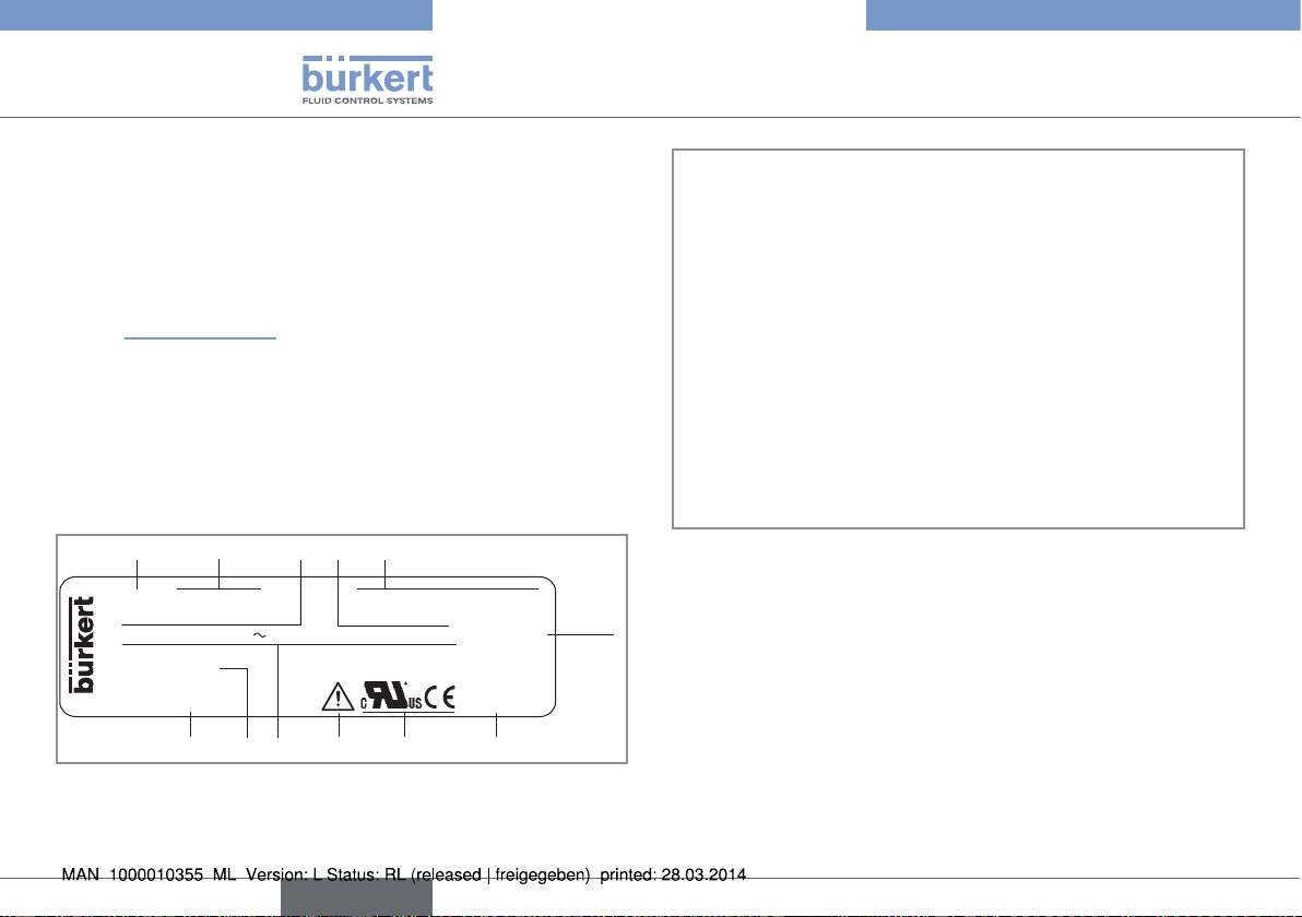
5.2 Description of the name plate
LFLOW 8025 PANEL SUPPLY: 12-36V= 210 mA
DO1: 5-36V= 100mA AO1:4-20mA
DO2&3: 2xRelay 30 and 42V peak or 60V... max. IP20
S/N 20 000
Made in France
00564417 W46MA
10
9
781112
6
1.▶ Measured▶value
2.▶ Type▶of▶the▶device,▶housing
3.▶ Specifications▶of▶the▶transistor▶output▶DO1
4.▶ Specifications▶of▶the▶analogue▶output▶AO1▶
5.▶ Supply▶voltage▶and▶max.▶current▶consumption
6.▶ Protection▶class▶of▶the▶device
7.▶ Manufacturing▶code
8.▶ Conformity▶logos
9.▶ Warning:▶Before▶using▶the▶device,▶take▶into▶account▶the▶technical▶specifications▶described▶in▶these▶operating▶instructions.
10.▶Specifications▶of▶the▶relay▶outputs▶DO2▶and▶DO3
11.▶Serial▶number
12.▶Order▶code
Fig. 1: Name plate of transmitter 8025 Universal (example)
6
English
Page 7
Type 8025 UNIVERSAL
Technical data
6 TECHNICAL DATA
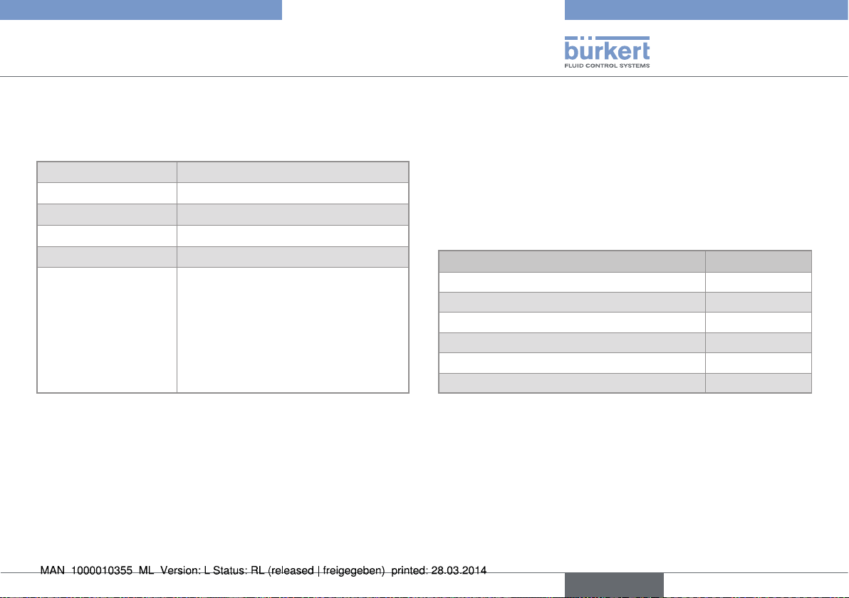
6.1 Conditions of use
Ambient▶temperature -10▶to▶+60▶°C
Air▶humidity <▶80▶%,▶non▶condensated
Height▶above▶sea▶level max.▶2000▶m
Installation▶class Class▶I▶acc.▶to▶UL▶61010-1
Degree▶of▶pollution Degree▶2▶acc.▶to▶EN▶61010-1
Protection▶rating
•▶ wall-mounted▶version▶
▶
▶
▶
•▶ panel▶version
6.2 Conformity to standards and
directives
The▶device▶conforms▶to▶the▶EC▶directives▶through▶the▶following▶
standards:
•▶ EMC:▶EN▶61000-6-2,▶EN▶61000-6-3
•▶ LVD:▶EN▶61010-1
•▶ Environnemental▶testing:
acc.▶to▶EN▶60529
•▶ IP65,▶device▶wired,▶cable▶glands▶
tightened,▶cover▶lid▶screwed▶tight▶and▶
entry▶item▶nuts▶of▶the▶cable▶glands▶
tightened▶at▶a▶screwing▶torque▶of▶
1.5▶Nm.
•▶ front▶side▶IP65,▶rear▶side▶IP20
▶- Vibration:▶EN▶60068-2-6,
▶- Shock:▶EN▶60068-2-27.
The▶UL▶devices▶with▶PU01▶variable▶key▶comply▶with▶the▶following▶
standards:
•▶ UL▶61010-1
•▶ CAN/CSA-C22.2▶n°▶61010-1
6.3 Mechanical data
Part Material
Housing▶and▶cover,▶wall-mounted▶version ABS
Cable▶glands,▶wall-mounted▶version PA
Open▶housing,▶panel▶version PC
Foil polyester
4▶screws Stainless▶steel
Cable▶clips PA
English
7
Page 8
Type 8025 UNIVERSAL
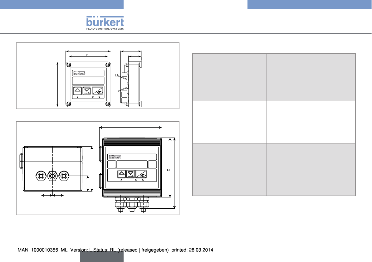
126
Technical data
88
76
FLOW
88
ENTER
0....9
40
25
Fig. 2: Dimensions of transmitter 8025 Universal, panel version [mm]
FLOW
120
23
23
90
31.50
0....9
ENTER
Fig. 3: Dimensions of transmitter 8025 Universal, wall-mounted
version [mm]
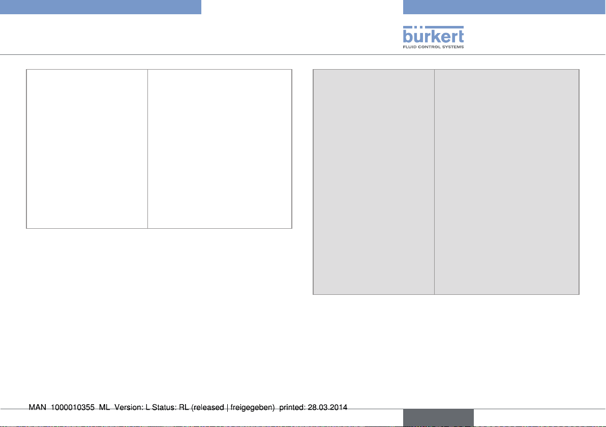
6.4 Electrical data
Power▶supply▶12-36▶V▶DC •▶ filtered▶and▶regulated
Power▶source▶(not▶provided) •▶ Source▶with▶limited▶power▶in▶
Power▶supply▶115/230▶V▶AC
•▶ frequency
•▶ supplied▶voltage
143
•▶ current
•▶ integrated▶protection
•▶ power
•▶ SELV▶circuit,▶with▶a▶safe▶energy▶
level
•▶ max.▶tolerance▶12▶V▶DC:▶-5▶%▶or▶
+10%
•▶ max.▶tolerance▶36▶V▶DC:▶±10▶%
accordance▶with▶§▶9.3▶of▶the▶
EN▶61010-1▶standard
•▶ or▶class▶2▶source▶in▶accordance▶
with▶the▶UL▶1310/1585▶and▶
EN▶60950-1▶standards
•▶ 50/60▶Hz
•▶ 27▶V▶DC,▶regulated
•▶ max.▶250▶mA
•▶ 250▶mA▶time▶delay▶fuse
•▶ 6▶VA
8
English
Page 9
Type 8025 UNIVERSAL
Technical data
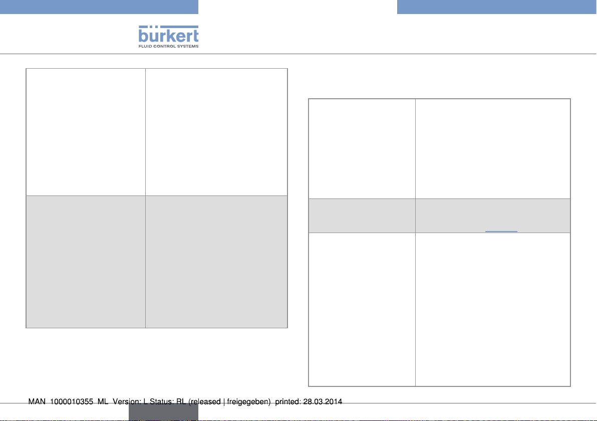
Current▶consumption▶
(without▶the▶consumption▶of▶
the▶4-20▶mA▶output)
•▶ version▶without▶
relays,▶energized▶with▶
12-36▶V▶DC
•▶ version▶with▶relays,▶energized▶with▶12-36▶V▶DC
•▶ version▶without▶
relays,▶energized▶with▶
115/230▶V▶AC
•▶ version▶with▶relays,▶energized▶with▶115/230▶V▶AC
▶
▶
•▶ 60▶mA▶(at▶12▶V▶DC)▶and▶30▶mA▶
(at▶36▶V▶DC)▶
•▶ 90▶mA▶(at▶12▶V▶DC)▶and▶45▶mA▶
(at▶36▶V▶DC)
•▶ 40▶mA▶
▶
•▶ 55▶mA
Transistor output DO1
•▶ type
•▶ function▶
•▶ frequency▶(f)
•▶ Electrical▶data▶
▶
•▶ duty▶cycle▶if▶
0,6▶<▶f▶<▶300▶Hz
•▶ duty▶cycle▶if▶
300▶<▶f▶<▶1500▶Hz
•▶ duty▶cycle▶if▶
1500▶<▶f▶<▶2200▶Hz
•▶ protection
polarized,▶potential-free
•▶ NPN▶/▶PNP▶(wiring▶dependent)
•▶ pulse▶output▶(by▶default),▶user▶
configurable
•▶ 0,6-2200▶Hz
•▶ 5-36▶V▶DC,▶100▶mA▶max.,▶
voltage▶drop▶2,7▶V▶DC▶at▶
100▶mA
•▶ >▶0.45▶
•▶ >▶0.4▶
•▶ <▶0.4▶
•▶ galvanically▶isolated,▶and▶
protected▶against▶overvoltages,▶polarity▶reversals▶and▶
short-circuits
English
9
Page 10
Type 8025 UNIVERSAL
Technical data
Relay outputs (DO2 and
DO3)
•▶ operating▶
•▶ electrical▶data▶of▶the▶load▶
(non▶UL▶devices)
•▶ electrical▶data▶of▶the▶load▶
(UL▶devices)
•▶ max.▶breaking▶capacity
•▶ life▶span
Current output AO1
•▶ specification▶
▶
•▶ max.▶loop▶impedance▶if▶the▶
device▶is▶energized▶with▶
12-36▶V▶DC▶
•▶ max.▶loop▶impedance▶if▶the▶
device▶is▶energized▶with▶
115/230▶V▶AC
▶
•▶ hysteresis▶(by▶default),▶user▶configurable,▶normally▶open
•▶ 230▶V▶AC▶/▶3▶A▶or▶
40▶V▶DC▶/▶3▶A
•▶ max.▶30▶V▶AC▶and▶42▶V▶peak▶or▶
max.▶60▶V▶DC,▶3▶A
•▶ 750▶VA▶(resistive▶load)
•▶ ▶min.▶100000▶cycles
•▶ 4-20▶mA,▶sink▶or▶source▶(wiring▶
dependent),▶22▶mA▶to▶indicate▶a▶
fault▶(can▶be▶activated)
•▶ 1300W▶at▶36▶V▶DC,▶1000W▶at▶
30▶V▶DC,▶750W▶at▶24▶V▶DC,▶
300W▶at▶15▶V▶DC,▶200W▶at▶
12▶V▶DC
•▶ 900W
6.5 Specifications of the connected
flow sensor
Signal▶originating▶from▶the▶
remote▶sensor
•▶ type▶
▶
▶
•▶ frequency
•▶ max.▶voltage
Input▶impedance
Power▶supply supplied▶by▶the▶transmitter▶depending▶
▶
•▶ pulse,▶sine-wave▶(typical▶sensitivity▶50▶mV▶peak-to-peak▶at▶250▶
Hz),▶"on/off",▶or▶standard▶voltage▶
0-5▶V▶DC
•▶ 0,6▶Hz▶to▶2,2▶kHz,▶can▶be▶adjusted
•▶ 36▶V▶DC
depends▶on▶the▶position▶of▶selector▶
"LOAD"▶on▶the▶electronic▶board▶of▶the▶
8025.▶See▶chap.▶„7.4.10“
on▶the▶position▶of▶selector▶"SENSOR▶
SUPPLY"▶of▶the▶8025,▶either:
•▶ 5▶V▶DC,▶30▶mA▶max.
•▶ (L+)-12V:▶supply▶voltage▶(L+)▶of▶the▶
transmitter▶minus▶12▶V▶DC▶(minus▶
12,5▶V▶DC▶max.),▶80▶mA▶max.
•▶ L+:▶supply▶voltage▶(L+)▶of▶the▶
transmitter▶(minus▶1,5▶V▶DC▶max.),▶
140▶mA▶max.▶(if▶the▶device▶is▶energized▶with▶12-36▶V▶DC),▶80▶mA▶
max.▶(if▶the▶device▶is▶energized▶with▶
115/230▶V▶AC)
10
English
Page 11
Type 8025 UNIVERSAL
Installation and wiring
6.6 Electrical connection
Type▶of▶connection on▶the▶terminal▶blocks▶of▶the▶
electronics▶(and▶through▶cable▶
glands▶M16x1,5,▶for▶the▶wallmounted▶versions)
Cable▶specifications
•▶ cable▶type
•▶ Cross▶section▶of▶wires
•▶ Diameter▶of▶each▶cable▶(for▶
the▶cable▶glands▶M16x1,5▶of▶
the▶wall-mounted▶version)
•▶ shielded
•▶ 0.2▶to▶1.5▶mm
•▶ 4▶to▶8▶mm
2
7 INSTALLATION AND WIRING
7.1 Safety instructions
danger
Risk of injury due to electrical voltage.
▶▶ Shut▶down▶the▶electrical▶power▶source▶of▶all▶the▶conductors▶and▶
isolate▶it▶before▶carrying▶out▶work▶on▶the▶system.
▶▶ Observe▶all▶applicable▶accident▶protection▶and▶safety▶regula-
tions▶for▶electrical▶equipment.
Warning
Risk of injury due to non-conforming installation.
▶▶ The▶electrical▶installation▶can▶only▶be▶carried▶out▶by▶qualified▶
and▶skilled▶staff▶with▶the▶appropriate▶tools.
▶▶ Install▶appropriate▶safety▶devices▶(correctly▶rated▶fuse▶and/or▶
circuit-breaker);▶For▶the▶versions▶with▶a▶115/230▶V▶AC▶supply▶voltage,▶insert▶a▶safety▶device▶between▶the▶phase▶and▶the▶
neutral▶conductor.
▶▶ Respect▶standard▶NF▶C▶15-100▶/▶IEC▶60364.
Risk of injury due to unintentional switch on of power supply
or uncontrolled restarting of the installation.
▶▶ Take▶appropriate▶measures▶to▶avoid▶unintentional▶activation▶of▶
the▶installation.
▶▶ Guarantee▶a▶set▶or▶controlled▶restarting▶of▶the▶process▶subse-
quent▶to▶any▶intervention▶on▶the▶device.
English
11
Page 12
Type 8025 UNIVERSAL
Installation and wiring
Protect▶this▶device▶against▶electromagnetic▶interference,▶
ultraviolet▶rays▶and,▶when▶installed▶outdoors,▶the▶effects▶of▶
the▶climatic▶conditions.
7.2 Installation of a panel version
Install▶the▶panel▶version▶of▶the▶device▶in▶a▶cabinet▶with▶a▶
protection▶class▶at▶least▶IP54▶to▶ensure▶a▶degree▶of▶pollution▶2▶inside▶the▶cabinet.
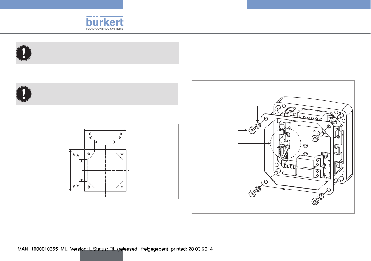
▶→ To▶cut▶the▶opening▶in▶the▶cabinet▶door,▶use▶the▶supplied▶drilling▶
jig,▶respecting▶the▶dimensions▶indicated▶in▶„Fig.▶4“.
95
80
76
50
95
80
76
50
Fig. 4: Dimensions of the drilling jig [mm]
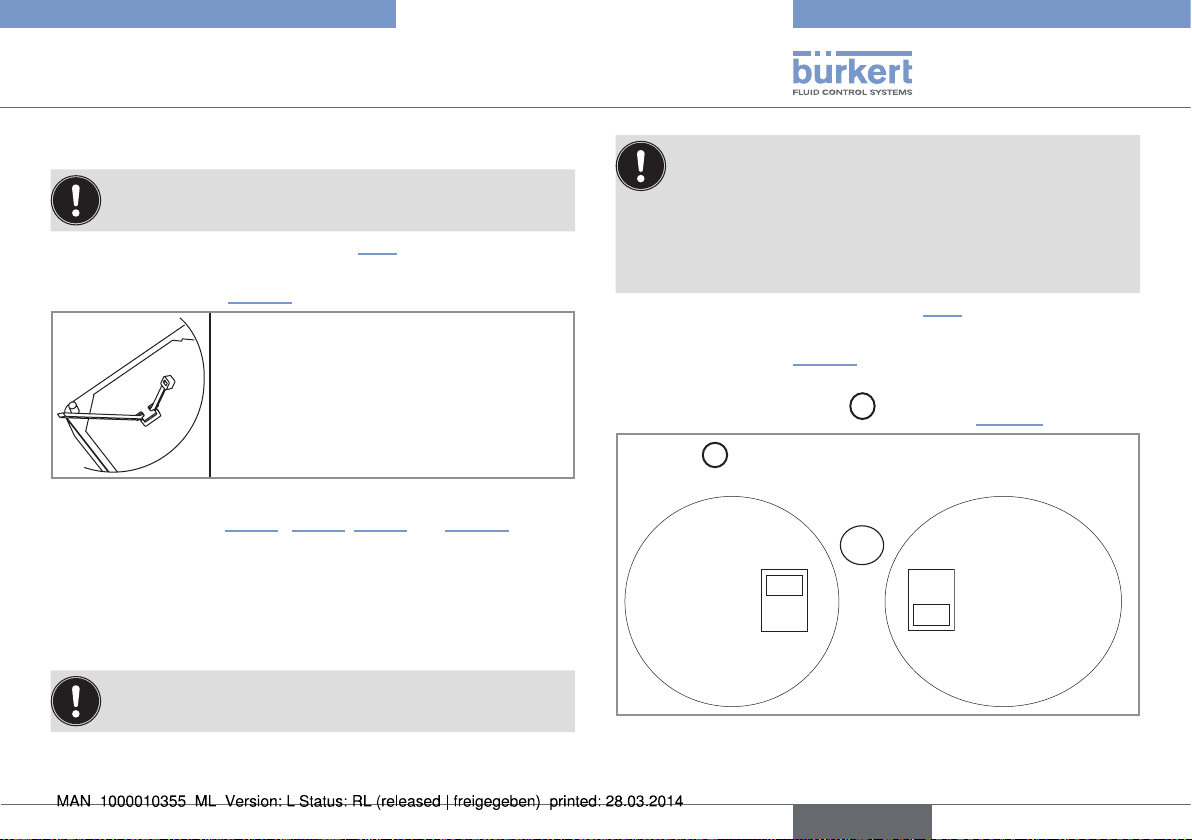
▶→ Insert▶the▶4▶screws▶in▶the▶housing▶(from▶the▶front).
▶→ Insert▶the▶seal▶on▶the▶external▶threads▶of▶the▶4▶screws▶(rear▶of▶
the▶housing).
▶→ Put▶the▶assembly▶on▶the▶cutout,▶electronics▶turned▶to▶the▶inside▶
of▶the▶cabinet.
▶→ Put▶the▶4▶washers▶on▶the▶4▶screws.
▶→ Put▶a▶nut▶on▶each▶of▶the▶4▶screws▶and▶tighten▶the▶nuts▶to▶secure▶
the▶device▶to▶the▶cabinet.
Screws
Washer
Nut
Cable▶clip
Seal
Fig. 5: Installation of a 8025, panel version
12
English
Page 13
Type 8025 UNIVERSAL
11
Installation and wiring
7.3 Installation of a wall-mounted
version
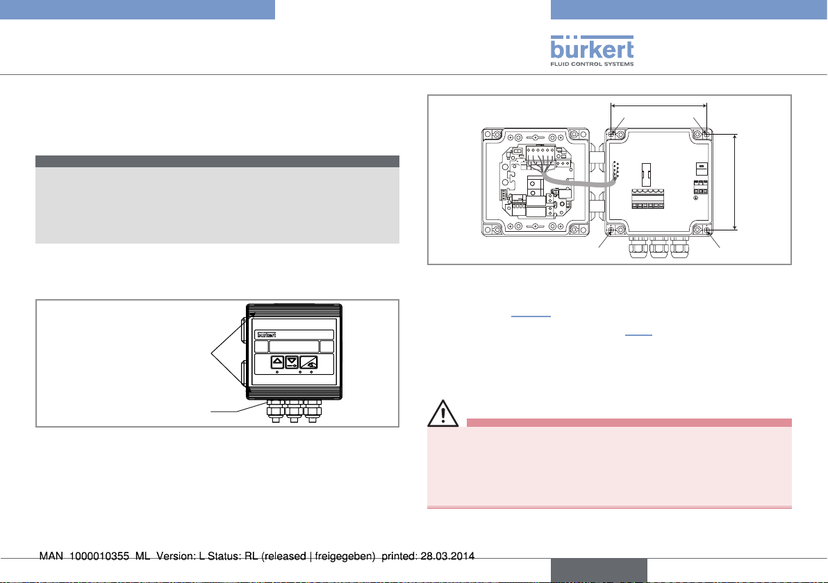
note
Risk of material damage if the cable glands are not tightly
screwed on the housing
▶▶ Before▶installing▶the▶wall-mounted▶housing▶on▶its▶support,▶
tighten▶the▶nuts▶of▶the▶entry▶item▶of▶the▶cables▶glands▶at▶a▶torque▶
of▶1.5▶Nm.
The▶flow▶transmitter▶in▶a▶wall-mounted▶version▶has▶4▶holes▶in▶the▶
bottom▶of▶the▶housing.
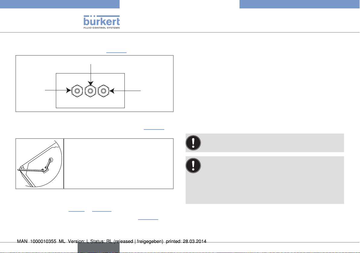
▶→ Remove▶the▶blanking▶strips▶covering▶the▶screws.
FLOW
Blanking▶strips
Nut▶of▶the▶entry▶item
▶→ Loosen▶the▶4▶screws▶and▶open▶the▶cover▶to▶get▶access▶to▶the▶holes▶[1].
ENTER
0....9
106 mm
SOURCE SINK
CURRENT
BINARY
Iout
L+ L- PE P- P+
Univ
(AO1)
PULSE
Supply
Batch
DO1
12..36Vdc
NC
PE
ISOG
DO4
DI4
DI3
DI2
DI1
INPUT
PULSE
FLOW
SENSOR
PE PEPE
SENSOR
+5V
L+
SENSOR TYPE
SUPPLY
(L+)-12V
COIL NPN/PNP
COIL/PNP
470
2.2K
39K
LOAD
SUPPLY
+-
NC
COIL
213PE
OFFON
NPN/PNP
DO2
DO3
T 250 mA
56789 10
230V
230V
230V
106 mm
LN
LN
1 1
Fig. 6: Installation of a wall-mounted version
▶→ Secure▶the▶housing▶to▶the▶support▶respecting▶the▶dimensions▶
indicated▶in▶„Fig.▶6“.
▶→ Wire▶acc.▶to▶instructions▶in▶chap.▶„7.4“.
▶→ Close▶the▶housing▶and▶tighten▶the▶4▶screws▶of▶the▶cover.
7.4 Wiring
danger
Risk of injury due to electrical voltage.
▶▶ Shut▶down▶the▶electrical▶power▶source▶of▶all▶the▶conductors▶and▶
isolate▶it▶before▶carrying▶out▶work▶on▶the▶system.
▶▶ Observe▶all▶applicable▶accident▶protection▶and▶safety▶regula-
tions▶for▶electrical▶equipment.
English
13
Page 14
Type 8025 UNIVERSAL
Installation and wiring
Insert▶the▶supplied▶stopper▶gaskets▶into▶the▶unused▶cable▶
glands▶of▶a▶wall-mounted▶version▶to▶ensure▶the▶tightness▶of▶
the▶device.
Only▶move▶the▶selectors▶when▶the▶power▶supply▶is▶off.
•▶ Use▶a▶filtered▶and▶regulated▶12-36▶V▶DC▶power▶supply.
•▶ Make▶sure▶the▶installation▶is▶equipotential.▶See▶chap.▶
„7.4.1“.
•▶ Use▶shielded▶cables▶with▶a▶temperature▶limit▶of▶80▶°C▶
minimum.
•▶ Do▶not▶install▶the▶cables▶near▶high▶voltage▶or▶high▶frequency▶cables;▶If▶this▶cannot▶be▶avoided,▶observe▶a▶min.▶
distance▶of▶30▶cm.
•▶ Protect▶the▶device▶power▶supply▶by▶means▶of▶a▶300▶mA▶
fuse▶and▶a▶switch.
•▶ Protect▶the▶power▶supply▶of▶each▶transistor▶output▶by▶
means▶of▶a▶125▶mA▶fuse.
•▶ Protect▶the▶relays▶by▶means▶of▶a▶max.▶3▶A▶fuse▶and▶a▶
circuit▶breaker▶(depending▶on▶the▶process).
•▶ Do▶not▶apply▶both▶a▶dangerous▶voltage▶and▶a▶safety▶extralow▶voltage▶to▶the▶relays.
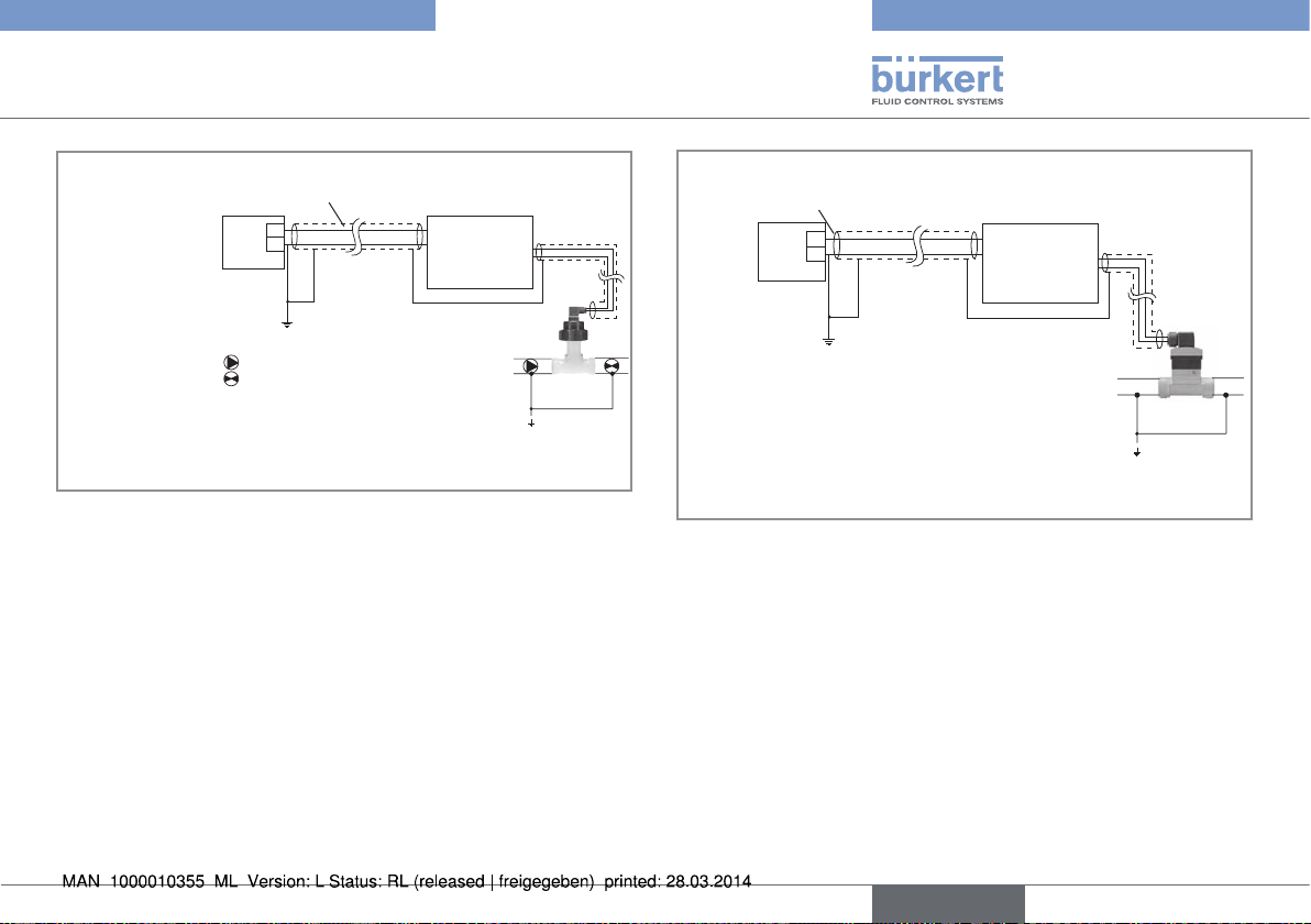
7.4.1 Equipotentiality of the installation
To▶ensure▶the▶equipotentiality▶of▶the▶installation▶(power▶supply▶-▶
device▶-▶fluid):
▶→ Connect▶together▶the▶various▶earth▶spots▶in▶the▶installation▶to▶
eliminate▶the▶potential▶differences▶that▶may▶occur▶between▶different▶earthes.
▶→ Observe▶faultless▶earthing▶of▶the▶shield▶of▶the▶power▶supply▶
cable,▶at▶both▶ends.
▶→ Connect▶the▶negative▶power▶supply▶terminal▶to▶the▶earth▶to▶sup-
press▶the▶effects▶of▶common▶mode▶currents.▶If▶this▶connection▶
cannot▶be▶made▶directly,▶a▶100▶nF/50▶V▶capacitor▶can▶be▶fitted▶
between▶the▶negative▶power▶supply▶terminal▶and▶the▶earth.▶
▶→ Special▶attention▶has▶to▶be▶paid▶if▶the▶device▶is▶installed▶on▶
plastic▶pipes▶because▶there▶is▶no▶direct▶earthing▶possible.▶
Proper▶earthing▶is▶performed▶by▶earthing▶together▶the▶metallic▶
instruments▶such▶as▶pumps▶or▶valves,▶that▶are▶as▶close▶as▶possible▶to▶the▶device.▶If▶no▶such▶instrument▶is▶near▶the▶device,▶
insert▶metallic▶earth▶rings▶inside▶the▶plastic▶pipes▶upstream▶and▶
downstream▶the▶device▶and▶connect▶these▶parts▶to▶the▶same▶
earth.▶The▶earthing▶rings▶must▶be▶in▶contact▶with▶the▶fluid.
14
English
Page 15
Type 8025 UNIVERSAL
Installation and wiring
Power▶cable▶shield
+
-
Power▶supply
Valve,▶pump,...▶(or▶earth▶
rings,▶not▶provided,▶
inserted▶into▶the▶pipe)▶
(*)▶
If▶a▶direct▶earth▶connection▶is▶not▶possible,▶fit▶a▶100▶nF▶/▶50▶V▶capacitor▶
(*)
8025▶Universal
Flow▶sensor
Plastic▶pipe
between▶the▶negative▶power▶supply▶terminal▶and▶the▶earth.
Fig. 7: Equipotentiality skeleton diagram with pipes in plastic
Power▶cable▶shield
+
-
Power▶supply
(*)▶
If▶a▶direct▶earth▶connection▶is▶not▶possible,▶fit▶a▶100▶nF▶/▶50▶V▶capacitor▶
(*)
8025▶Universal
Flow▶sensor
Metal▶pipe
between▶the▶negative▶power▶supply▶terminal▶and▶the▶earth.
Fig. 8: Equipotentiality skeleton diagram with pipes in metal
English
15
Page 16
Type 8025 UNIVERSAL
1
Installation and wiring
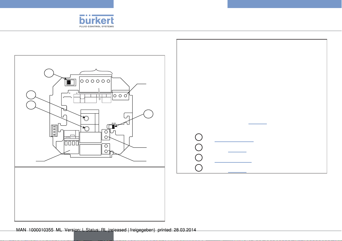
7.4.2 Terminal assignment and use of the
selectors
A
2
SOURCESINK
CURRENT
BINARY
Iout
L+ L- PE P- P+
FLOW
PULSE
PE
ISOG
DO4
DI4
DI3
DI2
DI1
INPUT
Univ
Batch
SUPPLY
+-
NC
213PE
COIL
(AO1)
NC
L+
2.2K
NPN/PNP
Supply
12..36Vdc
SENSOR
+5V
(L+)-12V
470
39K
SUPPLY
COIL/PNP
LOAD
PULSE
DO1
SENSOR TYPE
COIL NPN/PNP
DO2
DO3
PE PEPE
D
OFF ON
3
4
B
C
SENSOR
5
Terminal block 1
•▶ Iout:▶4-20▶mA▶output▶(AO1)
•▶ L+:▶V+▶(positive▶voltage)
•▶ L-:▶0V▶(power▶supply▶ground)
•▶ PE:▶protective▶earth,▶factory▶wired
•▶ P-:▶Negative▶transistor▶output▶(DO1)
•▶ P+:▶Positive▶transistor▶output▶(DO1)
Terminal block 2
PE:▶Shieldings▶of▶both▶the▶power▶supply▶cable▶and▶the▶AO1▶and▶
DO1▶output▶cables
Terminal block 3:▶Wiring▶of▶the▶relay▶output▶DO2▶(if▶the▶device▶
has▶relays).
Terminal block 4:▶Wiring▶of▶the▶relay▶output▶DO3▶(if▶the▶device▶
has▶relays).
Terminal block 5 "FLOW SENSOR": Wiring▶the▶remote▶flow▶
sensor.▶The▶wiring▶depends▶on▶the▶type▶of▶output▶signal▶originating▶
from▶the▶flow▶sensor:▶see▶chap.▶„7.4.10“.
Switch▶
Switch▶
Switch▶
Switch▶
A
:▶see▶„Fig.▶15“▶page▶21
B
:▶see▶chap.▶„7.4.10“
C
:▶see▶„Tab.▶1“▶page▶29
D
:▶see▶chap.▶„7.4.10“
Fig. 9: Terminal assignment of a panel version or a wall-mounted
version, 12-36 V DC
16
English
Page 17
Type 8025 UNIVERSAL
Installation and wiring
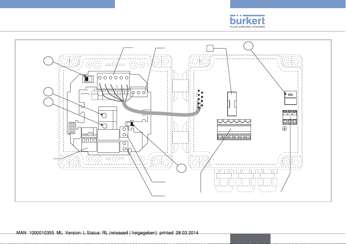
2
1
8
E
A
SOURCESINK
CURRENT
BINARY
Iout
L+ L- PE P- P+
FLOW
PULSE
PE
ISOG
DO4
DI4
DI3
DI2
DI1
INPUT
SUPPLY
+-
NC
213PE
Univ
Batch
COIL
(AO1)
NC
L+
2.2K
NPN/PNP
Supply
12..36Vdc
SENSOR
+5V
(L+)-12V
470
39K
SUPPLY
COIL/PNP
LOAD
PULSE
DO1
SENSOR TYPE
COIL NPN/PNP
DO2
DO3
PE PEPE
230V
230V
230V
T 250 mA
LN
OFF ON
56789 10
LN
B
C
SENSOR
3
D
4
5
6 7
English
17
Page 18
Type 8025 UNIVERSAL
Installation and wiring
Terminal block 1
PE:▶factory▶wired▶shield.
Terminal block 2
•▶ Iout:▶4-20▶mA▶output▶(green▶wire,▶factory▶wired)
•▶ L+:▶V+▶(red▶wire,▶factory▶wired)
•▶ L-:▶0V▶(black▶wire,▶factory▶wired)
•▶ PE:▶protective▶earth,▶factory▶wired
•▶ P-:▶negative▶transistor▶output▶(brown▶wire,▶factory▶wired)
•▶ P+:▶positive▶transistor▶output▶(white▶wire,▶factory▶wired)
Terminal block 3 "FLOW SENSOR": Wiring▶the▶remote▶flow▶sensor.▶
The▶wiring▶depends▶on▶the▶type▶of▶output▶signal▶originating▶from▶the▶
flow▶sensor:▶see▶chap.▶„7.4.10“.
Switch▶
Switch▶
Switch▶
Switch▶
Switch▶
Fig. 10: Terminal assignment of a wall-mounted version, 115/230 V AC
A
:▶see▶„Fig.▶15“▶page▶21
B
:▶see▶chap.▶„7.4.10“
C
:▶see▶„Tab.▶1“▶page▶29
D
:▶see▶chap.▶„7.4.10“
E
:▶see▶chap.▶„7.4.4“
Terminal block 4:▶Wiring▶of▶the▶relay▶output▶DO2▶(if▶the▶device▶has▶
relays).
Terminal block 5:▶Wiring▶of▶the▶relay▶output▶DO3▶(if▶the▶device▶has▶
relays).
Terminal block 6
•▶ Terminal▶5:▶4-20▶mA▶output▶(AO1)
•▶ Terminal▶6:▶positive▶27▶V▶DC▶power▶supply,▶available▶to▶energize▶an▶
external▶instrument
•▶ Terminal▶7:▶0V▶(earth▶of▶the▶power▶supply▶available▶to▶energize▶an▶
external▶instrument)
•▶ Terminal▶8:▶protective▶earth:▶shields▶of▶the▶AO1▶and▶DO1▶output▶
cables
•▶ Terminal▶9:▶Negative▶transistor▶output▶(DO1)
•▶ Terminal▶10:▶Positive▶transistor▶output▶(DO1)
Terminal block 7:▶Wiring▶of▶the▶115/230▶V▶AC▶power▶supply▶
8
Mark▶
:▶time-delay▶fuse▶to▶protect▶the▶115/230▶V▶AC▶power▶supply
18
English
Page 19
Type 8025 UNIVERSAL
Installation and wiring
7.4.3 Wiring a panel version
Only▶move▶the▶selectors▶when▶the▶power▶supply▶is▶off.
▶→ Install▶the▶device▶as▶described▶in▶chap.▶„7.2“.
▶→ Set▶the▶selectors▶"SENSOR▶TYPE",▶"SENSOR▶SUPPLY"▶and▶
"LOAD":▶see▶chap.▶„7.4.10“.
▶→ Before▶wiring▶the▶device▶insert▶the▶sup-
plied▶cable▶clips▶into▶the▶slots▶of▶the▶electronic▶board.
Fig. 11: Inserting the cable clips
▶→ Wire▶acc.▶to▶chap.▶„7.4.5“▶,▶„7.4.6“,▶„7.4.9“▶and▶„7.4.10“.▶
▶→ Secure▶the▶power▶supply▶cable,▶the▶flow▶sensor▶connection▶
cable▶and,▶depending▶on▶the▶version,▶the▶relay▶connection▶
cables,▶with▶the▶cable▶clips.
7.4.4 Wiring a wall-mounted version
Only▶move▶the▶selectors▶when▶the▶power▶supply▶is▶off.
Insert▶the▶supplied▶stopper▶gaskets▶into▶the▶unused▶cable▶
glands▶to▶ensure▶the▶tightness▶of▶the▶device.
•▶ Unscrew▶the▶unused▶cable▶gland.
•▶ Remove▶the▶transparent▶disk.
•▶ Insert▶the▶supplied▶stopper▶gasket.
•▶ Screw▶the▶nut▶of▶the▶cable▶gland.
▶→ Install▶the▶device▶as▶described▶in▶chap.▶„7.3“.
▶→ Set▶the▶selectors▶"SENSOR▶TYPE",▶"SENSOR▶SUPPLY"▶and▶
"LOAD":▶see▶chap.▶„7.4.10“.
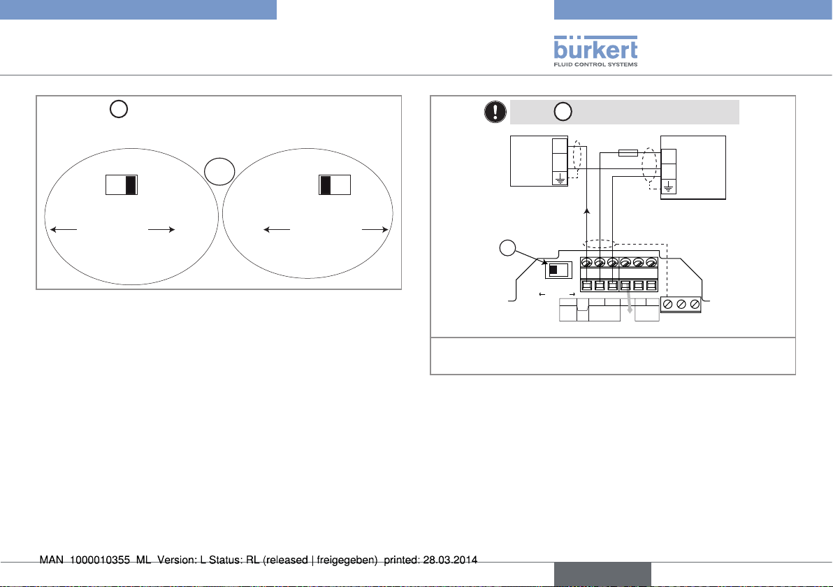
▶→ If▶the▶wall-mounted▶version▶is▶energized▶with▶a▶115/230▶V▶AC▶
E
power▶supply,▶set▶selector▶
E
Selector▶
▶makes▶it▶possible▶to▶configure▶the▶supply▶volt-
▶as▶shown▶in▶„Fig.▶12“.
age▶of▶the▶device▶in▶a▶115/230▶V▶AC▶version.
E
▶→ Energize▶the▶
device▶with▶
a▶230▶V▶AC▶
voltage.
Fig. 12: Selector of the supply voltage on a 115/230 V AC version
230V
▶→ Loosen▶the▶nuts▶of▶the▶cable▶glands.
▶→ Energize▶the▶
115V
device▶with▶
a▶115▶V▶AC▶
voltage.
English
19
Page 20
Type 8025 UNIVERSAL
Installation and wiring
▶→ Insert▶each▶cable▶through▶a▶nut▶than▶through▶the▶cable▶gland,▶
using▶the▶cable▶glands▶as▶shown▶in▶„Fig.▶13“.
Cables▶of▶the▶outputs
Flow▶sensor▶cable
Fig. 13: Using the cable glands
Power▶supply▶cable▶
12-36▶V▶DC▶or▶
115/230▶V▶AC
▶→ Remove▶the▶two▶terminal▶blocks▶(marked▶6▶and▶7▶in▶„Fig.▶10“)▶
from▶the▶housing.
▶→ Before▶wiring▶the▶device▶insert▶the▶sup-
plied▶cable▶clips▶into▶the▶slots▶of▶the▶electronic▶board▶and▶of▶the▶115/230▶V▶AC▶
power▶supply▶board▶if▶the▶device▶has▶such▶
a▶board.
Fig. 14: Inserting the cable clips
▶→ Depending▶on▶the▶operating▶voltage▶of▶the▶device,▶wire▶
according▶to▶chap.▶„7.4.5“▶to▶„7.4.10“.
▶→ Insert▶the▶two▶terminal▶blocks▶(marked▶6▶and▶7▶in▶„Fig.▶10“)▶into▶
their▶original▶position.
▶→ Letting▶the▶housing▶stay▶completely▶open,▶secure▶the▶power▶
supply▶cable,▶the▶flow▶sensor▶connection▶cable▶and,▶depending▶
on▶the▶version,▶the▶relay▶connection▶cables,▶with▶the▶cable▶clips.
▶→ Tighten▶the▶cable▶glands▶making▶sure▶the▶cable▶in▶the▶housing▶is▶
long▶enough▶to▶allow▶complete▶opening▶of▶the▶housing.
▶→ Close▶the▶cover.
▶→ Tighten▶the▶4▶screws.
▶→ Put▶the▶blanking▶strips▶on▶the▶housing.
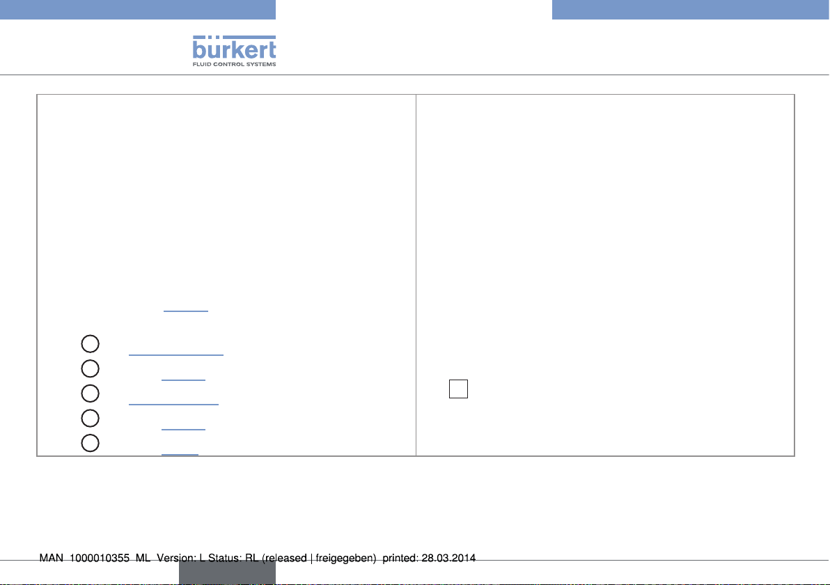
7.4.5 Wiring the AO1 current output of a
panel version or a wall-mounted
version, 12-36 V DC
Only▶move▶the▶selectors▶when▶the▶power▶supply▶is▶off.
Insert▶the▶supplied▶stopper▶gaskets▶into▶the▶unused▶cable▶
glands▶to▶ensure▶the▶tightness▶of▶the▶device.
•▶ Unscrew▶the▶unused▶cable▶gland.
•▶ Remove▶the▶transparent▶disk.
•▶ Insert▶the▶supplied▶stopper▶gasket.
•▶ Screw▶the▶nut▶of▶the▶cable▶gland.
The▶4-20▶mA▶output▶can▶be▶wired▶in▶either▶sourcing▶or▶sinking▶
mode.
20
English
Page 21
Type 8025 UNIVERSAL
12-36 V DC
Installation and wiring
A
Use▶switch▶
▶to▶configure▶the▶wiring▶of▶the▶4-20▶mA▶cur-
rent▶output▶in▶sinking▶or▶sourcing▶mode.
A
SOURCE SINK
CURRENT
▶→ Wire▶the▶current▶output▶in▶
sinking▶mode.
Fig. 15: Using the sink/source switch
▶→ Wire▶the▶current▶output▶
in▶sourcing▶mode.
SOURCE SINK
CURRENT
Set▶the▶A▶switch▶on▶the▶left.▶
300 mA
I
Iout
L+ L- PE P- P+
(AO1)
Supply
12..36Vdc
NC
(*)
PULSE
DO1
+
-
Power▶supply
PE PEPE
4-20mA▶input▶at▶external▶
A
instrument
SOURCESINK
CURRENT
+
-
Univ
Batch
*)▶If▶a▶direct▶earth▶connection▶is▶not▶possible,▶fit▶a▶100▶nF/50▶V▶
capacitor▶between▶the▶negative▶power▶supply▶terminal▶and▶the▶earth
Fig. 16: Wiring of the 4-20 mA output (AO1) in sourcing mode
English
21
Page 22
Set▶the▶A▶switch▶on▶the▶right.
4-20mA▶input▶at▶external▶
instrument
A
Type 8025 UNIVERSAL
Installation and wiring
7.4.6 Wiring the DO1 transistor output of
a panel version or a wall-mounted
+
300 mA
-
I
12-36 V DC
+
-
(*)
Power▶supply
version, 12-36 V DC
Insert▶the▶supplied▶stopper▶gaskets▶into▶the▶unused▶cable▶
glands▶to▶ensure▶the▶tightness▶of▶the▶device.
•▶ Unscrew▶the▶unused▶cable▶gland.
•▶ Remove▶the▶transparent▶disk.
•▶ Insert▶the▶supplied▶stopper▶gasket.
•▶ Screw▶the▶nut▶of▶the▶cable▶gland.
SOURCESINK
CURRENT
Iout
L+ L- PE P- P+
Univ
Batch
(AO1)
NC
Supply
12..36Vdc
PULSE
DO1
PE PEPE
*)▶If▶a▶direct▶earth▶connection▶is▶not▶possible,▶fit▶a▶100▶nF/50▶V▶
capacitor▶between▶the▶negative▶power▶supply▶terminal▶and▶the▶earth
Fig. 17: Wiring of the 4-20 mA output (AO1) in sinking mode
22
English
12-36 V DC
Power▶supply▶of▶
the▶device
300 mA
+
-
(*)
+
5-36 VDC
-
+
-
PLC
Iout
L+ L- PE P- P+
Univ
Batch
(AO1)
NC
12..36Vdc
Supply
PULSE
DO1
PE PEPE
*)▶If▶a▶direct▶earth▶connection▶is▶not▶possible,▶fit▶a▶100▶nF/50▶V▶
capacitor▶between▶the▶negative▶power▶supply▶terminal▶and▶the▶earth
Fig. 18: NPN wiring of the DO1 transistor output
Page 23
Type 8025 UNIVERSAL
Installation and wiring
12-36 V DC
Power▶supply▶of▶
the▶device
+
-
(*)
Univ
Batch
300 mA
Iout
L+ L- PE P- P+
(AO1)
Supply
12..36Vdc
NC
PULSE
DO1
PE PEPE
+
5-36 VDC
-
+
-
PLC
*)▶If▶a▶direct▶earth▶connection▶is▶not▶possible,▶fit▶a▶100▶nF/50▶V▶
capacitor▶between▶the▶negative▶power▶supply▶terminal▶and▶the▶earth
Fig. 19: PNP wiring of the DO1 transistor output
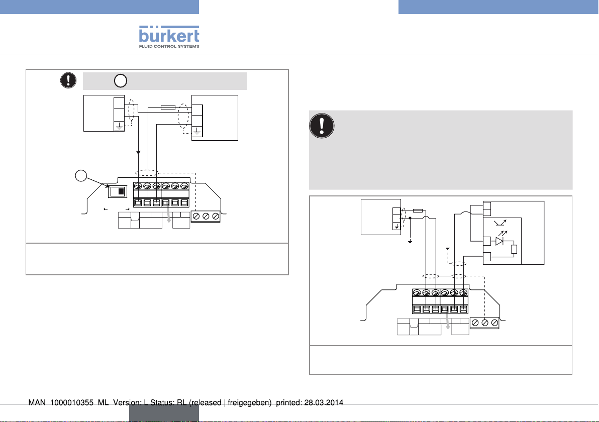
7.4.7 Wiring the AO1 current output of a wall-mounted version, 115/230 V AC
Insert▶the▶supplied▶stopper▶gaskets▶into▶the▶unused▶cable▶glands▶to▶ensure▶the▶tightness▶of▶the▶device.
•▶ Unscrew▶the▶unused▶cable▶gland.
•▶ Remove▶the▶transparent▶disk.
•▶ Insert▶the▶supplied▶stopper▶gasket.
•▶ Screw▶the▶nut▶of▶the▶cable▶gland.
English
23
Page 24
Only▶move▶the▶selectors▶when▶the▶power▶supply▶is▶off.
230V
LN
230V
T 250 mA
56789 10
LN
230V
A
CURRENT
SOURCESINK
BINARY
PE PEPE
PE
DI1
DI2
DI3
DI4
DO4
ISOG
FLOW
SENSOR
L+ L- PE P- P+
NC
Iout
PULSE
DO1
Supply
12..36Vdc
Univ
Batch
(AO1)
SUPPLY
NC
COIL
PULSE
INPUT
NPN/PNP
213PE
+-
SENSOR
SUPPLY
LOAD
+5V
L+
(L+)-12V
COIL/PNP
39K
470
2.2K
SENSOR TYPE
COIL NPN/PNP
DO2
DO3
OFFON
E
+
-
The▶4-20▶mA▶output▶can▶be▶wired▶in▶either▶sourcing▶or▶sinking▶mode.
•▶ Set▶the▶A▶switch▶on▶the▶left.
E
•▶ Set▶selector▶
▶▶▶
▶depending▶on▶the▶value▶of▶the▶power▶supply.
4-20mA▶input▶at▶external▶instrument
Type 8025 UNIVERSAL
Installation and wiring
Connection▶of▶the▶power▶
supply▶for▶the▶8025
Fig. 20: Wiring of the 4-20 mA output (AO1) of a wall-mounted version, 115/230 V AC, in sourcing mode
24
English
Page 25
Type 8025 UNIVERSAL
230V
LN
230V
T 250 mA
56789 10
LN
230V
A
CURRENT
SOURCESINK
BINARY
PE PEPE
PE
DI1
DI2
DI3
DI4
DO4
ISOG
FLOW
SENSOR
L+ L- PE P- P+
NC
Iout
PULSE
DO1
Supply
12..36Vdc
Univ
Batch
(AO1)
SUPPLY
NC
COIL
PULSE
INPUT
NPN/PNP
213PE
+-
SENSOR
SUPPLY
LOAD
+5V
L+
(L+)-12V
COIL/PNP
39K
470
2.2K
SENSOR TYPE
COIL NPN/PNP
DO2
DO3
OFFON
E
+
-
Installation and wiring
•▶ Set▶the▶A▶switch▶on▶the▶right.
E
•▶ Set▶selector▶
▶▶▶
▶depending▶on▶the▶value▶of▶the▶power▶supply.
Fig. 21: Wiring of the 4-20 mA output (AO1) of a wall-mounted version, 115/230 V AC, in sinking mode
4-20mA▶input▶at▶external▶instrument
Connection▶of▶the▶power▶
supply▶for▶the▶8025
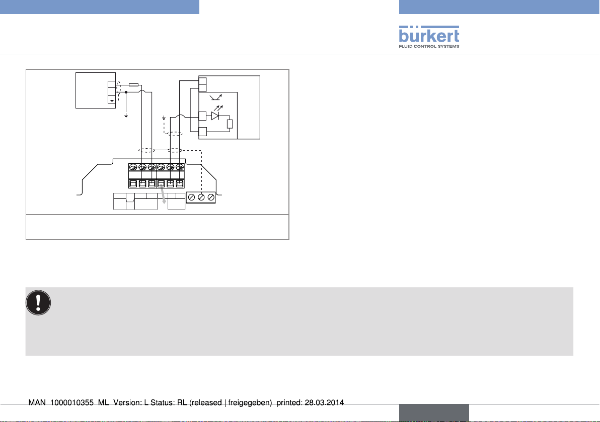
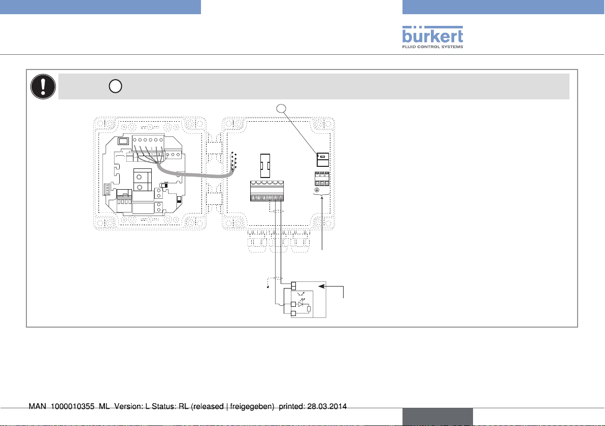
7.4.8 Wiring the DO1 transistor output of a wall-mounted version, 115/230 V AC
Only▶move▶the▶selectors▶when▶the▶power▶supply▶is▶off.
English
25
Page 26
Type 8025 UNIVERSAL
Installation and wiring
Insert▶the▶supplied▶stopper▶gaskets▶into▶the▶unused▶cable▶glands▶to▶ensure▶the▶tightness▶of▶the▶device.
•▶ Unscrew▶the▶unused▶cable▶gland.
•▶ Remove▶the▶transparent▶disk.
•▶ Insert▶the▶supplied▶stopper▶gasket.
•▶ Screw▶the▶nut▶of▶the▶cable▶gland.
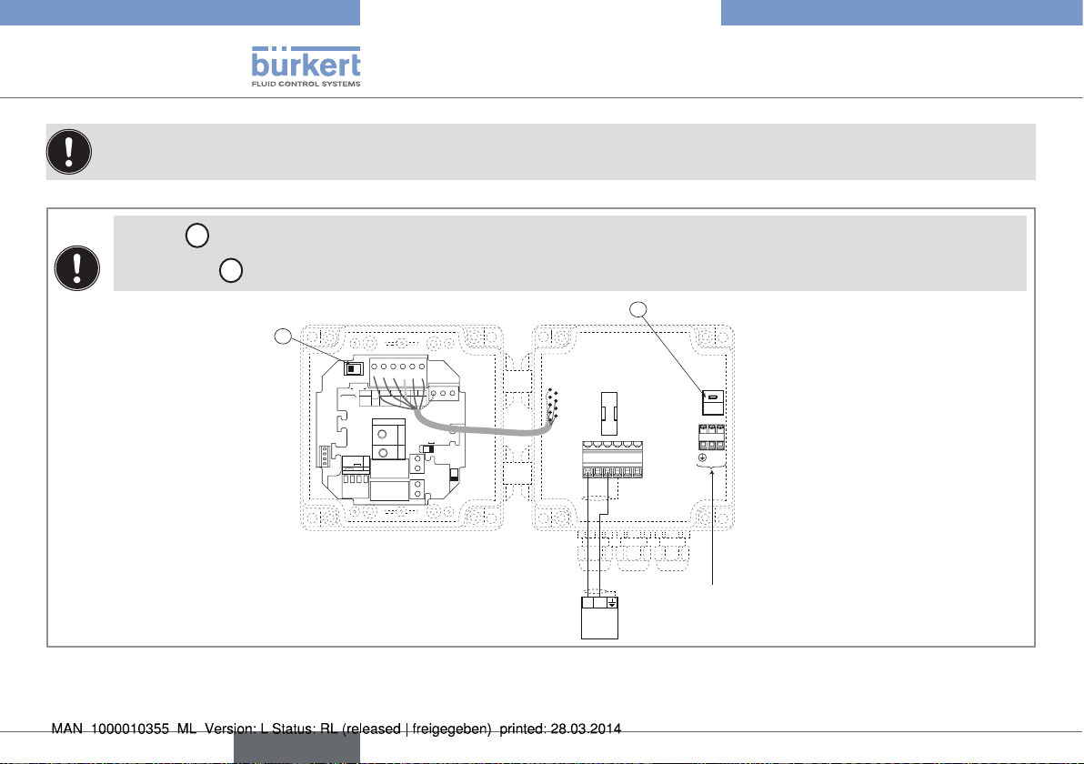
Set▶of▶selector▶E▶depending▶on▶the▶value▶of▶the▶power▶supply.
▶
E
SOURCESINK
CURRENT
BINARY
Iout
L+ L- PE P- P+
Univ
(AO1)
PULSE
Supply
Batch
DO1
12..36Vdc
SENSOR
NC
PE
ISOG
DO4
DI4
DI3
L+
DI2
DI1
2.2K
SUPPLY
INPUT
+-
NPN/PNP
PULSE
NC
COIL
213PE
FLOW
SENSOR
+5V
(L+)-12V
470
PE PEPE
SENSOR TYPE
SUPPLY
COIL NPN/PNP
COIL/PNP
39K
LOAD
OFFON
DO2
DO3
T 250 mA
56789 10
230V
230V
230V
LN
LN
Connection▶of▶the▶power▶supply▶for▶the▶8025
PLC
+
5-36 VDC
-
+
-
Power▶supply▶for▶the▶PLC
Fig. 22: NPN wiring of the DO1 transistor output of a wall-mounted version, 115/230 V AC
26
English
Page 27
Type 8025 UNIVERSAL
Installation and wiring
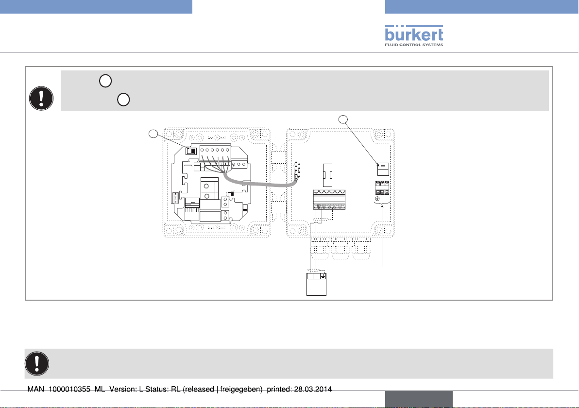
Set▶selector▶E▶depending▶on▶the▶value▶of▶the▶power▶supply.
▶
E
SOURCESINK
CURRENT
BINARY
Iout
L+ L- PE P- P+
Univ
(AO1)
PULSE
Supply
Batch
DO1
12..36Vdc
FLOW
SENSOR
NC
PE
ISOG
DO4
DI4
DI3
L+
DI2
DI1
2.2K
SUPPLY
INPUT
+-
NPN/PNP
PULSE
NC
COIL
213PE
SENSOR
+5V
(L+)-12V
470
39K
COIL/PNP
SUPPLY
LOAD
PE PEPE
SENSOR TYPE
COIL NPN/PNP
DO2
DO3
T 250 mA
OFF ON
56789 10
230V
230V
230V
LN
LN
Connection▶of▶the▶power▶supply▶for▶the▶8025
PLC
+
5-36 VDC
-
+
-
Power▶supply▶for▶the▶PLC
Fig. 23: PNP wiring of the DO1 transistor output of a wall-mounted version, 115/230 V AC
English
27
Page 28
Type 8025 UNIVERSAL
Installation and wiring
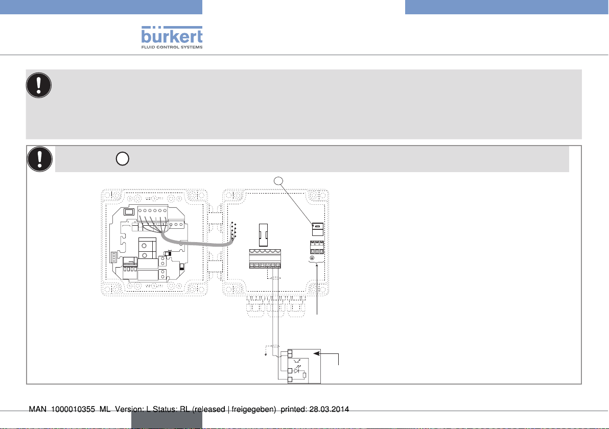
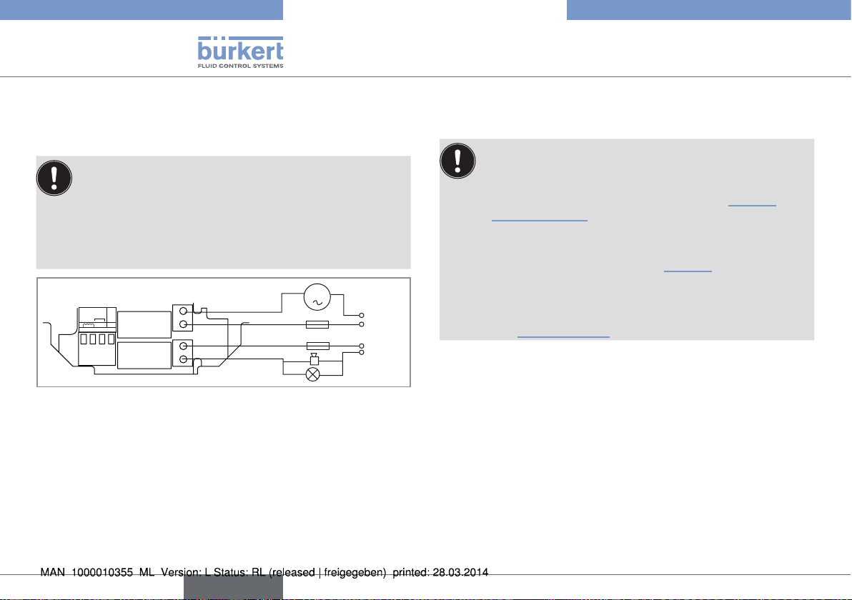
7.4.9 Wiring the relay outputs DO2 and
DO3 of the panel or a wall-mounted
version
Insert▶the▶supplied▶stopper▶gaskets▶into▶the▶unused▶cable▶
glands▶to▶ensure▶the▶tightness▶of▶the▶device.
•▶ Unscrew▶the▶unused▶cable▶gland.
•▶ Remove▶the▶transparent▶disk.
•▶ Insert▶the▶supplied▶stopper▶gasket.
•▶ Screw▶the▶nut▶of▶the▶cable▶gland.
m
FLOW
SENSOR
PULSE
INPUT
SUPPLY
+-
NC
213PE
NPN/PNP
COIL
DO2
DO3
OFFON
Fig. 24: Wiring of the DO2 and DO3 relay outputs
3 A
3 A
230 V AC
230 V AC
7.4.10 Connecting the flow sensor to the
transmitter
Before▶connecting▶the▶flow▶sensor▶to▶the▶transmitter▶8025▶
UNIVERSAL:
•▶ set▶selector▶"SENSOR▶TYPE"▶depending▶on▶the▶output▶
signal▶providing▶from▶▶the▶flow▶sensor.▶See▶„Fig.▶25“▶and▶
„Tab.▶1“▶page▶29.
•▶ if▶the▶selector▶"SENSOR▶TYPE"▶is▶set▶on▶"NPN/PNP",▶
set▶the▶selector▶"SENSOR▶SUPPLY"▶depending▶on▶the▶
transmitter▶supply▶voltage.▶See▶„Fig.▶26“.
•▶ set▶selector▶"LOAD"▶depending▶on▶the▶type▶of▶signal▶sent▶
out▶by▶the▶flow▶sensor▶and▶on▶the▶load▶wanted▶on▶terminal▶
1▶"PULSE▶INPUT"▶of▶terminal▶block▶"FLOW▶SENSOR".▶
See▶„Tab.▶1“▶page▶29.
28
English
Page 29
Type 8025 UNIVERSAL
SENSOR
Installation and wiring
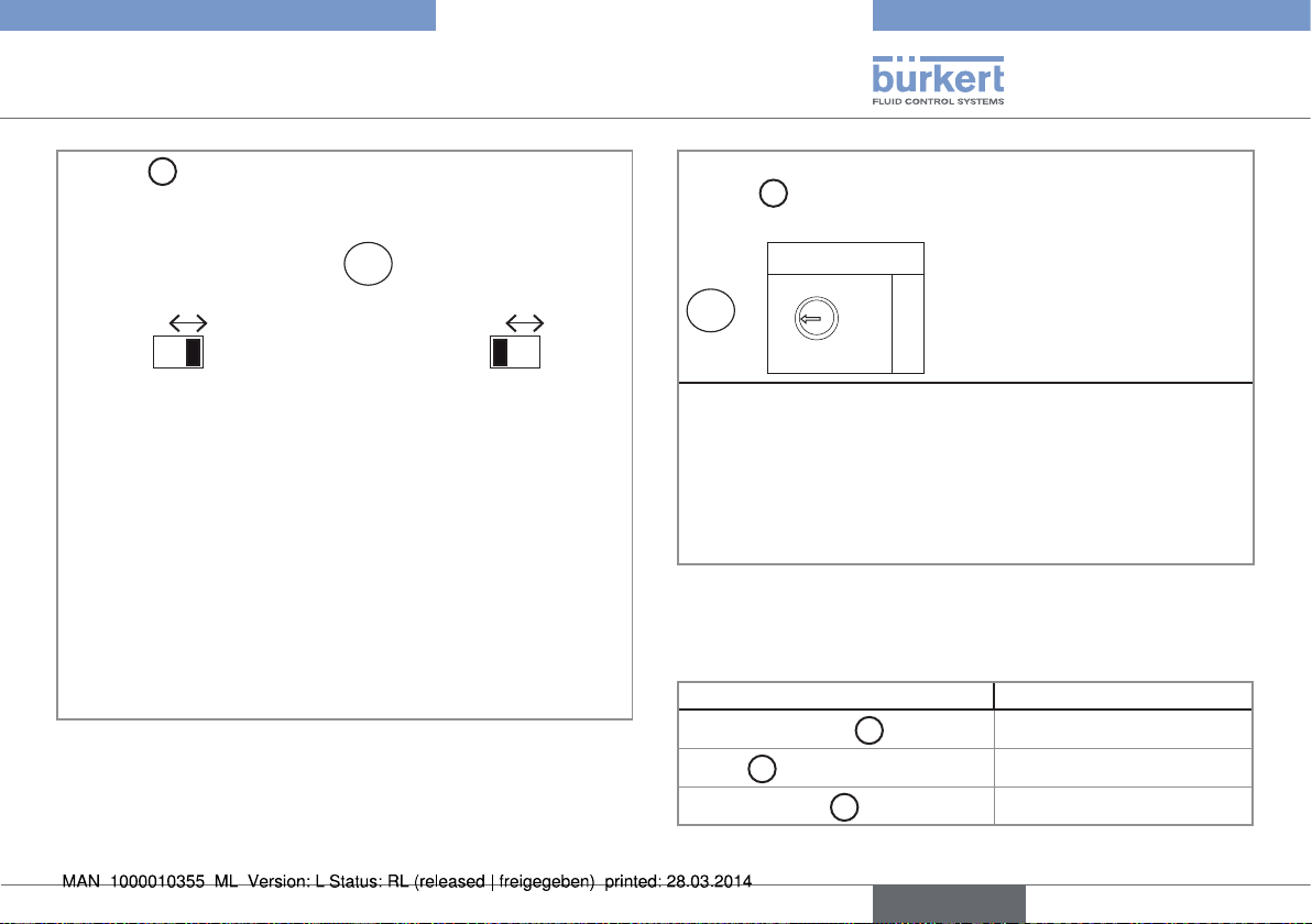
D
Selector▶
▶makes▶it▶possible▶to▶configure▶the▶type▶of▶sig-
nal▶the▶8025▶Universal▶receives▶from▶the▶flow▶sensor.
D
SENSOR TYPE
COIL NPN/PNP
▶→ Set▶the▶selector▶on▶the▶right▶
(default▶position)▶when▶the▶
signal▶from▶the▶flow▶sensor▶
which▶is▶connected▶to▶the▶▶
8025▶Universal▶is▶either:
•▶ a▶pulse▶signal,▶NPN▶or▶PNP
•▶ an▶"on/off"▶signal▶(Reed▶relay▶for▶
example)
•▶ a▶0-5▶V▶DC▶standard▶voltage▶
signal▶(TTL,▶for▶example)
Fig. 25: Using selector "SENSOR TYPE"
SENSOR TYPE
COIL NPN/PNP
▶→ Set▶the▶selector▶on▶the▶
left▶when▶the▶signal▶
from▶the▶flow▶sensor▶
which▶is▶connected▶to▶
the▶▶8025▶Universal▶is▶a▶
sine-wave▶signal▶(coil).
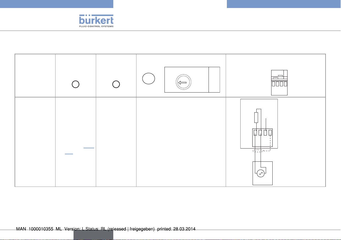
When▶selector▶"SENSOR▶TYPE"▶above▶is▶set▶on▶"NPN/PNP",▶
B
selector▶
the▶flow▶sensor.
▶▶makes▶it▶possible▶to▶configure▶the▶supply▶voltage▶for▶
+5V
B
L+
(L+)-12V
SUPPLY
▶→ If▶the▶8025▶Universal▶is▶energized▶with▶a▶115/230▶V▶AC▶power▶
supply,▶set▶selector▶"SENSOR▶SUPPLY"▶on▶"L+"▶(default▶
position).
▶→ If▶the▶8025▶Universal▶is▶energized▶with▶a▶12-36▶V▶DC▶
power▶supply,▶set▶the▶voltage▶selector▶"SENSOR▶SUPPLY"▶
depending▶on▶the▶voltage▶supply▶needed▶by▶the▶remote▶flow▶
sensor:▶"+5V",▶"L+"▶or▶"(L+)-12V"▶(default▶position).
Fig. 26: Using selector "SENSOR SUPPLY"
Tab. 1: Default positions of selectors "SENSOR SUPPLY",
"LOAD" and "SENSOR TYPE"
Selector Default▶position
SENSOR▶SUPPLY▶(
LOAD▶(
SENSOR▶TYPE▶(D)
C
)
B
)▶
L+
2.2KOhms
NPN/PNP
English
29
Page 30
Type 8025 UNIVERSAL
13
Installation and wiring
Tab. 2: Position of selectors "SENSOR TYPE" and "LOAD" and terminal assignment of terminal block "FLOW SENSOR" depending on the
signal emitted by the flow sensor
Type▶of▶signal▶
emitted▶by▶the▶
flow▶sensor
sine-wave▶(coil)
Selector▶
"SENSOR▶
TYPE"▶
D
)
(
▶→ Set▶the▶
selector▶on▶
"COIL"▶(„Fig.▶
25“)
Selector▶
"SENSOR▶
SUPPLY"▶
(B)▶
▶→ Any▶position.
Selector▶"LOAD"
COIL/PNP
470
C
2.2K
39K
▶→ Set▶selector▶"LOAD"▶on▶"39K":▶
the▶input▶impedance▶on▶terminals▶
1▶and▶2▶of▶terminal▶block▶"FLOW▶
SENSOR"▶will▶then▶be▶39▶kW
LOAD
Terminal▶assignment▶of▶terminal▶block▶
"FLOW▶SENSOR"
SUPPLY
INPUT
+-
NPN/PNP
PULSE
NC
COIL
2
FLOW
SENSOR
PE
8025
39 kΩ
NC
213PE
Flow▶sensor
30
English
Page 31

Type 8025 UNIVERSAL
13
Installation and wiring
Type▶of▶signal▶
emitted▶by▶the▶
flow▶sensor
pulse,▶PNP
Selector▶
"SENSOR▶
TYPE"▶
D
)
(
▶→ Set▶the▶
selector▶on▶
"NPN/PNP"▶
(„Fig.▶25“)
Selector▶
"SENSOR▶
SUPPLY"▶
(B)▶
▶→ Set▶the▶
selector▶as▶
shown▶in▶
„Fig.▶26“.
Selector▶"LOAD"
COIL/PNP
470
C
2.2K
39K
▶→ Set▶selector▶"LOAD"▶on▶"39K":▶
the▶input▶impedance▶on▶terminals▶
1▶and▶2▶of▶terminal▶block▶"FLOW▶
SENSOR"▶will▶then▶be▶39▶kW
LOAD
Terminal▶assignment▶of▶terminal▶block▶
"FLOW▶SENSOR"
SUPPLY
INPUT
+-
NPN/PNP
PULSE
NC
COIL
2
FLOW
SENSOR
PE
8025
39 kΩ
213PE
Flow▶sensor
English
31
Page 32

Type 8025 UNIVERSAL
13
Installation and wiring
Type▶of▶signal▶
emitted▶by▶the▶
flow▶sensor
0-5▶V▶DC▶
standard▶voltage▶
signal▶(TTL,▶for▶
example)
Selector▶
"SENSOR▶
TYPE"▶
D
)
(
▶→ Set▶the▶
selector▶on▶
"NPN/PNP"▶
(„Fig.▶25“)
Selector▶
"SENSOR▶
SUPPLY"▶
(B)▶
▶→ Set▶the▶
selector▶as▶
shown▶in▶
„Fig.▶26“.
Selector▶"LOAD"
COIL/PNP
470
C
2.2K
39K
▶→ Set▶selector▶"LOAD"▶on▶"39K":▶
the▶input▶impedance▶on▶terminals▶
1▶and▶2▶of▶terminal▶block▶"FLOW▶
SENSOR"▶will▶then▶be▶39▶kW
LOAD
Terminal▶assignment▶of▶terminal▶block▶
"FLOW▶SENSOR"
SUPPLY
INPUT
+-
NPN/PNP
PULSE
NC
COIL
2
FLOW
SENSOR
PE
8025
39 kΩ
213PE
Flow▶sensor
32
English
Page 33

Type 8025 UNIVERSAL
13
8025
Installation and wiring
Type▶of▶signal▶
emitted▶by▶the▶
flow▶sensor
pulse,▶NPN
Selector▶
"SENSOR▶
TYPE"▶
D
)
(
▶→ Set▶the▶
selector▶on▶
"NPN/PNP"▶
(„Fig.▶25“)
Selector▶
"SENSOR▶
SUPPLY"▶
(B)▶
▶→ Set▶the▶
selector▶as▶
shown▶in▶
„Fig.▶26“.
Selector▶"LOAD"
COIL/PNP
470
C
2.2K
39K
LOAD
▶→ Set▶selector▶"LOAD":
•▶ either▶on▶"2.2k":▶the▶load▶resistance▶
R▶is▶then▶2,2▶kW
•▶ either▶on▶"470":▶the▶load▶resistance▶
R▶is▶then▶470▶W
Terminal▶assignment▶of▶terminal▶block▶
"FLOW▶SENSOR"
SUPPLY
INPUT
+-
NPN/PNP
PULSE
NC
COIL
2
FLOW
SENSOR
PE
+3 V
R
213PE
Flow▶sensor
English
33
Page 34

Type 8025 UNIVERSAL
13
Installation and wiring
Type▶of▶signal▶
emitted▶by▶the▶
flow▶sensor
"on/off"▶signal▶
(Reed▶relay▶for▶
example)
Selector▶
"SENSOR▶
TYPE"▶
D
)
(
▶→ Set▶the▶
selector▶on▶
"NPN/PNP"▶
(„Fig.▶25“)
Selector▶
"SENSOR▶
SUPPLY"▶
(B)▶
▶→ Set▶the▶
selector▶as▶
shown▶in▶
„Fig.▶26“.
Selector▶"LOAD"
COIL/PNP
470
C
2.2K
39K
LOAD
▶→ Set▶selector▶"LOAD":
•▶ either▶on▶"2.2k":▶the▶load▶resistance▶
R▶is▶then▶2,2▶kW
•▶ either▶on▶"470":▶the▶load▶resistance▶
R▶is▶then▶470▶W
Terminal▶assignment▶of▶terminal▶block▶
"FLOW▶SENSOR"
SUPPLY
INPUT
+-
NPN/PNP
PULSE
NC
COIL
2
FLOW
SENSOR
PE
8025
+3 V
R
213PE
...
Flow▶sensor
34
English
Page 35

Type 8025 UNIVERSAL
Adjustment and commissioning
8 ADJUSTMENT AND
COMMISSIONING
8.1 Safety instructions
Warning
Risk of injury due to nonconforming operating.
Nonconforming▶operating▶could▶lead▶to▶injuries▶and▶damage▶the▶
device▶and▶its▶surroundings.
▶▶ The▶operators▶in▶charge▶of▶operating▶must▶have▶read▶and▶under-
stood▶the▶contents▶of▶this▶manual.
▶▶ In▶particular,▶observe▶the▶safety▶recommendations▶and▶intended▶use.
▶▶ The▶device/installation▶must▶only▶be▶operated▶by▶suitably▶trained▶
staff.
Warning
Danger due to nonconforming commissioning.
Nonconforming▶commissioning▶could▶lead▶to▶injuries▶and▶damage▶
the▶device▶and▶its▶surroundings.▶
▶▶ Before▶commissioning,▶make▶sure▶that▶the▶staff▶in▶charge▶have▶read▶
and▶fully▶understood▶the▶contents▶of▶the▶operating▶instructions.
▶▶ In▶particular,▶observe▶the▶safety▶recommendations▶and▶intended▶use.
▶▶ The▶device▶/▶the▶installation▶must▶only▶be▶commissioned▶by▶suit-
ably▶trained▶staff.
▶▶ Before▶commissioning▶the▶device,▶enter▶the▶K▶factor▶of▶the▶fitting▶
used.▶See▶chap.▶„8.7▶Entering▶the▶K▶factor▶of▶the▶fitting▶used“.
8.2 Operating levels of the device
The▶device▶has▶two▶operating▶levels:▶the▶Process▶level▶and▶the▶Configuration▶level.
Tab. 3: Default settings of the device
Function Default▶value
LANGUAGE English
UNIT▶of▶the▶flow▶rate l/min.
UNIT▶of▶the▶totalizers litre
OUTPUT▶AO1 4mA=▶0.000
20mA=▶0.000
ERR.▶22mA▶disabled
OUTPUT▶DO1 pulse
PU=▶0.00▶litre
OUTPUTS▶DO2▶and▶
DO3
K▶FACTOR
FILTER
CUT-OFF
BACKLIGHT level▶9,▶activated▶for▶30s
FLOW-WARNING W-▶=▶W+▶=▶0.000
VOLUME-WARNING 000000
Hysteresis,▶not▶inverted
2-▶=▶3-▶=▶0.000
2+▶=▶3+▶=▶0.000
time▶delays▶2▶and▶3▶=▶0
1
2,▶fast
0.000
English
35
Page 36

Type 8025 UNIVERSAL
Adjustment and commissioning
Process▶level
12.6 L/MiN
16.45 MA
0......9
87654 L
231 L.
+
0......9
>▶2▶s
To▶reset▶the▶daily▶totalizer▶(identified▶by▶a▶dot▶after▶the▶volume▶
units).
>▶5▶s
Parameters▶menu
ENTER
0......9
>▶5▶s
0......9
LANGUAGE
UNit
K-FACtOR
OUtPUt
FiLtER
tOtAL
CUt-OFF
BACKLit
Configuration▶level
ENTER
0......9
>▶2▶s
Test▶Menu
CAL AO1
FREQUENC.
FLOw
wARNiNG
END
Information▶menu▶
MEAS. OVF
DiSP. OVF
AO1 LOSt
0......9
END
ENTER
1)
1)
▶Accessible▶when▶the▶device▶status▶LED▶is▶orange▶or▶red.
36
English
END
SAVE N/Y
Process▶level
Page 37

Type 8025 UNIVERSAL
Adjustment and commissioning
8.3 Description of the navigation keys and the status LEDs
•▶ Scrolling▶up▶the▶
parameters
•▶ Incrementing▶the▶figure▶
selected
Device▶status▶LED:▶see▶following▶table.
•▶ Selecting▶the▶displayed▶parameter
•▶ Confirming▶the▶settings
Status▶LED▶of▶relay▶DO3▶(LED▶ON▶=▶
contact▶closed)
Status▶LED▶of▶relay▶DO2▶(LED▶ON▶=▶
contact▶closed)
•▶ Reading▶the▶messages▶
•▶ Scrolling▶through▶the▶parameters
•▶ Selecting▶the▶figure▶on▶the▶left
English
37
Page 38

Type 8025 UNIVERSAL
Adjustment and commissioning
Device status LED Status of the device
Green The▶device▶operates▶correctly.
Orange A▶warning▶message▶is▶generated.
▶→ Press▶the▶ ▶key▶for▶2▶seconds▶in▶the▶Process▶level▶to▶access▶the▶message.▶See▶the▶complete▶
operating▶instructions▶for▶the▶meaning.
Furthermore,▶a▶relay▶output▶(DO2▶or▶DO3)▶or▶the▶transistor▶output▶DO1▶switches▶if▶it▶is▶configured▶in▶
the▶"WARNING"▶mode▶(see▶the▶complete▶operating▶instructions▶)
Red An▶error▶message▶has▶been▶generated▶and▶the▶current▶output▶sends▶out▶a▶22▶mA▶current▶(if▶
parameter▶"ERR.▶22mA"▶is▶set▶to▶"ENABLED".▶See▶the▶complete▶operating▶instructions.
▶→ Press▶the▶ ▶key▶for▶2▶seconds▶in▶the▶Process▶level▶to▶access▶the▶message.▶See▶the▶complete▶
operating▶instructions▶for▶the▶meaning.
Blinking,▶whatever▶the▶colour A▶check▶for▶the▶correct▶behaviour▶of▶the▶outputs▶is▶running▶(see▶the▶complete▶operating▶instructions).
8.4 Using the navigation keys
You want to... Press...
move▶between▶parameters▶within▶a▶level▶or▶a▶menu.
▶to▶go▶to▶the▶next▶parameter.▶
•▶
access▶the▶Parameters▶menu.
38
English
▶to▶go▶to▶the▶previous▶parameter.
•▶
0......9
ENTER
▶+▶ ▶simultaneously▶for▶5▶s,▶in▶the▶Process▶level
Page 39

Type 8025 UNIVERSAL
Adjustment and commissioning
You want to... Press...
access▶the▶Test▶menu.
0......9
▶+▶ ▶+▶
access▶the▶Information▶menu.
▶for▶2▶s,▶in▶the▶Process▶level,▶when▶the▶device▶status▶LED▶is▶orange▶or▶red.
ENTER
▶simultaneously▶for▶5▶s,▶in▶the▶Process▶level
reset▶the▶daily▶totalizer.
select▶the▶displayed▶parameter.
confirm▶the▶displayed▶value.
modify▶a▶numerical▶value.
0......9
▶+▶ ▶simultaneously▶for▶2▶s,▶when▶the▶daily▶totalizer▶is▶displayed▶in▶the▶
Process▶level
ENTER
ENTER
▶to▶increase▶the▶blinking▶digit.
•▶
0......9
▶to▶select▶the▶digit▶at▶the▶left▶of▶the▶blinking▶digit.
•▶
0......9
▶+▶ ▶to▶move▶the▶decimal▶point.
•▶
English
39
Page 40

8.5 Details of the Process level
This▶level▶is▶active▶by▶default▶when▶the▶device▶is▶energized.
12.6 L/MiN
0......9
16.45 MA
or
Value▶of▶the▶measured▶flow▶rate,▶displayed▶in▶the▶unit▶chosen▶in▶the▶"UNIT"▶parameter▶of▶the▶
Parameters▶menu.
Value▶of▶the▶current▶output,▶proportional▶to▶the▶measured▶flow▶rate.
0 L/MiN.
Type 8025 UNIVERSAL
Adjustment and commissioning
The▶displayed▶flow▶rate▶is▶set▶to▶0▶(a▶dot▶is▶displayed▶after▶the▶flow▶rate▶
units▶when▶the▶function▶CUT-OFF▶is▶active)▶because▶the▶measured▶flow▶
rate▶is▶below▶the▶threshold▶value▶defined▶in▶the▶"CUT-OFF"▶parameter▶
of▶the▶Parameters▶menu.
40
87654 L
231 L.
Value▶of▶the▶main▶totalizer,▶volume▶of▶fluid▶counted▶by▶the▶device▶since▶the▶last▶reset.
Value▶of▶the▶daily▶totalizer▶(identified▶by▶a▶dot▶after▶the▶volume▶units),▶volume▶of▶fluid▶counted▶by▶
the▶device▶since▶the▶last▶reset.
0......9
+
>▶2▶s
Resetting▶the▶daily▶totalizer.
English
Page 41

Type 8025 UNIVERSAL
Adjustment and commissioning
8.6 Details of the Parameters menu
0......9
LANGUAGE
UNit
K-FACtOR
OUtPUt
FiLtER
tOtAL
CUt-OFF
BACKLit
END
Choosing▶the▶display▶language.
Choosing▶the▶flow▶rate▶unit,▶the▶number▶of▶decimals▶and▶the▶unit▶the▶totalizers▶are▶displayed▶in.
Entering▶the▶K▶factor▶of▶the▶fitting▶used▶or▶having▶it▶defined▶through▶a▶Teach-In▶procedure.▶
Parameterizing▶the▶4-20▶mA▶current▶output▶(AO1)▶and▶configuring▶the▶transistor▶output▶(DO1)▶
and,▶if▶the▶device▶is▶equipped▶with,▶the▶2▶relay▶outputs▶(DO2▶and▶DO3).
Choosing▶the▶filter▶level▶of▶the▶measured▶flow▶rate,▶on▶the▶displayed▶flow▶rate▶and▶the▶AO1▶
current▶output.
Resetting▶both▶totalizers.
Entering▶the▶measured▶flow▶rate▶value▶below▶which▶the▶device▶sets▶the▶measured▶flow▶rate▶to▶0▶
with▶effect▶on▶the▶display,▶the▶outputs▶and▶the▶totalizers.
Setting▶the▶brightness▶of▶the▶display▶and▶how▶long▶it▶stays▶ON,▶or▶deactivating▶the▶backlight.
SAVE N/Y
Saving▶the▶changes▶made▶within▶the▶Parameters▶menu▶or▶
not.▶If▶the▶changes▶are▶saved,▶the▶device▶operates▶with▶
the▶new▶settings.
12.6 L/MiN
Process▶level
English
41
Page 42

Type 8025 UNIVERSAL
Adjustment and commissioning
8.7 Entering the K factor of the fitting used
The▶device▶determines▶the▶flow▶rate▶in▶the▶pipe▶using▶the▶fitting▶K▶factor.
The▶K▶factor▶of▶the▶fitting▶used▶can▶be▶entered▶here.▶The▶device▶may▶also▶determine▶the▶K▶factor▶using▶a▶Teach-In▶procedure:▶See▶the▶com-
plete▶operating▶instructions.
The▶device▶will▶use▶the▶new▶K▶factor▶as▶soon▶as▶"SAVE▶YES"▶is▶confirmed▶when▶leaving▶the▶Parameters▶menu.
The▶K▶factor▶of▶the▶fitting▶used▶is▶in▶the▶operating▶instructions▶of▶the▶fitting.
The▶operating▶instructions▶of▶the▶Bürkert▶fittings▶can▶be▶found▶on▶the▶CD▶delivered▶with▶the▶device▶or▶on▶the▶internet▶at▶
www.burkert.com.
K-FACtOR K=10.000
The▶display▶shows▶the▶K▶factor▶of▶the▶
fitting,▶last▶entered▶or▶determined▶using▶
a▶Teach-In▶procedure.
K=2.8500
▶→ Enter▶the▶K▶factor▶(value▶between▶0.01▶and▶
99999.9)▶of▶the▶fitting▶used.
▶→ Confirm▶the▶displayed▶value.
▶→ Edit▶the▶parameter.
OUtPUt VALiD N/Y
REtURN
Is▶only▶displayed▶if▶the▶K▶factor▶has▶been▶changed.
▶→ Confirm▶the▶entered▶K▶factor▶or▶not.
Fig. 27: Entering the K factor of the fitting used
42
English
Page 43

Type 8025 UNIVERSAL
Adjustment and commissioning
8.8 Details of the Test menu
0......9
CAL AO1
FREQUENC.
FLOw
wARNiNG
END
Adjusting▶the▶4-20▶mA▶output.
Reading▶the▶rotational▶frequency▶of▶the▶paddle▶wheel.
Simulating▶a▶flow▶rate▶to▶check▶the▶correct▶operating▶of▶the▶outputs.
FLOw-w.
0......9
VOLUME-w.
Setting▶the▶flow▶rate▶threshold▶values▶for▶which▶a▶warning▶message▶is▶
generated.
Setting▶a▶threshold▶value▶of▶the▶daily▶totalizer,▶for▶which▶a▶warning▶message▶
is▶generated.
REtURN
SAVE N/Y
Saving▶the▶changes▶made▶within▶the▶Test▶menu▶or▶not.▶If▶
the▶changes▶are▶saved,▶the▶device▶operates▶with▶the▶new▶
settings.
12.6 L/MiN
Process▶level
English
43
Page 44

Type 8025 UNIVERSAL
Packaging, Transport
9 PACKAGING, TRANSPORT
note▶
Damage due to transport
Transport▶may▶damage▶an▶insufficiently▶protected▶device.
▶▶ Transport▶the▶device▶in▶shock-resistant▶packaging▶and▶away▶
from▶humidity▶and▶dirt.
▶▶ Do▶not▶expose▶the▶device▶to▶temperatures▶that▶may▶exceed▶the▶
admissible▶storage▶temperature▶range.
▶▶ Protect▶the▶electrical▶interfaces▶using▶protective▶plugs.▶
1. STORAGE
note▶
Poor storage can damage the device.
▶▶ Store▶the▶device▶in▶a▶dry▶place▶away▶from▶dust.
▶▶ Storage▶temperature▶of▶the▶device:▶-10▶to▶+60▶°C.
10 DISPOSAL OF THE PRODUCT
▶→
Dispose▶of▶the▶device▶and▶its▶packaging▶in▶an▶environmentallyfriendly▶way.
note
Comply▶with▶the▶national▶and/or▶local▶regulations▶which▶
concern▶the▶area▶of▶waste▶disposal.
44
English
Page 45

Typ 8025 UNIVERSAL
Inhaltsverzeichnis
1 ÜBER DEN QUICKSTART ........................................................................2
2 BESTIMMUNGSGEMÄSSE VERWENDUNG...................................3
3 GRUNDLEGENDE SICHERHEITSHINWEISE .................................3
4 ALLGEMEINE HINWEISE ..........................................................................4
5 BESCHREIBUNG ..........................................................................................5
6 TECHNISCHE DATEN ................................................................................6
7 INSTALLATION, VERKABELUNG ...........................................................10
8 BEDIENUNG, INBETRIEBNAHME ....................................................................... 34
9 VERPACKUNG, TRANSPORT .............................................................. 44
10 LAGERUNG ...................................................................................................44
11 ENTSORGUNG DES GERÄTES ......................................................... 44
deutsch
1
Page 46

Typ 8025 UNIVERSAL
Warnt vor Sachschäden!
Über den Quickstart
1 ÜBER DEN QUICKSTART
Der▶Quickstart▶beschreibt▶den▶gesamten▶Lebenszyklus▶des▶Gerätes.▶
Bewahren▶Sie▶ diese▶ Anleitung▶ so▶ auf,▶ dass▶ sie▶ für▶ jeden▶ Benutzer▶
zugänglich▶ist▶und▶jedem▶neuen▶Eigentümer▶des▶Gerätes▶wieder▶zur▶
Verfügung▶steht.
Wichtige Informationen zur Sicherheit!
Lesen▶Sie▶den▶Quickstart▶sorgfältig▶durch.▶Beachten▶Sie▶vor▶allem▶
die▶Kapitel▶Grundlegende▶Sicherheitshinweise▶und▶Bestimmungsgemäße▶Verwendung.
▶▶ Der▶Quickstart▶muss▶gelesen▶und▶verstanden▶werden.
Der▶Quickstart▶erläutert▶beispielhaft▶die▶Montage▶und▶Inbetriebnahme▶des▶Gerätes.
Die▶ausführliche▶Beschreibung▶des▶Gerätes▶finden▶Sie▶in▶der▶entsprechenden▶Bedienungsanleitung▶auf▶der▶mitgelieferten▶CD.
1.1 Darstellungsmittel
GefaHR!
Warnt vor einer unmittelbaren Gefahr!
▶▶ Bei▶Nichteinhaltung▶sind▶Tod▶oder▶schwere▶Verletzungen▶die▶
Folge.
waRnunG!
Warnt vor einer möglicherweise gefährlichen Situation!
▶▶ Bei▶Nichteinhaltung▶drohen▶schwere▶Verletzungen▶oder▶Tod.
VORSICHT!
Warnt vor einer möglichen Gefährdung!
▶▶ Nichtbeachtung▶kann▶mittelschwere▶oder▶leichte▶Verletzungen▶
zur▶Folge▶haben.▶
HInweIS!
▶▶ Bei▶Nichtbeachtung▶kann▶das▶Gerät▶oder▶die▶Anlage▶beschädigt▶
werden.
bezeichnet▶wichtige▶Zusatzinformationen,▶Tipps▶und▶
Empfehlungen.
verweist▶auf▶Informationen▶in▶dieser▶Bedienungsanleitung▶
oder▶in▶anderen▶Dokumentationen.
▶→ markiert▶einen▶Arbeitsschritt,▶den▶Sie▶ausführen▶müssen.
1.2 Begriffsdefinition "Gerät"
Der▶in▶dieser▶Anleitung▶verwendete▶Begriff▶"Gerät"▶steht▶immer▶für▶
den▶Transmitter▶Typ▶8025▶Universal▶mit▶einer▶Serien-Nummer▶größer▶
oder▶gleich▶20▶000.
2
deutsch
Page 47

Typ 8025 UNIVERSAL
Bestimmungsgemässe Verwendung
2 BESTIMMUNGSGEMÄSSE
VERWENDUNG
Bei nicht bestimmungsgemäßem Einsatz dieses Gerätes
können Gefahren für Personen, Anlagen in der Umgebung
und die Umwelt entstehen.
▶▶ Der▶Transmitter▶Typ▶8025▶Universal▶ist▶für▶die▶Bearbeitung▶eines▶
Frequenzsignals,▶das▶er▶vom▶angeschlossenen▶DurchflussSensor▶aufnimmt,▶bestimmt.
▶▶ Schützen▶Sie▶das▶Gerät▶vor▶elektromagnetischen▶Stö-
rungen,▶U.V.-Bestrahlung▶und▶bei▶Außenanwendung▶vor▶
Witterungseinflüssen.
▶▶ Für▶den▶Einsatz▶sind▶die▶in▶den▶Vertragsdokumenten▶und▶der▶
Bedienungsanleitung▶spezifizierten▶zulässigen▶Daten,▶Betriebs-▶
und▶Einsatzbedingungen▶zu▶beachten.
▶▶ Zum▶sicheren▶und▶problemlosen▶Einsatz▶des▶Gerätes▶müssen▶
Transport,▶Lagerung▶und▶Installation▶ordnungsgemäß▶erfolgen,▶
außerdem▶müssen▶Betrieb▶und▶Wartung▶sorgfältig▶durchgeführt▶
werden.
▶▶ Achten▶Sie▶immer▶darauf,▶dieses▶Gerät▶auf▶ordnungsgemäße▶
Weise▶zu▶verwenden.
▶▶ Beachten▶Sie▶bei▶der▶Ausfuhr▶des▶Gerätes▶gegebenenfalls▶beste-
hende▶Beschränkungen.
3 GRUNDLEGENDE
SICHERHEITSHINWEISE
Diese▶Sicherheitshinweise▶berücksichtigen▶keine▶
•▶ Zufälligkeiten▶und▶Ereignisse,▶die▶bei▶Montage,▶Betrieb▶und▶
Wartung▶der▶Geräte▶auftreten▶können.
•▶ Ortsbezogenen▶Sicherheitsbestimmungen,▶für▶deren▶Einhaltung,▶auch▶
in▶Bezug▶auf▶das▶Installations-▶und▶Wartungspersonal,▶der▶Betreiber▶
verantwortlich▶ist.
Gefahr durch elektrische Spannung!
▶▶ Schalten▶Sie▶vor▶Beginn▶der▶Arbeiten▶in▶jedem▶Fall▶alle▶existieren-
den▶am▶ Gerät▶angeschlossenen▶ Spannungs-Versorgungen▶ab,▶
und▶sichern▶Sie▶diese▶vor▶unbeabsichtigtem▶Wiedereinschalten!
▶▶ Beachten▶Sie▶geltende▶Unfallverhütungs-▶und▶Sicherheitsbestim-
mungen▶für▶elektrische▶Geräte!
Allgemeine Gefahrensituationen.
Zum▶Schutz▶vor▶Verletzungen▶ist▶zu▶beachten
▶▶ Dieses▶Gerät▶nicht▶in▶explosionsgefährdeten▶Bereichen▶
einsetzen.
▶▶ Dieses▶Gerät▶nicht▶in▶einer▶Umgebung▶verwenden,▶die▶mit▶den▶
Materialien,▶aus▶denen▶es▶besteht,▶inkompatibel▶ist.
▶▶ Belasten▶Sie▶das▶Gerät▶nicht▶mechanisch▶(z.▶B.▶durch▶Ablage▶
von▶Gegenständen▶oder▶als▶Trittstufe).
deutsch
3
Page 48

Typ 8025 UNIVERSAL
Allgemeine Hinweise
4 ALLGEMEINE HINWEISE
Allgemeine Gefahrensituationen.
Zum▶Schutz▶vor▶Verletzungen▶ist▶zu▶beachten
▶▶ Nehmen▶Sie▶keine▶äußerlichen▶oder▶innerlichen▶Veränderungen▶
am▶Gerät▶vor.
▶▶ Dass▶die▶Anlage▶nicht▶unbeabsichtigt▶betätigt▶werden▶kann.
▶▶ Installations-▶und▶Instandhaltungsarbeiten▶dürfen▶nur▶von▶autorisier-
tem▶Fachpersonal▶mit▶geeignetem▶Werkzeug▶ausgeführt▶werden.
▶▶ Nach▶einer▶Unterbrechung▶der▶elektrischen▶Versorgung▶ist▶ein▶
definierter▶oder▶kontrollierter▶Wiederanlauf▶des▶Prozesses▶zu▶
gewährleisten.
▶▶ Betreiben▶Sie▶das▶Gerät▶nur▶in▶einwandfreiem▶Zustand▶und▶
unter▶Beachtung▶der▶Bedienungsanleitung.
▶▶ Bei▶der▶Einsatzplanung▶und▶dem▶Betrieb▶des▶Gerätes▶die▶allge-
meinen▶Regeln▶der▶Technik▶einhalten.
HInweIS!▶
Elektrostatisch gefährdete Bauelemente / Baugruppen!
▶▶ Das▶Gerät▶enthält▶elektronische▶Bauelemente,▶die▶gegen▶
elektrostatische▶Entladung▶empfindlich▶reagieren.▶Berührung▶
mit▶elektrostatisch▶aufgeladenen▶Personen▶oder▶Gegenständen▶
gefährdet▶diese▶Bauelemente.▶Im▶schlimmsten▶Fall▶werden▶sie▶
sofort▶zerstört▶oder▶fallen▶nach▶der▶Inbetriebnahme▶aus.
▶▶ Beachten▶Sie▶die▶Anforderungen▶nach▶EN▶61340▶-5-1▶und▶5-2,▶
um▶die▶Möglichkeit▶eines▶Schadens▶durch▶schlagartige▶elektro-
statische▶Entladung▶zu▶minimieren▶bzw.▶zu▶vermeiden!
▶▶ Achten▶Sie▶ebenso▶darauf,▶dass▶Sie▶elektronische▶Bauelemente▶
nicht▶bei▶anliegender▶Versorgungsspannung▶berühren!▶
4.1 Herstelleradresse und
internationale Kontaktadressen
Sie▶können▶mit▶dem▶Hersteller▶des▶Gerätes▶unter▶folgender▶Adresse▶
Kontakt▶aufnehmen:
Bürkert▶SAS
Rue▶du▶Giessen
BP▶21
F-67220▶TRIEMBACH-AU-VAL
oder▶wenden▶Sie▶sich▶an▶Ihr▶lokal▶zuständiges▶Vertriebsbüro▶von▶
Bürkert.
Die▶internationalen▶Kontaktadressen▶finden▶Sie▶im▶Internet▶unter:▶
www.burkert.com
4.2 Gewährleistung
Voraussetzung▶für▶die▶Gewährleistung▶ist▶der▶bestimmungsgemäße▶
Gebrauch▶des▶Gerätes▶unter▶Beachtung▶der▶in▶der▶vorliegenden▶
Bedienungsanleitung▶spezifizierten▶Einsatzbedingungen.
4.3 Informationen im Internet
Bedienungsanleitungen▶und▶Datenblätter▶zum▶Typ▶8025▶finden▶Sie▶
im▶Internet▶unter:▶www.buerkert.de
4
deutsch
Page 49

Typ 8025 UNIVERSAL
1
35
4
2
Beschreibung
5 BESCHREIBUNG
5.1 Vorgesehener Einsatzbereich
Der▶Transmitter▶Typ▶8025▶Universal▶kann▶an▶einen▶abgesetzten▶Durchfluss-Sensor,▶der▶ein▶Frequenzsignal▶ausgibt,▶angeschlossen▶werden.▶
Die▶vorgeschriebenen▶ technischen▶Daten▶ des▶angeschlossenen▶
Durchfluss-Sensors▶sind▶im▶Kapitel▶„6▶Technische▶Daten“▶beschrieben.
Wenn▶das▶ Gerät▶ an▶ einem▶ Durchfluss-Sensor▶ angeschlossen▶ ist,▶
ermöglichen▶die▶ einstellbaren▶ Transistor-▶und,▶ bei▶einigen▶ Ausführungen,▶die▶beiden▶Relaisausgänge▶dem▶Gerät,▶ein▶Magnetventil▶zu▶
schalten,▶einen▶ Alarm▶ zu▶ aktivieren▶ oder▶ eine▶ dem▶ Durchfluss▶ proportionale▶Frequenz▶ zu▶ erzeugen,▶ und▶ der▶4-20▶ mA▶ Stromausgang▶
ermöglicht▶einen▶Regelkreise▶aufzubauen.
5.2 Beschreibung des Typenschilds
▶
LFLOW 8025 PANEL SUPPLY: 12-36V= 210 mA
DO1: 5-36V= 100mA AO1:4-20mA
DO2&3: 2xRelay 30 and 42V peak or 60V... max. IP20
S/N 20 000
Made in France
00564417 W46MA
10
9
781112
6
1.▶ Messgröße
2.▶ Typ▶des▶Gerätes,▶Gehäuse
3.▶ Daten▶des▶Transistorausgangs▶DO1
4.▶ Daten▶des▶Analogausgangs▶AO1▶
5.▶ Betriebsspannung▶und▶max.▶Stromverbrauch▶
6.▶ Schutzart▶des▶Gerätes
7.▶ Herstellungscode▶Konformitäts-Logos
8.▶ Warnung:▶Bevor▶das▶Gerät▶benutzt▶wird,▶die▶in▶der▶
Bedienungsanleitung▶beschriebenen▶technischen▶Daten▶▶
berücksichtigen.
9.▶ Daten▶der▶Relais-Ausgänge▶DO2▶und▶DO3
10.▶Seriennummer
11.▶Bestellnummer
Bild 1: Typenschild des Transmitters 8025 Universal (Beispiel)
deutsch
5
Page 50

Typ 8025 UNIVERSAL
Technische Daten
6 TECHNISCHE DATEN
6.1 Betriebsbedingungen
Temperaturbereich -10▶bis▶+60▶°C
Luftfeuchtigkeit <▶80▶%,▶nicht▶kondensierend
Höhe▶über▶Meeresspiegel 2000▶m.▶max.
Einbaukategorie Kategorie▶I▶nach▶UL▶61010-1
Verschmutzungsgrad Grad▶2▶nach▶EN▶61010-1
Schutzart
•▶ Wandmontage-Ausführung▶
▶
▶
▶
▶
•▶ Schaltschrank-Ausführung
6.2 Einhaltung von Normen und
Richtlinien
Durch▶folgende▶Normen▶wird▶die▶Konformität▶mit▶den▶EG-Richtlinien▶
erfüllt:
•▶ EMV:▶EN▶61000-6-2,▶EN▶61000-6-3
nach▶EN▶60529
•▶ IP65,▶mit▶angeschlossenem▶Gerät,▶
festgeschraubten▶Kabelverschraubungen,▶festgeschraubtem▶Deckel▶
und▶mit▶einem▶Drehmoment▶von▶
1.5▶Nm▶am▶Gehäuse▶festgeschraubten▶Zwischenstutzen▶der▶
Kabelverschraubungen.
•▶ außerhalb▶des▶Schaltschranks▶
IP65,▶innerhalb▶des▶Schranks▶IP20
•▶ Niederspannungsrichtlinie:▶EN▶61010-1
•▶ Prüfung▶Umgebungseinfluss:
▶- Vibration:▶EN▶60068-2-6,
▶- Schock:▶EN▶60068-2-27.
Die▶UL-Geräte▶mit▶variablem▶Schlüssel▶PU01▶entsprechen▶den▶folgenden▶Normen:
•▶ UL▶61010-1
•▶ CAN/CSA-C22.2▶n°▶61010-1
6.3 Mechanische Daten
Teil Werkstoff
Gehäuse▶und▶Deckel,▶
Wandmontage-Ausführung
Kabelverschraubungen,▶
Wandmontage-Ausführung
Schaltschrank-Gehäuse PC
Folie Polyester
4▶Schrauben Edelstahl
Kabelschellen PA
ABS
PA
6
deutsch
Page 51

Typ 8025 UNIVERSAL
Technische Daten
88
76
FLOW
88
ENTER
0....9
40
25
Bild 2: Abmessungen des Transmitters 8025 Universal,
Schaltschrank-Ausführung [mm]
126
FLOW
23
90
31.50
23
0....9
ENTER
Bild 3: Abmessungen des Transmitters 8025 Universal,
Wandmontage-Ausführung [mm]
120
6.4 Elektrische Daten
12-36▶V▶DC-VersorgungsSpannung
Spannungsquelle▶(nicht▶
mitgeliefert)
115/230▶V▶AC-Versorgungs-
143
Spannung
•▶ Frequenz
•▶ Gelieferte▶Spannung
•▶ Strom
•▶ Integrierter▶Schutz
•▶ Leistung
•▶ Gefiltert▶und▶geregelt
•▶ Stromkreis▶mit▶SicherheitsKleinspannung▶und▶nicht▶
gefährlichem▶Energieniveau
•▶ Max.▶Toleranz▶für▶12▶V▶DC:▶
-5▶%▶oder▶+10%
•▶ Max.▶Toleranz▶für▶36▶V▶DC:▶
±10▶%
•▶ Quelle▶mit▶begrenzter▶
Leistung▶gemäß▶Kap.▶9.3▶der▶
Norm▶EN▶61010-1
•▶ oder▶Quelle▶der▶Klasse▶
2▶gemäß▶den▶Normen▶▶
UL▶1310/1585▶und▶
EN▶60950-1
▶
•▶ 50/60▶Hz
•▶ 27▶V▶DC,▶geregelt
•▶ Max.▶250▶mA
•▶ 250▶mA-Zeitsicherung
•▶ 6▶VA
deutsch
7
Page 52

Typ 8025 UNIVERSAL
Technische Daten
Eigenverbrauch▶(ohne▶den▶Verbrauch▶des▶4-20▶mA-Ausgangs)
•▶ Ausführung▶ohne▶Relais,▶
12-36▶V▶DC-Versorgungsspannung
•▶ Ausführung▶mit▶Relais,▶
12-36▶V▶DC-Versorgungsspannung
•▶ Ausführung▶ohne▶Relais,▶
115/230▶V▶AC-Versorgungsspannung
•▶ Ausführung▶mit▶Relais,▶
115/230▶V▶AC-Versorgungsspannung
▶
•▶ 60▶mA▶(bei▶12▶V▶DC)▶und▶
30▶mA▶(bei▶36▶V▶DC)▶
•▶ 90▶mA▶(bei▶12▶V▶DC)▶und▶
45▶mA▶(bei▶36▶V▶DC)▶
•▶ 40▶mA▶
▶
•▶ 55▶mA
Transistorausgang DO1
•▶ Typ ▶
•▶ Funktion▶
•▶ Frequenz▶(f)
•▶ Elektrische▶Daten▶
▶
•▶ Taktverhältnis▶bei▶
0,6▶<▶f▶<▶300▶Hz
•▶ Taktverhältnis▶bei▶
300▶<▶f▶<▶1500▶Hz
•▶ Taktverhältnis▶bei▶
1500▶<▶f▶<▶2200▶Hz
•▶ Schutz
Polarisiert,▶potentialfrei
•▶ NPN▶/▶PNP▶(je▶nach▶
Verkabelung)
•▶ Pulsausgang▶(Grundeinstellung),▶einstellbar
•▶ 0,6-2200▶Hz
•▶ 5-36▶V▶DC,▶100▶mA▶max.,▶
Spannungsabfall▶von▶
2,7▶V▶DC▶bei▶100▶mA
•▶ >▶0,45▶
•▶ >▶0,4▶
•▶ <▶0,4▶
•▶ Galvanisch▶getrennt;▶Schutz▶
gegen▶Überspannung,▶Verpolung▶und▶Kurzschluss
8
deutsch
Page 53

Typ 8025 UNIVERSAL
Technische Daten
Relais-Ausgänge DO2 und
DO3
•▶ Umschaltbetrieb▶
•▶ Elektrische▶Daten▶der▶Last▶
(nicht▶UL-Geräte)
•▶ Elektrische▶Daten▶der▶Last▶
(UL-Geräte)
•▶ Max.▶Schaltvermögen
•▶ Lebensdauer
Stromausgang AO1
•▶ Daten▶
▶
▶
•▶ Schleifenimpedanz▶max.▶bei▶
einem▶mit▶12-36▶V▶DC▶versorgtem▶Gerät▶
•▶ Schleifenimpedanz▶max.▶bei▶
einem▶mit▶115/230▶V▶AC▶
versorgtem▶Gerät
▶
•▶ Hysterese▶(Grundeinstellung),▶
einstellbar,▶stromlos▶geöffnet
•▶ 230▶V▶AC▶/▶3▶A▶oder▶40▶V▶DC▶
/▶3▶A
•▶ max.▶30▶V▶AC▶und▶42▶V▶Spitze▶
oder▶max.▶60▶V▶DC,▶3▶A
•▶ 750▶VA▶(ohmsche▶Last)
•▶ ▶min.▶100000▶Zyklen
•▶ 4-20▶mA,▶Senke▶oder▶Quelle▶
(je▶nach▶Verkabelung),▶
22▶mA▶zur▶Fehlermeldung▶
(aktivierbar)
•▶ 1300W▶bei▶36▶V▶DC,▶1000W▶
bei▶30▶V▶DC,▶750W▶bei▶
24▶V▶DC,▶300W▶bei▶15▶V▶DC,▶
200W▶bei▶12▶V▶DC
•▶ 900W
6.5 Daten des angeschlossenen
Durchfluss-Sensors
Signal▶vom▶abgesetzten▶Sensor
•▶ Typ ▶
▶
▶
•▶ Frequenz
•▶ max.▶Spannung
Eingangsimpedanz
Betriebsspannung durch▶den▶Transmitter▶je▶nach▶Stelle▶des▶
▶
•▶ Pulssignal,▶sinusförmiges▶Signal▶(Empfindlichkeit:▶typisch▶50▶mV▶Spitze-Spitze▶bei▶
250▶Hz),▶On/Off-Signal,▶oder▶genormter▶
0-5▶V▶DC▶Spannungssignal
•▶ 0,6▶Hz▶bis▶2,2▶kHz,▶einstellbar
•▶ 36▶V▶DC
je▶nach▶Stelle▶des▶Auswahlschalters▶"LOAD"▶
auf▶der▶Elektronikplatine▶des▶8025.▶Siehe▶
Kap.▶„7.4.10“
Auswahlschalters▶"SENSOR▶SUPPLY"▶des▶
8025▶geliefert:
•▶ 5▶V▶DC,▶30▶mA▶max.
•▶ (L+)-12V:▶Versorgungsspannung▶(L+)▶
des▶Transmitters▶minus▶12▶V▶DC▶(minus▶
12,5▶V▶DC▶max.),▶80▶mA▶max.
•▶ L+:▶Versorgungsspannung▶(L+)▶des▶
Transmitters▶(minus▶1,5▶V▶DC▶max.),▶
140▶mA▶max.(bei▶einem▶Gerät▶mit▶
12-36▶V▶DC-Versorgungsspannung),▶
80▶mA▶max.▶(bei▶einem▶Gerät▶mit▶
115/230▶V▶AC-Versorgungsspannung)
deutsch
9
Page 54

Typ 8025 UNIVERSAL
Installation, Verkabelung
6.6 Elektrischer Anschluss
Anschluss-Typ über▶Schraubklemmleisten▶
auf▶der▶Elektronikplatine▶
(und▶über▶M16x1,5-Kabelverschraubungen▶bei▶den▶
Wandmontage-Ausführungen)
Kabel-Daten
•▶ Kabeltyp
•▶ Querschnitt▶der▶Ader
•▶ Durchschnitt▶des▶Kabels▶
(für▶die▶M16x1,5-Kabelverschraubungen▶der▶
Wandmontage-Ausführungen)
•▶ abgeschirmt
•▶ 0,2▶bis▶1,5▶mm
•▶ 4▶bis▶8▶mm
2
7 INSTALLATION, VERKABELUNG
7.1 Sicherheitshinweise
GefaHR!
Verletzungsgefahr durch Stromschlag!
▶▶ Schalten▶Sie▶vor▶Beginn▶der▶Arbeiten▶in▶jedem▶Fall▶alle▶existierenden▶
am▶Gerät▶angeschlossenen▶Spannungs-Versorgungen▶ab,▶und▶
sichern▶Sie▶diese▶vor▶unbeabsichtigtem▶Wiedereinschalten!
▶▶ Beachten▶Sie▶geltende▶Unfallverhütungs-▶und▶Sicherheitsbe-
stimmungen▶für▶elektrische▶Geräte!
waRnunG!
Verletzungsgefahr bei unsachgemäßer Installation!
▶▶ Elektrische▶Installation▶darf▶nur▶durch▶autorisiertes▶Fachpersonal▶
und▶mit▶geeignetem▶Werkzeug▶durchgeführt▶werden!
▶▶ Verwenden▶Sie▶unbedingt▶geeignete▶Sicherheitsvorrichtungen▶
(ordnungsgemäß▶dimensionierte▶Sicherungen▶und/oder▶Schutzschalter);▶Bei▶Geräten▶mit▶115/230▶V▶AC-Betriebsspannung▶
eine▶Sicherheitsvorrichtung▶zwischen▶den▶Außenleiter▶und▶den▶
Neutralleiter▶schalten.
▶▶ Die▶Norm▶NF▶C▶15-100▶/▶IEC▶60364▶beachten.
Verletzungsgefahr durch ungewolltes Einschalten der Anlage
und unkontrollierten Wiederanlauf!
▶▶ Anlage▶vor▶unbeabsichtigtem▶Betätigen▶sichern.
▶▶ Nach▶jedem▶Eingriff▶an▶dem▶Gerät▶einen▶kontrollierten▶Wieder-
anlauf▶gewährleisten.
10
deutsch
Page 55

Typ 8025 UNIVERSAL
Installation, Verkabelung
Schützen▶Sie▶das▶Gerät▶vor▶elektromagnetischen▶Störungen,▶U.V.-Bestrahlung▶und▶bei▶Außenanwendung▶vor▶
Witterungseinflüssen.
7.2 Installation einer
Schaltschrank-Ausführung
Die▶Schaltschrank-Ausführung▶in▶ einen▶Schaltschrank▶ mit▶
minimaler▶Schutzart▶IP54▶ installieren,▶um▶einen▶Verschmutzungsgrad▶2▶innerhalb▶des▶Schaltschranks▶zu▶gewährleisten.
▶→ Die▶mitgelieferte▶Ausschneidschablone▶verwenden,▶dabei▶die▶
in▶„Bild▶4“▶angegebenen▶Maße▶für▶den▶Ausschnitt▶des▶Schaltschranks▶berücksichtigen.
95
80
76
50
95
80
76
50
Bild 4: Abmessungen der Ausschneidschablone [mm]
▶→ Die▶4▶Schrauben▶von▶vorne▶in▶das▶Gehäuse▶einsetzen.
▶→ Die▶Dichtung▶von▶hinten▶auf▶die▶Außengewinde▶der▶4▶Schrauben▶
setzen.
▶→ Die▶Montage▶von▶vorne▶auf▶den▶Ausschnitt▶plazieren,▶dabei▶die▶
Elektronik▶nach▶innen▶des▶Schaltschranks▶richten.
▶→ Die▶4▶Scheiben▶auf▶die▶4▶Schrauben▶setzen.
▶→ Das▶Gerät▶an▶den▶Schaltschrank▶mittels▶den▶4▶Überwurfmuttern▶
befestigen.
Schrauben
Scheibe
Überwurfmutter
Kabelklemme
Dichtung
Bild 5: Installation des 8025 in der Schaltschrank-Ausführung
deutsch
11
Page 56

Typ 8025 UNIVERSAL
11
Installation, Verkabelung
7.3 Installation einer
Wandmontage-Ausführung
HInweIS!
Gefahr vor Sachschäden, wenn die Kabelverschraubungen
nicht am Gehäuse befestigt sind
▶▶ Vor▶der▶Montage▶des▶Wandmontage-Gehäuses▶die▶Zwischen-
stutzen▶der▶Kabelverschraubungen▶mit▶einem▶Drehmoment▶von▶
1.5▶Nm▶anziehen.
Der▶Boden▶des▶Gehäuses▶des▶Durchfluss-Transmitters▶in▶der▶Wandmontage-Ausführung▶verfügt▶über▶4▶Befestigungslöcher.
▶→ Die▶Abdeckstreifen▶über▶den▶Schrauben▶entfernen.
FLOW
Abdeckstreifen
Zwischenstutzen▶der▶Kabel-
verschraubung
▶→ Die▶4▶Schrauben▶lösen▶und▶den▶Deckel▶öffnen,▶um▶an▶die▶Befes-
tigungslöcher▶[1]▶zu▶gelangen.
ENTER
0....9
106 mm
SOURCE SINK
CURRENT
BINARY
Iout
L+ L- PE P- P+
Univ
(AO1)
PULSE
Supply
Batch
DO1
12..36Vdc
NC
PE
ISOG
DO4
DI4
DI3
DI2
DI1
PULSE
FLOW
SENSOR
PE PEPE
SENSOR
+5V
L+
SENSOR TYPE
SUPPLY
(L+)-12V
COIL NPN/PNP
COIL/PNP
470
2.2K
39K
LOAD
SUPPLY
INPUT
+-
NC
213PE
OFFON
NPN/PNP
DO2
COIL
DO3
1 1
T 250 mA
56789 10
230V
230V
230V
106 mm
LN
LN
Bild 6: Installation einer Wandmontage-Ausführung
▶→ Das▶Gehäuse▶an▶den▶Träger▶befestigen,▶dabei▶die▶in▶„Bild▶6“▶
angegebenen▶Maße▶einhalten.
▶→ Je▶nach▶Hinweise▶des▶Kap.▶„7.4“▶verkabeln.
▶→ Das▶Gehäuse▶schließen▶und▶die▶4▶Schrauben▶des▶Deckels▶
festziehen.
7.4 Verkabelung
GefaHR!
Verletzungsgefahr durch Stromschlag!
▶▶ Schalten▶Sie▶vor▶Beginn▶der▶Arbeiten▶in▶jedem▶Fall▶alle▶existierenden▶
am▶Gerät▶angeschlossenen▶Spannungs-Versorgungen▶ab,▶und▶
sichern▶Sie▶diese▶vor▶unbeabsichtigtem▶Wiedereinschalten!
▶▶ Beachten▶Sie▶geltende▶Unfallverhütungs-▶und▶Sicherheitsbe-
stimmungen▶für▶elektrische▶Geräte!
12
deutsch
Page 57

Typ 8025 UNIVERSAL
Installation, Verkabelung
Bei▶einer▶Wandmontage-Ausführung▶in▶die▶nicht▶verwendeten▶Kabelverschraubungen▶die▶mitgelieferten▶Stopfen▶
einfügen,▶um▶die▶Dichtheit▶des▶Gerätes▶zu▶gewährleisten.
Die▶Auswahlschalter▶nur▶spannungsfrei▶einstellen.
•▶ Eine▶gefilterte▶und▶geregelte▶12-36▶V▶DC-Versorgungsspannung▶verwenden.
•▶ Den▶Potentialausgleich▶der▶Installation▶gewährleisten.▶
Siehe▶Kap.▶„7.4.1“.
•▶ Abgeschirmte▶Kabel▶mit▶einer▶Betriebsgrenztemperatur▶
höher▶als▶80▶°C▶verwenden.
•▶ Die▶Verlegung▶des▶Kabels▶in▶der▶Nähe▶von▶Hochspannungs-▶oder▶Hochfrequenzkabeln▶vermeiden;▶Wenn▶eine▶
benachbarte▶Verlegung▶unvermeidlich▶ist,▶einen▶Mindestabstand▶von▶30▶cm▶einhalten.
•▶ Die▶Stromversorgung▶des▶Gerätes▶mit▶einer▶300▶mASicherung▶und▶einem▶Schutzschalter▶absichern.
•▶ Die▶Stromversorgung▶jedes▶Transistorausgangs▶mit▶einer▶
125▶mA-Sicherung▶absichern.
•▶ Das▶Relais▶mit▶einer▶3A-Sicherung▶(max.)▶und▶einem▶
Sicherungsautomat▶.(für▶den▶Prozess▶geeignet)▶schützen.
•▶ Nicht▶gleichzeitig▶eine▶gefährliche▶Spannung▶und▶eine▶
Schutzkleinspannung▶an▶die▶Relais▶anschließen.
7.4.1 Potentialausgleich der Installation
gewährleisten
Um▶die▶Äquipotentialität▶der▶Installation▶(Versorgungsspannung▶-▶
Gerät▶-▶Flüssigkeit)▶zu▶gewährleisten,
▶→ Die▶verschiedenen▶Erdungspunkte▶der▶Installation▶aneinander▶
anschließen,▶damit▶die▶zwischen▶zwei▶Erdungspunkten▶möglicherweise▶erzeugten▶Potentialdifferenzen▶beseitigt▶werden.
▶→ Auf▶vorschriftsmäßige▶Erdung▶der▶Abschirmung▶des▶Versor-
gungskabels▶an▶beiden▶Enden▶achten.
▶→ Den▶Minuspol▶der▶Stromversorgung▶an▶die▶Erde▶anschließen,▶um▶
die▶Auswirkungen▶von▶Gleichtaktströmen▶zu▶unterdrücken.▶Wenn▶
die▶Verbindung▶nicht▶direkt▶vorgenommen▶werden▶kann,▶kann▶ein▶
Kondensator▶mit▶100▶nF/50▶V▶zwischen▶Minuspol▶der▶Stromversorgung▶und▶Erde▶geschaltet▶werden.▶
▶→ Geben▶Sie▶darauf▶besonders▶acht,▶wenn▶das▶Gerät▶auf▶Kunst-
stoffrohren▶installiert▶wird,▶weil▶keine▶direkte▶Erdung▶möglich▶
ist.▶Zur▶ordnungsgemäßen▶Erdung▶alle▶die▶sich▶in▶der▶Nähe▶
des▶Geräts▶befindenden▶metallischen▶Instrumente,▶wie▶Ventile▶
oder▶Pumpen,▶an▶den▶selben▶Erdungspunkt▶anschließen.▶Sind▶
keine▶solchen▶Instrumente▶in▶der▶Nähe▶des▶Gerätes▶eingebaut,▶
Stromauf-▶und▶–abwärts▶des▶Gerätes▶Erdungsringe▶in▶die▶Kunststoffrohre▶einführen▶und▶diese▶mit▶derselben▶Erde▶verbinden.▶Die▶
Erdungsringe▶müssen▶in▶Kontakt▶mit▶der▶Flüssigkeit▶sein.
deutsch
13
Page 58

Typ 8025 UNIVERSAL
Installation, Verkabelung
Abschirmung▶des▶Versorgungskabels
+
-
Betriebsspannung
Ventil,▶Pumpe,...▶(oder▶
Erdungsringe,▶nicht▶
mitgeliefert,▶in▶der▶
Rohrleitung▶eingefügt)▶
*)
▶Wenn▶eine▶direkte▶Erdung▶nicht▶möglich▶ist,▶einen▶Kondensator▶mit▶
(*)
Rohrleitung▶aus▶Kunststoff
8025▶Universal
Durchfluss-Sensor
100▶nF▶/▶50▶V▶zwischen▶Minuspol▶der▶Stromversorgung▶und▶Erde▶
anschließen.
Bild 7: Prinzipschaltbilder einer Äquipotentialität bei
Rohrleitungen aus Kunststoff
Abschirmung▶des▶Versorgungs-
Betriebsspan-
nung
*)
▶Wenn▶eine▶direkte▶Erdung▶nicht▶möglich▶ist,▶einen▶Kondensator▶mit▶
kabels
+
-
(*)
8025▶Universal
Durchfluss-Sensor
Rohrleitung▶aus▶Metall
100▶nF▶/▶50▶V▶zwischen▶Minuspol▶der▶Stromversorgung▶und▶Erde▶
anschließen.
Bild 8: Prinzipschaltbilder einer Äquipotentialität bei
Rohrleitungen aus Metall
14
deutsch
Page 59

Typ 8025 UNIVERSAL
1
Installation, Verkabelung
7.4.2 Klemmenbelegung und Verwendung
der Auswahlschalter
A
2
SOURCESINK
CURRENT
BINARY
Iout
L+ L- PE P- P+
FLOW
PULSE
PE
ISOG
DO4
DI4
DI3
DI2
DI1
INPUT
Batch
SUPPLY
+-
NC
213PE
Univ
COIL
(AO1)
NC
L+
2.2K
NPN/PNP
Supply
12..36Vdc
SENSOR
+5V
(L+)-12V
470
39K
SUPPLY
COIL/PNP
LOAD
PULSE
DO1
SENSOR TYPE
COIL NPN/PNP
DO2
DO3
PE PEPE
D
OFF ON
3
4
B
C
SENSOR
5
Klemmleiste 1
•▶ Iout:▶4-20▶mA-Ausgang▶(AO1)
•▶ L+:▶V+▶(positive▶Stromversorgung)
•▶ L-:▶0V▶(Erde▶der▶Stromversorgung)
•▶ PE:▶Schutzerde▶im▶Werk▶verkabelt
•▶ P-:▶negativer▶Transistorausgang▶DO1
•▶ P+:▶positiver▶Transistorausgang▶DO1
Klemmleiste 2
PE:▶Abschirmung▶der▶Versorgungs-▶und▶der▶AO1-▶und▶
DO1-Ausgangs-Kabel
Klemmleiste 3:▶Verkabelung▶des▶Relaisausgangs▶DO2▶(bei▶einem▶
Gerät▶mit▶Relais).
Klemmleiste 4:▶Verkabelung▶des▶Relaisausgangs▶DO3▶(bei▶einem▶
Gerät▶mit▶Relais).
Klemmenleiste 5 "FLOW SENSOR": Anschluss▶des▶DurchflussSensors.▶Der▶Anschluss▶hängt▶von▶der▶Art▶des▶Ausgangssignals▶
des▶Durchfluss-Sensors▶ab:▶Siehe▶Kap.▶„7.4.10“.
Schalter▶
Schalter▶
Schalter▶
Schalter▶
A
:▶Siehe▶„Bild▶15“▶page▶20
B
:▶Siehe▶Kap.▶„7.4.10“
C
:▶Siehe▶„Tab.▶1“▶page▶28
D
:▶Siehe▶Kap.▶„7.4.10“
Bild 9: Klemmenbelegung einer Schaltschrank- oder
einer Wandmontage-Ausführung mit einer
12-36 V DC-Versorgungsspannung
deutsch
15
Page 60

Typ 8025 UNIVERSAL
Installation, Verkabelung
2
1
8
E
A
SOURCESINK
CURRENT
BINARY
Iout
L+ L- PE P- P+
FLOW
PE
ISOG
DO4
DI4
DI3
DI2
DI1
INPUT
PULSE
SUPPLY
+-
NC
213PE
Univ
Batch
COIL
(AO1)
NC
L+
2.2K
NPN/PNP
Supply
12..36Vdc
SENSOR
+5V
(L+)-12V
COIL/PNP
470
39K
PULSE
SUPPLY
LOAD
DO1
PE PEPE
SENSOR TYPE
COIL NPN/PNP
DO2
DO3
230V
230V
230V
T 250 mA
LN
OFF ON
56789 10
LN
B
C
SENSOR
3
D
4
5
6 7
16
deutsch
Page 61

Typ 8025 UNIVERSAL
Installation, Verkabelung
Klemmleiste 1
PE:▶Abschirmung,▶im▶Werk▶verkabelt
Klemmleiste 2
•▶ Iout:▶4-20▶mA-Ausgang▶(grüne▶Ader,▶im▶Werk▶verkabelt)
•▶ L+:▶V+▶(rote▶Ader,▶im▶Werk▶verkabelt)
•▶ L-:▶0V▶(schwarze▶Ader,▶im▶Werk▶verkabelt)
•▶ PE:▶Schutzerde▶im▶Werk▶verkabelt
•▶ P-:▶negativer▶Transistorausgang▶(braune▶Ader▶im▶Werk▶verkabelt)
•▶ P+:▶positiver▶Transistorausgang▶(weiße▶Ader▶im▶Werk▶verkabelt)
Klemmenleiste 3 "FLOW SENSOR": Anschluss▶des▶Durchfluss-
Sensors.▶Der▶Anschluss▶hängt▶von▶der▶Art▶des▶Ausgangssignals▶des▶
Durchfluss-Sensors▶ab:▶Siehe▶Kap.▶„7.4.10“.
Schalter▶
Schalter▶
Schalter▶
Schalter▶
Schalter▶
Bild 10: Klemmenbelegung einer Wandmontage-Ausführung, 115/230 V AC
A
:▶Siehe▶„Bild▶15“▶page▶20
B
:▶Siehe▶Kap.▶„7.4.10“
C
:▶Siehe▶„Tab.▶1“▶page▶28
D
:▶Siehe▶Kap.▶„7.4.10“
E
:▶Siehe▶Kap.▶„7.4.4“
Klemmleiste 4:▶Verkabelung▶des▶Relaisausgangs▶DO2▶(bei▶einem▶
Gerät▶mit▶Relais).
Klemmleiste 5:▶Verkabelung▶des▶Relaisausgangs▶DO3▶(bei▶einem▶
Gerät▶mit▶Relais).
Klemmleiste 6
•▶ Klemme▶5:▶4-20▶mA-Ausgang▶(AO1)
•▶ Klemme▶6:▶positive▶Spannung▶27▶V▶DC,▶zur▶Versorgung▶eines▶
externen▶Instrumentes▶verfügbar
•▶ Klemme▶7:▶0V▶(Masse▶der▶für▶ein▶externes▶Instrument▶verfügbaren▶
Versorgung)
•▶ Klemme▶8:▶Schutzerde:▶Abschirmung▶der▶AO1-▶und▶
DO1-Ausgangskabel
•▶ Klemme▶9:▶negativer▶Transistorausgang▶DO1
•▶ Klemme▶10:▶positiver▶Transistorausgang▶DO1
Klemmleiste 7:▶115/230▶V▶AC-Versorgungskabel▶
Kennzeichen▶
8
:▶Zeitsicherung▶für▶die▶115/230▶V▶AC-Versorgung
17
deutsch
Page 62

Typ 8025 UNIVERSAL
Installation, Verkabelung
7.4.3 Verkabelung einer
Schaltschrank-Ausführung
Die▶Auswahlschalter▶nur▶spannungsfrei▶einstellen.
▶→ Das▶Gerät▶wie▶im▶Kap.▶„7.2“▶beschrieben▶installieren.
▶→ Auswahlschalter▶"SENSOR▶TYPE",▶"SENSOR▶SUPPLY"▶und▶
"LOAD"▶einstellen:▶Siehe▶Kap.▶„7.4.10“.
▶→ Bevor▶das▶Gerät▶verkabelt▶wird,▶die▶mitge-
lieferten▶Kabelschellen▶auf▶der▶Elektronikplatine▶einsetzen.
Bild 11: Einsatz der Kabelschellen
▶→ Gemäß▶Kap.▶„7.4.5“▶,▶„7.4.6“,▶„7.4.9“▶und▶„7.4.10“▶verkabeln.▶
▶→ Die▶Versorgungs-,▶Durchfluss-Sensor-▶und,▶je▶nach▶Version,▶
Relais-Anschlusskabel▶mittels▶den▶mitgelieferten▶Kabelschellen▶
befestigen.
7.4.4 Verkabelung einer
Wandmontage-Ausführung
Die▶mitgelieferten▶Stopfen▶in▶die▶nicht▶verwendeten▶Kabelverschraubungen▶stecken,▶um▶die▶Dichtheit▶des▶Gerätes▶zu▶gewährleisten.
•▶ Nicht▶verwendete▶Kabelverschraubung▶aufschrauben.
•▶ Die▶transparente▶Scheibe▶entfernen.
•▶ Den▶Stopfen▶einfügen.
•▶ Überwurfmutter▶der▶Kabelverschraubung▶festziehen.
▶→ Das▶Gerät▶wie▶im▶Kap.▶„7.3“▶beschrieben▶installieren.
▶→ Auswahlschalter▶"SENSOR▶TYPE",▶"SENSOR▶SUPPLY"▶und▶
"LOAD"▶einstellen:▶Siehe▶Kap.▶„7.4.10“.
▶→ Wird▶die▶Wandmontage-Ausführung▶mit▶einer▶Spannung▶von▶
E
115/230▶V▶AC▶versorgt,▶Auswahlschalter▶
gezeigt▶einstellen.
Auswahlschalter▶
▶dient▶zur▶Konfigurierung▶der▶
E
▶wie▶in▶„Bild▶12“▶
115/230▶V▶AC-Versorgungsspannung▶des▶Gerätes.
E
▶→ Das▶
Gerät▶mit▶
230▶V▶AC▶
versorgen.
230V
115V
▶→ Das▶Gerät▶
mit▶115▶V▶AC▶
versorgen.
Die▶Auswahlschalter▶nur▶spannungsfrei▶einstellen.
18
Bild 12: Auswahlschalter der Versorgungsspannung, bei einer
115/230 V AC-Version
deutsch
Page 63

Typ 8025 UNIVERSAL
Installation, Verkabelung
▶→ Die▶Kabelveschraubungen▶aufschrauben.
▶→ Jedes▶Kabel▶durch▶eine▶Überwurfmutter▶dann▶in▶eine▶Kabelver-
schraubung▶führen,▶dabei▶auf▶die▶Belegung▶der▶Kabelverschraubungen▶in▶„Bild▶13“▶achten.
Kabel▶der▶Ausgänge
Kabel▶des▶Durch-
fluss-Sensors
Bild 13: Verwendung der Kabelverschraubungen
Versorgungskabel,▶
12-36▶V▶DC▶oder▶
115/230▶V▶AC
▶→ Beide▶Schraubklemmleisten▶(mit▶6▶und▶7▶in▶„Bild▶10“▶gekenn-
zeichnet)▶vom▶Gehäuse▶entfernen.
▶→ Bevor▶das▶Gerät▶verkabelt▶wird,▶die▶mit-
gelieferten▶Kabelschellen▶auf▶der▶Elektronikplatine▶bzw.▶auf▶der▶115/230▶V▶ACVersorgungsplatine▶einsetzen.
Bild 14: Einsatz der Kabelschellen
▶→ Je▶nach▶der▶Versorgungsspannung▶des▶Gerätes▶gemäß▶Kap.▶
„7.4.5“▶bis▶„7.4.10“▶verkabeln.
▶→ Die▶beiden▶Schraubklemmleisten▶(mit▶6▶und▶7▶in▶„Bild▶10“▶
gekennzeichnet)▶an▶ihre▶Originalstelle▶einsetzen.
▶→ Bei▶komplett▶geöffnetem▶Gehäuse▶die▶Versorgungs-,▶Durchfluss-
Sensor-▶und,▶je▶nach▶Version,▶Relais-Anschlusskabel▶mittels▶den▶
mitgelieferten▶Kabelschellen▶befestigen.
▶→ Die▶Kabelverschraubungen▶festziehen,▶dabei▶auf▶eine▶ausrei-
chende▶Kabellänge▶innerhalb▶des▶Gehäuses▶achten,▶um▶das▶
Gehäuse▶komplett▶öffnen▶zu▶können.
▶→ Den▶Deckel▶schließen.
▶→ Die▶4▶Schrauben▶festziehen.
▶→ Die▶Abdeckstreifen▶wieder▶aufsetzen.
7.4.5 Verkabelung des AO1-StromAusgangs einer Schaltschrank- oder
einer Wandmontage-Ausführung mit
12-36 V DC-Versorgungsspannung
Die▶mitgelieferten▶Stopfen▶in▶die▶nicht▶verwendeten▶Kabelverschraubungen▶stecken,▶um▶die▶Dichtheit▶des▶Gerätes▶zu▶gewährleisten.
•▶ Nicht▶verwendete▶Kabelverschraubung▶aufschrauben.
•▶ Die▶transparente▶Scheibe▶entfernen.
•▶ Den▶Stopfen▶einfügen.
•▶ Überwurfmutter▶der▶Kabelverschraubung▶festziehen.
Die▶Auswahlschalter▶nur▶spannungsfrei▶einstellen.
deutsch
19
Page 64

Der▶4-20▶mA-Stromausgang▶kann▶entweder▶als▶Quelle▶oder▶als▶
Senke▶angeschlossen▶werden.
A
Der▶Auswahl-Schalter▶
▶dient▶zur▶Konfiguration▶des▶
4-20▶mA-Anschlusses▶als▶Quelle▶oder▶Senke.
A
SOURCE SINK
CURRENT
▶→ Stromausgang▶als▶Senke▶
anschließen.
Bild 15: Verwendung des Senke/Quelle-Auswahl-Schalters
SOURCE SINK
CURRENT
▶→ Stromausgang▶als▶
Quelle▶anschließen.
Typ 8025 UNIVERSAL
Installation, Verkabelung
Den▶Schalter▶A▶nach▶links▶stellen.▶
12-36 V DC
+
-
(*)
Versorgungsspannung
PULSE
DO1
PE PEPE
4-20▶mA-Eingang▶am▶
externen▶Instrument
A
SOURCESINK
CURRENT
+
-
Univ
Batch
I
Iout
(AO1)
NC
300 mA
L+ L- PE P- P+
Supply
12..36Vdc
*)▶Wenn▶eine▶direkte▶Erdung▶nicht▶möglich▶ist,▶einen▶Kondensator▶
mit▶100▶nF▶/▶50▶V▶zwischen▶Minuspol▶der▶Stromversorgung▶und▶
Erde▶anschließen
Bild 16: Anschluss des 4-20 mA-Stromausgangs (AO1) als Quelle
20
deutsch
Page 65

Typ 8025 UNIVERSAL
Installation, Verkabelung
Den▶Schalter▶A▶nach▶rechts▶stellen.
+
-
4-20▶mA-Eingang▶am▶
externen▶Instrument
I
A
300 mA
12-36 V DC
+
-
(*)
Versorgungsspannung
7.4.6 Verkabelung des DO1-TransistorAusgangs einer Schaltschrank- oder
einer Wandmontage-Ausführung mit
12-36 V DC-Versorgungsspannung
Die▶mitgelieferten▶Stopfen▶in▶die▶nicht▶verwendeten▶Kabelverschraubungen▶stecken,▶um▶die▶Dichtheit▶des▶Gerätes▶zu▶gewährleisten.
•▶ Nicht▶verwendete▶Kabelverschraubung▶aufschrauben.
•▶ Die▶transparente▶Scheibe▶entfernen.
•▶ Den▶Stopfen▶einfügen.
•▶ Überwurfmutter▶der▶Kabelverschraubung▶festziehen.
SOURCESINK
CURRENT
Iout
L+ L- PE P- P+
Univ
Batch
(AO1)
NC
12..36Vdc
Supply
PULSE
DO1
PE PEPE
*)▶Wenn▶eine▶direkte▶Erdung▶nicht▶möglich▶ist,▶einen▶Kondensator▶
mit▶100▶nF▶/▶50▶V▶zwischen▶Minuspol▶der▶Stromversorgung▶und▶
Erde▶anschließen
Bild 17: Anschluss des 4-20 mA-Stromausgangs (AO1) als Senke
12-36 V DC
Versorgungs-
Spannung▶des▶
Gerätes
300 mA
+
-
(*)
+
5-36 VDC
-
+
-
SPS
Iout
L+ L- PE P- P+
Univ
Batch
(AO1)
NC
12..36Vdc
Supply
PULSE
DO1
PE PEPE
*)▶Wenn▶eine▶direkte▶Erdung▶nicht▶möglich▶ist,▶einen▶Kondensator▶mit▶100▶nF▶/▶
50▶V▶zwischen▶Minuspol▶der▶Stromversorgung▶und▶Erde▶anschließen
Bild 18: NPN-Anschluss des DO1-Transistorausgangs
deutsch
21
Page 66

Typ 8025 UNIVERSAL
Installation, Verkabelung
12-36 V DC
Versorgungs-
Spannung▶des▶
Gerätes
+
-
(*)
Univ
Batch
300 mA
Iout
L+ L- PE P- P+
(AO1)
Supply
12..36Vdc
NC
PULSE
DO1
PE PEPE
+
5-36 VDC
-
+
-
SPS
*)▶Wenn▶eine▶direkte▶Erdung▶nicht▶möglich▶ist,▶einen▶Kondensator▶
mit▶100▶nF▶/▶50▶V▶zwischen▶Minuspol▶der▶Stromversorgung▶und▶
Erde▶anschließen
Bild 19: PNP-Anschluss des DO1-Transistorausgangs
7.4.7 Verkabelung des AO1-Stromausgangs einer Wandmontage-Ausführung, 115/230 V AC
Die▶mitgelieferten▶Stopfen▶in▶die▶nicht▶verwendeten▶Kabelverschraubungen▶stecken,▶um▶die▶Dichtheit▶des▶Gerätes▶zu▶gewährleisten.
•▶ Nicht▶verwendete▶Kabelverschraubung▶aufschrauben.
•▶ Die▶transparente▶Scheibe▶entfernen.
•▶ Den▶Stopfen▶einfügen.
•▶ Überwurfmutter▶der▶Kabelverschraubung▶festziehen.
22
deutsch
Page 67

Typ 8025 UNIVERSAL
230V
LN
230V
T 250 mA
56789 10
LN
230V
A
CURRENT
SOURCESINK
BINARY
PE PEPE
PE
DI1
DI2
DI3
DI4
DO4
ISOG
FLOW
SENSOR
L+ L- PE P- P+
NC
Iout
PULSE
DO1
Supply
12..36Vdc
Univ
Batch
(AO1)
SUPPLY
NC
COIL
PULSE
INPUT
NPN/PNP
213PE
+-
SENSOR
SUPPLY
LOAD
+5V
L+
(L+)-12V
COIL/PNP
39K
470
2.2K
SENSOR TYPE
COIL NPN/PNP
DO2
DO3
OFFON
E
+
-
Installation, Verkabelung
Die▶Auswahlschalter▶nur▶spannungsfrei▶einstellen.
Der▶4-20▶mA-Stromausgang▶kann▶entweder▶als▶Quelle▶oder▶als▶Senke▶angeschlossen▶werden.
•▶ Den▶Auswahlschalter▶A▶nach▶links▶stellen.
E
•▶ Den▶Auswahlschalter▶
▶▶▶
▶gemäß▶der▶Versorgungsspannung▶einstellen.
4-20▶mA-Eingang▶am▶externen▶Instrument
Anschluss▶der▶Spannungsversorgung▶des▶8025
Bild 20: Anschluss des 4-20 mA (AO1)-Ausgangs als Quelle einer Wandmontage-Ausführung mit 115/230 V AC-Versorgungsspannung
deutsch
23
Page 68

Typ 8025 UNIVERSAL
230V
LN
230V
T 250 mA
56789 10
LN
230V
A
CURRENT
SOURCESINK
BINARY
PE PEPE
PE
DI1
DI2
DI3
DI4
DO4
ISOG
FLOW
SENSOR
L+ L- PE P- P+
NC
Iout
PULSE
DO1
Supply
12..36Vdc
Univ
Batch
(AO1)
SUPPLY
NC
COIL
PULSE
INPUT
NPN/PNP
213PE
+-
SENSOR
SUPPLY
LOAD
+5V
L+
(L+)-12V
COIL/PNP
39K
470
2.2K
SENSOR TYPE
COIL NPN/PNP
DO2
DO3
OFFON
E
+
-
Installation, Verkabelung
•▶ Den▶Schalter▶A▶nach▶rechts▶stellen.
E
•▶ Den▶Auswahlschalter▶
▶▶▶
▶gemäß▶der▶Versorgungsspannung▶einstellen.
Bild 21: Anschluss des 4-20 mA (AO1)-Ausgangs als Senke einer Wandmontage-Ausführung mit 115/230 V AC-Versorgungsspannung
4-20▶mA-Eingang▶am▶externen▶Instrument
Anschluss▶der▶Spannungsversorgung▶des▶8025
7.4.8 Verkabelung des DO1-Transistorausgangs einer Wandmontage-Ausführung, 115/230 V AC
Die▶Auswahlschalter▶nur▶spannungsfrei▶einstellen.
24
deutsch
Page 69

Typ 8025 UNIVERSAL
Installation, Verkabelung
Die▶mitgelieferten▶Stopfen▶in▶die▶nicht▶verwendeten▶Kabelverschraubungen▶stecken,▶um▶die▶Dichtheit▶des▶Gerätes▶zu▶gewährleisten.
•▶ Nicht▶verwendete▶Kabelverschraubung▶aufschrauben.
•▶ Die▶transparente▶Scheibe▶entfernen.
•▶ Den▶Stopfen▶einfügen.
•▶ Überwurfmutter▶der▶Kabelverschraubung▶festziehen.
Den▶Auswahlschalter▶E▶gemäß▶der▶Versorgungsspannung▶einstellen.
▶
E
SOURCESINK
CURRENT
BINARY
Iout
L+ L- PE P- P+
Univ
(AO1)
PULSE
Supply
Batch
DO1
12..36Vdc
SENSOR
NC
PE
ISOG
DO4
DI4
DI3
L+
DI2
DI1
2.2K
SUPPLY
INPUT
+-
NPN/PNP
PULSE
NC
COIL
213PE
FLOW
SENSOR
+5V
(L+)-12V
470
PE PEPE
SENSOR TYPE
SUPPLY
COIL NPN/PNP
COIL/PNP
39K
LOAD
OFFON
DO2
DO3
T 250 mA
56789 10
230V
230V
230V
LN
LN
Anschluss▶der▶Spannungsversorgung▶des▶8025
SPS
+
5-36 VDC
-
+
-
Spannungsversorgung▶der▶SPS
Bild 22: NPN-Anschluss des DO1-Transistorausgangs einer Wandmontage-Ausführung mit 115/230 V AC-Versorgungsspannung
deutsch
25
Page 70

Den▶Auswahlschalter▶E▶gemäß▶der▶Versorgungsspannung▶einstellen.
▶
E
SOURCESINK
CURRENT
BINARY
Iout
L+ L- PE P- P+
Univ
(AO1)
PULSE
Supply
Batch
DO1
12..36Vdc
FLOW
SENSOR
NC
PE
ISOG
DO4
DI4
DI3
L+
DI2
DI1
2.2K
SUPPLY
INPUT
+-
NPN/PNP
PULSE
NC
COIL
213PE
SENSOR
+5V
(L+)-12V
470
39K
COIL/PNP
SUPPLY
LOAD
PE PEPE
SENSOR TYPE
COIL NPN/PNP
DO2
DO3
T 250 mA
OFF ON
56789 10
Anschluss▶der▶Spannungsversorgung▶des▶8025
SPS
+
5-36 VDC
-
+
-
230V
230V
230V
LN
LN
Spannungsversorgung▶der▶SPS
Typ 8025 UNIVERSAL
Installation, Verkabelung
Bild 23: PNP-Anschluss des DO1-Transistorausgangs einer Wandmontage-Ausführung mit 115/230 V AC-Versorgungsspannung
26
deutsch
Page 71

Typ 8025 UNIVERSAL
Installation, Verkabelung
7.4.9 Anschluss der DO2- und DO3-RelaisAusgänge einer Schaltschrank- oder
Wandmontage-Ausführung
Die▶mitgelieferten▶Stopfen▶in▶die▶nicht▶verwendeten▶Kabelverschraubungen▶stecken,▶um▶die▶Dichtheit▶des▶Gerätes▶zu▶
gewährleisten.
•▶ Nicht▶verwendete▶Kabelverschraubung▶aufschrauben.
•▶ Die▶transparente▶Scheibe▶entfernen.
•▶ Den▶Stopfen▶einfügen.
•▶ Überwurfmutter▶der▶Kabelverschraubung▶festziehen.
m
FLOW
SENSOR
PULSE
INPUT
SUPPLY
+-
NC
213PE
NPN/PNP
COIL
DO2
DO3
OFFON
Bild 24: Verkabelung der DO2- und DO3-Relais-Ausgänge
3 A
3 A
230 V AC
230 V AC
7.4.10 Anschluss des Durchfluss-Sensors
an den Transmitter
Vor▶dem▶Anschluss▶des▶Durchfluss-Sensors▶an▶den▶Transmitter▶8025▶UNIVERSAL
•▶ den▶Auswahlschalter▶"SENSOR▶TYPE"▶je▶nach▶der▶Art▶
des▶Ausgangssignals▶des▶Durchfluss-Sensors▶einstellen.▶
Siehe▶„Bild▶25“▶und▶„Tab.▶1“▶page▶28.
•▶ Ist▶der▶Auswahlschalter▶"SENSOR▶TYPE"▶auf▶"NPN/
PNP"▶gestellt,▶den▶Auswahlschalter▶"SENSOR▶SUPPLY"▶
je▶nach▶der▶Versorgungsspannung▶des▶Transmitters▶einstellen.▶Siehe▶„Bild▶26“.
•▶ Den▶Auswahlschalter▶"LOAD"▶je▶nach▶der▶Signalart▶
des▶Durchfluss-Sensors▶und▶der▶gewünschten▶Last▶auf▶
Klemme▶1▶"PULSE▶INPUT"▶der▶Schraubklemmleiste▶
"FLOW▶SENSOR"▶einstellen.▶Siehe▶„Tab.▶1“▶page▶28.
deutsch
27
Page 72

Typ 8025 UNIVERSAL
SENSOR
Installation, Verkabelung
D
Der▶Auswahlschalter▶
▶dient▶zum▶Konfigurieren▶der▶Art▶
des▶Signals,▶das▶der▶Durchfluss-Sensor▶an▶den▶8025▶Universal▶übermittelt.
D
SENSOR TYPE
COIL NPN/PNP
▶→ Den▶Auswahlschalter▶nach▶
rechts▶(Grundeinstellung)▶
stellen,▶wenn▶das▶Signal▶des▶
am▶8025▶Universal▶angeschlossenen▶DurchflussSensors▶folgender▶Art▶ist:
•▶ Puls,▶NPN▶oder▶PNP
•▶ On/Off-Kontakt▶(z.B.▶
Reed-Relais)
•▶ Normspannung▶0-5▶V▶DC▶(z.▶B.▶
TTL)
Bild 25: Verwendung des Auswahlschalters "SENSOR TYPE"
SENSOR TYPE
COIL NPN/PNP
▶→ Den▶Auswahlschalter▶
nach▶links▶stellen,▶
wenn▶das▶Signal▶des▶
am▶8025▶Universal▶
angeschlossenen▶
Durchfluss-Sensors▶
sinusförmig▶(Spule)▶ist.
Ist▶der▶Auswahlschalter▶"SENSOR▶TYPE"▶oben▶auf▶"NPN/PNP"▶
B
eingestellt,▶dient▶der▶Auswahlschalter▶
Versorgungsspannung▶des▶Durchfluss-Sensors.
▶▶zum▶Konfigurieren▶der▶
+5V
B
L+
(L+)-12V
SUPPLY
▶→ Ist▶der▶8025▶Universal▶mit▶einer▶115/230▶V▶AC-Spannung▶
versorgt,▶den▶Auswahlschalter▶"SENSOR▶SUPPLY"▶auf▶"L+"▶
einstellen.
▶→ Ist▶der▶8025▶Universal▶mit▶einer▶12-36▶V▶DC,▶-Spannung▶
versorgt,▶den▶Auswahlschalter▶"SENSOR▶SUPPLY"▶je▶
nach▶der▶dem▶abgesetzten▶Durchfluss-Sensor▶nötigen▶
Betriebsspannung▶einstellen:▶"+5V",▶"L+"▶oder▶"(L+)-12V"▶
(Grundeinstellung).
Bild 26: Verwendung des Auswahlschalters "SENSOR SUPPLY"
Tab. 1: Stellung der Auswahlschalter "SENSOR SUPPLY",
"LOAD" und "SENSOR TYPE" bei Lieferung des Gerätes
Auswahlschalter Grundeinstellung
L+
SENSOR▶SUPPLY▶(
C
LOAD▶(
SENSOR▶TYPE▶(
)
B
)▶
2.2KOhms
)
NPN/PNP
D
28
deutsch
Page 73

Typ 8025 UNIVERSAL
13
Installation, Verkabelung
Tab. 2: Stellung der Auswahlschalter "SENSOR TYPE" und "LOAD" und Klemmenbelegung der Schraubklemmleiste "FLOW SENSOR" je
nach der Art des Signals, das der Durchfluss-Sensor ausgibt
Art▶des▶Signals,▶
das▶der▶Durchfluss-Sensor▶
ausgibt
Sinusförmig▶
(Spule)
Auswahlschalter▶
"SENSOR▶
TYPE"▶
D
)
(
▶→ Auswahl-
schalter▶
auf▶"COIL"▶
(„Bild▶25“)▶
einstellen.
Auswahlschalter▶
"SENSOR▶
SUPPLY"▶
(B)▶
▶→ Beliebige▶
Stelle.
Auswahlschalter▶"LOAD"
COIL/PNP
470
C
2.2K
39K
▶→ Auswahlschalter▶"LOAD"▶auf▶
"39K"▶einstellen:▶Die▶Eingangsimpedanz▶an▶den▶Klemmen▶1▶und▶2▶
der▶Schraubklemmleiste▶"FLOW▶
SENSOR"▶ist▶dann▶39▶kW
Klemmenbelegung▶der▶Schraubklemmleiste▶
"FLOW▶SENSOR"
SUPPLY
INPUT
+-
NPN/PNP
PULSE
NC
COIL
2
PE
LOAD
FLOW
SENSOR
8025
39 kΩ
NC
213PE
Durchfluss-Sensor
deutsch
29
Page 74

Typ 8025 UNIVERSAL
13
Installation, Verkabelung
Art▶des▶Signals,▶
das▶der▶Durchfluss-Sensor▶
ausgibt
Puls,▶PNP
Auswahlschalter▶
"SENSOR▶
TYPE"▶
D
)
(
▶→ Auswahl-
schalter▶auf▶
"NPN/PNP"▶
einstellen▶
(„Bild▶25“)
Auswahlschalter▶
"SENSOR▶
SUPPLY"▶
(B)▶
▶→ Auswahl-
schalter▶
gemäß▶
„Bild▶26“▶
einstellen.
Auswahlschalter▶"LOAD"
COIL/PNP
470
C
2.2K
39K
▶→ Auswahlschalter▶"LOAD"▶auf▶
"39K"▶einstellen:▶Die▶Eingangsimpedanz▶an▶den▶Klemmen▶1▶und▶2▶
der▶Schraubklemmleiste▶"FLOW▶
SENSOR"▶ist▶dann▶39▶kW
Klemmenbelegung▶der▶Schraubklemmleiste▶
"FLOW▶SENSOR"
SUPPLY
INPUT
+-
NPN/PNP
PULSE
NC
COIL
2
PE
LOAD
FLOW
SENSOR
8025
39 kΩ
213PE
Durchfluss-Sensor
30
deutsch
Page 75

Typ 8025 UNIVERSAL
13
Installation, Verkabelung
Art▶des▶Signals,▶
das▶der▶Durchfluss-Sensor▶
ausgibt
Normspannung▶
0-5▶V▶DC▶(z.▶B.▶
TTL)
Auswahlschalter▶
"SENSOR▶
TYPE"▶
D
)
(
▶→ Auswahl-
schalter▶auf▶
"NPN/PNP"▶
einstellen▶
(„Bild▶25“)
Auswahlschalter▶
"SENSOR▶
SUPPLY"▶
(B)▶
▶→ Auswahl-
schalter▶
gemäß▶
„Bild▶26“▶
einstellen.
Auswahlschalter▶"LOAD"
COIL/PNP
470
C
2.2K
39K
▶→ Auswahlschalter▶"LOAD"▶auf▶
"39K"▶einstellen:▶Die▶Eingangsimpedanz▶an▶den▶Klemmen▶1▶und▶2▶
der▶Schraubklemmleiste▶"FLOW▶
SENSOR"▶ist▶dann▶39▶kW
Klemmenbelegung▶der▶Schraubklemmleiste▶
"FLOW▶SENSOR"
SUPPLY
INPUT
+-
NPN/PNP
PULSE
NC
COIL
2
PE
LOAD
FLOW
SENSOR
8025
39 kΩ
213PE
Durchfluss-Sensor
deutsch
31
Page 76

Typ 8025 UNIVERSAL
13
8025
Installation, Verkabelung
Art▶des▶Signals,▶
das▶der▶Durchfluss-Sensor▶
ausgibt
Puls,▶NPN
Auswahlschalter▶
"SENSOR▶
TYPE"▶
D
)
(
▶→ Auswahl-
schalter▶auf▶
"NPN/PNP"▶
einstellen▶
(„Bild▶25“)
Auswahlschalter▶
"SENSOR▶
SUPPLY"▶
(B)▶
▶→ Auswahl-
schalter▶
gemäß▶
„Bild▶26“▶
einstellen.
Auswahlschalter▶"LOAD"
COIL/PNP
470
C
2.2K
39K
LOAD
▶→ Auswahlschalter▶"LOAD"▶einstellen:
•▶ Entweder▶auf▶"2.2k":▶Der▶Lastwiderstand▶ist▶dann▶gleich▶2,2▶kW
•▶ Oder▶auf▶"470":▶Der▶Lastwiderstand▶
ist▶dann▶gleich▶470▶kW
Klemmenbelegung▶der▶Schraubklemmleiste▶
"FLOW▶SENSOR"
SUPPLY
INPUT
+-
NPN/PNP
PULSE
NC
COIL
2
FLOW
SENSOR
PE
+3 V
R
213PE
Durchfluss-Sensor
32
deutsch
Page 77

Typ 8025 UNIVERSAL
13
Installation, Verkabelung
Art▶des▶Signals,▶
das▶der▶Durchfluss-Sensor▶
ausgibt
On/OffKontakt▶(z.B.▶
Reed-Relais)
Auswahlschalter▶
"SENSOR▶
TYPE"▶
D
)
(
▶→ Auswahl-
schalter▶auf▶
"NPN/PNP"▶
einstellen▶
(„Bild▶25“)
Auswahlschalter▶
"SENSOR▶
SUPPLY"▶
(B)▶
▶→ Auswahl-
schalter▶
gemäß▶
„Bild▶26“▶
einstellen.
Auswahlschalter▶"LOAD"
COIL/PNP
470
C
2.2K
39K
LOAD
▶→ Auswahlschalter▶"LOAD"▶einstellen:
•▶ Entweder▶auf▶"2.2k":▶Der▶Lastwiderstand▶ist▶dann▶gleich▶2,2▶kW
•▶ Oder▶auf▶"470":▶Der▶Lastwiderstand▶
ist▶dann▶gleich▶470▶kW
Klemmenbelegung▶der▶Schraubklemmleiste▶
"FLOW▶SENSOR"
SUPPLY
INPUT
+-
NPN/PNP
PULSE
NC
COIL
2
FLOW
SENSOR
PE
8025
+3 V
R
213PE
...
Durchfluss-Sensor
deutsch
33
Page 78

Typ 8025 UNIVERSAL
Bedienung, Inbetriebnahme
8 BEDIENUNG, INBETRIEBNAHME
8.1 Sicherheitshinweise
waRnunG!
Verletzungsgefahr bei unsachgemäßer Bedienung!
Nicht▶sachgemäße▶Bedienung▶kann▶zu▶Verletzungen,▶sowie▶
Schäden▶am▶Gerät▶und▶seiner▶Umgebung▶führen.
▶▶ Das▶Bedienpersonal▶muss▶den▶Inhalt▶der▶Bedienungsanleitung▶
kennen▶und▶verstanden▶haben.
▶▶ Besonders▶zu▶beachten▶sind▶die▶Sicherheitshinweise▶und▶die▶
bestimmungsgemäße▶Verwendung.
▶▶ Das▶Gerät/die▶Anlage▶darf▶nur▶durch▶ausreichend▶geschultes▶
Personal▶bedient▶werden.
waRnunG!
Verletzungsgefahr bei unsachgemäßer Inbetriebnahme!
Nicht▶sachgemäßer▶Betrieb▶kann▶zu▶Verletzungen▶sowie▶Schäden▶
am▶Gerät▶und▶seiner▶Umgebung▶führen.▶
▶▶ Vor▶der▶Inbetriebnahme▶muss▶gewährleistet▶sein,▶dass▶der▶Inhalt▶
der▶Bedienungsanleitung▶dem▶Bedienungspersonal▶bekannt▶ist▶
und▶vollständig▶verstanden▶wurde.
▶▶ Besonders▶zu▶beachten▶sind▶die▶Sicherheitshinweise▶und▶die▶
bestimmungsgemäße▶Verwendung.
▶▶ Das▶Gerät/die▶Anlage▶darf▶nur▶durch▶ausreichend▶geschultes▶
Personal▶in▶Betrieb▶genommen▶werden.
▶▶ Vor▶der▶Inbetriebnahme▶den▶K-Faktor▶des▶verwendeten▶Fittings▶
einstellen.▶Siehe▶Kap.▶„8.7▶K-Faktor▶des▶verwendeten▶Fittings▶
eingeben“.
8.2 Bedienebenen des Gerätes
Das▶Gerät▶verfügt▶über▶zwei▶Bedienebenen:▶Die▶Prozess-Ebene▶und▶
die▶Einstellungs-Ebene.
Tab. 3: Grundeinstellung des Gerätes
Funktion Grundeinstellung
SPRACHE English
EINHEIT▶des▶Durchflusses l/min
EINHEIT▶der▶Mengenzähler Liter
AUSGANG▶AO1 4mA=▶0.000
20mA=▶0.000
ERR.▶22mA▶inaktiv
34
deutsch
Page 79

Typ 8025 UNIVERSAL
Bedienung, Inbetriebnahme
Funktion Grundeinstellung
AUSGANG▶DO1 Puls
PU=▶0.00▶Liter
RELAIS-AUSGÄNGE▶DO2▶
und▶DO3
K-FAKTOR
FILTER
CUT-OFF
BACKLIT Helligkeit▶9,▶Dauer:▶30s
DURCHFLUSS-WARNUNG W-▶=▶W+▶=▶0.000
VOLUMEN-WARNUNG 000000
Hysterese,▶nicht▶invertiert
2-▶=▶3-▶=▶0.000
2+▶=▶3+▶=▶0.000
Verzögerung▶2▶und▶3▶=▶0
1
2,▶schnell
0.000
deutsch
35
Page 80

Typ 8025 UNIVERSAL
Bedienung, Inbetriebnahme
Prozess-Ebene
12.6 l/Min
16.45 MA
0......9
87654 l
231 l.
+
0......9
>▶2▶s
Zurücksetzen▶des▶Tageszählers▶
(durch▶den▶Punkt▶nach▶der▶
Volumen-Einheit▶erkennbar).
>▶5▶s
Parametriermenü
ENTER
0......9
>▶5▶s
0......9
SPRACHE
EinHEit
K-FAKtOR
AuSgAng
FiltER
tOtAl
Cut-OFF
BACKlit
EndE
Einstellungs-Ebene
ENTER
0......9
>▶2▶s
Testmenü
CAl AO1
FREQuEnZ
duRCHFlu.
WARnung
EndE
SPEiCH. n/J
Informationsmenü▶
MEAS. OVF
diSP. OVF
AO1 lOSt
0......9
EndE
ENTER
Prozess-
Ebene
1)
1)
▶Zugriff▶nur▶wenn▶die▶Geräte-Status-LED▶orange▶oder▶rot▶ist.
36
deutsch
Page 81

Typ 8025 UNIVERSAL
Bedienung, Inbetriebnahme
8.3 Beschreibung der Navigations-Tasten und der Status-LEDs
•▶ Funktionen▶nach▶oben▶
durchlaufen
•▶ Ausgewählte▶Ziffer▶
erhöhen
Geräte-Status-LED:▶Siehe▶
folgende▶Tabelle.
deutsch
•▶ Angezeigte▶Funktion▶auswählen
•▶ Einstellungen▶bestätigen
Status-LED▶des▶DO3-Relais▶(LED▶AN▶
=▶Kontakt▶geschlossen)
Status-LED▶des▶DO2-Relais▶(LED▶AN▶
=▶Kontakt▶geschlossen)
•▶ Meldungen▶lesen▶
•▶ Funktionen▶nach▶unten▶durchlaufen
•▶ Auswahl▶der▶links▶stehenden▶Ziffer
37
Page 82

Typ 8025 UNIVERSAL
Bedienung, Inbetriebnahme
Geräte-Status-LED Status des Gerätes
Grün Das▶Gerät▶funktioniert▶fehlerfrei.
Orange Eine▶Warnmeldung▶wurde▶erzeugt.
▶→ Die▶Taste▶ ▶für▶2▶Sek.▶in▶der▶Prozess-Ebene▶drücken,▶um▶die▶Meldung▶zu▶lesen.▶Siehe▶die▶
komplette▶Bedienungsanleitung▶für▶die▶Bedeutung.
Außerdem▶schaltet▶der▶Relaisausgang▶(DO2▶oder▶DO3)▶oder▶der▶DO1▶Transistorausgang▶um,▶wenn▶
er▶für▶den▶"WARNUNG"-Modus▶konfiguriert▶wurde▶(siehe▶die▶komplette▶Bedienungsanleitung)
Rot Eine▶Fehlermeldung▶wurde▶erzeugt▶und▶der▶Stromausgang▶gibt▶22▶mA▶aus▶(wenn▶Parameter▶"ERR.▶
22mA"▶auf▶"AKTIV"▶eingestellt▶wurde.▶Siehe▶die▶komplette▶Bedienungsanleitung.
▶→ Die▶Taste▶ ▶für▶2▶Sek.▶in▶der▶Prozess-Ebene▶drücken,▶um▶die▶Meldung▶zu▶lesen:▶Siehe▶die▶
komplette▶Bedienungsanleitung▶für▶die▶Bedeutung.
Blinkend,▶unabhängig▶von▶der▶Farbe
8.4 Verwendung der Navigations-Tasten
Sie wollen... Drücken Sie...
sich▶in▶den▶Funktionen▶einer▶Ebene▶oder▶eines▶Menüs▶
bewegen.
Die▶Kontrolle▶des▶ordnungsgemäßen▶Verhaltens▶der▶Ausgänge▶ist▶aktiv▶(siehe▶die▶komplette▶
Bedienungsanleitung).
•▶ nächste▶Funktion:▶
.▶
das▶Parametriermenü▶anzeigen.
38
•▶ vorherige▶Funktion:▶
ENTER
deutsch
.
0......9
▶+▶ ▶gleichzeitig▶für▶5▶s▶in▶der▶Prozess-Ebene
Page 83

Typ 8025 UNIVERSAL
Bedienung, Inbetriebnahme
Sie wollen... Drücken Sie...
das▶Testmenü▶anzeigen.
0......9
▶+▶ ▶
das▶Informationsmenü▶anzeigen.
▶für▶2▶s▶in▶der▶Prozess-Ebene,▶wenn▶die▶Geräte-Status-LED▶orange▶oder▶rot▶
ist.
den▶Tages-Mengenzähler▶in▶der▶Prozess-Ebene▶
zurücksetzen.
0......9
▶+▶ ▶gleichzeiti g▶für▶2▶s,▶wenn▶der▶Tages-Mengenzähler▶in▶der▶Prozess-
Ebene▶angezeigt▶wird.
die▶angezeigte▶Funktion▶auswählen.
ENTER
ENTER
▶gleichzeitig▶für▶5▶s▶in▶der▶Prozess-Ebene
den▶angezeigte▶Wert▶bestätigen.
einen▶numerischen▶Wert▶ändern.
ENTER
▶zum▶Erhöhen▶der▶ausgewählten▶Ziffer.
•▶
0......9
▶zur▶Auswahl▶der▶vorherigen▶Ziffer.
•▶
0......9
▶+▶ ▶zur▶Verschiebung▶des▶Kommas.
•▶
deutsch
39
Page 84

8.5 Details der Prozess-Ebene
Beim▶Einschalten▶des▶Gerätes▶ist▶diese▶Ebene▶aktiv.
12.6 l/Min
0......9
16.45 MA
oder
Durchfluss-Messwert,▶in▶der▶in▶der▶Funktion▶"EINHEIT"▶des▶Parametriermenüs▶ausgewählten▶
Einheit.
Stromwert▶des▶Stromausgangs,▶zum▶gemessenen▶Durchfluss▶proportional.
0 l/Min.
Typ 8025 UNIVERSAL
Bedienung, Inbetriebnahme
Der▶angezeigte▶Durchfluss▶wurde▶auf▶Null▶gesetzt▶(ein▶Punkt▶wird▶nach▶
der▶Durchfluss-Einheit▶angezeigt,▶wenn▶die▶Funktion▶CUT-OFF▶aktiv▶
ist),▶weil▶der▶gemessene▶Durchfluss▶kleiner▶ist▶als▶der▶in▶der▶Funktion▶
"CUT-OFF"▶des▶Parametriermenüs▶eingestellte▶Wert.
40
87654 l
231 l.
Haupt-Mengenzähler-Wert,▶durch▶das▶Gerät▶gezähltes▶Flüssigkeits-Volumen▶seit▶der▶letzten▶
Zurückstellung▶des▶Mengenzählers.
Tages-Mengenzähler-Wert▶(durch▶den▶Punkt▶nach▶der▶Volumeneinheit▶gekennzeichnet),▶Flüssigkeits-Volumen▶seit▶der▶letzten▶Zurückstellung▶des▶Mengenzählers.
0......9
+
>▶2▶s
Zurücksetzen▶des▶Tages-Mengenzählers.
deutsch
Page 85

Typ 8025 UNIVERSAL
Bedienung, Inbetriebnahme
8.6 Details des Parametriermenüs
0......9
SPRACHE
EinHEit
K-FAKtOR
AuSgAng
FiltER
tOtAl
Cut-OFF
BACKlit
EndE
Display-Sprache▶auswählen.
Durchfluss-Einheit,▶Dezimalstellen▶und▶Mengenzähler-Display-Einheit▶auswählen.
K-Faktor▶des▶verwendeten▶Fittings▶eingeben▶oder▶mittels▶einer▶Teach-In-Kalibrierung▶ermitteln.▶
4-20▶mA-Stromausgang▶(AO1)▶parametrieren▶und▶den▶Transistorausgang▶(DO1)▶und,▶bei▶einem▶
Gerät▶mit▶Relais,▶die▶beiden▶Relaisausgänge▶(DO2▶und▶DO3)▶konfigurieren.
Filter▶des▶gemessenen▶Durchflusses▶auswählen,▶mit▶Effekt▶auf▶den▶angezeigten▶Durchfluss▶und▶
den▶AO1▶Stromausgang.
Beide▶Mengenzähler▶zurücksetzen.
Durchflusswert▶einstellen,▶unterhalb▶dessen▶das▶Gerät▶den▶Durchfluss▶als▶Null▶betrachtet▶mit▶
Effekt▶auf▶Display,▶Ausgänge▶und▶Mengenzähler.
Hintergrundbeleuchtung▶des▶Displays▶und▶Aktivationsdauer▶einstellen▶oder▶Hintergrundbeleuchtung▶deaktivieren.
SPEiCH. n/J
Einstellungen▶im▶Parametriermenü▶speichern▶oder▶nicht.▶
Bei▶Speicherung▶der▶Änderungen▶arbeitet▶das▶Gerät▶mit▶
den▶neuen▶Einstellungen.
12.6 l/Min
Prozess-Ebene
deutsch
41
Page 86

Typ 8025 UNIVERSAL
Bedienung, Inbetriebnahme
8.7 K-Faktor des verwendeten Fittings eingeben
Das▶Gerät▶berechnet▶den▶Durchfluss▶der▶Flüssigkeit▶in▶der▶Rohrleitung▶mittels▶des▶K-Faktors▶des▶Fittings.
Der▶K-Faktor▶des▶verwendeten▶Fittings▶kann▶hier▶eingegeben▶werden.▶Das▶Gerät▶kann▶auch▶den▶K-Faktor▶mittels▶eines▶Kalibrierverfahrens,▶als▶
Teach-In▶bezeichnet,▶ermitteln:▶Siehe▶die▶komplette▶Bedienungsanleitung.
Das▶Gerät▶verwendet▶den▶neuen▶K-Faktor,▶sobald▶die▶Funktion▶"SPEICH.J"▶bei▶Verlassen▶des▶Parametriermenüs▶bestätigt▶wird.
Der▶K-Faktor▶des▶verwendeten▶Fittings▶befindet▶sich▶in▶der▶entsprechenden▶Bedienungsanleitung.
Die▶Bedienungsanleitungen▶der▶Bürkert-Fittings▶befinden▶sich▶auf▶der▶mitgelieferten▶CD▶sowie▶im▶Internet▶unter▶www.buerkert.de.
K-FAKtOR K=10.000
Das▶Display▶zeigt▶den▶K-Faktor▶des▶
Fittings▶an,▶ob▶eingegeben▶oder▶mittels▶
Teach-In▶bestimmt.
K=2.8500
▶→ K-Faktor▶(Wert▶zwischen▶0,01▶und▶99999,9)▶des▶
verwendeten▶Fittings▶eingeben.
▶→ Den▶angezeigte▶Wert▶bestätigen.
▶→ Parameter▶bestätigen.
AuSgAng gÜltig n/J
ZuRuECK
Nur▶wenn▶der▶K-Faktor▶geändert▶wurde.
▶→ Eingegebenen▶K-Faktor▶bestätigen▶oder▶nicht.
Bild 27: Eingabe des K-Faktors des verwendeten Fittings
42
deutsch
Page 87

Typ 8025 UNIVERSAL
Bedienung, Inbetriebnahme
8.8 Details des Testmenüs
0......9
KAl AO1
FREQuEnZ
duRCHFlu.
WARnung
EndE
Den▶4-20▶mA-Stromausgang▶justieren.
Die▶Rotationsfrequenz▶des▶Flügelrads▶ablesen.
Einen▶Durchfluss▶simulieren,▶um▶die▶Funktionsfähigkeit▶der▶Ausgänge▶zu▶kontrollieren.
duRCHF.-W
0......9
VOluM.-W.
Die▶Durchfluss-Grenzwerte▶einstellen,▶unterhalb▶oder▶oberhalb▶denen▶eine▶
Warnmeldung▶erzeugt▶wird.
Einen▶Grenzwert▶für▶den▶Tages-Mengenzähler▶einstellen,▶für▶den▶eine▶
Warnmeldung▶erzeugt▶wird.
ZuRuECK
SPEiCH. n/J
Einstellungen▶im▶Testmenü▶speichern▶oder▶nicht.▶Bei▶
Speicherung▶der▶Änderungen▶arbeitet▶das▶Gerät▶mit▶den▶
neuen▶Einstellungen.
12.6 l/Min
Prozess-Ebene
deutsch
43
Page 88

Typ 8025 UNIVERSAL
Verpackung, Transport
9 VERPACKUNG, TRANSPORT
HInweIS!▶
Transportschäden!
Ein▶unzureichend▶geschütztes▶Gerät▶kann▶durch▶den▶Transport▶
beschädigt▶werden.
▶▶ Transportieren▶Sie▶das▶Gerät▶vor▶Nässe▶und▶Schmutz▶geschützt▶
in▶einer▶stoßfesten▶Verpackung.
▶▶ Das▶Gerät▶keinen▶Temperaturen▶außerhalb▶des▶zulässigen▶Tem-
peraturbereichs▶für▶die▶Lagerung▶aussetzen.
▶▶ Verschließen▶Sie▶die▶elektrischen▶Schnittstellen▶mit▶Schutzkap-
pen▶vor▶Beschädigungen.▶
10 LAGERUNG
HInweIS!▶
Falsche Lagerung kann Schäden am Gerät verursachen!
▶▶ Lagern▶Sie▶das▶Gerät▶trocken▶und▶staubfrei!
▶▶ Lagertemperatur▶des▶Gerätes:▶-10▶bis▶+60▶°C.
11 ENTSORGUNG DES GERÄTES
▶→
Entsorgen▶Sie▶das▶Gerät▶und▶die▶Verpackung▶umweltgerecht.
Hinweis!
Beachten▶Sie▶die▶nationalen▶Abfallbeseitigungsvorschriften.
44
deutsch
Page 89

Type 8025 UNIVERSAL
Table des matières
1 À PROPOS DU QUICKSTART ................................................................2
2 UTILISATION CONFORME ......................................................................3
3 CONSIGNES DE SÉCURITÉ DE BASE .............................................3
4 INFORMATIONS GÉNÉRALES ...............................................................4
5 DESCRIPTION ................................................................................................5
6 CARACTÉRISTIQUES TECHNIQUES ................................................6
7 INSTALLATION ET CÂBLAGE .............................................................10
8 RÉGLAGE ET MISE EN SERVICE .................................................................34
9 EMBALLAGE ET TRANSPORT ............................................................ 43
10 STOCKAGE ...................................................................................................43
11 ÉLIMINATION DE L’APPAREIL ............................................................43
français
1
Page 90

Type 8025 UNIVERSAL
Met en garde contre des dommages matériels.
À propos du Quickstart
1 À PROPOS DU QUICKSTART
Ce Quickstart décrit le cycle de vie complet de l‘appareil. Conservez-le
de sorte qu‘il soit accessible à tout utilisateur et à disposition de tout
nouveau propriétaire.
Informations importantes relatives à la sécurité.
Respecter les consignes de sécurité indiquées, en particulier dans
les chapitres Utilisation conforme et Consignes de sécurité de
base.
▶ Ce quickstart doit être lu et compris.
Ce quickstart décrit les étapes principales permettant d’installer, de
mettre en service et de paramétrer l’appareil.
La description complète de l’appareil se trouve dans le manuel d'utilisation correspondant disponible sur le CD joint à l'appareil.
1.1 Symboles utilisés
danger
Met en garde contre un danger imminent.
▶ Son non-respect peut entraîner la mort ou de graves blessures.
aVertiSSement
Met en garde contre une situation éventuellement
dangereuse.
▶ Son non-respect peut entraîner de graves blessures, voire la
mort.
attention
Met en garde contre un risque éventuel.
▶ Son non-respect peut entraîner des blessures légères ou de
gravité moyenne.
remarque
▶ Son non-repect peut entraîner des dommages sur l'appareil ou
l'installation.
désigne des informations supplémentaires, des conseils ou
des recommandations importants.
renvoie à des informations contenues dans ce manuel ou
dans d'autres documents.
→ indique une opération à effectuer.
1.2 Définition du terme "appareil"
Dans ce manuel d'utilisation, le terme "appareil" désigne toujours le
transmetteur 8025 Universal avec un numéro de série supérieur ou
égal à 20 000.
2
français
Page 91

Type 8025 UNIVERSAL
Utilisation conforme
2 UTILISATION CONFORME
L‘utilisation non conforme de l'appareil peut présenter des
dangers pour les personnes, les installations proches et
l‘environnement.
▶ Le transmetteur 8025 Universal a été conçu pour traiter un
signal en fréquence, reçu d'un capteur de débit raccordé au
transmetteur.
▶ Protéger cet appareil contre les perturbations électromagné-
tiques, les rayons ultraviolets et, lorsqu'il est installé à l'extérieur,
des effets des conditions climatiques.
▶ Utiliser cet appareil conformément aux caractéristiques et
conditions de mise en service et d'utilisation indiquées dans les
documents contractuels et dans le manuel d'utilisation.
▶ L'utilisation en toute sécurité et sans problème de l'appareil
repose sur un transport, un stockage et une installation corrects
ainsi que sur une utilisation et une maintenance effectuées avec
soin.
▶ Veiller à toujours utiliser cet appareil de façon conforme.
▶ Respecter les restrictions éventuelles lorsque l’appareil est
exporté.
3 CONSIGNES DE SÉCURITÉ DE
BASE
Ces consignes de sécurité ne tiennent pas compte :
• des imprévus pouvant survenir lors de l’assemblage, de l’utilisation
et de l’entretien des appareils.
• des prescriptions de sécurité locales que l’exploitant est tenu de faire
respecter par le personnel chargé de l’assemblage et de l’entretien.
Danger dû à la tension électrique
▶ Couper l'alimentation de tous les conducteurs et consigner
l'alimentation électrique avant d'intervenir sur l'installation.
▶ Respecter la règlementation en vigueur en matière de prévention
des accidents et de sécurité relative aux appareils électriques.
Situations dangereuses diverses
Pour éviter toute blessure, veiller à :
▶ ne pas utiliser cet appareil dans une atmosphère explosible.
▶ ne pas utiliser cet appareil dans un environnement incompatible
avec les matériaux qui le composent.
▶ ne pas soumettre l’appareil à des charges mécaniques (par ex.
en y déposant des objets ou en l’utilisant comme marchepied).
▶ n’apporter aucune modification à l'appareil, intérieure ou
extérieure.
français
3
Page 92

Type 8025 UNIVERSAL
Informations générales
4 INFORMATIONS GÉNÉRALES
Situations dangereuses diverses
Pour éviter toute blessure, veiller à :
▶ empêcher toute mise sous tension involontaire de l'installation.
▶ ce que les travaux d'installation et de maintenance soient
effectués par du personnel qualifié et habilité, disposant des
outils appropriés.
▶ garantir un redémarrage défini et contrôlé du process, après
une coupure de l'alimentation électrique.
▶ n'utiliser l'appareil qu'en parfait état et en tenant compte des
indications du manuel d'utilisation.
▶ respecter les règles générales de la technique lors de l'implan-
tation et de l'utilisation de l'appareil.
remarque
Éléments / Composants sensibles aux décharges électrostatiques
▶ Cet appareil contient des composants électroniques sensibles
aux décharges électrostatiques. Ils peuvent être endommagés
lorsqu'ils sont touchés par une personne ou un objet chargé
électrostatiquement. Dans le pire des cas, ils sont détruits
instantanément ou tombent en panne sitôt effectuée la mise en
route.
▶ Pour réduire au minimum voire éviter tout dommage dû à une
décharge électrostatique, prenez toutes les précautions décrites
dans les normes EN 61340-5-1 et 5-2.
▶ Veiller également à ne pas toucher les composants électriques
sous tension.
4.1 Adresse du fabricant et contacts
internationaux
Le fabricant de l‘appareil peut être contacté à l‘adresse suivante :
Bürkert SAS
Rue du Giessen
BP 21
F-67220 TRIEMBACH-AU-VAL
Vous pouvez également contacter votre revendeur Bürkert.
Les adresses des filiales internationales sont disponibles sous :
www.burkert.com
4.2 Conditions de garantie
La condition pour bénéficier de la garantie légale est l’utilisation
conforme de l'appareil dans le respect des conditions d’utilisation
spécifiées dans le présent manuel d'utilisation.
4.3 Informations sur internet
Retrouvez sur internet les manuels d'utilisation et les fiches techniques relatifs au type 8025 sous : www.burkert.fr
4
français
Page 93

Type 8025 UNIVERSAL
1
35
4
2
Description
5 DESCRIPTION
5.1 Secteur d’application
Le transmetteur 8025 Universal peut être connecté à un capteur de
débit déporté qui émet un signal en fréquence. Les caractéristiques du
capteur de débit, pouvant être raccordé au transmetteur, sont indiquées
au chapitre „6 Caractéristiques techniques“.
Lorsqu'il est raccordé à un capteur de débit, l'appareil permet, grâce
à une sortie courant 4-20 mA, d‘établir une boucle de régulation et,
grâce à une sortie transistor et, sur certaines versions, deux sorties
relais, entièrement paramétrables, de commuter une électrovanne,
d‘activer une alarme ou de générer une fréquence relative au débit.
5.2 Description de l'étiquette
d'identification
LFLOW 8025 PANEL SUPPLY: 12-36V= 210 mA
DO1: 5-36V= 100mA AO1:4-20mA
DO2&3: 2xRelay 30 and 42V peak or 60V... max. IP20
S/N 20 000
Made in France
00564417 W46MA
10
9
781112
6
1. Grandeur mesurée
2. Type d'appareil, boîtier
3. Caractéristiques de la sortie transistor DO1
4. Caractéristiques de la sortie analogique AO1
5. Alimentation électrique et courant consommé
6. Indice de protection de l'appareil
7. Code de fabrication
8. Logos de conformité
9. Avertissement : Avant d'utiliser l'appareil, tenir compte des
caractéristique techniques décrites dans le manuel d'utilisation.
10. Caractéristiques des sorties relais DO2 et DO3
11. Numéro de série
12. Référence de commande
Fig. 1 : Étiquette d’identification du transmetteur 8025 Universal
(exemple)
français
5
Page 94

Type 8025 UNIVERSAL
Caractéristiques techniques
6 CARACTÉRISTIQUES TECHNIQUES
6.1 Conditions d’utilisation
Température ambiante -10 à +60 °C
Humidité de l’air < 80 %, non condensée
Altitude absolue 2000 m. max.
Catégorie d'installation Catégorie I selon UL 61010-1
Degré de pollution Degré 2 selon EN 61010-1
Indice de protection
• version murale
selon EN 60529
• IP65, appareil câblé, presse-étoupes
serrés, couvercle vissé jusqu’au
blocage et écrous de fixation des
presse-étoupes au boitier serrés avec
un couple de serrage de 1.5 Nm.
• version encastrable
• face avant IP65, face arrière IP20
6.2 Conformité aux normes et
directives
La conformité de l’appareil aux directives CE est respectée par les
normes suivantes :
• CEM : EN 61000-6-2, EN 61000-6-3
• DBT: EN 61010-1
• Essais d'environnement :
- Tenue aux vibrations : EN 60068-2-6,
- Tenue aux chocs : EN 60068-2-27
Les appareils homologués UL, avec clé variable PU01, sont
conformes aux normes suivantes :
• UL 61010-1
• CAN/CSA-C22.2 n° 61010-1.
6.3 Caractéristiques mécaniques
Élément Matériau
Boîtier et couvercle, version murale ABS
Presse-étoupes, version murale PA
Boîtier ouvert, version encastrable PC
Folio polyester
4 vis acier inoxydable
Serre-câbles PA
88
76
FLOW
88
Fig. 2 : Dimensions du transmetteur 8025 Universal en version encas-
trable [mm]
ENTER
0....9
40
25
6
français
Page 95

Type 8025 UNIVERSAL
Caractéristiques techniques
126
FLOW
90
31.50
23
23
Fig. 3 : Dimensions du transmetteur 8025 Universal en version murale
[mm]
0....9
ENTER
6.4 Caractéristiques électriques
Alimentation électrique
12-36 V DC
• filtrée et régulée
• circuit TBTS, à niveau
d'énergie non dangereux
• tolérance 12 V DC : -5 % ou
+10%
• tolérance 36 V DC : ±10 %
120
143
Source d'alimentation (non
fournie)
Alimentation électrique
115/230 V AC
• fréquence
• tension fournie
• courant
• protection intégrée
• puissance
Consommation propre (sans
la consommation de la sortie
4-20 mA)
• version sans relais, alimentée
en 12-36 V DC
• version avec relais, alimentée
en 12-36 V DC
• version sans relais, alimentée
en 115/230 V AC
• version avec relais, alimentée
en 115/230 V AC
• source à puissance limitée
selon § 9.3 de la norme
EN 61010-1
• ou source de classe 2 selon
les normes UL 1310/1585 et
EN 60950-1
• 50/60 Hz
• 27 V DC, régulée
• max. 250 mA
• fusible 250 mA temporisé
• 6 VA
• 60 mA (à 12 V DC) et 30 mA
(à 36 V DC)
• 90 mA (à 12 V DC) et 45 mA
(à 36 V DC)
• 40 mA
• 55 mA
français
7
Page 96

Type 8025 UNIVERSAL
Caractéristiques techniques
Sortie transistor DO1
• type
• fonction
• fréquence (f)
• caractéristiques électriques
• rapport cyclique si
0,6 < f < 300 Hz
• rapport cyclique si
300 < f < 1500 Hz
• rapport cyclique si
1500 < f < 2200 Hz
• protection
polarisée, libre de potentiel
• NPN/PNP (par câblage)
• sortie impulsion (par défaut),
paramétrable
• 0,6-2200 Hz
• 5-36 V DC, 100 mA max.,
chute de tension de 2,7 V DC
à 100 mA
• > 0,45
• > 0,4
• < 0,4
• isolation galvanique, contre les
surtensions, les inversions de
polarité et les courts-circuits
Sorties relais DO2 et DO3
• fonctionnement
• caractéristiques électriques
de la charge (appareils non
homologués UL)
• caractéristiques électriques
de la charge (appareils homologués UL)
• pouvoir de coupure max.
• durée de vie
Sortie courant AO1
• caractéristiques
• impédance de boucle max.,
si appareil alimenté en
12-36 V DC
• impédance de boucle max.,
si appareil alimenté en
115/230 V AC
• hystérésis (par défaut), paramétrable, normalement ouvert
• 230 V AC / 3 A ou 40 V DC
/ 3 A
• max. 30 V AC et 42 V crête
ou max. 60 V DC, 3 A
• 750 VA (charge résistive)
• 100000 cycles min.
• 4-20 mA, puits ou source
(par câblage), 22 mA
pour indiquer une erreur
(paramétrable)
• 1300W à 36 V DC, 1000W à
30 V DC, 750W à 24 V DC,
300W à 15 V DC, 200W à
12 V DC
• 900W
8
français
Page 97

Type 8025 UNIVERSAL
Caractéristiques techniques
6.5 Caractéristiques du capteur de
débit raccordé
Signal provenant du
capteur déporté
• type
• fréquence
• tension max.
Impédance d'entrée
Alimentation électrique fournie par le transmetteur en fonction
• impulsionnel, sinusoïdal (sensibilité
50 mV crête-crête typique à 250 Hz),
"tout ou rien", ou tension normalisée
0-5 V DC
• 0,6 Hz à 2,2 kHz, paramétrable
• 36 V DC
fonction du sélecteur "LOAD" sur l'électronique du 8025. Voir chap. „7.4.10“
de la position du sélecteur "SENSOR
SUPPLY" du 8025, soit :
• 5 V DC, 30 mA max.
• (L+) -12V : tension d'alimentation
(L+) du transmetteur moins 12 V DC
(moins 12,5 V DC max.), 80 mA max.
• L+: tension d'alimentation (L+)
du transmetteur (moins 1,5 V DC
max.), 140 mA max. (si l'appareil est
alimenté en 12-36 V DC) ou 80 mA
max. (si l'appareil est alimenté en
115/230 V AC)
6.6 Raccordement électrique
Type de raccordement par borniers sur l'électronique
(et via presse-étoupes M16x1,5
pour les versions murales)
Caractéristiques du câble
• Type de câble
• Section de fils
• Diamètre de chaque câble
(pour les presse-étoupes
M16x1,5 de la version murale)
• blindé
• 0,2 à 1,5 mm
• 4 à 8 mm
2
français
9
Page 98

Type 8025 UNIVERSAL
95
Installation et câblage
7 INSTALLATION ET CÂBLAGE
7.1 Consignes de sécurité
danger
Risque de blessure par décharge électrique.
▶ Couper l'alimentation de tous les conducteurs et consigner
l'alimentation électrique avant d'intervenir sur l'installation.
▶ Respecter la règlementation en vigueur en matière de pré-
vention des accidents et de sécurité relative aux appareils
électriques.
aVertiSSement
Risque de blessure dû à une installation non conforme.
▶ L'installation électrique ne peut être effectuée que par du per-
sonnel habilité et qualifié, disposant des outils appropriés.
▶ Utiliser impérativement les dispositifs de sécurité adaptés
(fusible correctement dimensionné et/ou coupe-circuit) ; Pour
les versions alimentées en 115/230 V AC, insérer un dispositif
de protection entre la phase et le neutre.
▶ Respecter la norme NF C 15-100 / IEC 60364.
Risque de blessure dû à une mise sous tension involontaire
de l'installation et à un redémarrage incontrôlé.
▶ Protéger l'installation contre toute mise sous tension
involontaire.
▶ Garantir un redémarrage contrôlé de l'installation, après toute
intervention sur l'appareil.
Protéger l’appareil contre les perturbations électromagnétiques, les rayons ultraviolets et, lorsqu’il est installé à l’extérieur, des effets des conditions climatiques.
7.2 Installation d'une version
encastrable
Installer l'appareil en version encastrable dans un coffret
ayant un indice de protection minimum IP54 pour assurer
un degré de pollution 2 à l'intérieur du coffret.
→ Utiliser le gabarit de perçage fourni, en respectant les cotes
indiquées dans la „Fig. 4“, pour découper l'ouverture dans la
porte du coffret.
80
76
50
95
80
76
50
Fig. 4 : Dimensions du gabarit de perçage [mm]
→ Insérer (par l'avant) les 4 vis dans le boitier.
→ Insérer le joint d'étanchéité sur les filetages des 4 vis (face
arrière du boitier).
10
français
Page 99

Type 8025 UNIVERSAL
Risque de dommage matériel si les presse-étoupes sont
Installation et câblage
→ Placer l'ensemble sur la découpe, en orientant l'électronique vers
l'intérieur du coffret.
→ Insérer une rondelle sur chacune des 4 vis.
→ Insérer un écrou sur chaque vis et serrer les écrous pour fixer
l'appareil au coffret.
Rondelle
Écrou
Serre-câble
Joint d'étanchéité
Fig. 5 : Installation du 8025 en version encastrable
Vis
7.3 Installation d'une version murale
remarque
desserrés
▶ Avant d'installer le boitier mural sur son support, serrer les écrous
de fixation des presse-étoupes au boitier avec un couple de serrage de 1.5 Nm.
Le transmetteur de débit en version murale dispose de 4 trous de
fixation dans le fond du boîtier.
→ Retirer les bandes de recouvrement des vis.
FLOW
Bandes de recouvrement
Écrou de fixation
ENTER
0....9
→ Desserrer les 4 vis et ouvrir le couvercle pour accéder aux trous
de fixation [1].
français
11
Page 100

11
106 mm
SOURCE SINK
CURRENT
BINARY
Iout
L+ L- PE P- P+
Univ
(AO1)
PULSE
Supply
Batch
DO1
12..36Vdc
NC
PE
ISOG
DO4
DI4
DI3
DI2
DI1
INPUT
PULSE
FLOW
SENSOR
PE PEPE
SENSOR
+5V
L+
SENSOR TYPE
SUPPLY
(L+)-12V
COIL NPN/PNP
COIL/PNP
470
2.2K
39K
LOAD
SUPPLY
+-
NC
213PE
OFFON
NPN/PNP
DO2
COIL
DO3
1 1
T 250 mA
56789 10
230V
230V
230V
106 mm
LN
LN
Fig. 6 : Installation d'une version murale
→ Fixer le boîtier sur son support en respectant les cotes indiquées
dans la „Fig. 6“.
→ Câbler selon les instructions décrites au chap. „7.4“.
→ Fermer le boitier et serrer les 4 vis du couvercle jusqu'au
blocage.
7.4 Câblage
danger
Risque de blessure par décharge électrique.
▶ Couper l'alimentation de tous les conducteurs et consigner
l'alimentation électrique avant d'intervenir sur l'installation.
▶ Respecter la règlementation en vigueur en matière de pré-
vention des accidents et de sécurité relative aux appareils
électriques.
Type 8025 UNIVERSAL
Installation et câblage
Sur une version murale, boucher les presse-étoupes inutilisés avec les joints obturateurs fournis, pour assurer l'étanchéité de l'appareil.
Manipuler les sélecteurs uniquement hors tension.
• Utiliser une alimentation 12-36 V DC filtrée et régulée.
• Garantir l'équipotentialité de l'installation. Voir chap.
„7.4.1“.
• Utiliser des câbles blindés avec une limite de température
de 80 °C minimum.
• Ne pas approcher les câbles de raccordement de câbles
haute tension ou haute fréquence ; Si une pose contiguë
est inévitable, respecter une distance minimale de 30 cm.
• Protéger l'alimentation électrique de l'appareil par un
fusible de 300 mA et un interrupteur.
• Protéger l'alimentation électrique de chaque sortie transistor par un fusible de 125 mA.
• Protéger les relais par un fusible de 3 A max. et un
coupe-circuit (en fonction du process).
• Ne pas appliquer à la fois une tension dangereuse et une
très basse tension de sécurité (TBTS) sur les relais.
12
français
 Loading...