

Page 1

Types 8025 / 8035
Flowmeter
Durchflussmessgerät
Débitmètre
Operating Instructions
Bedienungsanleitung
Manuel d‘utilisation
Page 2

We reserve the right to make technical changes without notice.
Technische Änderungen vorbehalten.
Sous réserve de modifications techniques.
© Bürkert SAS, 2013
Operating Instructions 1312/1_EU-ML 00562780 Original FR
Page 3

Type 8025 / 8035
1. ABOUT THIS MANUAL ............................................................................................................................................................................................ 6
1.1. Symbols used ............................................................................................................................................................................................... 6
1.2. Definition of the word "device" ............................................................................................................................................................ 6
2. INTENDED USE ...........................................................................................................................................................................................................7
3. BASIC SAFETY INFORMATION .......................................................................................................................................................................... 8
4. GENERAL INFORMATION ...................................................................................................................................................................................... 9
4.1. Manufacturer's address and international contacts ................................................................................................................. 9
4.2. Warranty conditions ................................................................................................................................................................................... 9
4.3. Information on the Internet.................................................................................................................................................................... 9
5. DESCRIPTION ............................................................................................................................................................................................................10
5.1. Area of application ...................................................................................................................................................................................10
5.2. General description .................................................................................................................................................................................10
5.3. Measuring principle .................................................................................................................................................................................10
5.4. Available versions of the 8025 compact flowmeter ...............................................................................................................10
5.5. Available versions of the 8025 panel-mounted transmitter...............................................................................................11
5.6. Available versions of the 8025 wall-mounted transmitter ..................................................................................................11
5.7. Available versions of the SE35 electronic module .................................................................................................................11
5.8. Description of the name plate ...........................................................................................................................................................12
6. TECHNICAL DATA ....................................................................................................................................................................................................13
6.1. Conditions of use ......................................................................................................................................................................................13
6.2. Conformity to standards and directives .......................................................................................................................................13
6.3. General data ................................................................................................................................................................................................14
6.4. Mechanical data .........................................................................................................................................................................................15
6.5. Electrical data .............................................................................................................................................................................................19
6.6. Specifications of the connected flow sensor ............................................................................................................................20
6.7. Electrical connection ...............................................................................................................................................................................20
7. INSTALLATION ...........................................................................................................................................................................................................21
7.1. Safety instructions ...................................................................................................................................................................................21
7.2. Installation of a compact version .....................................................................................................................................................22
7.2.1. Instructions for installing a compact version onto the pipe ............................................................................. 22
7.2.2. Installation of the 8025 on the S020 fitting ........................................................................................................ 24
7.2.3. Installation of the SE35 electronic module onto the S030 sensor-fitting ................................................... 24
7.3. Installation of a panel version of the 8025 flowmeter ..........................................................................................................25
7.4. Installation of a wall-mounted version of the 8025 transmitter.......................................................................................26
English
3
Page 4

Type 8025 / 8035
8. WIRING ..........................................................................................................................................................................................................................27
8.1. Making the installation equipotential .............................................................................................................................................27
8.2. Wiring the 8025 compact version and the 8035 with a 4 pin male fixed connector ............................................29
8.3. Configuring the selectors .....................................................................................................................................................................30
8.3.1. FLOW SENSOR selector ...................................................................................................................................... 30
8.3.2. SOURCE/SINK selector ......................................................................................................................................... 30
8.3.3. 115/230 V AC selector ........................................................................................................................................... 31
8.4. Wiring the 8025 in a compact version and the 8035, with or without relays, with cable glands ...................31
8.4.1. Wiring instructions .................................................................................................................................................... 31
8.4.2. Wiring of the relays (versions with relay output)................................................................................................ 32
8.4.3. Wiring the 8025 compact version and the 8035, 12-36 V DC, without relays, with cable glands ...... 32
8.4.4. Wiring the 8025 compact version and the 8035, 12-36 V DC, with relays, with cable glands ........... 33
8.4.5. Wiring the 8025 compact version and the 8035, 115/230 V AC, without relays, with cable glands . 35
8.4.6. Wiring the 8025 compact version and the 8035, 115/230 V AC, with relays, with cable glands ....... 36
8.5. Connecting the flow sensor to the 8025 transmitter, panel-mounted version or wall-mounted version . 38
8.6. Wiring the 8025 remote (wall-mounted or panel), 12-36 V DC, with or without relays ......................................38
8.6.1. Wiring the 8025, remote version, 12-36 V DC, without relays .................................................................... 38
8.6.2. Wiring the 8025, remote version, 12-36 V DC, with relays ........................................................................... 39
8.7. Wiring the 8025, wall-mounted version, 115/230 V AC, with or without relays ......................................................40
8.7.1. Wiring instructions for a wall-mounted version .................................................................................................40
8.7.2. Wiring the 8025, wall-mounted version, 115/230 V AC, without relays .................................................... 41
8.7.3. Wiring the 8025, wall-mounted version, 115/230 V AC, with relays .......................................................... 44
9. OPERATING AND COMMISSIONING ............................................................................................................................................................46
9.1. Safety instructions ...................................................................................................................................................................................46
9.2. Operating levels of the device ...........................................................................................................................................................46
9.3. Description of the navigation keys and the status LEDs ....................................................................................................48
9.4. Using the navigation keys ....................................................................................................................................................................48
9.5. Details of the Process level ................................................................................................................................................................49
9.6. Details of the Parameters menu .......................................................................................................................................................49
9.6.1. Choosing the display language ............................................................................................................................. 50
9.6.2. Choosing the flow rate units, the number of decimals and the units of the totalizers .............................. 50
9.6.3. Entering the K factor of the fitting used ............................................................................................................... 52
9.6.4. Configuring the current output .............................................................................................................................. 53
9.6.5. Configuring the pulse output .................................................................................................................................53
9.6.6. Configuring the relays .............................................................................................................................................. 54
4
English
Page 5

Type 8025 / 8035
9.6.7. Configuring the filter of the measured flow rate ................................................................................................ 55
9.6.8. Resetting both totalizers .......................................................................................................................................... 55
9.7. Details of the Test menu .......................................................................................................................................................................56
9.7.1. Adjusting the OFFSET of the current output...................................................................................................... 56
9.7.2. Adjusting the SPAN of the current output .......................................................................................................... 57
9.7.3. Reading the rotational frequency of the paddle wheel..................................................................................... 57
9.7.4. Checking the outputs behaviour ........................................................................................................................... 57
10. MAINTENANCE AND TROUBLESHOOTING ..............................................................................................................................................58
10.1. Safety instructions ...................................................................................................................................................................................58
10.2. Cleaning the device .................................................................................................................................................................................58
10.3. If you encounter problems ..................................................................................................................................................................58
11. SPARE PARTS AND ACCESSORIES .............................................................................................................................................................60
11.1. Spare parts 8025, compact version ................................................................................................................................................60
11.2. Spare parts 8035.......................................................................................................................................................................................61
11.3. Spare parts, 8025 panel-mounted version..................................................................................................................................62
11.4. Spare parts, 8025 wall-mounted version .....................................................................................................................................62
12. PACKAGING, TRANSPORT .................................................................................................................................................................................63
13. STORAGE .....................................................................................................................................................................................................................63
14. DISPOSAL OF THE PRODUCT .........................................................................................................................................................................63
English
5
Page 6
Type 8025 / 8035
About this manual
1. ABOUT THIS MANUAL
This manual describes the entire life cycle of the device. Please keep this manual in a safe place, accessible to all users and
any new owners.
This manual contains important safety information.
Failure to comply with these instructions can lead to hazardous situations.
• This manual must be read and understood.
1.1. Symbols used
DANGER
Warns against an imminent danger.
• Failure to observe this warning can result in death or in serious injury.
WARNING
Warns against a potentially dangerous situation.
• Failure to observe this warning can result in serious injury or even death.
ATTENTION
Warns against a possible risk.
• Failure to observe this warning can result in substantial or minor injuries.
NOTE
Warns against material damage.
• Failure to observe this warning may result in damage to the device or system.
Indicates additional information, advice or important recommendations.
Refers to information contained in this manual or in other documents.
→ Indicates a procedure to be carried out.
1.2. Definition of the word "device"
The word "device" used within this manual always refers to the flowmeter type 8025 or 8035.
6
English
Page 7

Type 8025 / 8035
Intended use
2. INTENDED USE
Use of the device that does not comply with the instructions could present risks to people, nearby installations and
the environment.
• The compact version of the flowmeter type 8025 or 8035 is designed to measure the flow rate of a liquid and to totalise
the volume of a liquid.
• The remote version of the flowmeter type 8025 is a transmitter that must be connected to an 8020 or an 8030 flow sensor with a sinus or a pulse output, only in "Low Power" version.
• This device must be protected against electromagnetic interference, ultraviolet rays and, when installed outdoors, the
effects of climatic conditions.
• This device must be used in compliance with the characteristics and commissioning and use conditions specified in the
contractual documents and in the operating instructions.
• Requirements for the safe and proper operation of the device are proper transport, storage and installation, as well as
careful operation and maintenance.
• Only use the device as intended.
→ Observe any existing restraints when the device is exported.
English
7
Page 8
Type 8025 / 8035
Basic safety information
3. BASIC SAFETY INFORMATION
This safety information does not take into account:
• any contingencies or occurences that may arise during installation, use and maintenance of the devices.
• the local safety regulations for which the operating company is responsible including the staff in charge of installation and
maintenance.
Danger due to electrical voltage.
• Shut down the electrical power source of all the conductors and isolate it before carrying out work on the system.
• Observe all applicable accident protection and safety regulations for electrical equipment.
Risk of injury due to high pressure in the installation.
• Stop the circulation of fluid, cut off the pressure and drain the pipe before loosening the process connections.
Risk of injury due to high fluid temperatures.
• Use safety gloves to handle the device.
• Stop the circulation of fluid and drain the pipe before loosening the process connections.
Risk of injury due to the nature of the fluid.
• Respect the prevailing regulations on accident prevention and safety relating to the use of hazardous products.
Various dangerous situations
To avoid injury take care:
• not to use the device in explosive atmospheres.
• not to use the device in an environment incompatible with the materials it is made of.
• not to use the device for the measurement of gas flow rates.
• not to subject the device to mechanical loads (e.g. by placing objects on top of it or by using it as a step).
• not to make any external or internal modifications to the device.
• to prevent any unintentional power supply switch-on.
• to ensure that installation and maintenance work are carried out by qualified, authorised personnel in possession of the
appropriate tools.
• to guarantee a defined or controlled restarting of the process, after a power supply interruption.
• to use the device only if in perfect working order and in compliance with the instructions provided in the operating
instructions.
• to observe the general technical rules when installing and using the device.
NOTE
The device may be damaged by the fluid in contact with.
• Systematically check the chemical compatibility of the component materials of the device and the fluids likely to come
into contact with it (for example: alcohols, strong or concentrated acids, aldehydes, alkaline compounds, esters, aliphatic
compounds, ketones, halogenated aromatics or hydrocarbons, oxidants and chlorinated agents).
NOTE
Elements / Components sensitive to electrostatic discharges
• This device contains electronic components sensitive to electrostatic discharges. They may be damaged if they are
touched by an electrostatically charged person or object. In the worst case scenario, these components are instantly
destroyed or go out of order as soon as they are activated.
• To minimise or even avoid all damage due to an electrostatic discharge, take all the precautions described in the
EN 61340-5-1 and 5-2 norms.
• Also ensure that you do not touch any of the live electrical components.
8
English
Page 9

Type 8025 / 8035
General information
4. GENERAL INFORMATION
4.1. Manufacturer's address and international contacts
To contact the manufacturer of the device, use following address:
Bürkert SAS
Rue du Giessen
BP 21
F-67220 TRIEMBACH-AU-VAL
You may also contact your local Bürkert sales office.
The addresses of our international sales offices are available on the internet at: www.burkert.com
4.2. Warranty conditions
The condition governing the legal warranty is the conforming use of the device in observance of the operating conditions
specified in this manual.
4.3. Information on the Internet
You can find the operating instructions and technical data sheets regarding the type 8025 or the type 8035 at:
www.burkert.com.
English
9
Page 10
Type 8025 / 8035
Description
5. DESCRIPTION
5.1. Area of application
The compact version of the flowmeter type 8025 or 8035 is designed to measure the flow rate of a liquid and to totalise the
volume of a liquid.
The remote version of the flowmeter type 8025 is a transmitter that must be connected to an 8020 or an 8030 flow sensor with
a sinus or a pulse output, only in "Low Power" version.
5.2. General description
The 8025 is a flowmeter available in compact, panel or wall-mounted version. The 8035 is a flowmeter in compact version.
• A compact version of the 8025 is composed of a flow sensor with paddle-wheel and of an electronic module (the electronic
is located in a housing with cover, display and 2 cable glands).
• A compact version of the 8035 is composed of a sensor-fitting type S030, with paddle-wheel and of an electronic module
(the electronic is located in a housing with cover, display and 2 cable glands).
• A panel version of the 8025 is an electronic module (an electronic located in an open housing with display).
• A wall-mounted version of the 8025 is an electronic module (an electronic integrated in a housing with cover, display and 3
cable glands).
According to the version, the device requires a 12-36 V DC or a 115/230 V AC power supply.
The electrical connection is carried out via a male fixed connector or on the terminal blocks of the electronic board: whether
directly, whether via 2 or 3 cable glands.
10
5.3. Measuring principle
The circulation of fluid within the pipe causes the paddle wheel of the sensor to rotate. The flowmeter detects the rotation of
the paddle-wheel and generates a signal which frequency f is proportional to the flow rate Q, using the formula f = KxQ.
f = frequency in Hertz (Hz)
K = K factor of the S020 or S030 fitting used, in pulse/litre
Q = flow rate in litre/second
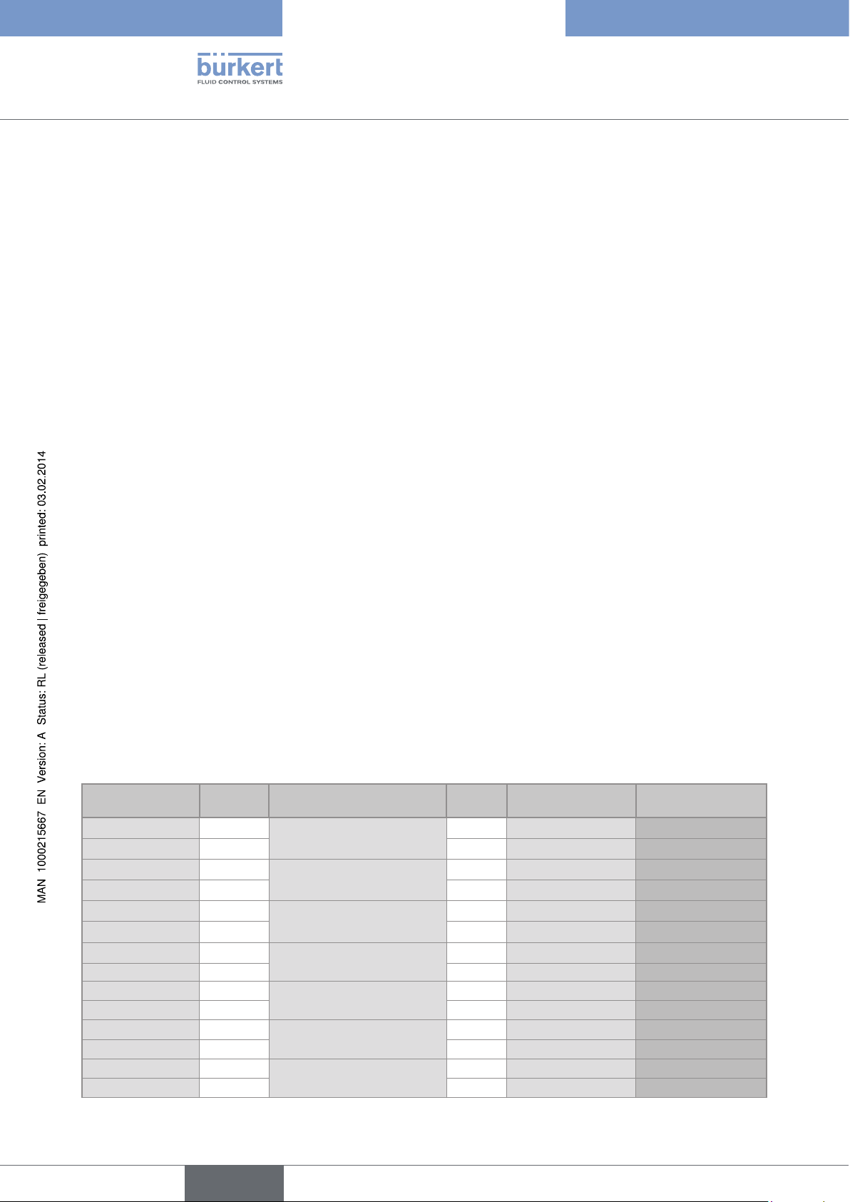
5.4. Available versions of the 8025 compact flowmeter
All the compact versions of the flowmeter 8025 have:
- a 4-20 mA current output;
- a pulse output ;
- two totalizers.
Supply voltage Seals Electrical connection Relays Sensor Order code
12-36 V DC FKM
12-36 V DC FKM
12-36 V DC FKM
12-36 V DC FKM
12-36 V DC FKM
12-36 V DC FKM
12-36 V DC FKM
12-36 V DC FKM
12-36 V DC FKM
12-36 V DC FKM
12-36 V DC FKM
12-36 V DC FKM
115/230 V AC FKM
115/230 V AC FKM
1)
1)
1)
1)
1)
1)
1)
1)
1)
1)
1)
1)
1)
1)
Male fixed connector - Hall, short
- Hall, long
Male fixed connector - Coil, short
- Coil, long
Terminal strips via 2 cable
glands
Terminal strips via 2 cable
glands
Terminal strips via 2 cable
glands
Terminal strips via 2 cable
glands
Terminal strips via 2 cable
glands
- Hall, short
- Hall, long
- Coil, short
- Coil, long
2 Hall, short
2 Hall, long
2 Coil, short
2 Coil, long
- Hall, short
- Hall, long
418762
418763
418764
418765
418802
418803
418804
418805
418778
418779
418780
418781
418423
418424
English
Page 11
Type 8025 / 8035
Description
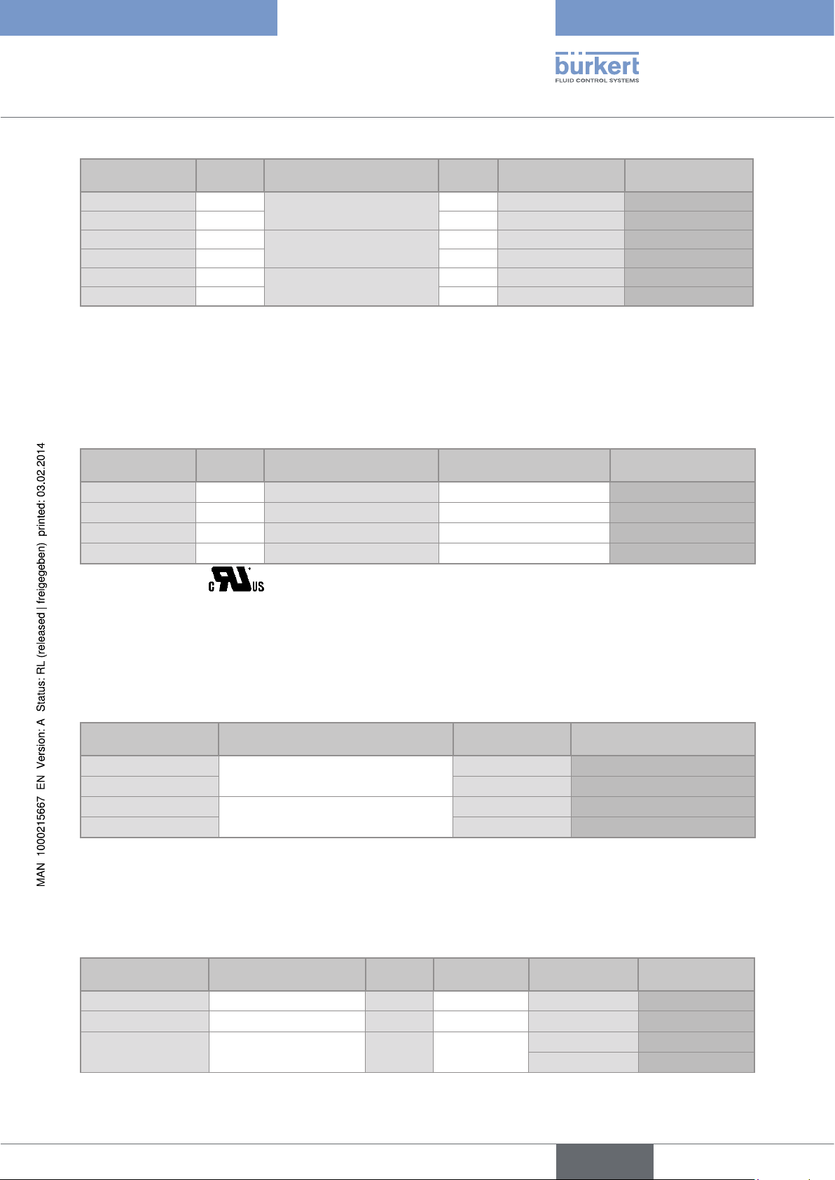
Supply voltage Seals Electrical connection Relays Sensor Order code
115/230 V AC FKM
115/230 V AC FKM
115/230 V AC FKM
115/230 V AC FKM
115/230 V AC FKM
115/230 V AC FKM
1)
Delivered with the device.
1)
1)
1)
1)
1)
1)
Terminal strips via 2 cable
glands
Terminal strips via 2 cable
glands
Terminal strips via 2 cable
glands
- Coil, short
- Coil, long
2 Hall, short
2 Hall, long
2 Coil, short
2 Coil, long
418425
418426
418431
418432
418433
418434
5.5. Available versions of the 8025 panel-mounted transmitter
All the panel versions of the 8025 have:
- a 4-20 mA current output;
- a pulse output;
- two totalizers.
Supply voltage Relays Electrical connection UR and CSA recognized Order code
12-36 V DC - Terminal strips no
12-36 V DC - Terminal strips yes
12-36 V DC 2 Terminal strips no
12-36 V DC 2 Terminal strips yes
2)
identified by the logo located on the name plate of the device.
2)
2)
418992
552725
418994
552726
5.6. Available versions of the 8025 wall-mounted transmitter
All the wall-mounted versions of the 8025 have:
- a 4-20 mA current output;
- a pulse output;
- two totalizers.
Supply voltage Electrical connection Relays Order code
12-36 V DC Terminal strips via 3 cable glands -
12-36 V DC 2
115/230 V AC Terminal strips via 3 cable glands -
115/230 V AC 2
418397
418396
418400
418399
5.7. Available versions of the SE35 electronic module
All the versions of the SE35 electronic module have:
- a 4-20 mA current output;
- a pulse output;
- two totalizers.
Supply voltage Electrical connection Relays Sensor
UR and CSA
recognized
12-36 V DC Male fixed connector - Hall no
12-36 V DC Male fixed connector - Coil no
12-36 V DC Terminal strips via 2 cable
glands
- Hall no
yes
2)
English
Order code
444005
423915
444006
553432
11
Page 12

Type 8025 / 8035
12
4
3
Description
Supply voltage Electrical connection Relays Sensor
12-36 V DC Terminal strips via 2 cable
- Coil no
glands
12-36 V DC Terminal strips via 2 cable
2 Hall no
glands
12-36 V DC Terminal strips via 2 cable
2 Coil no
glands
115/230 V AC Terminal strips via 2 cable
- Hall no
glands
115/230 V AC Terminal strips via 2 cable
2 Hall no
glands
2)
identified by the logo located on the name plate of the device.
UR and CSA
recognized
2)
yes
Order code
423916
444007
553433
423918
423922
423924
The ordering codes of the S030 sensor-fitting are listed in the related data sheet: consult the data sheet at: www.burkert.com.
5.8. Description of the name plate
FLOW SE35/8035 HALL SUPPLY: 12-36V ... 70 mA
Output: 1x4-20mA IP65
2xRel: 30V and 42V peak or 60V ... max.
S/N 11 026
Made in France
00552726 W44MG
8
67910
1. Measured quantity and type of the device
2. Type of sensor
3. Characteristics of the current output
4. Power supply and max. of current consumption
5
5. Protection class of the device
6. Manufacturing code
7. Conformity logo
8. Specification of the relay outputs
9. Serial number
10. Order code
Fig. 1: Name plate of the device
12
English
Page 13
Type 8025 / 8035
Technical data
6. TECHNICAL DATA
The following technical data are relevant for an 8025 compact or an 8035 flowmeter and for the remote 8025 flowmeter connected to a Bürkert flow sensor 8020 / 8030 in a "Low Power" version only.
6.1. Conditions of use
Ambient temperature
• 8025 compact, 115/230 V AC, not UR or CSA recognized
• 8035 compact, 115/230 V AC, not UR or CSA recognized
• Other versions, not UR or CSA recognized
• UR and CSA recognized versions
Air humidity < 80%, non condensated
Protection rating
• 8025 compact, and 8035
• 8025 compact and wall-mounted, 8035
• Housing, panel version
• non front parts, panel-mounted version
Degree of pollution (UR and CSA recognized versions) Degree 2 according to EN 61010 -1
Installation category (UR and CSA recognized versions) Category I according to UL61010-1
Max. height above sea level 2000 m
• -10 to 50 °C
• -10 to 50 °C
• -10 to 60 °C
• -10 to 40 °C
According to EN 60529
• IP65, device wired and cable glands tightened and cover
lid screwed tight.
• IP65, device wired, cable glands tightened, cover lid
screwed tight and entry item nuts of the cable glands
tightened at a screwing torque of 1.5 Nm.
• IP65, installation completed and closed cabinet
• IP20
6.2. Conformity to standards and directives
The device conforms to the EC directives through the following standards:
• EMC: EN 61000-6-2, EN 61000-6-3, EN 550022
• LVD: EN 61010-1
• Environnemental testing: Vibration: EN 60068-2-6, Shock: EN 60068-2-27.
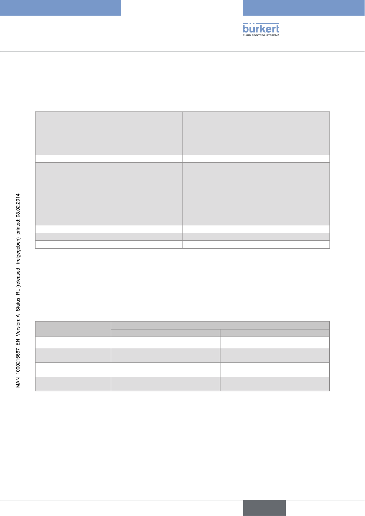
Pressure: article 3 paragraph 3 of the Pressure Directive 97/23/CE. Acc. to the Pressure Directive 97/23/CE: the device can
only be used in the following cases (depending on the max. pressure, the DN of the pipe and the fluid):
Type of fluid Conditions
8025 8035
Fluid group 1, paragraph 1.3.a DN25 only DN ≤ 25 only
Fluid group 2 paragraph 1.3.a
Fluid group 1 paragraph 1.3.b
Fluid group 2 paragraph 1.3.b DN ≤ 400 DN ≤ 200
1)
For the type 8035: S030 sensor-fitting, DN6 to DN65, in PP, PVC, PVDF, brass or stainless steel.
The UL recognized devices with variable key PU01 comply with the following standards:
• UL 61010-1
• CAN/CSA-C22.2 n° 61010-1
DN ≤ 32
or DN > 32 and PNxDN ≤ 1000
DN ≤ 25
or DN > 25 and PNxDN ≤ 2000
1)
DN ≤ 32
or DN > 32 and PNxDN ≤ 1000
PNxDN ≤ 2000
English
13
Page 14
6.3. General data
Pipe diameter
• 8025 flowmeter
• 8025 transmitter (remote versions)
• 8035 flowmeter
Type of fitting • S020, for a compact 8025
Type of fluid • liquid
Fluid temperature (compact versions)
• with fitting in PVC
• with fitting in PP
• with fitting in PVDF, stainless steel or brass
Fluid pressure (compact versions)
• DN20 (except for the DN specified p.22) to DN400
• DN06 to DN400
• DN06 to DN65
• S030, for a 8035
• viscosity: max. 300 cSt
• rate of solid particles: max. 1%
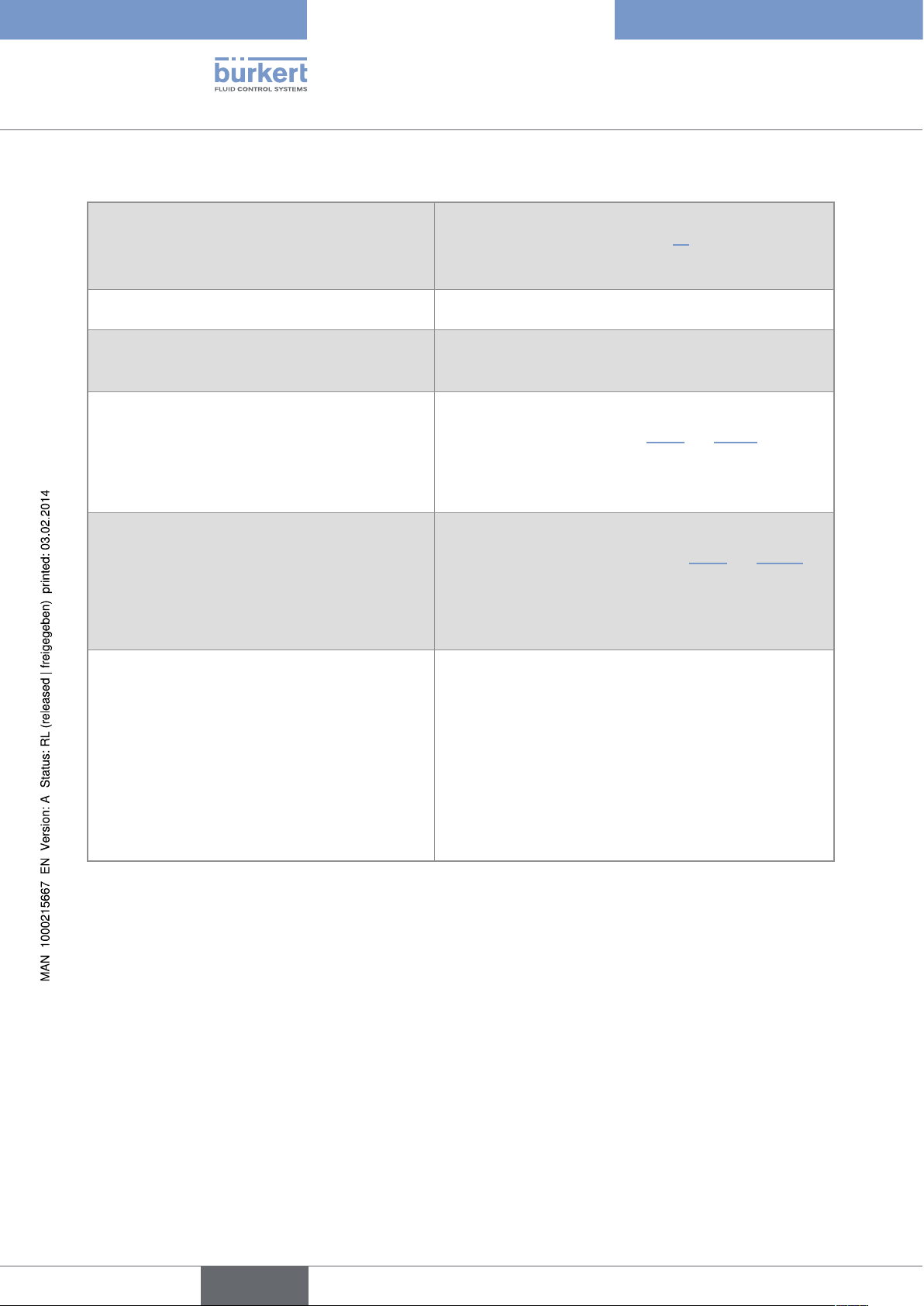
The fluid temperature may be restricted by the fluid pressure, the
material the flow sensor is made of and the material the S020 or
S030 fitting used is made of. See "Fig. 2" and "Fig. 3".
• 0 to +50 °C
• 0 to +80 °C
• -15 to +80 °C
The fluid pressure may be restricted by the fluid temperature, the
material the flow sensor is made of (only for the compact 8025) and
the material the fitting used is made of. See "Fig. 2" and "Fig. 3".
Type 8025 / 8035
Technical data
• 8025 compact
• 8035 with S030 fitting in plastic
• 8035 with S030 fitting in metal
• PN10
• PN10
• PN16 (PN40 on request)
Flow rate measurement
• Measurement range
- Sensor with pulse output (Hall)
- Sensor with sinus output (coil)
- 0.3 m/s to 10 m/s
- 0.5 m/s to 10 m/s
• Accuracy
- with a teach-in procedure
- 1 % of the measured value (at the value of the teach-in flow
rate)
- with the K factor of the fitting used
• Linearity
• Repeatability
1)
Determined in the following reference conditions: medium = water, water and ambient temperatures 20 °C, min. upstream and downstream
distances respected, appropriate pipe dimensions
1)
1)
- 2,5 % of the measured value
• ±0.5 % of the full scale
• ±0,4 % of the measured value
14
English
Page 15
Type 8025 / 8035
P (bar)
Technical data
P (bar)
11
10
9
PVDF
8
7
6
5
4
3
2
1
0
PVC + PP
PVC (PN10)
-15 0 +20 +40 +60
A
PP (PN10)
PVDF (PN10)
+80
Metal
T (°C)
A: range of use
Fig. 2: Fluid temperature /pressure dependency curves for the 8025 compact version, depending on the material the S020
fitting is made of
A
16
15
14
13
12
11
10
9
8
7
6
5
4
3
2
1
0
PVDF
PVC + PP
PVC (PN10)
-10 +10 +30 +50 +70 +90 +110
-30
A
Metal
PVDF (PN10)
PP (PN10)
T °C
A: range of use
Fig. 3: Fluid temperature /pressure dependency curves for the 8035 compact version, depending on the material the S030
sensor-fitting is made of
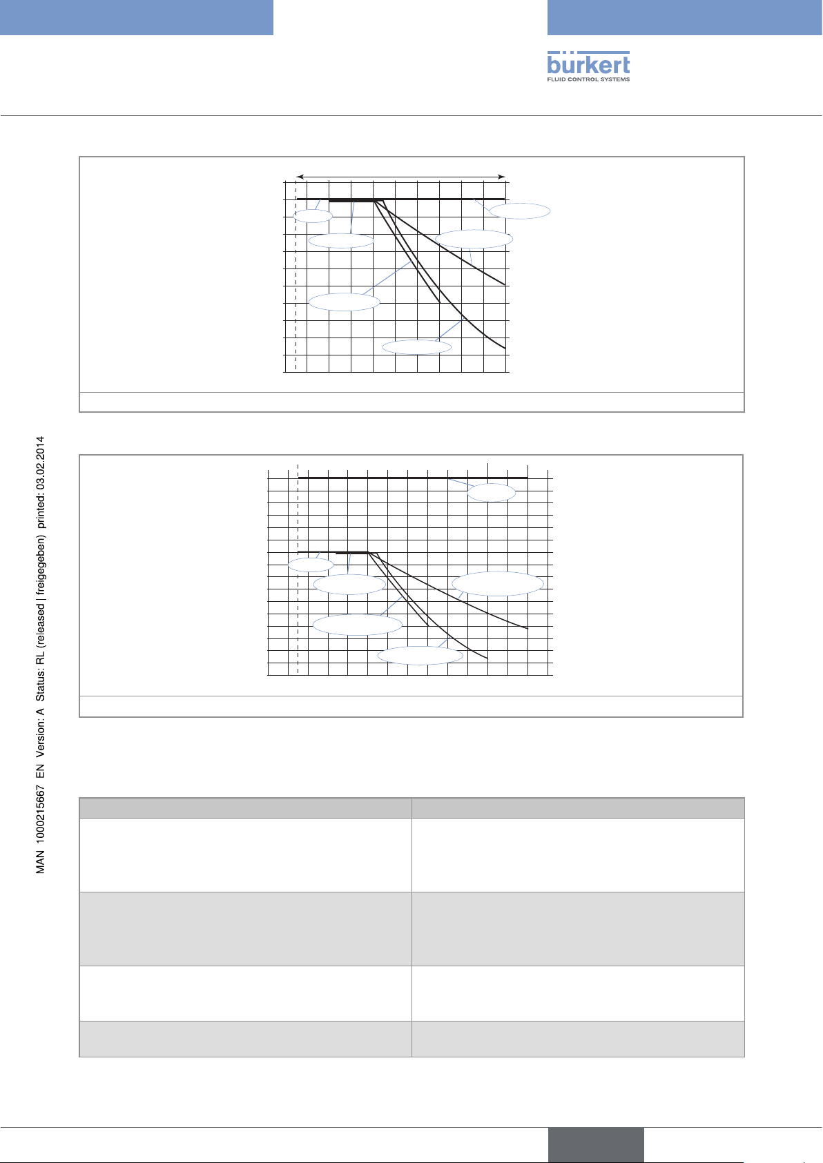
6.4. Mechanical data
Part Material
Sensor holder - Paddle-wheel
• 8025, compact versions
• 8025, remote versions
• 8035
Axis and bearings of the paddle-wheel
• 8025, compact versions
• 8025, remote versions
• 8035
Seals
• 8025, compact versions
• 8025, remote versions
Nut
• 8025, compact versions • PC
• PVDF
• Refer to the operating instructions of the remote sensor
• Refer to the operating instructions of the S030 sensor-fitting
• Ceramics
• Refer to the operating instructions of the remote sensor
• Refer to the operating instructions of the S030 sensor-fitting
• FKM (EPDM delivered with the device)
• Refer to the operating instructions of the remote sensor
15
English
Page 16

Part Material
88
88
R 90
91
164.50
203
136
(21)
82
85.5
(30)
70
Housing
• 8025, compact or panel versions
• 8025, wall-mounted versions
• 8035
• PC
• ABS
• PC
Cover
• 8025 compact versions or 8035
• 8025 panel versions
• 8025, wall-mounted versions
• PC (Cover with lid)
• PC
• ABS
Front foil Polyester
Screws (4) Stainless steel
Male fixed connector and female connector (type 2508) PA
Cable glands PA
Type 8025 / 8035
Technical data
16
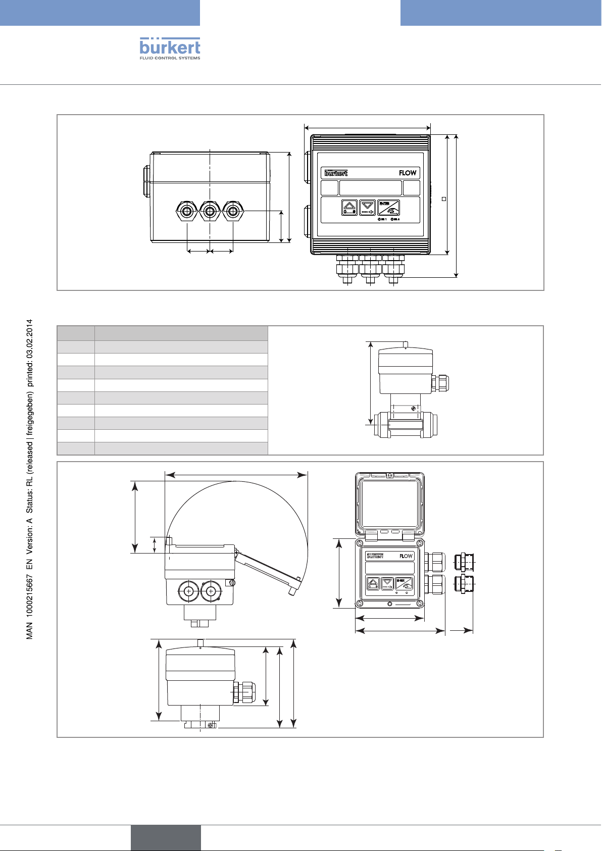
Fig. 4: Dimensions of 8025 compact flowmeter [mm]
English
Page 17
Type 8025 / 8035
88
88
76
25
38
REL1 REL2
Technical data
Tab. 1: Dimensions of 8025 compact flowmeter associated to an S020 fitting [height H in mm]
H
Tee fitting Saddle Spigot, in plastic
DN20 185
DN25 185
DN32 188
DN40 192 188
DN50 198 223 193
DN65 198 221 206 199
DN80 226 212 204
DN100 231 219 214
DN110 227
DN125 234 254 225
DN150 244 261 236
DN180 268
DN200 280 282 257
DN250 300 317
DN300 312 336
DN350 325 348
DN400 340
Welding tab with
radius, in stainless
steel
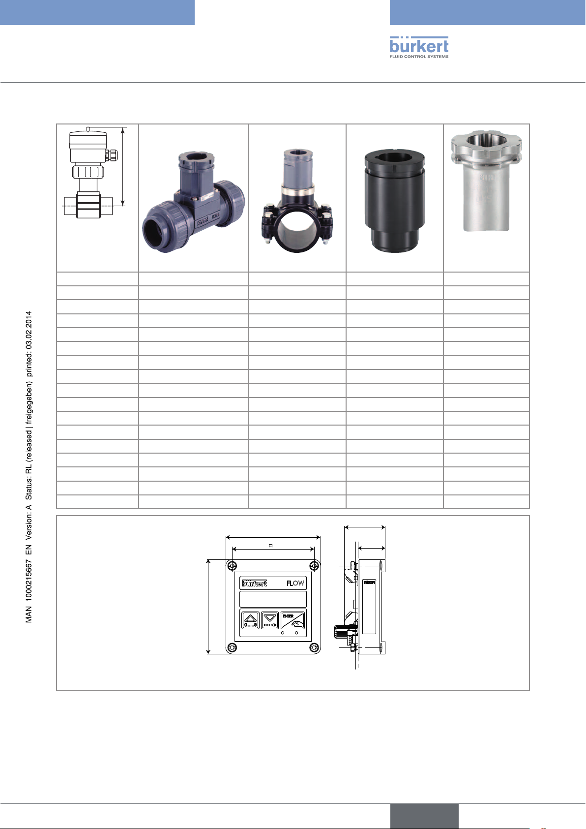
Fig. 5: Dimensions [mm] of the electronic module of the 8025 flowmeter a in panel version
17
English
Page 18
126
Type 8025 / 8035
Technical data
90
31.50
23
23
Fig. 6: Dimensions [mm] of the electronic module of the 8025 flowmeter in a wall-mounted version
Tab. 2: Dimension H [mm] of the 8035 depending on the DN of the S030 sensor-fitting
DN H with S030 sensor-fitting
06 134
08 134
15 139
20 137
H
25 137
32 140
40 144
50 151
65 151
180
120
143
18
91
21
88
105
75
104
114
Fig. 7: Dimensions [mm] of the SE35 electronic module of the 8035 flowmeter
88
116
103
English
Page 19

Type 8025 / 8035
Technical data
6.5. Electrical data
12-36 V DC power supply • filtered and regulated
• SELV circuit (safety extra low voltage), with a safe energy
level
• oscillation rate: ±10 %
Power source (not supplied) • limited power source according to paragraph 9.3 of
EN 61010-1 standard
• or class 2 source according to UL 1310/1585 and
EN 60950-1 standards
115/230 V AC power supply
• frequency
• supplied voltage
• current
• integrated protection
• power
Current consumption (without the consumption of the
4-20 mA output)
• 12-36 V DC version with relays
• 12-36 V DC version without relays
• 115/230 V AC compact version
• 115/230 V AC wall-mounted version
Pulse output
• type
• function
• frequency (f)
• electrical data
• duty cycle
• protection
Relay outputs
• operating
• electrical data of the load (non UL recognized devices)
• electrical data of the load (UL recognized devices)
Current output
• response time (10% to 90%)
• max. loop impedance, 12-36 V DC version
• max. loop impedance, 115/230 V AC version
• wiring, version without relays
• wiring, version with relays
Protection against polarity reversals yes
• 50/60 Hz
• 27 V DC, regulated
• max. 250 mA
• 250 mA time-delay fuse
• Compact version: 6 VA
• Wall-mounted version 3 VA
• 70 mA max. (at 12 V DC)
• 25 mA max. (at 12 V DC)
• 125 mA max. (at 27 V DC)
• 250 mA max. (at 27 V DC)
polarized, potential-free
• NPN/PNP (wiring dependant)
• pulse output, adjustable pulse value
• 2,5-400 Hz
• 5-36 V DC, 100 mA max., voltage drop 2,5 V DC at
100 mA
• 0,5
• galvanically insulated, and protected against overvoltages,
polarity reversals and short-circuits
• hysteresis, adjustable thresholds, normally open
• 230 V AC / 3 A
• 30 V AC max. and 42 V peak or 60 V DC max.
4-20 mA, sinking or sourcing mode (wiring dependant)
• 5,75 s (default)
• 900 W at 30 V DC, 600 W at 24 V DC, 50 W at 12 V DC
• 800 W
• 2-wire
• 3-wire
English
19
Page 20
Type 8025 / 8035
Technical data
6.6. Specifications of the connected flow sensor
Sensor input
• signal frequency
• pulse signal (Hall)
• sinus signal (coil)
• 2,5 to 400 Hz
• NPN, open collector
• typical sensitivity of 35 mV peak-peak, at 252 Hz
Sensor output
• power supply • 10-34 V DC (V+ minus 2 V DC), 1 mA max.
6.7. Electrical connection
Version Connection features
With male fixed
connector
Female connector (type 2508 supplied)
For the female connector type 2508 with order code 438811 and the female connector type 2509
(not supplied) with order code 162673, use a shielded cable.
• external diameter of the cable: 5 to 8 mm
• cross section of the wires: 0.2 to 1.5 mm
2
• max. length of the power supply, current output and pulse output connection cables: 50 m
With terminal strip,
with or without cable
glands
Shielded cable (not supplied):
• external diameter of the cable: 6 to 12 mm (4 to 6 mm when using a multiway seal)
• cross section of the wires: 0.2 to 1.5 mm
2
All Cross section of the local earthing wire: 0.75 mm
2
20
English
Page 21

Type 8025 / 8035
Installation
7. INSTALLATION
7.1. Safety instructions
DANGER
Risk of injury due to electrical voltage.
• Shut down the electrical power source of all the conductors and isolate it before carrying out work on the system.
• Observe all applicable accident protection and safety regulations for electrical equipment.
WARNING
Risk of injury due to nonconforming installation.
• The electrical and fluid installation can only be carried out by qualified and skilled staff with the appropriate tools.
• Install appropriate safety devices (correctly rated fuse and/or circuit-breaker); for the versions with 115/230 V AC power
supply, insert a protection device between phase and neutral.
• Respect standard NF C 15-100 / IEC 60364.
• Observe mounting instructions of the fitting.
Risk of injury due to unintentional switch on of power supply or uncontrolled restarting of the installation.
• Take appropriate measures to avoid unintentional activation of the installation.
• Guarantee a set or controlled restarting of the process subsequent to any intervention on the device.
WARNING
Risk of injury if the fluid pressure/temperature dependency is not respected.
• Take account of fluid temperature-pressure dependency according to the nature of the materials the fitting is made of
(see the technical data and the operating instructions of the fitting used).
• Comply with the Pressure Directive 97/23/CE.
Protect this device against electromagnetic interference, ultraviolet rays and, when installed outdoors, the
effects of the climatic conditions.
English
21
Page 22

Type 8025 / 8035
0.10.3 0.51 35 10
0.01
0.02
0.05
0.1
0.2
0.5
1
2
5
10
20
50
100
200
m
3
/h
0.2
0.5
1
2
5
10
20
50
100
200
500
1000
2000
3000
l/min
0.3
0.51 35 10
30
m/s
fps
US gpm
0.05
0.1
0.2
0.5
1
2
5
10
20
50
100
200
500
1000
DN 65
DN 50 (DN65)*
DN 40 (DN50)*
DN 32 (DN40)*
DN 25 (DN32)*
DN 20 (DN25)*
500
1000
2000
2000
5000
10000
5000
20000
5000
10000
20000
30000
50000
100000
DN 400
DN 350
DN 300
DN 250
DN 200
DN 150
DN 125
DN 100
DN 80
0.10.3 0.51 3
5
10
0.01
0.02
0.05
0.1
0.2
0.5
1
2
5
10
20
50
100
200
m
3
/h
l/min
0.30.5 13510
30
m/s
fps
gpm
0.05
0.1
0.2
0.5
1
2
5
10
20
50
100
200
500
1000
DN65
DN50 (DN65)*
DN40 (DN50)*
DN32 (DN40)*
DN25 (DN32)*
DN20 (DN25)*
DN15 (DN15 / DN20)*
DN08
DN06
0.2
0.5
1
2
5
10
20
50
100
200
500
1000
2000
3000
Installation
7.2. Installation of a compact version
7.2.1. Instructions for installing a compact version onto the pipe
The 8025 flowmeter has to be inserted into an S020 fitting mounted on a pipe.
The 8035 flowmeter has to be installed on the pipe using the S030 sensor-fitting.
→ Choose an S020 or S030 fitting appropriate to the velocity of the fluid inside the pipe: refer to the graphs below:
Tab. 3: Flow rate/ fluid velocity/ DN of S020 fitting and of S030 sensor-fitting diagram
Flow rate
22
1)
The device cannot be installed onto the following DN20 fittings:
* For the fittings:
• with external threads acc. to SMS 1145.
• with weld ends acc. to SMS 3008, BS 4825 / ASME BPE or DIN 11850 Rg2.
• Clamp acc. to SMS 3017 / ISO 2852, BS 4825 / ASME BPE or DIN 32676.
S020 fitting
English
Flow velocity
Example
S030 sensor-fitting
Flow rate
1)
Flow velocity
Example:
• Specification: if the nominal flow rate is 10 m
ideal flow velocity is between 2 and 3 m/s.
• Solution: intersection between flow rate and flow
velocity in the graph gives the appropriate pipe
diameter, DN40 (or DN50 for the asterisked fittings).
Example
3
/h, the
Page 23

Type 8025 / 8035
Installation
→ Install the device on the pipe in such a way that the upstream and downstream distances are respected according to the
design of the pipes, refer to standard EN ISO 5167-1 and "Fig. 8".
flow direction
50 x DN 5 x DN
With control valve Pipe with 2 elbows at 90° in 3
40 x DN 5 x DN
dimensions
25 x DN 5 x DN 20 x DN 5 x DN
Pipe with 2 elbows at 90° Pipe with 1 elbow at 90° or 1
T-piece
18 x DN 5 x DN 15 x DN 5 x DN
With pipe expansion With pipe reduction
Fig. 8: Upstream and downstream distances depending on the design of the pipes
→ Ensure that the pipe is always filled in the section around the device (see "Fig. 9").
→ When mounting vertically ensure that the flow direction is in an upward direction (see "Fig. 9").
Horizontal mounting
Correct Incorrect
Vertical mounting
flow direction
Correct Incorrect
Fig. 9: Filling of the pipe
→ Prevent the formation of air bubbles in the pipe in the section around the device (see "Fig. 10").
Correct
Correct Incorrect
Fig. 10: Air bubbles within the pipe
Incorrect
flow direction
→ If necessary, use a flow conditioner to improve measurement accuracy.
23
English
Page 24

7.2.2. Installation of the 8025 on the S020 fitting
→ Install the S020 fitting onto the pipe obeying the instructions in chap. “7.2.1”.
→ Check that there is a seal on the fitting and that it is not damaged. Replace the seal if
necessary.
6
1
→ Insert the nut 3 on the fitting 5.
→ Insert the snap ring 2 into the groove 4.
→ Check that the seal 6 is correctly inserted on the flow sensor.
2
3
4
5
Fig. 11: Installation of the 8025 on the S020 fitting
→ Insert the device 1 into the fitting.
If the mounting is correctly done the device cannot be turned around anymore.
→ Hand lock the assembly with nut 3.
Type 8025 / 8035
Installation
7.2.3. Installation of the SE35 electronic module onto the S030 sensor-fitting
→ Respect the installation instructions contained in the operating instructions of
the fitting used.
→ Insert the electronic module 2 into the S030 sensor-fitting.
→ Fix with a 30° rotation.
2
→ Tighten the side screw 3 to lock the electronic module to the sensor-fitting.
3
1
Fig. 12: Installation of the SE35 onto the S030 sensor-fitting
24
English
Page 25

Type 8025 / 8035
95
Installation
7.3. Installation of a panel version of the 8025 flowmeter
Install the panel version of the device in a cabinet with a protection class at least IP54 to ensure a degree of
pollution 2 inside the cabinet.
→ To cut the opening in the cabinet door, use the supplied cutting plan of the frontage of the electrical cabinet, respecting
the dimensions indicated in "Fig. 13".
80
76
50
95
80
76
50
Fig. 13: Dimensions [mm] of the electrical cabinet frontage cutting plan
Washer
Nut
Seal
Fig. 14: Installation of a 8025, panel version
Screw
Cable clip
→ Insert the 4 screws in the housing (from the front). If the cabinet door is too thick use the 4 supplied M4*25 screws.
→ Insert the seal on the external threads of the 4 screws (rear of the housing).
→ Put the assembly on the cutout, electronics turned to the inside of the cabinet.
→ Put the 4 washers on the 4 screws.
→ Put a nut on each of the 4 screws and tighten the nuts to secure the device to the cabinet.
→ Wire according to the instructions in chapter "8".
25
English
Page 26

Type 8025 / 8035
106 mm
Installation
7.4. Installation of a wall-mounted version of the 8025 transmitter
NOTE
Risk of material damage if the cable glands are not tightly screwed on the housing
• Before installing the wall-mounted housing on its support, tighten the nuts of the entry item of the cables glands at a
torque of 1.5 Nm.
The flow transmitter in a wall-mounted version has 4 holes in the bottom of the housing.
→ Remove the blanking strips covering the screws.
FLOW
Blanking strips
ENTER
0....9
Nut of the entry item
→ Loosen the 4 screws and open the cover to get access to the holes [1].
1
CURRENT
SOURCE SINK
1234PE
FLOW SENSOR
Without
Relays
COIL SENSOR
1
2
3 NC
4 NC
With
L+
NC
L+
Iout
Supply
12..36Vdc
NPN SENSOR
1 PULSE INPUT
2 -
SUPPLY
3 +
4 NC
REL2
LL-
3A/230VAC
P-
P+
PE
P-
P+
PE
PULSE
OUTPUT
FLOW SENSOR
COILNPN
REL1
T 250 mA
56789 10
1
Fig. 15: Installation of a wall-mounted version
→ Secure the housing to the support respecting the dimensions indicated in "Fig. 15".
→ Wire acc. to the instructions in chap. "8".
→ Close the housing and tighten the 4 screws of the cover.
LN
LN
230V
230V
1
106 mm
1
26
English
Page 27

Type 8025 / 8035
Wiring
8. WIRING
DANGER
Risk of injury due to electrical voltage.
• Shut down the electrical power source of all the conductors and isolate it before carrying out work on the system.
• Observe all applicable accident protection and safety regulations for electrical equipment.
Insert the supplied stopper gaskets into the unused cable glands of a wall-mounted or a compact version to ensure
the tightness of the device.
Only move the selectors when the power supply is off.
• Use a filtered and regulated 12-36 V DC power supply. The circuit has to be safety extra low voltage (SELV), with a
safe energy level.
• Make sure the installation is equipotential. See chap. "8.1".
• Use shielded cables with an operating temperature limit of 80 °C minimum.
• Do not install the cables near high voltage or high frequency cables; if a combined installation cannot be avoided, a
minimum space of 30 cm should be respected.
• Protect the power supply by means of a 300 mA fuse and a switch.
• Protect the relays by means of a max. 3 A fuse and a circuit breaker (depending on the process).
• Do not apply both a dangerous voltage and a safety extra-low voltage to the relays.
8.1. Making the installation equipotential
To ensure the equipotentiality of the installation (power supply - device - fluid):
→ Connect together the various earth spots in the installation to eliminate the potential differences that may occur between
different earthes.
→ Observe faultless earthing of the shield of the power supply cable, at both ends.
→ Connect the negative power supply terminal to the earth to suppress the effects of common mode currents. If this con-
nection cannot be made directly, a 100 nF/50 V capacitor can be fitted between the negative power supply terminal and
the earth.
→ Special attention has to be paid if the device is installed on plastic pipes because there is no direct earthing possible.
Proper earthing is performed by earthing together the metallic instruments such as pumps or valves, that are as close as
possible to the device. If no such instrument is near the device, insert metallic earth rings inside the plastic pipes upstream
and downstream the device and connect these parts to the same earth. The earth rings must be in contact with the fluid.
English
27
Page 28

+
-
(*)
12-36 V DC
Metal pipes
+
-
(*)
12-36 V DC
+
-
8025
(*)
8020
Valve, pump,... (or earth
rings, not provided,
inserted into the pipe)
Plastic pipes
Type 8025 / 8035
Wiring
Power supply
Power supply
*) If a direct earth connection is not possible, fit a 100 nF / 50 V capacitor between the negative power supply terminal and the earth.
Fig. 16: 8025 in a compact version and 8035, equipotentiality skeleton diagram with metal or plastic pipes
Power supply
+
-
(*)
Power supply
8025
Panel or wall-
mounted version
8030
Metal pipes
Panel or wall-
mounted version
28
Valve, pump,... (or earth
rings, not provided,
Plastic pipes
inserted into the pipe)
*) If a direct earth connection is not possible, fit a 100 nF / 50 V capacitor between the negative power supply terminal and the earth.
Fig. 17: 8025 in a remote version and equipotentiality skeleton diagram with metal or plastic pipes
English
Page 29

Type 8025 / 8035
300 mA
+
-
12-36 V DC
+
-
(*)
1
3
2
L+
L-
Wiring
8.2. Wiring the 8025 compact version and the 8035 with a 4 pin male fixed connector
3
1
2
Fig. 18: Pin assignment of the 4 pin male fixed connector
2
3
4
1
1: V+ (12-36 V DC)
2: Positive pulse output
3: L- ( 0 V DC)
: Negative pulse output
→ Unscrew the nut 1 of the cable gland.
→ Remove the terminal block 3 from the housing 2.
→ Insert the cable through the nut 1 then through the gasket
4, through the cable gland and finally through the housing
2.
→ Connect the wires on terminal block 3. See "Fig. 18", "Fig.
20" and "Fig. 21".
→ Position the terminal block 3 in steps of 90° then put it back
into the housing 2, pulling gently on the cable so that the
wires do not clutter the housing.
→ Tighten the nut 1 on the cable gland.
→ Place the seal 5 between the connector and the fixed con-
5
nector on the device and then plug the 2508 connector into
the fixed connector.
→ Insert and then tighten the screw 6 to ensure tightness and
6
Fig. 19: Assembling the female connector type 2508 (supplied)
correct electrical contact.
→ Wire the electrical supply and the current output using one of the wiring plans of "Fig. 20".
4-20mA input at external
(*) If direct earthing is not possible, insert a 100 nF / 50 V condensator between the negative terminal of the voltage supply and the earth.
instrument
L+
Power supply
300 mA
+
-
1
3
2
L-
+
-
12-36 V DC
(*)
4-20mA input at external
instrument
Power supply
Fig. 20: Possible wiring of the current output of a compact version with male fixed connector
29
English
Page 30

→ Wire the transistor output using one of the wiring plans of "Fig. 21".
300 mA
+
-
12-36 V DC
(*)
+
-
1
3
2
L+
L-
P+
P-
8025:
NPN
P+
P-
+
-
5-36 V DC
+
-
300 mA
+
-
12-36 V DC
(*)
1
3
2
L+
L-
P+
P-
8025:
PNP
P+
P-
+
-
5-36 V DC
Wiring of the pulse output in NPN mode
Power supply
Type 8025 / 8035
Wiring
Wiring of the pulse output in PNP mode
Power supply
PLC
(*) If direct earthing is not possible, insert a 100 nF / 50 V condensator between the negative terminal of the voltage supply and the earth.
Fig. 21: Wiring of the pulse output in NPN or PNP mode, of a compact version with male fixed connector
8.3. Configuring the selectors
Only move the selectors when the power supply is off.
→ Before wiring the device, configure the selectors on the electronic board: see chap. "8.3.1" to "8.3.3".
8.3.1. FLOW SENSOR selector
The FLOW SENSOR selector makes it possible to configure the type of flow sensor: coil or Hall.
For the version with male fixed connector, the selector is factory-set depending on the output signal of the flow
sensor mounted on the device.
PLC
30
L-
P-
L+
PE
Without
With
Relays
P+
PE
NC
L-
P-
L+
P+
PE
Iout
Supply
PULSE
12..36Vdc
OUTPUT
FLOW SENSOR
COIL NPN
FLOW SENSOR
COIL NPN
Fig. 22: Position of the FLOW SENSOR connector on the electronic board
Tab. 4: Positioning of the FLOW SENSOR selector depending on the output signal of the flow sensor
Version of the flowmeter Output signal of the remote sensor Position of the FLOW SENSOR selector
All Pulse, NPN (hall) NPN
All Sinus (coil) COIL
8.3.2. SOURCE/SINK selector
The Source/Sink selector makes it possible to set the 4-20 mA current output of the versions with relays, in sourcing or in
sinking mode. Set the selector depending on the type of wiring.
L-
P-
PE
L+
P+
PE
NC
L-
P-
L+
P+
PE
Iout
Supply
PULSE
12..36Vdc
OUTPUT
FLOW SENSOR
COIL NPN
Fig. 23: Position of the Source / Sink selector
SOURCE SINK
Without
Relays
SOURCE SINK
Without
With
Relays
English
Page 31

Type 8025 / 8035
Wiring
Tab. 5: Positioning of the Source / Sink selector depending on the wiring of the current output of a version with relays
Wiring the 4-20 mA output Position of the Source/Sink selector on a version with relays
Not wired (jumper wire in place) SOURCE
Sourcing mode SOURCE
Sinking mode SINK
8.3.3. 115/230 V AC selector
The 115/230 V AC selector makes it possible to configure the supply voltage of the device in a 115/230 V AC version.
→ Energize the device with a
230 V AC voltage.
230V
115V
→ Energize the device with a
115 V AC voltage.
Fig. 24: Supply voltage selector on a 115/230 V AC version
8.4. Wiring the 8025 in a compact version and the 8035, with or without relays, with cable glands
8.4.1. Wiring instructions
Seal the unused cable gland using the stopper gasket supplied to make sure the device is tight.
→ Unscrew the nut of the cable gland.
→ Remove the transparent disc inside the cable gland.
→ Insert the stopper gasket.
→ Screw the nut back.
→ Lift the transparent lid after having unfastened the screw.
→ Untighten the 4 screws then remove the cover from the device.
→ For the versions with relays, insert the cable clip.
→ Before wiring the device insert the supplied cable
SOURCE SINK
Relays
Without
With
P-
L+
P+
PE
Iout
Supply
PULSE
12..36Vdc
OUTPUT
FLOW SENSOR
COIL NPN
PE
L-
P-
L+
P+
PE
NC
L-
clips into the slots of the electronic board and of the
115/230 V AC power supply board if the device has
such a board.
Fig. 25: Inserting the cable clips
→ Pass the cables through the cable glands.
→ Set the selectors according to chap. "8.3".
→ Connect the terminal block according to the indications of chap. "8.4.2" to "8.4.6".
31
English
Page 32

8.4.2. Wiring of the relays (versions with relay output)
• 1: relay 1 connection
SOURCE SINK
Relays
Without
With
P-
L+
P+
PE
Iout
Supply
PULSE
12..36Vdc
OUTPUT
FLOW SENSOR
COIL NPN
PE
L-
P-
L+
P+
PE
NC
L-
• 2: relay 2 connection
• 3: fixation slots
→ Always secure the relays connection cables in the slots
marked 3 (see "Fig. 25").
Type 8025 / 8035
Wiring
+
2
-
+
1
-
Load 1 Load 2
3
Fig. 26: Wiring of the relays
8.4.3. Wiring the 8025 compact version and the 8035, 12-36 V DC, without relays, with cable glands
→ Before wiring the device, configure the selectors on the electronic board (see chap. "8.3").
Terminal block 1
NC: not connected
L+: positive power supply
L-: negative power supply
PE: wiring of the PE between the main board and the protection
board
P-: negative pulse output
P+: positive pulse output
A
Terminal block 2 PE
Wiring of the cable shields
Connector 3: connection of the flow sensor
Without
Relays
With
NC
Iout
L+
L+
Supply
12..36Vdc
1
LL-
2
PE
P-
P+
PE
P-
P+
PE
PULSE
OUTPUT
FLOW SENSOR
COILNPN
3
32
Switch A: see chap. "8.3.1"
Fig. 27: Terminal assignment of a 12-36 V DC compact version without relays, with cable glands
4-20mA input at
external instrument
+
-
Without
NC
SOURCESINK
With
Relays
Iout
(*) If direct earthing is not possible, insert a 100 nF / 50 V condensator between the negative terminal of the voltage supply and the earth.
300 mA
L+
L+
Supply
12..36Vdc
LL-
Power supply
+
-
12-36 V DC
P-
P+
PE
PE
P-
P+
PE
PULSE
OUTPUT
(*)
FLOW SENSOR
COIL NPN
4-20mA input at
external instrument
SOURCESINK
Power supply
300 mA
+
-
Without
NC
With
Relays
Iout
12..36Vdc
+
-
12-36 V DC
(*)
L-
P-
L+
P+
PE
PE
L-
P-
L+
P+
PE
Supply
PULSE
OUTPUT
FLOW SENSOR
COIL NPN
Fig. 28: Possible wiring of the current output of a compact version, 12-36 V DC, without relays, with cable glands
English
Page 33

Type 8025 / 8035
Supply
12..36Vdc
FLOW SENSOR
COIL NPN
L+
L-
PE
P-
P+
NC
L+
L-
PE
P-
P+
Iout
PULSE
OUTPUT
Without
With
Relays
300 mA
+
-
12-36 V DC
(*)
+
-
8025:
NPN
P+
P-
+
-
5-36 V DC
PE
Supply
12..36Vdc
FLOW SENSOR
COIL NPN
L+
L-
PE
P-
P+
NC
L+
L-
PE
P-
P+
Iout
PULSE
OUTPUT
Without
With
Relays
+
-
300 mA
+
-
12-36 V DC
(*)
P+
P-
8025:
PNP
+
-
5-36 V DC
PE
Wiring
Wiring of the pulse output in NPN mode
Power supply
PLC
Wiring of the pulse output in PNP mode
Power supply
PLC
(*) If direct earthing is not possible, insert a 100 nF / 50 V condensator between the negative terminal of the voltage supply and the earth.
Fig. 29: Wiring, in NPN or PNP mode, of the pulse output of a compact version, 12-36 V DC, without relays, with cable
glands
8.4.4. Wiring the 8025 compact version and the 8035, 12-36 V DC, with relays, with cable glands
→ Before wiring the device, configure the selectors on the electronic board (see chap. "8.3").
Terminal block 1
1
B
SOURCESINK
Without
Relays
With
NC
Iout
L+
L+
Supply
12..36Vdc
PE
L-
PE
L-
6
PP-
PULSE
OUTPUT
PE
P+
P+
2
FLOW SENSOR
COIL NPN
Iout: 4-20 mA output
L+: positive power supply
L-: negative power supply
PE: wiring of the PE between the main board and the
protection board
P-: negative pulse output
P+: positive pulse output
A
Terminal block 2 PE
Wiring of the cable shields
Connector 3: connection of the flow sensor
Terminal block 4: wiring of relay 1, see chap. "8.4.2"
Terminal block 5: wiring of relay 2:, see chap. "8.4.2"
Jumper wire 6: jumper wire to be removed if the 4-20 mA
3
output is connected
5
4
Switch A: see chap. "8.3.1"
B
Switch
Fig. 30: Terminal assignment of a 12-36 V DC compact version with relays, with cable glands
: see chap. "8.3.2"
33
English
Page 34

Type 8025 / 8035
Supply
12..36Vdc
FLOW SENSOR
COIL NPN
SOURCE SINK
L+
L-
PE
P-
P+
NC
L+
L-
PE
P-
P+
Iout
PULSE
OUTPUT
Without
With
Relays
300 mA
+
-
12-36 V DC
(*)
+
-
8025:
NPN
P+
P-
+
-
5-30 V DC
PE
Supply
12..36Vdc
FLOW SENSOR
COIL NPN
SOURCE SINK
L+
L-
PE
P-
P+
NC
L+
L-
PE
P-
P+
Iout
PULSE
OUTPUT
Without
With
Relays
+
-
300 mA
+
-
12-36 V DC
(*)
P+
P-
8025:
PNP
+
-
5-30 V DC
PE
Wiring
Wiring of the current output in sourcing mode
4-20mA input at exter-
nal instrument
Source/Sink selector
(see chap. "8.3.2")
SOURCE SINK
300 mA
+
-
Iout
L-
L+
Without
PE
NC
L-
With
L+
Relays
PE
Iout
Supply
12..36Vdc
Power supply
+
-
12-36 V DC
P-
P+
PE
P-
P+
PULSE
OUTPUT
COIL NPN
(*)
FLOW SENSOR
Wiring of the current output in sinking mode
4-20mA input at exter-
nal instrument
Source/Sink selector
(see chap. "8.3.2")
SOURCE SINK
300 mA
+
-
Iout
L-
L+
Relays
Without
PE
NC
L-
With
L+
PE
Iout
Supply
12..36Vdc
Power supply
+
-
12-36 V DC
P-
P+
PE
P-
P+
PULSE
OUTPUT
(*)
FLOW SENSOR
COIL NPN
(*) If direct earthing is not possible, insert a 100 nF / 50 V condensator between the negative terminal of the voltage supply and the earth.
If the current output is wired, remove the jumper wire between the terminals Iout and L-.
Fig. 31: Wiring, in sourcing or sinking mode, of the current output of a compact version, 12-36 V DC, with relays, with cable
glands
Wiring of the pulse output in NPN mode
Power supply
Wiring of the pulse output in PNP mode
Power supply
PLC
PLC
(*) If direct earthing is not possible, insert a 100 nF / 50 V condensator between the negative terminal of the voltage supply and the earth.
Fig. 32: Wiring in NPN or PNP mode, of the pulse output of a compact version, 12-36 V DC, with relays, with cable glands,
34
English
Page 35

Type 8025 / 8035
Wiring
8.4.5. Wiring the 8025 compact version and the 8035, 115/230 V AC, without relays, with cable glands
→ Before wiring the device, configure the selector on the electronic board (see chap. "8.3").
Terminal block 1
The red wire is wired on the NC terminal to make the wiring of the
4-20 mA output easier (see "Fig. 34"). The jumper wire 4 between L+ and
NC energizes the NC terminal.
1
2
B
A
L-
L+
Without
NC
Iout
L+
Supply
12..36Vdc
L-
With
Relays
4
PE
P-
P+
PE
P-
P+
PE
PULSE
OUTPUT
FLOW SENSOR
COIL NPN
230V
T 125 mA
NPEL
{
3
7
Switch A: see chap. "8.3.1"
Switch
B
: see chap. "8.3.3"
Fig. 33: Terminal assignment of a 115/230V AC compact version without relays, with cable glands
4-20mA input at
external instrument
6
NC: not connected (terminal for the
wiring of the 4-20 mA output)
L+ (red wire, factory wired)
PE: wiring of the PE between the main
board and the protection board
L- (black wire, factory wired)
P-: negative pulse output
P+: positive pulse output
Terminal block 2 PE
Shield wiring (green/yellow wire,
factory wired)
5
Connector 3: connection of the flow
sensor
Jumper wire 4: jumper wire to be
removed if the 4-20 mA output is
connected
Time-delay fuse 5: fuse to protect the
115 V AC or 230 V AC power supply
Earth terminal 6 of the housing:
internally connected to the earth plug
Terminal block 7: wiring of the
115/230 V AC power supply
+
-
PE
L-
P-
L+
Without
With
Relays
P+
PE
NC
L-
P-
L+
P+
PE
Iout
Supply
PULSE
12..36Vdc
OUTPUT
FLOW SENSOR
COIL NPN
230V
T 125 mA
NPEL
{
115/230 V AC power supply
If the current output is wired, remove the jumper wire between the terminals Iout and L+.
Fig. 34: Wiring of the current output of a compact version, 115/230 V AC, without relays, with cable glands
English
35
Page 36

Type 8025 / 8035
Supply
12..36Vdc
FLOW SENSOR
COIL NPN
L+
L-
PE
P-
P+
NC
L+
L-
PE
P-
P+
Iout
PULSE
OUTPUT
Without
With
Relays
230V
T 125 mA
N PEL
{
5-36 V DC
+
-
8025:
NPN
P+
P-
+
-
PE
Supply
12..36Vdc
FLOW SENSOR
COIL NPN
L+
L-
PE
P-
P+
NC
L+
L-
PE
P-
P+
Iout
PULSE
OUTPUT
Without
With
Relays
230V
T 125 mA
N PEL
{
5-36 V DC
8025:
PNP
P+
P-
+
-
+
-
PE
Wiring
Wiring of the pulse output in NPN mode
PLC
115/230 V AC power supply
Wiring of the pulse output in PNP mode
PLC
115/230 V AC power supply
(*) If direct earthing is not possible, insert a 100 nF / 50 V condensator between the negative terminal of the voltage supply and the earth.
Fig. 35: Wiring, in NPN or PNP mode, of the pulse output of a 115/230 V AC compact version, without relays, with cable
glands
8.4.6. Wiring the 8025 compact version and the 8035, 115/230 V AC, with relays, with cable glands
→ Before wiring the device, configure the selectors on the electronic board (see chap. "8.3").
Terminal block 1
21
A
B
C
SOURCE SINK
6
Without
Relays
L+
NC
With
L+
Iout
Supply
12..36Vdc
PE
L-
P-
P+
PE
L-
P-
P+
PE
PULSE
OUTPUT
FLOW SENSOR
COILNPN
230V
T 125 mA
NPEL
{
8
lout: 4-20 mA output
L+ (red wire, factory wired)
L- (black wire, factory wired)
PE: wiring of the PE between the main board and the
protection board
P-: negative pulse output
P+: positive pulse output
7
Terminal block 2 PE
Shield wiring (green/yellow wire, factory wired)
36
3
5
4
9
Connector 3: connection of the flow sensor
Terminal block 4: wiring of relay 1: see chap. "8.4.2"
Terminal block 5: wiring of relay 2: see chap.
Switch A: see chap. "8.3.1"
"8.4.2".
Jumper wire 6: jumper wire to be removed if the
Switch
Switch
B
: see chap. "8.3.3"
: see chap. "8.3.2"
C
4-20 mA output is connected
Time-delay fuse 7: fuse to protect the 115 V AC or
230 V AC power supply
Terminal 8: earth terminal, internally connected to
the earth plug
Terminal block 9: wiring of the 115/230 V AC
power supply
Fig. 36: Terminal assignment of a 115/230 V AC compact version with relays, with cable glands
English
Page 37

Type 8025 / 8035
Wiring
4-20mA input at
external instrument
+
-
PE
L-
P-
L+
SOURCE SINK
Without
Relays
NC
With
Iout
12..36Vdc
P+
PE
L-
P-
L+
P+
PE
Supply
PULSE
OUTPUT
FLOW SENSOR
COIL NPN
230V
T 125 mA
NPEL
{
115/230 V AC power supply
If the current output is wired, remove the jumper wire between the terminals Iout and L+.
Fig. 37: Wiring in sourcing mode of the current output of a compact version, 115/230 V AC, with relays, with cable glands
4-20mA input at
external instrument
+
-
SOURCESINK
Without
Relays
NC
With
Iout
L+
Supply
12..36Vdc
P+
PE
L-
P-
P+
PE
PULSE
OUTPUT
FLOW SENSOR
COIL NPN
230V
PE
L-
P-
L+
T 125 mA
NPEL
{
115/230 V AC power supply
If the current output is wired, remove the jumper wire between the terminals Iout and L+.
Fig. 38: Wiring in sourcing mode of the current output of a compact version, 115/230 V AC, with relays, with cable glands
English
37
Page 38

Type 8025 / 8035
Supply
12..36Vdc
FLOW SENSOR
COIL NPN
SOURCE SINK
L+
L-
PE
P-
P+
NC
L+
L-
PE
P-
P+
Iout
PULSE
OUTPUT
Without
With
Relays
NPEL
230V
T 125 mA
{
5-36 V DC
+
-
8025:
NPN
P+
P-
+
-
PE
Wiring
Wiring of the pulse output in NPN mode
PLC
Wiring of the pulse output in PNP mode
+
5-36 V DC
-
PLC
+
-
PE
L-
P-
L+
SOURCE SINK
Without
Relays
With
P+
PE
NC
L-
P-
L+
P+
PE
Iout
Supply
PULSE
12..36Vdc
OUTPUT
8025:
P+
P-
PNP
FLOW SENSOR
COIL NPN
230V
T 125 mA
NPEL
{
115/230 V AC
power supply
115/230 V AC
power supply
(*) If direct earthing is not possible, insert a 100 nF / 50 V condensator between the negative terminal of the voltage supply and the earth.
Fig. 39: Wiring, in NPN or PNP mode, of the pulse output of a 115/230 V AC compact version, with relays, with cable
glands
→ Connect the relays according to chap. "8.4.2".
8.5. Connecting the flow sensor to the 8025 transmitter, panelmounted version or wall-mounted version
→ Configure the FLOW SENSOR selector on the electronic board (see chap. "8.3").
→ Connect the remote flow sensor to the FLOW SENSOR terminal block of the electronic board by respecting the pin
assignment depending on the output type of the remote sensor, either sinus (COIL) or pulse output (NPN).
Pulse, NPN
1
234PE
Shielding of the sensor
cable
NC
{
1
234PE
NC
VV+
Shielding of the sensor
cable
38
Flow sensor with a sinus output
Flow sensor with a pulse output (NPN)
NC = Not connected
Fig. 40: Wiring of the remote flow sensor to the 8025 transmitter
8.6. Wiring the 8025 remote (wall-mounted or panel), 12-36 V DC, with or without relays
8.6.1. Wiring the 8025, remote version, 12-36 V DC, without relays
→ For a wall-mounted version, obey the wiring instructions of chap. "8.7.1".
→ Configure the FLOW SENSOR selector on the electronic board (see chap. "8.3").
→ Connect the flow sensor to the transmitter according to chap. "8.5".
English
Page 39

Type 8025 / 8035
Supply
12..36Vdc
FLOW SENSOR
COILNPN
L+
L-
PE
P-
P+
NC
L+
L-
PE
P-
P+
Iout
PULSE
OUTPUT
Without
With
Relays
NPN SENSOR
1 PULSE INPUT
2 3 +
4 NC
SUPPLY
1234PE
REL1
REL2
COIL SENSOR
1
2
3 NC
4 NC
4
6
3
5
A
21
B
PE
Wiring
1
2
NC: not connected
L+: positive power supply
L-: negative power supply
PE: wiring of the PE between the main board and the
Terminal block 1
Relays
COIL SENSOR
1
2
3 NC
4 NC
1234PE
Without
With
L+
NC
L+
Iout
Supply
12..36Vdc
NPN SENSOR
1 PULSE INPUT
2 -
SUPPLY
3 +
4 NC
REL2
L-
PE
L-
PE
PP-
PULSE
OUTPUT
P+
P+
PE
FLOW SENSOR
COIL NPN
REL1
3
protection board
P-: negative pulse output
A
P+: positive pulse output
Terminal block 2 PE
Wiring of the cable shields
Connector 3: connection of the flow sensor see chap.
"8.5"
Switch A: see chap. "8.3.1"
Fig. 41: Terminal assignment of a panel-mounted or wall-mounted version, 12-36 V DC, without relays
The wiring of the current output and the wiring of the pulse output of the panel or wall-mounted transmitter, 12-36 V DC,
without relays, are the same as for a compact flowmeter, 12-36 V DC, without relays, with cable glands.
→ Wire the current output according to "Fig. 28" of chap. "8.4.3".
→ Wire the pulse output according to "Fig. 29" of chap. "8.4.3".
8.6.2. Wiring the 8025, remote version, 12-36 V DC, with relays
→ For a wall-mounted version, obey the wiring instructions of chap. "8.7.1".
→ Before wiring the device, configure the selectors on the electronic board (see chap. "8.3").
→ Connect the flow sensor to the transmitter according to chap. "8.5".
Terminal block 1
Iout: 4-20 mA output
L+: positive power supply
L-: negative power supply
PE: wiring of the PE between the main board and the protection
board
P-: negative pulse output
P+: positive pulse output
Terminal block 2 PE
Wiring of the cable shields
Switch A: see chap. "8.3.1"
Switch
Fig. 42: Terminal assignment of a panel-mounted or wall-mounted version, 12-36 V DC, with relays
: see chap. "8.3.2"
B
Terminal block 3: wiring of relay 1, see chap. "8.4.2"
Terminal block 4: wiring of relay 2, see chap. "8.4.2"
Connector 5: connection of the flow sensor: see chap. "8.5"
Jumper wire 6: jumper wire to be removed if the 4-20 mA
output is connected
39
English
Page 40

Type 8025 / 8035
Wiring
→ Insert the cable clips: see "Fig. 25".
The wiring of the current output and the pulse output of the panel or wall-mounted transmitter, 12-36 V DC, without relays, are
the same as for a compact flowmeter, 12-36 V DC, with relays, with cable glands.
→ Wire the current output according to "Fig. 31" of chap. "8.4.4".
→ Wire the pulse output according to "Fig. 32" of chap. "8.4.4".
8.7. Wiring the 8025, wall-mounted version, 115/230 V AC, with or without relays
8.7.1. Wiring instructions for a wall-mounted version
Seal the unused cable gland using the supplied stopper gasket to make sure the device is tight.
→ Unscrew the nut of the cable gland.
→ Remove the transparent disc inside the cable gland.
→ Insert the stopper gasket
→ Screw the nut back.
→ Connect the flow sensor to the remote transmitter according to chap. "8.5".
→ Configure the selectors on the electronic board: see chap. "8.3".
→ Loosen the nuts of the cable glands.
→ Insert each cable through a nut then through the cable gland, using the cable glands as shown in "Fig. 43".
Cables of the outputs
Flow sensor cable
Fig. 43: Using the cable glands
Power supply cable,
12-36 V DC or
115/230 V AC
→ Remove the two terminal blocks (marked 4 and 6 in "Fig. 44" chap. "8.7.2" and "Fig. 48" chap. "8.7.3") from the housing.
→ For the versions with relays, insert the cable clips: see "Fig. 25".
→ Depending on the version (with or without relays), wire the device according to chap. "8.7.2" or "8.7.3".
→ Insert the two terminal blocks (marked 4 and 6 in "Fig. 44" chap. "8.7.2" and "Fig. 48" chap. "8.7.3") into their original
position.
→ Letting the housing stay completely open, secure the power supply cable, the flow sensor connection cable and,
depending on the version, the relay connection cables, with the cable clips.
→ Tighten the cable glands making sure the cable in the housing is long enough to allow complete opening of the housing.
→ Close the cover.
→ Tighten the 4 screws.
→ Put the blanking strips on the housing.
40
English
Page 41

Type 8025 / 8035
Wiring
8.7.2. Wiring the 8025, wall-mounted version, 115/230 V AC, without relays
→ Before wiring the device, obey the instructions of chap. "8.7.1".
Terminal block 1
NC: not connected
L+ (red wire, factory wired)
L- (green wire, factory wired)
PE: wiring of the PE between the main board
and the protection board
P- (brown wire, factory wired)
3
B
P+ (white wire, factory wired)
21 A
L-
PE
P-
L+
NC
Iout
12..36Vdc
NPN SENSOR
P+
PE
L-
P-
L+
P+
PE
Supply
PULSE
OUTPUT
FLOW SENSOR
SUPPLY
REL2
COILNPN
REL1
1234PE
FLOW SENSOR
Without
Relays
COIL SENSOR
1
2
3 NC
4 NC
With
1 PULSE INPUT
2 3 +
4 NC
8
7
Switch A: see chap. "8.3.1"
Switch
: see chap. "8.3.3"
B
Terminal block 2 PE
Shield wiring (green/yellow wire, factory wired)
Time-delay fuse 3: fuse to protect the
230V
230V
230V
115 V AC or 230 V AC power supply
T 250 mA
Terminal block 4
LN
LN
{
56789 10
Wiring of the 115/230 V AC power supply
Jumper wire 5: jumper wire to be removed if
the 4-20 mA output is connected
6
5
4
Terminal block 6
Terminal 5: 4-20 mA output
Terminal 6: positive 27 V DC power supply,
available to energize an external instrument
Terminal 7: 0V (earth of the power supply
available to energize an external instrument)
Terminal 8: cable shields
Terminal 9: negative pulse output
Terminal 10: positive pulse output
Marker 7: all the cables must be fitted here
Connector 8: connection of the flow sensor
Fig. 44: Terminal assignment of a wall-mounted version, 115/230 V AC, without relays
41
English
Page 42

L-
L+
Without
NC
L-
With
L+
Relays
Iout
Supply
12..36Vdc
NPN SENSOR
COIL SENSOR
1 PULSE INPUT
1
2 -
2
SUPPLY
3 +
3 NC
4 NC
4 NC
1234PE
FLOW SENSOR
REL2
4-20mA input at
external instrument
Type 8025 / 8035
Wiring
PE
P-
P+
PE
P-
P+
PE
PULSE
OUTPUT
FLOW SENSOR
COILNPN
REL1
T 250 mA
56789 10
+
-
LN
LN
230V
230V
230V
{
Fig. 45: Wiring of the current output of a wall-mounted version without relays
L-
PE
P-
L+
NC
L+
Iout
Supply
12..36Vdc
NPN SENSOR
1 PULSE INPUT
2 -
SUPPLY
3 +
4 NC
P+
PE
L-
P-
P+
PE
PULSE
OUTPUT
FLOW SENSOR
COILNPN
REL2
REL1
T 250 mA
1234PE
FLOW SENSOR
Without
Relays
COIL SENSOR
1
2
3 NC
4 NC
With
56789 10
+
5-36 VDC
-
+
-
Fig. 46: Wiring in NPN mode of the pulse output of a wall-mounted version without relays
LN
LN
{
230V
230V
230V
42
English
Page 43

Type 8025 / 8035
Wiring
Without
With
Relays
COIL SENSOR
1
2
3 NC
4 NC
1234PE
FLOW SENSOR
L+
NC
L+
Iout
Supply
12..36Vdc
NPN SENSOR
1 PULSE INPUT
2 -
SUPPLY
3 +
4 NC
PE
L-
P-
P+
PE
L-
P-
P+
PE
PULSE
OUTPUT
FLOW SENSOR
COILNPN
REL2
REL1
T 250 mA
LN
LN
{
230V
230V
230V
56789 10
+
5-36 V DC
-
+
-
Fig. 47: Wiring in PNP mode of the pulse output of a wall-mounted version without relays
English
43
Page 44

Type 8025 / 8035
Wiring
8.7.3. Wiring the 8025, wall-mounted version, 115/230 V AC, with relays
→ Before wiring the device, obey the instructions of chap. "8.7.1".
Terminal block 1
Iout: 4-20 mA output (green wire, factory wired)
L+ (red wire, factory wired)
L- (black wire, factory wired)
PE: wiring of the PE between the main board
and the protection board
P- (brown wire, factory wired)
P+ (white wire, factory wired)
21 A
C
CURRENT
SOURCE SINK
1234PE
FLOW SENSOR
Without
Relays
COIL SENSOR
1
2
3 NC
4 NC
With
NC
Iout
NPN SENSOR
1 PULSE INPUT
2 3 +
4 NC
12..36Vdc
PE
L-
P-
L+
P+
PE
L-
P-
L+
P+
PE
Supply
PULSE
OUTPUT
FLOW SENSOR
3A/230VAC
COILNPN
REL1
SUPPLY
REL2
10
9
8
7
Switch A: see chap. "8.3.1"
Switch
Switch
: see chap. "8.3.3"
B
: see chap. "8.3.2"
C
3
B
Terminal block 2 PE
Shield connection (green/yellow wire, factory
wired)
Time-delay fuse 3: fuse to protect the
230V
230V
230V
115 V AC or 230 V AC power supply
T 250 mA
Terminal block 4
LN
LN
{
56789 10
Wiring of the 115/230 V AC power supply
Jumper wire 5: jumper wire to be removed if the
4-20 mA output is connected
6
5
4
Terminal block 6
Terminal 5: 4-20 mA output
Terminal 6: positive 27 V DC power supply,
available to energize an external instrument
Terminal 7: 0V (earth of the power supply
available to energize an external instrument)
Terminal 8: cable shields
Terminal 9: negative pulse output
Terminal 10: positive pulse output
44
Marker 7: all the cables must be fitted here
Terminal block 8: wiring of relay 1, see chap.
"8.4.2"
Terminal block 9: wiring of relay 2, see chap.
"8.4.2"
Connector 10: connection of the flow sensor
Fig. 48: Terminal assignment of a wall-mounted version, 115/230 V AC, with relays
The wiring of the pulse output of a wall-mounted version with relays is the same as the wiring of a version without relays.
→ Refer to "Fig. 46" and "Fig. 47".
English
Page 45

Type 8025 / 8035
Wiring
CURRENT
SOURCE SINK
1234PE
FLOW SENSOR
Without
Relays
COIL SENSOR
1
2
3 NC
4 NC
With
NC
Iout
12..36Vdc
NPN SENSOR
1 PULSE INPUT
2 3 +
4 NC
PE
L-
P-
L+
P+
PE
L-
P-
L+
P+
PE
Supply
PULSE
OUTPUT
FLOW SENSOR
3A/230VAC
REL1
COILNPN
T 250 mA
SUPPLY
REL2
LN
LN
230V
230V
230V
{
56789 10
-
4-20mA input at
+
external instrument
Fig. 49: Wiring in sinking mode of the current output of a wall-mounted version, 115/230 V AC, with relays
CURRENT
SOURCE SINK
1234PE
FLOW SENSOR
Relays
COIL SENSOR
1
2
3 NC
4 NC
Without
With
L+
NC
L+
Iout
Supply
12..36Vdc
NPN SENSOR
1 PULSE INPUT
2 -
SUPPLY
3 +
4 NC
REL2
LL-
3A/230VAC
PE
P-
P+
PE
P-
P+
PE
PULSE
OUTPUT
FLOW SENSOR
COILNPN
REL1
T 250 mA
LN
LN
230V
230V
230V
{
56789 10
-
4-20mA input at
+
external instrument
Fig. 50: Wiring in sourcing mode of the current output of a wall-mounted version, 115/230 V AC, with relays
English
45
Page 46

Type 8025 / 8035
operating and commissioning
9. OPERATING AND COMMISSIONING
9.1. Safety instructions
WARNING
Risk of injury due to nonconforming operating.
Non-conforming operating could lead to injuries and damage the device and its surroundings.
• The operators in charge of operating must have read and understood the contents of this manual.
• In particular, observe the safety recommendations and intended use.
• The device/installation must only be operated by suitably trained staff.
WARNING
Danger due to non-conforming commissioning.
Non-conforming commissioning could lead to injuries and damage the device and its surroundings.
• Before commissioning, make sure that the staff in charge have read and fully understood the contents of the manual.
• In particular, observe the safety recommendations and intended use.
• The device / the installation must only be commissioned by suitably trained staff.
• Before commissioning, set the K Factor of the fitting used. See chap. "9.6.3".
9.2. Operating levels of the device
The device has two operating levels: the Process level and the Configuration level.
The Process level makes it possible:
• to read the flow rate measured by the device, the value of the current transmitted on the 4-20 mA analogue output, the
values of both the daily and main totalizers;
• to reset the daily totalizer;
• to access the Configuration level.
The Configuration level has two menus (Parameters, Test) and makes it possible:
• to set the device parameters;
• to test some device settings.
Tab. 6: Default settings of the device
Function Default value
LANGUAGE English
UNIT of the flow rate L/min, 1 decimal
UNIT of the totalizers L
Number of decimal positions 1
4 mA current output 0.000
20 mA current output 100.0
K FACTOR
FILTER
Value of a pulse (PU)
Unit of the pulse output
Relay 1- 40.0
Relay 1+ 50.0
Relay 1 inverted no
Relay 2- 80.0
Relay 2+ 90.0
Relay 2 inverted no
51.20
5
00.05
L
46
English
Page 47

Type 8025 / 8035
operating and commissioning
Process level
12.6 L/MiN.
16.45 MA
0......9
87654 L
231 L.
+
0......9
> 2 s
To reset the daily totalizer (identified by a dot after the volume
units).
> 5 s
ENTER
Configuration level
0......9
Parameters Menu
LANGUAGE
UNit
K-FACtOR
CURRENt
0......9
PULSE
RELAy
FiLtER
> 5 s
ENTER
0......9
Test Menu
OFFSEt
SPAN
FREqUENC
FLOw
END
Fig. 51: Diagram of the levels of the device
tOtAL
END
Process level
English
47
Page 48

Type 8025 / 8035
operating and commissioning
9.3. Description of the navigation keys and the status LEDs
• Selecting the displayed parameter
• Scrolling up the parameters
• Incrementing the figure selected
• Confirming the settings
LED indicating the status of the relay
2
(LED ON = contact closed)
• Scrolling through the parameters
• Selecting the figure on the left
Fig. 52: Description of the display
9.4. Using the navigation keys
You want to... Press...
move between parameters within a level or a menu.
access the Parameters menu.
access the Test menu.
reset the daily totalizer, from the Process level.
select the displayed parameter.
confirm the displayed value.
modify a numerical value.
•
0......9
•
ENTER
0......9
0......9
displayed in the Process level
ENTER
ENTER
0......9
•
LED indicating the status of the relay 1
(LED ON = contact closed)
to go the next parameter.
to go to the previous parameter.
+ simultaneously for 5 s, in the Process level
ENTER
+ +
simultaneously for 5 s, in the Process level
+ simultaneously for 2 s, when the daily totalizer is
to increase the blinking digit.
48
English
to select the digit at the left of the blinking digit.
•
0......9
+ to move the decimal point.
•
Page 49

Type 8025 / 8035
operating and commissioning
9.5. Details of the Process level
This level is active by default when the device is energized.
12.6 L/MiN.
16.45 MA
0......9
87654 L
231 L.
Value of the measured flow rate, displayed in the unit chosen in the "UNIT" parameter of the
Parameters menu.
Value of the current output, proportional to the measured flow rate.
Value of the main totalizer, volume of fluid counted by the device since the last reset.
Value of the daily totalizer (identified by a dot after the volume units), volume of fluid counted by
the device since the last reset.
0......9
+
> 2 s
Resetting the daily totalizer.
Fig. 53: Diagram of the Process level
9.6. Details of the Parameters menu
To access the Parameters menu, simultaneously press keys
This menu comprises the following configurable parameters:
ENTER
for at least 5 s.
LANGUAGE
UNit
K-FACtOR
CURRENt
0......9
PULSE
RELAy
FiLtER
tOtAL
Choosing the display language
Choosing the flow rate unit, the number of decimals and the unit the totalizers are displayed in.
Entering the K factor of the fitting used or have it defined through a teach-in procedure.
Choose the flow rate range related to the 4-20 mA output current.
Parameterizing the pulse output.
Configuring the relays. This function only appears on devices with relays.
Choosing the filter level of the measured flow rate, on the displayed flow rate and the current
output. Ten dampening levels are available.
Resetting both totalizers.
Saving the changes made within the Parameters menu and returning
to the Process level.
END 12.6 L/MiN.
Fig. 54: Diagram of the Parameters menu
Process level
English
49
Page 50

9.6.1. Choosing the display language
When the device is energized for the first time, the display language is English.
LANGUAGE ENGLiSh
0......9
DEUtSCh
→ The chosen language is active as soon as the
pressed
FRANçAiS
itALiANO
UNit
Type 8025 / 8035
operating and commissioning
ENTER
key is
Fig. 55: Diagram of the "LANGUAGE" parameter of the Parameters menu
→ If you do not want to adjust another parameter, go to the "END" parameter of the Parametersmenu and press
ENTER
to
save the settings and go back to the Process level.
9.6.2. Choosing the flow rate units, the number of decimals and the units of the
totalizers
The max. flow rate that can be displayed depends on the number of decimals chosen:
• 9999 if the number of decimals = 0.
• 999,9 if the number of decimals = 1.
• 99,99 if the number of decimals = 2.
• 9,999 if the number of decimals = 3.
The max. flow rate that can be displayed by the totalizers depends on the volume unit chosen:
• 9 999 999 if the volume unit chosen is "litre";
3
• 999 999 if the volume unit chosen is "m
• When the flow rate unit is changed convert the flow rate values set within the "CURRENT", "PULSE" and "RELAYS"
parameters of the Parameters menu.
The "UNIT" parameter makes it possible to choose:
• the flow rate units;
• a fixed number of decimals (choice 0, 1, 2 or 3) to display the flow rate in the Process level;
• the volume units of the totalizers if the unit previously chosen is in litres, in m
" or "gallon".
3
or in gallons.
50
English
Page 51

Type 8025 / 8035
operating and commissioning
UNit
0......9
FLOw RAtE
0......9
Lit/SEC
→ Choose the flow rate unit.
→ Confirm.
Lit/MiN
Lit/h
M3/MiN
M3/h
US GAL/S
ENTER
DEC Pt 3
US GAL/M
DEC Pt 2
0......9
US GAL/h
DEC Pt 1
iMP GA/S
DEC Pt 0
iMP GA/M
GA/h
If the chosen unit is in litres, m3 or in gallons.
→ Choose the number
of decimal positions.
→ Confirm.
ENTER
tOtAL
0......9
LitRE
M3
US GAL
→ Choose the totalizer unit.
→ Confirm.
ENTER
iMP GAL
K-FACtOR
Fig. 56: Diagram of the "UNIT" parameter of the Parameters menu
→ If you do not want to adjust another parameter, go to the "END" parameter of the Parameters menu and press
save the settings and go back to the Process level.
ENTER
to
English
51
Page 52

Type 8025 / 8035
operating and commissioning
9.6.3. Entering the K factor of the fitting used
The device determines the flow rate in the pipe using the fitting K factor.
The K factor of the fitting used can be entered here. The device may also determine the K factor using a teach-in procedure:
see "Fig. 58".
The K factor of the fitting used is in the operating instructions of the fitting.
The operating instructions of the Bürkert fittings can be found on the CD delivered with the device or on the internet
at: www.burkert.com.
K-FACtOR
ENTER ENTER
tEACh NO
ENTER
Fig. 57: Entering the K factor of the fitting used
The teach-in is done depending on a known volume.
→ Prepare a tank with a known volume.
→ Stop the fluid circulation.
→ Confirm "TEACH Y.": "FILL END." is displayed.
K-FACtOR tEACh NO
ENTER
K=0000.00
0......9
K=0117.60CURRENt
The display shows the K factor of the fitting,
last entered or determined using a Teach-In
procedure.
→ Edit the parameter.
→ Enter the K factor (value between 0,0001
and 9999,9) of the fitting used.
→ Confirm the displayed value.
52
0......9
ENTER
tEACh y FiLL END
→ Charge the pipe to fill the tank.
→ When the tank is full, confirm "FILL
END"
Do not enter a volume value equal
to 0,0 because the K Factor calculated would be equal to 0,0 and
the device would not operate.
→ Enter the volume (value > 0,0 and
≤ 9999,9) of fluid that passed in the
circuit.
→ Confirm.
The device calculates the
K factor of the fitting and
displays it.
ENTER
K=0079.30CURRENt
Fig. 58: Teach-in procedure depending on a volume
ENTER
0000.0 L
0......9
ENTER
0100.00 L
→ If you do not want to adjust another parameter, go to the "END" parameter of the Parameters menu and press
save the settings and go back to the Process level.
ENTER
to
English
Page 53

Type 8025 / 8035
operating and commissioning
9.6.4. Configuring the current output
The 4-20 mA output provides an electrical current, the value of which reflects the flow rate measured by the device.
Example of relation between the measuring range and the current output:
mA
20
4
20 180
l/min
→ To invert the output signal, give a lower flow rate value to the 20 mA current value than to the 4 mA current value.
→ To disable the current output, set both range bounds, 4 and 20 mA, to zero. In this case the output delivers a constant current of 4 mA.
The units and number of decimal digits are those set within the "UNIT" parameter for the display of the current output
values.
CURRENt
ENTER
4=0000
→ Enter the flow rate value related to the a
0......9
4 = 28.00
4 mA current, in the unit chosen in the
"UNIT".parameter.
20=0000
→ Enter the flow rate value related
to the a 20 mA current, in the unit
chosen in the "UNIT" parameter.
PULSE
Fig. 59: Configuration of the current output
ENTER
0......9
20 = 6.000
→ If you do not want to adjust another parameter, go to the "END" parameter of the Parameters menu and press
save the settings and go back to the Process level.
9.6.5. Configuring the pulse output
This parameter makes it possible to enter the volume of liquid related to a pulse.
Example: a pulse is emitted every 5 m3 volume has passed through the device.
PULSE LitRE
RELAy
ENTER
0......9
M3
US GAL
iMP GAL
→ Choose the volume unit of
a pulse.
PU=000.00
0......9
ENTER
PU=005.00
→ Enter the volume of a liquid
related to a pulse.
ENTER
to
Fig. 60: Configuration of the pulse output
If the message "PU H LIM" or "PU L LIM" is displayed, see chap. "10.3".
→ If you do not want to adjust another parameter, go to the "END" parameter of the Parameters menu and press
save the settings and go back to the Process level.
English
ENTER
to
53
Page 54

Type 8025 / 8035
operating and commissioning
9.6.6. Configuring the relays
This parameter makes it possible to set the switching thresholds and the operating behaviour, inverted or not, of each relay.
Enter values such as 1- ≤ 1+ and/or 2- ≤ 2+.
Both relays work in an hysteresis operating.
RELAy
ENTER
1-= 0000
→ Enter a flow rate value, associated to the low threshold of
0......9
relays 1, in the unit chosen in the "UNIT" parameter.
→ Confirm.
1-= 0008
ENTER
1+ = 0000
0......9
→ Enter a flow rate value, associated to
the high threshold of relays 1, in the unit
chosen in the "UNIT" parameter.
ENTER
iNv NO
0......9
iNv yES
iNv NO
0......9
iNv yES
ENTER
1+ = 0010
→ Choose the sense of operating,
inverted or not inverted.
→ Confirm
ENTER
2-= 0000
2-= 0040
→ Enter a flow rate value, associated to
the high threshold of relays 2, in the unit
chosen in the "UNIT" parameter.
→ Confirm.
→ Choose the sense of operating,
inverted or not inverted.
→ Confirm.
→ Confirm.
→ Enter a flow rate value, associated to
the low threshold of relays 2, in the unit
chosen in the "UNIT" parameter.
0......9
→ Confirm.
ENTER
2+ = 0000
0......9
ENTER
2+ = 0044
54
FiLtER
Fig. 61: Configuration of the relays threshold in hysteresis operating
→ If you do not want to adjust another parameter, go to the "END" parameter of the Parameters menu and press
save the settings and go back to the Process level.
English
ENTER
to
Page 55

Type 8025 / 8035
operating and commissioning
Sense of operation not inverted Sense of operation inverted
Contact
OFF
Inverted NO
Contact
Inverted YES
OFF
ON
(2-) (2+)
1-
1+
Flow rate
ON
(2-) (2+)
1-
Fig. 62: Hysteresis operating
9.6.7. Configuring the filter of the measured flow rate
This parameter makes it possible to dampen the fluctuations:
• of the display;
• of the current output.
Ten filters are available.
The following table gives the response time for each filter (10% to 90%):
FILTER Response time FILTER Response time
0 0,15 s 5 6 s
1 0,7 s 6 10 s
2 1,4 s 7 19 s
3 2,5 s 8 33 s
4 3,5 s 9 50 s
ENTER
FiLtER FiLtER 0
0......9
FiLtER 9
→ Choose the filter.
→ Confirm.
1+
Flow rate
tOtAL
Fig. 63: Diagram of the "FILTER" parameter of the Parameters menu
→ If you do not want to adjust another parameter, go to the "END" parameter of the Parameters menu and press
save the settings and go back to the Process level.
9.6.8. Resetting both totalizers
This parameter makes it possible to reset both totalizers.
tOtAL RES NO
ENTER
0......9
RES yES
→ Choose to reset the two totalizers or not.
→ Confirm.
END
Fig. 64: Diagram of the "TOTAL" parameter of the Parameters menu
ENTER
to
55
English
Page 56

The daily totalizer can be reset from the Process level. See chap. "9.4".
Type 8025 / 8035
operating and commissioning
→ If you do not want to adjust another parameter, go to the "END" parameter of the Parameters menu and press
save the settings and go back to the Process level.
9.7. Details of the Test menu
To access the Test menu, simultaneously press keys
This menu comprises the following configurable parameters:
OFFSEt
SPAN
0......9
FREqUENC.
FLOw
Adjusting the OFFSET of the current output. See chap. "9.7.1".
Adjusting the SPAN of the current output. See chap. "9.7.2".
Reading the rotational frequency of the paddle wheel. See chap. "9.7.3".
Simulating a flow rate to check the correct operating of the outputs. See chap. "9.7.4".
0......9
END
Go back to the Process level by saving the new OFFSET and
SPAN adjustments.
ENTER
for at least 5 s.
12.6 L/MiN.
Process level
ENTER
to
56
When "END" is confirmed and the display indicates "OFFSET": enter new offser and/or span values.
Fig. 65: Diagram of the Test menu
9.7.1. Adjusting the OFFSET of the current output
This parameter makes it possible to adjust the 4 mA current value transmitted on the 4-20 mA output.
→ Connect a multimeter into the measurement loop.
OFFSEt
ENTER
OF= 4.00
→ The device generates a 4 mA current.
→ Measure the current given on the 4-20 mA output using a multimeter.
→ Enter the value displayed by the multimeter. The permitted offset
range is 3 to 5 mA.
→ Confirm.
SPAN
ENTER
Fig. 66: Adjustment of the OFFSET
0......9
OF= 4.02
→ Adjust the default 20 mA current value: see chap. "9.7.2".
The adjusted value of the default 4 mA value (parameter "OFFSET") is taken into account when leaving the parameter
"SPAN".
→ If you do not want to adjust another parameter, go to the "END" parameter of the Test menu and press
settings and go back to the Process level.
ENTER
to save the
English
Page 57

Type 8025 / 8035
operating and commissioning
9.7.2. Adjusting the SPAN of the current output
This parameter makes it possible to adjust the 20 mA current value transmitted on the 4-20 mA output.
→ Connect a multimeter into the measurement loop.
SPAN
ENTER
SP= 20.00
→ The device generates a 20 mA current.
→ Measure the current given on the 4-20 mA output using a
multimeter.
→ Enter the value displayed by the multimeter. The permitted span
range is 15 to 21,50 mA.
→ Confirm.
FREqUENC
ENTER
Fig. 67: Adjustment of the SPAN
0......9
SP= 19.90
→ If you do not want to adjust another parameter, go to the "END" parameter of the Test menu and press
settings and go back to the Process level.
9.7.3. Reading the rotational frequency of the paddle wheel
FREqUENC 195.3 hz
ENTER
ENTER
FLOw
Fig. 68: Diagram of the "FREQUENC." parameter of the Test menu
→ If you do not want to adjust another parameter, go to the "END" parameter of the Test menu and press
settings and go back to the Process level.
ENTER
ENTER
to save the
to save the
9.7.4. Checking the outputs behaviour
This parameter makes it possible to simulate a flow rate in order to check that the outputs are behaving as expected by the
configuration made.
FLOw
ENTER
00.00 L/S
0......9
→ Enter a flow rate value, in the unit chosen in the "UNIT" parameter.
46.25 L/S
→ Confirm by pressing the
"FLOW" parameter.
ENTER
key. the display returns on the
→ Check that the outputs are behaving as expected.
ENTER
→ To test another value, press
→ To exit the checking, press or
Fig. 69: Diagram of the "FLOW" parameter of the Test menu
→ If you do not want to adjust another parameter, go to the "END" parameter of the Test menu and press
settings and go back to the Process level.
.
0......9
.
ENTER
to save the
57
English
Page 58

Type 8025 / 8035
Maintenance and troubleshooting
10. MAINTENANCE AND TROUBLESHOOTING
10.1. Safety instructions
DANGER
Danger due to electrical voltage.
• Shut down the electrical power source of all the conductors and isolate it before carrying out work on the system.
• Observe all applicable accident protection and safety regulations for electrical equipment.
Risk of injury due to high pressure in the installation.
• Stop the circulation of fluid, cut off the pressure and drain the pipe before loosening the process connections.
Risk of injury due to high fluid temperatures.
• Use safety gloves to handle the device.
• Stop the circulation of fluid and drain the pipe before loosening the process connections.
Risk of injury due to the nature of the fluid.
• Respect the prevailing regulations on accident prevention and safety relating to the use of hazardous products.
WARNING
Risk of injury due to nonconforming maintenance.
• Maintenance must only be carried out by qualified and skilled staff with the appropriate tools.
• Guarantee a defined or controlled restarting of the process after a power supply interruption.
10.2. Cleaning the device
The device can be cleaned with a cloth dampened with water or a detergent compatible with the materials the device is made of.
Please feel free to contact your Bürkert supplier for any additional information.
10.3. If you encounter problems
Message
displayed
ERROR 3 Memory read error: the user settings
Possible cause Recommended action
→ Switch the device off.
are lost.
→ Switch the device on.
→ If the message is still displayed, press the ENTER key to
acknowledge the error: the device operates with the default
settings.
→ Adjust the device again.
→ If the message appears frequently, send the device back to your
supplier.
ERROR 4 Memory read error: the totalizer values
are lost.
→ Press the ENTER key to acknowledge the error: the values of the
totalizers are set to those of the last start of the device.
→ Check the values of the totalizers.
ERROR 5 Memory read error: the user settings
and the totalizer values are lost.
→ Press the ENTER key to acknowledge the error: the device
operates with the default settings and the values of the totalizers
are set to those of the last start of the device.
→ Adjust the device again.
→ Check the values of the totalizers.
→ If the message appears frequently, send the device back to your
supplier.
ERROR 6 Memory read error: the totalizer values
are lost.
→ Press the ENTER key to acknowledge the error: the totalizers are
reset.
58
English
Page 59

Type 8025 / 8035
Maintenance and troubleshooting
Message
displayed
ERROR 7 Memory read error: the user settings
PWR FAIL
PU H LIM The pulse value times the K factor of
PU L LIM The pulse value times the K factor of
Possible cause Recommended action
and the totalizer values are lost.
The supply voltage is too low.
• The voltage at the device terminals
is lower than 12 V.
• The impedance of the current
measurement loop is too high (see
chap. "6.5").
the device is > 1000000.
The entered volume for a pulse is too
high.
the device is < 1.
The entered volume for a pulse is too
low.
→ Press the ENTER key to acknowledge the error: the totalizers are
reset.
→ Send the device back to your supplier.
→ Adjust the supply voltage so that the voltage at the device ter-
minals is between 12 V and 36 V.
→ Enter a lower volume / pulse. See chap. "9.6.5".
→ Check the K factor value. See chap. "9.6.3".
→ Enter a higher volume / pulse. See chap. "9.6.5".
→ Check the K factor value. See chap "9.6.3".
English
59
Page 60

Type 8025 / 8035
Spare parts and accessories
11. SPARE PARTS AND ACCESSORIES
ATTENTION
Risk of injury and/or damage caused by the use of unsuitable parts.
Incorrect accessories and unsuitable replacement parts may cause injuries and damage the device and the surrounding
area.
• Use only original accessories and original replacement parts from Bürkert.
The defective electronic board or housing of your device can be replaced.
• Contact the local Bürkert office.
11.1. Spare parts 8025, compact version
3
2
1
4
5
14
15
12
87
13
16
9
1110
6
60
Fig. 70: Exploded view of the spare parts of a 8025, compact version
Position Fig. 70 Designation Order code
1 115/230 V AC supply voltage board + replacement instructions 553168
2 Female connector with cable gland (type 2508) 438811
3 Female connector type 2509 with NPT 1/2 '' reduction 162673
4+6+7+9 Set including:
• 2 M20*1.5 cable glands
• 2 neoprene flat seals for cable gland or plug
449755
• 2 M20*1.5 screw plugs
• 2 2*6 mm multi-way seals
English
Page 61

Type 8025 / 8035
Spare parts and accessories
Position Fig. 70 Designation Order code
5+6+7 Set including:
• 2 M20*1.5 / NPT1/2'' reductions (with mounted seals)
• 2 neopren flat seals for the screw plug
551782
• 2 M20*1.5 screw plugs
8+9+14 Set including:
• 1 M20*1.5 cable gland stopper gasket
• 1 2*6 mm multi-way seal for a cable gland
551775
• 1 black EPDM seal for the flow sensor
• 1 mounting instruction sheet
10 + 2 Housing with female connector type 2508, snap ring and nut 425524
11 Housing for 2 M20*1.5 cable glands, snap ring and nut 425526
12 Snap ring 619205
13 Nut 619204
14 Set including:
• 1 FKM green seal
552111
• 1 EPDM black seal
15 Flow sensor (coil) for DN15 to DN100 (1/4" - 4") pipes + replacement instructions 633366
Flow sensor (Hall) for DN15 to DN100 (1/4" - 4") pipes + replacement instructions 418316
16 Flow sensor (coil) for DN ≥ 100 (≥ 5") + replacement instructions 634757
Flow sensor (Hall) for DN ≥ 100 (≥5") + replacement instructions 418324
Set with 8 FLOW foils 553191
11.2. Spare parts 8035
3
2
10 11
Fig. 71: Exploded view of the spare parts of a 8035
Position Fig. 71 Designation Order code
1 115/230 V AC supply voltage board + replacement instructions 553168
2 Female connector with cable gland (type 2508) 438811
3 Female connector type 2509 with NPT 1/2 '' reduction 162673
4+6+7+9 Set including:
• 2 M20*1.5 cable glands
• 2 neoprene flat seals for cable gland or plug
• 2 M20*1.5 screw plugs
• 2 2*6 mm multi-way seals
1
4
6
5
78
9
449755
English
61
Page 62

Type 8025 / 8035
Spare parts and accessories
Position Fig. 71 Designation Order code
5+6+7 Set including:
• 2 M20*1.5 / NPT1/2'' reductions (with mounted seals)
• 2 neopren flat seals for the screw plug
551782
• 2 M20*1.5 screw plugs
8+9 Set including:
• 1 M20*1.5 cable gland stopper gasket
• 1 2*6 mm multi-way seal for a cable gland
551775
• 1 black EPDM seal
• 1 mounting instruction sheet
10+2 Housing with female connector type 2508, coil function 425246
11 Housing for 2 M20*1.5 cable glands, coil function 425247
11 Housing for 2 M20*1.5 cable glands, Hall function 425248
Set with 8 FLOW foils 553191
11.3. Spare parts, 8025 panel-mounted version
1
1
2
1
1
Fig. 72: Exploded view of the spare parts of a 8025 panel-mounted version
Position Fig. 72 Designation Order code
1 Mounting set (screws, washers, nuts, cable clips) 554807
2 Seal 419350
Set with 8 FLOW foils 553191
11.4. Spare parts, 8025 wall-mounted version
Designation Order code
115/230 V AC supply voltage board + replacement instructions 555722
62
English
Page 63

Type 8025 / 8035
Spare parts and accessories
12. PACKAGING, TRANSPORT
NOTE
Damage due to transport
Transport may damage an insufficiently protected device.
• Transport the device in shock-resistant packaging and away from humidity and dirt.
• Do not expose the device to temperatures that may exceed the admissible storage temperature range.
• Protect the electrical interfaces using protective plugs.
13. STORAGE
NOTE
Poor storage can damage the device.
• Store the device in a dry place away from dust.
• Storage temperature of the device:
- 8025 compact, 115/230 V AC, not UR or CSA recognized: 0 to 50 °C
- 8035 compact, 115/230 V AC, not UR or CSA recognized: 0 to 50 °C
- other versions, not UR or CSA recognized: 0 to 60 °C
- UR and CSA recognized versions: 0 to 40 °C.
14. DISPOSAL OF THE PRODUCT
Dispose of the device and its packaging in an environmentally-friendly way.
→
Note
Comply with the national and/or local regulations which concern the area of waste disposal.
English
63
Page 64

Type 8025 / 8035
Spare parts and accessories
64
English
Page 65

Page 66

www.burkert.com
 Loading...