

Page 1
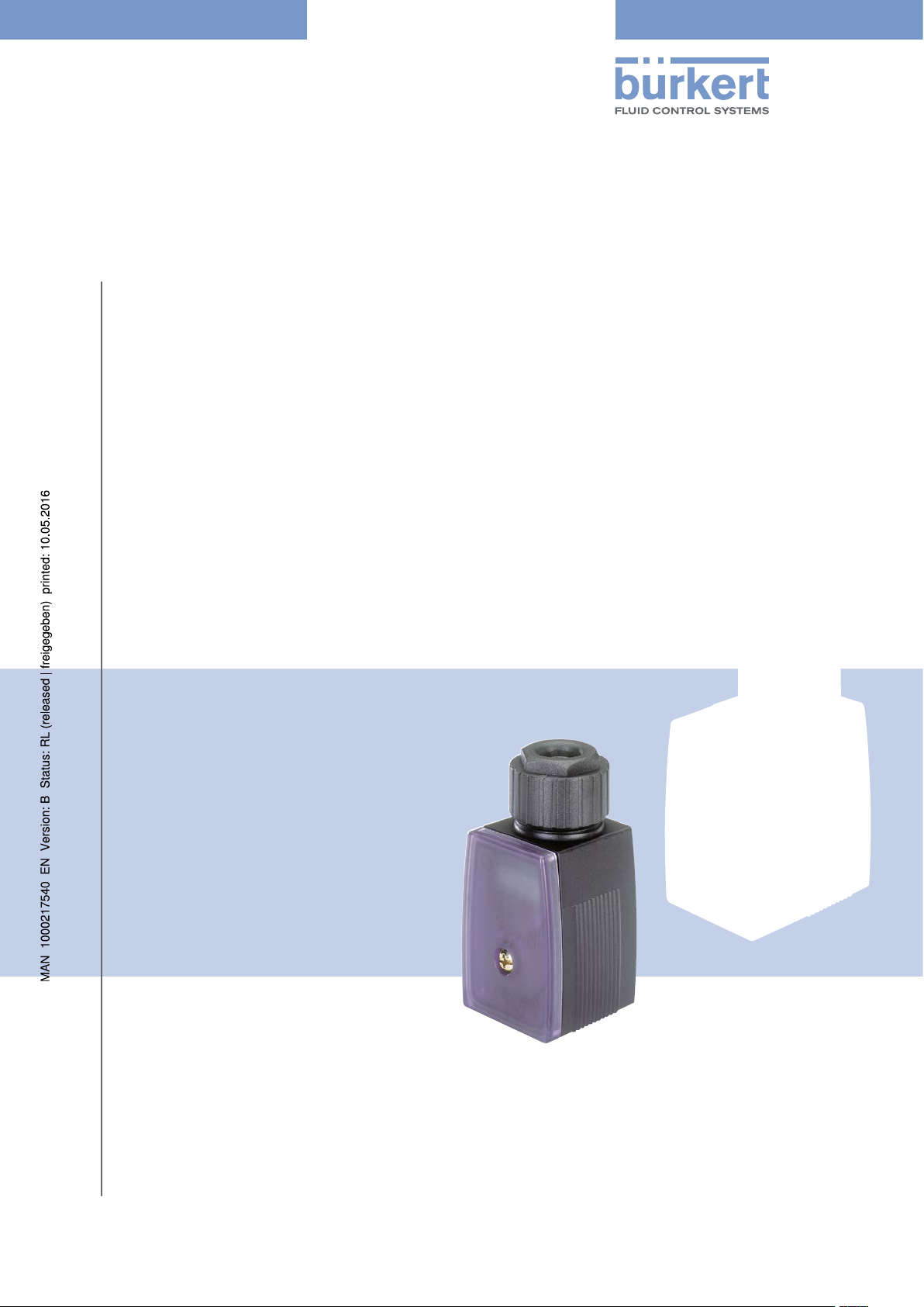
Type 8022
Flow Transmitter / Pulse divider
Durchflusstransmitter / Impulsteiler
Transmetteur de débit / Diviseur d’impulsions
Operating Instructions (from device Version 2)
Bedienungsanleitung (ab Geräte-Version 2)
Manuel d‘utilisation (à partir de la version 2 de l'appareil)
Page 2

We reserve the right to make technical changes without notice.
Technische Änderungen vorbehalten.
Sous réserve de modifications techniques.
© Bürkert SAS, 2011-2016
Operating Instructions 1603/03_EU-ML 00809506 Original FR
Page 3

Type 8022
1 OPERATING INSTRUCTIONS ........................................................................................................................................................3
1.1 Symbols used ..........................................................................................................................................................................3
1.2 Definition of the term "device" ........................................................................................................................................3
2 INTENDED USE ....................................................................................................................................................................................4
3 BASIC SAFETY INSTRUCTIONS .................................................................................................................................................5
4 GENERAL INFORMATION ................................................................................................................................................................6
4.1 Manufacturer’s address and international contact addresses ......................................................................6
4.2 Warranty conditions ..............................................................................................................................................................6
4.3 Information on the Internet ...............................................................................................................................................6
5 DESCRIPTION .......................................................................................................................................................................................7
5.1 General description ..............................................................................................................................................................7
5.2 Combined sensor ..................................................................................................................................................................7
5.3 Description of the name plate ........................................................................................................................................7
6 TECHNICAL DATA ................................................................................................................................................................................8
6.1 Conformity to standards and directives ....................................................................................................................8
6.2 Operating conditions ...........................................................................................................................................................8
6.3 Mechanical data ......................................................................................................................................................................8
6.4 Electrical data ..........................................................................................................................................................................9
7 ASSEMBLY, INSTALLATION ........................................................................................................................................................10
7.1 Assembly of the device ...................................................................................................................................................10
7.2 Electrical wiring ....................................................................................................................................................................11
7.2.1 Connection as a flow transmitter ....................................................................................................11
7.2.2 Connection as a pulse divider .........................................................................................................12
8 COMMISSIONING ............................................................................................................................................................................12
9 ADJUSTMENT .....................................................................................................................................................................................13
9.1 Display and control keys .................................................................................................................................................13
9.2 Control key functions ........................................................................................................................................................13
9.3 Operation as a flow transmitter ..................................................................................................................................14
English
1
Page 4

Type 8022
9.4 Operation as a pulse divider .........................................................................................................................................14
9.5 Operating levels ...................................................................................................................................................................14
9.5.1 Switching between the operating levels ......................................................................................15
9.6 Main menu of the configuration level ......................................................................................................................16
9.6.1 Unit – Setting the unit for the flow rate ....................................................................................16
9.6.2 InP (Input) – Entering the K factor of the fitting or selecting a preset K factor ...........17
9.6.3 Out (Output) – Setting the output signal ............................................................................19
9.6.4 dAtA (Data) – Uploading and downloading the device settings ....................................20
10 MAINTENANCE, TROUBLESHOOTING .................................................................................................................................21
10.1 Maintenance work ..............................................................................................................................................................21
10.2 Error messages ...................................................................................................................................................................21
10.3 Default values .......................................................................................................................................................................21
11 SPARE PARTS / ACCESSORIES .............................................................................................................................................22
12 PACKAGING AND TRANSPORT ...............................................................................................................................................22
13 STORAGE ..............................................................................................................................................................................................22
14 DISPOSAL ............................................................................................................................................................................................22
2
English
Page 5
Type 8022
Operating Instructions
1 OPERATING INSTRUCTIONS
The Operating Instructions describe the entire life cycle of the device. Keep these instructions in a location which is
easily accessible to every user, and make these instructions available to every new owner of the device.
The Operating Instructions manual contains important safety information.
Read the complete Operating Instructions. Pay special attention to the chapters Basic Safety Instructions and
Intended Use.
▶ Read the complete Operating Instructions.
1.1 Symbols used
Caution!
Warns of a possible danger!
▶ Failure to observe this warning may result in a moderate or minor injury.
notE
Warns of damage to property!
▶ Failure to observe the warning may result in damage to the device or the equipment.
Indicates important additional information, tips and recommendations.
refers to information in these Operating Instructions or in other documentation.
▶ Indicates an instruction to be carried out to avoid a danger, a warning or a possible risk.
→ Indicates a procedure to be carried out.
Indicates the result of a specific instruction.
1.2 Definition of the term "device"
In these Operating Instructions, the term "device" always refers to the flow transmitter type 8022 or the pulse
divider type 8022.
English
3
Page 6

Type 8022
Intended Use
2 INTENDED USE
Use of this device that does not comply with the Operating Instructions could present risks to people,
nearby installations and the environment.
The flow transmitter type 8022, associated to a Bürkert flow sensor, converts the frequency signal generated by the flow sensor into an analogue 4-20 mA current signal.
The pulse divider type 8022, associated to a Bürkert flow sensor, converts the frequency signal generated by the flow sensor into an adjustable frequency signal.
▶ The device is designed for use in industrial environments.
▶ Use the device in compliance with the characteristics and commissioning and use conditions specified in the
contractual documents and in the Operating Instructions.
▶ Do not use the device for security applications.
▶ Do not use the device outdoors.
▶ Protect the device against electromagnetic interference and ultraviolet rays.
▶ Use the device only if in perfect working order.
▶ Requirements for the safe and proper operation of the device are proper transport, storage and installation, as
well as careful operation and maintenance.
▶ Only use the device as intended.
4
English
Page 7
Type 8022
Basic Safety Instructions
3 BASIC SAFETY INSTRUCTIONS
These safety instructions do not make allowance for any
• contingencies and events which may arise during the installation, operation and maintenance of the devices.
• local safety regulations – the operator is responsible for observing these regulations, also with reference to the
installation personnel.
Various dangerous situations
To avoid injury take care:
▶ not to use the device in explosive atmospheres.
▶ not to use the device in an environment incompatible with the materials it is made of.
▶ not to subject the device to mechanical loads (e.g. by placing objects on top of it or by using it as a step).
▶ not to make any modifications to the device.
▶ to prevent any unintentional power supply switch-on.
▶ to ensure that installation and maintenance work are carried out by qualified, authorised personnel in posses-
sion of the appropriate tools.
▶ to guarantee a defined or controlled restarting of the process, after a power supply interruption.
▶ to observe the general technical rules when installing and using the device.
notE
Electrostatic sensitive components/modules!
The device contains electronic components, which react sensitively to electrostatic discharge (ESD). Contact
with electrostatically charged persons or objects is hazardous to these components. In the worst case scenario,
they will be destroyed immediately or will fail after start-up.
▶ Observe the requirements in accordance with EN 61340-5-1 to minimize and even avoid the possibility of
damage caused by a sudden electrostatic discharge!
▶ Also, ensure that you do not touch electronic components when the power supply voltage is present!
English
5
Page 8

Type 8022
General Information
4 GENERAL INFORMATION
4.1 Manufacturer’s address and international contact
addresses
To contact the manufacturer of the device, use following address:
Bürkert SAS
Rue du Giessen
BP 21
F-67220 TRIEMBACH-AU-VAL
You may also contact your local Bürkert sales office.
The addresses of our international sales offices are available on the internet at: www.burkert.com
4.2 Warranty conditions
The condition governing the legal warranty is the conforming use of the device in observance of the operating conditions specified in this manual.
4.3 Information on the Internet
The Operating Instructions and data sheets for type 8022 can be found on the Internet at: www.burkert.com
6
English
Page 9
12
1112 10 9
3 54
Type 8022
Description
5 DESCRIPTION
5.1 General description
The device, when it is combined with a flow sensor, operates either as a flow transmitter thanks to a 4-20 mA current
output, or as a pulse divider thanks to a transistor output. By default, the device operates as a flow transmitter.
• When operating as a flow transmitter, the 8022 converts the frequency signal generated by the combined
Bürkert flow sensor into an analogue 4-20 mA current signal (2-wire connection).
• When operating as a pulse divider, the 8022 converts the frequency signal generated by the combined Bürkert
flow sensor into an adjustable frequency signal (3-wire connection).
The device may be fitted with a display and configuration unit. The display and configuration unit makes it possible to:
• change the operating mode into pulse divider.
• configure the device.
5.2 Combined sensor
• The flow transmitter type 8022 must be combined to a Bürkert flow sensor with a transistor output, in the Low
Power version of the following types: 8020, 8030, 8070, SE30.
• The pulse divider type 8022 must be combined to a Bürkert flow sensor with a transistor output of the types
8020, 8030, 8070, SE30.
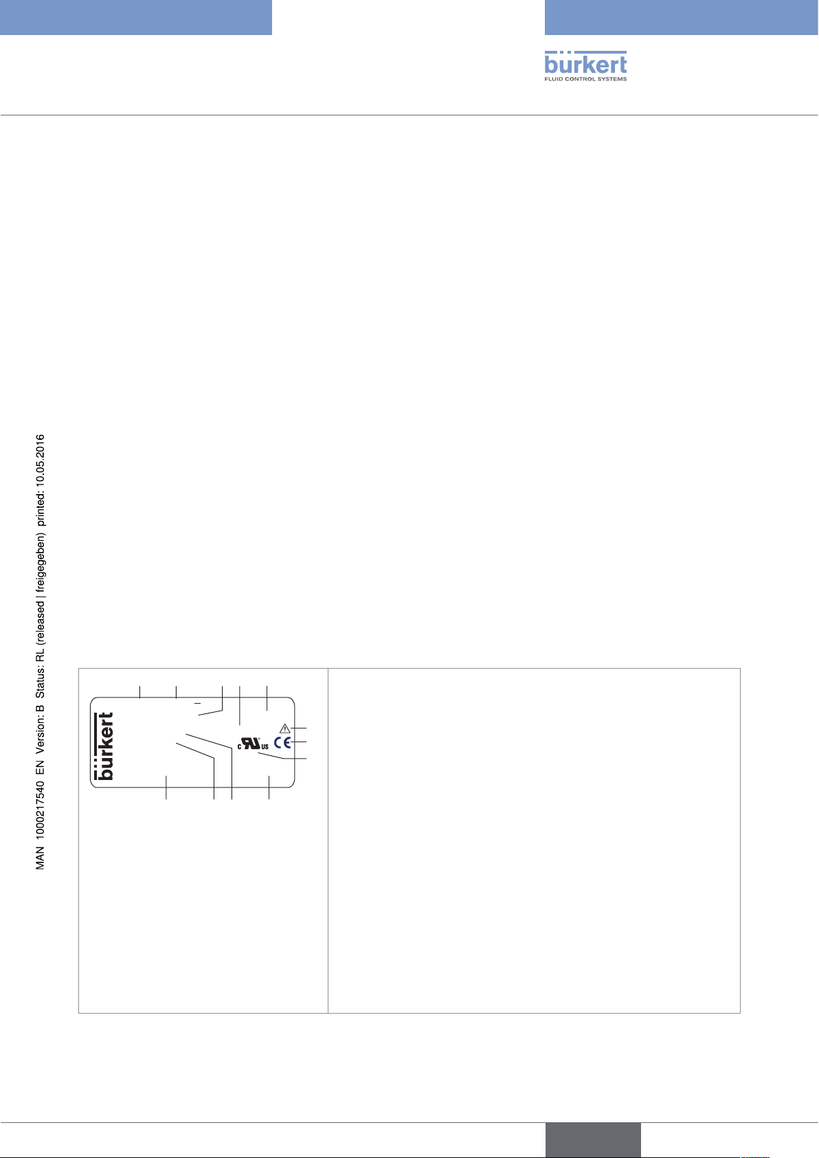
5.3 Description of the name plate
1. Type of the device
8022 12-30V...
4-20mA/Pulse Vers. 2
Tamb -10°...+60°C Pmax. 3.2W
S-N:2000
00563223 W49MG
Made in France
2. Operating voltage
6
3. Available outputs
7
8
4. Maximum power consumption
5. Version of the device
6. Warning: Before using the device, take into account the technical
specifications described in these Operating Instructions
7. Conformity
8. Certification
Fig. 1 : Example of a 8022 name plate
9. Construction code
10. Ambient operating temperature
11. Serial number
12. Order code
7
English
Page 10

Type 8022
Technical Data
6 TECHNICAL DATA
6.1 Conformity to standards and directives
The device conforms to the CE directives through the following standards:
• EMC: EN 61000-6-1, EN 61000-6-3
The UL devices (identified by the logo
lowing standards:
• UL 61010-1
• CAN/CSA-C22.2 n° 61010-1
), for the United States and Canada, also comply with the fol-
6.2 Operating conditions
Ambient temperature (operating) -10...+60 °C
Protection class IP65 according to EN 60529, if the following conditions are respected:
• Cable gland wired or blanked-off, or female connector plugged-in and
tightened
• Nut of the cable gland tightened with a torque of 1 N·m ± 20 %
(0,74 lbf·ft ± 20 %).
• Housing closed and screw tightened with a torque of 0,3 N·m ± 20 %
(0,22 lbf·ft ± 20 %), or display and configuration unit plugged on
the device and screw tightened with a torque of 0,3 N·m ± 20 %
(0,22 lbf·ft ± 20 %) at the factory.
Combined flow sensor
• Flow transmitter
• Bürkert flow sensor with a transistor output, in the Low Power version of
the types 8020, 8030, 8070, SE30.
• Pulse divider
• Bürkert flow sensor with a transistor output, of the types 8020, 8030,
8070, SE30.
6.3 Mechanical data
Fastening
• device without display and configuration unit
• device with display and configuration unit
Housing material polyamide/polycarbonate
Material of the seals
• seal for the sensor fixed connector
• seal for the cover
8
English
• 1 M3 x 35 screw
• 1 M3 x 45 screw
• NBR
• EPDM
Page 11

Type 8022
Technical Data
6.4 Electrical data
Electrical connection
• 4-pin terminal strip, 1.5 mm
2
max. wire section, 6 - 7 mm
cable diameter
• M12 male fixed connector
Voltage supply, 12...+30 V DC • filtered and regulated
• SELV circuit at a non dangerous energy level
• tolerance : ±10%
• residual ripple : < 5%
Frequency input 1-600 Hz, sensor supply voltage approximately V+ - 1 V
4-20 mA output
• Uncertainty of the output value
• Min. voltage drop at the device terminals
• Loop impedance
• ±1,5% of the full scale
• < 10 V at 20 mA
• max. 100 W at 12 VDC, max. 700 W at 24 VDC, max. 1000 W
at 30 VDC
Transistor output
• Uncertainty of the output value
NPN or PNP, 50 mA max. current, frequency up to 600 Hz
• ±1% of the measured value
Maximum power consumption
• Operating as a flow transmitter (4-20 mA
• 0,6 W
output in a 2-wire system)
• Operating as a pulse divider (NPN/PNP
output in a 3-wire system)
• 3,2 W, from which
- 0,2 W for the device,
- max. 1,5 W for the flow sensor,
- max. 1,5 W for the NPN/PNP output
English
9
Page 12

Type 8022
Assembly, Installation
7 ASSEMBLY, INSTALLATION
7.1 Assembly of the device
Fig. 1 shows how the device is screwed to the sensor.
notE
For the fault-free operation of the device observe the following during installation:
▶ When screwing to the sensor, ensure the seal is seated correctly.
▶ Torque the screw to a value between 0.2 and 0.3 N·m (between 0,15 and 0,22 lbf·ft), in order not to damage
the housing. With a damaged housing, correct operation of the device cannot be guaranteed.
10
Fig. 2 : Installing the device on the sensor
English
Page 13

Type 8022
Assembly, Installation
7.2 Electrical wiring
The electrical connection of the device is made on a terminal strip via cable gland, or an M12 male fixed connector.
Terminal assignment
NPN
1
PNP
2
12 - 30 V DC
3
GND
4
Fig. 3 : Terminal assignment of a version with cable gland
Pin assignment
12 - 30 V DC
1
NPN
2
GND
3
PNP
4
Fig. 4 : Pin assignment of the M12 male fixed connector
→ Wire:
• either the current output for an operation as a flow transmitter,
• or the transistor output for an operation as a pulse divider.
7.2.1 Connection as a flow transmitter
For an operation as a flow transmitter, wire the 4-20 mA current output with 2 wires, as described in Fig. 5.
8022
12 - 30 V DC
12 - 30 V DC
GND
Fig. 5 : Connection of the 4-20 mA current output of the flow transmitter
4 - 20 mA
11
English
Page 14

Type 8022
Assembly, Installation
7.2.2 Connection as a pulse divider
For an operation as a pulse divider, wire the transistor output with 3 wires, as described in Fig. 6.
The transistor output can be wired in NPN or in PNP mode with 3 wires.
Connection in NPN mode
Connection in NPN mode
12 - 30 V DC
NPN
GND
12 - 30 V DC
PNP
8022
8022
e.g. PLC
V+
IN
GND
e.g. PLC
V+
IN
12
GND
Fig. 6 : Connection of the transistor output of the pulse divider
8 COMMISSIONING
notE
▶ Only power on the device when the cover is closed.
▶ Switch off the device before removing the display and configuration unit.
GND
English
Page 15

Type 8022
Adjustment
9 ADJUSTMENT
9.1 Display and control keys
notE
The device is not tight when the display and configuration unit is removed.
▶ Screw the cover with order code 670549 on the device as soon as the display and configuration unit is
removed.
The display and configuration unit is only required to indicate the flow rate or to configure the device. It
can be removed after the settings have been made if you do not want to display the measured flow rate.
Status display:
with check mark = active
without check mark = not active
Process Value
Control keys:
selection, input and confirmation
(see chapter 9.2 Control key
Fig. 7 : Display and control keys
functions)
K factor
Keys for
LC display
Unit of flow rate
Unit of output value
Upper/Lower limit (High/Low)
4-character display
9.2 Control key functions
Their function with regards to the operating level is described in the following table.
Operating level
(see chapter 9.5
Operating levels)
Level 1:
Read level
Switching over the display value from:
• PV ProcessValue in set flow rate unit
Press and hold for 3 s:
Change to the configuration level
• PV ProcessValue in mA
• PV ProcessValue in Hz (frequency of sensor)
Level 2:
Configuration
level
Tab. 1 : Control keys
Scroll up (select). Scroll down (select). Confirm parameter, change between
Increase numerical
value by one value.
Enter values
Change by one
position to the left.
parameters.
Select and deselect parameter, confirm set
values.
Change to Read level when End is shown
13
English
Page 16

Type 8022
Adjustment
9.3 Operation as a flow transmitter
When operating as a flow transmitter, the frequency value of the sensor is converted into a 4-20 mA signal.
Setting:
→ Set the K factor of the fitting used (see Operating Instructions of the fitting used).
→ Always set the K factor in the pulse/liter unit.
→ Associate the 4-20 mA signal with a flow rate range using the upper and lower limits.
9.4 Operation as a pulse divider
When operating as a pulse divider, a pulse is sent out on the transistor output each time the set volume has been
counted.
The frequency value of the sensor is converted via the K factor and the volume set for a pulse.
Setting:
→ Set the K factor of the fitting used (see Operating Instructions of the fitting used).
→ Set the volume for each pulse sent out on the NPN and PNP outputs.
The K factor is always set in the unit pulse/liter whatever the setting in the parameter Unit.
9.5 Operating levels
For operating the flow transmitter / pulse divider there are 2 levels available: the Read level and the configuration level.
Level 1: Read level
When the device is switched on, it is at the Read level. The flow rate measured by the connected sensor is indicated.
At this level use the arrow keys to successively read different values and define which of them stays displayed. The
values differ depending whether the device is operating as a flow transmitter or a pulse divider.
Flow transmitter Pulse divider
l / m
PV
25.5
PV Hz
25.5
PV mA
12.3
Flow rate in liters/minute
Input frequency of the flow rate
sensor [Hz]
Output current [mA]
l / m
PV
Flow rate in liters/minute
25.5
PV Hz
25.5
Input frequency of the flow rate
sensor [Hz]
14
Fig. 8 : Level 1: Display options when operating as a flow transmitter or a pulse divider
English
Page 17

Type 8022
Adjustment
Level 2: Configuration level
At this level, the settings for the device are made.
Unit = set the unit for the flow rate
InP / Input = set the K factor of the fitting used
Out / Output = set the output signal
dAtA / Data = transfer of data from/to display and configuration unit
End = end configuration
Go back to Read level
Fig. 9 : Level 2: Define the settings
9.5.1 Switching between the operating levels
When the device is switched on, it is at the Read level.
→ Press and hold the ENTER key (3 seconds) to switch to the configuration level.
→ Confirm End in the main menu loop using the ENTER key to return to the Read level.
Level 2: Configuration levelLevel 1: Read level
l / m
PV
> 3 s (long)
25.5
Hz
mA
Unit
InP
Out
dAtA
End
Fig. 10 : Switching between the operating levels
15
English
Page 18

Type 8022
Adjustment
9.6 Main menu of the configuration level
→ Press and hold the ENTER key (3 s) to access the configuration level.
The following settings are possible:
Unit = set the unit for the flow rate, see chapter 9.6.1
InP / Input = set the K factor of the fitting used, see chapter 9.6.2
Out / Output = set the output signal, see chapter 9.6.3
dAtA / Data = transfer of data from/to the display and configuration unit, see chapter 9.6.4
Leaving the configuration level:
End = end the settings and go back to the Read level by pressing the ENTER key when End is
displayed.
9.6.1 Unit – Setting the unit for the flow rate
In this parameter, set the unit the measured flow rate is displayed in and in which the limits of the flow rate range
associated to the 4-20 mA output are defined.
When changing the unit (e.g. from liters to gallons), also change the current output limits.
Setting in the parameter:
16
l / s
l / m
l / h
m3 / m
m3 / h
g / s
g / m
g / s
End
Liters/second
Liters/minute
Liters/hour
Cubic meters/minute
Cubic meters/hour
US gallons/second
US gallons/minute
US gallons/hour
Status display changes to "active".
The selected unit is shown on the
display.
Fig. 11 : Unit – Setting the display for the flow rate unit
English
Page 19

Type 8022
Adjustment
9.6.2 InP (Input) – Entering the K factor of the fitting or selecting
a preset K factor
Entering the value of the K factor:
→ Go to the InP parameter and confirm.
→ Go to the FrEE parameter and confirm.
→ Enter the K factor of the fitting used, in pulses/liter. Refer to the Operating Instructions of the fitting used for
the value of the K factor (for example type S020, S030, S070 or S077).
→ Confirm the set K factor: the device uses the entered K factor.
Selecting a preset K factor (available from “Version 2” of the device. Refer to the name plate):
The K factor values of the fittings S020, S030, S070 and S077 are preset in the device.
If you use Instructions for selecting the correct preset K factor
• a fitting type S020 with a sensor
type 8020
→ Go to the InP parameter and confirm.
→ Go to the menu 8020 and confirm.
• a fitting type S030 with a sensor
type 8030 or SE30
• a fitting type S070 or a fitting type
S077, with a sensor type SE30
→ Go to the fitting model, for example SAdd if you use a saddle, and
confirm.
→ Go to the material the fitting is made of and confirm.
→ Go to the DN of the fitting. Confirm: the preset K factor is displayed.
Check that the displayed K factor is the same as the one indicated in
the Operating Instructions of the fitting used.
→ Confirm. The status display changes to “active”.
The preset K factor is used by the device.
→ Go to the InP parameter and confirm.
→ Go to the menu 8030 and confirm.
→ Go to the material the fitting is made of and confirm.
→ Go to the DN of the fitting. Confirm: the preset K factor is displayed.
Check that the displayed K factor is the same as the one indicated in
the Operating Instructions of the fitting used.
→ Confirm. The status display changes to “active”.
The preset K factor is used by the device.
→ Go to the InP parameter and confirm.
→ Go to the menu 8070 and confirm.
→ Go to the DN of the fitting. Confirm: the preset K factor is displayed.
Check that the displayed K factor is the same as the one indicated in
the Operating Instructions of the fitting used.
→ Confirm. The status display changes to “active”.
The preset K factor is used by the device.
English
17
Page 20

Type 8022
Adjustment
Parameters available from a “Version 2” of the device. Refer to the name plate of the device.
Enter the K factor *
Order of value input:
1. Select the decimal point place (each time
the key is pressed: one position to the left)
2. Set numerical values
K factor, see Operating instructions of the fitting used
If you use a fitting
*
S020 (with a
sensor 8020)
Select fitting model
T-fitting
If you use a
fitting S030
(with a sensor
8030 or SE30)
If you use a fitting
S070 or S077
(with a sensor
8070 or SE30)
Saddle
Welding tab or fusion spigot
Screw-on
Select material
Metal (stainless steel or brass)
PVC
PP
PVDF
Select fitting diameter **
DN06
** The display depends on the selected
sensor.
18
DN400
K factor is shown
KF
Status display
changes to „active“
Fig. 12 : Input – Setting the K factor
English
Page 21

Type 8022
Adjustment
9.6.3 Out (Output) – Setting the output signal
In this parameter, define whether the device is to work as a flow transmitter or a pulse divider.
Setting as flow transmitter (4 - 20 mA):
When changing the unit (e.g. from liters to gallons) the limit values for the current output are not converted automatically
→ Set the lower and upper limit values for the flow rate range associated to the 4-20 mA output, in the unit set
within the UNIT parameter.
The lower limit value is marked by an L (low) on the display and the upper limit value by an H (high).
Setting as pulse divider (Freq):
→ Set the volume, in the displayed unit, for each pulse emitted on the NPN and PNP outputs.
Setting in the parameter:
Status display changes to "active"
Select
Set the flow rate range *
flow
transmitter
mA
Lower limit value Upper limit value
L = low H = high
Select
pulse divider
Set the volume pro pulse, in the displayed unit *
L
* Order of value input:
1. Select the decimal point place
(each time the key is pressed: one position to
the left)
2. Set numerical values
Fig. 13 : Out – Setting the output; operation as flow transmitter or pulse divider
19
English
Page 22

Type 8022
Adjustment
9.6.4 dAtA (Data) – Uploading and downloading the device
settings
This function is available from the "Version 2" of the device. Refer to the name plate of the device.
The parameter makes it possible to transfer the device settings from one device to another by means of the display
and configuration unit.
Access the parameter:
Transfer from the device
to the display and configuration unit
Cancel
rdy = data has been
Confirm
Transfer from the display
and configuration unit to
the device
Fig. 14 : Data – Transfer of data from/to display and configuration unit
Upload (uPLd):
When uploading, the device settings are transferred to the display and configuration unit.
After the data has been transferred, "ready" (rdy) is displayed.
If the data could not be transferred to the display and configuration unit, the error message “Err” is displayed.
Download (dnLd):
When downloading, the device settings previously uploaded in the display and configuration unit are transferred
to another device type 8022.
After the data has been transferred, "ready" (rdy) is indicated on the display.
If the data could not be transferred to the device type 8022, the error message “Err” is displayed.
transferred
or
Err = data transfer not
possible
20
English
Page 23

Type 8022
Maintenance, Troubleshooting
10 MAINTENANCE, TROUBLESHOOTING
10.1 Maintenance work
The device is maintenance-free when operated according to these Operating Instructions.
10.2 Error messages
Error messages are only displayed at the Read level. They are shown alternately (flashing) with the process value.
Error Cause Troubleshooting
ERR1 Value cannot be displayed
(e.g. value too high).
ERR2 Input frequency of sensor higher than 600 Hz. • Use a suitable sensor.
ERR3 Calculated output current not within range of
4-20 mA or K factor = 0.
• Change the fow rate unit
(see chapter 9.6.1 Unit – Setting the unit for
the flow rate).
• Correctly set the flow rate range associated to
the 4-20 mA current output.
ERR4 Limit values of the flow rate range associated to
the 4-20 mA current output not correct (Low >
High).
ERR5 The K factor times the set volume (converted in
liters) pro pulse is < 1.
Tab. 2 : Error messages
10.3 Default values
Upon delivery, the following default values are saved:
Parameter Value
Unit
K factor (of fitting used)
Volume pro pulse 1 liter
Output signal (OUT) 4-20 mA
Lower flow rate limit
Upper flow rate limit
Liters/second [l/s]
1 pulse/liter [imp/l]
0 liters/second [l/s]
250 liters/second [l/s]
• Use a different sensor and/or correctly set the
K factor of the fitting used.
Correctly set the values.
• Check the set K factor.
• If the K factor is correct, enter a higher volume
pro pulse so that the K factor times the set
volume (converted in liters) pro pulse is equal
to or higher than 1.
Tab. 3 : Default values
21
English
Page 24

Type 8022
Spare parts / Accessories
11 SPARE PARTS / ACCESSORIES
Spare part /accessory Order code
Display and configuration unit
Transparent cover, with screw and seal (for operating without display and configuration
unit)
4-pin M12 female right-angle connector
4-pin M12 female connector moulded on 5-m long cable
Tab. 4 : Ordering table of spare parts and accessories
562 876
670 549
784 301
918 038
12 PACKAGING AND TRANSPORT
notE
Transport damage!
Inadequately protected equipment may be damaged during transport.
• During transportation protect the device against moisture and dirt in shock-resistant packaging.
• Do not allow the temperature to exceed or drop below the permitted storage temperature.
13 STORAGE
notE
Incorrect storage may damage the device.
• Store the device in a dry and dust-free location!
• Storage temperature. -20 … 65 °C.
14 DISPOSAL
22
→ Dispose of the device and packaging in an environmentally friendly manner.
Observe national waste disposal regulations.
English
Page 25

Type 8022
English
23
Page 26

Type 8022
Spare parts / Accessories
24
English
Page 27

Page 28

www.burkert.com
 Loading...