

Page 1

We reserve the right to make
Type 8020
Flowmeter with paddle wheel
Operating Instructions
Bedienungsanleitung
Manuel d'utilisation
2
1. ABOUT THIS MANUAL ...........................................................3
2. INTENDED USE ..........................................................................5
3. BASIC SAFETY INFORMATION .........................................6
4. GENERAL INFORMATION .....................................................9
5. DESCRIPTION .......................................................................... 10
6. TECHNICAL DATA .................................................................. 13
7. INSTALLATION AND COMMISSIONING ..................... 22
8. MAINTENANCE ........................................................................ 35
9. ACCESSORIES ........................................................................ 38
10. PACKAGING, TRANSPORT ............................................... 39
11. STORAGE ................................................................................... 39
12. DISPOSAL OF THE DEVICE .............................................40
English
3
1. ABOUT THIS MANUAL
This manual describes the entire life cycle of the device.
Please keep this manual in a safe place, accessible to all
users and any new owners.
This manual contains important safety information.
Failure to comply with these instructions can lead to
hazardous situations.
• This manual must be read and understood.
Symbols used
danger
Warns against an imminent danger.
• Failure to observe this warning can result in death or in
serious injury.
Warning
Warns against a potentially dangerous situation.
• Failure to observe this warning can result in serious
injury or even death.
English
3
technical changes without notice.
Technische Änderungen
vorbehalten.
Sous réserve de modification
technique.
www.burkert.com
© 2013 Bürkert SAS
Operating Instructions
1302/0_EU-ml 00419607
Page 2
4
attention
Warns against a possible risk.
• Failure to observe this warning can result in substantial
or minor injuries.
note
Warns against material damage.
• Failure to observe this warning may result in damage
to the device or system.
Indicates additional information, advice or
important recommendations.
refers to information contained in this manual or in
other documents.
→ Indicates a procedure to be carried out.
Definition of the word "device"
The word "device" used within this manual always refers to
the flowmeter type 8020.
English
5
2. INTENDED USE
Use of the device that does not comply with the
instructions could present risks to people, nearby
installations and the environment.
• The 8020 flowmeter is intended exclusively to measure
the flow rate of liquids.
• This device must be protected against electromagnetic interference, ultraviolet rays and, when installed
outdoors, the effects of climatic conditions.
• This device must be used in compliance with the
characteristics and commissioning and use conditions
specified in the contractual documents and in the user
manual.
• Requirements for the safe and proper operation of the
device are proper transport, storage and installation,
as well as careful operation and maintenance.
• Only use the device as intended.
→ Observe any existing restraints when the device is
exported.
English
5
6
3. BASIC SAFETY INFORMATION
This safety information does not take into account:
• any contingencies or occurences that may arise during
installation, use and maintenance of the devices.
• the local safety regulations for which the operating company
is responsible including the staff in charge of installation
and maintenance.
Danger due to high pressure in the installation.
Danger due to electrical voltage.
Danger due to high temperatures of the fluid.
Danger due to the nature of the fluid.
Various dangerous situations
• Prevent any unintentional power supply switch-on.
• Ensure that installation and maintenance work are
carried out by qualified, authorised personnel in
possession of the appropriate tools.
English
7
Various dangerous situations
• Guarantee a set or controlled restarting of the process, after a power supply interruption.
• Use the device only if in perfect working order and in
compliance with the instructions provided in the operating instructions.
• Observe the general technical rules when installing
and using the device.
• Do not use this device in explosive atmospheres.
• Do not use the device for the measurement of gas flow
rates.
• Do not use fluid that is incompatible with the materials
the device is made of.
• Do not use this device in an environment incompatible
with the materials it is made of.
• Do not subject the device to mechanical loads (e.g. by
placing objects on top of it or by using it as a step).
• Do not make any external modifications to the device. Do
not paint any part of the device.
English
7
Page 3

8
note
The device may be damaged by the fluid in contact
with.
• Systematically check the chemical compatibility of the
component materials of the device and the fluids likely
to come into contact with it (for example: alcohols,
strong or concentrated acids, aldehydes, alkaline
compounds, esters, aliphatic compounds, ketones,
halogenated aromatics or hydrocarbons, oxidants and
chlorinated agents).
note
Elements / Components sensitive to electrostatic
discharges
• This device contains electronic components sensitive
to electrostatic discharges. They may be damaged
if they are touched by an electrostatically charged
person or object. In the worst case scenario, these
components are instantly destroyed or go out of order
as soon as they are activated.
• To minimise or even avoid all damage due to an electrostatic discharge, take all the precautions described
in the EN 61340-5-1 and 5-2 norms.
• Also ensure that you do not touch any of the live electrical components.
English
9
4. GENERAL INFORMATION
To contact the manufacturer of the device, use following
address:
Bürkert SAS
Rue du Giessen
BP 21
F-67220 TRIEMBACH-AU-VAL
The addresses of our international sales offices are
available on the internet at: www.burkert.com
Warranty conditions
The condition governing the legal warranty is the conforming
use of the device in observance of the operating conditions
specified in this manual.
Information on the Internet
You can find the user manuals and technical data sheets
regarding the type 8020 at: www.burkert.com
English
9
10
5. DESCRIPTION
Area of application
The 8020 flowmeter is intended to measure the flow rate of
neutral or slightly aggressive liquids free of solid particles.
Construction
The device is made up of an electronic module and of a flow
sensor. The device can be installed in any pipe from DN20
(except for DN20 specified p. 27) to DN400.
The device has, depending on the version, 1 NPN transistor output, 2 transitor outputs, NPN and PNP, or 1 sinus
output (coil output).
Electrical connection is made via a male fixed connector.
Measuring principle
The circulation of fluid within the pipe causes the paddle
wheel of the sensor to rotate. The flowmeter detects the
rotation of the paddle-wheel and generates a signal which
frequency f is proportional to the flow rate Q, using the
formula f = KxQ.
f = frequency in Hertz (Hz)
K = K factor of the S020 fitting used, in pulse/litre
Q = flow rate in litre/second
English
11
Description of the name plate
FLOW:8020-FKM-PVDF
HALL LONG 12-36VDC
OUT:OPENCOL.NPN/PNP
S-N:21219
419589 W48LG
Made in France
1 2 3
4
5
6
789
1. Quantity measured and type of the device
2. Material of the seal
3. Material of the flow sensor frame
4. Version of the flow sensor and, when required, power
supply
5. Output data
6. Conformity logo
7. Manufacturing code
8. Serial number
9. Order code
English
11
Page 4
12
Available versions of the
electronic module
The electrical connection of all the devices is made through
a male fixed connector.
Supply voltage
Output
Flow sensor
Order code
12-36 V DC
filtered and
regulated
2 transistors,
NPN and
PNP
Hall, short 419587
Hall, long
419589
energized via the
Bürkert transmitter
the flow sensor is
connected to
1 NPN
transistor
Hall Low
Power,
short
419591
Hall Low
Power, long
419593
without 1 sinus
output
Coil, short 419583
Coil, long 419585
English
13
6. TECHNICAL DATA
Operating conditions
Ambient temperature -15 °C to +60 °C
Air humidity < 80%, non condensated
Protection rating IP65 acc. to EN 60529, female
connector wired, plugged and
tightened
Conformity to standards and
directives
The device conforms to the EC directives through the following standards:
• EMC: EN 61000-6-2, EN 61000-6-3
• Vibration: EN 60068-2-6
• Shock: EN 60068-2-27
• Pressure: Article 3§3 of the Pressure Directive 97/23/CE.
English
13
14
Acc. to pressure directive 97/23/CE, the device can only
be used in the following cases (depending on the max.
pressure, the DN of the pipe and the fluid):
Type of fluid Conditions
Fluid group 1 § 1.3.a Only DN ≤ 25
Fluid group 2 § 1.3.a DN ≤ 32
or DN > 32 and PNxDN ≤ 1000
Fluid group 1 § 1.3.b DN ≤ 25
or DN > 25 and PNxDN ≤ 2000
Fluid group 2 § 1.3.b DN ≤ 400
General data
Tab. 1: Temperature-pressure dependency curves
10
9
8
7
6
5
4
3
2
1
0
-10 +10 +30 +50+70
PVDF
PVDF (PN10)
PVC (PN10)
PP (PN10)
PVC + PP
11
A
P (bar)
T (°C)
Metal
English
15
Pipe diameter DN20 (except for DN20 specified
p.27) to DN400. The appropriate
diameter is determined using the flow
rate / DN / fluid velocity graphs.
Pressure class
Depends on the material of the fitting
used and on the fluid temperature.
See Tab. 1
Fluid temperature
• with fitting S020 in
metal or PVDF
• with fitting S020
in PP
• with fitting S020 in
PVC
The fluid temperature may be restricted
by the fluid pressure: Refer to the
temperature-pressure dependency
curves for the device. See Tab. 1
• -15 to +80 °C
• 0 to +80 °C
• 0 to +50 °C
Flow rate measuring
range
Hall and Hall Low Power versions: 0,3
to 10 m/s
Sinus version: 0,5 to 10 m/s
Accuracy, with standard
K factor
≤ ±(0.5 % of the full scale + 2.5 % of
the measured value)*
Linearity ≤ ±0,5 % of the full scale*
Repeatability ±0,4 % of the measured value*
* Determined in the following reference conditions: medium =
water, water and ambient temperatures 20 °C, min. upstream and
English
15
Page 5

16
downstream distances respected, appropriate pipe dimensions
Tab. 2: Dimension H [mm] of the 8020 depending on
the DN of fitting S020
H
T fitting
Saddle
Spigot, in
plastic
Welding
tab with
radius, in
stainless
steel
DN20 153.5
DN25 153.5
DN32 157.0
DN40 161.0
DN50 167.0 191.5 162.5
DN65 167.0 190.5 172.5 167.0
DN80 194.5 177.5 173.0
DN100 199.5 184.0 183.5
English
17
H
T fitting
Saddle
Spigot, in
plastic
Welding
tab with
radius, in
stainless
steel
DN110 195.5
DN125 202.5 194.5
DN150 212.5 230.0 205.5
DN180 236.5
DN200 248.5 251.0 226.0
DN250 269.0 286.0
DN300 280.5 305.5
DN350 294.0 317.5
DN400 308.5
English
17
18
191 mm
153 mm
75 mm
Fig. 1: Dimensions [mm] of the flowmeter 8020
Materials
Part Material
Housing PE
Nut PC
Female connector type
2508 / screw / seal
PA / Stainless steel / NBR
Frame of the flow sensor
and paddle wheel
PVDF
English
19
Part Material
Axis and bearings Ceramic
Gasket FKM (EPDM optional)
Electrical data
Supply voltage
• Hall version
• Hall Low Power
version
• 12-36 V DC, filtered and
regulated
• 12-36 V DC, via transmitter the
device is connected to
Current
consumption
• Hall version
• Hall Low Power
version
• 50 mA max.
• 0,8 mA max.
Protection against
polarity reversal
yes
Protection against
spike voltages
yes
Protection against
short circuits
yes
English
19
Page 6

20
Transistor output
(Hall version)
pulse output, NPN and PNP, open
collector, max. 100 mA, frequency
up to 300 Hz, duty cycle 1/2 ±10%
NPN output: 0,2-36 V DC
PNP output: supply voltage
Transistor output
(Hall Low Power
version)
pulse output, NPN, open collector,
max. 10 mA, frequency up to
300 Hz, duty cycle 1/2 ±10%
Coil output sine-wave signal, frequency up to
300 Hz, about 2.8 mV peak-to-peak/
Hz under a 50 kW load
English
21
Electrical connection
Type of connector cable type
2508 female connector
(supplied), with order
code 438811
For the Hall and Hall Low
Power versions:
• shielded, max. 50 m
• 5 to 8 mm in diameter
• wires between 0,25 and
1,5 mm
2
in cross section
For the sinus version:
• shielded, max. 10 m
• 5 to 8 mm in diameter
• wires between 0,25 and
1,5 mm
2
in cross section
English
21
22
7. INSTALLATION AND
COMMISSIONING
Safety instructions
danger
Risk of injury due to high pressure in the installation.
• Stop the circulation of fluid, cut off the pressure and
drain the pipe before loosening the process connections.
Risk of injury due to high fluid temperatures.
• Use safety gloves to handle the device.
• Stop the circulation of fluid, and drain the pipe before
loosening the process connections.
Risk of injury due to the nature of the fluid.
• Respect the prevailing regulations on accident prevention
and safety relating to the use of hazardous products.
danger
Risk of injury due to electrical voltage.
• Shut down and isolate the electrical power source
before carrying out work on the system.
• Observe all applicable accident protection and safety
regulations for electrical equipment.
English
23
Warning
Risk of injury due to non-conforming installation.
• The electrical and fluid installation can only be carried out
by qualified and skilled staff with the appropriate tools.
• Observe mounting instructions of the fitting.
Risk of injury due to an uncontrolled restart.
• Ensure that the restart of the installation is controlled
after any interventions on it.
Warning
Risk of injury if the fluid pressure/ temperature
dependency is not respected.
• Take account of fluid temperature-pressure
dependancy according to the nature of the materials
the fitting is made of (see Tab. 1).
• Comply with the Pressure Directive 97/23/EC.
English
23
Page 7

24
Warning
Risk of injury due to non-conforming commissioning.
Non-conforming commissioning may lead to injuries and
damage the device and its surroundings.
• Before commissioning, make sure that the staff in
charge have read and fully understood the contents of
the manual.
• In particular, observe the safety recommendations and
intended use.
• The device / the installation must only be commissioned by suitably trained staff.
note
Risk of damage to the device due to the environment
• Protect this device against electromagnetic interference, ultraviolet rays and, when installed outdoors, the
effects of the climatic conditions.
To make sure the device operates correctly, plug in
and tighten the connector.
English
25
Installation of the fitting onto the
pipe
→ Choose a fitting appropriate to the velocity and the
flow rate of the fluid inside the pipe, refer to the graphs
at right (see Tab. 3). The graph is used to determine
the DN of the pipe and the fitting appropriate to the
application, according to the fluid velocity and the flow
rate.
→ Install the fitting on the pipe as described in the oper-
ating instructions of the fitting used.
English
25
26
Tab. 3: Diagram flow/ fluid velocity/ DN of S020 fitting
0.10.3 0.51 35 10
0.01
0.02
0.05
0.1
0.2
0.5
1
2
5
10
20
50
100
200
m
3
/h
0.2
0.5
1
2
5
10
20
50
100
200
500
1000
2000
3000
l/min
0.30.5 13510
30
m/s
fps
US gpm
0.05
0.1
0.2
0.5
1
2
5
10
20
50
100
200
500
1000
DN 65
DN 50 (DN65)*
DN 40 (DN50)*
DN 32 (DN40)*
DN 25 (DN32)*
DN 20 (DN25)*
500
1000
2000
2000
5000
10000
5000
20000
5000
10000
20000
30000
50000
100000
DN 400
DN 350
DN 300
DN 250
DN 200
DN 150
DN 125
DN 100
DN 80
Flow rate
Fluid velocity
Example
1)
English
27
Example:
• Specification:
- nominal flow: 10 m
3
/h,
- optimal flow velocity: between 2 and 3 m/s
• Solution: intersection between flow rate and flow velocity
in the graph gives the appropriate pipe diameter, DN40
(or DN50 for the asterisked fittings).
* For the fittings:
• with external thread connections acc. to SMS 1145,
• with welding end connections acc. to SMS 3008,
BS 4825 / ASME BPE or DIN 11850 Rg 2,
• Clamp connections acc. to SMS 3017/ ISO 2852, BS
4825 / ASME BPE or DIN 32676
1)
The device cannot be installed on the DN20 fittings listed
above.
English
27
Page 8
28
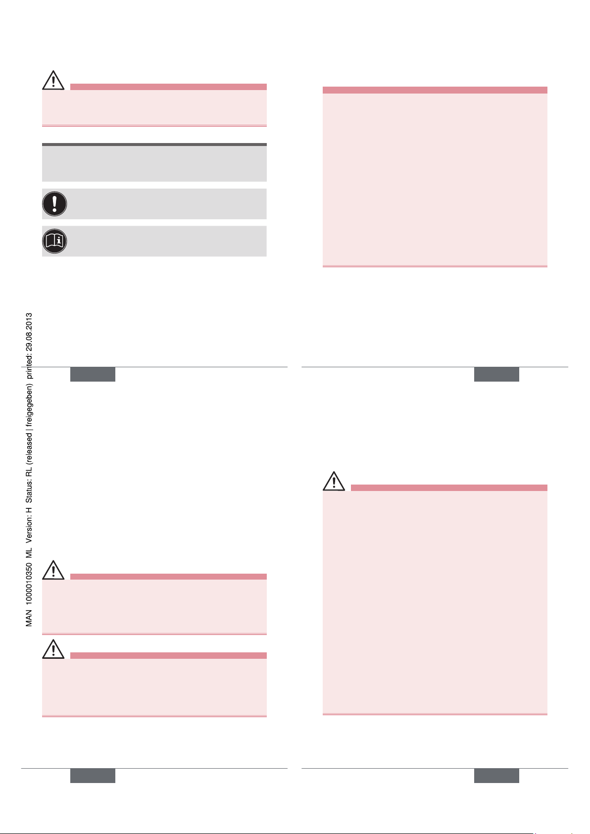
Installation of the 8020 on the
S020 fitting
→ Insert nut 3 on fitting 5.
→ Insert snap ring 2 into
groove 4.
→ Check that seal 6 is
correctly inserted on the
flow sensor.
→ Slowly insert device 1
into the fitting.
If the mounting is correctly
done the device cannot be
turned around anymore.
→ Hand lock the assembly
with nut 3.
1
2
3
4
5
6
Fig. 2: Installation of the flowmeter on the S020 fitting
English
29
Wiring
danger
Risk of injury due to electrical discharge
• Shut down and isolate the electrical power source
before carrying out work on the system.
• Observe all applicable accident protection and safety
regulations for electrical equipment.
Protect the power supply
• Protect the power supply with a correctly rated
fuse if it is not protected by default.
• Use a shielded cable with an operating temperature limit higher than +80 °C.
• Use a high quality electrical power supply (filtered and regulated).
• Do not install the cable near high voltage or high
frequency cables.
• If a closed installation cannot be avoided,
maintain a minimum distance of 30 cm.
English
29
30
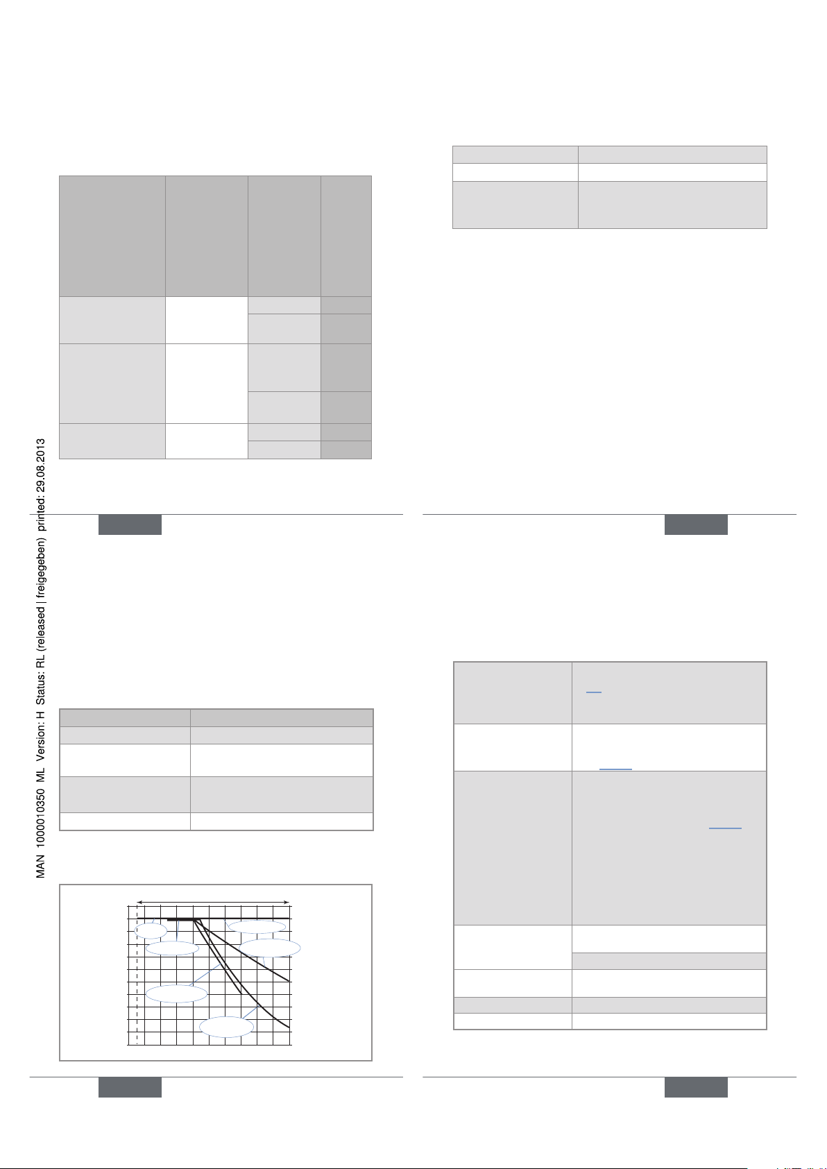
Assembling the female connector
1
2
3
4
→ Unscrew nut [1] of the cable gland.
→ Remove terminal block [3] from
housing [2].
→ Insert the cable into nut [1], through
seal [4], and into the cable gland and
finally through housing [2].
→ Connect the wires on terminal block
[3].
→ Position terminal block [3] in steps of
90° then put it back into housing [2],
pulling gently on the cable so that the
wires do not clutter the housing.
→ Tighten nut [1] of the cable gland.
6
5
→ Place seal [5] between the connector
and the fixed connector on the device
and then plug the 2508 connector into
the fixed connector.
→ Insert and then tighten screw [6] to
ensure tightness and correct electrical
contact.
Fig. 3: Assembling the female connector type 2508
(supplied)
English
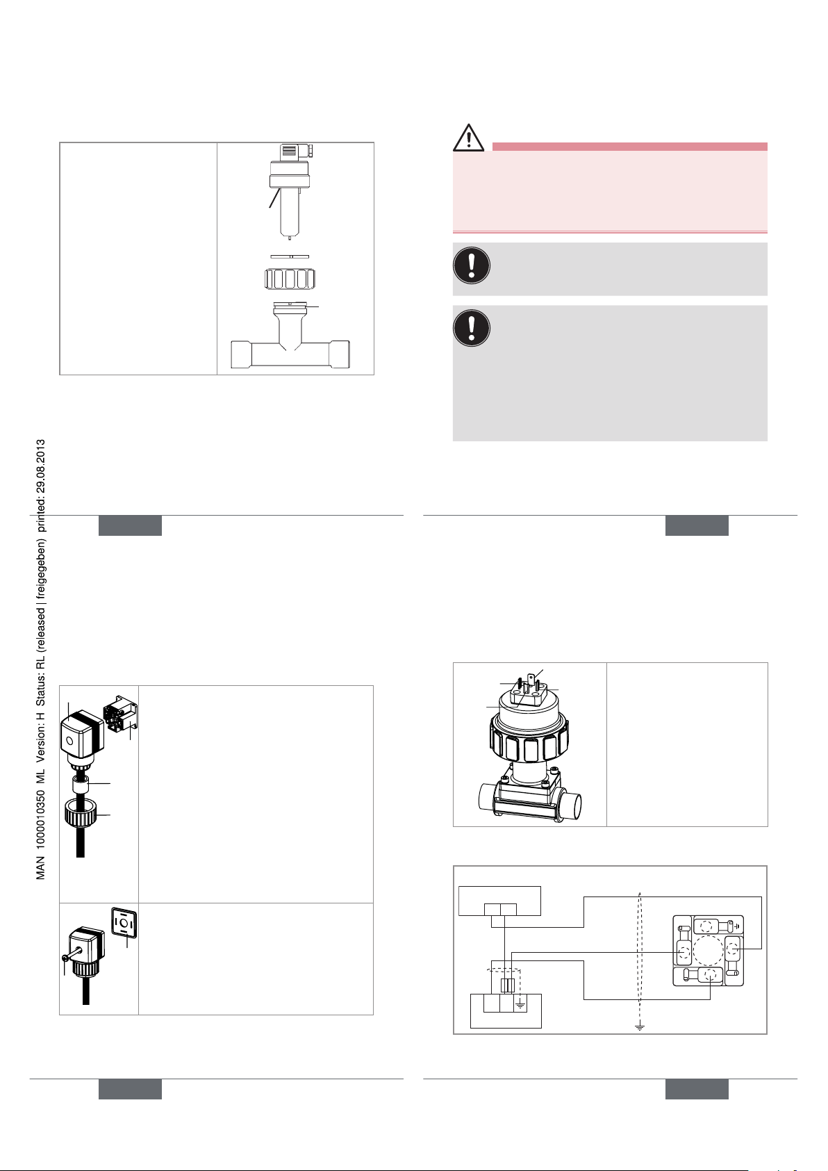
31
1
2
3
4
1 : V+ (12-36 V DC)
2 : NPN transistor output
3 : 0 V DC
4 : PNP transistor output
Fig. 4: Pin assignment of the fixed connector, Hall
version
12-36 V DC
+ -
+-
1
3
2
V+
0 V DC
Power supply
Terminal block of the 2508
Pulse input on external instrument
Fig. 5: NPN wiring of the Hall version
English
31
Page 9

32
12-36 V DC
+-
1
3
2
V+
0 V DC
+-
Pulse input on external instrument
Terminal block of the 2508
Power supply
Fig. 6: PNP wiring of the Hall version
1
2
3
4
1 : V+ (12-36 V DC)
2 : NPN transistor output
3 : 0 V DC
4 : Not connected
Fig. 7: Pin assignment of the fixed connector, Hall Low
Power version
English
33
1
3
2
+-
IN
Terminal block of the 2508
IN = pulse input on remote transmitter
Remote transmitter
Fig. 8: NPN wiring of the Hall Low Power version
1
2
3
4
1 : Not connected
2 : Sinus output
3 : Sinus output
4 : Not connected
Fig. 9: Pin assignment of the fixed connector, sinus
version
English
33
34
1
3
2
+-
IN
Terminal block of the 2508
IN = pulse input on remote transmitter
Remote transmitter
Fig. 10: Wiring of the sinus output of a sinus version
English
35
8. MAINTENANCE
Safety instructions
danger
Risk of injury due to electrical voltage.
• Shut down and isolate the electrical power source
before carrying out work on the system.
• Observe all applicable accident protection and safety
regulations for electrical equipment.
Risk of injury due to high pressure in the installation.
• Stop the circulation of fluid, cut off the pressure
and drain the pipe before loosening the process
connections.
Risk of injury due to high fluid temperatures.
• Use safety gloves to handle the device.
• Stop the circulation of fluid, and drain the pipe before
loosening the process connections.
• Keep all easily flammable material and fluid away from
the device.
English
35
Page 10

36
danger
Risk of injury due to the nature of the fluid.
• Respect the prevailing regulations on accident prevention and safety relating to the use of aggressive fluids.
Warning
Risk of injury due to non-conforming maintenance.
• Maintenance must only be carried out by qualified and
skilled staff with the appropriate tools.
• Ensure that the restart of the installation is controlled
after any interventions.
Cleaning
note
The device may be damaged by the cleaning liquid.
• Clean the device with a cloth slightly dampened with
water or a cleaning liquid compatible with the materials
the device is made of.
English
37
Cleaning the flow sensor
note
The flow sensor may be damaged by the cleaning
liquid.
• Use a cleaning product that is compatible with the
materials the flow sensor is made of.
• Do not use any abrasive acting materials.
note
After cleaning the flow sensor:
• Rinse the flow sensor.
• Check the seal and replace it if necessary.
English
37
38
9. ACCESSORIES
attention
Risk of injury and/or damage caused by the use of
unsuitable parts.
Incorrect accessories and unsuitable spare parts may
cause injuries and damage the device and the surrounding area.
• Use only original accessories and original spare parts
from Bürkert.
Accessories Order code
Female connector with cable gland (type
2508)
438811
Female connector (type 2509) with NPT
1/2’’ reduction, without cable gland
162673
Set with seals (1 FKM + 1 EPDM)
552111
English
39
10. PACKAGING, TRANSPORT
attention
Damage due to transport
Transport may damage an insufficiently protected device.
• Transport the device in shock-resistant packaging and
away from humidity and dirt.
• Do not expose the device to temperatures that may
exceed the admissible storage temperature range.
• Protect the electrical interfaces using protective plugs.
11. STORAGE
attention
Poor storage can damage the device.
• Store the device in a dry place away from dust.
• Storage temperature: -15 to +60°C.
English
39
Page 11

40
12. DISPOSAL OF THE DEVICE
→ Dispose of the device and its packaging in an environ-
mentally-friendly way.
note
Damage to the environment caused by products
contaminated by fluids.
• Keep to the existing provisions on the subject of waste
disposal and environmental protection.
Note
Comply with the national and/or local regulations
which concern the area of waste disposal.
English
Page 12

We reserve the right to make
Typ 8020
Durchfluss-Messgerät mit Flügelrad
Bedienungsanleitung
2
1. DIE BEDIENUNGSANLEITUNG .........................................3
2. BESTIMMUNGSGEMÄSSE VERWENDUNG................5
3. GRUNDLEGENDE SICHERHEITSHINWEISE ..............6
4. ALLGEMEINE HINWEISE .......................................................9
5. BESCHREIBUNG .................................................................... 10
6. TECHNISCHE DATEN ..........................................................13
7. INSTALLATION UND INBETRIEBNAHME .................. 22
8. WARTUNG ..................................................................................35
9. ZUBEHÖR .................................................................................. 38
10. VERPACKUNG, TRANSPORT ........................................... 39
11. LAGERUNG ................................................................................ 39
12. ENTSORGUNG DES GERÄTES ......................................40
deutsch
3
1. DIE BEDIENUNGSANLEITUNG
Die Bedienungsanleitung beschreibt den gesamten Lebenszyklus des Gerätes. Bewahren Sie diese Anleitung so auf,
dass sie für jeden Benutzer zugänglich ist und jedem neuen
Eigentümer des Gerätes wieder zur Verfügung steht.
Diese Bedienungsanleitung enthält wichtige Informationen zur Sicherheit!
Das Nichtbeachten dieser Hinweise kann zu gefährlichen
Situationen führen.
• Diese Bedienungsanleitung muss gelesen und verstanden werden.
Darstellungsmittel
Gefahr!
Warnt vor einer unmittelbaren Gefahr!
• Bei Nichteinhaltung sind Tod oder schwere Verletzungen die Folge.
WarnunG!
Warnt vor einer möglicherweise gefährlichen Situation!
• Bei Nichteinhaltung drohen schwere Verletzungen
oder Tod.
deutsch
technical changes without notice.
Technische Änderungen
vorbehalten.
Sous réserve de modification
technique.
www.burkert.com
© 2013 Bürkert SAS
Operating Instructions
1302/0_EU-ml 00419607
Page 13
4
VOrSIChT!
Warnt vor einer möglichen Gefährdung!
• Nichtbeachtung kann mittelschwere oder leichte Verletzungen zur Folge haben.
hInWeIS!
Warnt vor Sachschäden!
• Bei Nichtbeachtung kann das Gerät oder die Anlage
beschädigt werden.
bezeichnet wichtige Zusatzinformationen, Tipps
und Empfehlungen.
verweist auf Informationen in dieser Bedienungsanleitung oder in anderen Dokumentationen.
→ markiert einen Arbeitsschritt, den Sie ausführen
müssen.
Begriffsdefinition "Gerät"
Der in dieser Anleitung verwendete Begriff "Gerät" steht
immer für das Durchfluss-Messgerät Typ 8020.
deutsch
5
2. BESTIMMUNGSGEMÄSSE
VERWENDUNG
Bei nicht bestimmungsgemäßem Einsatz dieses
Gerätes können Gefahren für Personen, Anlagen in
der Umgebung und die Umwelt entstehen.
• Das Durchfluss-Messgerät 8020 ist ausschließlich für
die Durchflussmessung in Flüssigkeiten bestimmt.
• Schützen Sie das Gerät vor elektromagnetischen Störungen, U.V.-Bestrahlung und bei Außenanwendung
vor Witterungseinflüssen.
• Für den Einsatz sind die in den Vertragsdokumenten
und der Bedienungsanleitung spezifizierten zulässigen Daten, Betriebs- und Einsatzbedingungen zu
beachten.
• Zum sicheren und problemlosen Einsatz des Gerätes
müssen Transport, Lagerung und Installation ordnungsgemäß erfolgen, außerdem müssen Betrieb und
Wartung sorgfältig durchgeführt werden.
• Achten Sie immer darauf, dieses Gerät auf ordnungsgemäße Weise zu verwenden.
→ Beachten Sie bei der Ausfuhr des Gerätes gegebenen-
falls bestehende Beschränkungen.
deutsch
6
3. GRUNDLEGENDE
SICHERHEITSHINWEISE
Diese Sicherheitshinweise berücksichtigen keine
• Zufälligkeiten und Ereignisse, die bei Montage, Betrieb und
Wartung der Geräte auftreten können.
• Ortsbezogenen Sicherheitsbestimmungen, für deren
Einhaltung, auch in Bezug auf das Installations- und Wartungspersonal, der Betreiber verantwortlich ist.
Gefahr durch hohen Druck in der Anlage!
Gefahr durch elektrische Spannung!
Gefahr durch hohe Flüssigkeitstemperaturen!
Gefahr aufgrund der Art der Flüssigkeit!
Allgemeine Gefahrensituationen.
• Die Anlage nicht unbeabsichtigt betätigen.
• Installations- und Instandhaltungsarbeiten dürfen
nur von autorisiertem Fachpersonal mit geeignetem
Werkzeug ausgeführt werden.
deutsch
7
Allgemeine Gefahrensituationen.
• Nach einer Unterbrechung der elektrischen Versorgung ist ein definierter oder kontrollierter Wiederanlauf
des Prozesses zu gewährleisten.
• Betreiben Sie das Gerät nur in einwandfreiem Zustand
und unter Beachtung der Bedienungsanleitung.
• Bei der Einsatzplanung und dem Betrieb des Fittings
die allgemeinen Regeln der Technik einhalten.
• Dieses Gerät nicht in einem explosionsgefährdeten
Bereich verwenden.
• Dieses Gerät nicht für die Durchflussmessung von Gas
einsetzen.
• Keine Flüssigkeit verwenden, die sich nicht mit den Werkstoffen verträgt, aus denen das Gerät besteht.
• Dieses Gerät nicht in einer Umgebung verwenden, die mit
den Materialien, aus denen es besteht, inkompatibel ist.
• Belasten Sie das Gerät nicht mechanisch (z. B. durch
Ablage von Gegenständen oder als Trittstufe).
• Nehmen Sie keine äußerlichen Veränderungen an den
Gehäusen vor. Lackieren Sie keinen Teil des Gerätes.
deutsch
Page 14

8
hInWeIS!
Das Gerät kann durch das Medium beschädigt
werden.
• Kontrollieren Sie systematisch die chemische Verträglichkeit der Werkstoffe, aus denen das Gerät besteht,
und der Flüssigkeiten, die mit diesem in Berührung
kommen können (zum Beispiel: Alkohole, starke oder
konzentrierte Säuren, Aldehyde, Basen, Ester, aliphatische Verbindungen, Ketone, aromatische oder
halogenierte Kohlenwasserstoffe, Oxidations- und
chlorhaltige Mittel).
hInWeIS!
Elektrostatisch gefährdete Bauelemente / Baugruppen!
• Das Gerät enthält elektronische Bauelemente, die
gegen elektrostatische Entladung (ESD) empfindlich
reagieren. Berührung mit elektrostatisch aufgeladenen Personen oder Gegenständen gefährdet diese
Bauelemente. Im schlimmsten Fall werden sie sofort
zerstört oder fallen nach der Inbetriebnahme aus.
• Beachten Sie die Anforderungen nach EN 61340 -5-1
und 5-2, um die Möglichkeit eines Schadens durch
schlagartige elektrostatische Entladung zu minimieren
bzw. zu vermeiden!
• Achten Sie ebenso darauf, dass Sie elektronische
Bauelemente nicht bei anliegender Versorgungsspannung berühren!
deutsch
9
4. ALLGEMEINE HINWEISE
Sie können mit dem Hersteller des Gerätes unter folgender
Adresse Kontakt aufnehmen:
Bürkert SAS
Rue du Giessen
BP 21
F-67220 TRIEMBACH-AU-VAL
Die internationalen Kontaktadressen finden Sie im Internet
unter: www.burkert.com
Gewährleistung
Voraussetzung für die Gewährleistung ist der
bestimmungsgemäße Gebrauch des Gerätes unter
Beachtung der im vorliegenden Handbuch spezifizierten
Einsatzbedingungen.
Informationen im Internet
Bedienungsanleitungen und Datenblätter zum Typ 8020
finden Sie im Internet unter: www.buerkert.de
deutsch
10
5. BESCHREIBUNG
Vorgesehener Einsatzbereich
Das Durchfluss-Messgerät 8020 ist für die Durchflussmessung
neutraler oder leicht aggressiver Flüssigkeiten ohne Feststoffpartikel bestimmt.
Aufbau
Das Gerät besteht aus einem Elektronikmodul und einem
Durchfluss-Sensor. Das Gerät kann an jeder Art von Rohrleitung mit DN20 (außer diejenigen auf Seite 27 gegeben)
bis DN400 montiert werden.
Das Gerät weist je nach Version einen NPN-Transistorausgang, zwei Transistorausgänge, NPN und PNP, oder
einen Sinusausgang (Spule) auf.
Der elektrische Anschluss erfolgt über einen Gerätestecker.
Messprinzip
Die in der Rohrleitung strömende Flüssigkeit führt zur
Drehung des Flügelrads. Das Gerät detektiert die Rotation
des Flügelrads und erzeugt ein Signal, dessen Frequenz f
proportional zum Durchfluss Q gemäß Formel f = KxQ ist
f = Frequenz in Hertz (Hz)
K = K-Faktor des verwendeten Fittings S020, in Pulse/Liter
Q = Durchfluss in Liter/Sekunde
deutsch
11
Beschreibung des Typenschilds
FLOW:8020-FKM-PVDF
HALL LONG 12-36VDC
OUT:OPENCOL.NPN/PNP
S-N:21219
419589 W48LG
Made in France
1 2 3
4
5
6
789
1. Gemessener Prozesswert und Typ des Gerätes
2. Werkstoff der Dichtung
3. Werkstoff der Armatur des Durchlfuss-Sensors
4. Durchfluss-Sensor-Ausführung und eventuell
Betriebsspannung
5. Daten der Ausgänge
6. Konformitäts-Logo
7. Herstellungscode
8. Seriennummer
9. Bestell-Nummer
deutsch
Page 15

12
Verfügbare Versionen des
Elektronikmoduls
Alle Geräte werden über einen Gerätestecker angeschlossen.
Betriebsspannung
Ausgang
Durchfluss-Sensor
Bestell-Nummer
12-36 V DC,
gefiltert und
geregelt
2 TransistorAusgänge,
NPN und
PNP
Hall, kurz 419587
Hall, lang
419589
über den ange-
schlossenen
Bürkert-Transmitter
1 NPNTransistorAusgang
Hall Low
Power, kurz
419591
Hall Low
Power, lang
419593
keine 1 Sinus-
Ausgang
Spule, kurz 419583
Spule, lang 419585
deutsch
13
6. TECHNISCHE DATEN
Betriebsbedingungen
Umgebungstemperatur -15 °C bis +60 °C
Luftfeuchtigkeit < 80%, nicht kondensierend
Schutzart IP65 nach EN 60529, Buchse
verkabelt, eingesteckt und
festgezogen
Einhaltung von Normen und
Richtlinien
Durch folgende Normen wird die Konformität mit den EGRichtlinien erfüllt:
• EMV: EN 61000-6-2, EN 61000-6-3
• Vibration: EN 60068-2-6
• Schock: EN 60068-2-27
• Druck: Das Fitting entspricht den Anforderungen von
Artikel 3§3 der Druckgeräterichtlinie 97/23/EG.
Gemäß der Druckgeräterichtlinie 97/23/EG darf das Fitting
(in Abhängigkeit vom Höchstdruck, dem DN der Leitung
und der Art der Flüssigkeit) nur in den folgenden Fällen
verwendet werden:
deutsch
14
Art der Flüssigkeit Voraussetzungen
Flüssigkeitsgruppe 1
Kap. 1.3.a
nur DN ≤ 25
Flüssigkeitsgruppe 2
Kap. 1.3.a
DN ≤ 32
oder DN > 32 und PNxDN ≤ 1000
Flüssigkeitsgruppe 1
Kap. 1.3.b
DN ≤ 25
oder DN > 25 und PNxDN ≤ 2000
Flüssigkeitsgruppe 2
Kap. 1.3.b
DN ≤ 400
Allgemeine Daten
Tab. 1: Druck-Temperatur-Abhängigkeitskurven der
Flüssigkeiten
10
9
8
7
6
5
4
3
2
1
0
-10 +10 +30 +50+70
PVDF
PVDF (PN10)
PVC (PN10)
PP (PN10)
PVC + PP
11
A
P (bar)
T (°C)
Metall
deutsch
15
Durchmesser der
Rohrleitung
DN20 (außer diejenigen auf Seite
27 angegeben) bis DN400. Der
passende Durchmesser wird mit der
Durchfluss/DN/FließgeschwindigkeitTabelle bestimmt.
Druckklasse
Hängt vom Werkstoff des verwendeten Fittings und von der FlüssigkeitsTemperatur ab: Siehe Tab. 1
Flüssigkeitstemperatur
• mit Fitting S020
aus Metall oder
PVDF
• mit Fitting S020
aus PP
• mit Fitting S020
aus PVC
Die Flüssigkeits-Temperatur kann
durch den Druck der Flüssigkeit eingeschränkt sein: siehe das TemperaturDruck-Diagramm für das Gerät. Siehe
Tab. 1
• -15 bis +80 °C
• 0 bis +80 °C
• 0 bis +50 °C
Messbereich des Durchflusses
Hall und Hall Low Power-Versionen: 0,3
bis 10 m/s
Sinusversion: 0,5 bis 10 m/s
Genauigkeit, mit standard K-Faktor
≤ ±(0.5 % des Messbereichsendes +
2.5 % des Messwertes)*
deutsch
Page 16

16
Linearität ≤ ± 0,5 % des Messbereichsendes*
Wiederholbarkeit ± 0,4 % des Messwertes*
* Unter folgenden Referenzbedingungen bestimmt: Flüssigkeit =
Wasser, Wasser- und Umgebungstemperatur von 20 °C, Berücksichtigung der Mindestein- und -auslaufstrecken, angepasste
Rohrleitungsabmessungen.
Tab. 2: Abmessung H [mm] des 8020 je nach DN des
Fittings S020
H
T-Fitting
Anschlussschelle
Klebeoder
Schweißstutzen
aus
Kunststoff
EdelstahlSchweißstutzen mit
Radius
DN20 153.5
DN25 153.5
DN32 157.0
DN40 161.0
DN50 167.0 191.5 162.5
deutsch
17
H
T-Fitting
Anschlussschelle
Klebeoder
Schweißstutzen
aus
Kunststoff
EdelstahlSchweißstutzen mit
Radius
DN65 167.0 190.5 172.5 167.0
DN80 194.5 177.5 173.0
DN100 199.5 184.0 183.5
DN110 195.5
DN125 202.5 194.5
DN150 212.5 230.0 205.5
DN180 236.5
DN200 248.5 251.0 226.0
DN250 269.0 286.0
DN300 280.5 305.5
DN350 294.0 317.5
DN400 308.5
deutsch
18
191 mm
153 mm
75 mm
Bild 1: Abmessungen [mm] des Durchfluss-Messgerätes
8020
Werkstoffe
Teil Werkstoff
Gehäuse PE
Überwurfmutter PC
Buchse Typ 2508
/ Schraube /
Dichtung
PA / Edelstahl / NBR
deutsch
19
Teil Werkstoff
Sensorarmatur und
Flügelrad
PVDF
Achse und Lager Keramik
Dichtung FKM (EPDM auf Anfrage)
Elektrische Daten
Betriebsspannung
• Hall-Version
• Hall Low
Power-Version
• 12-36 V DC, gefiltert und
geregelt
• 12-36 V DC, über angeschlossenen Transmitter
Stromaufnahme
• Hall-Version
• Hall Low
Power-Version
• max. 50 mA
• max. 0,8 mA
Schutz gegen Verpolung ja
Schutz vor
Spannungsspitzen
ja
Schutz vor Kurzschluss ja
deutsch
Page 17

20
Transistor-Ausgang
(Hall-Version)
Pulsausgang, NPN und
PNP, offener Kollektor, max.
100 mA, Frequenz bis 300 Hz,
Taktverhältnis 1/2 ±10%
NPN-Ausgang: 0,2-36 V DC
PNP-Ausgang: Betriebsspannung
Transistor-Ausgang (Hall
Low Power-Version)
Pulsausgang, NPN, offener
Kollektor, max. 10 mA,
Frequenz bis 300 Hz,
Taktverhältnis 1/2 ±10%
Spulenausgang sinusförmig, Frequenz bis
300 Hz, Spitze-SpitzeSpannung von ungefähr
2.8 mV/Hz unter einer
50 kW-Ladung
deutsch
21
Elektrischer Anschluss
Typ des Anschlusses Kabeltyp
Buchse Typ 2508
(mitgeliefert), mit
Bestell-Nummer
438811
Hall und Hall Low
Power-Versionen:
• abgeschirmt, max. 50 m
• mit 5 bis 8 mm-Durchmesser
• mit Adern mit Querschnitt
zwischen 0,25 und 1,5 mm
2
Spulen-Ausführung:
• abgeschirmt, max. 10 m
• mit 5 bis 8 mm-Durchmesser
• mit Adern mit Querschnitt
zwischen 0,25 und 1,5 mm
2
deutsch
22
7. INSTALLATION UND
INBETRIEBNAHME
Sicherheitshinweise
Gefahr!
Verletzungsgefahr durch hohen Druck in der Anlage!
• Vor dem Lösen der Prozessanschlüsse die Anlage
druckfrei schalten und die Flüssigkeitszirkulation
stoppen.
Verletzungsgefahr durch hohe
Flüssigkeitstemperaturen!
• Das Gerät nur mit Schutzhandschuhen anfassen.
• Vor dem Lösen der Prozessanschlüsse die Flüssigkeitszirkulation stoppen und die Rohrleitung leeren.
Verletzungsgefahr aufgrund der Art der Flüssigkeit!
• Beachten Sie die Regeln, die auf dem Gebiet der
Unfallverhütung und der Sicherheit in Kraft sind und
die sich auf die Verwendung gefährlicher Produkte
beziehen.
deutsch
23
Gefahr!
Verletzungsgefahr durch Stromschlag!
• Schalten Sie vor Beginn der Arbeiten in jedem
Fall die Spannung ab, und sichern Sie diese vor
Wiedereinschalten!
• Beachten Sie geltende Unfallverhütungs- und Sicherheitsbestimmungen für elektrische Geräte!
WarnunG!
Verletzungsgefahr bei unsachgemäßer Installation!
• Fluidische und elektrische Installationen dürfen nur
durch autorisiertes Fachpersonal und mit geeignetem
Werkzeug durchgeführt werden!
• Die Installationshinweise des Fittings beachten.
Verletzungsgefahr durch unkontrollierten
Wiederanlauf!
• Nach jedem Eingriff an der Anlage einen kontrollierten
Wiederanlauf gewährleisten.
deutsch
Page 18

24
WarnunG!
Verletzungsgefahr durch Nichteinhalten der DruckTemperatur-Abhängigkeit der Flüssigkeit.
• Je nach Fittingwerkstoff die entsprechende
Flüssigkeits-Temperatur / -Druck-Abhängigkeit
berücksichtigen (siehe Tab. 1, 14).
• Die Druckgeräterichtlinie 97/23/EG berücksichtigen.
WarnunG!
Verletzungsgefahr bei unsachgemäßer
Inbetriebnahme!
Nicht sachgemäßer Betrieb kann zu Verletzungen sowie
Schäden am Gerät und seiner Umgebung führen.
• Vor der Inbetriebnahme muss gewährleistet sein, dass
der Inhalt der Bedienungsanleitung dem Bedienungspersonal bekannt ist und vollständig verstanden wurde.
• Besonders zu beachten sind die Sicherheitshinweise
und die bestimmungsgemäße Verwendung.
• Das Gerät/die Anlage darf nur durch ausreichend
geschultes Personal in Betrieb genommen werden.
deutsch
25
hInWeIS!
Gefahr der Beschädigung des Gerätes durch die
Umgebung!
• Schützen Sie das Gerät vor elektromagnetischen Störungen, U.V.-Bestrahlung und bei Außenanwendung
vor Witterungseinflüssen.
Um den einwandfreien Betrieb des Gerätes
zu gewährleisten, die Buchse einstecken und
festschrauben.
Installation des Fittings in die
Rohrleitung
→ Ein für die Geschwindigkeit und den Durchfluss der in
Ihrer Anlage strömenden Flüssigkeit geeignetes Fitting
auswählen, siehe das folgende Diagramm (Tab. 3).
Dieses Diagramm ermöglicht die Bestimmung des für
die Anwendung geeigneten DN für Rohrleitung und
Fitting.
→ Das Fitting gemäß der Bedienungsanleitung des ver-
wendeten Fittings in die Rohrleitung einbauen.
deutsch
26
Tab. 3: Diagramm Durchfluss/ Flüssigkeits-
Geschwindigkeit/ DN des Fittings S020
0.10.3 0.51 35 10
0.01
0.02
0.05
0.1
0.2
0.5
1
2
5
10
20
50
100
200
m
3
/h
0.2
0.5
1
2
5
10
20
50
100
200
500
1000
2000
3000
l/min
0.30.5 13510
30
m/s
fps
US gpm
0.05
0.1
0.2
0.5
1
2
5
10
20
50
100
200
500
1000
DN 65
DN 50 (DN65)*
DN 40 (DN50)*
DN 32 (DN40)*
DN 25 (DN32)*
DN 20 (DN25)*
500
1000
2000
2000
5000
10000
5000
20000
5000
10000
20000
30000
50000
100000
DN 400
DN 350
DN 300
DN 250
DN 200
DN 150
DN 125
DN 100
DN 80
Durchfluss
Flüssigkeitsgeschwindigkeit
Beispiel
1)
deutsch
27
Beispiel:
• Anforderung:
- Nenndurchfluss: 10 m
3
/h,
- Optimale Fließgeschwindigkeit: zwischen 2 und 3 m/s
• Lösung: Wählen Sie eine Rohrleitung von DN40 [oder
DN50 für (*) genannte Fittings]
* Für die Fittings
• mit Gewinde-Anschlüssen nach SMS 1145
• mit Stutzen-Anschlüssen nach SMS 3008, BS 4825/
ASME BPE oder DIN 11850 Reihe 2
• mit Clamp-Anschlüssen nach SMS 3017 / ISO 2852,
BS 4825 / ASME BPE oder DIN 32676
1)
Das Gerät nicht in die vorgenannten DN20 Fittings
einbauen.
deutsch
Page 19

28
Installation des 8020 in ein Fitting
S020
→ Überwurfmutter 3 auf
Fitting 5 setzen.
→ Sprenging 2 in Rille 4
befestigen.
→ Prüfen, ob Dichtung 6
richtig auf dem Durchfluss-Sensor liegt.
→ Gerät 1 vorsichtig in
Fitting einsetzen.
Bei korrektem Einbau darf
sich das Gerät nicht drehen
lassen.
→ Gerät mit Über-
wurfmutter 3 am
Fitting mit der Hand
festschrauben.
1
2
3
4
5
6
Bild 2: Installation des Durchfluss-Messgerätes in ein
Fitting S020
deutsch
29
Verkabelung
Gefahr!
Verletzungsgefahr durch Stromschlag!
• Schalten Sie vor Beginn der Arbeiten in jedem Fall die Spannung ab, und sichern Sie diese vor Wiedereinschalten!
• Beachten Sie geltende Unfallverhütungs- und Sicherheitsbestimmungen für elektrische Geräte!
Die Spannungsversorgung absichern!
• Die Stromversorgung mit einer ordnungsgemäß
dimensionierte Sicherung absichern, wenn sie
noch nicht entsprechend abgesichert ist.
• Ein abgeschirmtes Kabel mit einer zulässigen
Betriebstemperatur von mindestens +80 °C
verwenden.
• Eine hochwertige (gefilterte und geregelte)
Stromversorgung verwenden.
• Die Signal-Leitung nicht in Kontakt mit stromführenden Leitungen mit höherer Spannung oder
Frequenz installieren.
• Wenn eine kombinierte Installation unumgänglich ist, ein Mindestabstand von 30 cm
einhalten.
deutsch
30
Buchse montieren
1
2
3
4
→ Überwurfmutter [1] der Kabelver-
schraubung aufschrauben.
→ Die Schraubklemmleiste [3] aus dem
Gehäuse [2] herausnehmen.
→ Das Kabel durch die Überwurfmutter
[1] dann durch die Dichtung [4]
und die Kabelverschraubung führen
und schließlich in das Gehäuse [2]
stecken.
→ Die Anschlüsse an der Schraubklemm-
leiste [3] vornehmen.
→ Die Klemmleiste [3] wie gewünscht
in Schritten von 90° positionieren
und dann wieder in das Gehäuse
[2] einsetzen, indem leicht am Kabel
gezogen wird, um die Leitungslänge im
Gehäuse zu minimieren.
→ Überwurfmutter [1] der Kabelver-
schraubung festschrauben.
deutsch
31
6
5
→ Die Dichtung [5] zwischen die Buchse
und den Gerätestecker einlegen und
dann die Buchse Typ 2508 in den
Gerätestecker stecken.
→ Die Schraube [6] einstecken und
festschrauben, um die Dichtheit und
einen ordnungsgemäßen elektrischen
Kontakt sicherzustellen.
Bild 3: Montage der Buchse Typ 2508 (mitgeliefert)
1
2
3
4
1 : V+ (12-36 V DC)
2 : NPN-Transistor-Ausgang
3 : 0 V DC
4 : PNP-Transistor-Ausgang
Bild 4: Belegung des Gerätesteckers der Hall-Version
deutsch
Page 20

32
12-36 V DC
+ -
+-
1
3
2
V+
0 V DC
Versorgungsspannung
Klemmleiste des 2508
Pulseingang am externen Instrument
Bild 5: Anschluss als NPN der Hall-Version
12-36 V DC
+-
1
3
2
V+
0 V DC
+-
Pulseingang am externen Instrument
Klemmleiste des 2508
Versorgungsspannung
Bild 6: Anschluss als PNP der Hall-Version
deutsch
33
1
2
3
4
1 : V+ (12-36 V DC)
2 : NPN-Transistor-Ausgang
3 : 0 V DC
4 : nicht belegt
Bild 7: Belegung des Gerätesteckers der Hall Low
Power-Version
1
3
2
+-
IN
Klemmleiste des 2508
IN = Pulseingang des angeschlossenen Transmitters
angeschlossener Transmitter
Bild 8: Anschluss als NPN der Hall Low Power-Version
deutsch
34
1
2
3
4
1 : nicht belegt
2 : Sinusausgang
3 : Sinusausgang
4 : nicht belegt
Bild 9: Belegung des Gerätesteckers der Spulen-Version
1
3
2
+-
IN
Klemmleiste des 2508
IN = Pulseingang des angeschlossenen Transmitters
angeschlossener Transmitter
Bild 10: Verkabelung des Sinus-Ausgangs einer Spulen-Version
deutsch
35
8. WARTUNG
Sicherheitshinweise
Gefahr!
Verletzungsgefahr durch Stromschlag!
• Schalten Sie vor Beginn der Arbeiten in jedem Fall die Spannung ab, und sichern Sie diese vor Wiedereinschalten!
• Beachten Sie geltende Unfallverhütungs- und Sicherheitsbestimmungen für elektrische Geräte!
Verletzungsgefahr durch hohen Druck in der Anlage!
• Vor dem Lösen der Prozessanschlüsse die Anlage
druckfrei schalten und die Flüssigkeitszirkulation
stoppen.
Verletzungsgefahr durch hohe
Flüssigkeitstemperaturen!
• Das Gerät nur mit Schutzhandschuhen anfassen.
• Vor dem Lösen der Prozessanschlüsse die Flüssigkeitszirkulation stoppen und die Rohrleitung leeren.
• Leicht brennbare Materialien und Medien vom Gerät
fernhalten.
deutsch
Page 21

36
Gefahr!
Verletzungsgefahr aufgrund der Art der Flüssigkeit!
• Beachten Sie die Regeln, die auf dem Gebiet der
Unfallverhütung und der Sicherheit in Kraft sind und
die sich auf die Verwendung gefährlicher Produkte
beziehen.
WarnunG!
Gefahr durch unsachgemäße Wartungsarbeiten!
• Wartungsarbeiten dürfen nur durch autorisiertes Fachpersonal und mit geeignetem Werkzeug durchgeführt
werden!
• Nach jedem Eingriff an der Anlage einen kontrollierten
Wiederanlauf gewährleisten.
Wartung und Reinigung
hInWeIS!
Das Gerät kann durch Reinigungsmittel beschädigt
werden.
• Das Gerät nur mit einem Tuch oder Lappen reinigen,
der leicht mit Wasser oder mit einem Mittel befeuchtet
ist, das sich mit den Werkstoffen des Gerätes verträgt.
deutsch
37
Reinigung des Durchfluss-Sensors
hInWeIS!
Der Durchfluss-Sensor kann durch Reinigungsmittel
beschädigt werden.
• Ein mit den Werkstoffen des Durchfluss-Sensors kompatibles Reinigungsmittel verwenden.
• Kein Scheuermittel verwenden.
hInWeIS!
Nach der Reinigung des Durchfluss-Sensors:
• Durchfluss-Sensor spülen.
• Dichtung überprüfen und, wenn nötig, wechseln.
deutsch
38
9. ZUBEHÖR
VOrSIChT!
Verletzungsgefahr, Sachschäden durch ungeeignete
Teile!
Falsches Zubehör und ungeeignete Ersatzteile können
Verletzungen und Schäden am Gerät und dessen
Umgebung verursachen.
• Verwenden Sie nur Originalzubehör sowie Originalersatzteile der Fa. Bürkert.
Zubehör
Bestell-
Nummer
Buchse mit Kabelverschraubung (Typ
2508)
438811
Buchse (Typ 2509) mit
NPT 1/2"-Reduktion, ohne
Kabelverschraubung
162673
O-Ring-Satz (1 aus FKM + 1 aus EPDM)
552111
deutsch
39
10. VERPACKUNG, TRANSPORT
VOrSIChT!
Transportschäden!
Ein unzureichend geschütztes Gerät kann durch den
Transport beschädigt werden.
• Transportieren Sie das Gerät vor Nässe und Schmutz
geschützt in einer stoßfesten Verpackung.
• Das Gerät keinen Temperaturen außerhalb des zulässigen Temperaturbereichs für die Lagerung aussetzen.
• Verschließen Sie die elektrischen Schnittstellen mit
Schutzkappen vor Beschädigungen.
11. LAGERUNG
VOrSIChT!
Falsche Lagerung kann Schäden am Gerät
verursachen!
• Lagern Sie das Gerät trocken und staubfrei!
• Lagerungstemperatur: -15 bis +60 °C.
deutsch
Page 22

40
12. ENTSORGUNG DES GERÄTES
→ Entsorgen Sie das Gerät und die Verpackung
umweltgerecht.
hInWeIS!
Umweltschäden durch Teile, die durch Flüssigkeiten
kontaminiert wurden!
• Geltende Entsorgungsvorschriften und Umweltbestimmungen einhalten!
Hinweis!
Beachten Sie die nationalen
Abfallbeseitigungsvorschriften.
deutsch
Page 23

We reserve the right to make
Type 8020
Débitmètre à ailette
Manuel d'utilisation
2
français
1. À PROPOS DE CE MANUEL ................................................ 3
2. UTILISATION CONFORME ...................................................5
3. CONSIGNES DE SÉCURITÉ DE BASE ..........................6
4. INFORMATIONS GÉNÉRALES ............................................9
5. DESCRIPTION .......................................................................... 10
6. CARACTÉRISTIQUES TECHNIQUES .......................... 13
7. INSTALLATION ET MISE EN SERVICE ........................ 22
8. MAINTENANCE ........................................................................ 35
9. ACCESSOIRES ........................................................................ 38
10. EMBALLAGE, TRANSPORT ............................................... 39
11. STOCKAGE ................................................................................ 39
12. ÉLIMINATION DE L'APPAREIL ......................................... 40
3
1. À PROPOS DE CE MANUEL
Ce manuel décrit le cycle de vie complet de l'appareil.
Conservez-le de sorte qu‘il soit accessible à tout utilisateur
et à disposition de tout nouveau propriétaire.
Ce manuel contient des informations importantes
relatives à la sécurité.
Le non-respect de ces consignes peut entraîner des
situations dangereuses.
• Ce manuel doit être lu et compris.
Symboles utilisés
danger
Met en garde contre un danger imminent.
• Son non-respect peut entraîner la mort ou de graves
blessures.
avertissement
Met en garde contre une situation éventuellement
dangereuse.
• Son non-respect peut entraîner de graves blessures,
voire la mort.
français
technical changes without notice.
Technische Änderungen
vorbehalten.
Sous réserve de modification
technique.
www.burkert.com
© 2013 Bürkert SAS
Operating Instructions
1302/0_EU-ml 00419607
Page 24

4
attention
Met en garde contre un risque éventuel.
• Son non-respect peut entraîner des blessures légères
ou de gravité moyenne.
remarque
Met en garde contre des dommages matériels.
• Son non-respect peut entraîner des dommages sur
l'appareil ou l'installation.
Désigne des informations supplémentaires, des
conseils ou des recommandations importants.
Renvoie à des informations contenues dans ce
manuel ou dans d'autres documents.
→ indique une opération à effectuer.
Définition du terme "appareil"
Dans ce manuel d'utilisation, le terme "appareil" désigne
toujours le débitmètre 8020.
français
5
2. UTILISATION CONFORME
L'utilisation non conforme de l'appareil peut
présenter des dangers pour les personnes, les
installations proches et l'environnement.
• Le débitmètre 8020 est exclusivement destiné à la
mesure du débit dans des liquides.
• Protéger cet appareil contre les perturbations électromagnétiques, les rayons ultraviolets et, lorsqu'il
est installé à l'extérieur, des effets des conditions
climatiques.
• Utiliser cet appareil conformément aux caractéristiques
et conditions de mise en service et d'utilisation indiquées dans les documents contractuels et dans le
manuel utilisateur.
• L'utilisation en toute sécurité et sans problème de
l'appareil repose sur un transport, un stockage et une
installation corrects ainsi que sur une utilisation et une
maintenance effectuées avec soin.
• Veiller à toujours utiliser cet appareil de façon
conforme.
→ Respecter les restrictions éventuelles lorsque l'appareil
est exporté.
français
6
3. CONSIGNES DE SÉCURITÉ
DE BASE
Ces consignes de sécurité ne tiennent pas compte :
• des imprévus pouvant survenir lors de l‘installation, de
l‘utilisation et de l‘entretien des appareils.
• des prescriptions de sécurité locales que l‘exploitant
est tenu de faire respecter par le personnel chargé de
l‘installation et de l‘entretien.
Danger dû à la pression élevée dans l'installation.
Danger dû à la tension électrique.
Danger dû à des températures élevées du fluide.
Danger dû à la nature du fluide.
Situations dangereuses diverses
• Empêcher toute mise sous tension involontaire de
l'installation.
• Veiller à ce que les travaux d'installation et de
maintenance soient effectués par du personnel qualifié
et habilité, disposant des outils appropriés.
français
7
Situations dangereuses diverses
• Garantir un redémarrage défini et contrôlé du process,
après une coupure de l‘alimentation électrique.
• N'utiliser l'appareil qu'en parfait état et en tenant
compte des indications du manuel d'utilisation.
• Respecter les règles générales de la technique lors de
l'implantation et de l'utilisation de l'appareil.
• Ne pas utiliser cet appareil en atmosphère explosible.
• Ne pas utiliser cet appareil pour la mesure de débit de
gaz.
• Ne pas utiliser de fluide incompatible avec les matériaux
composant l'appareil.
• Ne pas utiliser cet appareil dans un environnement
incompatible avec les matériaux qui le composent.
• Ne pas soumettre l'appareil à des contraintes mécaniques (par ex. en y déposant des objets ou en l'utilisant
comme marchepied).
• N'apporter aucune modification extérieure au corps. Ne
laquer aucune partie de l'appareil.
français
Page 25

8
remarque
L'appareil peut être endommagé par le fluide en
contact.
• Vérifier systématiquement la compatibilité chimique
des matériaux composant l’appareil et les produits
susceptibles d’entrer en contact avec celui-ci (par
exemple : alcools, acides forts ou concentrés, aldéhydes, bases, esters, composés aliphatiques, cétones,
aromatiques ou hydrocarbures halogénés, oxydants et
agents chlorés).
remarque
Eléments / Composants sensibles aux décharges
électrostatiques
• Cet appareil contient des composants électroniques
sensibles aux décharges électrostatiques. Ils peuvent
être endommagés lorsqu'ils sont touchés par une personne ou un objet chargé électrostatiquement. Dans
le pire des cas, ils sont détruits instantanément ou
tombent en panne sitôt effectuée la mise en route.
• Pour réduire au minimum voire éviter tout dommage
dû à une décharge électrostatique, prenez toutes les
précautions décrites dans les normes EN 61340-5-1
et 5-2.
• Veiller également à ne pas toucher les composants
électriques sous tension.
français
9
4. INFORMATIONS GÉNÉRALES
Le fabricant de l‘appareil peut être contacté à l‘adresse
suivante :
Bürkert SAS
Rue du Giessen
BP 21
F-67220 TRIEMBACH-AU-VAL
Les adresses des filiales internationales sont disponibles
sur internet sous : www.burkert.com
Conditions de garantie
La condition pour bénéficier de la garantie légale est
l‘utilisation conforme de l'appareil dans le respect des
conditions d‘utilisation spécifiées dans le présent manuel.
Informations sur internet
Retrouvez sur internet les manuel d'utilisation et fiche technique relatifs au type 8020 sous : www.burkert.fr
français
10
5. DESCRIPTION
Secteur d‘application
Le débitmètre 8020 est destiné à la mesure du débit de liquides
neutres ou peu agressifs et exempts de particules solides.
Construction
L'appareil se compose d‘un module électronique et d‘un
capteur de débit. L'appareil peut être installé sur tout type de
canalisation de DN20 (sauf DN20 spécifié p. 27) à DN400.
L'appareil possède, selon la version, 1 sortie transistor
NPN, 2 sorties transistor, NPN et PNP, ou 1 sortie sinusoïdale (bobine).
Le raccordement électrique s'effectue via une embase
électrique mâle.
Principe de fonctionnement
Le fluide circulant dans la canalisation fait tourner l’ailette
du capteur. Le débitmètre détecte la rotation de l’ailette qui
génère un signal dont la fréquence f est proportionnelle au
débit Q, selon la formule f = KxQ.
f = fréquence en Hertz (Hz)
K = facteur K spécifique à chaque raccord S020, en
impulsion/litre
Q = débit en litre/seconde
français
11
Description de l'étiquette
d'identification
FLOW:8020-FKM-PVDF
HALL LONG 12-36VDC
OUT:OPENCOL.NPN/PNP
S-N:21219
419589 W48LG
Made in France
1 2 3
4
5
6
789
1. Grandeur mesurée et type d'appareil
2. Matériau du joint d'étanchéité
3. Matériau de l'armature du capteur de débit
4. Version du capteur de débit et, le cas échéant, alimen-
tation électrique
5. Caractéristiques des sorties
6. Logo de conformité
7. Code de fabrication
8. Numéro de série
9. Référence de commande
français
Page 26

12
Versions disponibles du module
électronique
Tous les appareils se raccordent via une embase électrique
mâle.
Tension
d'alimentation
Sortie
Capteur de débit
Référence de
commande
12-36 V DC
filtrée et régulée
2 transistors,
NPN et PNP
Hall, court 419587
Hall, long 419589
alimenté par le
transmetteur
Bürkert raccordé
à l'appareil
1 transistor
NPN
Hall Low
Power,
court
419591
Hall Low
Power, long
419593
aucune 1 sortie
sinusoïdale
Bobine,
court
419583
Bobine,
long
419585
français
13
6. CARACTÉRISTIQUES
TECHNIQUES
Conditions en fonctionnement
Température ambiante -15 °C à +60 °C
Humidité de l'air < 80%, non condensée
Indice de protection IP65 selon EN 60529, avec
connecteur câblé, enfiché et vissé
Conformité aux normes et
directives
La conformité de l’appareil aux directives CE est respectée
par les normes suivantes :
• CEM : EN 61000-6-2, EN 61000-6-3
• Tenue aux vibrations : EN 60068-2-6
• Tenue aux chocs : EN 60068-2-27
• Pression : L'appareil est conforme aux exigences de
l’article 3§3 de la directive pression 97/23/CE.
français
14
Selon la directive pression 97/23/CE, le raccord ne peut
être utilisé que dans les cas suivants (en fonction de la
pression max., du DN de la conduite et du type de fluide) :
Type de fluide Conditions
Fluide groupe 1 § 1.3.a DN ≤ 25 uniquement
Fluide groupe 2 § 1.3.a DN ≤ 32
ou DN > 32 et PNxDN ≤ 1000
Fluide groupe 1 § 1.3.b DN ≤ 25
ou DN > 25 et PNxDN ≤ 2000
Fluide groupe 2 § 1.3.b DN ≤ 400
Caractéristiques générales
Tab. 1 : Courbes de dépendance température-pression
10
9
8
7
6
5
4
3
2
1
0
-10 +10 +30 +50+70
PVDF
PVDF (PN10)
PVC (PN10)
PP (PN10)
PVC + PP
11
A
P (bar)
T (°C)
Métal
français
15
Diamètre de la
canalisation
DN20 (sauf DN20 spécifié p. 27)
à DN400. Le diamètre adéquat est
déterminé grâce aux abaques.
Classe de pression
Dépend du matériau du raccord utilisé
et de la température du fluide : voir
Tab. 1
Température du fluide
• avec raccord S020
en métal ou PVDF
• avec raccord S020
en PP
• avec raccord S020
en PVC
La température du fluide peut être
limitée par la pression du fluide :
se référer aux courbes température
pression du fluide. Voir Tab. 1
• -15 à +80 °C
• 0 à +80 °C
• 0 à +50 °C
Plage de mesure du
débit
Version Hall et Hall Low Power : 0,3 à
10 m/s
Version sinusoïdale : 0,5 à 10 m/s
Précision, avec facteur
K standard
≤ ±(0.5 % de la pleine échelle + 2.5 %
de la valeur mesurée)*
Linéarité ≤ ±0,5 % de la pleine échelle*
Répétabilité ±0,4 % de la valeur mesurée*
* dans les conditions de référence suivantes : fluide = eau, températures de l’eau et ambiante de 20 °C, distances amont et aval minimales respectées, dimensions des conduites adaptées.
français
Page 27

16
Tab. 2 : Dimension H [mm] du 8020 en fonction du DN
du raccord S020
H
Raccord
en T
Collier de
prise en
charge
Manchon à
souder ou
à coller, en
plastique
Manchon
à souder
avec
courbure,
en acier
inoxydable
DN20 153.5
DN25 153.5
DN32 157.0
DN40 161.0
DN50 167.0 191.5 162.5
DN65 167.0 190.5 172.5 167.0
DN80 194.5 177.5 173.0
DN100 199.5 184.0 183.5
DN110 195.5
français
17
H
Raccord
en T
Collier de
prise en
charge
Manchon à
souder ou
à coller, en
plastique
Manchon
à souder
avec
courbure,
en acier
inoxydable
DN125 202.5 194.5
DN150 212.5 230.0 205.5
DN180 236.5
DN200 248.5 251.0 226.0
DN250 269.0 286.0
DN300 280.5 305.5
DN350 294.0 317.5
DN400 308.5
français
18
191 mm
153 mm
75 mm
Fig. 1 : Dimensions [mm] du débitmètre 8020
Matériaux
Élément Matériau
Boîtier PE
Écrou PC
Connecteur femelle
2508 / 1 vis / joint
PA / acier inoxydable / NBR
Armature du capteur et ailette
PVDF
français
19
Élément Matériau
Axe et paliers Céramique
Joint FKM (EPDM en option)
Caractéristiques électriques
Tension d'alimentation
• version Hall
• version Hall Low
Power
• 12-36 V DC, filtrée et
régulée
• 12-36 V DC, par le transmetteur raccordé à l'appareil
Consommation propre
• version Hall
• version Hall Low
Power
• 50 mA max.
• 0,8 mA max.
Protection contre les
inversions de polarité
oui
Protection contre les
pics de tension
oui
Protection contre les
courts-circuits
oui
français
Page 28

20
Sortie transistor (version
Hall)
impulsion, NPN et PNP,
collecteur ouvert, 100 mA
max., fréquence jusqu'à
300 Hz, rapport cyclique de
1/2 ±10%
sortie NPN : 0,2-36 V DC
sortie PNP : tension
d'alimentation
Sortie transistor (version
Hall Low Power)
impulsion, NPN, collecteur
ouvert, 10 mA max., fréquence
jusqu'à 300 Hz, rapport
cyclique de 1/2 ±10%
Sortie bobine sinusoïdale, fréquence jusqu'à
300 Hz, env. 2.8 mV crête-àcrête/Hz sous une charge de
50 kW
français
21
Raccordement électrique
Type de connecteur Type de câble
Connecteur femelle
2508 (fourni),
de référence de
commande 438811
Pour les versions Hall et Hall
Low Power :
• blindé, max. 50 m
• de 5 à 8 mm de diamètre
• avec des fils de section comprise entre 0,25 et 1,5 mm
2
Pour la version bobine :
• blindé, max. 10 m
• de 5 à 8 mm de diamètre
• avec des fils de section comprise entre 0,25 et 1,5 mm
2
français
22
7. INSTALLATION ET MISE EN
SERVICE
Consignes de sécurité
danger
Risque de blessure dû à la pression élevée dans
l'installation.
• Stopper la circulation du fluide, couper la pression et
purger la canalisation avant de desserrer les raccordements au process.
Risque de blessure dû à des températures élevées
du fluide.
• Utiliser des gants de protection pour saisir l‘appareil.
• Stopper la circulation du fluide et purger la canalisation avant de desserrer les raccordements au process.
Risque de blessure dû à la nature du fluide.
• Respecter la réglementation en vigueur en matière
de prévention des accidents et de sécurité relative à
l‘utilisation de produits dangereux.
français
23
danger
Risque de blessure par décharge électrique.
• Couper et consigner l'alimentation électrique avant
d'intervenir sur l'installation.
• Respecter la réglementation en vigueur en matière de
prévention des accidents et de sécurité relative aux
appareils électriques.
avertissement
Risque de blessure dû à une installation non
conforme.
• L'installation électrique et fluidique ne peut être effectuée que par du personnel habilité et qualifié, disposant des outils appropriés.
• Respecter les consignes d'installation du raccord.
Risque de blessure dû à un redémarrage incontrôlé.
• Garantir un redémarrage contrôlé de l‘installation,
après toute intervention sur celle-ci.
français
Page 29

24
avertissement
Risque de blessure en cas de non respect de la
dépendance température - pression du fluide.
• Tenir compte de la dépendance température-pression
du fluide selon la nature des matériaux du raccord (voir
Tab. 1, page 14).
• Tenir compte de la directive pression 97/23/CE.
avertissement
Risque de blessure dû à une mise en service non
conforme.
La mise en service non conforme peut entraîner
des blessures et endommager l'appareil et son
environnement.
• S'assurer avant la mise en service que le personnel qui
en est chargé a lu et parfaitement compris le contenu
de ce manuel.
• Respecter en particulier les consignes de sécurité et
l'utilisation conforme.
• L'appareil / l'installation ne doit être mis(e) en service
que par du personnel suffisamment formé.
français
25
remarque
Risque de détérioration de l'appareil dû à
l'environnement
• Protéger l’appareil contre les perturbations électromagnétiques, les rayons ultraviolets et, lorsqu’il est installé à l’extérieur, des effets des conditions climatiques.
Pour assurer un fonctionnement correct de l'appareil, enficher et visser le connecteur.
Installation du raccord sur la
conduite
→ Sélectionner un raccord adapté à la vitesse et au débit
du fluide circulant dans votre installation, se reporter
aux abaques ci-après (voir Tab. 3). Ces abaques
permettent de déterminer le DN de la conduite et du
raccord approprié à l’application.
→ Installer le raccord sur la conduite comme indiqué dans
le manuel d'utilisation du raccord utilisé.
français
26
Tab. 3 : Diagramme débit/ vitesse du fluide/ DN du
raccord S020
0.10.3 0.51 35 10
0.01
0.02
0.05
0.1
0.2
0.5
1
2
5
10
20
50
100
200
m
3
/h
0.2
0.5
1
2
5
10
20
50
100
200
500
1000
2000
3000
l/min
0.30.5 13510
30
m/s
fps
US gpm
0.05
0.1
0.2
0.5
1
2
5
10
20
50
100
200
500
1000
DN 65
DN 50 (DN65)*
DN 40 (DN50)*
DN 32 (DN40)*
DN 25 (DN32)*
DN 20 (DN25)*
500
1000
2000
2000
5000
10000
5000
20000
5000
10000
20000
30000
50000
100000
DN 400
DN 350
DN 300
DN 250
DN 200
DN 150
DN 125
DN 100
DN 80
Débit
Vitesse du fluide
Exemple
1)
français
27
Exemple :
• Spécification :
- débit nominal : 10 m
3
/h,
- vitesse d’écoulement optimale : comprise entre 2 et
3 m/s
• Solution : l’intersection du débit et de la vitesse du
fluide dans le diagramme mène au diamètre approprié,
DN40 ou DN50 pour les raccords mentionnés par une
astérisque.
* Pour les raccords :
• à embouts filetés selon SMS 1145
• à embouts à souder selon SMS 3008, BS 4825 /
ASME BPE ou DIN 11850 Série 2
• Clamp selon SMS 3017 / ISO 2852 ou BS 4825 /
ASME BPE ou DIN 32676
1)
L'appareil ne peut pas être installé sur les raccords DN20
listés ci-dessus.
français
Page 30

28
Installation du 8020 sur le raccord
S020
→ Insérer l’écrou 3 sur le
raccord 5.
→ Clipser la bague de
butée 2 dans la rainure
4.
→ Vérifier que le joint
d'étanchéité 6 est en
place sur le capteur de
débit.
→ Insérer doucement
l'appareil 1 dans le
raccord.
Si le montage est correct,
l'appareil ne peut plus être
tourner sur lui même.
→ Verrouiller l’ensemble
avec l’écrou 3 à la main.
1
2
3
4
5
6
Fig. 2 : Installation du débitmètre sur le raccord S020
français
29
Câblage
danger
Risque de blessure par décharge électrique
• Couper et consigner l'alimentation électrique avant
d'intervenir sur l'installation.
• Respecter la réglementation en vigueur en matière de
prévention des accidents et de sécurité relative aux
appareils électriques.
Protéger l'alimentation électrique
• Équiper l'alimentation d'un fusible correctement
dimensionné si elle n'est pas protégée par défaut.
• Utiliser un câble blindé avec une température
limite de service > +80 °C.
• Utiliser une alimentation électrique de qualité,
filtrée et régulée.
• Ne pas installer le câble à proximité de cables
haute tension ou haute fréquence.
• Si une pose contigüe est inévitable, respecter
une distance minimale de 30 cm.
français
30
Assembler le connecteur femelle
1
2
3
4
→ Dévisser l'écrou [1] du presse-étoupe.
→ Extraire le bornier à vis [3] du boîtier
[2].
→ Insérer le câble dans l'écrou [1] puis
dans le joint [4], dans le presse-étoupe
et pour finir, à travers le boîtier [2].
→ Effectuer les connexions sur le bornier
à vis [3].
→ Orienter le bornier [3] par pas de 90°
puis le replacer dans le boîtier [2] en
tirant légèrement sur le câble pour que
les fils n'encombrent pas le boîtier.
→ Serrer l'écrou [1] du presse-étoupe.
6
5
→ Placer le joint [5] entre le connecteur
et l'embase électrique de l'appareil
puis insérer le connecteur 2508 sur
l'embase.
→ Insérer puis serrer la vis [6] pour
assurer l’étanchéité et un contact
électrique correct.
Fig. 3 : Assemblage du connecteur femelle type 2508
(fourni)
français
31
1
2
3
4
1 : V+ (12-36 V DC)
2 : Sortie transistor NPN
3 : 0 V DC
4 : Sortie transistor PNP
Fig. 4 : Affectation des broches de l'embase électrique de
la version Hall
12-36 V DC
+ -
+-
1
3
2
V+
0 V DC
Alimentation
Bornier du 2508
Entrée impulsion sur l'instrument externe
Fig. 5 : Câblage en NPN de la version Hall
français
Page 31

32
12-36 V DC
+-
1
3
2
V+
0 V DC
+-
Entrée impulsion sur l'instrument externe
Bornier du 2508
Alimentation
Fig. 6 : Câblage en PNP de la version Hall
1
2
3
4
1 : V+ (12-36 V DC)
2 : Sortie transistor NPN
3 : 0 V DC
4 : Non connecté
Fig. 7 : Affectation des broches de l'embase électrique de
la version Hall Low Power
français
33
1
3
2
+-
IN
Bornier du 2508
IN = entrée impulsion du transmetteur déporté
Transmetteur déporté
Fig. 8 : Câblage en NPN de la version Hall Low Power
1
2
3
4
1 : Non connecté
2 : Sortie sinusoïdale
3 : Sortie sinusoïdale
4 : Non connecté
Fig. 9 : Affectation des broches de l'embase électrique de
la version bobine
français
34
1
3
2
+-
IN
Bornier du 2508
IN = entrée impulsion du transmetteur déporté
Transmetteur déporté
Fig. 10 : Cablâge de la sortie sinusoïdale d'une version à
bobine
français
35
8. MAINTENANCE
Consignes de sécurité
danger
Risque de blessure par décharge électrique.
• Couper et consigner l'alimentation électrique avant
d'intervenir sur l'installation.
• Respecter la réglementation en vigueur en matière de
prévention des accidents et de sécurité relative aux
appareils électriques.
Risque de blessure dû à la pression élevée dans
l'installation.
• Stopper la circulation du fluide, couper la pression et
purger la canalisation avant de desserrer les raccordements au process.
Risque de blessure dû à des températures élevées
du fluide.
• Utiliser des gants de protection pour saisir l'appareil.
• Stopper la circulation du fluide et purger la canalisation avant de desserrer les raccordements au process.
• Tenir éloigné de l'appareil toute matière et tout fluide
facilement inflammable.
français
Page 32

36
danger
Risque de blessure dû à la nature du fluide.
• Respecter la réglementation en vigueur en matière
de prévention des accidents et de sécurité relative à
l'utilisation de fluides agressifs.
avertissement
Danger dû à une maintenance non conforme.
• Ces travaux doivent être effectués uniquement par
du personnel qualifié et habilité, disposant des outils
appropriés.
• Garantir un redémarrage contrôlé de l'installation,
après toute intervention.
Entretien et nettoyage
remarque
L'appareil peut être endommagé par le produit de
nettoyage.
• Nettoyer l'appareil avec un chiffon légèrement imbibé
d‘eau ou d‘un produit compatible avec les matériaux
qui le composent.
français
37
Entretien du capteur de débit
remarque
Le capteur de débit peut être endommagé par le
produit de nettoyage.
• Utiliser un produit de nettoyage compatible avec les
matériaux composant le capteur de débit.
• Ne pas utiliser de produit abrasif.
remarque
Après le nettoyage du capteur de débit :
• Rincer le capteur de débit.
• Vérifier le joint d'étanchéité et le remplacer si
nécessaire.
français
38
9. ACCESSOIRES
attention
Risque de blessure et de dommage matériel dus à
l'utilisation de pièces inadaptées.
Un mauvais accessoire ou une pièce de rechange inadaptée peuvent entraîner des blessures et endommager
l'appareil et son environnement.
• N'utiliser que les accessoires et pièces détachées
d'origine de la société Bürkert.
Accessoires
Référence de
commande
Connecteur femelle avec presse-étoupe
(type 2508)
438811
Connecteur femelle (type 2509) avec
réduction NPT 1/2’’, sans presse-étoupe
162673
Lot de joints toriques (1 en FKM + 1 en
EPDM)
552111
français
39
10. EMBALLAGE, TRANSPORT
attention
Dommages dus au transport
Le transport peut endommager un appareil insuffisamment protégé.
• Transporter l'appareil dans un emballage résistant aux
chocs, à l'abri de l'humidité et des impuretés.
• Ne pas exposer l'appareil à des températures pouvant
entraîner le dépassement de la plage de température
de stockage.
• Protéger les interfaces électriques à l'aide de bouchons
de protection.
11. STOCKAGE
attention
Un mauvais stockage peut endommager l'appareil.
• Stocker l'appareil dans un endroit sec et à l'abri de la
poussière.
• Température ambiante de stockage -15 à +60 °C.
français
Page 33

40
12. ÉLIMINATION DE L'APPAREIL
→ Éliminer l'appareil et l'emballage dans le respect de
l'environnement.
remarque
Dommages à l'environnement causés par des pièces
contaminées par des fluides.
• Respecter les prescriptions en vigueur en matière
d'élimination des déchets et de protection de
l'environnement.
Remarque
Respecter les prescriptions nationales en matière
d'élimination des déchets.
français
 Loading...