

Page 1
Operating Instructions
Bedienungsanleitung
Manuel d‘utilisation
Type 2730 / 2731 / 2731K
DN 15 - 50
Piston controlled diaphragm control valve
Kolbengesteuertes Membranregelventil
Vanne de réglage à membrane commandée par piston
Page 2

We reserve the right to make technical changes without notice.
Technische Änderungen vorbehalten.
Sous réserve de modifications techniques.
© 2000-2012 Bürkert Werke GmbH
Operating Instructions 1207/11_EU-ML_00803906 / Original DE
Page 3
Piston-controlled diaphragm control valve Type 2730 / 2731 / 2731K
1. OPERATING INSTRUCTIONS ...................................................................5
1.1. Symbols ..............................................................................................5
1.2. Definition of term “device” ..............................................................5
2. AUTHORIZED USE .........................................................................................6
2.1. Restrictions ........................................................................................ 6
3. BASIC SAFETY INSTRUCTIONS .............................................................6
3.1. Instructions for use in explosion protected area (Ex area) ......7
4. GENERAL INFORMATION ...........................................................................9
4.1. Contact address ............................................................................... 9
4.2. Warranty ............................................................................................. 9
4.3. Information on the internet .............................................................9
5. PRODUCT DESCRIPTION ...........................................................................9
5.1. General description ......................................................................... 9
5.2. Properties ........................................................................................... 9
5.3. Structure and function ..................................................................10
6. TECHNICAL DATA ........................................................................................11
6.1. Conformity .......................................................................................11
6.2. Standards .........................................................................................11
6.3. Approvals .........................................................................................11
6.4. Type label .........................................................................................11
6.5. Labeling of the forged bodies .....................................................11
6.6. Operating conditions .....................................................................12
6.7. Flow values and characteristics ..................................................19
6.8. General technical data ..................................................................19
7. INSTALLATION ............................................................................................... 20
7.1. Safety instructions .........................................................................20
7.2. Before installation ...........................................................................20
7.3. Installation ........................................................................................22
7.4. Pneumatic connection ..................................................................23
7.5. Removal ............................................................................................24
8. ELECTRICAL CONTROL UNIT ............................................................... 25
9. MALFUNCTIONS ...........................................................................................25
10. MAINTENANCE, CLEANING ................................................................. 26
10.1. Safety instructions .......................................................................26
10.2. Maintenance work ........................................................................26
11. REPAIRS ......................................................................................................... 27
11.1. Safety instructions .......................................................................27
11.2. Replacing the diaphragm ...........................................................28
12. REPLACEMENT PARTS ..........................................................................30
12.1. Order table ....................................................................................30
13. PACKAGING, TRANSPORT, STORAGE .......................................... 31
3
english
Type 2730 / 2731 / 2731K
Page 4
4
english
Type 2730 / 2731 / 2731K
Page 5
1. OPERATING INSTRUCTIONS
The operating instructions describe the entire life cycle of the device.
Keep these instructions in a location which is easily accessible to
every user and make these instructions available to every new owner
of the device.
The operating instructions contain important safety information!
Failure to observe these instructions may result in hazardous
situations.
• The operating instructions must be read and understood.
1.1. Symbols
DANGER!
Warns of an immediate danger!
• Failure to observe the warning may result in a fatal or serious
injury.
WARNING!
Warns of a potentially dangerous situation!
• Failure to observe the warning may result in serious injuries or
death.
CAUTION!
Warns of a possible danger!
• Failure to observe this warning may result in a moderately
severe or minor injury.
NOTE!
Warns of damage to property!
• Failure to observe the warning may result in damage to the
device or the equipment.
Indicates important additional information, tips and
recommendations.
Refers to information in these operating instructions or in
other documentation.
→ Designates a procedure which you must carry out.
1.2. Definition of term “device”
The term “device” used in these instructions always stands for the
diaphragm control valve Type 2730 / 2731 / 2731K.
5
Operating instructions
english
Type 2730 / 2731 / 2731K
Page 6
2. AUTHORIZED USE
Non-authorized use of the diaphragm control valve Type 2730
/ 2731 / 2731K may be a hazard to people, nearby equipment
and the environment.
• The device is designed for the controlled flow of liquid media.
• The admissible data, the operating conditions and conditions of
use specified in the contract documents, operating instructions
and on the label are to be observed during use. The designated
application cases are specified in the chapter entitled “5. Product description”.
• The device may be used only in conjunction with third-party
devices and components recommended and authorised by
Bürkert.
• Correct transportation, correct storage and installation and
careful use and maintenance are essential for reliable and faultless operation.
• Use the device only as intended.
2.1. Restrictions
If exporting the system/device, observe any existing restrictions.
3. BASIC SAFETY
INSTRUCTIONS
These safety instructions do not make allowance for any
• contingencies and events which may arise during the installation,
operation and maintenance of the devices.
• local safety regulations, whereby the operator is responsible for their
compliance, by the installation personnel too.
DANGER!
Danger – high pressure!
• Before dismounting the lines and valves, turn off the pressure
and vent the lines.
Risk of electric shock!
• Before reaching into the device, switch off the power supply
and secure to prevent reactivation!
• Observe applicable accident prevention and safety regulations
for electrical equipment!
WARNING!
Risk of injury when opening the actuator!
The actuator contains a tensioned spring. If the actuator is
opened, there is a risk of injury from the spring jumping out!
• The actuator must not be opened.
6
Authorized use
english
Type 2730 / 2731 / 2731K
Page 7
CAUTION!
Risk of burns!
The surface of the device may become hot during long-term
operation.
• Do not touch the device with bare hands.
General hazardous situations.
To prevent injury, ensure that:
• The system cannot be activated unintentionally.
• Installation and repair work may be carried out by authorized
technicians only and with the appropriate tools.
• After an interruption in the power supply or pneumatic supply,
ensure that the process is restarted in a defined or controlled
manner.
• The device may be operated only when in perfect condition and
in consideration of the operating instructions.
• The general rules of technology apply to application planning
and operation of the device.
To prevent damage to property on the device, ensure:
• Supply the media connections only with those media which are
specified as flow media in the chapter entitled “6. Technical data”.
• Do not put any loads on the valve (e.g. by placing objects on it
or standing on it).
• Do not make any external modifications to the valves. Do not paint
the body parts or screws.
The diaphragm control valve Type 2730 / 2731 / 2731K was
developed with due consideration given to accepted safety
rules and is state-of-the-art. Nevertheless, dangerous situations may occur.
Failure to observe this operating manual and its operating instructions
as well as unauthorized tampering with the device release us from
any liability and also invalidate the warranty covering the devices
and accessories!
3.1. Instructions for use in
explosion protected area
(Ex area)
3.1.1. Safety instructions
For use in Ex area zone (gas) 1 and 2,
zone (dust) 21 and 22, applies:
DANGER!
Danger of explosion caused by electrostatic charge!
If there is a sudden discharge from electrostatically charged devices
or persons, there is a danger of explosion in the Ex area.
• Take appropriate measures to prevent electrostatic charges in the
Ex area.
• Clean the device surface by gently wiping it with a damp or
antistatic cloth.
7
Basic safety instructions
english
Type 2730 / 2731 / 2731K
Page 8
3.1.2. Media in the Ex area
If explosive media are used, this may create an additional
risk of explosion!
3.1.3. Control unit in the Ex area
The control unit may restrict use in an explosive atmosphere.
Follow operating instructions for control unit.
3.1.4. Cleaning in the Ex area
Test cleaning agent for approval in explosive atmosphere.
3.1.5. Adhesive label for Ex area
ACHTUNG: In Ex-Bereichen darf die Oberfläche
nur mit einem feuchten Tuch gereinigt werden
CAUTI
ON: In Hazardous Areas the surface
may only be cleaned with a wet towel
II 2G c T4 IP65/67
II 2D c T135°C
Warnung: Im Ex-Bereich Oberfläche
nur mit feuchtem Tuch reinigen
Warning: In Hazardous Areas the surface
may only be cleaned with a damp cloth
Nicht gültig für angebaute Geräte
Not valid for added devices
Fig. 1: Label Ex area
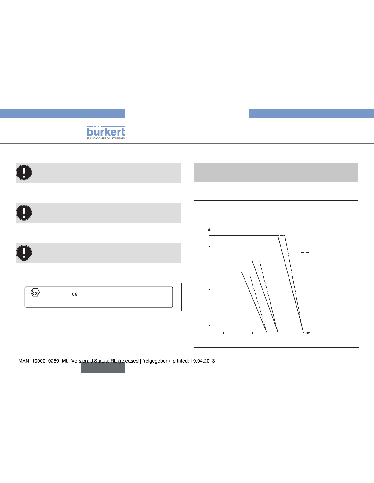
3.1.6. Temperature ranges in the Ex area
max. T
Environment
Medium (Seat seal PTFE)
≤ DN 25 > DN 25
T6 85 °C -10 - +45 °C -10 - +55 °C
T5 100 °C -10 - +60 °C -10 - +70 °C
T4 135 °C -10 - +95 °C -10 - +105 °C
Tab. 1: Temperature ranges Ex area
10 20 30 40 50 60 70 80 90 100 110 120 130
10
20
30
40
50
60
70
80
90
100
110
120
130
140
0
Medium temperature [°C]
Ambiente temperature [°C]
Temperature class T4
Temperature class T5
Temperature class T6
Valves ≤ DN 25
Valves > DN 25
Fig. 2: Temperature ranges Ex area
8
Basic safety instructions
english
Type 2730 / 2731 / 2731K
Page 9
4. GENERAL INFORMATION
4.1. Contact address
Germany
Bürkert Fluid Control Systems
Sales Center
Chr.-Bürkert-Str. 13-17
D-74653 Ingelfingen
Tel. : 07940 - 10 91 111
Fax: 07940 - 10 91 448
E-mail: info@de.burkert.com
International
Contact addresses are found on the final pages of the printed operating manual.
You can also find information on the Internet under:
www.burkert.com
4.2. Warranty
The warranty is only valid if the device is used as authorized in accordance with the specified application conditions.
4.3. Information on the internet
The operating instructions and data sheets for Type 2730 / 2731 /
2731K can be found on the Internet at: www.burkert.com
5. PRODUCT DESCRIPTION
5.1. General description
The piston-controlled diaphragm control valve Type 2730 / 2731 /
2731K is suitable for liquid media.
Using neutral gases or air (control media), it controls the flow of dirty,
aggressive, ultrapure or sterile media, even highly viscous media can
be used (flow media).
Follow instructions for use in the Ex area!
See chapter “3.1”.
The operation of the diaphragm control valve Type 2730 / 2731 /
2731K is possible only in combination with an control unit. Possible
control units are:
Positioner Type 8630, 8635, 8692, 8694, 8792
Process controller Type 8693, 8793
5.2. Properties
• Any flow direction.
• Self-draining for appropriate installation. The ends of the utilized
connections must be cylindrical.
• Free of empty space.
• Low-turbulence flow.
• High flow values by the streamlined valve body.
• Maintenance-free under normal conditions.
9
General information
english
Type 2730 / 2731 / 2731K
Page 10
5.2.1. Device versions
Actuator sizes
The piston-controlled diaphragm control valve is available for the
following actuator sizes:
ø 80 mm, ø 100 mm, ø 125 mm.
Pilot pressure
Designs with lower pilot pressure (reduced spring force) are
available on request.
Contact your Bürkert sales office or our Sales Center, e-mail:
info@de.buerkert.com
5.3. Structure and function
The operation of the diaphragm control valve Type 2730 / 2731
/ 2731K is possible only in combination with an control unit.
Possible control units are:
Positioner Type 8630, 8635, 8692, 8694, 8792
Process controller Type 8693, 8793
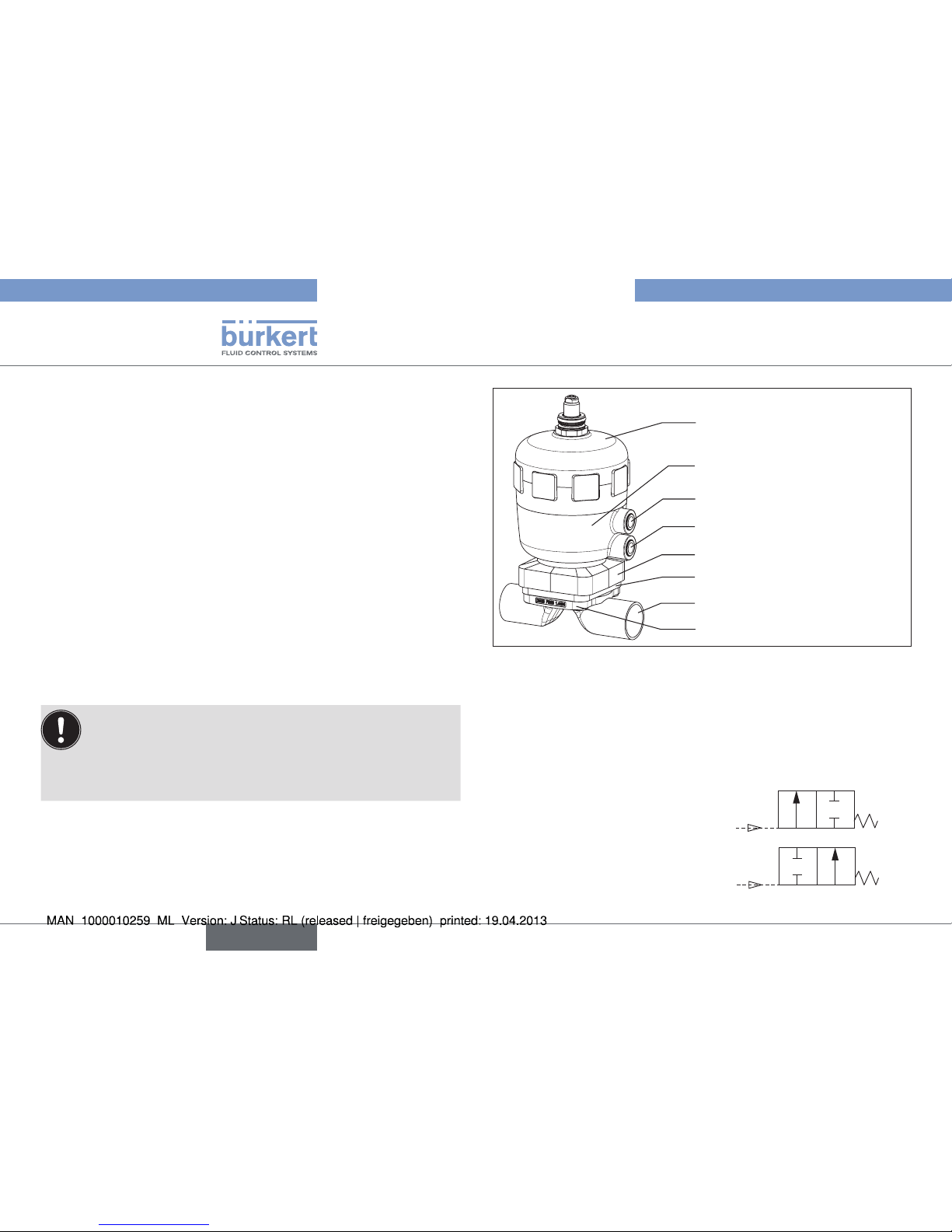
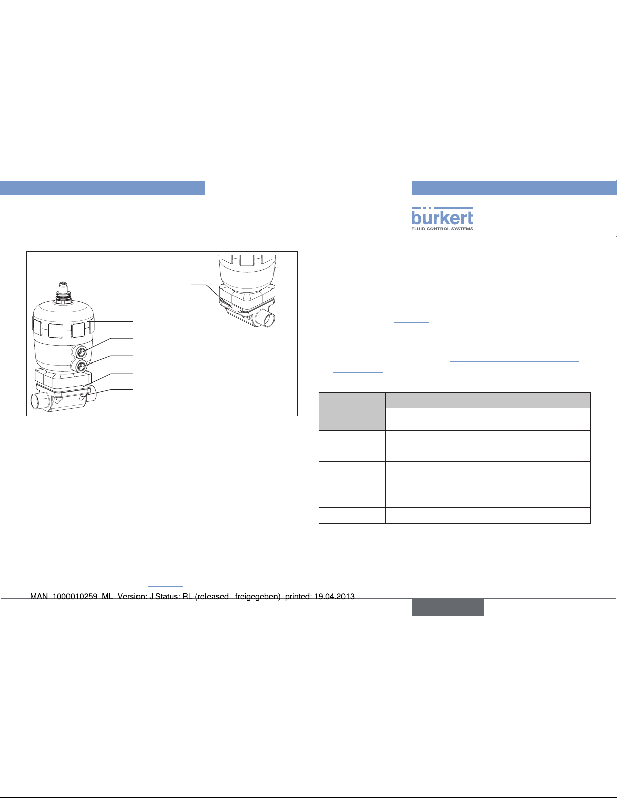
5.3.1. Structure
The piston-controlled diaphragm control valve consists of a pneumatically operated piston actuator and a 2/2-way valve body.
Actuator cover
Actuator body
Diaphragm socket
Line connection
Diaphragm body
Lower pilot air port
Upper pilot air port
Diaphragm
Fig. 3: Structure and description
5.3.2. Function / control functions (CF)
Spring force (CFA) or pneumatic pilot pressure (CFB) generates the
closing force on the diaphragm pressure piece. The force is transferred
via a spindle which is connected to the actuator piston.
Control function A (CFA)
Normally closed by spring action
Control function B (CFB)
Normally open by spring action
10
Product description
english
Type 2730 / 2731 / 2731K
Page 11
6. TECHNICAL DATA
WARNING!
Risk of injury from high pressure!
Important device-specific technical specifications are indicated on
the type label.
• Observe permitted pressure range on the type label of the device.
6.1. Conformity
In accordance with the EC Declaration of conformity, the diaphragm
control valve Type 2730 / 2731 / 2731K is compliant with the EC
Directives.
6.2. Standards
The applied standards, which verify conformity with the EC Directives,
can be found on the EC-Type Examination Certificate and / or the EC
Declaration of Conformity.
6.3. Approvals
The product is authorized for use in Zone 1 and 21 according to the
ATEX directive 94/9/EC of category 2 G/D.
Follow instructions for use in the Ex area!
See chapter “3.1”.
6.4. Type label
2731 A 25,0 EPDM VA
D29 Pmed 10 bar
Pilot 5,5-7 bar
00148320
Made in Germany
W14UN
Identification number
Control function
Sealing material
Type
Orifice (diaphragm size)
Date of manufacture
Line connection /
Permitted medium pressure
Body material
Permitted pilot pressure
Fig. 4: Type label (example)
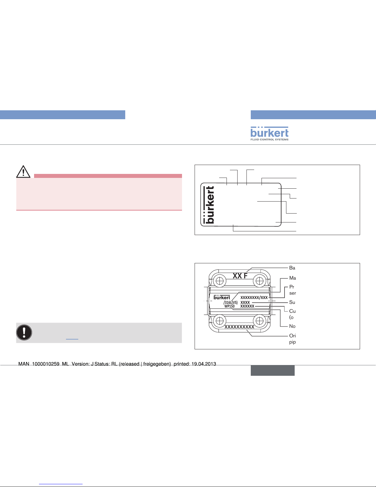
6.5. Labeling of the forged bodies
XXXXXXXXXX
XX F
1.4435/316L(VS)
PN16/CWP150
XXXXXXXX/XXX
XXXXXX
XXXX
Surface quality code
Customer-specific text
(optional)
Orifice connection and
pipe dimension
Batch number
Material
Production number /
serial number
Nominal pressure
Fig. 5: Labeling of the forged bodies
11
Technical data
english
Type 2730 / 2731 / 2731K
Page 12
6.6. Operating conditions
6.6.1. Temperature ranges
WARNING!
Risk of injury, chemical burns, scalding due to the device
rupturing at excessively high pressure!
• Do not exceed the maximum pilot and medium pressure.
• Observe permitted ambient and medium temperature.
• Observe specifications on the type label.
Follow instructions for use in the Ex area!
See chapter “3.1”.
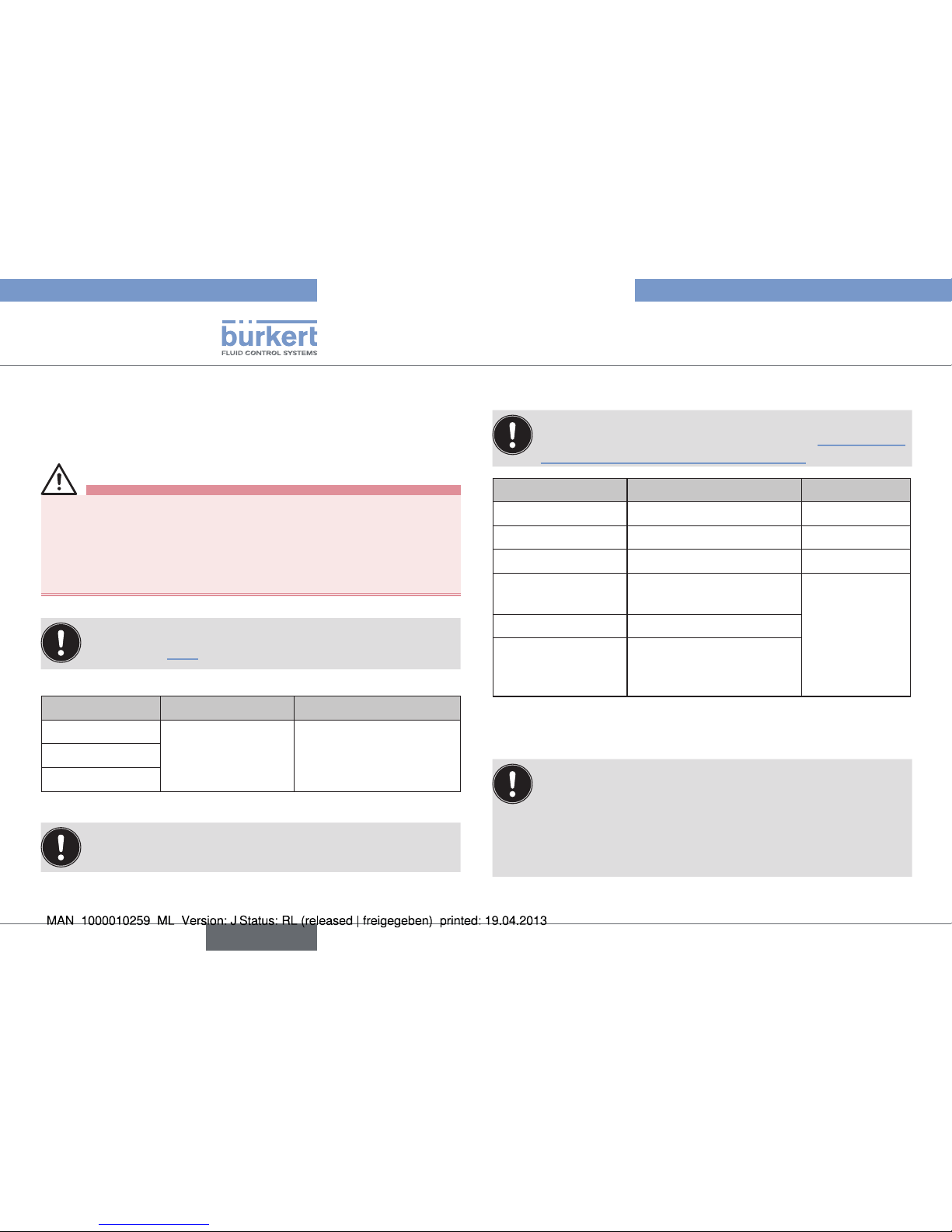
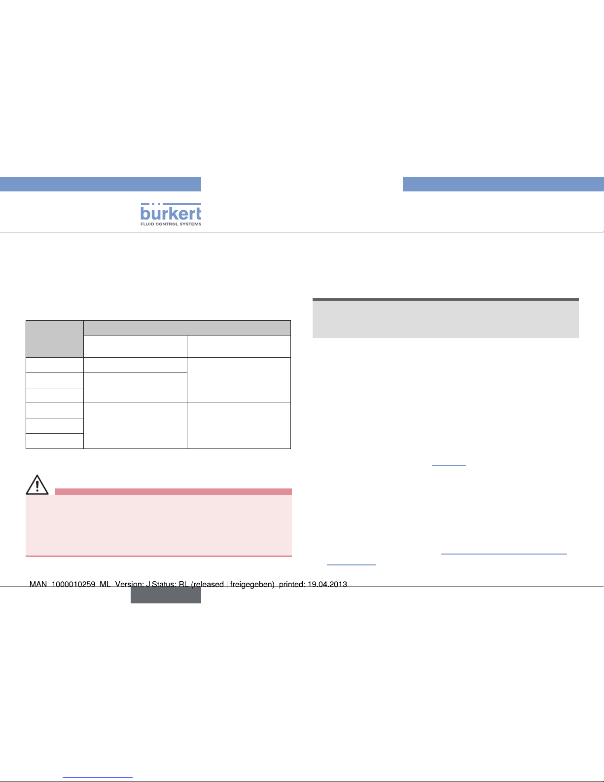
Permitted ambient temperature actuators
Actuator size Actuator material Environment
1)
ø 80 mm
PA, PPS -10 – +60 °Cø 100 mm
ø 125 mm
Tab. 2: Permitted ambient temperature actuators
1) If using a pilot valve / control unit, observe its
temperature range.
Permitted medium temperature for body
Plastic body: note that the permissible medium pressure is
dependent on the medium temperature (see “Fig. 6: Graph
of medium pressure / medium temperature”).
Body material Medium
PVDF (PD) -10 – +120 °C
PP (PP) -10 – +80 °C
PVC (PV) -10 – +60 °C
Stainless steel body
(VA)
1.4404 (AISI 316L)
-10 – +140 °C
Cast body (VG) 1.4435 (AISI 316L)
Forged body (VS)
1.4435 BN2 (AISI 316L)
according to ASME BPE
1997
Tab. 3: Permitted medium temperature for body
Permitted medium temperature for diaphragms
The indicated medium temperatures apply only to media
which do not corrode or swell the diaphragm materials.
The behavior of the medium with respect to the diaphragm
may be changed by the medium temperature.
The function properties, in particular the service life of the diaphragm, may deteriorate if the medium temperature increases.
12
Technical data
english
Type 2730 / 2731 / 2731K
Page 13
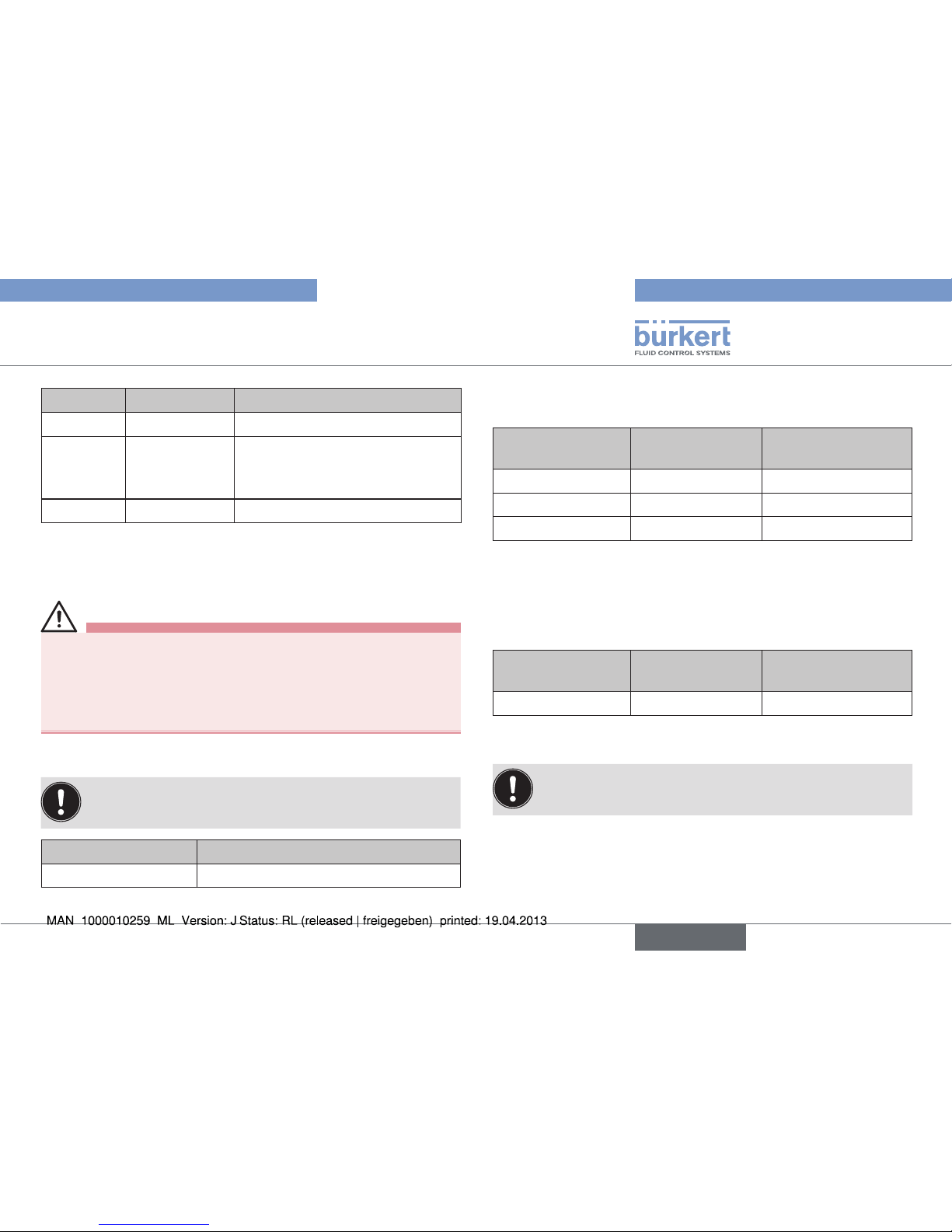
Diaphragm Medium Remarks
EPDM -10 – +130 °C Steam sterilization: up to +150 °C
FKM 0 – +130 °C
• dry up to + 150 °C
• otherwise only briefly up
to +150 °C
PTFE -10 – +130 °C Steam sterilization: up to +150 °C
Tab. 4: Permitted medium temperature for diaphragms
6.6.2. Pressure ranges
WARNING!
Risk of injury, chemical burns, scalding due to the device
rupturing at excessively high pressure!
• Do not exceed the maximum pilot and medium pressure.
• Observe permitted ambient and medium temperature.
• Observe specifications on the type label.
Pilot pressure for valves with pneumatic position controller
To ensure reliable operation with pneumatic position controller,
observe the permitted minimum and maximum pilot pressure!
Actuator size [mm] Pilot pressure
ø 80, ø 100, ø 125 5.5 – 7.0 bar
Tab. 5: Pilot pressure for valves with pneumatic position controller
Maximum pilot pressure for valves without pneumatic position
controller
Actuator size [mm] Actuator material
max. permitted pilot
pressure
2)
ø 80, ø 100 PA 10 bar
ø 125 PA 7 bar
ø 80, ø 100, ø 125 PPS 7 bar
Tab. 6: Maximum pilot pressure for valves without pneumatic
position controller
Maximum pilot pressure for valves without pneumatic position
controller - only control function B and stainless steel body (VA)
Actuator size [mm] Actuator material
max. permitted pilot
pressure
2)
ø 80, ø 100, ø 125 PA, PPS 6 bar
Tab. 7: Maximum pilot pressure for valves without pneumatic
position controller - only CFB and stainless steel body (VA)
2) Observe the maximum pressure range according to the
type label!
13
Technical data
english
Type 2730 / 2731 / 2731K
Page 14
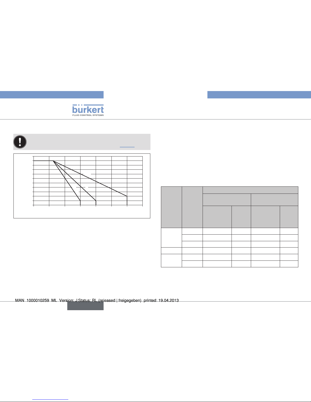
Medium pressure for plastic body
Plastic body: note that the permissible medium pressure is
dependent on the medium temperature (see “Fig. 6”).
Medium temperature [°C]
Medium pressure [bar]
0
2
4
6
8
10
20 40 60 80 100 120 140
PP
P
V
C
P
V
DF
Fig. 6: Graph of medium pressure / medium temperature
Pilot pressure for control function A
3)
The values apply to
• Plastic body PVDF (PD), PP (PP), PVC (PV)
• Forged steel body (VS)
• Precision casting body (VG)
• Stainless steel body (VA) with ISO weld end connection
ISO clamp connection
Threaded connection
Welded neck flange
Actuator size
[mm]
Orifice DN
(Diaphragm size)
[mm]
Max. sealed medium pressure [bar]
Pressure on one
side
Pressure on both
sides
EPDM/FKM PTFE EPDM/FKM PTFE
ø 80
15 10 10 10 10
20 10 10 10 10
25 10 7,5 8,5 5,5
ø 100 32 10 8 9 6
ø 125
40 10 10 10 9
50 8 7 7 6
Tab. 8: Pilot pressure for control function A
14
Technical data
english
Type 2730 / 2731 / 2731K
Page 15
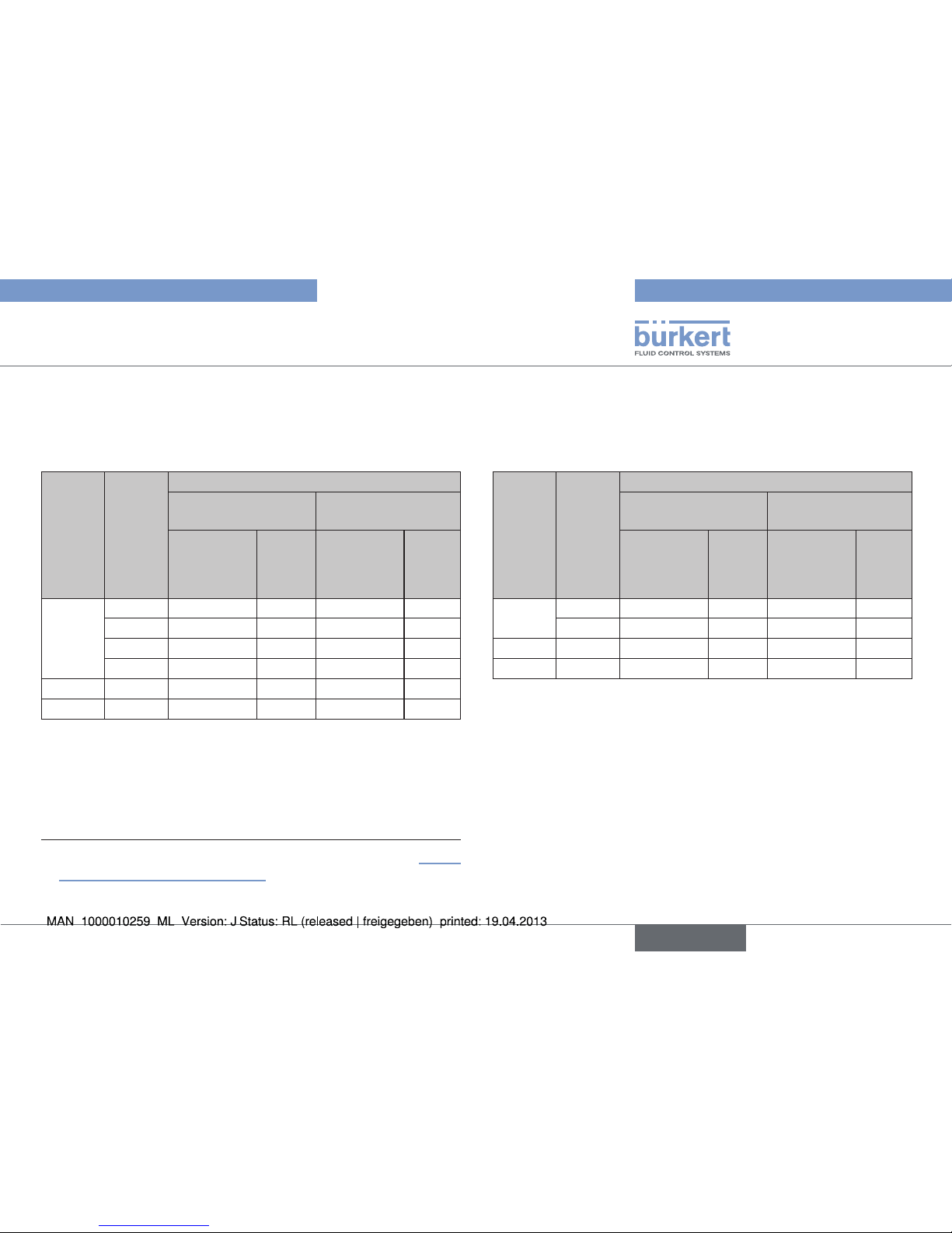
Operating pressure for control function A
3)
The values apply to
• Stainless steel body (VA) with DIN weld end connection
DIN clamp connection
Actuator size
[mm]
Orifice DN
(Diaphragm size)
[mm]
Max. sealed medium pressure [bar]
Pressure on one
side
Pressure on both
sides
EPDM/FKM PTFE EPDM/FKM PTFE
ø 80
15 10 10 10 10
20 10 10 10 10
25 10 10 10 9
32 10 8 7.5 6
ø 100 40 10 8 8 6
ø 125 50 10 10 10 8.5
Tab. 9: Operating pressure for control function A
3) The control functions are described in the chapter entitled “5.3.2.
Function / control functions (CF)”.
Operating pressure for control function A
3)
The values apply to
• Stainless steel body (VA) with OD weld end connection
BS clamp connection
Actuator size
[mm]
Orifice DN
(Diaphragm size)
[mm]
Max. sealed medium pressure [bar]
Pressure on one
side
Pressure on both
sides
EPDM/FKM PTFE EPDM/FKM PTFE
ø 80
20 10 10 10 10
25 10 10 10 9
ø 100 40 10 8 8 6
ø 125 50 10 10 10 8.5
Tab. 10: Operating pressure for control function A
15
Technical data
english
Type 2730 / 2731 / 2731K
Page 16
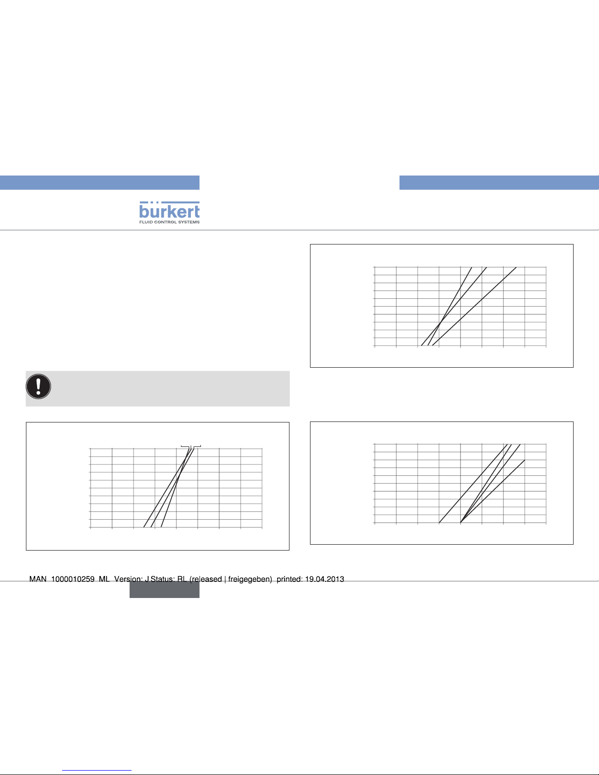
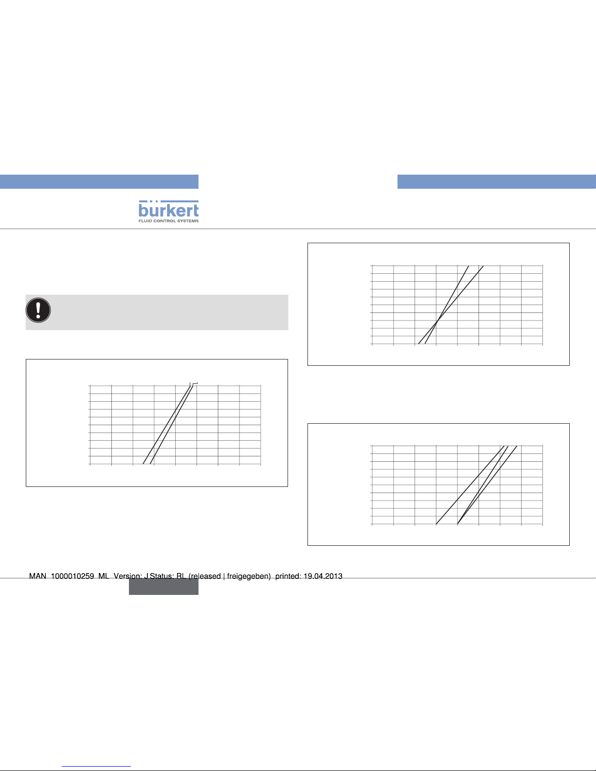
Required minimum pilot pressure depending on medium pressure
for control function B.
The values in the following graphs apply to:
• Plastic body PVDF (PD), PP (PP), PVC (PV)
• Forged steel body (VS)
• Precision casting body (VG)
• Stainless steel body (VA) with ISO- weld end connection
ISO clamp connection
Threaded connection
Welded neck flange
To protect the diaphragm during control function B, preferably
do not select the pilot pressure higher than is required to
switch the medium pressure.
Control function B / elastomer diaphragm
0
1
2
3
4
5
6
7
8
9
10
0 1 2 3 4 5 6 7 8
Pilot pressure [bar]
Medium pressure [bar]
ø 80 EPDM
DN15
DN20
DN25
Fig. 7: Pressure graph, actuator ø 80 mm, control function B,
elastomer diaphragm
0
1
2
3
4
5
6
7
8
9
10
0 1 2 3 4 5 6 7 8
Pilot pressure [bar]
Medium pressure [bar]
ø 100, ø 125 EPDM
DN32
DN40
DN50
Fig. 8: Pressure graph, actuator ø 100 mm and ø 125 mm,
control function B, elastomer diaphragm
Control function B / PTFE diaphragm
0
1
2
3
4
5
6
7
8
9
10
0 1 2 3 4 5 6 7 8
Pilot pressure [bar]
Medium pressure [bar]
ø 80, ø 100, ø 125 PTFE
DN32
DN40
DN15
DN20
DN25
DN50
Fig. 9: Pressure graph, actuator ø 80 mm, ø 100 mm and
ø 125 mm, control function B, PTFE diaphragm
16
Technical data
english
Type 2730 / 2731 / 2731K
Page 17
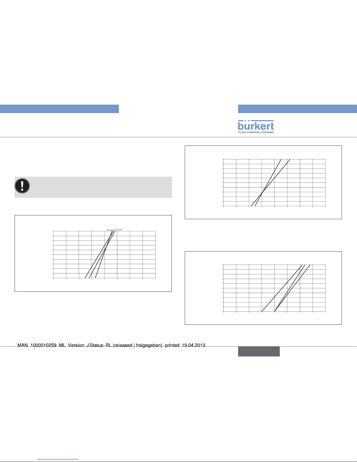
The values in the following graphs apply to:
• Stainless steel body (VA) with DIN weld end connection
DIN clamp connection
To protect the diaphragm during control function B, preferably
do not select the pilot pressure higher than is required to
switch the medium pressure.
Control function B / elastomer diaphragm
0
1
2
3
4
5
6
7
8
9
10
0 1 2 3 4 5 6 7 8
Pilot pressure [bar]
Medium pressure [bar]
ø 80 EPDM
DN15
DN20
DN25
DN32
Fig. 10: Pressure graph, actuator ø 80 mm, control function B,
elastomer diaphragm
0
1
2
3
4
5
6
7
8
9
10
0 1 2 3 4 5 6 7 8
Pilot pressure [bar]
Medium pressure [bar]
ø 100, ø 125 EPDM
DN40
DN50
Fig. 11: Pressure graph, actuator ø 100 mm and ø 125 mm,
control function B, elastomer diaphragm
Control function B / PTFE diaphragm
0
1
2
3
4
5
6
7
8
9
10
0 1 2 3 4 5 6 7 8
Pilot pressure [bar]
Medium pressure [bar]
ø 80, ø 100, ø 125 PTFE
DN40
DN50
DN15
DN20
DN25
DN32
Fig. 12: Pressure graph, actuator ø 80 mm, ø 100 mm and
ø 125 mm, control function B, PTFE diaphragm
17
Technical data
english
Type 2730 / 2731 / 2731K
Page 18
The values in the following graphs apply to:
• Stainless steel body (VA) with OD weld end connection
BS clamp connection
To protect the diaphragm during control function B, preferably
do not select the pilot pressure higher than is required to
switch the medium pressure.
Control function B / elastomer diaphragm
0
1
2
3
4
5
6
7
8
9
10
0 1 2 3 4 5 6 7 8
Pilot pressure [bar]
Medium pressure [bar]
ø 80 EPDM
DN20
DN25
Fig. 13: Pressure graph, actuator ø 80 mm, control function B,
elastomer diaphragm
0
1
2
3
4
5
6
7
8
9
10
0 1 2 3 4 5 6 7 8
Pilot pressure [bar]
Medium pressure [bar]
ø 100, ø 125 EPDM
DN40
DN50
Fig. 14: Pressure graph, actuator ø 100 mm and ø 125 mm,
control function B, elastomer diaphragm
Control function B / PTFE diaphragm
0
1
2
3
4
5
6
7
8
9
10
0 1 2 3 4 5 6 7 8
Pilot pressure [bar]
Medium pressure [bar]
ø 80, ø 100, ø 125 PTFE
DN40
DN50
DN20
DN25
Fig. 15: Pressure graph, actuator ø 80 mm, ø 100 mm und
ø 125 mm, control function B, PTFE diaphragm
18
Technical data
english
Type 2730 / 2731 / 2731K
Page 19
6.7. Flow values and characteristics
Flow values and characteristics for Types 2730 / 2731 /
2731K you find on Internet.
6.8. General technical data
Actuator sizes ø 80 mm
ø 100 mm
ø 125 mm
Connections
Pilot air port G1/4, stainless steel
Line connection
Type 2730 Socket and spigot
Type 2731 / 2731K Weld end: in accordance with EN ISO
1127 (ISO 4200), DIN 11850 R2
other connections on request
Materials
Body
Type 2730 PVDF (PD), PP (PP), PVC (PV)
Type 2731 Stainless steel precision casting (VG)
1.4435 (AISI 316L),
Stainless steel forged steel (VS)
1.4435 (AISI 316L)
Type 2731K Stainless steel body (VA) cold-formed
1.4404 (316L)
Actuator PA, PPS
Sealing elements actuator FKM, NBR
Diaphragm EPDM in food quality,
PTFE/EPDM,
FKM
19
Technical data
english
Type 2730 / 2731 / 2731K
Page 20
Media
Control medium Neutral gases, air
Quality classes in accordance with DIN ISO
8573-1
Dust content Class 5: max. particle size 40 μm, max. particle
density 10 mg/m³
Water content Class 3: max. pressure dew point - 20 °C or
min. 10 °C below the lowest operating
temperature
Oil content Class 5: max. 25 mg/m³ with TopControl
maxi 1 mg/m³ with SideControl
Flow media
Type 2730 Liquids; aggressive or abrasive media
Type 2731 / 2731K Liquids; ultrapure, sterile, aggressive
or abrasive media
Viscosity up to viscous
Installation position any position, preferably with the
actuator face up
Protection class IP67 in accordance with
IEC 529 / EN 60529
7. INSTALLATION
7.1. Safety instructions
DANGER!
Danger – high pressure in the equipment!
• Before loosening the lines and valves, turn off the pressure and
vent the lines.
WARNING!
Risk of injury from improper installation!
• Installation may be carried out by authorised technicians only
and with the appropriate tools!
Risk of injury from unintentional activation of the system and
an uncontrolled restart!
• Secure system from unintentional activation.
• Following assembly, ensure a controlled restart.
7.2. Before installation
• Before connecting the valve, ensure the pipelines are flush.
• The flow direction is optional.
7.2.1. Installation position
• The piston-controlled diaphragm control valve can be installed in
any installation position, preferably with the actuator face up.
20
Installation
english
Type 2730 / 2731 / 2731K
Page 21
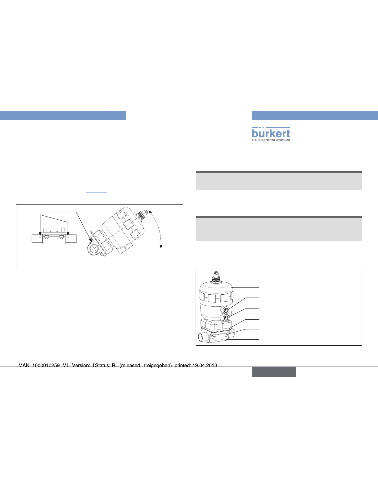
Installation for self-drainage of the body
4)
To ensure self-drainage:
→ Install body inclined by an angle α = 15° – 35° to the horizontal.
→ Forged and cast body: Mark on the body must point upwards
(12 o’clock position, see “Fig. 16”).
→ Observe an inclination angle of 1° – 5° to the line axis.
Angle α: 15 °– 35°
Inclination to the line axis 1° – 5°
Mark
α
Fig. 16: Installation position for self-drainage of the body
7.2.2. Preparatory work
→ Clean pipelines (sealing material, swarf, etc.).
→ Support and align pipelines.
4) Please request installation for 3A certification explicitly.
Devices with VG/VS/VA welded body:
NOTE!
Damage to the diaphragm or the actuator!
• Before welding in the body, remove the actuator.
Remove the actuator from the valve body:
NOTICE!
Damage to the diaphragm or the seat contour!
• When removing the actuator, ensure that the valve is in open
position.
→ Control function A pressurize the lower pilot air port with com-
pressed air (5 bar): valve opens.
→ Remove actuator with diaphragm by loosening the body screws.
Actuator
Valve body
Lower pilot air port
Upper pilot air port
Body screws (4x)
Diaphragm
Fig. 17: Installation
21
Installation
english
Type 2730 / 2731 / 2731K
Page 22
7.3. Installation
WARNING!
Risk of injury from improper installation!
Non-observance of the tightening torque is dangerous as the
device may be damaged.
• Observe the tightening torque (see “Tab. 11: Tightening torques
for diaphragms”).
7.3.1. Installation of the valve body
Welded bodies
→ Weld valve body in pipeline system.
Other body versions
→ Connect body to pipeline.
7.3.2. Installation of the actuator (welded
body)
Installation for actuator with control function A:
NOTICE!
Damage to the diaphragm or the seat contour!
• When installing the actuator, ensure that the valve is in open
position.
→ Control function A pressurize the lower pilot air port with com-
pressed air (5 bar): valve opens.
→ Lightly cross-tighten the body screws until the diaphragm is
between the body and actuator.
Do not tighten the screws yet.
→ Actuate the diaphragm control valve twice.
→ Without pressurization tighten the body screws to the permitted
tightening torque (see following table “Tab. 11: Tightening torques
for diaphragms”).
Installation for actuator with control functions B:
→ Lightly cross-tighten the body screws without pressurization until
the diaphragm is between the body and actuator.
Do not tighten the screws yet.
→ Pressurize upper pilot air port of the actuator with compressed
air (5 bar).
→ Actuate the diaphragm control valve twice.
→ With pressurization tighten the body screws to the permitted tight-
ening torque (see “Tab. 11: Tightening torques for diaphragms”).
Lower pilot air port
Upper pilot air port
Fig. 18: Pilot air port
22
Installation
english
Type 2730 / 2731 / 2731K
Page 23
Orifice DN
(diaphragm size)
Tightening torques for diaphragms [Nm]
EPDM PTFE
15 3.5 4
20 4 4.5
25
5 6
32
6 8
40
8 10
50 12 15
Tab. 11: Tightening torques for diaphragms
7.4. Pneumatic connection
DANGER!
Danger – high pressure in the equipment!
• Before loosening the lines and valves, turn off the pressure and
vent the lines.
WARNING!
Risk of injury from unsuitable connection hoses!
Hoses which cannot withstand the pressure and temperature
range may result in hazardous situations.
• Use only hoses which are authorised for the indicated pressure
and temperature range.
• Observe the data sheet specifications from the hose manufacturers.
The operation of the diaphragm control valve Type 2730 / 2731
/ 2731K is possible only in combination with an control unit.
Possible control units are:
Positioner Type 8630, 8635, 8692, 8694, 8792
Process controller Type 8693, 8793
Observe the type label!
The pneumatic connection of the control unit is described in
the respective operating instructions for the control unit.
23
Installation
english
Type 2730 / 2731 / 2731K
Page 24

7.4.1. Connection of the actuator
Control functions A:
→ Connect the control medium to the lower pilot air port of the
actuator (see “Fig. 19: Pneumatic connection”)
Control functions B:
→ Connect the control medium to the upper pilot air port of the
actuator (see “Fig. 19: Pneumatic connection”)
Silencer
For reducing the exhaust air noise: plug the silencer into the free air
discharge connection (see “Fig. 19: Pneumatic connection”)
If used in an aggressive environment, we recommend
conveying all free pneumatic connections into a neutral
atmosphere with the aid of a pneumatic hose.
Lower pilot air port
Upper pilot air port
Fig. 19: Pneumatic connection
Control air hose:
Control air hoses of sizes 6/4 mm or 1/4“ can be used.
7.5. Removal
DANGER!
Risk of injury from discharge of medium and pressure!
It is dangerous to remove a device which is under pressure due to
the sudden release of pressure or discharge of medium.
• Before removing a device, switch off the pressure and vent the
lines.
Procedure:
→ Loosen the pneumatic connection.
→ Remove the device.
NOTE!
Deformation of the diaphragm!
• For prolonged storage of the valves, slacken the housing screws.
24
Installation
english
Type 2730 / 2731 / 2731K
Page 25
8. ELECTRICAL CONTROL UNIT
The valve Type 2730 / 2731 / 2731K can be combined with following control units:
• Type 8630 Positioner TopControl Continuous
• Type 8635 Positioner SideControl
• Type 8692 Positioner TopControl
• Type 8694 Positioner TopControl Basic
• Type 8792 Positioner SideControl
• Type 8693 Process controller TopControl
• Type 8793 Process controller SideControl
Follow instructions for use in the Ex area!
See chapter “3.1”.
The electrical connection of the control unit is described in
the respective operating instructions for the control unit.
9. MALFUNCTIONS
Malfunction Cause /remedial action
Actuator does
not switch.
Pilot air port interchanged
5)
CFA: Connecting lower pilot air port
CFB: Connecting upper pilot air port
Pilot pressure too low
See pressure specifications on the type label.
Medium pressure too high
See pressure specifications on the type label.
Valve is not
sealed.
Medium pressure too high
See pressure specifications on the type label.
Pilot pressure too low
See pressure specifications on the type label.
Flow rate
reduced.
PTFE diaphragm bulging
→ Replace diaphragm.
Tab. 12: Malfunctions
5) see “Fig. 19: Pneumatic connection”
25
Electrical control unit
english
Type 2730 / 2731 / 2731K
Page 26
10. MAINTENANCE, CLEANING
10.1. Safety instructions
DANGER!
Danger – high pressure in the equipment!
• Before loosening the lines and valves, turn off the pressure and
vent the lines.
Risk of injury due to electrical shock!
• Before reaching into the system, switch off the power supply
and secure to prevent reactivation!
• Observe applicable accident prevention and safety regulations
for electrical equipment!
WARNING!
Risk of injury from improper maintenance!
• Installation may be carried out by authorized technicians only
and with the appropriate tools!
Risk of injury from unintentional activation of the system and
an uncontrolled restart!
• Secure system from unintentional activation.
• Following maintenance, ensure a controlled restart.
10.2. Maintenance work
10.2.1. Actuator
The actuator of the diaphragm control valve is maintenance-free
provided it is used according to these operating instructions.
10.2.2. Wearing parts of the diaphragm
control valve
Parts which are subject to natural wear:
• Seals
• Diaphragm
→ If leaks occur, replace the particular wearing part with an appro-
priate spare part (see chapter “12. Replacement parts”).
A bulging PTFE diaphragm may reduce the flow.
The replacing of the wearing parts is described in chapter
“11. Repairs”.
10.2.3. Inspection intervals
→ Check diaphragm for wear after maximum 10
5
switching cycles.
Muddy and abrasive media require correspondingly shorter
inspection intervals!
26
Maintenance, cleaning
english
Type 2730 / 2731 / 2731K
Page 27
10.2.4. Service life of the diaphragm
The service life of the diaphragm depends on the following factors:
• Diaphragm material
• Medium, Medium pressure, Medium temperature
• Actuator size
• Pilot pressure for CFB.
Protecting the diaphragm
→ For CFA match the actuator size (actuator force) to the medium
pressure to be actuated. If required, select the actuator with
reduced spring force EC04.
→ For CFB try and select the pilot pressure not higher than is
required to actuate the medium pressure.
10.2.5. Cleaning
Commercially available cleaning agents can be used to clean the
outside.
NOTE!
Avoid causing damage with cleaning agents.
• Before cleaning, check that the cleaning agents are compatible
with the body materials and seals.
Follow instructions for use in the Ex area!
See chapter “3.1”.
11. REPAIRS
11.1. Safety instructions
DANGER!
Danger – high pressure in the equipment!
• Before loosening the lines and valves, turn off the pressure and
vent the lines.
Risk of injury due to electrical shock!
• Before reaching into the system, switch off the power supply
and secure to prevent reactivation!
• Observe applicable accident prevention and safety regulations
for electrical equipment!
WARNING!
Risk of injury from improper maintenance!
• Installation may be carried out by authorised technicians only
and with the appropriate tools!
• Observe the tightening torques.
• On completion of the work check valve for leaks and function.
Risk of injury from unintentional activation of the system and
an uncontrolled restart!
• Secure system from unintentional activation.
• Following maintenance, ensure a controlled restart.
27
Repairs
english
Type 2730 / 2731 / 2731K
Page 28
11.2. Replacing the diaphragm
Required spare part
• Diaphragm
Fastening types
Orifice DN
(diaphragm
size)
Fastening types for diaphragms
PTFE EPDM / FKM
15 Diaphragm buttoned
Diaphragm buttoned20
Diaphragm with bayonet
catch
25
32
Diaphragm with bayonet
catch
Diaphragm screwed in40
50
Tab. 13: Fastening types for diaphragms
DANGER!
Risk of injury from discharge of medium and pressure!
It is dangerous to remove a device which is under pressure due to
the sudden release of pressure or discharge of medium.
• Before removing a device, switch off the pressure and vent the
lines.
Replacement for control function A
→ Clamp the valve body in a holding device
(applies only to valves not yet installed).
NOTICE!
Damage to the diaphragm or the seat contour!
• When removing the actuator, ensure that the valve is in open
position.
→ Pressurize lower pilot air port of the actuator with compressed
air (5 bar): valve opens.
→ Loosen the four body screws.
→ Remove the actuator from the body.
→ Unbutton or unscrew old diaphragm. If attachment is with a
bayonet catch, remove the diaphragm by rotating it through 90°.
→ Install new diaphragm.
→ Align diaphragm.
The marker flap of the diaphragm must be perpendicular to
the direction of flow (see “Fig. 20”)!
→ Place actuator back on the body.
→ Insert the body screws and lightly cross-tighten until the dia-
phragm is between the body and actuator.
Do not tighten the screws yet.
→ Actuate the diaphragm control valve twice.
→ Without pressurization tighten the body screws to the per-
mitted tightening torque (see “Tab. 14: Tightening torques for
diaphragms”).
28
Repairs
english
Type 2730 / 2731 / 2731K
Page 29
Actuator
Valve body
Lower pilot air port
Upper pilot air port
Body screws (4x)
Diaphragm
Marker flap of the
diaphragm
Fig. 20: Repairs
Replacement for control functions B
→ Clamp the valve body in a holding device.
(applies only to valves not yet installed).
→ Loosen the four body screws.
→ Remove the actuator from the body.
→ Unbutton or unscrew old diaphragm. If attachment is with a
bayonet catch, remove the diaphragm by rotating it through 90°.
→ Install new diaphragm.
→ Align diaphragm.
The marker flap of the diaphragm must be perpendicular to
the direction of flow (see “Fig. 20”)!
→ Place actuator back on the body.
→ Lightly cross-tighten the body screws without pressurization until
the diaphragm is between the body and actuator.
Do not tighten screws yet.
→ Pressurize upper pilot air port of the actuator with compressed
air (5 bar) (see “Fig. 20”).
→ Actuate the diaphragm control valve twice.
→ With pressurization tighten the body screws to the per-
mitted tightening torque (see “Tab. 14: Tightening torques for
diaphragms”).
Orifice DN
(diaphragm
size)
Tightening torques for diaphragms [Nm]
EPDM PTFE
15 3.5 4
20 4 4.5
25 5 6
32 6 8
40 8 10
50 12 15
Tab. 14: Tightening torques for diaphragms
29
Repairs
english
Type 2730 / 2731 / 2731K
Page 30

12. REPLACEMENT PARTS
WARNING!
Risk of injury when opening the actuator!
The actuator contains a tensioned spring. If the actuator is
opened, there is a risk of injury from the spring jumping out!
• The actuator must not be opened.
CAUTION!
Risk of injury and/or damage by the use of incorrect parts!
Incorrect accessories and unsuitable replacement parts may
cause injuries and damage the device and the surrounding area.
• Use only original accessories and original replacement parts
from Bürkert.
The diaphragm is available as a replacement part for the piston-controlled diaphragm control valve Type 2730 / 2731 / 2731K.
If you have any queries, please contact your Bürkert sales
office.
Diaphragm
Fig. 21: Diaphragm replacement part
12.1. Order table
Orifice DN
(diaphragm
size) [mm]
Order numbers for diaphragms
EPDM FKM PTFE
15 677 664 677 685 677 675
20 677 665 677 686 677 676
25 677 667 677 687 677 677
32 677 668 677 688 677 678
40 677 669 677 689 677 679
50 677 670 677 690 677 680
Tab. 15: Order numbers for diaphragms
30
Replacement parts
english
Type 2730 / 2731 / 2731K
Page 31

13. PACKAGING, TRANSPORT,
STORAGE
NOTE!
Transport damages!
Inadequately protected equipment may be damaged during transport.
• During transportation protect the device against wet and dirt in
shock-resistant packaging.
• Avoid exceeding or dropping below the permitted storage
temperature.
Incorrect storage may damage the device.
• Store the device in a dry and dust-free location!
• Storage temperature -20 – +65 °C.
Damage to the environment caused by device components
contaminated with media.
• Dispose of the device and packaging in an environmentally
friendly manner.
• Observe applicable regulations on disposal and the environment.
Note:
Observe national waste disposal regulations.
31
Packaging, transport, storage
english
Type 2730 / 2731 / 2731K
Page 32

32
english
Type 2730 / 2731 / 2731K
Page 33

33
1. DIE BEDIENUNGSANLEITUNG ............................................................35
1.1. Darstellungsmittel ...........................................................................35
1.2. Begriffsdefinition Gerät .................................................................35
2. BESTIMMUNGSGEMÄSSE VERWENDUNG ...................................36
2.1. Beschränkungen ............................................................................36
3. GRUNDLEGENDE SICHERHEITSHINWEISE ................................. 36
3.1. Hinweise für den Einsatz im explosionsgeschützten
(Ex-) Bereich ...................................................................................37
4. ALLGEMEINE HINWEISE .......................................................................... 39
4.1. Kontaktadresse ...............................................................................39
4.2. Gewährleistung...............................................................................39
4.3. Informationen im Internet ..............................................................39
5. PRODUKTBESCHREIBUNG ................................................................... 39
5.1. Allgemeine Beschreibung ............................................................39
5.2. Eigenschaften .................................................................................39
5.3. Aufbau und Funktion .....................................................................40
6. TECHNISCHE DATEN ................................................................................ 41
6.1. Konformität .......................................................................................41
6.2. Normen .............................................................................................41
6.3. Zulassungen ....................................................................................41
6.4. Typschild ..........................................................................................41
6.5. Beschriftung Schmiedegehäuse ................................................41
6.6. Betriebsbedingungen ....................................................................42
6.7. Durchflusswerte und Kennlinien .................................................49
6.8. Allgemeine Technische Daten .....................................................49
7. MONTAGE ........................................................................................................50
7.1. Sicherheitshinweise .......................................................................50
7.2. Vor dem Einbau ..............................................................................50
7.3. Einbau ...............................................................................................52
7.4. Pneumatischer Anschluss ............................................................53
8. DEMONTAGE ..................................................................................................54
9. ELEKTRISCHE ANSTEUERUNG ...........................................................55
10. STÖRUNGEN ................................................................................................55
11. WARTUNG, REINIGUNG .........................................................................56
11.1. Sicherheitshinweise.....................................................................56
11.2. Wartungsarbeiten ........................................................................56
12. INSTANDHALTUNG ...................................................................................57
12.1. Sicherheitshinweise.....................................................................57
12.2. Austausch der Membran ............................................................58
13. ERSATZTEILE ...............................................................................................60
13.1. Ersatzteilsätze ...............................................................................60
14. TRANSPORT, LAGERUNG, VERPACKUNG ..................................61
Kolbengesteuertes Membranregelventil Typ 2730/2731/2731K
Typ 2730 / 2731 / 2731K
deutsch
Page 34

34
Typ 2730 / 2731 / 2731K
deutsch
Page 35

35
Die Bedienungsanleitung
1. DIE BEDIENUNGSANLEITUNG
Die Bedienungsanleitung beschreibt den gesamten Lebenszyklus
des Geräts. Bewahren Sie diese Anleitung so auf, dass sie für jeden
Benutzer gut zugänglich ist und jedem neuen Eigentümer des Geräts
wieder zur Verfügung steht.
Die Bedienungsanleitung enthält wichtige Informationen zur
Sicherheit!
Das Nichtbeachten dieser Hinweise kann zu gefährlichen Situationen führen.
• Die Bedienungsanleitung muss gelesen und verstanden werden.
1.1. Darstellungsmittel
GEFAHR!
Warnt vor einer unmittelbaren Gefahr!
• Bei Nichtbeachtung sind Tod oder schwere Verletzungen die
Folge.
WARNUNG!
Warnt vor einer möglicherweise gefährlichen Situation!
• Bei Nichtbeachtung drohen schwere Verletzungen oder Tod.
VORSICHT!
Warnt vor einer möglichen Gefährdung!
• Nichtbeachtung kann mittelschwere oder leichte Verletzungen
zur Folge haben.
HINWEIS!
Warnt vor Sachschäden!
• Bei Nichtbeachtung kann das Gerät oder die Anlage beschädigt
werden.
bezeichnet wichtige Zusatzinformationen, Tipps und
Empfehlungen.
verweist auf Informationen in dieser Bedienungsanleitung
oder in anderen Dokumentationen.
→ markiert einen Arbeitsschritt, den Sie ausführen müssen.
1.2. Begriffsdefinition Gerät
→ Der in dieser Anleitung verwendeten Begriff „Gerät“ steht immer
für das kolbengesteuerte Membranregelventil Typ 2730 / 2731
/ 2731K.
Typ 2730 / 2731 / 2731K
deutsch
Page 36

36
Bestimmungsgemäße Verwendung
2. BESTIMMUNGSGEMÄSSE
VERWENDUNG
Bei nicht bestimmungsgemäßem Einsatz des Membranregelventils Typ 2730 / 2731 / 2731K können Gefahren für Personen, Anlagen in der Umgebung und die Umwelt entstehen.
• Das Gerät ist für die Steuerung des Durchflusses von flüssigen
Medien konzipiert.
• Für den Einsatz sind die in den Vertragsdokumenten, der Bedienungsanleitung und auf dem Typschild spezifizierten zulässigen
Daten, Betriebs- und Einsatzbedingungen zu beachten. Die
vorgesehenen Einsatzfälle sind im Kapitel „5. Produktbeschreibung“ aufgeführt.
• Das Gerät nur in Verbindung mit von Bürkert empfohlenen bzw.
zugelassenen Fremdgeräten und -komponenten einsetzen.
• Voraussetzungen für den sicheren und einwandfreien Betrieb
sind sachgemäßer Transport, sachgemäße Lagerung und Installation sowie sorgfältige Bedienung und Instandhaltung.
• Setzen Sie das Gerät nur bestimmungsgemäß ein.
2.1. Beschränkungen
Beachten Sie bei der Ausfuhr des Systems/Geräts gegebenenfalls
bestehende Beschränkungen.
3. GRUNDLEGENDE
SICHERHEITSHINWEISE
Diese Sicherheitshinweise berücksichtigen keine
• Zufälligkeiten und Ereignisse, die bei Montage, Betrieb und Wartung
der Geräte auftreten können.
• ortsbezogenen Sicherheitsbestimmungen, für deren Einhaltung, auch
in Bezug auf das Montagepersonal, der Betreiber verantwortlich ist.
GEFAHR!
Gefahr durch hohen Druck!
• Vor dem Lösen von Leitungen und Ventilen den Druck abschalten und Leitungen entlüften.
Gefahr durch elektrische Spannung!
• Vor Eingriffen in das Gerät die Spannung abschalten und vor
Wiedereinschalten sichern!
• Die geltenden Unfallverhütungs- und Sicherheitsbestimmungen
für elektrische Geräte beachten!
WARNUNG!
Verletzungsgefahr bei Öffnung des Antriebs!
Der Antrieb enthält eine gespannte Feder. Bei Öffnung des Antriebs
kann es durch die herausspringende Feder zu Verletzungen kommen!
• Der Antrieb darf nicht geöffnet werden.
Typ 2730 / 2731 / 2731K
deutsch
Page 37

37
Grundlegende Sicherheitshinweise
VORSICHT!
Verbrennungsgefahr!
Bei Dauerbetrieb kann die Geräteoberfläche heiß werden.
• Das Gerät nicht mit bloßen Händen berühren.
Allgemeine Gefahrensituationen.
Zum Schutz vor Verletzungen ist zu beachten:
• Dass die Anlage nicht unbeabsichtigt betätigt werden kann.
• Installations- und Instandhaltungsarbeiten dürfen nur von autorisiertem Fachpersonal mit geeignetem Werkzeug ausgeführt
werden.
• Nach einer Unterbrechung der elektrischen oder pneumatischen
Versorgung ist ein definierter oder kontrollierter Wiederanlauf
des Prozesses zu gewährleisten.
• Das Gerät darf nur in einwandfreiem Zustand und unter Beachtung der Bedienungsanleitung betrieben werden.
• Für die Einsatzplanung und den Betrieb des Geräts müssen die
allgemeinen Regeln der Technik eingehalten werden.
Zum Schutz vor Sachschäden am Gerät ist zu beachten:
• In die Medienanschlüsse nur Medien einspeisen, die im Kapitel
„6. Technische Daten“ aufgeführt sind.
• Ventil nicht mechanisch belasten (z. B. durch Ablage von Gegenständen oder als Trittstufe).
• Keine äußerlichen Veränderungen an den Ventilen vornehmen.
Gehäuseteile und Schrauben nicht lackieren.
Das Membranregelventil Typ 2730 / 2731 / 2731K wurde
unter Einbeziehung der anerkannten sicherheitstechnischen
Regeln entwickelt und entspricht dem Stand der Technik.
Trotzdem können Gefahren entstehen.
Bei Nichtbeachtung dieser Bedienungsanleitung und ihrer Hinweise
sowie bei unzulässigen Eingriffen in das Gerät entfällt jegliche Haftung unsererseits, ebenso erlischt die Gewährleistung auf Geräte
und Zubehörteile!
3.1. Hinweise für den Einsatz
im explosionsgeschützten
(Ex-) Bereich
3.1.1. Sicherheitshinweise
Bei Einsatz im Ex-Bereich Zone (Gas) 1 und 2,
Zone (Staub) 21 und 22, gilt:
GEFAHR!
Explosionsgefahr durch elektrostatische Aufladung!
Bei plötzlicher Entladung elektrostatisch aufgeladener Geräte oder
Personen besteht im Ex-Bereich Explosionsgefahr.
• Durch geeignete Maßnahmen sicherstellen, dass es im ExBereich zu keinen elektrostatischen Aufladungen kommen kann.
• Die Geräteoberfläche nur durch leichtes Abwischen mit einem
feuchten oder antistatischen Tuch reinigen.
Typ 2730 / 2731 / 2731K
deutsch
Page 38

38
Grundlegende Sicherheitshinweise
3.1.2. Medien im Ex-Bereich
Werden explosionsfähige Medien verwendet, kann dadurch
eine zusätzliche Explosionsgefahr auftreten!
3.1.3. Ansteuerung im Ex-Bereich
Die Ansteuerung kann den Einsatz in explosionsfähiger Atmosphäre einschränken. Bedienungsanleitung der Ansteuerung
beachten.
3.1.4. Reinigung im Ex-Bereich
Reinigungsmittel auf Zulassung in explosionsfähiger Atmosphäre prüfen.
3.1.5. Klebeschild für Ex-Bereich
ACHTUNG: In Ex-Bereichen darf die Oberfläche
nur mit einem feuchten Tuch gereinigt werden
CAUTI
ON: In Hazardous Areas the surface
may
only be cleaned with a wet towel
II 2G c T4 IP65/67
II 2D c T135°C
Warnung: Im Ex-Bereich Oberfläche
nur mit feuchtem Tuch reinigen
Warning: In Hazardous Areas the surface
may only be cleaned with a damp cloth
Nicht gültig für angebaute Geräte
Not valid for added devices
Bild 1: Klebeschild Ex-Bereich
3.1.6. Temperaturbereiche im Ex-Bereich
max. T
Umgebung
Medium (bei PTFE-Dichtung)
bis DN 25 über DN 25
T6 85 °C -10 ... +45 °C -10 ... +55 °C
T5 100 °C -10 ... +60 °C -10 ... +70 °C
T4 135 °C -10 ... +95 °C -10 ... +105 °C
Tab. 1: Temperaturbereiche Ex-Bereich
10 20 30 40 50 60 70 80 90 100 110 120 130
10
20
30
40
50
60
70
80
90
100
110
120
130
140
0
Mediumstemperatur [°C]
Umgebungstemperatur [°C]
Temperaturklasse T4
Temperaturklasse T5
Temperaturklasse T6
Ventile bis DN 25
Ventile größer DN 25
Bild 2: Temperaturbereiche Ex-Bereich
Typ 2730 / 2731 / 2731K
deutsch
Page 39

39
Allgemeine Hinweise
4. ALLGEMEINE HINWEISE
4.1. Kontaktadresse
Deutschland
Bürkert Fluid Control System
Sales Center
Chr.-Bürkert-Str. 13-17
D-74653 Ingelfingen
Tel. + 49 (0) 7940 - 10 111
Fax + 49 (0) 7940 - 10 448
E-mail: info@de.buerkert.com
International
Die Kontaktadressen finden Sie auf den letzten Seiten der
gedruckten Bedienungsanleitung.
Außerdem im Internet unter: www.burkert.com
4.2. Gewährleistung
Voraussetzung für die Gewährleistung ist der bestimmungsgemäße
Verwendung des Geräts unter Beachtung der spezifizierten
Einsatzbedingungen.
4.3. Informationen im Internet
Bedienungsanleitungen und Datenblätter zum Typ 2730 / 2731 /
2731K finden Sie im Internet unter: www.buerkert.de
5. PRODUKTBESCHREIBUNG
5.1. Allgemeine Beschreibung
Das kolbengesteuerte Membranregelventil Typ 2730 / 2731 / 2731K
ist geeignet für flüssige Medien.
Es steuert mittels neutraler Gase oder Luft (Steuermedien) den Durchfluss von verschmutzten, aggressiven, hochreinen oder sterilen Medien,
auch Medien mit hoher Viskosität sind einsetzbar (Durchflussmedien).
Hinweise für den Einsatz im Ex-Bereich beachten!
Siehe Kapitel „3.1“ .
Das Membranregelventil Typ 2730 / 2731 / 2731K kann nur in Kombination mit einer Ansteuerung betrieben werden. Mögliche Ansteuerungen sind:
Positioner Typ 8630, 8635, 8692, 8694, 8792
Prozessregler Typ 8693, 8793
5.2. Eigenschaften
• Beliebige Durchflussrichtung.
• Selbstentleerend bei entsprechendem Einbau. Die Enden der
verwendeten Anschlüsse müssen zylindrisch zulaufen.
• Totraumfrei.
• Turbulenzarme Strömung.
• Hohe Durchflusswerte durch strömungsgünstiges Ventilgehäuse.
• Unter normalen Bedingungen wartungsfrei.
Typ 2730 / 2731 / 2731K
deutsch
Page 40

40
Produktbeschreibung
5.2.1. Gerätevarianten
Antriebsgrößen
Das kolbengesteuerte Membranregelventil ist für folgende Antriebsgrößen lieferbar:
ø 80 mm, ø 100 mm, ø 125 mm.
Steuerdruck
Ausführungen mit geringerem Steuerdruck (reduzierte Federkraft)
sind auf Anfrage erhältlich.
Wenden Sie sich an Ihre Bürkert Vertriebsniederlassung oder an
unser Sales Center, E-mail: info@de.buerkert.com
5.3. Aufbau und Funktion
Das Membranregelventil Typ 2730 / 2731 / 2731K kann
nur in Kombination mit einer Ansteuerung betrieben werden.
Mögliche Ansteuerungen sind:
Positioner Typ 8630, 8635, 8692, 8694, 8792
Prozessregler Typ 8693, 8793
5.3.1. Aufbau
Das kolbengesteuerte Membranregelventil besteht aus einem pneumatisch betätigten Kolbenantrieb und einem 2/2-Wege-Ventilgehäuse.
Antriebsdeckel
Antriebsgehäuse
Membransockel
Leitungsanschluss
Membrangehäuse
Steuerluftanschluss unten
Steuerluftanschluss oben
Membran
Bild 3: Aufbau und Beschreibung
5.3.2. Funktion / Steuerfunktionen (SF)
Federkraft (SFA) oder pneumatischer Steuerdruck (SFB) erzeugen
die Schließkraft des Membrandruckstücks. Über eine Spindel, die
mit dem Antriebskolben verbunden ist, wird die Kraft übertragen.
Steuerfunktion A (SFA)
In Ruhestellung durch Federkraft
geschlossen
Steuerfunktion B (SFB)
In Ruhestellung durch Federkraft
geöffnet
Typ 2730 / 2731 / 2731K
deutsch
Page 41

41
Technische Daten
6. TECHNISCHE DATEN
WARNUNG!
Verletzungsgefahr durch hohen Druck
Wichtige gerätespezifische technische Angaben sind auf dem
Typschild angegeben.
• Zulässiger Druckbereich auf dem Typschild des Geräts beachten.
6.1. Konformität
Das Membranregelventil Typ 2730 / 2731 / 2731K ist konform zu den
EG-Richtlinien entsprechend der EG-Konformitätserklärung.
6.2. Normen
Die angewandten Normen, mit denen die Konformität mit den EG-Richtlinien nachgewiesen wird, sind in der EG-Baumusterprüfbescheinigung
und/oder der EG-Konformitätserklärung nachzulesen.
6.3. Zulassungen
Das Produkt ist entsprechend der ATEX Richtlinie 94/9/EG der
Kategorie 2 G/D zum Einsatz in Zone 1 und 21 zugelassen.
Hinweise für den Einsatz im Ex-Bereich beachten!
Siehe Kapitel „3.1“ .
6.4. Typschild
2731 A 25,0 EPDM VA
D29 Pmed 10 bar
Pilot 5,5-7 bar
00148320
Made in Germany
W14UN
Identnummer
Steuerfunktion
Dichtwerkstoff
Typ
Nennweite (Membrangröße)
Herstellerdatum
Leitungsanschluss /
Zulässiger Mediumsdruck
Gehäusewerkstoff
Zulässiger Steuerdruck
Bild 4: Beschreibung Typschild (Beispiel)
6.5. Beschriftung Schmiedegehäuse
XXXXXXXXXX
XX F
1.4435/316L(VS)
PN16/CWP150
XXXXXXXX/XXX
XXXXXX
XXXX
Code Oberflächengüte
kundenspezifischer Text
(optional)
Nennweite Anschluss
und Rohrmaß
Chargennummer
Werkstoff
Fertigungsnummer /
Seriennummer
Nenndruck
Bild 5: Beschriftung Schmiedegehäuse
Typ 2730 / 2731 / 2731K
deutsch
Page 42

42
Technische Daten
6.6. Betriebsbedingungen
6.6.1. Temperaturbereiche
WARNUNG!
Gefahr von Verletzung, Verätzung, Verbrühung durch Bersten
des Geräts bei zu hohem Druck!
• Maximalen Steuerdruck und Mediumsdruck nicht überschreiten.
• Zulässige Umgebungs- und Mediumstemperatur einhalten.
• Angaben auf dem Typschild beachten.
Hinweise für den Einsatz im Ex-Bereich beachten!
Siehe Kapitel „3.1“ .
Zulässige Umgebungstemperatur für Antriebe
Antriebsgröße Antriebswerkstoff Umgebung
1)
ø 80 mm
PA, PPS -10 ... +60 °Cø 100 mm
ø 125 mm
Tab. 2: Zulässige Umgebungstemperatur für Antriebe
1) Bei Verwendung eines Vorsteuerventils / Ansteuerung
dessen Temperaturbereich beachten.
Zulässige Mediumstemperatur für Gehäuse
Bei Kunststoffgehäusen: zulässigen Mediumsdruck in Abhängigkeit der Mediumstemperatur beachten (siehe „Bild 6:
Diagramm Mediumsdruck / Mediumstemperatur“).
Gehäusewerkstoff Medium
PVDF (PD) -10 ... +120 °C
PP (PP) -10 ... +80 °C
PVC (PV) -10 ... +60 °C
Rohrgehäuse (VA) 1.4404 (AISI 316L)
-10 ... +140 °C
Gussgehäuse (VG) 1.4435 (AISI 316L)
Schmiedegehäuse
(VS)
1.4435 BN2 (AISI 316L)
nach ASME BPE 1997
Tab. 3: Zulässige Mediumstemperatur für Gehäuse
Zulässige Mediumstemperatur für Membranen
Die angegebenen Mediumstemperaturen gelten nur für
Medien welche die Membranwerkstoffe nicht angreifen oder
aufquellen lassen.
Das Verhalten des Mediums gegenüber der Membran kann sich durch
die Mediumstemperatur verändern.
Die Funktionseigenschaften insbesondere die Lebensdauer der Membran
können sich bei steigender Mediumstemperatur verschlechtern.
Typ 2730 / 2731 / 2731K
deutsch
Page 43

43
Technische Daten
Membran Medium Bemerkungen
EPDM -10 ... +130 °C Dampfsterilisierung: bis +150 °C
FKM 0 ... +130 °C
• trocken bis + 150 °C
• sonst nur kurz bis +150 °C
PTFE -10 ... +130 °C Dampfsterilisierung: bis +150 °C
Tab. 4: Zulässige Mediumstemperatur für Membranen
6.6.2. Druckbereiche
WARNUNG!
Gefahr von Verletzung, Verätzung, Verbrühung durch Bersten
des Geräts bei zu hohem Druck!
• Maximalen Steuerdruck und Mediumsdruck nicht überschreiten.
• Zulässige Umgebungs- und Mediumstemperatur einhalten.
• Angaben auf dem Typschild beachten.
Steuerdruck für Ventile mit pneumatischem Stellungsregler
Für den sicheren Betrieb mit pneumatischem Stellungsregler den zulässigen minimalen und maximalen Steuerdruck
beachten!
Antriebsgröße [mm] Steuerdruck
ø 80, ø 100, ø 125 5,5 ... 7,0 bar
Tab. 5: Steuerdruck für Ventile mit pneumatischem Stellungsregler
Maximaler Steuerdruck für Ventile ohne pneumatischem
Stellungsregler
Antriebsgröße
[mm]
Antriebswerkstoff
max. zulässiger
Steuerdruck
2)
ø 80, ø 100 PA 10 bar
ø 125 PA 7 bar
ø 80, ø 100, ø 125 PPS 7 bar
Tab. 6: Maximaler Steuerdruck für Ventile ohne pneumatischem
Stellungsregler
Maximaler Steuerdruck für Ventile ohne pneumatischem Stellungsregler - nur Steuerfunktion B und Rohrgehäuse (VA)
Antriebsgröße
[mm]
Antriebswerkstoff
max. zulässiger
Steuerdruck
2)
ø 80, ø 100, ø 125 PA, PPS 6 bar
Tab. 7: Maximaler Steuerdruck für Ventile ohne pneumatischem
Stellungsregler - nur SFB und Rohrgehäuse (VA)
2) Den maximalen Druckbereich laut Typschild beachten!
Typ 2730 / 2731 / 2731K
deutsch
Page 44

44
Technische Daten
Mediumsdruck für Kunststoffgehäuse
Bei Kunststoffgehäusen: zulässigen Mediumsdruck in Abhängigkeit von der Mediumstemperatur beachten (siehe „Bild 6“).
Mediumstemperatur [°C]
Mediumsdruck [bar]
0
2
4
6
8
10
20 40 60 80 100 120 140
PP
P
V
C
P
V
DF
Bild 6: Diagramm Mediumsdruck / Mediumstemperatur
Mediumsdruck bei Steuerfunktion A
3)
Die Werte sind gültig für
• Kunststoffgehäuse PVDF (PD), PP (PP), PVC (PV)
• Schmiedestahlgehäuse (VS)
• Feingussgehäuse (VG)
• Rohrgehäuse (VA) mit ISO-Schweißanschluss
ISO-Clampanschluss
Muffenanschluss
Vorschweißflansch
Antriebsgröße
[mm]
Nennweite DN
(Membrangröße)
[mm]
Max. dichtgehaltener Mediumsdruck [bar]
Druck einseitig
anstehend
Druck beidseitig
anstehend
EPDM/FKM PTFE EPDM/FKM PTFE
ø 80
15 10 10 10 10
20 10 10 10 10
25 10 7,5 8,5 5,5
ø 100 32 10 8 9 6
ø 125
40 10 10 10 9
50 8 7 7 6
Tab. 8: Mediumsdruck bei Steuerfunktion A
Typ 2730 / 2731 / 2731K
deutsch
Page 45

45
Technische Daten
Mediumsdruck bei Steuerfunktion A
3)
Die Werte sind gültig für
• Rohrgehäuse (VA) mit DIN-Schweißanschluss
DIN-Clampanschluss
Antriebsgröße
[mm]
Nennweite DN
(Membrangröße)
[mm]
Max. dichtgehaltener Mediumsdruck [bar]
Druck einseitig
anstehend
Druck beidseitig
anstehend
EPDM/FKM PTFE EPDM/FKM PTFE
ø 80
15 10 10 10 10
20 10 10 10 10
25 10 10 10 9
32 10 8 7,5 6
ø 100 40 10 8 8 6
ø 125 50 10 10 10 8,5
Tab. 9: Mediumsdruck bei Steuerfunktion A
3) Die Steuerfunktionen sind im Kapitel „5.3.2. Funktion /
Steuerfunktionen (SF)“ beschrieben.
Mediumsdruck bei Steuerfunktion A
3)
Die Werte sind gültig für
• Rohrgehäuse (VA) mit OD-Schweißanschluss
BS-Clampanschluss
Antriebsgröße
[mm]
Nennweite DN
(Membrangröße)
[mm]
Max. dichtgehaltener Mediumsdruck [bar]
Druck einseitig
anstehend
Druck beidseitig
anstehend
EPDM/FKM PTFE EPDM/FKM PTFE
ø 80
20 10 10 10 10
25 10 10 10 9
ø 100 40 10 8 8 6
ø 125 50 10 10 10 8,5
Tab. 10: Mediumsdruck bei Steuerfunktion A
Typ 2730 / 2731 / 2731K
deutsch
Page 46

46
Technische Daten
Erforderlicher Mindeststeuerdruck in Abhängigkeit vom Mediumsdruck für Steuerfunktion B
Die Werte in den nachfolgenden Diagrammen sind gültig für
• Kunststoffgehäuse PVDF (PD), PP (PP), PVC (PV)
• Schmiedestahlgehäuse (VS)
• Feingussgehäuse (VG)
• Rohrgehäuse (VA) mit ISO-Schweißanschluss
ISO-Clampanschluss
Muffenanschluss
Vorschweißflansch
Zur Schonung der Membran bei Steuerfunktion B den Steuerdruck möglichst nicht höher wählen, als zum Schalten des
Mediumsdrucks nötig.
Steuerfunktion B / Elastomer-Membran
0
1
2
3
4
5
6
7
8
9
10
0 1 2 3 4 5 6 7 8
Steuerdruck [bar]
Mediumsdruck [bar]
ø 80 EPDM
DN15
DN20
DN25
Bild 7: Druckdiagramm, Antrieb ø 80 mm, Steuerfunktion B,
Elastomer-Membran
0
1
2
3
4
5
6
7
8
9
10
0 1 2 3 4 5 6 7 8
Steuerdruck [bar]
Mediumsdruck [bar]
ø 100, ø 125 EPDM
DN32
DN40
DN50
Bild 8: Druckdiagramm, Antrieb ø 100 mm und ø 125 mm,
Steuerfunktion B, Elastomer-Membran
Steuerfunktion B / PTFE-Membran
0
1
2
3
4
5
6
7
8
9
10
0 1 2 3 4 5 6 7 8
Steuerdruck [bar]
Mediumsdruck [bar]
ø 80, ø 100, ø 125 PTFE
DN32
DN40
DN15
DN20
DN25
DN50
Bild 9: Druckdiagramm, Antrieb ø 80 mm, ø 100 mm und
ø 125 mm, Steuerfunktion B, PTFE-Membran
Typ 2730 / 2731 / 2731K
deutsch
Page 47

47
Technische Daten
Die Werte in den nachfolgenden Diagrammen sind gültig für
• Rohrgehäuse (VA) mit DIN-Schweißanschluss
DIN-Clampanschluss
Zur Schonung der Membran bei Steuerfunktion B den Steuerdruck möglichst nicht höher wählen, als zum Schalten des
Mediumsdrucks nötig.
Steuerfunktion B / Elastomer-Membran
0
1
2
3
4
5
6
7
8
9
10
0 1 2 3 4 5 6 7 8
Steuerdruck [bar]
Mediumsdruck [bar]
ø 80 EPDM
DN15
DN20
DN25
DN32
Bild 10: Druckdiagramm, Antrieb ø 80 mm, Steuerfunktion B,
Elastomer-Membran
0
1
2
3
4
5
6
7
8
9
10
0 1 2 3 4 5 6 7 8
Steuerdruck [bar]
Mediumsdruck [bar]
ø 100, ø 125 EPDM
DN40
DN50
Bild 11: Druckdiagramm, Antrieb ø 100 mm und ø 125 mm,
Steuerfunktion B, Elastomer-Membran
Steuerfunktion B / PTFE-Membran
0
1
2
3
4
5
6
7
8
9
10
0 1 2 3 4 5 6 7 8
Steuerdruck [bar]
Mediumsdruck [bar]
ø 80, ø 100, ø 125 PTFE
DN40
DN50
DN15
DN20
DN25
DN32
Bild 12: Druckdiagramm, Antrieb ø 80 mm, ø 100 mm und
ø 125 mm, Steuerfunktion B, PTFE-Membran
Typ 2730 / 2731 / 2731K
deutsch
Page 48

48
Technische Daten
Die Werte in den nachfolgenden Diagrammen sind gültig für
• Rohrgehäuse (VA) mit OD-Schweißanschluss
BS-Clampanschluss
Zur Schonung der Membran bei Steuerfunktion B den Steuerdruck möglichst nicht höher wählen, als zum Schalten des
Mediumsdrucks nötig.
Steuerfunktion B / Elastomer-Membran
0
1
2
3
4
5
6
7
8
9
10
0 1 2 3 4 5 6 7 8
Steuerdruck [bar]
Mediumsdruck [bar]
ø 80 EPDM
DN20
DN25
Bild 13: Druckdiagramm, Antrieb ø 80 mm, Steuerfunktion B,
Elastomer-Membran
0
1
2
3
4
5
6
7
8
9
10
0 1 2 3 4 5 6 7 8
Steuerdruck [bar]
Mediumsdruck [bar]
ø 100, ø 125 EPDM
DN40
DN50
Bild 14: Druckdiagramm, Antrieb ø 100 mm und ø 125 mm,
Steuerfunktion B, Elastomer-Membran
Steuerfunktion B / PTFE-Membran
0
1
2
3
4
5
6
7
8
9
10
0 1 2 3 4 5 6 7 8
Steuerdruck [bar]
Mediumsdruck [bar]
ø 80, ø 100, ø 125 PTFE
DN40
DN50
DN20
DN25
Bild 15: Druckdiagramm, Antrieb ø 80 mm, ø 100 mm und
ø 125 mm, Steuerfunktion B, PTFE-Membran
Typ 2730 / 2731 / 2731K
deutsch
Page 49

49
Technische Daten
6.7. Durchflusswerte und Kennlinien
Durchflusswerte und Kennlinien zu den Typen 2730 / 2731
/ 2731K finden Sie im Internet.
6.8. Allgemeine Technische Daten
Antriebsgrößen ø 80 mm
ø 100 mm
ø 125 mm
Anschlüsse
Steuerluftanschluss G1/4 in Edelstahl
Leitungsanschluss
Typ 2730 Muffe und Stutzen
Typ 2731 / 2731K Schweißanschluss nach EN ISO 1127/
ISO 4200, DIN 11850 R2
andere Anschlüsse auf Anfrage
Werkstoffe
Ventilgehäuse
Typ 2730 PVDF (PD), PP (PP), PVC (PV)
Typ 2731 Edelstahl Feinguss (VG)
1.4435 (AISI 316L),
Edelstahl Schmiedestahl (VS)
1.4435 (AISI 316L)
Typ 2731K Edelstahl Rohrgehäuse (VA), kaltum-
geformt 1.4404 (316L)
Antrieb PA, PPS
Dichtelemente Antrieb FKM, NBR
Membran EPDM Lebensmittelqualität
PTFE/EPDM
FKM
Typ 2730 / 2731 / 2731K
deutsch
Page 50

50
Montage
Medien
Steuermedium neutrale Gase, Luft
Qualitätsklassen nach DIN ISO 8573-1
Staubgehalt Klasse 5: max. Teilchengröße 40 μm,
max. Teilchendichte 10 mg/m
3
Wassergehalt Klasse 3: max. Drucktaupunkt -20 °C oder
min. 10 °C unterhalb der niedrigsten
Betriebstemperatur
Ölgehalt Klasse 5: max. 25 mg/m3 in Verbindung mit Top-
Control
max. 1 mg/m3 in Verbindung mit
SideControl
Durchflussmedium
Typ 2730 Neutrale Gase und Flüssigkeiten,
aggressive oder abrasive Medien
Typ 2731 / 2731K Neutrale Gase und Flüssigkeiten,
hochreine, sterile, aggressive oder
abrasive Medien
Viskosität bis zähflüssig
Einbaulage beliebig, vorzugsweise Antrieb nach
oben
Schutzart IP67 nach IEC 529 / EN 60529
7. MONTAGE
7.1. Sicherheitshinweise
GEFAHR!
Verletzungsgefahr durch hohen Druck in der Anlage!
• Vor dem Lösen von Leitungen und Ventilen den Druck abschalten und Leitungen entlüften.
WARNUNG!
Verletzungsgefahr bei unsachgemäßer Montage!
• Die Montage darf nur autorisiertes Fachpersonal mit geeignetem Werkzeug durchführen!
Verletzungsgefahr durch ungewolltes Einschalten der Anlage
und unkontrollierten Wiederanlauf!
• Anlage vor unbeabsichtigtem Betätigen sichern.
• Nach der Montage einen kontrollierten Wiederanlauf gewährleisten.
7.2. Vor dem Einbau
• Vor dem Anschluss des Ventils auf fluchtende Rohrleitungen achten.
• Die Durchflussrichtung ist beliebig.
7.2.1. Einbaulage
• Die Einbaulage des kolbengesteuerten Membranregelventils ist
beliebig, vorzugsweise Antrieb nach oben.
Typ 2730 / 2731 / 2731K
deutsch
Page 51

51
Montage
Einbau für Selbstentleerung des Gehäuses
4)
Um die Selbstentleerung zu gewährleisten:
→ Gehäuse um den Winkel α = 15° ... 35° geneigt zur Horizontalen
einbauen.
→ Schmiede- und Gussgehäuse: Markierung am Gehäuse muss
nach oben zeigen (12 Uhr - Stellung, siehe „Bild 16“).
→ Zur Leitungsachse einen Neigungswinkel von 1° ... 5° einhalten.
Winkel α: 15° ... 35°
Neigung zur Leitungsachse 1° ... 5°
Markierung
α
Bild 16: Einbaulage zur Selbstentleerung des Gehäuses
7.2.2. Vorbereitende Arbeiten
→ Rohrleitungen von Verunreinigungen säubern (Dichtungsmaterial,
Metallspäne etc.).
→ Rohrleitungen abstützen und ausrichten.
4) Einbau für 3A Zertifizierung bitte explizit anfordern.
Geräte mit VG/VS/VA-Schweißgehäuse
HINWEIS!
Beschädigung der Membran bzw. des Antriebs!
• Vor dem Einschweißen des Gehäuses den Antrieb demontieren.
Antrieb vom Ventilgehäuse demontieren:
HINWEIS!
Beschädigung der Membran bzw. der Sitzkontur!
• Das Ventil muss sich bei der Demontage des Antriebs in geöffneter Stellung befinden.
→ Bei Steuerfunktion A den Steuerluftanschluss unten mit Druckluft
(5 bar) beaufschlagen: Ventil öffnet.
→ Antrieb mit Membran durch Lösen der Gehäuseschrauben
abnehmen.
Antrieb
Ventilgehäuse
Steuerluftanschluss unten
Steuerluftanschluss oben
Gehäuseschrauben (4x)
Membran
Bild 17: Montage
Typ 2730 / 2731 / 2731K
deutsch
Page 52

52
Montage
7.3. Einbau
WARNUNG!
Verletzungsgefahr bei unsachgemäßem Einbau!
Das Nichtbeachten des Anziehdrehmoments ist wegen der möglichen Beschädigung des Geräts gefährlich.
• Anziehdrehmoment beachten (siehe „Tab. 11: Anziehdrehmomente für Membran“).
7.3.1. Gehäuse montieren
Schweißgehäuse
→ Ventilgehäuse in Rohrleitungssystem einschweißen.
Andere Gehäuseausführungen
→ Gehäuse mit Rohrleitung verbinden.
7.3.2. Antrieb montieren (Schweißgehäuse)
Montage für Antrieb mit Steuerfunktion A:
HINWEIS!
Beschädigung der Membran bzw. der Sitzkontur!
• Das Ventil muss sich bei der Montage des Antriebs in geöffneter Stellung befinden.
→ Steuerluftanschluss unten des Antriebs mit Druckluft (5 bar)
beaufschlagen: Ventil öffnet.
→ Die Gehäuseschrauben über Kreuz leicht anziehen, bis die
Membran zwischen Gehäuse und Antrieb anliegt.
Schrauben noch nicht festziehen.
→ Das Membranregelventil zweimal schalten.
→ Ohne Druckbeaufschlagung die Gehäuseschrauben bis zum
zulässigen Anziehdrehmoment anziehen (siehe „Tab. 11“).
Montage für Antrieb mit Steuerfunktion B:
→ Die Gehäuseschrauben ohne Druckbeaufschlagung über Kreuz
leicht anziehen, bis die Membran zwischen Gehäuse und Antrieb
anliegt.
Schrauben noch nicht festziehen.
→ Steuerluftanschluss oben des Antriebs mit Druckluft (5 bar)
beaufschlagen.
→ Das Membranregelventil zweimal schalten.
→ Mit Druckbeaufschlagung die Gehäuseschrauben bis zum zuläs-
sigen Anziehdrehmoment anziehen (siehe „Tab. 11“).
Steuerluftanschluss unten
Steuerluftanschluss oben
Bild 18: Steuerluftanschluss
Typ 2730 / 2731 / 2731K
deutsch
Page 53

53
Montage
Anziehdrehmomente für Membranen
Nennweite DN
(Membrangröße)
Anziehdrehmomente für Membranen [Nm]
EPDM PTFE
15 3,5 4
20 4 4,5
25 5 6
32 6 8
40 8 10
50 12 15
Tab. 11: Anziehdrehmomente für Membran
7.4. Pneumatischer Anschluss
GEFAHR!
Verletzungsgefahr durch hohen Druck in der Anlage!
• Vor dem Lösen von Leitungen und Ventilen den Druck abschalten und Leitungen entlüften.
WARNUNG!
Verletzungsgefahr durch ungeeignete Anschlussschläuche!
Schläuche die dem Druck- und Temperaturbereich nicht standhalten, können zu gefährlichen Situationen führen.
• Nur Schläuche verwenden, die für den angegeben Druck- und
Temperaturbereich zugelassen sind.
• Die Datenblattangaben der Schlauchhersteller beachten.
Der pneumatische Anschluss des Membranregelventils
kann nur in Verbindung mit der entsprechenden Ansteuerung ausgeführt werden.
Mögliche Ansteuerungen sind:
Positioner Typ 8630, 8635, 8692, 8694, 8792
Prozessregler Typ 8693, 8793
Typschildangaben beachten!
Der pneumatische Anschluss der Ansteuerung, sowie die
Verbindung mit dem Antrieb ist in der jeweiligen Bedienungsanleitung der Ansteuerung beschrieben.
Typ 2730 / 2731 / 2731K
deutsch
Page 54

54
Demontage
7.4.1. Anschluss des Antriebs
Steuerfunktion A:
→ Steuermedium an Steuerluftanschluss unten des Antriebs
anschließen (siehe „Bild 19: Pneumatischer Anschluss“).
Steuerfunktion B:
→ Steuermedium an Steuerluftanschluss oben des Antriebs
anschließen (siehe „Bild 19: Pneumatischer Anschluss“).
Schalldämpfer
→ Zur Reduzierung der Abluftlautstärke: Schalldämpfer in den
freien Steuerluftanschluss stecken (siehe „Bild 19: Pneumatischer Anschluss“).
Beim Einsatz in aggressiver Umgebung empfehlen wir,
sämtliche freien Pneumatikanschlüsse mit Hilfe eines Pneumatikschlauchs in neutrale Atmosphäre abzuleiten.
Steuerluftanschluss unten
Steuerluftanschluss oben
Bild 19: Pneumatischer Anschluss
Steuerluftschlauch:
Es können Steuerluftschläuche der Größen 6/4 mm bzw. 1/4“ verwendet werden.
8. DEMONTAGE
GEFAHR!
Verletzungsgefahr durch Mediumsaustritt und
Druckentladung!
Der Ausbau eines Geräts, das unter Druck steht, ist wegen plötzlicher Druckentladung oder Mediumsaustritt gefährlich.
• Vor dem Ausbau den Druck abschalten und Leitungen entlüften.
Vorgehensweise:
→ Pneumatischer Anschluss lösen.
→ Gerät demontieren.
HINWEIS!
Verformung der Membran!
• Bei längerer Einlagerung der Ventile die Gehäuseschrauben
lockern.
Typ 2730 / 2731 / 2731K
deutsch
Page 55

55
Elektrische Ansteuerung
9. ELEKTRISCHE ANSTEUERUNG
Das Ventil Typ 2730 / 2731 / 2731K ist mit folgenden Ansteuerungen
kombinierbar:
• Typ 8630 Positioner TopControl Continuous
• Typ 8635 Positioner SideControl
• Typ 8692 Positioner TopControl
• Typ 8694 Positioner TopControl Basic
• Typ 8792 Positioner SideControl
• Typ 8693 Prozessregler TopControl
• Typ 8793 Prozessregler SideControl
Hinweise für den Einsatz im Ex-Bereich beachten!
Siehe Kapitel „3.1“ .
Der elektrische Anschluss der Ansteuerung ist in der jeweiligen Bedienungsanleitung der Ansteuerung beschrieben.
10. STÖRUNGEN
Störung Ursache /Beseitigung
Antrieb schaltet
nicht.
Steuerluftanschluss vertauscht
5)
SFA: Steuerluftanschluss unten anschließen
SFB: Steuerluftanschluss oben anschließen
Steuerdruck zu gering
Siehe Druckangabe auf dem Typschild.
Mediumsdruck zu hoch
Siehe Druckangabe auf dem Typschild.
Ventil ist nicht
dicht.
Mediumsdruck zu hoch
Siehe Druckangabe auf dem Typschild.
Steuerdruck zu gering
Siehe Druckangabe auf dem Typschild.
Durchflussmenge
verringert.
PTFE Membran deformiert
→ Membran austauschen.
Tab. 12: Störungen
5) siehe „Bild 19: Pneumatischer Anschluss“ .
Typ 2730 / 2731 / 2731K
deutsch
Page 56

56
Wartung, Reinigung
11. WARTUNG, REINIGUNG
11.1. Sicherheitshinweise
GEFAHR!
Verletzungsgefahr durch hohen Druck in der Anlage!
• Vor dem Lösen von Leitungen und Ventilen den Druck abschalten und Leitungen entlüften.
Verletzungsgefahr durch Stromschlag!
• Vor Eingriffen in das System die elektrische Spannung abschalten und vor Wiedereinschalten sichern!
• Die geltenden Unfallverhütungs- und Sicherheitsbestimmungen
für elektrische Geräte beachten!
WARNUNG!
Verletzungsgefahr bei unsachgemäßen Wartungsarbeiten!
• Die Montage darf nur autorisiertes Fachpersonal mit geeignetem Werkzeug durchführen!
Verletzungsgefahr durch ungewolltes Einschalten der Anlage
und unkontrollierten Wiederanlauf!
• Anlage vor unbeabsichtigtem Betätigen sichern.
• Nach der Wartung einen kontrollierten Wiederanlauf gewährleisten.
11.2. Wartungsarbeiten
11.2.1. Antrieb
Der Antrieb des Membranregelventils ist, wenn für den Einsatz die
Hinweise dieser Bedienungsanleitung beachtet werden, wartungsfrei.
11.2.2. Verschleißteile des
Membranregelventils
Teile die einer natürlichen Abnutzung unterliegen sind:
• Dichtungen
• Membran
→ Bei Undichtheiten das jeweilige Verschleißteil gegen ein entspre-
chendes Ersatzteil austauschen (siehe „13. Ersatzteile“).
Eine deformierte PTFE-Membran, kann zur Reduzierung
des Durchflusses führen.
Der Austausch der Verschleißteile ist in Kapitel
„12. Instandhaltung“ beschrieben.
11.2.3. Kontrollintervalle
→ Membran nach maximal 10
5
Schaltspielen auf Verschleiß prüfen.
Schlammartige und abrasive Medien erfordern entsprechend kürzere Kontrollintervalle!
Typ 2730 / 2731 / 2731K
deutsch
Page 57

57
Instandhaltung
11.2.4. Lebensdauer der Membran
Die Lebensdauer der Membran ist von folgenden Faktoren abhängig:
• Membranwerkstoff
• Medium, Mediumsdruck, Mediumstemperatur
• Antriebsgröße
• Steuerdruck bei SFB.
Schonung der Membran
→ Bei SFA die Antriebsgröße (Antriebskraft) auf den zu schal-
tenden Mediumsdruck abstimmen. Gegebenenfalls den Antrieb
mit reduzierter Federkraft EC04 wählen.
→ Bei SFB den Steuerdruck möglichst nicht höher wählen, als es
zum Schalten des Mediumsdrucks nötig ist.
11.2.5. Reinigung
Zur Reinigung von außen können handelsübliche Reinigungsmittel
verwendet werden.
HINWEIS!
Vermeidung von Schäden durch Reinigungsmittel.
• Die Verträglichkeit der Mittel mit den Gehäusewerkstoffen und
Dichtungen vor der Reinigung prüfen.
Hinweise für den Einsatz im Ex-Bereich beachten!
Siehe Kapitel „3.1“ .
12. INSTANDHALTUNG
12.1. Sicherheitshinweise
GEFAHR!
Verletzungsgefahr durch hohen Druck in der Anlage!
• Vor dem Lösen von Leitungen und Ventilen den Druck abschalten und Leitungen entlüften.
Verletzungsgefahr durch Stromschlag!
• Vor Eingriffen in das System die elektrische Spannung abschalten und vor Wiedereinschalten sichern!
• Die geltenden Unfallverhütungs- und Sicherheitsbestimmungen
für elektrische Geräte beachten!
WARNUNG!
Verletzungsgefahr bei unsachgemäßer Instandhaltung!
• Die Montage darf nur autorisiertes Fachpersonal mit geeignetem Werkzeug durchführen.
• Die Anzugsmomente müssen eingehalten werden.
• Nach Abschluss der Arbeiten Ventil auf Dichtheit und Funktion
prüfen.
Verletzungsgefahr durch ungewolltes Einschalten der Anlage
und unkontrollierten Wiederanlauf!
• Anlage vor unbeabsichtigtem Betätigen sichern.
• Nach der Wartung einen kontrollierten Wiederanlauf gewährleisten.
Typ 2730 / 2731 / 2731K
deutsch
Page 58

58
Instandhaltung
12.2. Austausch der Membran
Benötigtes Ersatzteil
• Membran
Befestigungsarten
Nennweite
DN (Membrangröße)
Befestigungsarten für Membranen
PTFE EPDM / FKM
15 Membran eingeknöpft
Membran eingeknöpft20
Membran mit
Bajonettverschluss
25
32
Membran mit
Bajonettverschluss
Membran eingeschraubt40
50
Tab. 13: Befestigungsarten für Membranen
GEFAHR!
Verletzungsgefahr durch Mediumsaustritt und Druckentladung!
Der Ausbau eines Geräts das unter Druck steht ist wegen plötzlicher Druckentladung oder Mediumsaustritt gefährlich.
• Vor dem Ausbau den Druck abschalten und Leitungen entlüften.
Austausch bei Steuerfunktion A
→ Das Ventilgehäuse in eine Haltevorrichtung einspannen.
(gilt nur für noch nicht eingebaute Ventile).
HINWEIS!
Beschädigung der Membran bzw. der Sitzkontur!
• Das Ventil muss sich bei der Demontage des Antriebs in geöffneter Stellung befinden.
→ Steuerluftanschluss unten des Antriebs mit Druckluft (5 bar)
beaufschlagen: Ventil öffnet.
→ Die vier Gehäuseschrauben lösen.
→ Antrieb vom Gehäuse abnehmen.
→ Alte Membran ausknöpfen oder ausschrauben. Bei Befestigung
mit Bajonettverschluss die Membran durch Drehen um 90° lösen.
→ Neue Membran einbauen.
→ Membran ausrichten.
Der Markierungslappen der Membran muss senkrecht zur
Durchflussrichtung stehen (siehe „Bild 20“)!
→ Antrieb wieder auf das Gehäuse setzen.
→ Die Gehäuseschrauben einsetzen und über Kreuz leicht anziehen,
bis die Membran zwischen Gehäuse und Antrieb anliegt.
Schrauben noch nicht festziehen.
→ Das Membranregelventil zweimal schalten.
→ Ohne Druckbeaufschlagung die Gehäuseschrauben bis zum zuläs-
sigen Anzugsmoment anziehen (siehe „Tab. 14“).
Typ 2730 / 2731 / 2731K
deutsch
Page 59

59
Instandhaltung
Antrieb
Ventilgehäuse
Steuerluftanschluss unten
Steuerluftanschluss oben
Gehäuseschrauben (4x)
Membran
Markierungslappen
der Membran
Bild 20: Instandhaltung
Austausch bei Steuerfunktion B
→ Das Ventilgehäuse in eine Haltevorrichtung einspannen.
(gilt nur für noch nicht eingebaute Ventile).
→ Die vier Gehäuseschrauben lösen.
→ Den Antrieb vom Gehäuse abnehmen.
→ Alte Membran ausknöpfen oder ausschrauben. Bei Befestigung
mit Bajonettverschluss die Membran durch Drehen um 90° lösen.
→ Neue Membran einbauen.
→ Membran ausrichten.
Der Markierungslappen der Membran muss senkrecht zur
Durchflussrichtung stehen (siehe „Bild 20“)!
→ Antrieb wieder auf das Gehäuse setzen.
→ Die Gehäuseschrauben ohne Druckbeaufschlagung über Kreuz
leicht anziehen, bis die Membran zwischen Gehäuse und Antrieb
anliegt. Schrauben noch nicht festziehen.
→ Steuerluftanschluss oben des Antriebs mit Druckluft (5 bar)
beaufschlagen.
→ Das Membranregelventil zweimal schalten.
→ Mit Druckbeaufschlagung die Gehäuseschrauben bis zum zuläs-
sigen Anzugsmoment anziehen (siehe „Tab. 14“).
Anziehdrehmomente für Membranen
Nennweite DN
(Membrangröße)
Anziehdrehmomente für Membranen [Nm]
EPDM PTFE
15 3,5 4
20 4 4,5
25 5 6
32 6 8
40 8 10
50 12 15
Tab. 14: Anziehdrehmomente für Membran
Typ 2730 / 2731 / 2731K
deutsch
Page 60

60
Ersatzteile
13. ERSATZTEILE
WARNUNG
Verletzungsgefahr bei Öffnung des Antriebs!
Der Antrieb enthält eine gespannte Feder. Bei Öffnung des Antriebs
kann es durch die herausspringende Feder zu Verletzungen kommen!
• Antrieb darf nicht geöffnet werden.
VORSICHT!
Verletzungsgefahr, Sachschäden durch falsche Teile!
Falsches Zubehör und ungeeignete Ersatzteile können Verletzungen
und Schäden am Gerät und dessen Umgebung verursachen
• Nur Originalzubehör sowie Originalersatzteile der Fa. Bürkert
verwenden.
Als Ersatzteil für das kolbengesteuerte Membranregelventil Typ
2730 / 2731 / 2731K ist die Membran erhältlich.
Wenden Sie sich bei Fragen bitte an Ihre
Bürkert-Vertriebsniederlassung.
Membran
Bild 21: Ersatzteil Membran
13.1. Ersatzteilsätze
Nennweite DN (Membrangröße) [mm]
Bestellnummern für Membranen
EPDM FKM PTFE
15 677 664 677 685 677 675
20 677 665 677 686 677 676
25 677 667 677 687 677 677
32 677 668 677 688 677 678
40 677 669 677 689 677 679
50 677 670 677 690 677 680
Tab. 15: Bestelltabelle Membran
Typ 2730 / 2731 / 2731K
deutsch
Page 61

61
Transport, Lagerung, Verpackung
14. TRANSPORT, LAGERUNG,
VERPACKUNG
HINWEIS!
Transportschäden!
Unzureichend geschützte Geräte können durch den Transport
beschädigt werden.
• Gerät vor Nässe und Schmutz geschützt in einer stoßfesten
Verpackung transportieren.
• Eine Über- bzw. Unterschreitung der zulässigen Lagertemperatur vermeiden.
Falsche Lagerung kann Schäden am Gerät verursachen.
• Gerät trocken und staubfrei lagern!
• Lagertemperatur. -20 … 65 °C.
Verformung der Membran!
• Bei längerer Einlagerung der Ventile die Gehäuseschrauben
lockern.
Umweltschäden durch von Medien kontaminierte Geräteteile.
• Gerät und Verpackung umweltgerecht entsorgen!
• Geltende Entsorgungsvorschriften und Umweltbestimmungen
einhalten.
Typ 2730 / 2731 / 2731K
deutsch
Page 62

62
Typ 2730 / 2731 / 2731K
deutsch
Page 63

63
Vanne de réglage à membrane commandée par piston, Type 2730 / 2731 / 2731K
1. A PROPOS DE CE MANUEL ................................................................... 65
1.1. Symboles..........................................................................................65
1.2. Définition du terme « appareil » ...................................................65
2. UTILISATION CONFORME.......................................................................66
2.1. Restrictions ......................................................................................66
3. CONSIGNES DE SÉCURITÉ FONDAMENTALES .........................66
3.1. Consignes pour l’utilisation dans la zone protégée
contre les explosions ........................................................................67
4. INDICATIONS GÉNÉRALES ....................................................................69
4.1. Adresse ............................................................................................69
4.2. Garantie légale ................................................................................69
4.3. Informations sur Internet ...............................................................69
5. DESCRIPTION DU PRODUIT ................................................................. 69
5.1. Description générale .....................................................................69
5.2. Propriétés .........................................................................................69
5.3. Structure et mode de fonctionnement ......................................70
6. CARACTÉRISTIQUES TECHNIQUES ................................................71
6.1. Conformité .......................................................................................71
6.2. Normes .............................................................................................71
6.3. Homologations ................................................................................71
6.4. Plaque signalétique........................................................................71
6.5. Informations sur le corps forgé ...................................................71
6.6. Conditions d'exploitation ..............................................................72
6.7. Valeurs de débit et caractéristiques ..........................................79
6.8. Caractéristiques techniques générales ....................................79
7. MONTAGE ........................................................................................................80
7.1. Consignes de sécurité ..................................................................80
7.2. Avant le montage ............................................................................80
7.3. Montage ...........................................................................................82
7.4. Raccordement pneumatique .......................................................83
8. DÉMONTAGE ..................................................................................................84
9. COMMANDE ÉLECTRIQUE ..................................................................... 85
10. PANNES ..........................................................................................................85
11. MAINTENANCE, NETTOYAGE ............................................................. 86
11.1. Consignes de sécurité ................................................................86
11.2. Travaux de maintenance .............................................................86
12. MAINTENANCE ...........................................................................................87
12.1. Consignes de sécurité ................................................................87
12.2. Remplacement de la membrane ...............................................88
13. PIÈCES DE RECHANGE .........................................................................90
13.1. Tableau de commande de pièces ............................................90
14. EMBALLAGE, TRANSPORT, STOCKAGE ...................................... 91
Type 2730 / 2731 / 2731K
français
Page 64

64
Type 2730 / 2731 / 2731K
français
Page 65

65
A propos de ce manuel
1. A PROPOS DE CE MANUEL
Ce manuel décrit le cycle de vie complet de l’appareil. Conservez ce
manuel de sorte qu’il soit accessible à tout utilisateur et à disposition
de tout nouveau propriétaire.
Les instructions de service contiennent des informations
importantes sur la sécurité.
Le non-respect de ces consignes peut entraîner des situations
dangereuses.
• Les instructions de service doivent être lues et comprises.
1.1. Symboles
DANGER !
Met en garde contre un danger imminent.
• Le non-respect peut entraîner la mort ou de graves blessures.
AVERTISSEMENT !
Met en garde contre une situation éventuellement
dangereuse.
• Risque de blessures graves, voire la mort en cas de
non-respect.
ATTENTION !
Met en garde contre un risque possible.
• Le non-respect peut entraîner des blessures légères ou de
moyenne gravité.
REMARQUE !
Met en garde contre des dommages matériels.
• L’appareil ou l’installation peut être endommagé(e) en cas de
non-respect.
désigne des informations complémentaires importantes, des
conseils et des recommandations.
renvoie à des informations dans ces instructions de service
ou dans d'autres documentations.
→ identifie une opération que vous devez effectuer.
1.2. Définition du terme « appareil »
Le terme « appareil » utilisé dans ces instructions désigne toujours la
vanne de réglage à membrane type 2730 / 2731 / 2731K.
Type 2730 / 2731 / 2731K
français
Page 66

66
Utilisation conforme
2. UTILISATION CONFORME
L'utilisation non conforme de la vanne de réglage à membrane type 2730 / 2731 / 2731K peut présenter des
dangers pour les personnes, les installations proches et
l'environnement.
• L’appareil a été conçu pour la commande du débit de fluides
liquides.
• Lors de l’utilisation, il convient de respecter les données et
conditions d’utilisation et d’exploitation admissibles spécifiées
dans les documents contractuels, les instructions de service et
sur la plaque signalétique. Les utilisations prévues sont reprises
au chapitre « 5. Description du produit ».
• L'appareil peut être utilisé uniquement en association avec les
appareils et composants étrangers recommandés et homologués par Bürkert.
• Les conditions pour l’utilisation sûre et parfaite sont un transport, un stockage et une installation dans les règles ainsi qu’une
parfaite utilisation et maintenance.
• Veillez à ce que l’utilisation de l’appareil soit toujours conforme.
2.1. Restrictions
Lors de l’exportation du système / de l’appareil, veuillez respecter les
limitations éventuelles existantes.
3. CONSIGNES DE SÉCURITÉ
FONDAMENTALES
Ces consignes de sécurité ne tiennent pas compte
• des hasards et des événements pouvant survenir lors du montage,
de l'exploitation et de la maintenance des appareils.
• des prescriptions de sécurité locales que l’exploitant est tenu de
faire respecter par le personnel chargé du montage.
DANGER !
Danger dû à la haute pression.
• Avant de desserrer les conduites et les vannes, coupez la pression et assurez l’échappement de l’air des conduites.
Danger présenté par la tension électrique.
• Avant d’intervenir dans l’appareil ou l’installation, coupez la tension et empêchez toute remise sous tension par inadvertance.
• Veuillez respecter les réglementations en vigueur pour les appareils électriques en matière de prévention des accidents ainsi
qu’en matière de sécurité.
AVERTISSEMENT !
Risque de blessures à l‘ouverture de l‘actionneur.
L‘actionneur contient un ressort tendu. Il y a risque de blessures à
l‘ouverture de l‘actionneur à cause de la sortie du ressort.
• L‘ouverture de l‘actionneur n‘est pas autorisée.
Type 2730 / 2731 / 2731K
français
Page 67

67
Consignes de sécurité fondamentales
ATTENTION !
Risque de brûlures.
La surface de l‘appareil peut devenir brûlante en fonctionnement
continu.
• Ne pas toucher l‘appareil à mains nues.
Situations dangereuses d'ordre général.
Pour prévenir les blessures, respectez ce qui suit :
• L'installation ne peut être actionnée par inadvertance.
• Les travaux d'installation et de maintenance doivent être
effectués uniquement par des techniciens qualifiés et habilités
disposant de l’outillage approprié.
• Après une interruption de l'alimentation électrique ou pneumatique, un redémarrage défini ou contrôlé du processus doit être
garanti.
• L'appareil doit être utilisé uniquement en parfait état et en respectant les instructions de service.
• Les règles générales de la technique sont d'application pour
planifier l’utilisation et utiliser l’appareil.
Pour prévenir les dommages matériels, respectez ce qui suit :
• Alimentez les raccords uniquement de fluides repris comme fluides
de débit au chapitre « 6. Caractéristiques techniques ».
• Ne soumettez pas la vanne à des contraintes mécaniques (par ex.
pour déposer des objets ou en l’utilisant comme marche).
• N’apportez pas de modifications à l’extérieur des vannes. Ne laquez
pas les pièces du corps et les vis.
La vanne de réglage à membrane type 2730 / 2731 / 2731K
a été développée dans le respect des règles reconnues en
matière de sécurité et correspond à l'état actuel de la technique. Néanmoins, des risques peuvent se présenter.
Le non-respect de ces instructions de service avec ses consignes
ainsi que les interventions non autorisées sur l'appareil excluent toute
responsabilité de notre part et entraînent la nullité de la garantie
légale concernant les appareils et les accessoires.
3.1. Consignes pour l’utilisation
dans la zone protégée
contre les explosions
3.1.1. Consignes de sécurité
En cas d’utilisation dans des zones présentant des risques d’explosion la zone (gaz) 1 et 2,
la zone (poussière) 21 et 22 :
DANGER !
Risque d'explosion dû à la charge électrostatique.
Il y a risque d'explosion en cas de décharge soudaine d'appareils ou
de personnes chargés d'électricité statique dans des zones présentant des risques d'explosion.
• Par des mesures appropriées, assurez-vous qu'il ne peut y avoir
de charges électrostatiques dans de telles zones.
• Nettoyez la surface uniquement en essuyant légèrement avec un
chiffon antistatique ou humide.
Type 2730 / 2731 / 2731K
français
Page 68

68
Consignes de sécurité fondamentales
3.1.2. Fluides dans la zone Ex
L’utilisation de fluides explosibles est susceptible d’entraîner un risque supplémentaire d’explosion.
3.1.3. Commande dans la zone Ex
La commande peut limiter l’utilisation dans une atmosphère
explosible. Respecter les instructions de service de la
commande.
3.1.4. Nettoyage dans la zone Ex
Contrôler l’homologation du produit de nettoyage dans une
atmosphère explosible.
3.1.5. Autocollant pour zone Ex
ACHTUNG: In Ex-Bereichen darf die Oberfläche
nur mit einem feuchten Tuch gereinigt werden
CAUTI
ON: In Hazardous Areas the surface
may
only be cleaned with a wet towel
II 2G c T4 IP65/67
II 2D c T135°C
Warnung: Im Ex-Bereich Oberfläche
nur mit feuchtem Tuch reinigen
Warning: In Hazardous Areas the surface
may only be cleaned with a damp cloth
Nicht gültig für angebaute Geräte
Not valid for added devices
Fig. 1 : Autocollant pour zone Ex
3.1.6. Plages de température dans la zone
Ex
T maximale
Environnement
Fluide (Joint de siège PTFE)
≤ DN 25 > DN 25
T6 85 °C -10 - +45 °C -10 - +55 °C
T5 100 °C -10 - +60 °C -10 - +70 °C
T4 135 °C -10 - +95 °C -10 - +105 °C
Tab. 1 : Plages de température dans la zone Ex
10 20 30 40 50 60 70 80 90 100 110 120 130
10
20
30
40
50
60
70
80
90
100
110
120
130
140
0
Température fluide [°C]
Température ambiente [°C]
Classe de température T4
Classe de température T5
Classe de température T6
Vannes ≤ DN 25
Vannes > DN 25
Fig. 2 : Plage de température dans la zone Ex
Type 2730 / 2731 / 2731K
français
Page 69

69
Indications générales
4. INDICATIONS GÉNÉRALES
4.1. Adresse
Allemagne
Bürkert Fluid Control System
Sales Center
Chr.-Bürkert-Str. 13-17
D-74653 Ingelfingen
Tél. : + 49 (0) 7940 - 10 91 111
Fax : + 49 (0) 7940 - 10 91 448
E-mail : info@de.buerkert.com
International
Les adresses se trouvent aux dernières pages des instructions de
service imprimées.
Également sur internet sous :
www.burkert.com
4.2. Garantie légale
La condition pour bénéficier de la garantie légale est l‘utilisation conforme
de l‘appareil dans le respect des conditions d‘utilisation spécifiées.
4.3. Informations sur Internet
Vous trouverez les instructions de service et les fiches techniques
concernant le type 2730 / 2731 / 2731K sur Internet sous :
www.buerkert.fr
5. DESCRIPTION DU PRODUIT
5.1. Description générale
La vanne de réglage à membrane commandée par piston type 2730
/ 2731 / 2731K convient aux fluides liquides.
Au moyen de gaz neutres ou d'air (fluides de pilotage), elle commande
le débit de fluides encrassés, agressifs, très purs ou stériles. Des fluides
à viscosité élevée peuvent également être utilisés (fluides de débit).
Respecter les consignes d’utilisation dans la zone Ex.
Voir chapitre « 3.1 ».
La vanne de réglage à membrane, type 2730 / 2731 / 2731K peut
être utilisée uniquement en association avec une unité de commande.
Les unités de commande possibles sont les suivantes :
Positionneur, types 8630, 8635, 8692, 8694, 8792
Régulateur de process, type 8693, 8793
5.2. Propriétés
• Sens de débit indifférent.
• Se vide automatiquement lorsque le montage est adapté. Les extré-
mités des raccords utilisés doivent être cylindriques.
• Sans espace nuisible.
• Débit à faible turbulence.
• Valeurs de débit élevées grâce au corps de vanne favorable au débit.
• Ne nécessitant aucun entretien dans des conditions normales.
Type 2730 / 2731 / 2731K
français
Page 70

70
Description du produit
5.2.1. Variantes de l'appareil
Tailles d'actionneur
La vanne de réglage à membrane commandée par piston est disponible pour les tailles d'actionneur suivantes :
ø 80 mm, ø 100 mm, ø 125 mm.
Pression de pilotage
Des versions avec une pression de pilotage plus faible (force du
ressort réduite) sont disponibles sur demande.
Veuillez vous adresser à votre filiale de distribution Bürkert ou à
notre Sales Center, email : info@de.buerkert.com
5.3. Structure et mode de
fonctionnement
La vanne de réglage à membrane, type 2730 / 2731 / 2731K
peut être utilisée uniquement en association avec une unité
de commande.
Les unités de commande possibles sont les suivantes :
Positionneur, types 8630, 8635, 8692, 8694, 8792
Régulateur de process, type 8693, 8793
5.3.1. Structure
La vanne de réglage à membrane commandée par piston est composée d’un actionneur par piston à commande pneumatique et d’un
corps de vanne 2/2.
Couvercle d’actionneur
Corps de l’actionneur
Socle membrane
Raccord de conduite
Corps à membrane
Raccord d’air de pilotage
inférieure
Raccord d’air de pilotage
supérieure
Membran
Fig. 3 : Structure et description
5.3.2. Fonction / fonctions (CF)
L’effet de ressort (CFA) ou la pression de pilotage pneumatique (CFB)
génère la force de fermeture sur l’élément de pression à membrane. La
force est transmise par une tige reliée au piston d’actionneur.
Fonction A (CFA)
Normalement fermée par action
du ressort
Fonction B (CFB)
Normalement ouverte par action
du ressort
Type 2730 / 2731 / 2731K
français
Page 71

71
Caractéristiques techniques
6. CARACTÉRISTIQUES
TECHNIQUES
AVERTISSEMENT !
Danger dû à la haute pression.
Les indications techniques importantes spécifiques à l'appareil
sont indiquées sur la plaque signalétique.
• Respectez la plage de pression admissible indiquée sur la
plaque signalétique de l'appareil.
6.1. Conformité
Le type 2730 / 2731 / 2731K est conforme aux directives CE sur la
base de la déclaration de conformité CE.
6.2. Normes
Les normes appliquées justifiant la conformité aux directives CE
peuvent être consultées dans le certificat d’essai de modèle type CE
et / ou la déclaration de Conformité CE.
6.3. Homologations
Le produit est homologué conformément à la directive ATEX 94/9/
CE de la catégorie 2 G/D pour utilisation dans les zones 1 et 21.
Respecter les consignes d’utilisation dans la zone Ex.
Voir chapitre « 3.1 ».
6.4. Plaque signalétique
2731 A 25,0 EPDM VA
D29 Pmed 10 bar
Pilot 5,5-7 bar
00148320
Made in Germany
W14UN
Numéro d‘identification
Fonction
Matériau du joint
Type
Diamètre nominal (taille de la membrane)
Date de fabrication
Raccordement du corps /
Pression de fluide admissible
Matériau du corps
Pression de pilotage admissible
Fig. 4 : Plaque signalétique (exemple)
6.5. Informations sur le corps forgé
XXXXXXXXXX
XX F
1.4435/316L(VS)
PN16/CWP150
XXXXXXXX/XXX
XXXXXX
XXXX
Code de qualité de surface
Texte spécifique au client
(facultatif)
Diamètre nominal de raccordement et dimensions du tube
Numéro de lot
Matériau
Numéro de fabrication /
numéro de série
Pression nominale
Fig. 5 : Informations sur le corps forgé
Type 2730 / 2731 / 2731K
français
Page 72

72
Caractéristiques techniques
6.6. Conditions d'exploitation
6.6.1. Plages de température
AVERTISSEMENT !
Risque de blessures, de brûlures par acide ou par rupture de
l’appareil due à une pression trop élevée.
• Ne dépassez pas la pression de commande et de fluide maximale.
• Respectez la température ambiante et du fluide autorisée.
• Respectez les indications sur la plaque signalétique.
Respecter les consignes d’utilisation dans la zone Ex.
Voir chapitre « 3.1 ».
Température ambiante admissible actionneurs
Taille d'actionneur Matériau de l’actionneur Environnement
1)
ø 80 mm
PA, PPS -10 ... +60 °Cø 100 mm
ø 125 mm
Tab. 2 : Température ambiante admissible actionneurs
1) En cas d’utilisation d’une vanne pilote / unité
commande, tenir compte de sa plage de température.
Température de fluide admissible pour corps
Corps plastique nota : la pression de fluide permise dépend
de la température du fluide (voir « Fig. 6 »).
Matériau du corps Fluide
PVDF (PD) -10 ... +120 °C
PP (PP) -10 ... +80 °C
PVC (PV) -10 ... +60 °C
Corps inox (VA) 1.4404 (AISI 316L)
-10 ... +140 °C
Corps en fonte
(VG)
1.4435 (AISI 316L)
Corps forgé (VS)
1.4435 BN2 (AISI 316L)
selon ASME BPE 1997
Tab. 3 : Température de fluide admissible pour corps
Température de fluide admissible pour membranes
Les températures de fluide indiquées ne sont valables que
pour les fluides n'attaquant pas ou ne faisant pas gonfler les
matériaux de la membrane.
Le comportement du fluide par rapport à la membrane peut
changer en fonction de la température de fluide.
Les propriétés de fonctionnement, en particulier la durée de
vie de la membrane peuvent se détériorer lorsque la température du fluide augmente.
Type 2730 / 2731 / 2731K
français
Page 73

73
Caractéristiques techniques
Membrane Fluide Remarques
EPDM -10 ... +130 °C
Stérilisation à la vapeur : jusqu'à
+150 °C
FKM 0 ... +130 °C
• sec jusqu'à + 150 °C
• sinon, seulement brièvement
jusqu'à +150 °C
PTFE -10 ... +130 °C
Stérilisation à la vapeur : jusqu'à
+150 °C
Tab. 4 : Température de fluide admissible pour membranes
6.6.2. Plages de pression
AVERTISSEMENT !
Risque de blessures, de brûlures par acide ou par rupture de
l’appareil due à une pression trop élevée.
• Ne dépassez pas la pression de commande et de fluide maximale.
• Respectez la température ambiante et du fluide autorisée.
• Respectez les indications sur la plaque signalétique.
Pression de pilotage pour vannes avec régulateur de position
pneumatique
Respectez les pressions de pilotage minimale et maximale
admissibles pour permettre l'utilisation sûre avec un régulateur
de position pneumatique.
Taille d'actionneur [mm] Pression de pilotage
ø 80, ø 100, ø 125 5,5 - 7,0 bars
Tab. 5 : Pression de pilotage pour vannes avec régulateur de
position pneumatique
Pression de pilotage maximale pour vannes sans régulateur de
position pneumatique
Taille d'actionneur
[mm]
Matériau de
l’actionneur
Pression de pilotage
maxi admissible [bars]
2)
ø 80, ø 100 PA 10
ø 125 PA 7
ø 80, ø 100, ø 125 PPS 7
Tab. 6 : Pression de pilotage maximale pour vannes sans
régulateur de position pneumatique
Pression de pilotage maximale pour vannes sans régulateur de
position pneumatique - seulement fonction B et corps inox (VA)
Taille d'actionneur
[mm]
Matériau de
l’actionneur
Pression de pilotage
maxi admissible [bars]
2)
ø 80, ø 100, ø 125 PA, PPS 6
Tab. 7 : Pression de pilotage maximale pour vannes sans
régulateur de position pneumatique - seulement CFB et
corps inox (VA)
2) Respectez la plage de pression maximale selon la
plaque signalétique.
Type 2730 / 2731 / 2731K
français
Page 74

74
Caractéristiques techniques
Pressure de fluide pour corps plastique
Corps plastique nota : la pression de fluide permise dépend
de la température du fluide (voir « Fig. 6 »).
Température de fluide [°C]
Pression de fluide [bar]
0
2
4
6
8
10
20 40 60 80 100 120 140
PP
P
V
C
P
V
DF
Fig. 6 : Diagramme pression de fluide / température de fluide
Pression de pilotage pour la fonction A
3)
Les valeurs sont valables pour
• Corps plastique PVDF (PD), PP (PP), PVC (PV)
• Corps acier forgé (VS)
• Corps coulée de précision (VG)
• Corps inox (VA) avec raccord à souder ISO
raccord clamp ISO
raccord taraudé
bride à souder à collerette
Taille d‘actionneur
[mm]
Diamètre nominal DN
(Taille de membrane)
[mm]
Pression de fluide maximale sans perte
de pression [bar]
Pression appliquée
d'un côté
Pression appliquée
des deux côtés
EPDM/FKM PTFE EPDM/FKM PTFE
ø 80
15 10 10 10 10
20 10 10 10 10
25 10 7,5 8,5 5,5
ø 100 32 10 8 9 6
ø 125
40 10 10 10 9
50 8 7 7 6
Tab. 8 : Pression de service pour la fonction A
Type 2730 / 2731 / 2731K
français
Page 75

75
Caractéristiques techniques
Pression de service pour la fonction A
3)
Les valeurs sont valables pour
• Corps inox (VA) avec raccord à souder DIN
raccord clamp DIN
Taille d‘actionneur
[mm]
Diamètre nominal DN
(Taille de membrane)
[mm]
Pression de fluide maximale sans perte
de pression [bar]
Pression appliquée
d'un côté
Pression appliquée
des deux côtés
EPDM/FKM PTFE EPDM/FKM PTFE
ø 80
15 10 10 10 10
20 10 10 10 10
25 10 10 10 9
32 10 8 7,5 6
ø 100 40 10 8 8 6
ø 125 50 10 10 10 8,5
Tab. 9 : Pression de service pour la fonction A
3) Les fonctions sont décrites au chapitre « 5.3.2. Fonction /
fonctions (CF) ».
Pression de service pour la fonction A
3)
Les valeurs sont valables pour
• Corps inox (VA) avec raccord à souder OD
raccord clamp BS
Taille d‘actionneur
[mm]
Diamètre nominal DN
(Taille de membrane)
[mm]
Pression de fluide maximale sans perte
de pression [bar]
Pression appliquée
d'un côté
Pression appliquée
des deux côtés
EPDM/FKM PTFE EPDM/FKM PTFE
ø 80
20 10 10 10 10
25 10 10 10 9
ø 100 40 10 8 8 6
ø 125 50 10 10 10 8,5
Tab. 10 : Pression de service pour la fonction A
Type 2730 / 2731 / 2731K
français
Page 76

76
Caractéristiques techniques
Pression de pilotage minimale nécessaire en fonction de la
pression de fluide pour les fonctions B.
Les valeurs dans les diagrammes suivants sont valables pour :
• Corps plastique PVDF (PD), PP (PP), PVC (PV)
• Corps acier forgé (VS)
• Corps coulée de précision (VG)
• Corps inox (VA) avec raccord à souder ISO
raccord clamp ISO
raccord taraudé
bride à souder à collerette
Pour préserver la membrane, si possible choisir une pression
de pilotage pour la fonction B qui ne dépasse pas celle nécessaire à la commutation de la pression du fluide.
Fonction B / Membrane élastomère
0
1
2
3
4
5
6
7
8
9
10
0 1 2 3 4 5 6 7 8
Pression de pilotage [bar]
Pression de fluide [bar]
ø 80 EPDM
DN15
DN20
DN25
Fig. 7 : Diagramme de pression, actionneur ø 80 mm, fonction B,
membrane élastomère.
0
1
2
3
4
5
6
7
8
9
10
0 1 2 3 4 5 6 7 8
Pression de pilotage [bar]
Pression de fluide [bar]
ø 100, ø 125 EPDM
DN32
DN40
DN50
Fig. 8 : Diagramme de pression, actionneur ø 100 mm et ø 125
mm, fonction B, membrane élastomère
Fonction B / Membrane PTFE
0
1
2
3
4
5
6
7
8
9
10
0 1 2 3 4 5 6 7 8
Pression de pilotage [bar]
Pression de fluide [bar]
ø 80, ø 100, ø 125 PTFE
DN32
DN40
DN15
DN20
DN25
DN50
Fig. 9 : Diagramme de pression, actionneur ø 80 mm, ø 100 mm
et ø 125 mm, fonction B, membrane PTFE
Type 2730 / 2731 / 2731K
français
Page 77

77
Caractéristiques techniques
Les valeurs dans les diagrammes suivants sont valables pour :
• Corps inox (VA) avec raccord à souder DIN
raccord clamp DIN
Pour préserver la membrane, si possible choisir une pression
de pilotage pour la fonction B qui ne dépasse pas celle nécessaire à la commutation de la pression du fluide.
Fonction B / Membrane élastomère
0
1
2
3
4
5
6
7
8
9
10
0 1 2 3 4 5 6 7 8
Pression de pilotage [bar]
Pression de fluide [bar]
ø 80 EPDM
DN15
DN20
DN25
DN32
Fig. 10 : Diagramme de pression, actionneur ø 80 mm, fonction B,
membrane élastomère.
0
1
2
3
4
5
6
7
8
9
10
0 1 2 3 4 5 6 7 8
Pression de pilotage [bar]
Pression de fluide [bar]
ø 100, ø 125 EPDM
DN40
DN50
Fig. 11 : Diagramme de pression, actionneur ø 100 mm et ø 125
mm, fonction B, membrane élastomère
Fonction B / Membrane PTFE
0
1
2
3
4
5
6
7
8
9
10
0 1 2 3 4 5 6 7 8
Pression de pilotage [bar]
Pression de fluide [bar]
ø 80, ø 100, ø 125 PTFE
DN40
DN50
DN15
DN20
DN25
DN32
Fig. 12 : Diagramme de pression, actionneur ø 80 mm, ø 100 mm
et ø 125 mm, fonction B, membrane PTFE
Type 2730 / 2731 / 2731K
français
Page 78

78
Caractéristiques techniques
Les valeurs dans les diagrammes suivants sont valables pour :
• Corps inox (VA) avec raccord à souder OD
raccord clamp BS
Pour préserver la membrane, si possible choisir une pression
de pilotage pour la fonction B qui ne dépasse pas celle nécessaire à la commutation de la pression du fluide.
Fonction B / Membrane élastomère
0
1
2
3
4
5
6
7
8
9
10
0 1 2 3 4 5 6 7 8
Pression de pilotage [bar]
Pression de fluide [bar]
ø 80 EPDM
DN20
DN25
Fig. 13 : Diagramme de pression, actionneur ø 80 mm, fonction B,
membrane élastomère
0
1
2
3
4
5
6
7
8
9
10
0 1 2 3 4 5 6 7 8
Pression de pilotage [bar]
Pression de fluide [bar]
ø 100, ø 125 EPDM
DN40
DN50
Fig. 14 : Diagramme de pression, actionneur ø 100 mm et ø 125
mm, fonction B, membrane élastomère
Fonction B / Membrane PTFE
0
1
2
3
4
5
6
7
8
9
10
0 1 2 3 4 5 6 7 8
Pression de pilotage [bar]
Pression de fluide [bar]
ø 80, ø 100, ø 125 PTFE
DN40
DN50
DN20
DN25
Fig. 15 : Diagramme de pression, actionneur ø 80 mm, ø 100 mm
et ø 125 mm, fonction B, membrane PTFE
Type 2730 / 2731 / 2731K
français
Page 79

79
Caractéristiques techniques
6.7. Valeurs de débit et
caractéristiques
Valeurs de débit et caractéristiques pour les types 2730 /
2731 / 2731K vous trouverez en Internet.
6.8. Caractéristiques techniques
générales
Tailles d’actionneur ø 80 mm
ø 100 mm
ø 125 mm
Raccordements
Raccord d’air de pilotage G1/4 en acier inoxydable
Raccord de fluide
Type 2730 Taraudé et embout
Type 2731 / 2731K Raccord à souder : selon EN ISO
1127 (ISO 4200), DIN 11850 R2
autres raccords sur demande
Matériaux
Corps
Type 2730 PVDF (PD), PP (PP), PVC (PV)
Type 2731 / 2731K Acier inoxydable coulée de pré-
cision (VG) 1.4435 (AISI 316L),
Acier inoxydable acier forgé (VS)
1.4435 (AISI 316L)
Type 2731K Acier inoxydable corps inox (VA)
formé à froid 1.4404 (316L)
Actionneur PA, PPS
Éléments d’étanchéité
actionneur FKM, NBR
Membrane EPDM en qualité alimentaire
PTFE/EPDM
FKM
Type 2730 / 2731 / 2731K
français
Page 80

80
Montage
Fluides
Fluide de pilotage gaz neutres, air
Classes de qualité selon DIN ISO 8573-1
Teneur en poussières Classe 5 Taille maximale des particules
40 μm, densité maximale des
particules 10 mg/m³
Teneur en eau Classe 3 Point de rosée maximal - 20
°C ou minimal 10 °C sous la
température de service la plus
basse
Teneur en huile Classe 5 maxi 25 mg/m³ avec Top-
Control
maxi 1 mg/m³ avec
SideControl
Fluides de débit
Type 2730 gaz neutres et liquides ; fluides
agressifs ou abrasifs
Type 2731 / 2731K gaz neutres et liquides ; fluides
très purs, stériles, agressifs ou
abrasifs
Viscosité jusqu‘au visqueux
Position de montage position indifférente, de préfé-
rence actionneur vers le haut
Type de protection IP67 selon CEI 529 / EN
60529
7. MONTAGE
7.1. Consignes de sécurité
DANGER !
Danger dû à la haute pression.
• Avant de desserrer les conduites et les vannes, coupez la pression et assurez l’échappement de l’air des conduites.
AVERTISSEMENT !
Risque de blessures dû à un montage non conforme.
• Le montage doit être effectué uniquement par un personnel
qualifié et habilité disposant de l’outillage approprié.
Risque de blessures dû à la mise en marche involontaire de
l’installation et le redémarrage non contrôlé.
• Empêchez tout actionnement involontaire de l’installation.
• Garantissez un redémarrage contrôlé après le montage.
7.2. Avant le montage
• Avant de raccorder la vanne, veillez à ce que les tuyauteries soient
correctement alignées.
• Le sens de débit est indifférent.
7.2.1. Position de montage
• La position de montage de la vanne de réglage à membrane commandée par piston est au choix, de préférence actionneur vers le haut.
Type 2730 / 2731 / 2731K
français
Page 81

81
Montage
Montage pour permettre au corps de se vider automatiquement4)
Pour que le corps se vide automatiquement :
→ Monter le corps avec un angle d'inclinaison α = 15° ... 35° par
rapport à l'horizontale.
→ Corps forgé et corps en fonte : Le marquage sur le corps doit
être dirigé vers le haut (position 12 h, voir « Fig. 16 »).
→ Respecter un angle d‘inclinaison de 1° ... 5° par rapport à l‘axe
de la conduite.
Angle α : 15° ... 35°
Inclinaison par rapport à l’axe de conduite 1° ... 5°
Marquage
α
Fig. 16 : Montage pour permettre au corps de se vider
automatiquement
7.2.2. Travaux préparatoires
→ Nettoyer les tuyauteries (matériau d’étanchéité, copeaux de
métal, etc.).
→ Soutenir et alignez les tuyauteries.
4) Veuillez demander explicitement le montage pour certification 3A.
Appareils avec corps soudé VG/VS/VA :
REMARQUE !
Endommagement de la membrane ou de l’actionneur.
• Démonter l’actionneur avant de souder le corps.
Démonter l’actionneur du corps de vanne :
REMARQUE !
Endommagement de la membrane ou du contour de siège.
• Lors de la démontage de l’actionneur, la vanne doit être en
position ouverte.
→ Avec la fonction A il convient d’appliquer de l’air comprimé
(5 bars) au raccord d’air de pilotage inférieure: ouverture da la
vanne.
→ Retirer l’actionneur avec membrane en desserrant les vis du corps.
Actionneur
Corps
Raccord d’air de pilotage inférieure
Raccord d’air de pilotage supérieure
Vis du corps (4x)
Membrane
Fig. 17 : Montage
Type 2730 / 2731 / 2731K
français
Page 82

82
Montage
7.3. Montage
AVERTISSEMENT !
Risque de blessures dû à un montage non conforme.
Le non-respect du couple de serrage est dangereux du fait de
l'endommagement possible de l'appareil.
• Lors du montage, respectez le couple de serrage
(voir « Tab. 11 : Couples de serrage pour membranes »).
7.3.1. Montage du corps de vanne
Corps avec embouts à souder
→ Souder le corps de vanne dans le système de tuyauterie.
Autres versions de corps
→ Relier le corps à la tuyauterie.
7.3.2. Monter l‘actionneur (corps avec
embouts à souder)
Montage pour actionneur avec fonction A :
REMARQUE !
Endommagement de la membrane ou du contour de siège.
• Lors de la montage de l’actionneur, la vanne doit être en position ouverte.
→ Appliquer de l’air comprimé (5 bars) au raccord d’air de pilotage
inférieure: ouverture da la vanne.
→ Serrer légèrement les vis du corps en croix, jusqu'à ce que la
membrane soit en contact entre le corps et l’actionneur.
Ne serrer pas encore les vis à fond.
→ Activer la vanne de réglage à membrane deux fois.
→ Serrer les vis du corps jusqu'au couple de serrage admissible
sans appliquer de pression (voir « Tab. 11 : Couples de serrage
pour membranes »).
Montage pour actionneur avec fonctions B :
→ Serrer légèrement les vis du corps en croix sans appliquer de
pression, jusqu'à ce que la membrane soit en contact entre le
corps et l’actionneur.
Ne serrer pas encore les vis à fond.
→ Appliquer de l’air comprimé (5 bars) au raccord d’air de pilotage
supérieure.
→ Activer la vanne de réglage à membrane deux fois.
→ Serrer les vis du corps jusqu'au couple de serrage admissible
avec appliquer de pression (voir « Tab. 11 : Couples de serrage
pour membranes »).
Raccord d’air de pilotage inférieure
Raccord d’air de pilotage supérieure
Fig. 18 : Raccord d’air de pilotage
Type 2730 / 2731 / 2731K
français
Page 83

83
Montage
Diamètre
nominal DN
(taille de
membrane)
Couples de serrage pour membranes [Nm]
EPDM PTFE
15 3,5 4
20 4 4,5
25 5 6
32 6 8
40 8 10
50 12 15
Tab. 11 : Couples de serrage pour membranes
7.4. Raccordement pneumatique
DANGER !
Risque de blessures dû à la présence de haute pression dans
l'installation.
• Avant de desserrer les conduites et les vannes, coupez la pression et purgez l’air des conduites.
AVERTISSEMENT !
Risque de blessures dû aux tuyaux flexibles de raccordement
non appropriés.
Les tuyaux flexibles ne résistant pas à la plage de pression et de
température peuvent entraîner des situations dangereuses.
• Utilisez uniquement des tuyaux flexibles homologués pour la
plage de pression et de température indiquée.
• Respectez les indications figurant sur la fiche technique du
fabricant de tuyaux flexibles.
La vanne de réglage à membrane, type 2730 / 2731 / 2731K
peut être utilisée uniquement en association avec une unité
de commande.
Les unités de commande possibles sont les suivantes :
Positionneur, types 8630, 8635, 8692, 8694, 8792
Régulateur de process, type 8693, 8793
Respectez la plaque signalétique.
Le raccordement pneumatique de unité de commande est
décrit dans les instructions de service de l‘unité de commande
Type 2730 / 2731 / 2731K
français
Page 84

84
Démontage
7.4.1. Raccordement de l’actionneur
Fonctions A :
→ Raccorder le fluide de pilotage au raccord d’air de pilotage infé-
rieure de l’actionneur (voir « Fig. 19 »).
Fonctions B :
→ Raccorder le fluide de pilotage au raccord d’air de pilotage
supérieure de l’actionneur (voir « Fig. 19 »).
Silencieux
→ Pour réduire l’intensité sonore de l’évacuation d’air : insérer le
silencieux dans le raccord de purge d’air libre (voir « Fig. 19 »).
En cas de montage dans un environnement agressif, nous
recommandons de conduire l'ensemble des raccords pneumatiques libres dans une atmosphère neutre à l'aide d'un
tuyau pneumatique.
Raccord d’air de pilotage inférieure
Raccord d’air de pilotage supérieure
Fig. 19 : Raccordement pneumatique
Tuyau flexible d'air de pilotage :
Il est possible d'utiliser des tuyaux flexibles d'air de pilotage des
tailles 6/4 mm resp. 1/4".
8. DÉMONTAGE
DANGER !
Risque de blessures dû à la sortie de fluide et à la décharge
de pression.
Le démontage d'un appareil sous pression est dangereux du fait
de la décharge de pression ou de la sortie de fluide soudaine.
• Avant le démontage, coupez la pression et purgez l’air des
conduites.
Procédure à suivre :
→ Desserrer le raccord pneumatique.
→ Démonter l’appareil.
REMARQUE !
Déformation de la membrane.
• Desserrer les vis du boîtier en cas de stockage prolongé des
vannes.
Type 2730 / 2731 / 2731K
français
Page 85

85
Commande électrique
9. COMMANDE ÉLECTRIQUE
La vanne type 2730 / 2731 / 2731K peut être connecté à
• Type 8630 Positioner TopControl Continuous
• Type 8635 Positioner SideControl
• Type 8692 Positioner TopControl
• Type 8694 Positioner TopControl Basic
• Type 8792 Positioner SideControl
• Type 8693 Régulateur de process TopControl
• Type 8793 Régulateur de process SideControl
Respecter les consignes d’utilisation dans la zone Ex.
Voir chapitre « 3.1 ».
Le raccordement électrique de la commande est décrit
dans les instructions de service de la commande.
10. PANNES
Panne Cause / Dépannage
L’actionneur ne
commute pas.
Raccord d’air pilotage inversé
5)
CF A : Raccorder raccord d’air pilotage
inférieure
CF B : Raccorder raccord d’air pilotage
supérieure
Pression de pilotage trop faible
Voir pression indiquée sur la plaque signalétique.
Pression du fluide trop élevée
Voir pression indiquée sur la plaque signalétique.
La vanne n'est
pas étanche.
Pression du fluide trop élevée
Voir pression indiquée sur la plaque signalétique.
Pression de pilotage trop faible
Voir pression indiquée sur la plaque signalétique.
Le débit
diminue.
La membrane PTFE est déformée
→ Remplacer la membrane.
Tab. 12 : Pannes
5) voir « Fig. 19 : Raccordement pneumatique », page 84
Type 2730 / 2731 / 2731K
français
Page 86

86
Maintenance, nettoyage
11. MAINTENANCE, NETTOYAGE
11.1. Consignes de sécurité
DANGER !
Risque de blessures dû à la présence de haute pression dans
l'installation.
• Avant de desserrer les conduites et les vannes, coupez la pression et purgez l’air des conduites.
Risque de choc électrique.
• Avant d'intervenir dans le système, coupez la tension et empêchez toute remise sous tension par inadvertance.
• Veuillez respecter les réglementations en vigueur pour les appareils électriques en matière de prévention des accidents ainsi
qu’en matière de sécurité.
AVERTISSEMENT !
Risque de blessures dû à des travaux de maintenance non
conformes.
• Le montage doit être effectué uniquement par un personnel
qualifié et habilité disposant de l’outillage approprié.
Risque de blessures dû à la mise en marche involontaire de
l'installation et le redémarrage non contrôlé.
• Empêchez tout actionnement involontaire de l'installation.
• Garantissez un redémarrage contrôlé après la maintenance.
11.2. Travaux de maintenance
11.2.1. Actionneur
A condition de respecter les consignes de ces instructions de service,
l’actionneur de la vanne de réglage à membrane ne nécessite aucun
entretien.
11.2.2. Pièces d'usure de la vanne de
réglage à membrane
Les pièces soumises à une usure naturelle sont les suivantes :
• Joints
• Membrane
→ En cas de fuites, remplacez la pièce d'usure concernée par une
pièce de rechange correspondante.
(voir chapitre « 13. Pièces de rechange »).
Une membrane PTFE déformée peut entraîner une réduction
du débit.
Pour il replacement des pièces d‘usure voir au chapitre
« 12. Maintenance ».
11.2.3. Intervalles de contrôle
→ Contrôlez l'usure de la membrane après 10
5
cycles de commutation.
Les fluides boueux et abrasifs exigent des intervalles de
contrôle plus rapprochés.
Type 2730 / 2731 / 2731K
français
Page 87

87
Maintenance
11.2.4. Durée de vie de la membrane
La durée de vie de la membrane dépend des facteurs suivants :
• Matériau de la membrane
• Fluide, Pression de fluide, Température de fluide
• Taille d'actionneur
• Pression de pilotage pour CFB.
Préservation de la membrane
→ Pour CFA, adaptez la taille d'actionneur (force d'actionneur) à la
pression de fluide à commander. Le cas échéant, sélectionnez
l’actionneur avec force de ressort EC04 réduite.
→ Pour CFB, dans la mesure du possible ne sélectionnez pas la
pression de pilotage à un niveau plus élevé que nécessaire à la
commande de la pression du fluide.
11.2.5. Nettoyage
Pour nettoyer l'extérieur, des produits de nettoyage courants
peuvent être utilisés.
REMARQUE !
Éviter les dommages dus aux produits de nettoyage.
• Vérifiez la compatibilité des produits avec les matériaux du
corps et les joints avant d'effectuer le nettoyage.
Respecter les consignes d’utilisation dans la zone Ex.
Voir chapitre « 3.1 ».
12. MAINTENANCE
12.1. Consignes de sécurité
DANGER !
Risque de blessures dû à la présence de haute pression dans
l'installation.
• Avant de desserrer les conduites et les vannes, coupez la pression et purgez l’air des conduites.
Risque de choc électrique.
• Avant d'intervenir dans le système, coupez la tension et empêchez toute remise sous tension par inadvertance.
• Veuillez respecter les réglementations en vigueur pour les appareils électriques en matière de prévention des accidents ainsi
qu’en matière de sécurité.
AVERTISSEMENT !
Risque de blessures dû à une maintenance non conforme.
• Le montage doit être effectué uniquement par un personnel
qualifié et habilité disposant de l'outillage approprié.
• Les couples de serrage doivent être respectés.
• Après les travaux, contrôlez l'étanchéité et le fonctionnement de
la vanne.
Risque de blessures dû à la mise en marche involontaire de
l'installation et le redémarrage non contrôlé.
• Empêchez tout actionnement involontaire de l'installation.
• Garantissez un redémarrage contrôlé après la maintenance.
Type 2730 / 2731 / 2731K
français
Page 88

88
Maintenance
12.2. Remplacement de la membrane
Pièce de rechange nécessaire
• Membrane
Types de fixation
Diamètre
nominal DN
(taille de
membrane)
Types de fixation pour membranes
PTFE EPDM/FKM
15 Membrane clipsée
Membrane clipsée20
Membrane à fermeture à
baïonnette
25
32
Membrane à fermeture à
baïonnette
Membrane vissée40
50
Tab. 13 : Types de fixation pour membranes
DANGER !
Risque de blessures dû à la sortie de fluide et à la décharge
de pression.
Le démontage d'un appareil sous pression est dangereux du fait de
la décharge de pression ou de la sortie de fluide soudaine.
• Avant le démontage, coupez la pression et purgez l’air des
conduites.
Remplacement pour la fonction A
→ Serrer le corps de vanne dans un dispositif de maintien.
(uniquement valable pour les vannes pas encore montées).
REMARQUE !
Endommagement de la membrane ou du contour de siège.
• Lors de la démontage de l’actionneur, la vanne doit être en
position ouverte.
→ Appliquer de l’air comprimé (5 bars) au raccord d’air de pilotage
inférieure: ouverture da la vanne.
→ Desserrer les quatre vis du corps.
→ Retirer l’actionneur du corps.
→ Déclipser ou dévisser l'ancienne membrane. En cas de fixation
avec fermeture à baïonnette, desserrez la membrane en la
tournant de 90°.
→ Monter une nouvelle membrane.
→ Aligner la membrane.
La patte de marquage de la membrane doit être perpendiculaire au sens du débit (voir « Fig. 20 »).
→ Remettere l’actionneur en place sur le corps.
→ Positionner et serrer légèrement les vis du corps en croix,
jusqu'à ce que la membrane soit en contact entre le corps et
l’actionneur. Ne serrer pas encore les vis à fond.
→ Activer la vanne de réglage à membrane deux fois.
→ Serrer les vis du corps jusqu'au couple de serrage admissible
sans appliquer de pression (voir« Tab. 14 : Couples de serrage
pour membranes »).
Type 2730 / 2731 / 2731K
français
Page 89

89
Maintenance
Actionneur
Corps
Raccord d’air de pilotage inférieure
Raccord d’air de pilotage supérieure
Vis du corps (4x)
Membrane
La patte de marquage
de la membrane
Fig. 20 : Maintenance
Remplacement pour les fonctions B
→ Serrer le corps de vanne dans un dispositif de maintien
(uniquement valable pour les vannes pas encore montées).
→ Desserrer les quatre vis du corps.
→ Retirer l’actionneur du corps.
→ Déclipser ou dévisser l'ancienne membrane. En cas de fixation
avec fermeture à baïonnette, desserrez la membrane en la
tournant de 90°.
→ Monter une nouvelle membrane.
→ Aligner la membrane.
La patte de marquage de la membrane doit être perpendiculaire au sens du débit (voir « Fig. 20 »).
→ Remettez l’actionneur en place sur le corps.
→ Serrez légèrement les vis du corps en croix sans appliquer de
pression, jusqu'à ce que la membrane soit en contact entre le
corps et l’actionneur. Ne serrez pas encore les vis à fond.
→ Appliquer de l’air comprimé (5 bars) au raccord d’air de pilotage
supérieure (voir « Fig. 20 »).
→ Activer la vanne de réglage à membrane deux fois.
→ Serrer les vis du corps jusqu'au couple de serrage admissible
avec appliquer de pression (voir « Tab. 14 : Couples de serrage
pour membranes »).
Diamètre
nominal DN
(taille de
membrane)
Couples de serrage pour membranes [Nm]
EPDM PTFE
15 3,5 4
20 4 4,5
25 5 6
32 6 8
40 8 10
50 12 15
Tab. 14 : Couples de serrage pour membranes
Type 2730 / 2731 / 2731K
français
Page 90

90
Pièces de rechange
13. PIÈCES DE RECHANGE
AVERTISSEMENT
Risque de blessures à l'ouverture de l’actionneur.
L’actionneur contient un ressort tendu. Il y a risque de blessures à
l'ouverture de l’actionneur à cause de la sortie du ressort.
• L'ouverture de l’actionneur n'est pas autorisée.
ATTENTION !
Risque de blessures, de dommages matériels dus à de mauvaises pièces.
De mauvais accessoires ou des pièces de rechange inadaptées
peuvent provoquer des blessures et endommager l'appareil ou
son environnement.
• Utilisez uniquement des accessoires ainsi que des pièces de
rechange d'origine de la société Bürkert.
La membrane est disponible en tant que pièce de rechange pour la
vanne de réglage à membrane commandée par piston, type 2730 /
2731 / 2731K.
Si vous avez des questions, veuillez contacter votre filiale de
distribution Bürkert.
Membrane
Fig. 21 : Pièce de rechange membrane
13.1. Tableau de commande de pièces
Diamètre nominal
DN (taille de
membrane) [mm]
Références pour membranes
EPDM FKM PTFE
15 677 664 677 685 677 675
20 677 665 677 686 677 676
25 677 667 677 687 677 677
32 677 668 677 688 677 678
40 677 669 677 689 677 679
50 677 670 677 690 677 680
Tab. 15 : Références pour membranes
Type 2730 / 2731 / 2731K
français
Page 91

91
Pièces de rechange
14. EMBALLAGE, TRANSPORT,
STOCKAGE
REMARQUE !
Dommages dus au transport.
Les appareils insuffisamment protégés peuvent être endommagés
pendant le transport.
• Transportez l'appareil à l'abri de l'humidité et des impuretés et
dans un emballage résistant aux chocs.
• Évitez le dépassement vers le haut ou le bas de la température
de stockage admissible.
Un mauvais stockage peut endommager l’appareil.
• Stockez l’appareil au sec et à l’abri des poussières.
• Température de stockage : -20 – +65 °C.
Dommages à l’environnement causés par des pièces d’appareil contaminées par des fluides.
• Éliminez l’appareil et l’emballage dans le respect de l’environnement.
• Respectez les prescriptions en matière d’élimination des
déchets et de protection de l’environnement en vigueur.
Remarque :
Respectez les prescriptions nationales en matière d'élimination
des déchets.
Type 2730 / 2731 / 2731K
français
Page 92

92
Type 2730 / 2731 / 2731K
français
Page 93

Page 94

www.burkert.com
 Loading...