

Page 1
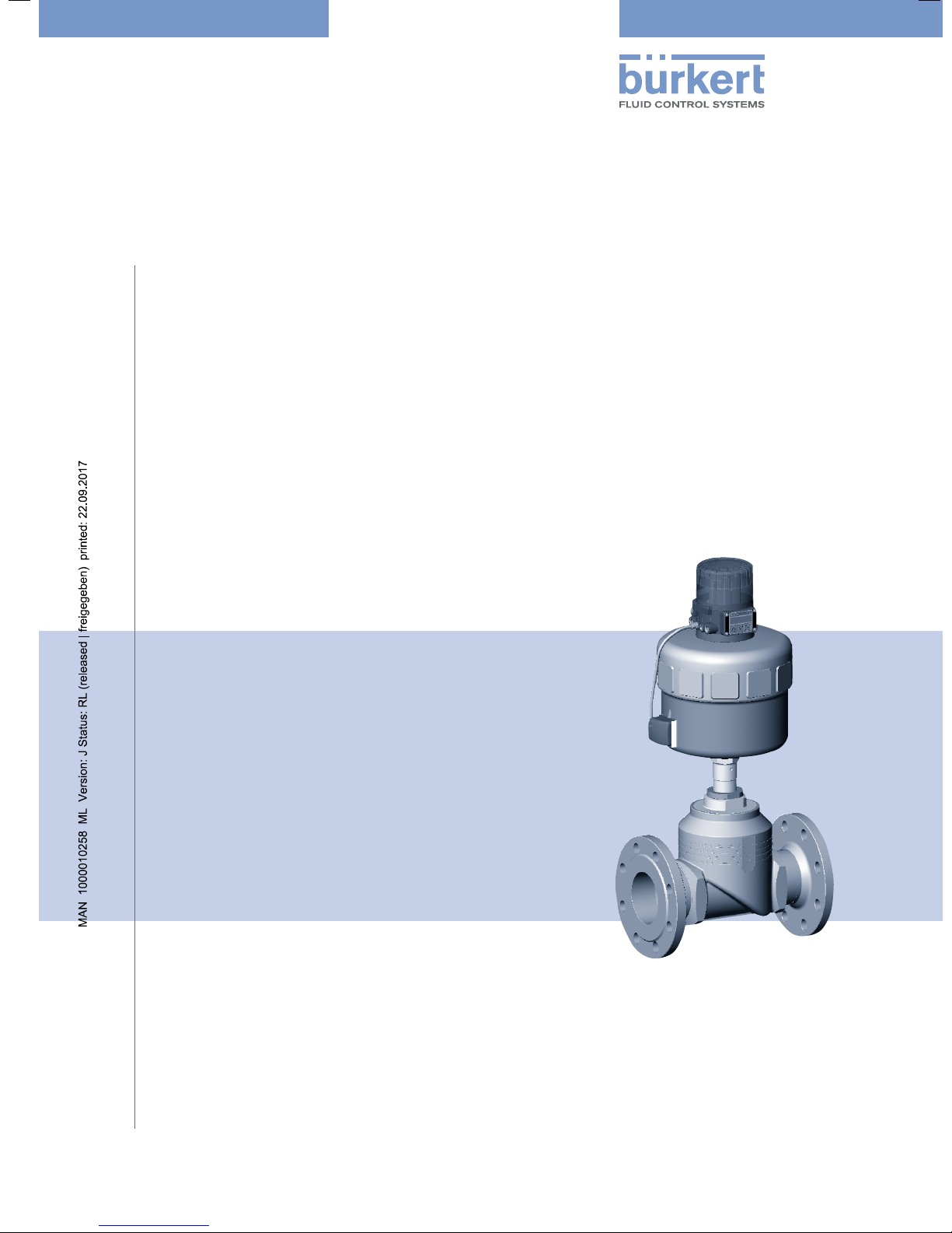
Type 2712
Piston controlled flat-seat valve
Kolbengesteuertes Geradsitzventil
Soupape à tête droite commandée par piston
Actuator sizes 175 mm - 225 mm
Nominal diameters DN 65, DN 80, DN 100
Antriebsgrößen 175 mm - 225 mm
Nennweiten DN 65, DN 80, DN 100
Tailles de mécanisme 175 mm - 225 mm
Diamètre nominal DN 65, DN 80, DN 100
Operating Instructions
Bedienungsanleitung
Manuel d‘utilisation
Page 2
We reserve the right to make technical changes without notice.
Technische Änderungen vorbehalten.
Sous réserve de modifications techniques.
© Bürker t Werke GmbH & Co. KG, 200 - 2017
Operating Instructions 1706/_EU-EN_008 / Original DE
Page 3

C
ONTENTS
Contents of the
overall operating instructions for the
Piston controlled flat-seat valve
Actuator sizes 175 - 225 mm
Nominal diameters DN 65, DN 80, DN 100
GENERAL NOTES ............................................................................................................................................................................................................................... 3
Symbols .................................................................................................................................................................................................................................................. 4
Safety information ................................................................................................................................................................................................................... 4
Scope of delivery....................................................................................................................................................................................................................... 4
Warranty conditions.............................................................................................................................................................................................................. 4
TECHNICAL DATA ............................................................................................................................................................................................................................. 5
Construction of the control valve ..................................................................................................................................................................... 6
Media ........................................................................................................................................................................................................................................................... 6
COMISSIONING........................................................................................................................................................................................................................................ 7
Installation........................................................................................................................................................................................................................................... 8
MAINTENANCE AND SERVICING ........................................................................................................................................................................... 9
english
Malfunctions................................................................................................................................................................................................................................. 10
Replacing the control cone..................................................................................................................................................................................... 10
Replacement of valve seat ....................................................................................................................................................................................... 12
Spare parts sets for standard valves ....................................................................................................................................................... 13
2712 big - 1
Page 4
C
ONTENTS
english
2 - 2712 big
Page 5

GENERAL
NOTES
GENERAL NOTES
english
Symbols
Safety notes
Scope of delivery
Warranty conditions
..................................................................................................................................................................................................................................................
......................................................................................................................................................................................................................................
.......................................................................................................................................................................................................................
..............................................................................................................................................................................................................
4
4
4
4
2712 big - 3
Page 6
GENERAL NOTES
Symbols
The following symbols are used in these operating instructions:
marks a work step thet you must carry out.
ATTENTION!
NOTE
hsilgne
Safety notes
Please observe the notes in these operating instructions together with the conditions of use and permitted
data that are specified in the data sheets for the pneumatically actuated valve and for the Top
order that the device will function perfectly and remain operable for a long time:
• Keep to standard engineering rules in planning the use of and operating the device!
• Installation and maintenance work are only allowed by specialist personnel using suitable tools!
• Observe the current regulations on accident prevention and safety for electrical devices during
operation and maintenance of the device!
• Switch off the supply voltage in all cases before intervening in the system!
• Note that in systems under pressure, piping and valves may not be loosened!
• Take suitable precautions to prevent inadvertent operation or damage by unauthorized action!
• Make sure that after an interruption to the electrical or pneumatic supply, the process starts up again in
a well-defined, controlled manner!
• Read the safety notes for the electrical part in the operating instructions for the Top
• On non-observance of these notes and unauthorized interference with the device, we will refuse all
liability and the warranty on device and accessories will become void!
marks notes on whose non-observance your health or the functioning of the device will
be endangered.
marks important additional information, tips and recommendations.
Control
Control
.
, in
Scope of delivery
Immediately after receipt of a shipment, make sure that the contents are undamaged and match the
scope of delivery stated on the packing slip.
If there are discrepancies, please contact immediately our customer service:
Bürkert Fluid Control Systems
Sales Center
Christian-Bürkert-Str. 13-17
D-76453 Ingelfingen
Tel.: +49 (0) 7940 - 10 91 111
Fax: +49 (0) 7940 - 10 91 448
E-Mail: info@de.buerkert.com
Warranty conditions
This document contains no warranty statements. In this connection we refer to our general sales and
business conditions. A prerequisite for validity of the warranty is use of the device as intended with
observance of the specified conditions of use.
ATTENTION!
The warranty covers only faultless condition of the valve Type 2712 with pneumatic
actuator and the TopControl. No liability will be accepted for consequential damage of
any kind that may arise from failure or malfunctioning of the device.
4 - 2712 big
Page 7

TECHNICAL
DATA
TECHNICAL DATA
english
Construction of the control valve
Media
...........................................................................................................................................................................................................................................................
.....................................................................................................................................................................
6
6
2712 big - 5
Page 8
TECHNICAL DATA
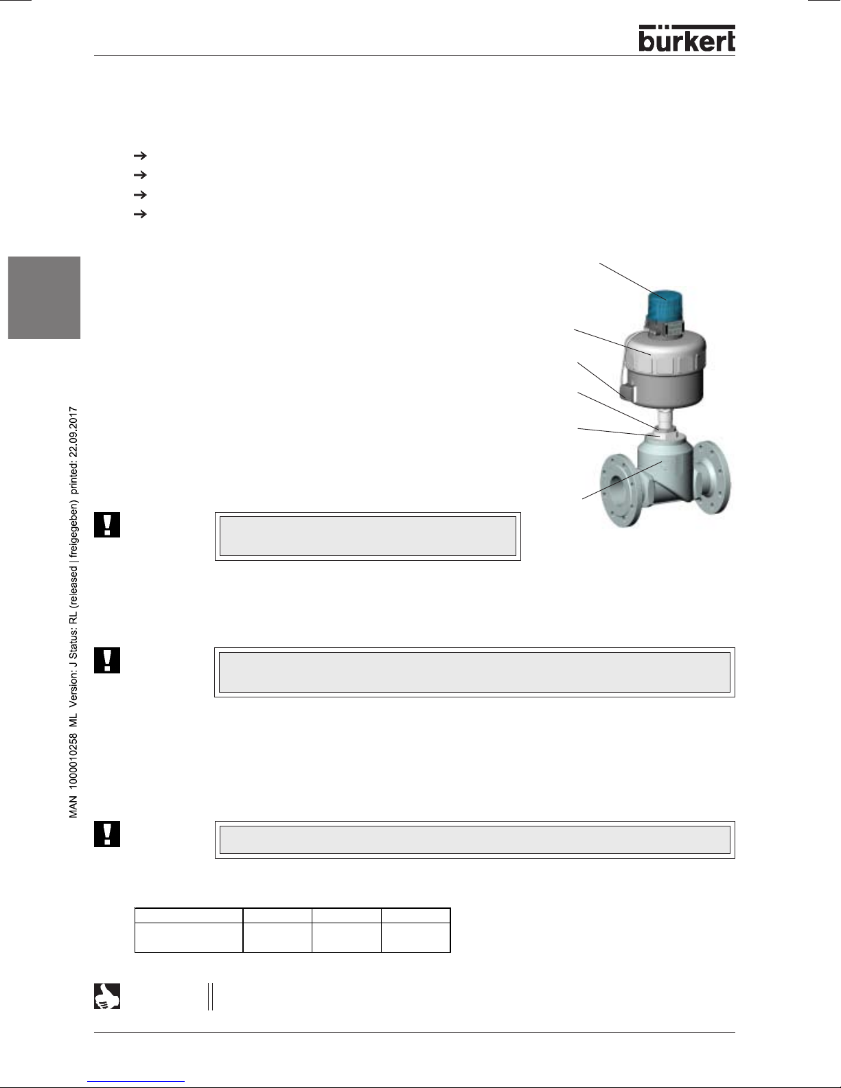
Construction of the control valve
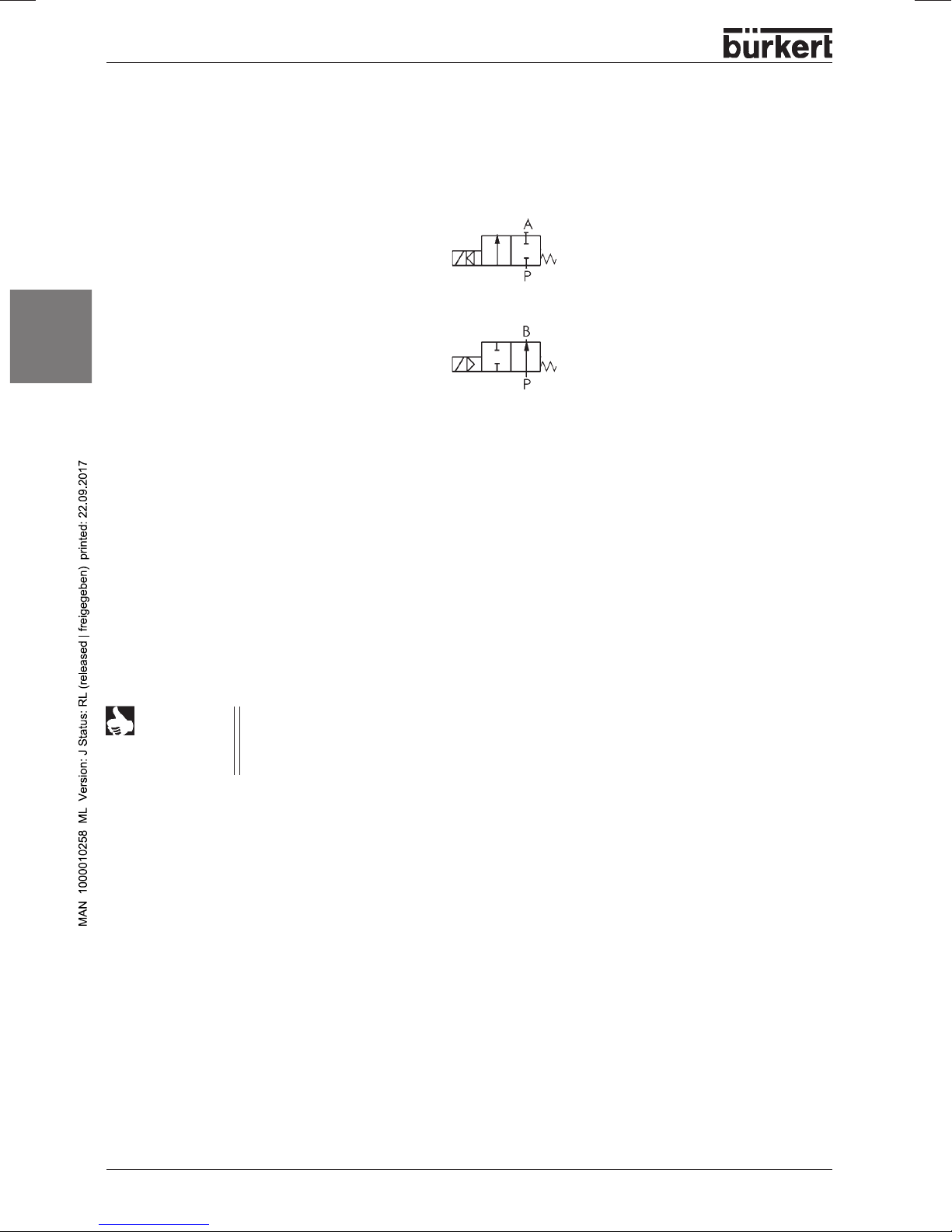
2/2-way piston controlled valv e with control cone and Y-housing.
Control function A
(closed by spring force in rest position)
Control function B
(open in rest position)
english
Actuator material: P A (polyamide)
Housing material: stainless steel 316L
Seal materials: steel/steel (1.4571) or PTFE/steel
Media
Liquid and gaseous media are suitable that do not attack the housing and seal materials.
Control medium: instrument air , Class 3 to DIN ISO 8573-1
NOTE
The approved operating pressures and media temperatures are to be taken from the data
sheet or rating plate. With regard to the permissible seat leakage r ate, the v alues specified
in DIN EN 1349 are complied with, whereby for the steel/steel seal, leakage class IV
applies, and for the PTFE/steel seal, leakage class VI applies.
6 - 2712 big
Page 9

COMMISSIONING
COMMISSIONING
english
Installation of the valve
.........................................................................................................................................................................................................
8
2712 big - 7
Page 10
COMMISSIONING
Installation of the valve
Installation in any orientation, but preferably with the actuator above.
Observe the direction of flow: with control valves the general rule is: inlet under seat!
Clean piping from contamination!
Before attaching the valve housing, make sure the piping is aligned!
If the housing is to be welded on, make absolutely sure that the drive unit is removed beforehand.
Procedure:
1. Remove the electrical and pneumatic supplies from the
Top
Control
2. Pull off the pneumatic hose between Top
english
at the control port of the latter.
3.
Control function A:
Pressurize the lower control port of the actuator with
compressed air (6 bar), so that the control cone is lifted from
the valve seat and is not damaged.
Control function B:
With control function B, no compressed air m ust be applied
for this purpose.
4. Remove the actuator in the open valve position by
unscrewing the threaded nipple (SW70) from the housing.
A TTENTION!
.
Do
not
loosen the screw (SW65) above the
threaded nipple!
Control
and actuator
Top
Control
actuator
lower
control port
screw
(SW65)
threaded nipple
(SW70)
housing
5. Before reinstalling the actuator (in the open valve position), grease the nipple thread with
stainless steel lubricant, e.g. Klüberpaste UH1 96-402 from Messrs. Klüber and replace
the graphite seal.
A TTENTION!
For special applications such as for oxygen and analysis, use only the approved
lubricants.
6 . After tightening the threaded nipple (observe torque), the actuator can be aligned as required.
For this purpose, unscrew the screw (SW65) above the threaded nipple ca. a half-turn and bring the
actuator into the desired position.
Then retighten the screw with a torque of 100 ± 5 Nm.
A TTENTION!
During this operation, the valve must also be in the open position.
Tightening torques for the threaded nipple (SW70)
DN 65 80 100
Tight eni ng torque
[Nm]
100 ± 5 120 ± 5 150 ± 5
NOTE
For applications in aggressive media, we recommaend attaching all free pneumatic
connections to a pneumatic hose whose other end lies in a neutral atmosphere.
8 - 2712 big
Page 11
MAINTENANCE AND SERVICING
MAINTENANCE AND
SERVICING
Malfunctions
Replacing the control cone
Replacement of valve seat
Spare parts sets
.................................................................................................................................................................................................................................
......................................................................................................................................................................................................................
.....................................................................................................................................................................................
.......................................................................................................................................................................................
english
10
10
12
13
2712 big - 9
Page 12
MAINTENANCE AND SERVICING
Malfunctions
Possible malfunctions concerning the actuator are listed in the operatinginstructions for the Top
ATTENTION!
Repairs to the actuator may only be carried out in the factory. Contact your Bürkert
branch or our Customer Service directly:
hsilgne
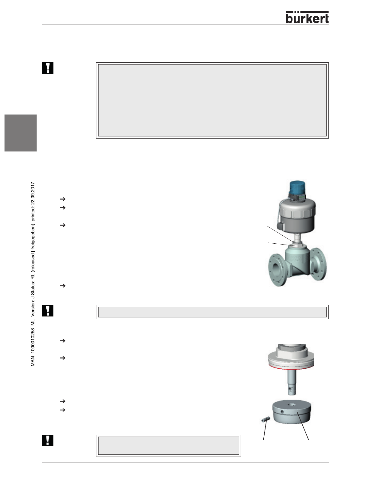
Replacing the control cone
On the fluidic side, the control cone can be replaced in case of wear or damage. For this purpose, the
actuator must be disassembled from the housing.
Disassembly
Remove the electrical and pneumatic supplies from the Top
Pull off the pneumatic hose between Top
control port of the latter.
Control function A:
Pressurize the lower control port of the actuator with compressed
air (6 bar), so that the control cone is liftet from the valve seat and
is not damaged.
Control function B:
With control function B, no compressed air must be applied for this
purpose.
Remove the actuator in the open valve position by unscrewing the
threaded nipple (SW70) from the housing.
Bürkert Fluid Control Systems
Sales Center
Christian-Bürkert-Str. 13-17
D-76453 Ingelfingen
Tel.: +49 (0) 7940 - 10 91 111
Fax: +49 (0) 7940 - 10 91 448
E-Mail: info@de.buerkert.com
Control
Control
and actuator at the
.
screw
(SW65)
threaded nipple
(SW70)
Control
.
ATTENTION!
Do
not
loosen the screw (SW65) above the threaded nipple!
Replacing the control cone:
Knock out the dowel pin with a suitable driver.
Driver diameter Ø 8 mm
Pull off the control cone with the aid of two metal strips of equal
height that are clamped to the left and right of the spindle between
the control cone and the threaded nipple of the actuator. To pull off
the control cone, apply compressed air (approx. 6 bar) to the lower
control connection of the actuator.
Place the new control cone onto the end of the spindle.
Align the bores to each other.
ATTENTION!
10 - 2712 big
Do not damage the sealing surface or the control
contour!
dowel pin control
cone
Page 13
MAINTENANCE AND SERVICING
Assembly
Support the control cone at ists cylindrical part with the aid of a V-block or the lik e.
Place the dowel pin in postion and carefully knock in with a hammer .
Bring the dowel pin into a central position relative to the spindle axis (knock it in up to the end of the
recess).
Before reinstalling the actuator (in the open valve position), grease the nipple thread with stainless
steel lubricant, e.g. Klüberpaste UH1 96-402 from Messrs. Klüber and replace the graphite seal.
A TTENTION!
After tightening the threaded nipple (SW70) (observe torque), the actuator can be aligned as required.
For this purpose, unscrew the screw (SW65) above the threaded nipple ca. a half-turn and bring the
actuator into the desired position.
Then retighten the screw with a torque of 100 ± 5 Nm an.
A TTENTION!
For special applications such as for oxygen and analysis, use only the approved
lubricants.
During this operation, the valve must also be in the open position.
english
2712 big - 11
Page 14
MAINTENANCE AND SERVICING
Replacement of valve seat
To replace the valv e seat, the actuator must be disassemb led from the housing. F or disassemb ly and
assembly, see "Replacing the control cone".
Unscrew the old housing seat using the assembly tool and a
spanner.
Clean thread and sealing surface in the housing with compressed
air.
Select a tool insert and screw it into the assembly tool.
Push the new seat onto the assembly tool, grease the thread with
stainless steel lubricant, e.g. Klüberpaste UH1 96-402 from
Messrs. Klüber.
english
A TTENTION!
Place the attached seat by hand into the housing thread and
screw it in.
Tighten the seat with a torque wrench to the torque specified.
For special applications such as for oxygen and
analysis, use only the approved lubricants.
assembly tool
tool insert
(to match the nominal
diameter of seat)
valve seat
NOTE
On installing a valve seat with a different nominal
diameter, the order number f or the valve changes!
Tightening torques for seat assembly
Seat assembly tools
Housing DN Order no.
DN Torque
[Nm]
65 150
80 180
100 220
+10
+10
+10
15 652 604
20 652 605
25 652 606
12 - 2712 big
32 652 607
40 652 608
50 652 609
Page 15

MAINTENANCE AND SERVICING
Spare parts sets for standard valves
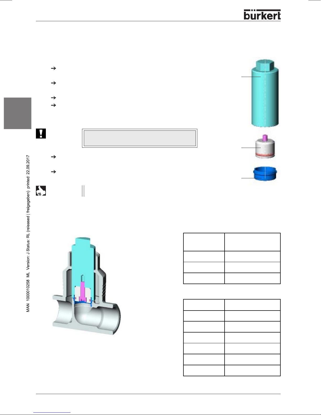
A control cone set, a control fittings set and a set of seals (packed gland) are av ailab le as spares. To
disassemble the actuator fromt he housing or reassemble it, proceed as under installation.
NOTE
Before disassembling or opening the device,
release the pressure in the piping system.
screw SW 65
threaded nipple SW 70
control cone set
SET 6
always
interrupt the supply of medium and
set of seals
(packed gland)
SET 5
control fittings set
SET 6
actuator
english
NOTE
Spare parts sets for special versions are availab le on
request (e.g. oxygen or analysis versions, etc.)
2712 big - 13
Page 16

MAINTENANCE AND SERVICING
Control cone set
hsilgne
Valve seat set
DN
housing
65 40 Ø175 155 625 155 637
65 50 Ø175 155 627 155 639
65 65 Ø175 155 630 155 642
80 50 Ø225 155 628 155 640
80 65 Ø225 155 631 155 643
80 80 Ø225 155 633 155 645
100 65 Ø225 155 632 155 644
100 80 Ø225 155 634 155 646
100 100 Ø225 155.635 155 647
Contains:
Control cone, dowel pin, graphite seal
DN DN
Housing Seat Order no.
65 40 262 202
65 50 262 203
65 65 262 204
80 50 262 205
80 65 262 206
80 80 262 207
100 65 262 208
100 80 262 209
100 100 262 210
Contains: Valve seat, O-ring,
DN
seat
graphite seal
Actuator
size
Steel/Steel PTFE/steel
Order no. Order no.
NOTE
Valve seat sets are available on request, please contact your
Set of seals
(packed gland)
14 - 2712 big
DN housing Order no.
65 155 483
80 155 484
100 155 485
Contains:
packed gland module, housing seals
Page 17

INHALT
Inhaltsverzeichnis der
Gesamtbedienungsanleitung des
kolbengesteuerten Geradsitzregelventils
mit Antriebsgrößen 175 mm und 225 mm
und Nennweiten DN 65, DN 80, DN 100
ALLGEMEINE HINWEISE
Darstellungsmittel
Sicherheitshinweise
Lieferumfang
..................................................................................................................................................................................................................................
Garantiebestimmungen
TECHNISCHE DATEN
Aufbau des Regelventils
Medien
.....................................................................................................................................................................................................................................................
INBETRIEBNAHME
Einbau
....................................................................................................................................................................................................................................................
....................................................................................................................................................................................................
................................................................................................................................................................................................................
..........................................................................................................................................................................................................
...............................................................................................................................................................................................
..............................................................................................................................................................................................................
.............................................................................................................................................................................................
.......................................................................................................................................................................................................................
INSTANDHALTUNG UND WARTUNG
...........................................................................................................................................................
17
18
18
18
18
19
20
20
21
22
23
deutsch
Störungen
........................................................................................................................................................................................................................................
Austausch des Regelkegels
Austausch des Ventilsitzes
Ersatzteilsätze für Standardventile
....................................................................................................................................................................................
.....................................................................................................................................................................................
............................................................................................................................................................
2712 big - 15
24
24
26
27
Page 18

INHALT
deutsch
16 - 2712 big
Page 19

ALLGEMEINE HINWEISE
ALLGEMEINE
HINWEISE
deutsch
Darstellungsmittel
Sicherheitshinweise
Lieferumfang
Garantiebestimmungen
................................................................................................................................................................................................................
............................................................................................................................................................................................................
................................................................................................................................................................................................................................
...............................................................................................................................................................................................
18
18
18
18
2712 big - 17
Page 20

ALLGEMEINE HINWEISE
Darstellungsmittel
In dieser Betriebsanleitung werden folgende Darstellungsmittel verwendet:
markiert einen Arbeitsschritt, den Sie ausführen müssen
ACHTUNG!
HINWEIS
kennzeichnet Hinweise, bei deren Nichtbeachtung Ihre Gesundheit oder die Funktionsfähigkeit des Gerätes gefährdet ist
kennzeichnet wichtige Zusatzinformationen, Tipps und Empfehlungen
Sicherheitshinweise
Bitte beachten Sie die Hinweise dieser Betriebsanleitung sowie die Einsatzbedingungen und zulässigen
hcstued
Daten, die in den Datenblättern des Ventils mit pneumatischem Antrieb und des Top
sind, damit das Gerät einwandfrei funktioniert und lange einsatzfähig bleibt:
• Halten Sie sich bei der Einsatzplanung und dem Betrieb des Gerätes an die allgemeinen Regeln der
Technik!
• Installation und Wartungsarbeiten dürfen nur durch Fachpersonal und mit geeignetem Werkzeug erfolgen!
• Beachten Sie die geltenden Unfallverhütungs- und Sicherheitsbestimmungen für elektrische Geräte
während des Betriebes und der Wartung des Gerätes!
• Schalten Sie vor Eingriffen in das System in jedem Fall die Spannung ab!
• Beachten Sie, daß in Systemen, die unter Druck stehen, Leitungen und Ventile nicht gelöst werden dürfen!
• Treffen Sie geeignete Maßnahmen, um unbeabsichtigtes Betätigen oder unzulässige Beeinträchtigung
auszuschließen!
• Gewährleisten Sie nach einer Unterbrechung der elektrischen oder pneumatischen Versorgung einen
definierten und kontrollierten Wiederanlauf des Prozesses!
• Entnehmen Sie die Sicherheitshinweise zum elektrischen Teil der Bedienungsanleitung des Top
• Bei Nichtbeachtung dieser Hinweise und unzulässigen Eingriffen in das Gerät entfällt jegliche Haftung
unsererseits, ebenso erlischt die Garantie auf Geräte und Zubehörteile!
Control
spezifiziert
Control
Lieferumfang
Überzeugen Sie sich unmittelbar nach Erhalt der Sendung, daß der Inhalt nicht beschädigt ist und mit
dem auf dem beigelegten Packzettel angegebenen Lieferumfang übereinstimmt.
Bei Unstimmigkeiten wenden Sie sich bitte umgehend an unseren Kundenservice:
Bürkert Fluid Control Systems
Sales Center
Christian-Bürkert-Str. 13-17
D-76453 Ingelfingen
Tel.: +49 (0) 7940 - 10 91 111
Fax: +49 (0) 7940 - 10 91 448
E-Mail: info@de.buerkert.com
Garantiebestimmungen
Diese Druckschrift enthält keine Garantiezusagen. Wir verweisen hierzu auf unsere allgemeinen Verkaufsund Geschäftsbedingungen. Voraussetzung für die Garantie ist der bestimmungsgemäße Gebrauch des
Gerätes unter Beachtung der spezifizierten Einsatzbedingungen.
ACHTUNG!
18 - 2712 big
Die Gewährleistung erstreckt sich nur auf die Fehlerfreiheit des Ventils Typ 2712 mit pneumatischem Antrieb und des Top
schäden jeglicher Art, die durch Ausfall oder Fehlfunktion des Gerätes entstehen könnten.
Control
. Es wird jedoch keine Haftung übernommen für Folge-
Page 21

TECHNISCHE DATEN DES VENTILS
TECHNISCHE
DATEN
deutsch
Aufbau des Regelventils
Medien
...................................................................................................................................................................................................................................................
.............................................................................................................................................................................................
20
20
2712 big - 19
Page 22

TECHNISCHE DATEN DES VENTILS
Aufbau des Regelventils
2/2-Wege-K olbensteuerventil mit Regelkegel und Schrägsitzgehäuse
Steuerfunktion A
(in Ruhestellung durch Federkraft geschlossen)
Steuerfunktion B
(in Ruhestellung geöffnet)
Antriebswerkstoff: P A (P olyamid)
Gehäusewerkstoff: Edelstahl 316L
Dichtwerkstoffe: Stahl/Stahl (1.4571) oder PTFE/Stahl
deutsch
Medien
Flüssige u. gasförmige Medien, die den Gehäuse- und Dichtwerkstoff nicht angreifen.
Steuermedium: Instrumentenluft, Klasse 3 nach DIN ISO 8573-1
HINWEIS
Die zugelassenen Betriebsdrücke und Medientemperaturen sind dem Datenblatt bzw . dem
T ypschild zu entnehmen. Hinsichtlich der zulässigen Sitzleckage werden die in der DIN EN
1349 angegebenen Werte eingehalten, wobei für die Stahl/Stahl-Abdichtung die Leckageklasse IV und für die PTFE/Stahl-Adichtung die Leckageklasse VI zutrifft.
20 - 2712 big
Page 23

INBETRIEBNAHME DES VENTILS
INBETRIEBNAHME
deutsch
Einbau des Ventils
.....................................................................................................................................................................................................................
22
2712 big - 21
Page 24

INBETRIEBNAHME DES VENTILS
Einbau des Ventils
Einbaulage beliebig, bevorzugt Antrieb nach oben.
Beachten Sie die Durchflußrichtung, bei Regelventilen gilt generell: Anströmung unter Sitz!
Säubern Sie die Rohrleitungen von V erunreinigungen!
Achten Sie vor Anschluß des Ventilgehäuses auf fluchtende Rohrleitungen!
Entfernen Sie bei Schweißgehäusen den Antrieb unbedingt vor dem Einschweißen des Gehäuses.
Vorgehensweise:
1. Entfernen Sie die elektrische u. pneumatische V ersorgung
deutsch
ACHTUNG!
vom T op
2. Ziehen Sie den Pneumatikschlauch zwischen Top
Antrieb am Steueranschluß desAntriebes ab.
3.
Steuerfunktion A:
Beaufschlagen Sie den unteren Steueranschluß des
Antriebes mit Druckluft (6 bar), damit der Regelkegel vom
V entilsitz abhebt und nicht beschädigt wird.
Steuerfunktion B:
Bei Steuerfunktion B muss hierzu keine Druckluft angelegt
werden.
4. Entfernen Sie den Antrieb in offener Ventilstellung durch Losschrauben des Gewindenippels (SW70) vom Gehäuse.
Control
Lösen Sie
Gewindenippels!
.
nicht
die Schraube (SW65) oberhalb des
Control
und
Top
Control
Antrieb
unterer
Steueranschluss
Schraube
(SW65)
Gewindenippel
(SW70)
Gehäuse
5. Fetten Sie vor Wiedereinbau des Antriebes (in off ener V entilstellung) das Nippelge winde mit
Edelstahlschmierstoff ein, z.B. Klüberpaste UH1 96 - 402 der Firma Klüber und erneuern Sie die
Graphitdichtung.
ACHTUNG!
V erwenden Sie bei spezifischen Anwendungen, z.B. Sauerstoff-, Analyseanwendungen
nur zugelassene Schmierstoffe
6 . Nach dem Festziehen des Gewindenippels (Drehmomente beachten), kann der Antrieb bei Bedarf
ausgerichtet werden.
Hierfür lösen Sie die Schraube (SW65) oberhalb des Gewindenippels ca. eine
halbe Drehung und bringen den Antrieb in die gewünschte Position.
Ziehen Sie danach die Schraube wieder mit 100 ± 5 Nm an.
ACHTUNG!
Das Ventil muss sich hierzu ebenf alls in der geöffneten Stellung befinden.
Anzugsmomente für den Gewindenippel (SW70)
DN 65 80 100
Anzugs moment
[Nm]
100 ± 5 120 ± 5 150 ± 5
HINWEIS
Bei Einsatz in aggressiver Umgebung empf ehlen wir, sämtliche freien Pneumatikanschlüsse
mit Hilfe eines Pneumatikschlauches in neutrale Atmosphäre abzuleiten.
22 - 2712 big
Page 25

INSTANDHALTUNG UND WARTUNG DES VENTILS
INSTANDHALTUNG
UND
WARTUNG
deutsch
Störungen
Austausch des Regelkegels
Austausch des Ventilsitzes
Ersatzteilsätze für Standardventile
........................................................................................................................................................................................................................................
..................................................................................................................................................................................
.....................................................................................................................................................................................
............................................................................................................................................................
24
24
26
27
2712 big - 23
Page 26

INSTANDHALTUNG UND WARTUNG DES VENTILS
Störungen
Mögliche Störungen seitens der Ansteuerung sind in der Bedienungsanleitung des T op
ACHTUNG!
Reparaturen am Antrieb dürfen nur im Werk durchgeführt werden. Wenden Sie sich hierzu
an Ihre Bürkert Niederlassung oder direkt an unseren Kundenservice:
Austausch des Regelkegels
hcstued
Auf der fluidischen Seite besteht die Möglichkeit bei Verschleiß oder bei Beschädigung den Regelkegel zu
tauschen. Hierzu muß der Antrieb vom Gehäuse demontiert werden.
Demontage
Entfernen Sie die elektrische u. pneumatische Versorgung vom
.
Control
Top
Ziehen Sie den Pneumatikschlauch zwischen Top
trieb am Steueranschluß des Antriebes ab.
Steuerfunktion A:
Beaufschlagen Sie den unteren Steueranschluß des Antriebes mit
Druckluft (6 bar), damit der Regelkegel vom Ventilsitz abhebt und
nicht beschädigt wird.
Steuerfunktion B:
Bei Steuerfunktion B muss hierzu keine Druckluft angelegt werden.
Entfernen Sie den Antrieb in offener Ventilstellung durch Losschrauben des Gewindenippels (SW70) vom Gehäuse.
Bürkert Fluid Control Systems
Sales Center
Christian-Bürkert-Str. 13-17
D-76453 Ingelfingen
Tel.: + 49 (0) 7940 - 10 91 111
Fax: + 49 (0) 7940 - 10 91 448
E-Mail: info@de.buerkert.com
Control
und An-
Schraube
(SW65)
Gewindenippel
(SW70)
Control
aufgeführt.
ACHTUNG!
Lösen Sie
nicht
Regelkegel tauschen:
Klopfen Sie den Spannstift mit einem passenden Splinttreiber
heraus.
Durchmesser des Splinttreibers Ø 8 mm
Ziehen Sie den Regelkegel mit Hilfe zweier gleich hoher Metalleisten ab, die links und rechts der Spindel zwischen den Regelkegel und den Gewindenippel des Antriebes geklemmt werden.
Geben Sie zum Abziehen des Regelkegels auf den unteren Steueranschluß des Antriebes Druckluft (6 bar).
Stecken Sie den neuen Regelkegel auf das Spindelende.
Richten Sie die Bohrungen zueinander aus.
ACHTUNG!
24 - 2712 big
Dichtfläche und Regelkontur des Regelkegels dürfen
nicht beschädigt werden!
die Schraube (SW65) oberhalb des Gewindenippels!
Spannstift Regelkegel
Page 27

INSTANDHALTUNG UND WARTUNG DES VENTILS
Montage
Stützen Sie den Regelkegel an seinem zylindrischen Teil mit Hilfe eines Prismas oder ähnlichem ab.
Setzen Sie den Spannstift an und klopfen Sie ihn vorsichtig mit dem Hammer ein.
Bringen Sie den Spannstift in zur Spindelachse gesehen mittige Lage (klopfen Sie ihn bis zum Ende
der Ansenkung ein).
Fetten Sie vor Wiedereinbau des Antriebes (in offener V entilstellung) das Nippelgewinde mit Edelstahlschmierstoff ein, z.B. Klüberpaste UH1 96-402 der Firma Klüber , und erneuern Sie die Graphitdichtung.
ACHTUNG!
Nach dem Festziehen des Gewindenippels (SW70) (Drehmomente beachten), kann der Antrieb bei
Bedarf ausgerichtet werden. Hierfür lösen Sie die Schraube (SW65) oberhalb des Gewindenippels ca.
eine halbe Drehung und bringen den Antrieb in die gewünschte Position. Ziehen Sie danach die Schraube wieder mit 100 ± 5 Nm an.
ACHTUNG!
V erwenden Sie bei spezifischen Anwendungen, z.B. Sauerstoff-, Analyseanwendungen,
nur zugelassene Schmierstoffe
Das Ventil muss sich hierzu ebenf alls in der geöffneten Stellung befinden.
deutsch
2712 big - 25
Page 28

INSTANDHALTUNG UND WARTUNG DES VENTILS
Austausch des Ventilsitzes
Zum Austausch des V entilsitzes muß der Antrieb vom Gehäuse demontiert werden. Demontage und Montage siehe "Austausch des Regelkegels"
Schrauben Sie den alten Gehäusesitz mit Hilfe des
Montagewerkzeuges und einem Schraubenschlüssel aus.
Säubern Sie Gewinde und Dichtfläche im Gehäuse mit Preßluft.
Wählen Sie einen W erkzeugeinsatz aus und schrauben Sie ihn
in das Montagewerkzeug ein.
Stecken Sie den neuen Sitz auf das Montagewerkzeug, fetten
Sie das Gewinde mit Edelstahlschmierstoff ein, z.B.
Klüberpaste UH1 96 - 402 der Firma Klüber.
Montagewerkzeug
ACHTUNG!
deutsch
HINWEIS
V erwenden Sie bei spezifischen Anwendungen,
z.B. Sauerstoff-, Analyseanwendungen, nur zugelassene Schmierstoffe
Setzen Sie den aufgesteckten Sitz von Hand in das Gehäusegewinde und schrauben Sie ihn ein.
Ziehen Sie den Sitz mit Hilfe eines Drehmomentschlüssels auf
das angegebene Drehmoment an.
Bei Einbau eines V entilsitz es mit anderer Nennweite,
ändert sich die Bestellnummer für das V entil!
Anzugsmomente für die Sitzmontage
Werkzeugeinsatz
(je nach Sitz-
nennweite)
Ventilsitz
DN Anzugsmoment
[Nm]
65 150
80 180
100 220
+10
+10
+10
26 - 2712 big
Sitzmontagewerkzeuge
Gehäuse-DN Best.-Nr.
65 655 562
80 655 563
100 655 564
Page 29

INSTANDHALTUNG UND WARTUNG DES VENTILS
Ersatzteilsätze für Standardventile
Als Ersatzteile steht ein Regelkegelsatz, eine Regelgarnitur und ein Dichtungssatz Stopfbuchse zur
V erfügung. Zur Demontage bzw . Montage des Antriebes vom Gehäuse gehen Sie wie unter dem Punkt
Einbau beschrieben vor.
HINWEIS
Unterbrechen Sie vor dem Ausbau oder dem Öffnen des Gerätes
und bauen Sie den Druck im Leitunssystem ab.
Antrieb
Schraube SW 65
Gewindenippel SW 70
immer
die Mediumszufuhr
deutsch
HINWEIS
Ersatzteilsätze für Sonderausführungen erhalten Sie auf Anfrage
(z. B . Sauerstoff-, Analyseausfürungen usw .).
2712 big - 27
Page 30

INSTANDHALTUNG UND WARTUNG DES VENTILS
hcstued
Regelkegelsatz
Ventilsitzsatz
DN
Gehäuse
65 40 Ø175 155 625 155 637
65 50 Ø175 155 627 155 639
65 65 Ø175 155 630 155 642
80 50 Ø225 155 628 155 640
80 65 Ø225 155 631 155 643
80 80 Ø225 155 633 155 645
100 65 Ø225 155 632 155 644
100 80 Ø225 155 634 155 646
100 100 Ø225 155.635 155 647
Beinhaltet:
Regelkegel, Spannstift, Graphitdichtung
DN DN
Gehäuse Sitz Best-Nr.
65 40 262 202
65 50 262 203
65 65 262 204
80 50 262 205
80 65 262 206
80 80 262 207
100 65 262 208
100 80 262 209
100 100 262 210
Beinhaltet: Ventilsitz, O-Ring,
DN Sitz Antriebs-
Graphitdichtung
Stahl/Stahl PTFE/Stahl
größe
Best.-Nr. Best.-Nr.
HINWEIS
Ventilsitzsätze erhalten Sie auf Anfrage über Ihre Bürkert-Vertriebsniederlassung.
Dichtungssatz
Stopfbuchse
28 - 2712 big
DN Gehäuse Bestell-Nr.
65 155 483
80 155 484
100 155 485
Beinhaltet:
Modul Stopfbuchse, Gehäusedichtungen
Page 31

TABLE DES MATIÈRES
Table des matières des instructions
de service complètes de la soupape à tête
droite commandée par piston
Tailles de mécanisme 175 mm et 225 mm
Diamètre nominal DN 65, DN 80, DN 100
REMARQUES GENERALES
Représentation
.........................................................................................................................................................................................................................
..........................................................................................................................................................................................
Consignes générales de sécurité
Fourniture
Clauses de garantie
........................................................................................................................................................................................................................................
...........................................................................................................................................................................................................
CARACTÉRISTIQUES TECHNIQUES
Structure de la soupape de réglage
Fluides
MISE EN SERVICE
Montage
MAINTENANCE ET ENTRETIEN
...................................................................................................................................................................................................................................................
..........................................................................................................................................................................................................................
.................................................................................................................................................................................................................................................
...........................................................................................................................................................................
....................................................................................................................................................................
............................................................................................................................................................
.............................................................................................................................................................
31
32
32
32
32
33
34
34
35
36
37
français
Pannes
..................................................................................................................................................................................................................................................
Echange du pointeau de réglage
Echange du siège de la soupape
Jeux de pièces de rechange
....................................................................................................................................................................
....................................................................................................................................................................
..................................................................................................................................................................................
2712 big - 29
38
38
40
41
Page 32

TABLE DES MATIÈRES
français
30 - 2712 big
Page 33

REMARQUES GENERALES
REMARQUES
GENERALES
Représentation
Consignes générales de sécurité
Fourniture
Clauses de garantie
.........................................................................................................................................................................................................................
........................................................................................................................................................................................................................................
...........................................................................................................................................................................................................
..................................................................................................................................................................
32
32
32
32
français
2712 big - 31
Page 34

REMARQUES GENERALES
Représentation
Les symboles de représentation suivants sont utilisés dans cette notice de service:
marque une étape de travail devant être exécutée
ATTENTION!
REMARQUE
caractérise des instructions dont l'inobservation entraîne des risques pour votre santé
ou met en cause la fonctionnalité de l'appareil.
caractérise des informations supplémentaires imprtantes, des conseils et des
recommandations.
Consignes de sécurité
Veuillez tenir compte des consignes de cette notice de service de même que des conditions d'emploi et
données admissibles spécifiées dans les fiches techniques de la soupape à mécanisme pneumatique et
du TopControl afin que l'appareil fonctionne parfaitement et reste longtemps opérationnel.
• S'en tenir aux règles techniques généralement reconnues lors du projet de mise en oeuvre et du
service de l'appareil.
• L'installation et les interventions nécessitées par la maintenance ne doivent être effectuées que par un
siaçnarf
personnel qualifié équipé des outils adéquats.
• Respecter les dispositions en vigueur de prévention des accidents et de sécurité pour appareils
électriques pen
• Toujours couper la tension d'alimentation avant toute intervention dans le système.
• Tenir compte que dans les systèmes sous pression, les conduites et soupapes ne doivent pas être
desserrées.
• Pendre les mesures qui s'imposent pour éviter un actionnement par inadvertance de l'appareil ou une
mise en cause inadmissible de son fonctionnement.
• Assurer un redémarrage défini et contrôlé du processus après une interruption de l'alimentation
électrique ou pneumatique.
• Se référer aux consignes de sécurité de la partie électrique des instructions de service du Top
• En cas d'inobservation de ces consignes et d'interventions non autorisées dans l'appareil, nous
déclinons toute responsabilité de même qu'elles entraînent l'annulation de la garantie sur l'appareil et
les pièces accessoires!
dant le service, la maintenance de l'appareil.
Control
.
Fourniture
Contrôler dès réception de l'envoi que le contenu n'a subi aucun dommage et qu'il correspond bien à la
fourniture figurant sur le bordereau d'envoi.
En cas de non concordance, s'adresser immédiatement à votre succursale Bürkert ou à notre service
après vente:
Bürkert Fluid Control Systems
Sales Center
Christian-Bürkert-Str. 13-17
D-76453 Ingelfingen
Tel.: + 49 (0) 7940 - 10 91 111
Fax: + 49 (0) 7940 - 10 91 448
Clauses de garantie
Ce document ne constitue aucun engagement de garantie. Nous vous renvoyons à cet effet à nos
conditions générales de vente et comerciales. La condition préalable au consentement de la garantie est
l'utilisation conforme de l'appareil à l'usage auquel il est destiné, compte tenu de l'observation des
conditions d'emploi spécifiées.
ATTENTION!
32 - 2712 big
Les prestations de garantie ne s'étendent qu'à l'absence de défaut de la soupape type
2012 à mécanisme pneumatique et au Top
responsabilité pour des dégâts consécutifs de toute nature susceptibles de survenir par
suite de défaillance ou de disfonctionnement de l'appareil.
E-Mail: info@de.buerkert.com
Control
. Nous déclinons, par contre, toute
Page 35

CARACTERISTIQUES TECHNIQUES
CARACTERISTIQUES
TECHNIQUES
Structure de la soupape de réglage
Fluides
...................................................................................................................................................................................................................................................
...........................................................................................................................................................
34
34
français
2712 big - 33
Page 36

CARACTERISTIQUES TECHNIQUES
Structure de la soupape de réglage
Soupape 2/2 voies commandée par piston avec pointeau de réglage et boîtier incliné
Fonction de commande A
(fermée en position de repos par effet de ressort)
Fonction de commande B
(ouverte en position de repos)
Matière du mécanisme: P A (poly amide)
Matière du boîtier: Acier fin 316L
Matières d'étanchéité: Acier/Acier (1.4571) ou PTFE/Acier
Fluides
français
Fluides liquides ou gazeux qui n'attaquent pas la matière du boîtier et celle d'étanchéité
Fluide de commande: air instrumental, classe 3 selon DIN ISO 8573-1
REMARQUE
Les pressions de service et les températures de fluide admises figurent sur la plaque
signalétique. Concernant les fuites admises du siège, les valeurs indiquées dans la norme
DIN EN 1349 sont respectées, compte tenu que pour le joint étanche acier/acier la classe
IV de fuite s'applique et pour le joint PTFE/acier, la classe VI.
34 - 2712 big
Page 37

MISE EN SERVICE
MISE EN SERVICE
Montage de la soupape
......................................................................................................................................................................................................
36
français
2712 big - 35
Page 38

MISE EN SERVICE
Montage de la soupape
Position de montage quelconque , de préférence, mécanisme vers le haut.
T enir compte du sens du débit, pour les soupapes de réglage , l'écoulement a lieu en général sous le
siège!
Nettoyer les tuyauteries des impuretés!
Av ant de raccorder le boîtier de la soupape, v eiller à l'alignement des conduites!
Enlever impérativement le mécanisme avant de souder le boîtier (boîtier à souder).
Mode opératoire:
1. Enlever l'alimentation pneumatique et électrique du
Top
Control
2. Ôter en tirant le tuyau souple pneumatique entre le Top
et le mécanisme au raccord de commande de ce dernier.
3.
Fonction de commande A:
Charger d'air comprimé (6 bars) le raccord inférieur de
commande du mécanisme afin que le pointeau de réglage se
soulève du siège et ne soit pas endommagé.
Fonction de commande B:
Pas de chargement d'air comprimé ne doit être fait pour la
fonction B.
4. Enlever le mécanisme en position ouverte de la soupape, en
français
dévissant le raccord à vis (SW70) du boîtier.
A TTENTION!
.
Ne
desserrer pas la vis (SW65) au-dessus du
raccord à vis.
Control
Top
Control
Mécanisme
Raccord de commande
inférieur
Vis
(SW65)
Raccord à vis
(SW70)
Boîtier
5. Avant de remoter le mécansime (en position ouv erte de la soupape), graisser le raccord à vis av ec
un lubrifiant pour acier fin, p. ex. pâte Klüber UH1 96-402 de la maison Klüber , et renouv eler le joint
graphite.
A TTENTION!
Dans le cas d'applications spécifiques p.ex. applications d'analyse, d'oxygène, utiliser
uniquement des lubrifiants agrées.
6 . Aligner le mécanisme, si nécessaire, après avoir serré à fond le raccord à vis (veiller au couple de
serrage).
A cet effet, desserrer la vis (SW65) au-dessus du raccord à vis d'environ un demi-tour et placer le
mécanisme dans la position souhaitée.
Resserrer ensuite la vis à 100 ± 5 Nm.
A TTENTION!
La soupape doit également se trouver à cet effet en position ouv erte.
Couples de serrage pour le raccord à vis (SW70)
DN 65 80 100
Couple de serrage
[Nm]
REMARQUE
100 ± 5 120 ± 5 150 ± 5
En cas d'utilisation dans un environnement agressif, nous recommandons de dévier tous
les raccordements pneumatiques libres dans une atmosphère neutre à l'aide d'un tuyau
flexible pneumatique.
36 - 2712 big
Page 39

MAINTENANCE ET ENTRETIEN
MAINTENANCE ET
ENTRETIEN
Pannes
Echange du pointeau de réglage
Echange du siège de la soupape
Jeux de pièces de rechange
..................................................................................................................................................................................................................................................
..................................................................................................................................................................................
....................................................................................................................................................................
....................................................................................................................................................................
français
38
38
40
41
2712 big - 37
Page 40

MAINTENANCE ET ENTRETIEN
Pannes
Les pannes susceptibles de survenir du côté de l'excitation figurent dans les instructions de service du
Top
ATTENTION!
Echange du pointeau de réglage
Du côté fluide, il est possible de changer le pointeau de régalge en cas d'usure ou d'endommagement. A
cet effet, le mécanisme doit être démonté du boîtier.
Démontage
Control
.
Les réparations du mécanisme ne doivent être faites qu'en usine. S'adresser à cet effet
à votre succursale Bürkert ou directement à notre service clientèle.
Bürkert Fluid Control Systems
Sales Center
Christian-Bürkert-Str. 13-17
D-76453 Ingelfingen
Tel.: + 49 (0) 7940 - 10 91 111
Fax: + 49 (0) 7940 - 10 91 448
E-Mail: info@de.buerkert.com
siaçnarf
Enlever l'alimentation pneumatique et électrique du T op
Ôther en tirant le tuyau souple pneumatique entre le T op
Control
Control
.
et le
mécanisme au raccord de commande de ce dernier.
Fonction de commande A:
Charger d'air comprimé (6bars) le raccord inférieur de commande du
mécanisme afin que le pointeau de réglage se soulève du siège et
ne soit pas endommagé.
vis
(SW65)
Raccord à vis
(SW70)
Fonction de commande B:
Pas de chargement d'air comprimé ne doit être fait pour la fonction B
Enlever le mécanisme en position ouverte de la soupape, en
dévissant le raccord à vis (SW70) du boîtier.
ATTENTION!
dresserer pas la vis (SW65) au-desus du raccord à vis.
Ne
Echange du pointeau de réglage:
Extraire la goupille à l'aide d'un chasse-goupille adéquat
Diamètre du chasse-goupille Ø 8 mm
Tirer le pointeau à l'aide de deux baguettes métalliques d'égale
longueur à coincer à gauche et à droite de la tige entre le pointeau
et la raccord à vis du mécanisme. Pour tirer le pointeau utiliser de
l'air comprimé (6 bars) sur le raccord inférieur de commande du
mécanisme.
Mettre le nouveau pointeau en place sur le bout de la tige.
Aligner les perçages les uns par rapport aux autres.
ATTENTION!
La surface d'étanchéité et le contour de réglage du
pointeau ne doivent pas être endommagés.
38 - 2712 big
Goupille
élastique
Pointeau de
réglage
Page 41

MAINTENANCE ET ENTRETIEN
Montage
Etayer le pointeau de réglage à sa partie cylindrique à l'aide d'un prisme ou objet similaire.
Mettre la goupille et l'insérer en la tapant prudemment avec le marteau.
Enfoncer la goupille en position médiane regardant l'axe de la broche (l'enfoncer jusqu'au bout du
chanfrein)
Avant de remoter le mécanisme (en position ouv erte de la soupape), graisser le raccord à vis av ec un
lubrifiant pour acier fin, p.ex. pâte Klüber UH1 96-402 de la maison Klüber , et renouveler le joint
graphite en cas de besoin.
A TTENTION!
Le mécanisme peut être aligné, si nécessaire, après avoir serré à fond le raccord à vis (SW70) (veiller
au couple de serrage).
A cet effet, desserrer la vis (SW65) au-dessus du raccord à vis d'environ un demi-tour et mettre le
mécanisme dans la position souhaité. Resserrer ensuite la vis à 100 ± 5 Nm.
A TTENTION!
Dans le cas d'applications spécifiques p.ex. applications d'analyse, d'oxygène, utiliser
uniquement des lubrifiants agrées.
La soupape doit également se trouver à cet effet en position ouv erte.
français
2712 big - 39
Page 42

MAINTENANCE ET ENTRETIEN
Echange du siège de soupape
Pour changer le siège de la soupape, le mécanisme de commande doit être démonté du boîtier . P our le
démontage, voir "Echange du pointeau de réglage".
Dévisser l'ancien siège de boîtier à l'aide de l'outil de montage
et d'une clé à vis.
Nettoyer le pas de vis et la surface d'étanchéité dans le boîtier
à l'air comprimé.
Choisir l'embout d'outil et le visser dans l'outil de montage.
Mettre en place le nouveau siège sur l'outil de montage,
graisser le filetage avec un lubrifiant, p. ex. pâte Klüber UH1
96 - 402 de la maison Klüber.
Outil de montage
A TTENTION!
français
REMARQUE
Dans le cas d'applications spécifiques p. ex.
applications d'analyse, d'oxygène, utiliser
uniquement des lubrifiants agrées.
Introduire le siège monté à la main dans le filet du boîtier et le
visser.
Serrer le siège à l'aide d'une clé dynamométrique au couple
indiqué.
En cas de montage d'un siège de soupape ayant un
autre diamètre nominal, le numéro de commande de
la soupape change!
Couple de serrage pour le montage du siège
Embout d'outil
(suivant diamètre
nominal du siège)
Siège de
soupape
DN Couple de serrage
[Nm]
65 150
80 180
100 220
+10
+10
+10
40 - 2712 big
Outils de montage de siège
DN boitier No. de cde
15 652 604
20 652 605
25 652 606
32 652 607
40 652 608
50 652 609
Page 43

MAINTENANCE ET ENTRETIEN
Jeux de pièces de rechange pour soupapes standard
Sont disponibles comme pièces de rechange, un jeu de pointeaux, une garniture de réglage et un jeu de
joints presse-étoupe. Pour démonter ou monter le mécanisme du boîtier , il f aut procéder comme décrit
dans Montage de la soupape.
REMARQUE
Av ant de démonter ou ouvrir l'appareil, couper impérativement l'arrivée de fluide et
supprimer la pression dans le système de conduites.
Mécanisme
Vis SW 65
Raccord à vis SW 70
Jeu de joints d'étanchéité
Jeu de pointeau
de réglage
SET 6
Presse-étoupe
SET 6
Garniture de réglage
SET 6
français
REMARQUE
V ous recevrez sur demande les jeux de pièces de rechange pour les v ersions spéciales
(p.ex. versions pour analyse, oxygène etc.).
2712 big - 41
Page 44

MAINTENANCE ET ENTRETIEN
Jeu de pointeau de réglage
Boîtier DN SiègeDNTaille du
mécanis-
me
acier/acier PTFE/acier
o
cde. No cde.
N
65 40 Ø175 155 625 155 637
65 50 Ø175 155 627 155 639
65 65 Ø175 155 630 155 642
80 50 Ø225 155 628 155 640
80 65 Ø225 155 631 155 643
80 80 Ø225 155 633 155 645
100 65 Ø225 155 632 155 644
100 80 Ø225 155 634 155 646
100 100 Ø225 155.635 155 647
Contient:
siaçnarf
Jeu de vannes
pointeau de réglage, goupille élastique, joint de graphite
DN DN
Boîtier Siège N
o
cde.
65 40 262 202
65 50 262 203
65 65 262 204
80 50 262 205
80 65 262 206
80 80 262 207
100 65 262 208
100 80 262 209
100 100 262 210
Contient: Siège de vanne, joint,
joint graphite
REMARQUE
Jeu de vannes sont disponibles sur demande. Si vous avez des
Jeu de joint
Presse-étoupe
42 - 2712 big
Boîtier DN No de commande
65 155 483
80 155 484
100 155 485
Contient:
Tête de soupape oscillante, joint de boîte
Page 45

Page 46

www.burkert.com
 Loading...